

Siebring 7500S, 7531S, 7534BB, 7600S, 7672 Instructions Manual
...
PRESSURE WASHERS
INSTRUCTIONS
Manufacturers of Quality Equipment Since 1910
PO Box 658 303 S. Main St. George, IA. 51237
Phone 888-475-3317 Fax 712-475-3490
www.siebringmfg.com Email sales@siebringmfg.com


TABLE OF CONTENTS
1. TABLE OF CONTENTS
2. INTRODUCTION
3. OPERATOR SAFETY
4. PERSONAL SAFETY
5. GENERAL SAFETY
6. GENERAL OPERATING INSTRUCTIONS
7. TEMP CONTROL / DEMA INJECTOR
8. FLOW SWITCH
9. FLOW CONTROL
10. THERMOSTAT
11. PRESSURE SENSITIVE REGULATING UNLOADER – HOW IT WORKS
12. PRESSURE SENSITIVE REGULATING UNLOADER – SPRAY MODE
13. PRESSURE SENSITIVE REGULATING UNLOADER – BYPASS MDOE
14. UNLOADER – DECRIPTION & TROUBLESHOOTING
15. UNLOADER – GOLDEN EAGLE 7100
16. UNLOADER – CAT 7500S
17. UNLOADER – CAT 7534
18. UNLOADER – CAT 7600S
19. UNLOADER – CAT 7672
20. NOZZLES AND TIPS
21. TROUBLESHOOTING INDEX
22. TROUBLESHOOTING CONTINUED
23. TROUBLESHOOTING CONTINUED
24. TROUBLESHOOTING CONTINUED
25. TROUBLESHOOTING CONTINUED
26. TROUBLESHOOTING CONTINUED
27. TROUBLESHOOTING CONTINUED
28. TROUBLESHOOTING / DELIMING
29. WINTERIZING (CAT BULLETIN 083)
30. WIRE SIZE / LINE LOSS
31. PARTS INDEX
32. PARTS CONTINUED
33. PARTS CONTINUED
34. CWG 704 (BEECH) PARTS
35. WIRING DIAGRAM (HDD 3004)
36 – 38 LABELS – CAUTIONS & WARNINGS
1

SIEBRING PRESSURE WASHERS
INTRODUCTION
The general misunderstanding of a steam cleaner and hot pressure washer should be
understood.
The first generation of hot, low pressure cleaning was the steam cleaner – one to two
gallons of water heated 300°- 500°F. were discharged against dirt at 100 – 125 PSI. As
the water left the nozzle, the pressure drop caused the water temperature to drop to 212°
and much of the water temperature dissipated into the air as water vapor. Dirt and
grease were melted and dripped off of the object being washed.
The second generation of hot cleaning now uses 600 – 1200 PSI high pressure at 100°200°F. water temperature. 1.5 to 5.0 GPM are discharged against the dirt. The unvaporized hot water strikes the dirt, cutting sticky and stubborn dirt with kinetic energy
and thermal action.
Siebring Manufacturing has been in the business since 1910. Siebring was involved in
the first generation of steam cleaning equipment and has continually worked in the
development of and rugged hot, high pressure washers. In the mid sixties, Siebring was
again was on the ground floor with new developments, incorporating new designs, higher
pressure pump applications and the like.
GENERAL APPLICATIONS
Greases with heavy wax bases, animal oils in animal waste and dirt and grime are
targets for this equipment.
Engine and transmission rebuilding, heavy equipment in farm, construction, excavation
and industry are applications for easy cleaning in short periods of time.
Building, preparation for painting, special shop maintenance, cleaning animal
confinements, meat processing, chemical and petroleum industries all favor hot, high
pressure cleaning.
Construction and industrial equipment repair preparation normally requires hot pressure
washing.
A newer, specialized use for this equipment is to heat and apply de-icing and anti-icing
solutions for the aircraft industry. The same equipment is used for air frame and power
plant cleaning.
Road film – Unfortunately, road film is untouched by hot or cold pressure washing. It
must be physically contacted to break the static bond causing road film cleaning
problems.
2

OPERATOR SAFETY INSTRUCTIONS
DANGER!
DO NOT ATTEMPT TO INSTALL OR OPERATE THIS MACHINE UNTIL YOU HAVE
READ THIS MANUAL. IF YOU OR YOUR OPERATOR CANNOT READ ENGLISH,
HAVE THIS MANUAL EXPLAINED FULLY BEFORE ATTEMPTING TO OPERATE THIS
EQUIPMENT.
DANGER! (Electric Models)
THIS MACHINE MUST BE PROPERLY GROUNDED TO AVOID FATAL ELECTRICAL
SHOCK IN THE EVENT THAT IT BECOMES ACCIDENTALLY GROUNDED. HAVE
ELECTRICAL CONNECTIONS MADE BY A QUALIFIED ELECTRICIAN.
WARNING! (Electric Models)
DISCONNECT THIS MACHINE FROM ELECTRICAL SOURCE BEFORE MAKING ANY
REPAIRS.
WARNING!
THIS MACHINE IS DESIGNED TO PRODUCE VERY HIGH PRESSURE AND
TEMPERATURE AT THE GUN TIP. TO PREVENT INJURY OR DAMAGE, HOLD
CLEANING GUN SECURELY AT ALL TIMES WHEN PUMP IS IN OPERATION AND
FLUID IS BEING SPRAYED.
CAUTION!
CHECK CLEANING EQUIPMENT, REMOTE HOSE, GUN, WAND AND FITTINGS
PRIOR TO OPERATION. DO NOT OPERATE THIS MACHINE WITH A DAMAGED OR
WORN HOSE, LEAKS, OR WITH ANY COVERS OFF THAT WOULD EXPOSE BELTS,
PULLEYS OR ELECTRICAL DEVICES OR CONNECTIONS.
DANGER!
TAMPERING WITH THE MACHINE’S FACTORY PRESET UNLOADER VALVE
SETTINGS AND/OR THE PRESSURE RELIEF VALVE SETTING COULD RESULT IN A
MACHINE EXPLOSION. DO NOT ATTEMPT TO CHANGE THE SETTINGS.
DISCONTINUE USE IF A MALFUNCTION OCCURS AND CONTACT YOUR LOCAL
AUTHORIZED DISTRIBUTOR.
DANGER
DO NOT OPERATE THE UNIT WITH A MALFUNCTIONING BURNER OR BURNER
CONTROLS. INSPECT BURNER AND BURNER CONTROL OPERATION BEFORE
EACH USE. IF YOU SUSPECT A PROBLEM WITH THE BURNER, DISCONTINUE
USE IMMEDIATELY AND INVESTIGATE.
DANGER
DO NOT POINT GUN AT PEOPLE OR ANIMALS! RESULTS COULD BE FATAL! HIGH
PRESSURE WATER DAMAGES THE SKIN AND CAN INJECT WATER INTO THE
BODY.
DANGER
DO NOT REFUEL ENGINE SUPPLY TANK OR BURNER SUPPLY TANK WHILE UNIT
IS RUNNING OR HOT, ALLOW UNIT TO COOL PRIOR TO REFUELING.
3

PERSONAL SAFETY
-Wear safety glasses at all times when working on pumps.
-Wear a face shield and proper protective gear when pumping hazardous chemicals.
-Keep the work area clean, uncluttered and properly lighted. Secure and stow all unused
tools and equipment.
-Keep visitors at a safe distance form work area.
-Make the workplace child proof with padlocks, master switches and by removing starter
keys.
Washer Dangerous, Safety Panel Warns…CPSC document 5069
The U.S. Consumer Product Safety Commission has issued a warning to consumers who
use electrically powered pressure washers for cleaning milk tanks, spray tanks and other
farm equipment.
According to a federal safety alert, consumers can receive a fatal electrical shock from
pressure washers if the power cord connections become wet or an internal short exists.
Since the pressure washers are used to spray water, the power cord, washer and
consumer are often wet, and this can be fatal, especially if the machine is not properly
grounded, the report explained.
Consumers should not use adapter plugs to connect the three-wire plug to a two-prong
household receptacle without properly grounding the adaptor plug. Power cord
connections should never be allowed to lie in water.
The commission urges these precautions:
Always plug a 3-wire grounded pressure washer into a properly grounded receptacle. If
possible, use a receptacle protected by a Ground Fault Circuit Interrupter (GFCI).
If an extension cord must be used, use a heavy-duty, 3-wire properly grounded and
properly sized for the equipment being used. Keep the cord connection out of the water
and away from the item being washed.
Wear rubber-soled footwear when operating the washer.
Never cut or splice the power cord or extension cords.
Never remove the grounding plug from the power cord.
Never operate the washer after it has tripped the GFCI or circuit breaker without first
having it examined by a competent repair person.
Never allow children to operate a pressure washer and keep children away form the
washer when an adult is using it.
For more information, consumers can call the UNITED STATES CONSUMER PRODUCT
SAFETY COMMISSION hotline, 800-638-CPSC (800-638-2772).
4

GENERAL SAFETY
1. A safety pressure relief device is installed at the factory. Removal of this device could
void the unit warranty and cause injury to personnel.
2. WARNING – Do not pump flammable or explosive fluids such as gasoline, fuel oil,
kerosene, etc. Do not use in explosive atmospheres. The pump should only be used
with liquids compatible with the pump component materials. Failure to follow this
warning can result in personal injury and/or property damage and will void the product
warranty.
3. Do not run the pump faster than maximum recommended speed.
4. Do not attempt to pump at pressures higher than rated.
5. Maximum liquid temperature is 140°.
6. Make certain that the power source conforms with the requirements of your
equipment.
7. Do not operate machine with belt guard, shaft guard or similar safety devices
removed.
8. Disconnect power, stop engine and burner prior to servicing.
9. Relieve system pressure prior to servicing.
10. Drain all liquids from system before servicing.
11. Secure discharge lines and guns before starting the pump. An unsecured line may
whip around under pressure causing personal injury and/or property damage.
12. Check hoses for weak or worn conditions before each use. Make certain that all
connections are tight and secure.
13. Periodically inspect the pump and system components. Perform routine maintenance
as required. See maintenance section in this manual, CAT pump Service Manual and
Honda manual as applicable.
14. Electric motors must be adequately grounded.
15. Do not operate a gasoline engine in an enclosed area. Be sure the area is well
ventilated.
16. Gasoline is a highly combustible fuel. The improper use, storage or handling of
gasoline can be dangerous. Never fill or touch a hot engine.
17. Do not handle a pump or motor with wet hands or when standing on a wet or damp
surface.
18. Use only pipe, hose and fittings rated for the maximum P.S.I.G. rating of the pump. If
an unloader is used, pipe, hose and fittings rated for the pressure at which the
unloader relieves itself.
5
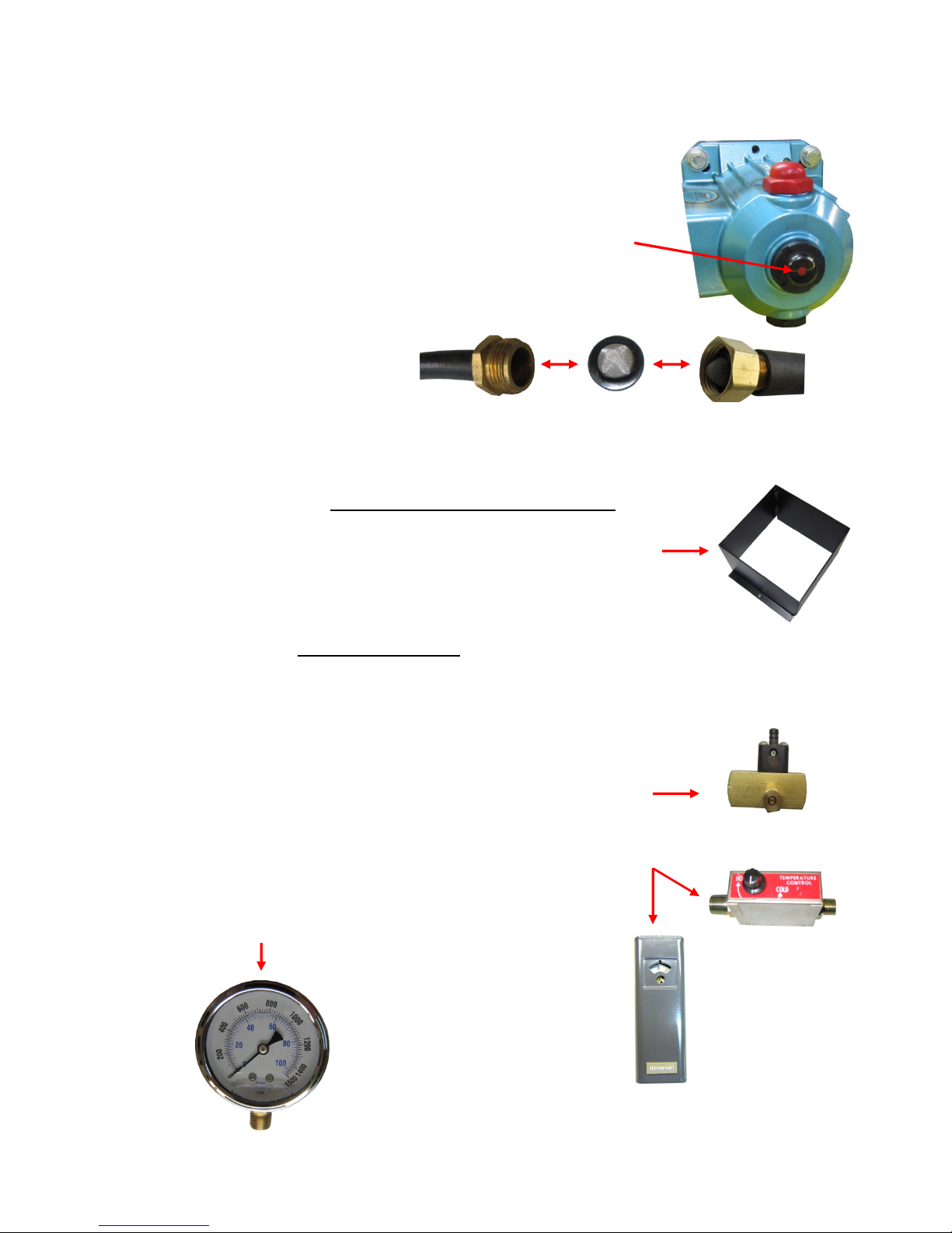
General Operating Instructions
1. Check Oil Level (See Honda gas engine Owner’s Manual for
additional information).
2. Check CAT pump oil level. Oil level must be up to the red
center dot (see CAT Service Manual).
3. Connect pressure water supply hose or immerse suction hose
in adequate clean water supply. Be sure screen is in place.
4. Connect electrical power
A. Burner 120VAC
B. Pump Motor 220VAC (specified phase)
5. Check engine fuel supply if applicable.
6. Hot washer - check burner fuel tank for adequate fuel supply
(#1 or #2 Heating Oil). Do not use kerosene or bio-diesel.
7. Installed on each washer is a square soap container box that
will accept a one gallon jug. Most products need to be diluted
prior to use. Powered soaps are unacceptable.
WARNING: Secure gun and lance prior to starting the pump.
CAUTION: Momentarily open the gun valve to relieve pressure prior
to starting the pump motor or engine.
8. Start the pump motor.
9. Hot washer – Ignite burner with control switch (see Beckett
AFG manual for additional burner information).
10. Soap (Dema) injector – Adjust metering screws for adequate
flow (see page 7 for additional info).
11. Temperature controller/thermostat – Adjust water temperature
to desired operating level.
12. Check pump operating pressure. Do not exceed
manufacturer’s recommended pressure. Begin cleaning.
6
TEMPERATURE CONTROL – 430027
Adjust temperature control to the desired temperature.
HOT
TEMPERATURE
CONTROL
COLD
Typical Wiring
To Flow Switch
To Control Switch
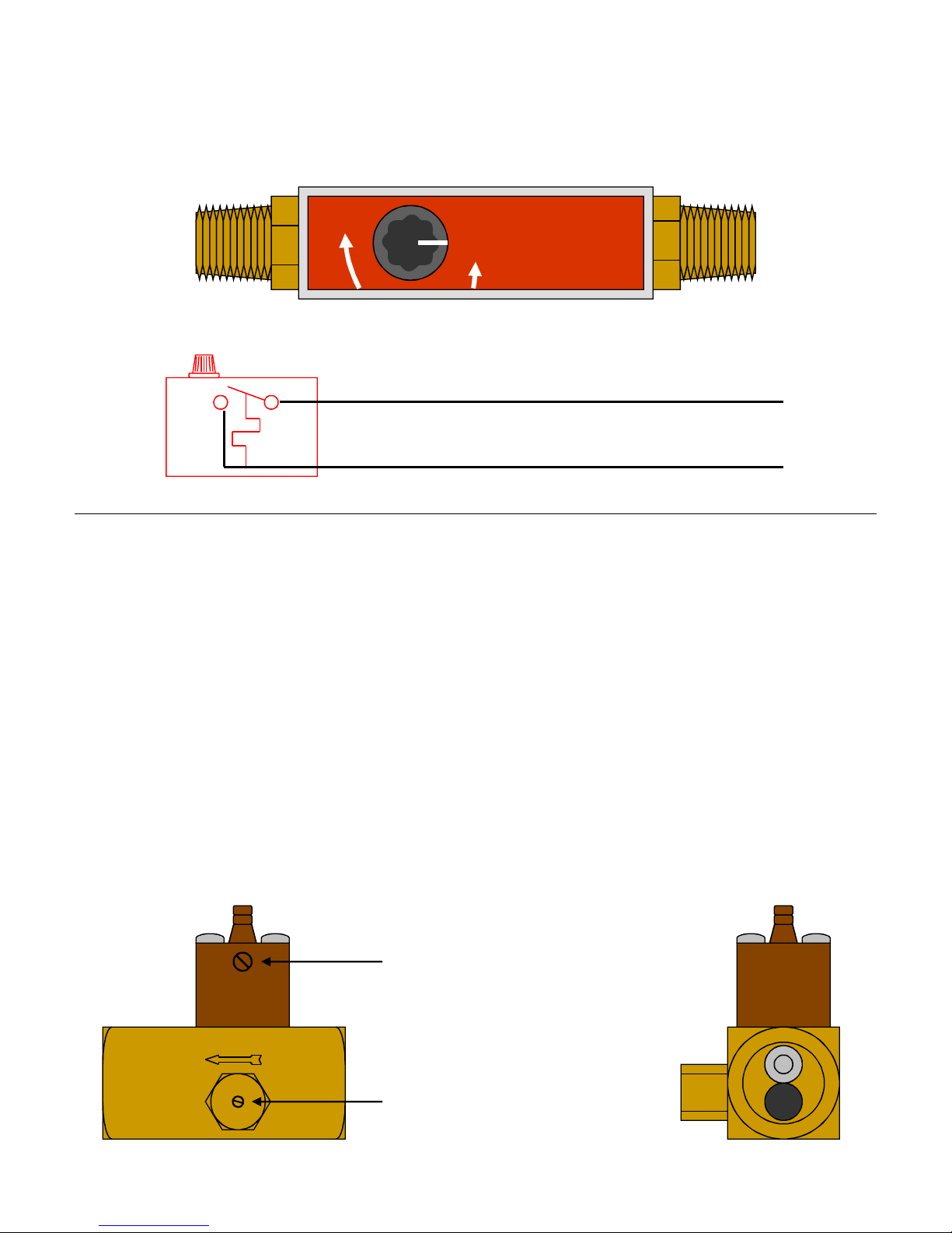
OPERATION – DEMA INJECTOR 203B / 204B
Warning: Use care when handling hazardous chemicals.
Warning: Setting the water bypass screw too far in could starve and damage the pump.
See figure below for location of water bypass screw and fine metering adjustment screw. Turn on water
supply valve. The injector may draw momentarily as the system is filling but normally will stop as the
system builds up to full pressure. To actuate injector, turn the bypass screw clockwise until product
begins to be drawn from the container. After the fluid reaches the injector, the feed rate may be
adjusted to the desired rate by turning the bypass screw. For low injection rates, it is advisable to set
the bypass screw for more injection than required; then turn the fine metering screw clockwise to
reduce injection to the desired rate. If the injector will not draw with the bypass screw full in, then the
water flow is below the range of the injector. If the injector draws with the screw full out but pressure
loss is excessive, then flow is above the range of the injector.
Fine Metering Adjustment Screw
Water By-pass Screw
7

Gems (Thomas Products) FS-925 Flow Switch
Hermetically sealed
SPDT switch
Permanent Magnet
Piston
No.18 AWG Leads
Spring
Operating Principle - A magnet-equipped piston, displaced by the pressure differential
from fluid flow, magnetically actuates a hermetically sealed, SPDT reed switch within the
unit. The switch is factory set and must not to be adjusted in the field. This switch, in turn,
operates a remote relay, providing system control. The piston metering land diameter
precisely sets the actuation point by regulating by-pass clearance. Spring return of the
piston is positive as flow decreases. Do not remove the non-metallic spacer from
between the metal base and flow switch, magnetic interference could result.
Repair Procedure - Magnet and plunger are molded as a unit. Cracks and deformation
may occur with time. Replacement parts are available.
Rough spots on the plunger and swollen plastic can be dressed down for smooth
operation with a fine metal file or emery cloth (180 grit or finer).
A thin coat of Vaseline will lubricate the plunger for smooth operation.
Special adjustments are required for proper installation of the SPDT reed switch. Do not
remove this unit from the brass body of the switch without factory instructions.
GEMS
FLOW
SWITCH
LOAD-PAK
SWITCH LOAD
VARISTOR
(M.O.V.)
LOAD
Typical Wiring
Maintenance – Accumulation of foreign
debris should periodically be removed from
these switches. Occasional “wipe-down”
cleaning when excessive contamination is
present is all that is normally required. To
clean: Remove unit from system and
disassemble as shown (left). Clean all
parts, reassemble and reinstall unit.
8

Johnson Controls Flow Control
Model F61KD-3C / F61KD-4C
Operation – The flow switch responds to pressure exerted on the fluid paddle by the
flowing fluid. During normal operation, the circuit between the red and yellow leads
(terminals) closes when sufficient fluid flows through the piping to trip the flow switch.
When a “no flow” condition exists, the switch opens, breaking the circuit and shutting down
the burner.
Typical Wiring
Siebring Hot Washers
To
power
source
!!!!
Risk of Improper Operation
The switch is set near the minimum flow
rate. Do not set lower than factory setting
as this may result in the switch failing to
Troubleshooting:
- Switch does not activate
Possible debris caught within switch mechanism. Clean mechanism, test switch operation
several times to ensure proper operation.
- Control switch action is reversed
Has flow switch been changed? Ensure connections match wiring diagram.
-Switch fails to return to “no flow” position
Stuck flow gate – clean to free up movement
Switch setting has been set lower than factory setting. Increase setting.
- Control does not switch on flow increase
Low water pressure. Check for cracked/broken paddle. Replace if necessary.
Internal damage form freezing conditions may require switch replacement.
- Switch failure is suspect. The following check is for troubleshooting only!
Jumper across red / yellow terminal and check for machine operation. If machine operates
normally, replace switch. Remove jumper.
CAUTION
return to a “no flow” position.
!!!!
Disconnect power before making any
electrical connections. Failure to follow
this precaution may result in equipment
WARNING
Risk of Electrical Shock
damage, electrical shock of death
Not used
To thermostat
or burner
Repairs and replacement – Field repairs, except for the replacement of the cover can not
be made. Contact Siebring Manufacturing for replacement flow switch.
9
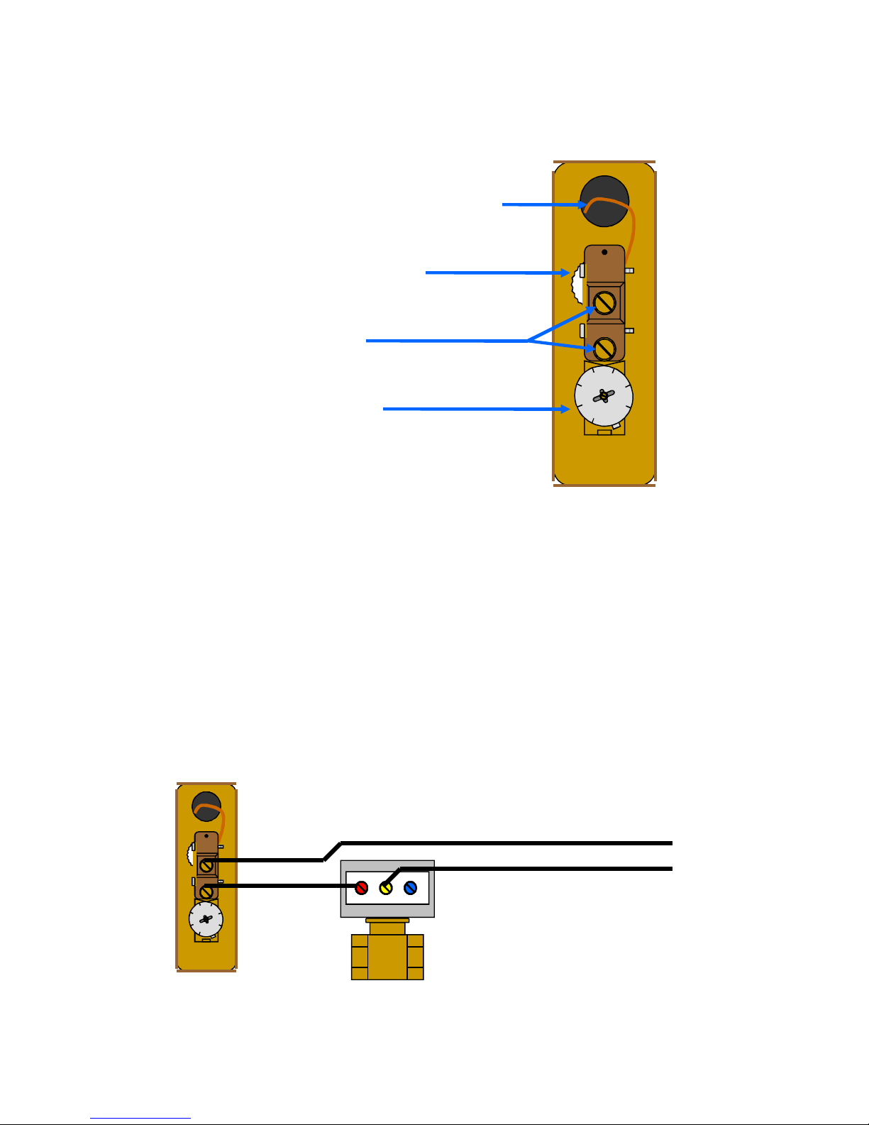
Honeywell Aquastat Controller L4006A
Copper Capillary Tube (to sensing bulb)
Differential Adjustment Wheel
5
Wire Terminal Screws
Set-point Indicating Dial
Operation - L4006A breaks the circuit on a temperature rise to the control setting.
High limit controller: Shuts off burner when water temperature exceeds high limit setting.
Burner restarts when temperature drops to high limit setting. Low limit controller:
Maintains minimum water temperature. Turns burner on at temperature setting, less
differential. Differential Adjustment wheel, typically used on boiler applications. Factory
set to 5°.
Checkout - Check to make certain that the Aquastat Controller has been installed and
adjusted properly. Put the system into operation and observe the action of the device
through several cycles to make certain that it provides proper control of the system as
described in the Operations section. Further adjustments can be made as required.
5
L4006A Flow Control
Typical Wiring
To Burner
To Switch
10
 Loading...