

Page 1
SIEB & MEYER
Drive Amplier SD2B /
SD2B plus
Hardware Description
W
P-TD-0000312.8
2019-09-09
Page 2

Copyright
Translation of the original instructions, Copyright © 2019 SIEB & MEYER AG
All rights reserved.
This manual or extracts thereof may only be copied with the explicit authorization of
SIEB & MEYER AG.
Trademarks
All product, font and company names mentioned in this manual may be trademarks or registered
trademarks of their respective companies.
SIEB & MEYER worldwide
For questions regarding our products and technical problems please contact us.
W
SIEB & MEYER AG
Auf dem Schmaarkamp 21
21339 Lueneburg
Germany
Phone: +49 4131 203 0
Fax: +49 4131 203 2000
support@sieb-meyer.de
http://www.sieb-meyer.de
SIEB & MEYER Asia Co. Ltd.
4 Fl, No. 532, Sec. 1
Min-Sheng N. Road
Kwei-Shan Hsiang
333 Tao-Yuan Hsien
Taiwan
Phone: +886 3 311 5560
Fax: +886 3 322 1224
smasia@ms42.hinet.net
http://www.sieb-meyer.com
SIEB & MEYER Shenzhen Trading Co. Ltd.
Room A208, 2/F,
Internet Innovation and Creation services base
Building (2),
No.126, Wanxia road, Shekou, Nanshan district,
Shenzhen City, 518067
China
Phone: +86 755 2681 1417 / +86 755 2681 2487
Fax: +86 755 2681 2967
sm_china_support1@163.com
http://www.sieb-meyer.cn
2 Drive Amplifier SD2B / SD2B plus - Hardware Description
Page 3

W
Chapter Overview
About this Manual
General Information 2
Safety Instructions 3
Unit Assembly Complying EMC 4
Drive Amplifier SD2B / SD2B plus 5
Device variant SD2B 6
Device variant SD2B plus 7
Connector Pin Assignment 8
1
Connection Examples 9
Status Display and Error Messages 10
General Information Regarding the Wiring 11
Electric Performance Dimensioning 12
Safety Circuit / Restart Lock (STO) 13
Appendix 14
Index
15
Drive Amplifier SD2B / SD2B plus - Hardware Description 3
Page 4

Chapter Overview
W
4 Drive Amplifier SD2B / SD2B plus - Hardware Description
Page 5

W
1 About this Manual ............................................................. 9
1.1 Illustration of Warnings ............................................................................... 9
1.2 Illustration of General Notices ...................................................................
1.3 Abbreviations ............................................................................................ 10
2 General Information ........................................................ 11
3 Safety Instructions ........................................................... 13
3.1 Standards and Regulations ....................................................................... 13
3.2 Working on the Device .............................................................................. 13
3.3 Appropriate Use ........................................................................................
3.4 Reasonably Foreseeable Misuse .............................................................. 15
3.5 Transport and Storage .............................................................................. 15
3.6 Installation ................................................................................................. 16
3.7 Electrical Connection ................................................................................ 17
3.8 Operation ..................................................................................................
3.9 Maintenance ............................................................................................. 19
3.10 Disposal .................................................................................................... 19
3.11 Legal Warranty .......................................................................................... 20
Content
10
14
18
4 Unit Assembly Complying EMC ...................................... 21
5 Drive Amplifier SD2B / SD2B plus .................................. 23
5.1 Type Plate ................................................................................................. 23
5.2 Device Designation ................................................................................... 24
5.3 Functional Overview of the Device Variants .............................................
25
6 Device variant SD2B ....................................................... 27
6.1 Operating Instructions ............................................................................... 27
6.2 Block Diagram ........................................................................................... 28
6.3 Dimensions/Mounting ............................................................................... 29
6.4 Technical Data .......................................................................................... 30
6.5 Connectors ................................................................................................ 31
7 Device variant SD2B plus ............................................... 33
7.1 Block Diagram ........................................................................................... 33
7.2 Dimensions/Mounting ...............................................................................
7.3 Technical Data .......................................................................................... 36
7.4 Connectors ................................................................................................ 37
35
8 Connector Pin Assignment .............................................. 39
8.1 Operation of the Terminal Connectors ...................................................... 39
8.1.1 Spring-cage Connection ........................................................................................ 39
8.1.2 Push-in Technology .............................................................................................. 39
8.2 ID switch ................................................................................................... 39
8.3 X2 – Motor Connection ............................................................................. 40
8.4 X4 – DC Power Supply ............................................................................. 40
8.5 X6 – Logic Supply ..................................................................................... 41
Drive Amplifier SD2B / SD2B plus - Hardware Description 5
Page 6

Content
8.6 X9 – Inputs/Outputs .................................................................................. 41
8.7 X10 – COM1 / Operating Terminal ............................................................ 42
8.8 X11 – USB ................................................................................................ 43
8.9 X12 – DC Power Supply ...........................................................................
8.10 X13 – Motor Connection ........................................................................... 44
8.11 X14 – Inputs/Outputs / Safety Circuit (STO) ............................................. 44
8.12 X15 – Encoder 0 .......................................................................................
8.13 X16 – Encoder 1 / Encoder Emulation ...................................................... 46
9 Connection Examples ..................................................... 47
9.1 X2/X13 – Motor Phases ............................................................................ 47
9.2 X4 – Decoupling of the Main Voltage ........................................................ 48
9.3 X4/X6 – DC Power Supply Unit ................................................................. 48
9.4 X9 – Inputs/Outputs ..................................................................................
9.4.1 Digital Inputs ......................................................................................................... 49
9.4.2 Digital Outputs ....................................................................................................... 49
9.4.3 Analog Input .......................................................................................................... 50
9.5 X9/X14 – Temperature Sensor of the Motor ............................................. 50
9.6 X10 – Bus Connection ..............................................................................
9.6.1 COM1 – RS232 ..................................................................................................... 51
9.6.2 CAN Bus ............................................................................................................... 52
9.7 X12/X14 – DC Power Supply Unit ............................................................. 53
9.8 X14 – In/Out / STO .................................................................................... 53
9.8.1 Digital Inputs ......................................................................................................... 53
9.8.2 Digital Outputs ....................................................................................................... 54
9.8.3 Analog Input .......................................................................................................... 55
9.8.4 safety circuit (STO) ............................................................................................... 55
9.8.4.1 Wiring with OSSD ................................................................................................. 55
9.8.4.2 Wiring without OSSD ............................................................................................ 56
9.9 X15, X16 – Incremental Encoder with TTL Signals ................................... 56
9.10 X16 – ENC1/EMU ..................................................................................... 57
9.10.1 Encoder Emulation ................................................................................................
9.10.2 Hall Sensor 5.3 V .................................................................................................. 58
9.10.3 PULSE IN 5.3 V .................................................................................................... 58
W
43
45
49
51
57
10 Status Display and Error Messages ................................
10.1 List of the Operating States ...................................................................... 59
10.2 List of Drive Error Messages .....................................................................
10.3 List of Warning Messages ......................................................................... 64
10.4 Message of the Quick Stop Functions ...................................................... 65
59
60
11 General Information Regarding the Wiring ...................... 67
11.1 Cable Requirements ................................................................................. 67
11.1.1 Motor Cable ........................................................................................................... 69
12 Electric Performance Dimensioning ................................ 71
12.1 Components .............................................................................................. 71
12.1.1 Output Stage ......................................................................................................... 71
12.1.2 Power Supply ........................................................................................................ 71
12.1.3 Motor ..................................................................................................................... 72
6 Drive Amplifier SD2B / SD2B plus - Hardware Description
Page 7

W
12.2 Power Consumption of a Drive ................................................................. 74
13 Safety Circuit / Restart Lock (STO) ................................. 75
13.1 Functional Description of the Restart Lock ............................................... 76
13.2 Wiring Example ......................................................................................... 77
13.3 Requirements and Standards ................................................................... 78
Content
14 Appendix .........................................................................
14.A Specification of Device Firmware ..............................................................
14.B Manufacturers ........................................................................................... 83
14.B.1 SIEB & MEYER Accessories ................................................................................ 83
14.B.1.1 Connectors of the Series SD2B / SD2B plus ........................................................ 83
14.B.1.2 Blocking Diode ...................................................................................................... 83
14.B.1.3 Operating Terminal ............................................................................................... 83
14.B.1.4 USB>RS232/485 Converter 050201 ..................................................................... 83
14.B.2 Phoenix Contact .................................................................................................... 84
81
81
15 Index ............................................................................... 85
Drive Amplifier SD2B / SD2B plus - Hardware Description 7
Page 8

Content
W
8 Drive Amplifier SD2B / SD2B plus - Hardware Description
Page 9

W
1 About this Manual
This chapter descirbes symbols, signal words and abbreviations used in this manual.
More documentation can be downloaded from the SIEB & MEYER website
under http://www.sieb-meyer.de/downloads.html.
1.1 Illustration of Warnings
Depending on their degree of risk, warnings are classified into different levels. In the
manual, the different levels and types of dangers are represented as follows:
About this Manual
1
[1] Risk level (signal word/warning color)
Classification of the risk
[2] Safety symbol
Risk of injury
[3] Risk symbol
Graphic representation of the source of risk
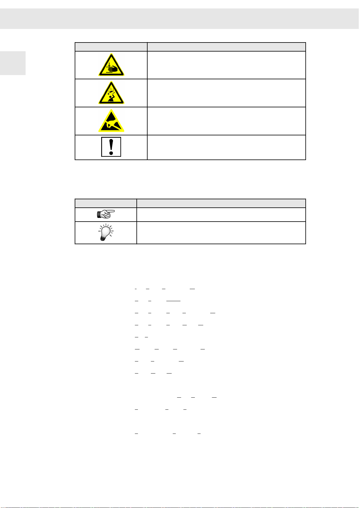
Risk levels
Risk Level
Risk symbols
Risk symbol
Description
Indicates an imminently hazardous situation which, if not avoided, will
result in death or serious injury.
Indicates a potentially hazardous situation which, if not avoided, could
result in death or serious injury.
Indicates a potentially hazardous situation which, if not avoided, may
result in minor or moderate injury or property damage.
Indicates a hazardous situation which, if not avoided, may result in prop‐
erty damage.
Description
General hazardous situation
Risk of injury due to electric shock
Risk of injury due to hot surfaces
Drive Amplifier SD2B / SD2B plus - Hardware Description 9
Page 10
About this Manual
W
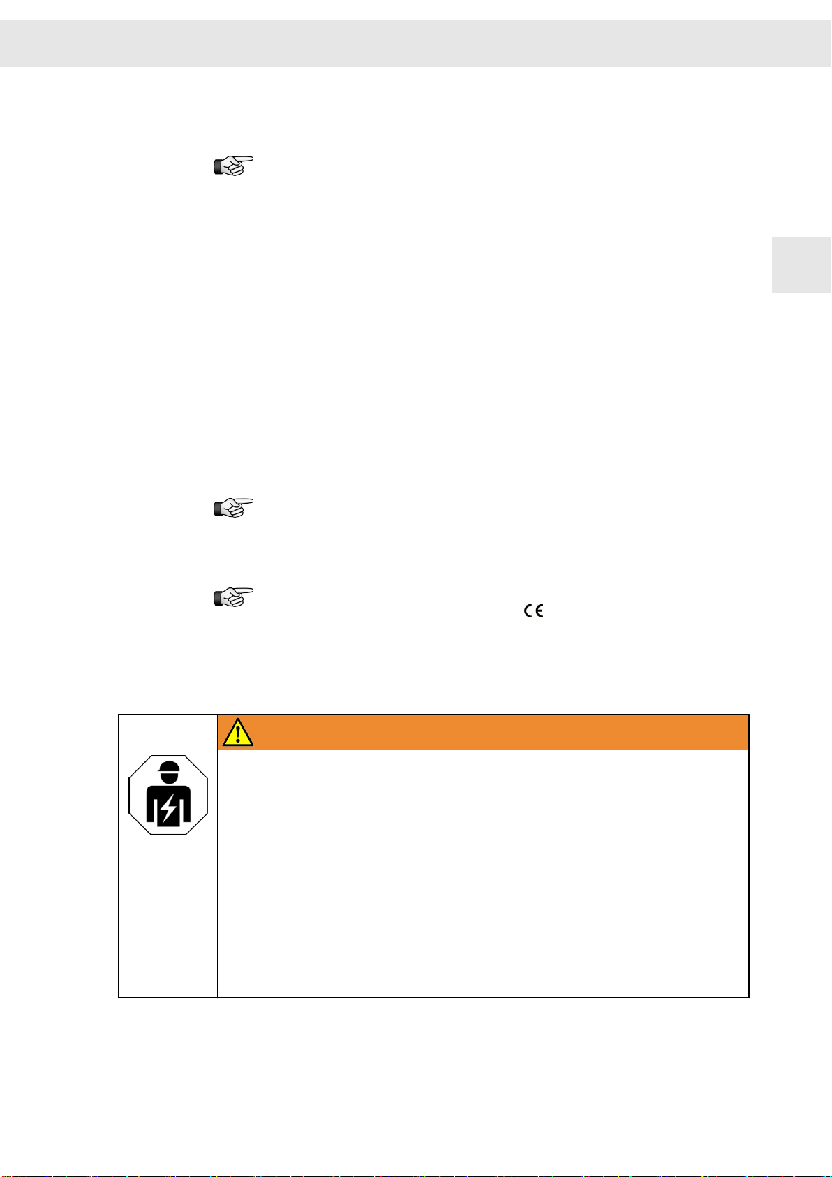
Risk symbol Description
1
Potentially risk of injury when working on machines with open covers/
doors
Risk of injury due to flying objects
Destruction risk of electrostatically sensitive components
Risk of property damage
1.2 Illustration of General Notices
Symbol Description
Hint with additional, further information
Tip with suggestions and useful information
1.3 Abbreviations
FPAM flux pulse amplitude modulation
HSBLOCK high-speed block commutation
HSPAM high-speed pulse amplitude modulation
HSPWM high-speed pulse width modulation
n.c. not connected
OSSD Output Signal Switching Device
PAM pulse amplitude modulation
PWM pulse width modulation
SERVO servo control
STO safety function: Safe Torque Off
SVC sensorless vector control
VF V/f Characteristic Curve
VCC voltage at the common collector
VECTOR vector control
10 Drive Amplifier SD2B / SD2B plus - Hardware Description
Page 11

W
2 General Information
This manual describes the drive amplifiers of the series SD2B / SD2B plus. These
devices allow operation of high-dynamic servo motors as well as synchronous and
asynchronous high-frequency spindles.
The devices are equipped with interfaces for different sensor systems and allow the
operation of motors with Hall and incremental sensors. Motor systems without any
sensors are also supported, whereas different customized control methods are avail‐
able. In addition, the devices can drive rotary and linear motors. Thus, the number of
device variants is reduced for the machine manufacturer.
This manual provides information on:
▶ Safety instructions and application advice
▶ Notes about the electromagnetic compatibility
▶ Description of the device (block diagram, type plate, module designation)
▶ Technical data, dimensions
▶ Connector pin assignment
▶ Wiring examples
▶ Status and error messages
▶ General information regarding the wiring (cables and line cross-sections)
General Information
2
This manual has the following demands on the trained staff of machine manufacturers:
Transport: only by skilled employees familiar with handling electrostatically
sensitive components.
Installation: only by experts with electromechanical experience
Initial operation: only by experts with experience in the fields of electrical engi‐
neering / drive technology
Information concerning the initial operation and parameterization of the
digital drive amplifier can be found in the manual of the software
master2
More documentation can be downloaded from the SIEB & MEYER website
under http://www.sieb-meyer.de/downloads.html.
.
drive‐
Drive Amplifier SD2B / SD2B plus - Hardware Description 11
Page 12

General Information
W
2
12 Drive Amplifier SD2B / SD2B plus - Hardware Description
Page 13
W
3 Safety Instructions
These safety instructions include important information regarding your safety
and must be observed during installation and operation of SIEB & MEYER
devices. Read them carefully and keep them for later use.
Also adhere to safety instructions in the product documentation and on the
device.
3.1 Standards and Regulations
SIEB & MEYER devices comply with the regulations of the following standards and
directives:
▶ Low-Voltage Directive 2014/35/EU:
EU declaration of conformity, DIN EN 61800-5-1
▶ EMC Directive 2014/30/EU:
EU manufacturer's certificate, DIN EN 61800-3
▶ Machinery Directive 2006/42/EC:
EU manufacturer's certificate, DIN EN 61800-5-2 (safety functions)
Safety Instructions
3
SIEB & MEYER products are no products according to the EU Machinery
Directive. The appropriate use of SIEB & MEYER devices in machines and
installations is prohibited until the manufacturer of the machine or installation
confirms the CE conformity of the complete machine or installation.
If the mechanics or the electronics of the device are modified, the conformity
with the EC/EEC directives and thus the label will expire.
3.2 Working on the Device
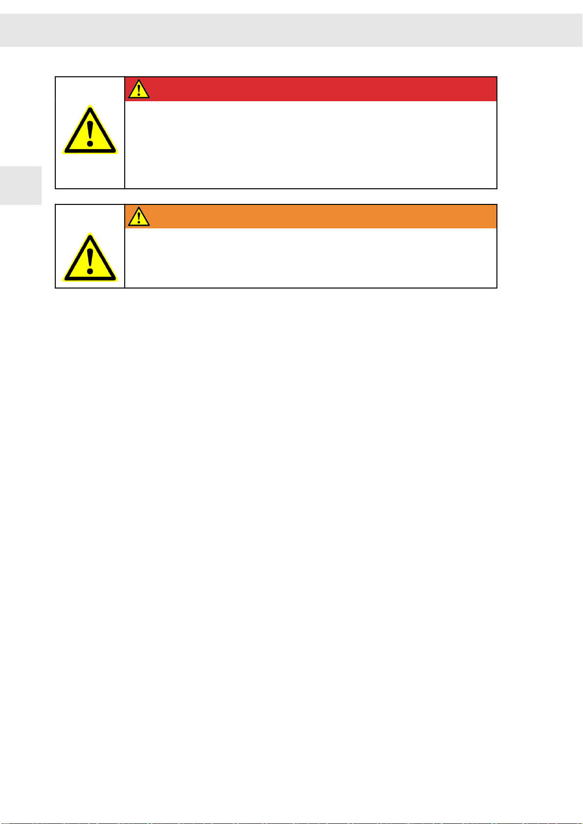
WARNING
Trained staff only
To avoid risks of serious injuries and material damage any works regarding instal‐
lation, initial operation and maintenance must be carried out by trained staff only.
Furthermore, electricians who connect feed-in systems must be approved by the
local DSO (distribution system operator).
Trained staff, according to this fundamental safety instruction, are persons familiar
with the installation, mounting, initial and permanent operation of the product and
they are qualified appropriately for the work. The standards DIN VDE 0100 and
DIN VDE 0110 as well as the national accident prevention regulations shall be
considered!
When installing feed-in systems adhere to all applicable regulations, special safety
instructions and technical connection conditions of the local DSO.
Drive Amplifier SD2B / SD2B plus - Hardware Description 13
Page 14
Safety Instructions
W
DANGER
Risk of serious damage to property and personal injury may occur:
▶ when covers are removed illegally,
▶ due to improper use,
▶ when either the installation or the operation is incorrect
Observe the corresponding notes and information in the product documentation of
3
your device.
WARNING
Risk of injuries and material damage due to illegal modifications
Only change the settings of the device after having contacted SIEB & MEYER.
All Information and advice attached to the device, such as safety instructions or danger
warnings and technical data (type plate) are:
▶ not to be removed
▶ not to be damaged
▶ to be kept readably (no covers, no paint over or the like)
3.3 Appropriate Use
Use the device according to its appropriate use only. Consider the corresponding infor‐
mation regarding the application fields of the device in the product documentation.
The device is intended for use within an enclosed cabinet by the OEM or end user to
comply with pollution degree 2 or equivalent environmental conditions. That means:
Ensure to avoid conductive impurities and humidity during the operation.
SIEB & MEYER products are not suitable for use in areas exposed to explosion
hazards (ATEX zones) without approriate housing.
Terms according to DIN EN 61800
Before initial operation, make sure that the machine will not expose danger (e.g.
runaway moves). The conformity with the safety standards DIN EN 60204-1 and DIN
EN 61800-5-1 must be ensured.
The manufacturer of the system or the machine has to meet the requirements of the
legal values regarding the Electromagnetic Compatibility (EMC). SIEB & MEYER units
can be operated in industrial areas, provided that the attached EMC information has
been taken into consideration.
SIEB & MEYER tests all products in its own EMC laboratory to ensure that the prod‐
ucts meet the respective standards, when they are installed properly.
Installation of the device differing from the product documentation and the manual
"EMC Guidelines" means that the machine manufacturer has to carry out new meas‐
urements to comply with the regulations.
SIEB & MEYER devices meet the requirements of the Low-Voltage Directive
2014/35/EU. The harmonized standards of DIN EN 50178 and DIN EN 60204-1 in
14 Drive Amplifier SD2B / SD2B plus - Hardware Description
Page 15

W
Safety Instructions
combination with the standards DIN EN 60947 and DIN EN 61800-5-1 are applied
consequently.
Technical data and the connection specification can be found in the respective product
documents.
Line filters
If adequate interference suppression measures are applied and the appropriate use in
industrial applications of the device is ensured SIEB & MEYER devices comply with
the EMC Directive EMC Directive 2014/30/EU in terms of the EMC Product Standard
(PDS) DIN EN 61800-3.
The use of line filters helps reaching the following:
▶ Resistance to interference. The electronic system is protected against high-
frequency disturbances, possibly infiltrated via the mains cable.
▶ Protection against radiation. High-frequency disturbances are reduced to legally
authorized measure. This prevents effects of the transients to adjacent compo‐
nents or devices.
▶ Products, not equipped with an integrated AC supply line filter must be operated
with an upstream line filter.
▶ Using SIEB & MEYER devices in residential or business areas as well in small
businesses requires additional interference suppression.
For detailed information refer to the manual "EMC Guidelines", chapter "EMC
Product Standard DIN EN 61800-3 for PDS".
3
Refer to the product documentation of your device to find out whether or not
your device is equipped with a line filter. For detailed information on line
filters refer to the manual "EMC Guidelines".
3.4 Reasonably Foreseeable Misuse
The Machinery Directive defines a "reasonably foreseeable misuse" as "use of machi‐
nery in a way not intended in the instructions but which may result from predictable
human behavior".
SIEB & MEYER products are no products according to the EU Machinery Directive.
During design and construction of the machine as well as in the operation manual the
machine manufacturer is obliged to give consideration to the intended (appropriate)
use of the machine and risks arising from reasonably foreseeable misuse of the
machine.
To avoid injuries and material damage any use, installation and setup of
SIEB & MEYER products by non-experts which exceed the technical data specified in
the product documentation (high voltages, temperatures etc.) is considered to be not
intended use and forbidden. Adhere to the safety instructions on the device and in the
product documentation.
3.5 Transport and Storage
Avoid improper mechanical load of the device. The following points must especially be
taken into consideration:
▶ Protect the device against mechanical damage (max. acceleration = 40 m/s²).
▶ Protect the device against dirt and humidity.
Drive Amplifier SD2B / SD2B plus - Hardware Description 15
Page 16
Safety Instructions
W
Make sure that dust plugs are plugged on optical fiber connectors equipped with
them during transport of the device. Otherwise, recommissioning is potentially not
possible.
▶ Never touch electronic components.
The following climatic conditions apply to the storage. If required, appropriate meas‐
ures must be taken to ensure these climatic conditions (installation of heating/air condi‐
tioning systems etc.):
▶ The storage area must be clean (dust-free, if possible), dry and well-ventilated.
▶ No storage in the open.
3
▶ The storage temperature must be in the range of −25 °C to +55 °C (−13 °F to
+131 °F). Shortly it may be +70 °C (+158 °F).
▶ The relative humidity on the storage premises must be in the range of 5 % to 75 %
(no bedewing).
▶ Sudden changes of the temperature or the humidity should be prevented.
▶ Avoid stacking of the devices during transport and storage.
The maximum storage period is 2 years. Electrolytic capacitors produce high leakage
currents when a voltage is applied after a long storage period without applied voltage
and must be reformed. For this, the operating voltage is applied via a 1 kΩ series
resistor for one hour. Please contact the SIEB & MEYER service department for
details.
3.6 Installation
NOTICE
Damage of electrostatically sensitive components due to improper handling
Never touch electronic components.
Consider specific mounting instructions for your device.
Mechanical installation conditions for the system according to DIN EN 61800-2:
Vibrations must remain within the limit values of the IEC 60721-3-3, class 3M1,
standard for fixed equipment.
Frequency [Hz]
2 ≤ f < 9 0,3 Not applicable
9 ≤ f < 200 Not applicable 1
Tab. 1: Vibration limits of the system
Vibrations which exceed these limits, or the use on mobile equipment, are considered
as abnormal mechanical conditions.
Amplitude [mm] Acceleration [m/s²]
Operating conditions:
The following requirements are to be considered for the installation and the operation
of the device. Noncompliance with theses requirements is regarded as abnormal oper‐
ating condition:
▶ The device is conceived according to DIN EN 61800-1 / DIN EN 50178 for the dirt
level 2. That means: Ensure to avoid conductive impurities during the operation.
▶ Devices with air cooling only can be loaded to their maximum up to a height of
1000 m above MSL (3281 ft above MSL). For an operation in areas higher than
16 Drive Amplifier SD2B / SD2B plus - Hardware Description
Page 17
W
Safety Instructions
1000 m (3281 ft) above MSL the capacity must be reduced by 1.5 % per 100 m
(328 ft).
The maximum site altitude is 2000 m (6562 ft) above MSL.
▶ The device must be protected against harmful gas, oil vapor and salty air at the
place of installation.
▶ The ambient air must not contain aggressive, grinding, electrically conductive or
flammable substances as well as any amount of dust.
▶ The maximum relative humidity during operation is 85% (no condensation).
▶ The admissible ambient temperature during operation is +5 °C to +40 °C (+41 °F
to +104 °F). Extreme and sudden changes of the temperature should be
prevented.
─ Ensure power derating for devices used under ambient temperatures over
+40 °C (+104 °F) (see technical data). The following applies:-1.5 % per
1 °C.Note: F=C×9/5+32; C=(F-32)×5/9
─ Devices with polyester film at the front panel: The polyester films must not be
exposed to direct sunlight for extended periods of time. In conditions of high
humidity (>80 %) the ambient temperature must not exceed +40 °C (+104 °F).
The polyester films must not come in contact with benzyl alcohol or methylene
chloride.
▶ Make sure that the aeration elements are free and open, so that the air circulation
is not restricted.
3
3.7 Electrical Connection
DANGER
Risk of serious injuries due to touch voltages
After electric devices have been switched off touch voltages may occur depending
on the device up to 4 minutes. Longer construction-related discharge times are
possible. Refer to the product documentation of your device.
All work at and within the units must only be carried out, when the units are turned
off, the mains supply is cut and the DC bus is completely discharged.
Never touch energized parts after a device has been switched. off.
Consider the applicable VDE regulations and accident prevention regulations (e.g.
VBG 1 and VBG 4).
DANGER
Risk of serious injuries due to improper connection to earth
Incorrect or insufficient connection of the system to earth may cause dangerous
currents.
Connection to earth must be realized according to the instructions in the product
documentation of your device.
The electrical installation must be carried out according to the relevant electrical codes
(e.g. appropriate wire gauges, fuse protection and connections of ground conductors
must be considered).
Drive Amplifier SD2B / SD2B plus - Hardware Description 17
Page 18
Safety Instructions
W
SIEB & MEYER device are conceived for connection to TN mains. For
detailed information regading the connection to TN mains or other mains
refer to the manual "EMC Guidelines", chapter "Connection to Different
Supply System Types".
Recommendations for the installation complying EMC (e.g. shields, connection to earth
and line installations) can be found in the technical manuals of your device (only for
machine manufacturers). The manufacturer of the system or machine has to meet the
requirements of the legislation regarding the EMC.
3
➮ Consider that the mains supply must be protected via an overload release with
restricted guidance for each mains phase. The mains line should only be
connected, when the work is completed.
➮ Before turning on the unit the first time, make sure that the connected machine will
not have runaway axes.
➮ Never connect capacitive loads to the output phases of the servo amplifiers and
frequency converters.
➮ Prevent cable loops. Therefore, the units must only be connected to earth at the
provided PE connection for the mains supply line and the racks only at the
provided earth screw.
DANGER
Connection of the power supply unit
This product may cause touch current in the protective earthing conductor. The
current in the protective earthing conductor can exceed 3.5 mA AC or 10 mA DC.
Pay attention to the local safety regulations for electric equipment with high
leakage currents, in particular the minimum cross-section of the protective earthing
conductor.
Operation with residual current device (RCD)
For detailed information regarding the operation with residual current device
(RCD) refer to the manual "EMC Guidelines", chapter "Safety-relevant
Aspects, Residual Current Device (RCD)".
3.8 Operation
WARNING
Risk of serious injuries due to moving machine parts
During the operation of an installation with open doors or removed covers, persons
may seriously be injured by moving machine parts.
Keep the doors closed during the operation and do not remove covers.
18 Drive Amplifier SD2B / SD2B plus - Hardware Description
Page 19
W
Safety Instructions
WARNING
Risk of injuries and material damage due to flying parts
Persons may be injured or material be damaged, if screws of the front panels and
housing parts are not fastened.
Before the initial operation of the installation ensure that all screws are tightened.
3
WARNING
Risk of burn due to hot surfaces
During operation the units can have hot surfaces according to their protection
system. In particular this applies to ventilation inlets and outlets.
Never touch device parts during operation apart from operating units.
When using ferrite rings temperatures may exceed 80°C in some cases.
Only use cables suitable for temperatures over 90 °C. This corresponds to the
flammability rating UL 94V-0, RTI 105°C.
Consider the relevant notes in the manual.
Systems, into which servo amplifiers and frequency converters are mounted, possibly
must be equipped with additional protective devices according to the valid safety
instructions (e.g. law about technical material, rules for prevention of accidents, etc.).
3.9 Maintenance
The unit must be checked regularly for cleanness and functionality depending on the
ambient pollution. This applies in particular for installed fans.
3.10 Disposal
Make sure to consider country-specific waste and disposal laws and statutes
for the disposal of packing material, used batteries and irreparable devices.
SIEB & MEYER products meet the requirements of the following directive:
▶ 2011/65/EU (EU-directive RoHS 2 on the restriction of the use of hazardous
substances in electrical and electronic equipment)
SIEB & MEYER products do not exceed the limits of the directive 2011/65/EU for
hazardous substances.
SIEB & MEYER products labeled with the adjacent symbol also meet
the regulations of the following directive:
▶ SJ/T 11364-2014 (China RoHS 2 on the restriction of the use of
hazardous substances in electrical and electronic equipment)
SIEB & MEYER products labeled with the symbol above do not exceed
the limits of the directive SJ/T 11364-2014 for hazardous substances.
Drive Amplifier SD2B / SD2B plus - Hardware Description 19
Page 20

Safety Instructions
W
3.11 Legal Warranty
SIEB & MEYER products are liable to a legal warranty of at least one year. Any claims
for the products beyond this warranty shall be declared in an additional contractual
agreement between SIEB & MEYER and the customer.
Claims for damages are excluded:
▶ due to improper use of the device
▶ when the device has been installed nonstandard or improperly, especially by elec‐
3
tricians without license
▶ when the device has been employed although the protection equipment was
defective
▶ when the maximum permissible input voltage has been exceeded
▶ due to improper operation
▶ when the device or its equipment have been modified
▶ when the device was affected by foreign material or force majeure
NOTICE
Due diligence of the machine manufacturer
A first programming carried out by SIEB & MEYER does not release the machine
manufacturer from his duty to check the programmed values for correctness.
20 Drive Amplifier SD2B / SD2B plus - Hardware Description
Page 21

W
Unit Assembly Complying EMC
4 Unit Assembly Complying EMC
The EU guidelines for electromagnetic compatibility (EMC) must be consid‐
ered for the initial operation of all SIEB & MEYER devices.
The manual "EMC Guidelines" is available in German and English and includes:
▶ EMC rules
▶ information regarding the professional grounding and wiring
▶ safety-relevant aspects
▶ extracts from the EMC product standard
▶ possibilities for the connection to different supply system types
Availability:
▶ PDF file under www.sieb-meyer.de/downloads.html
4
Drive Amplifier SD2B / SD2B plus - Hardware Description 21
Page 22

Unit Assembly Complying EMC
W
4
22 Drive Amplifier SD2B / SD2B plus - Hardware Description
Page 23
W
Drive Amplifier SD2B / SD2B plus
5 Drive Amplifier SD2B / SD2B plus
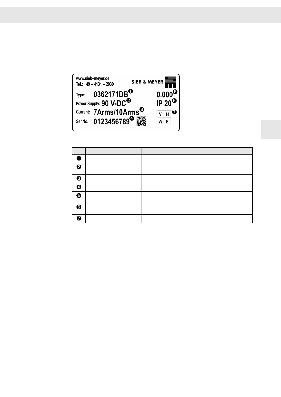
5.1 Type Plate
Fig. 1: Example of type plate (SD2B plus)
No. Meaning Explanation
Device designation Composed of module type and performance range as letter code
5
Supply voltage Indicates the maximum voltage range (if this row is left blank, an
Rated current/peak current Applies to the output stage; indicated as RMS value
Serial number Indicates the individual number of the device
Device version Indicates the version of the hardware; if no version is existent,
IP Code Indicates the level of protection of the device against touching or
QA label
external power supply unit is necessary)
0.000 is indicated here
intrusion of solid objects (1st digit) and water ingress (2nd digit)
Drive Amplifier SD2B / SD2B plus - Hardware Description 23
Page 24
Drive Amplifier SD2B / SD2B plus
W
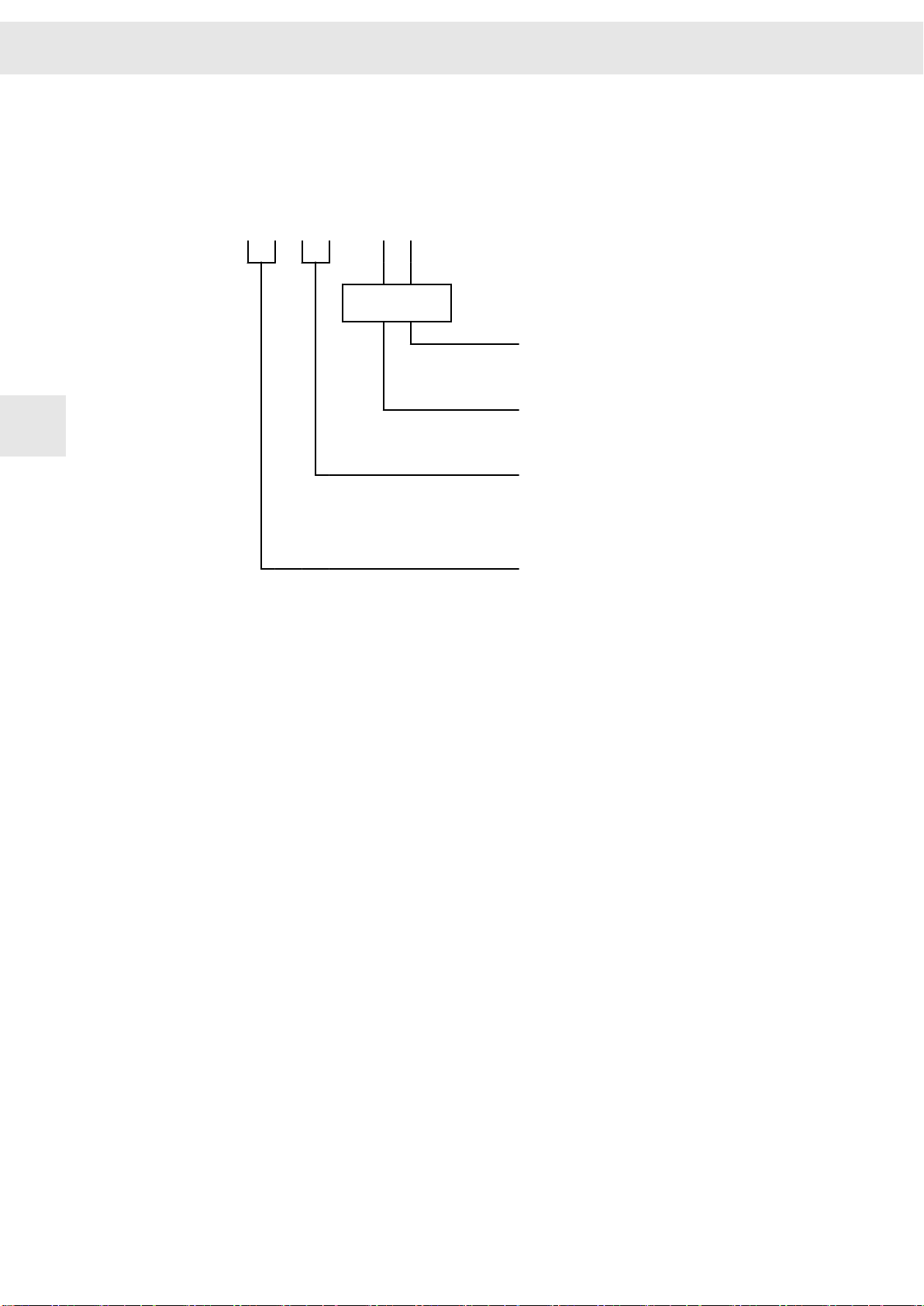
5.2 Device Designation
e.g.0362170DB 3.000
Device type Device version
0 3 6 X X X X - x y
Current range
5
Specific type code
Module type
Performance
range
Voltage class
▶ B = up to 90 V
▶ see technical data
▶ 7X = drive amplifiers SD2B / SD2B plus
70 = SD2B (without housing)
71 = SD2B plus (with housing)
▶ 21 = series SD2x
DC
Device version X.XXX
Serial counter. If no version is existent, 0.000 is indicated here. If a device is
exchanged by a device of another version, please contact SIEB & MEYER to check
whether the devices are compatible or not.
In addition the device version indicates the update capability of the internal device soft‐
ware, e.g. BIOS, FPGA or Firmware.
24 Drive Amplifier SD2B / SD2B plus - Hardware Description
Page 25
W
Drive Amplifier SD2B / SD2B plus
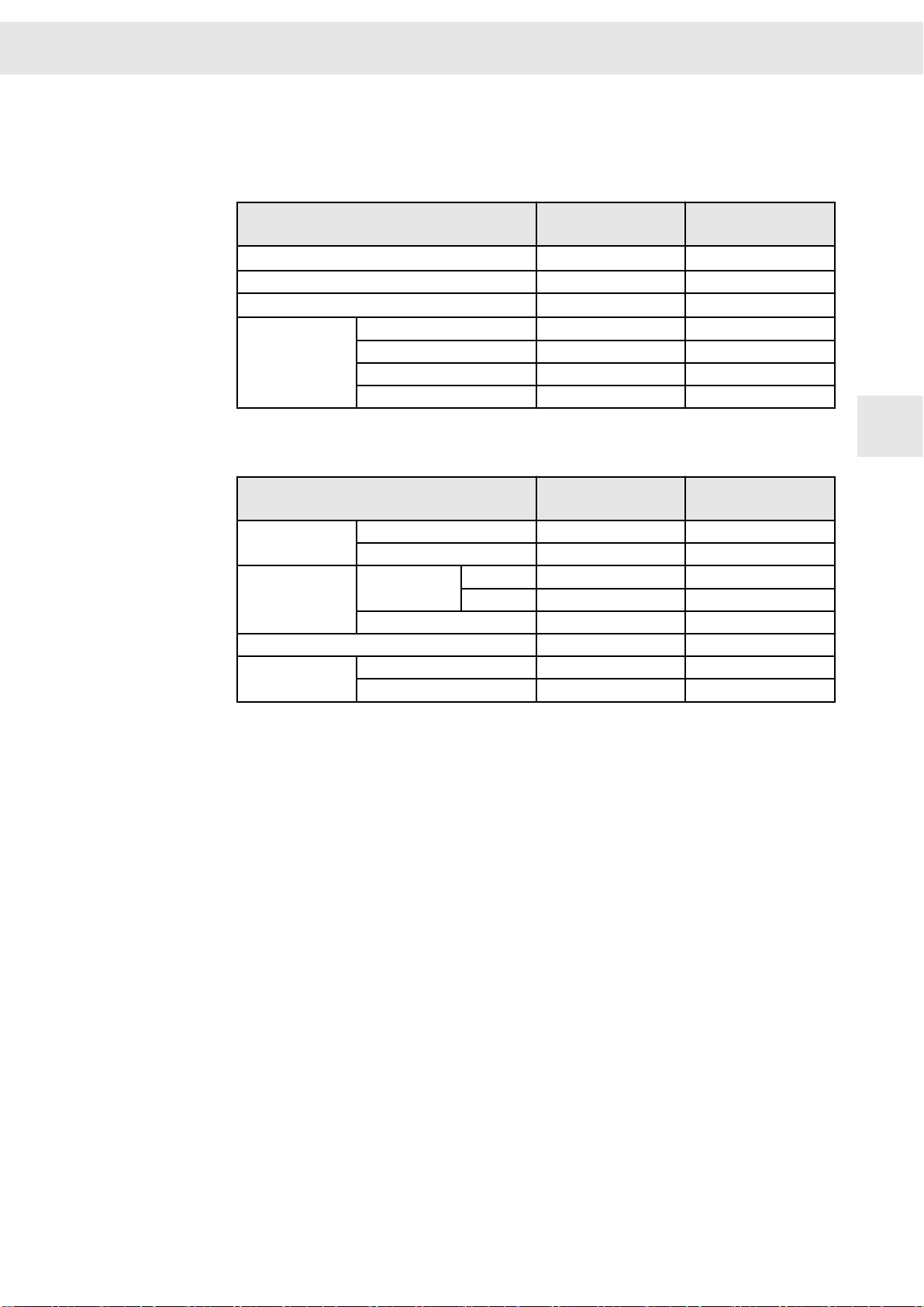
5.3 Functional Overview of the Device Variants
The following tables show the properties and the supported drive function of the
devices SD2B and SD2B plus.
General properties
Max. output power S1
Mains supply: External DC power supply ✔ ✔
DC link: fix
Interfaces
(1)
The maximum output power S1 applies at a voltage supply of 80 VDC.
(2)
The fix DC voltage supply depends on the used external power supply unit.
Drive function (up to … kHz output frequency) SD2B
SERVO / VECTOR
HSBLOCK / FPAM
HSPWM – –
HSPAM / VF
(2)
(1)
X9 (I/O)
X11 (USB) – ✔
X14 (I/O, safety) – ✔
X15/X16 (encoder 0/1) – ✔
SERVO – ✔ (up to 2 kHz)
SVC ✔ (up to 2 kHz) ✔ (up to 2 kHz)
HSBLOCK (with
sensor)
FPAM (sensorless) – –
VF-PWM ✔ (up to 2 kHz) ✔ (up to 2 kHz)
VF-PAM – –
PWM (Hall) – ✔ (up to 6 kHz)
PAM (Hall) – –
SD2B
(0362170DB)
660 VA 940 VA
✔ ✔
✔ –
(0362170DB)
SD2B plus
(0362171DB)
SD2B plus
(0362171DB)
5
Drive Amplifier SD2B / SD2B plus - Hardware Description 25
Page 26

Drive Amplifier SD2B / SD2B plus
W
5
26 Drive Amplifier SD2B / SD2B plus - Hardware Description
Page 27

W
6 Device variant SD2B
Device variant SD2B
6
Fig. 2: Device view of SD2B (0362170DB)
6.1 Operating Instructions
With its single-board design the device is to be integrated into the customer's electrical
construction on a sufficient cooling surface.
DANGER
Operating voltages above 48 V
In order to avoid personal injuries provide for protection against contact when oper‐
ating voltages above 48 V are reached (e.g. install the device in a switch cabinet).
WARNING
Hot surfaces
During operation the heat sink and components can reach temperatures above
80 °C.
Do not touch the device during operation.
Make sure that there are no combustible materials near by the device and that the
heat sink is not covered during mounting and operation.
Take measures to protect the device against contamination, in particular due to
conductive or aggressive materials. Contamination can cause malfunctions and shortcircuits.
Drive Amplifier SD2B / SD2B plus - Hardware Description 27
Page 28

Device variant SD2B
W
6.2 Block Diagram
The following block diagram shows the functional groups and connection options of the
device.
6
Fig. 3: Block diagram SD2B
28 Drive Amplifier SD2B / SD2B plus - Hardware Description
Page 29

W
6.3 Dimensions/Mounting
Device variant SD2B
6
Fig. 4: Dimensions SD2B in mm (inch)
▶ vertical mounting at spacers and heat sink: 4 M3 bolts
▶ wall mounting at heat sink: 2 M4 bolts
Drive Amplifier SD2B / SD2B plus - Hardware Description 29
Page 30

Device variant SD2B
6.4 Technical Data
Device variant 0362170DB
W
Parameterized supply voltage
(1)
Continuous phase current of output stage (±3 %)
Peak phase current of output stage (±3 %)
24 V
DC
7 A
(when mounted to cooling surface of the installation)
rms
10 A
(when mounted to cooling surface of the installation)
rms
48 V
DC
80 V
DC
(2)
(2)
Max. time for peak current 10 s
Max. output frequency 2000 Hz
Output frequency stability ≤ 0.2 %
Supply voltage
(3)
Output voltage
S
at I
(7 A
Output power
S
6
Logic supply
(4)
rated
S
at I
rated
) 190 VA 390 VA 660 VA
rms
(10 A
) 270 VA 550 VA 940 VA
rms
24 VDC (-10 %) to
24 VDC (+15 %)
16 V
AC
24 VDC (-10 %) to
48 VDC (+15 %)
33 V
AC
18 – 28 VDC (0.5 A)
24 VDC (-10 %) to
80 VDC (+15 %)
55 V
AC
Internal ballast resistor 22 Ω / 50 W
Maximum braking power 50 W 200 W for 5 s 450 W for 2 s
Ballast threshold 35 V
Overvoltage threshold 40 V
DC
DC
65 V
70 V
DC
DC
100 V
110 V
DC
DC
Undervoltage threshold 15 V
DC
Ambient temperature range 5 °C to 50 °C at a maximum relative humidity of 85 % (without moisture
condensation)
100 % rated current up to max. 40 °C. At higher temperatures the power
must be reduced by 1.5 % per 1 °C.
IP Code
(1)
Adjustable via software
drivemaster2
: from device version 4.100 and software version 1.14.100 onwards
IP00
For SD2B / SD2B plus with a device version < 4.100 the column 80 VDC applies. Device version 4.0xx can
be reconfigured to reach version 4.100, see “TIE_SD2B_AdjustableSupplyVoltage.pdf”.
(2)
Minimum size of cooling surface: 6 dm² (natural convection)
(3)
Admissible voltage ripple: max. 10 %
The supply voltage is protected by a fuse on the device: 10 A medium slow (5 × 20 mm)
(4)
The logic voltage is necessary to maintain the error messages. It is protected by an electronic fuse on the
device.
30 Drive Amplifier SD2B / SD2B plus - Hardware Description
Page 31

W
Device variant SD2B
NOTICE
Voltage peaks during braking operation
During braking of high inertial masses and/or when using short braking times the
DC main voltage can increase significantly depending on the parameterized supply
voltage.
▶ supply voltage 24 VDC → max. overvoltage 40 V
▶ supply voltage 48 VDC → max. overvoltage 70 V
▶ supply voltage 80 VDC → max. overvoltage 110 V
The connected power supply unit must be designed for this voltage. If not, you
need to decouple the main voltage by means of a blocking diode to avoid damage
to the power supply unit (see connection example
6.5 Connectors
DC
DC
DC
page 48).
6
Fig. 5: Connectors of SD2B (top view)
You can order the appropriate connector kit for SD2B at SIEB & MEYER
(article No. 32299576).
Drive Amplifier SD2B / SD2B plus - Hardware Description 31
Page 32

Device variant SD2B
W
6
32 Drive Amplifier SD2B / SD2B plus - Hardware Description
Page 33

W
Device variant SD2B plus
7 Device variant SD2B plus
Fig. 6: Device view of SD2B plus (0362171DB)
7.1 Block Diagram
The following block diagram shows the functional groups and connection options of the
device.
7
Drive Amplifier SD2B / SD2B plus - Hardware Description 33
Page 34

Device variant SD2B plus
W
7
Fig. 7: Block diagram SD2B plus
34 Drive Amplifier SD2B / SD2B plus - Hardware Description
Page 35

W
7.2 Dimensions/Mounting
Device variant SD2B plus
Fig. 8: Dimensions SD2B plus in mm [inch]
Mounting Instructions
▶ The device is mounted horizontally or vertically to a mounting wall. The mounting
surface is used for cooling.
▶ The mounting surface must be able to dissipate a heat output of 25 W at a
housing temperature of 60 °C for each device.
▶ With vertical mounting several device can be mounted next to each other without
any space in-between.
7
Fig. 9: Mounting options
Drive Amplifier SD2B / SD2B plus - Hardware Description 35
Page 36

Device variant SD2B plus
7.3 Technical Data
Device variant 0362171DB
W
Parameterized supply voltage
(1)
Continuous phase current of output stage (±3 %)
Peak phase current of output stage (±3 %)
24 V
DC
10 A
(when mounted to cooling surface of the installation)
rms
12 A
(when mounted to cooling surface of the installation)
rms
48 V
DC
80 V
DC
(2)
(2)
Max. time for peak current 10 s
Max. output frequency 2000 Hz
Output frequency stability ≤ 0.2 %
Supply voltage
Output voltage
Output power
Logic supply
(3)
S
at I
rated
(10 A
) 270 VA 560 VA 940 VA
rms
S
S
at I
(12 A
rated
(4)
) 330 VA 680 VA 1140 VA
rms
24 VDC (-10 %) to
24 VDC (+15 %)
16 V
AC
24 VDC (-10 %) to
48 VDC (+15 %)
33 V
AC
18 – 28 VDC (0.5 A)
24 VDC (-10 %) to
80 VDC (+15 %)
55 V
AC
Internal ballast resistor 22 Ω / 50 W
7
Maximum braking power 50 W 200 W for 5 s 450 W for 2 s
Ballast threshold 35 V
Overvoltage threshold 40 V
DC
DC
65 V
70 V
DC
DC
100 V
110 V
DC
DC
Undervoltage threshold 15 V
DC
Max. power loss 25 W
Ambient temperature range 5 °C to 50 °C at a maximum relative humidity of 85 % (without moisture
condensation)
100 % rated current up to max. 40 °C. At higher temperatures the power
must be reduced by 1.5 % per 1 °C.
IP Code
(1)
Adjustable via software
(2)
Minimum size of cooling surface: 6 dm² (natural convection)
(3)
Admissible voltage ripple: max. 10 %
(4)
The logic voltage is necessary to maintain the error messages. It is protected by an electronic fuse on the
drivemaster2
: from software version 1.14.100 onwards
IP20
device.
36 Drive Amplifier SD2B / SD2B plus - Hardware Description
Page 37

W
7.4 Connectors
Device variant SD2B plus
Fig. 10: Connectors of SD2B plus
You can order the appropriate connector kit for SD2B plus at SIEB &
MEYER (article No. 32299587).
7
Drive Amplifier SD2B / SD2B plus - Hardware Description 37
Page 38

Device variant SD2B plus
W
7
38 Drive Amplifier SD2B / SD2B plus - Hardware Description
Page 39

W
Connector Pin Assignment
8 Connector Pin Assignment
8.1 Operation of the Terminal Connectors
8.1.1 Spring-cage Connection
The individual conductors are fixed in
the terminal by means of spring-cage
connection. In order to plug and unplug
a conductor proceed as follows:
▶ Push a screwdriver into the desig‐
nated groove above the chamber
to operate the spring-cage connec‐
tion as shown in the figure.
▶ Put the conductor into the
chamber / remove the conductor
from the chamber.
▶ Release the screwdriver.
Solid wires or conductors with ferrules can be put directly into the chamber
without the help of a screwdriver.
8.1.2 Push-in Technology
Terminals using the push-in connection
technology (PIT) work on the pressure
spring principle:
The contact spring presses the cable
against the conducting copper bar. The
special spring profile allows direct and
tool-free wiring of solid and stranded
cables previously assembled with
ferrule or compressed conductor ends.
▶ When the cable is inserted into the
clamping unit the spring opens
automatically.
▶ To open the clamp and loosen the
cable use a screw driver.
8
8.2 ID switch
➮ Set the address for the module by means of the address selection switch.
16 adresses are available: 0, 1, 2, 3, 4, 5, 6, 7, 8, 9, A, B, C, D, E, F.
The addresses of several devices in a system must be different from each
other to ensure that they can be identified by the software.
Drive Amplifier SD2B / SD2B plus - Hardware Description 39
Page 40

Connector Pin Assignment
8.3 X2 – Motor Connection
4-pole Combicon connector, suitable for mating connector MSTB 2,5/ 4-ST-5,08
(Phoenix)
Mating connector X2
Specification of terminal connections
▶ Conductor cross-section solid/stranded: 0.75 – 2.5 mm²
▶ Tightening torque: 0.5 – 0.6 Nm
Related topics
Connection example: "X2/X13 – Motor Phases", page 47
Pin I/O Name Meaning
1 O U Motor phase U
2 O V Motor phase V
3 O W Motor phase W
4 PE Protective conductor
W
8.4 X4 – DC Power Supply
8
3-pole Combicon connector, suitable for mating connector MSTB 2,5/ 3-ST-5,08
(Phoenix)
Mating connector X4
Voltage range: 24 to 80 VDC, voltage ripple max. 10 %
Specification of terminal connections
▶ Conductor cross-section solid/stranded: 0.75 – 2.5 mm²
▶ Tightening torque: 0.5 to 0.6 Nm
Pin Name Meaning
1 DC+ DC power supply +
2 DC− DC power supply −
3 PE Protective conductor
NOTICE
Wiring error
To prevent wiring errors and subsequent damage to the device you must always
wire all pins (incl. pin 2 / DC−) with adequate conductor cross-section.
40 Drive Amplifier SD2B / SD2B plus - Hardware Description
Page 41

W
Connector Pin Assignment
NOTICE
Voltage peaks during braking operation
During braking of high inertial masses and/or when using short braking times the
DC main voltage can increase significantly depending on the parameterized supply
voltage.
▶ supply voltage 24 VDC → max. overvoltage 40 V
▶ supply voltage 48 VDC → max. overvoltage 70 V
▶ supply voltage 80 VDC → max. overvoltage 110 V
The connected power supply unit must be designed for this voltage. If not, you
need to decouple the main voltage by means of a blocking diode to avoid damage
to the power supply unit (see connection example
Related topics
Connection example: "X4/X6 – DC Power Supply Unit", page 48
8.5 X6 – Logic Supply
2-pole Combicon connector, suitable for mating connector MSTB 2,5/ 2-ST-5,08
(Phoenix)
Mating connector
X6
Pin I/O Name Meaning
1 I +24V Logic supply +24 VDC (0.5 A)
2 I/O GND Ground
DC
DC
DC
page 48).
8
Always connect GND.
Voltage range: 24 VDC, voltage ripple max. 10 %
Specification of terminal connections
▶ Conductor cross-section solid/stranded: 0.2 to 2.5 mm²
▶ Tightening torque: 0.5 to 0.6 Nm
Related topics
Connection example: "X4/X6 – DC Power Supply Unit", page 48
8.6 X9 – Inputs/Outputs
The available functions of the inputs and outputs are different depending on the drive
function. You must set the desired function for each input/output in the software
master2
.
drive‐
Drive Amplifier SD2B / SD2B plus - Hardware Description 41
Page 42

Connector Pin Assignment
12-pole Mini-Combicon connector, suitable for mating connector MC 1,5/ 12-ST-3,81
(Phoenix)
Mating connector
X9
(1)
You can set the desired type of the output driver in the software
Pin I/O Name Meaning
1 I IN0
2 I IN1
3 O OUT0
4
5 O OUT2
6 O VCC_10 10 V voltage supply for analog input
7 I/O GND Ground
8 I Temp Temperature sensor of the motor (against
9 I AIN0+ ±10 V analog input
10 I AIN0− Reference point of AIN0+ (pin 9)
11 I/O GND Ground
12 I/O GND Ground
O OUT1
Digital 24 VDC input
Digital output
▶ low-side driver: max. 500 mA, max. 40 V
▶ high-side driver: max. 100 mA
GND)
(1)
drivemaster2
.
W
Specification of terminal connections
▶ Conductor cross-section solid/stranded: 0.14 to 1.5 mm²
▶ Tightening torque: 0.22 to 0.25 Nm
Related topics
8
Connection examples: "X9 – Inputs/Outputs", page 49
Connection example: "X9/X14 – Temperature Sensor of the Motor", page 50
8.7 X10 – COM1 / Operating Terminal
9-pole male submin D connector
X10
Pin I/O Name Meaning
1 O VCC 5.3 V (power supply for optional oper‐
ating terminal, short-circuit proof)
2 I RX Receive data
3 O TX Transmit data
4 I/O CAN_L CAN_L
5 I/O GND Ground
6 I RX2 Receive data 2
7 O TX2 Transmit data 2
8 I/O CAN_H CAN_H
9 I/O GND Ground
Stud bolt flange: max. tightening torque = 0.7 Nm
Related topics
Connection examples: "X10 – Bus Connection", page 51
42 Drive Amplifier SD2B / SD2B plus - Hardware Description
Page 43

W
8.8 X11 – USB
Communication interface to the connected PC
4-pole female USB connector, type B
X11
8.9 X12 – DC Power Supply
3-pole Combicon connector, suitable for mating connector FKCN 2,5/ 3-ST-5,08
(Phoenix)
Mating connector X12 Pin Name Meaning
Pin I/O Name Description
1 - VCC 5 V voltage supply for USB
2 I/O DN Data−
3 I/O DP Data+
4 I/O GND Ground
1 DC+ DC power supply +
2 DC− DC power supply −
3 PE Protective conductor
Connector Pin Assignment
8
Voltage range: 24 to 80 VDC, voltage ripple max. 10 %
Specification of terminal connections
▶ Conductor cross-section solid: 1 to 1.5 mm²
▶ Conductor cross-section stranded: 1 to 2.5 mm²
▶ Connection method: push-in spring connection (handling: see page 39)
NOTICE
Wiring error
To prevent wiring errors and subsequent damage to the device you must always
wire all pins (incl. pin 2 / DC−) with adequate conductor cross-section.
Related topics
Connection example: "X12/X14 – DC Power Supply Unit", page 53
Drive Amplifier SD2B / SD2B plus - Hardware Description 43
Page 44

Connector Pin Assignment
8.10 X13 – Motor Connection
4-pole Combicon connector, suitable for mating connector FKCN 2,5/ 4-ST-5,08
(Phoenix)
Mating connector X13
Specification of terminal connections
▶ Conductor cross-section solid: 1 – 1.5 mm²
▶ Conductor cross-section stranded: 1 – 2.5 mm²
▶ Connection method: push-in spring connection (handling: see page 39)
Pin I/O Name Meaning
1 O U Motor phase U
2 O V Motor phase V
3 O W Motor phase W
4 PE Protective conductor
W
Related topics
Connection example: "X2/X13 – Motor Phases", page 47
8.11 X14 – Inputs/Outputs / Safety Circuit (STO)
8
2 ×12-pole Mini-Combicon connector, suitable for mating connector DFMC 1.5/12ST-3.5 (Phoenix)
Mating
connector
X14
Pin
A1 I/O GND Ground
A2 I 24V IN Logic feed-in 24 V
A3 O
A4 O
A5 I SAFE B / OSSD2 Enable of the safety circuit
A6
A7
A8 O OUT4 Digital output
A9 O OUT3 Digital output
A10 O OUT2 Digital output
A11 O OUT1 Digital output
A12 O OUT0 Digital output
B1 I/O GND Ground
B2 I/O GND Ground
I/O Name Meaning
24V OUT
24V OUT
I SAFE A / OSSD1 Enable of the safety circuit
I/O GND Ground
(1)
(1)
Logic supply 24 V
Logic supply 24 V
▶ Permanent load approx. 15 mA/24 V
▶ Startup peak current is negligible under
normal conditions.
▶ Continous load at 24 V > 160 mA/24 V,
dependent on the device performance
▶ Startup peak current per device can exceed
8 A/24 V during the first 2 ms.
44 Drive Amplifier SD2B / SD2B plus - Hardware Description
Page 45

W
Connector Pin Assignment
Mating
connector
X14
B3 I A IN− Reference point for AIN+ (pin B4)
(1)
The 24 V output is not suited to supply external safety circuits because an external voltage source is
necessary to comply with the applicable standards.
Pin
B4 I A IN+ Analog input
B5 I VCC10 10 V supply voltage
B6 I TEMP Motor temperature (to be connected towards
B7 I/O GND Ground
B8 I IN4 Digital input
B9 I IN3 Digital input
B10 I IN2 Digital input
B11 I IN1 Digital input
B12 I IN0 Digital input
I/O Name Meaning
GND)
The power supply unit is only activated when SAFE A and SAFE B are
connected. If the safety function is not required, pin A5 and pin A6 must be
bridged to pin A4.
Specification of terminal connections
▶ Conductor cross-section solid/stranded: 0.2 to 1.5 mm²
▶ Connection method: spring-cage connection (handling: see page 39)
Related topics
Connection examples: "X14 – In/Out / STO", page 53
Connection example: "X9/X14 – Temperature Sensor of the Motor", page 50
Connection example: "X12/X14 – DC Power Supply Unit", page 53
Safety function STO: "Safety Circuit / Restart Lock (STO)", page 75
8.12 X15 – Encoder 0
Encoder 0 input, e.g. for length measuring systems
9-pole female submin D connector
X15
Pin I/O Name Meaning
1 I UA+ Track A+
2 I UA- Track A-
3 I UN+ Zero pulse+
4 I UN- Zero pulse-
5 I/O GND Ground
6 I UB+ Track B+
7 I UB- Track B-
8 O VCC_ENC 5.3 V supply voltage
9 I ERR Measuring system error
8
Stud bolt flange: max. tightening torque = 0.7 Nm
Drive Amplifier SD2B / SD2B plus - Hardware Description 45
Page 46

Connector Pin Assignment
Related topics
Connection example: "X15, X16 – Incremental Encoder with TTL Signals", page 56
8.13 X16 – Encoder 1 / Encoder Emulation
Encoder 1 input and encoder emulation output e.g. for depth measuring systems
Hall sensor input (5.3 V), PULSE IN (5.3 V)
9-pole female submin D connector
X16 Pin I/O Name Meaning
1 I/O UA+ Track A+
2 I/O UA- Track A-
3 I/O UN+ Zero pulse+
4 I/O UN- Zero pulse-
5 I/O GND Ground
6 I/O UB+ Track B+
7 I/O UB- Track B-
8 O VCC_ENC 5.3 V supply voltage
9 I ERR Measuring system error
W
Stud bolt flange: max. tightening torque = 0.7 Nm
8
Related topics
Connection example: "X15, X16 – Incremental Encoder with TTL Signals", page 56
Connection example: "Encoder Emulation", page 57
Connection example: "Hall Sensor 5.3 V", page 58
Connection example: "PULSE IN 5.3 V", page 58
46 Drive Amplifier SD2B / SD2B plus - Hardware Description
Page 47

W
9 Connection Examples
The following sections provide connection examples for the individual connectors of
the device.
9.1 X2/X13 – Motor Phases
Connection Examples
Ground the motor housing in the machine!
DANGER
9
Dangerous shock currents
Earthing and shielding measures are required to protect devices and persons. To
ensure the safety of the operator earthing must be carried out with low impedance.
With respect to the ground connection one of the following actions must be done:
▶ connect the motor housing to the ground of the machine or
▶ connect the ground terminal of the motor connector to the central ground point
of the machine.
Consider the following with regard to shielding: Always use shielded motor cables!
Drive Amplifier SD2B / SD2B plus - Hardware Description 47
Page 48

Connection Examples
9.2 X4 – Decoupling of the Main Voltage
Decoupling of the main voltage by means of a blocking diode:
You can order the appropriate blocking diode module at SIEB & MEYER
(article No. 036210082). For a description of the module and more connec‐
tion examples refer to the technical information “TIE_036210082_Blocking‐
Diode_SD2B.pdf”.
9.3 X4/X6 – DC Power Supply Unit
W
The following examples show different options for the connection of the power supply
unit to SD2B for main and logic supply.
Setup 1: 24 VDC logic and main voltage supply (one power supply unit)
9
Setup 2: 24 VDC logic supply and 48 VDC main voltage supply (two power supply units)
48 Drive Amplifier SD2B / SD2B plus - Hardware Description
Page 49

W
Setup 3: 24 VDC logic supply and 72 VDC main voltage supply (two power supply units
connected in series)
9.4 X9 – Inputs/Outputs
9.4.1 Digital Inputs
Connection Examples
The meanings of the digital inputs can be defined by parameters.
9.4.2 Digital Outputs
The output driver can operate as low-side driver or as high-side driver. You can set the
desired driver type in the software
drivemaster2
9
.
Drive Amplifier SD2B / SD2B plus - Hardware Description 49
Page 50

Connection Examples
9.4.3 Analog Input
W
9
Voltage interface with input voltage range: ±10 V
Can also be connected to potentiometer (500 Ω – 5 kΩ)
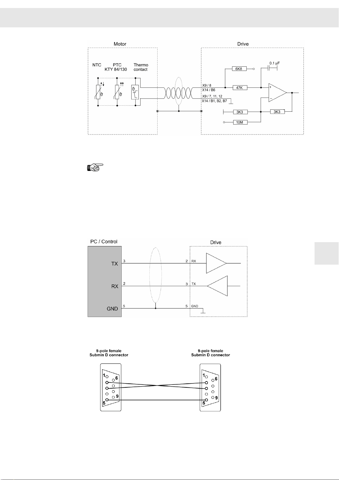
9.5 X9/X14 – Temperature Sensor of the Motor
INPUT/OUTPUT: The thermal motor protection is evaluated via these connectors.
The drive amplifier supports evaluating the temperature monitoring integrated in the
motor. The NTC/PTC behavior of the monitoring is defined in the software (motor para‐
meters). The controller is deactivated as soon as the critical motor temperature is
reached.
You can configure “None”, “PTC / Thermo switch”, “NTC”, “KTY84/130”, “KTY83/122”
and “PT1000”.
50 Drive Amplifier SD2B / SD2B plus - Hardware Description
Page 51
W
Connection Examples
The temperature sensor must have an internal resistor between 250 Ω and 2 kΩ.
If no motor temperature sensor is connected, the input must be connected
with GND.
9.6 X10 – Bus Connection
9.6.1 COM1 – RS232
If you connect X10 to a standard RS232 interface of a PC (9-pole male submin D
connector), the used cable must look like this:
9
Drive Amplifier SD2B / SD2B plus - Hardware Description 51
Page 52

Connection Examples
Additional RS232 connection available:
9.6.2 CAN Bus
The CAN interface is designed according to ISO 11898. It is a two-wire connection with
differential signals. ISO 11898 specifies a bus cable with two signal lines, CAN_H and
CAN_L. The lines have a rated impedance of 120 Ohm. The signal lines are connected
to a terminating resistor (120 Ohm) at both ends of the bus cable (see figure).
W
9
The total length of the bus cable must not exceed the specified lengths. The following
table indicates physical limitations valid for specific transmission rates:
Baud rate
50 kBd 1000 m
125 kBd 500 m
250 kBd 250 m
500 kBd 100 m
1000 kBd 25 m
The number of bus nodes is also limited by the specification according to ISO 11898.
The limiting value is between 32 and 100 bus nodes. depending on the used cable and
transmission rate. For further information on the maximum number of bus nodes refer
to the document “CAN Physical Layer” by the user organization CiA e. V.
Max. bus length
52 Drive Amplifier SD2B / SD2B plus - Hardware Description
Page 53
W
Connection Examples
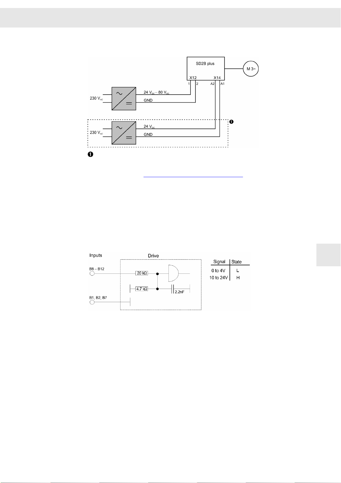
9.7 X12/X14 – DC Power Supply Unit
The logic supply at X14 is required under the following conditions:
▶ maintaining the error messages after switch-off is desired
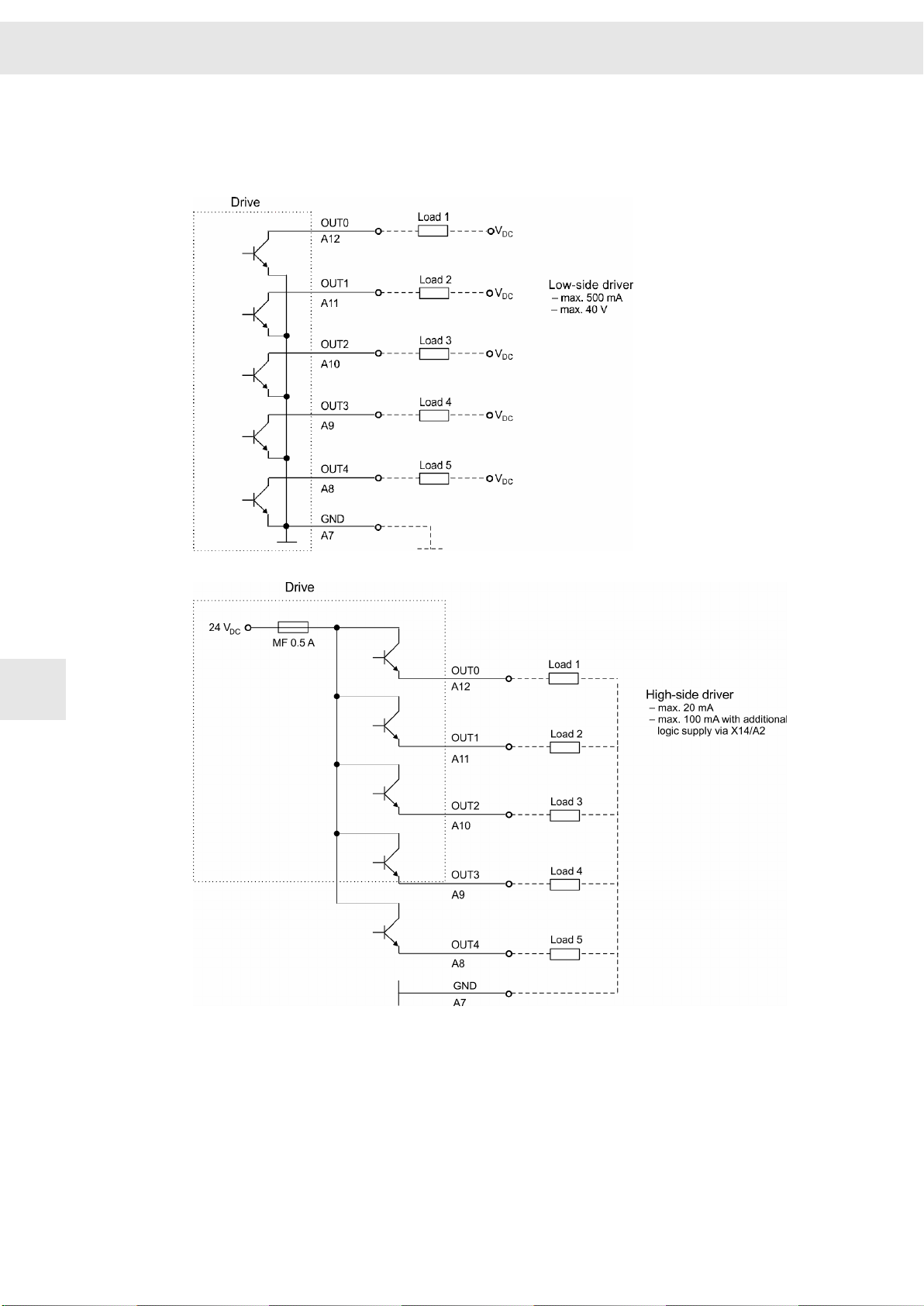
▶ higher output currents of the digital outputs (> 20 mA), see connection
example section 9.8.2 "Digital Outputs", page 54
9.8 X14 – In/Out / STO
9.8.1 Digital Inputs
The meanings of the digital inputs can be defined by parameters.
9
Drive Amplifier SD2B / SD2B plus - Hardware Description 53
Page 54
Connection Examples
9.8.2 Digital Outputs
The output driver can operate as low-side driver or as high-side driver. You can set the
desired driver type in the software
drivemaster2
W
.
9
54 Drive Amplifier SD2B / SD2B plus - Hardware Description
Page 55

W
9.8.3 Analog Input
Voltage interface with input voltage range: ±10 V
Connection Examples
Can also be connected to potentiometer (500 Ω – 5 kΩ)
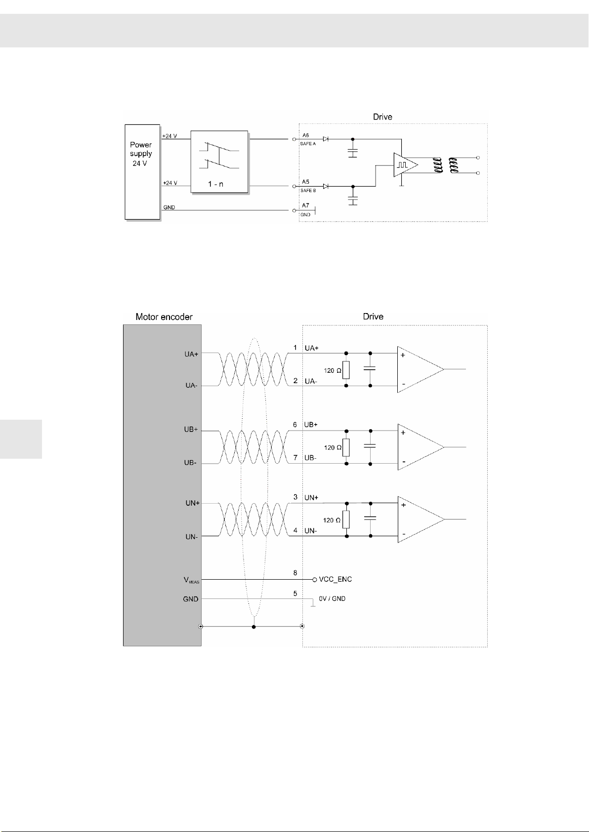
9.8.4 safety circuit (STO)
See also chapter 13 "Safety Circuit / Restart Lock (STO)", page 75.
9.8.4.1 Wiring with OSSD
OSSD = Output Signal Switching Device
9
Drive Amplifier SD2B / SD2B plus - Hardware Description 55
Page 56
Connection Examples
9.8.4.2 Wiring without OSSD
OSSD = Output Signal Switching Device
9.9 X15, X16 – Incremental Encoder with TTL Signals
W
9
Encoder signals: 5V
56 Drive Amplifier SD2B / SD2B plus - Hardware Description
Page 57
W
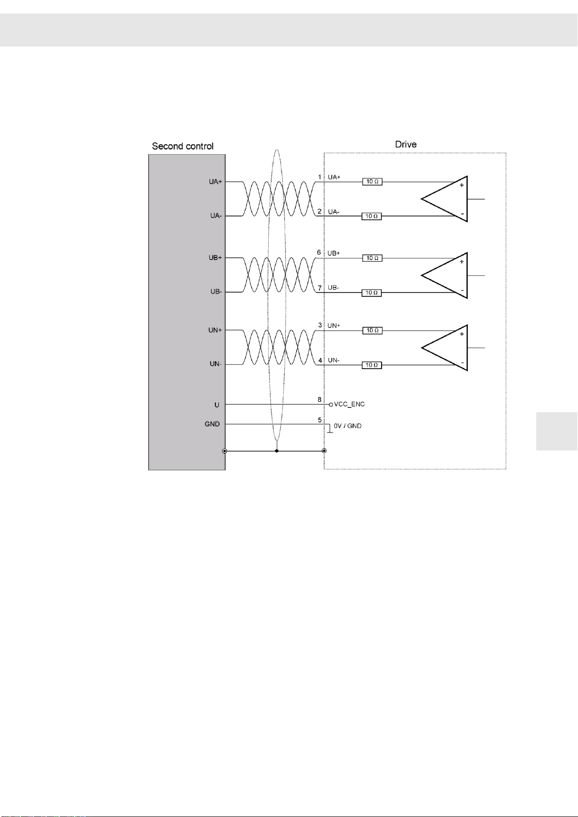
9.10 X16 – ENC1/EMU
9.10.1 Encoder Emulation
Connection Examples
The transmission meets the requirements of the standard TIA/EIA-422-B with a voltage
differential of at least. ±0.9 V.
9
Drive Amplifier SD2B / SD2B plus - Hardware Description 57
Page 58

Connection Examples
9.10.2 Hall Sensor 5.3 V
W
9
9.10.3 PULSE IN 5.3 V
58 Drive Amplifier SD2B / SD2B plus - Hardware Description
Page 59

W
Status Display and Error Messages
10 Status Display and Error Messages
The 7-segment display shows status and error messages.
A status message is made up of 1 to 5 digits and displayed as sequence. All messages
end with dot behind the last digit. When the first digit is 'E.', there is a permanent error.
If the cause of an error can be specified, the display indicates the actual error code
followed by a hyphen and a one-digit sub error code.
Devices with older firmware do not feature the sub error code.
Examples:
1. Permanent display 0
▶ Controller is switched off.
▶ No error.
2.
3.
4.
5.
6.
7.
8.
Permanent display 1
Permanent display 1.
→ →
→ →
→ → → →
→ →
→ →
Sequential display
Sequential display
Sequential display
Sequential display
▶ Controller is switched on.
▶ No error.
▶ Controller is switched on.
▶ No error.
▶ Dot calls additional attention to PI limit.
▶ Controller is switched off due to error E40.
▶ The error is not present anymore.
▶ Controller is switched off due to error E40.
▶ The error is still present (indicated by the dot
behind 'E').
Sequential display
▶ Controller is switched off due to error E11.
▶ The error is still present (indicated by the dot
behind 'E').
▶ Sub error code 4 is indicated as cause.
▶ Controller is in boot loader mode: Display appears
short-time when the device is booted and when
the system software is loaded.
▶ Drive address: During booting of the devices the
set address of the drive is displayed short-time
(here A01)
10
10.1 List of the Operating States
Code
0 Ready to switch on
1 Controller active
1. Controller active, controller is limited / PI limit
2 Mains 'Ready for operation' not present yet
L Boot loader active (during boot / software load)
Drive Amplifier SD2B / SD2B plus - Hardware Description 59
Description
Page 60

Status Display and Error Messages
10.2 List of Drive Error Messages
The following messages apply to the entire SD2x drive series. According to
the device type or operating mode, certain messages may not appear.
Code Error message Error reaction Possible reason
W
E03
(0x103)
(259d)
E05
(0x105)
(261d)
E06
(0x106)
(262d)
E07
(0x107)
(263
d
Interpolation error (interpolated
position control)
1 Acceleration limit exceeded
2 Speed limit exceeded
3 Index error
Error caused by warning
Digital Input 'External Hardware'
0 Digital input 0 Digital input “External Hardware
1 Analog input 0: broken cable 1 Minimum current monitoring of
2 Analog input 1: broken cable 2 Minimum current monitoring of
3 Analog input 0 and 1: broken
cable
Error in internal hardware
)
Motor is stopped by quick stop
ramp and drive is disabled
(controlled standstill).
Motor is stopped by quick stop
ramp and drive is disabled
(controlled standstill).
Motor is stopped by parameterdriven ramp and drive is disabled
(controlled standstill).
Motor is stopped by quick stop
ramp and drive is disabled
(controlled standstill).
▶ Faulty motion profile of the higher-
ranking control
▶ Parameter-driven monitoring
stopped the drive.
Monitoring of external hardware:
OK” is not connected to 24 V.
analog input 0 has triggered.
analog input 1 has triggered.
3 Minimum current monitorings of
analog inputs 0 and 1 have trig‐
gered.
▶ Overload in digital outputs
▶ SD2B plus: Operating voltage not
available
10
E09
(0x109)
(265
d
E10
(0x10A)
(266
d
E11
(0x10B)
(267
d
Hiperface / EnDat OEM data
incorrect
)
drive-setup-tool heartbeat
)
Communication / bus system error
1
▶
SERVOLINK 4
)
2
▶
DNC 8 Byte
3
▶
CAN bus
4
▶
EtherCAT
1
Faulty telegram ID
2
Zero data telegram
3
CRC error
4
Synchronization error
5
Configuration error
6
NMT error
7
Addressing error
1
2, 3, 4
4
No "Ready" for startup ▶ Number of motor pole pairs in
Motor is stopped by quick stop
ramp and drive is disabled
(controlled standstill).
Motor is stopped by parameterdriven ramp and drive is disabled
(controlled standstill).
1
1
1, 4
4
EnDat/Hiperface encoder does not
match the parameter set.
▶
drive-setup-tool
communicate with the drive in the
parameterized monitoring time.
Monitoring of bus communication led to
switch-off:
1 Faulty reference value telegram
2 Higher-ranking control not active
3 Check sum error, interferences
during transmission
4 Drive telegram not synchronized
5 Faulty configuration of mailbox,
PDO, watchdog or synchronization
6 Control channel of bus system
was not active during switch-on
(pre-operational)
7 Faulty drive address
was not able to
60 Drive Amplifier SD2B / SD2B plus - Hardware Description
Page 61

W
Status Display and Error Messages
Code Error message Error reaction Possible reason
E12
(0x10C)
(268d)
E15
(0x10F)
(271
d
E17
(0x311)
(785d)
E18
(0x312)
(786d)
E25
(0x319)
(793d)
E26
(0x31A)
(794
d
8
Node Guarding
9
EEPROM error
10
Heartbeat / Watchdog
Mains 'Ready for operation' is
missing
Endat / Hiperface communication
faulty
)
FPGA power output stage shut‐
down
Error in spindle selection
Power supply load too high
Motor temperature too high
)
3
4
2, 3, 4
8 Communication node monitoring:
monitoring time expired (configu‐
rable)
9 Error in EtherCAT EEPROM
10 Heartbeat monitoring: monitoring
time expired (configurable)
Motor is stopped by parameterdriven ramp and drive is disabled
(controlled standstill).
Motor is stopped by quick stop
ramp and drive is disabled
(controlled standstill).
Motor is stopped immediately. ▶ Overload in power supply unit
Motor is stopped immediately. ▶ Spindle selection was not valid at
Drive is stopped by limitation of
motor torque.
Motor is stopped by error ramp
and current limitation.
▶ Power output stage was switched
on, when mains supply was discon‐
nected/interrupted.
▶ Communication of EnDat/Hiperface
is faulty.
“Switch on”.
▶ Output power of drive is greater
than rated power of power supply
unit, since the dimensioning of
drive and motor are not compatible.
▶ Wrong parameters entered for the
motor or wrong dimensioning of the
motor
E27
(0x31B)
(795
d
E28
(0x31C)
(796d)
E29
(0x31D)
(797d)
E30
(0x31E)
(798
d
E31
(0x31F)
(799
d
E33
(0x521)
(1313
E34
(0x522)
(1314
Ambient temperature too high
)
Power output stage temperature
too high
Motor load too high (Motor I²t)
Power output stage load too high
(I²t)
)
Speed error or slip too high
)
Power supply load monitoring ->
mains voltage too high
d
)
Power supply load monitoring ->
mains voltage too low
d
)
Motor is stopped by error ramp
and current limitation.
Motor is stopped by error ramp
and current limitation.
Motor is stopped by error ramp
and current limitation.
Motor is stopped by error ramp
and current limitation.
SERVO / VECTOR: Drive is
limited by current monitoring via
short-circuit of the motor phases.
(1)
HSPWM: Drive is stopped by error
ramp and current limitation.
Power supply unit will be discon‐
nected from mains.
Power supply unit will be discon‐
nected from mains.
(1)
(1)
▶ Insufficient device cooling
▶ Insufficient cooling of power output
stage (heat sink)
▶ Average motor load is too high due
to mechanical problems
▶ Wrong dimensioning of the motor
▶ Average load of output stage is too
high due to mechanical problems
▶ Wrong dimensioning of the drive
▶ Motor is not able to comply with the
set speed (e.g. defective motor,
mechanical problems, wrong para‐
meters), failure of the measuring
system
▶ Parameterized mains voltage does
not match the connected voltage
▶ Device connected incorrectly
▶ Heavy fluctuation of the power
supply towards overvoltage
▶ DC link was not precharged to the
minimum voltage level in the set
time period; mains voltage is
connected to the short-circuited DC
link
10
Drive Amplifier SD2B / SD2B plus - Hardware Description 61
Page 62

Status Display and Error Messages
Code Error message Error reaction Possible reason
W
E35
(0x523)
(1315d)
E36
(0x524)
(1316
E37
(0x525)
(1317d)
E37
(0x525)
(1317
E38
(0x526)
(1318d)
E39
(0x527)
(1319d)
Error in external power supply unit
Encoder 0 monitoring
d
)
Ballast circuit load (I²t ballast
resistor)
1 I²t 1 Wrong dimensioning, too much
2
(VCE) desaturation detection
or: DC DC converter over‐
load
(only 0362144xy)
Drive is immediately disabled,
motor coasts to standstill.
Motor is stopped by current moni‐
toring via short-circuit of the motor
phases.
Drive is immediately disabled,
motor coasts to standstill.
▶ Error message from external power
supply unit; power supply is
switched off.
▶ Connection of encoder 0 is faulty
▶ Broken cable
Ballast circuit load due to:
energy supplied to R
cable, no bridge at R
ext.)
2
Bridge at R
short circuit of insulation etc.
Or: internal hardware fault
is not correct,
Ballast
0362144xy)
DC DC converter overload
0362161xy)
d
)
Actual speed value greater than
overspeed threshold
Tracking error monitoring and
motor slowdown
(only
Power supply unit will be discon‐
nected from mains.
Motor is stopped by current moni‐
toring via short-circuit of the motor
(1)
phases.
Motor is stopped by current moni‐
toring via short-circuit of the motor
(1)
phases.
▶ Overload at voltage converter of
DC link
▶ Wrong parameters
▶ Motor connected incorrectly
▶ Wrong parameters
▶ Motor connected incorrectly
▶ Mechanical problems
Ballast
Ballast
, broken
(int./
(only
10
E40
(0x528)
(1320
E41
(0x529)
(1321
E42
(0x52A)
(1322d)
E43
(0x52B)
(1323
E44
(0x52C)
(1324d)
Motor feedback
d
)
Motor phase lost
1 No motor connected 1 No motor connected / incorrect
d
)
2 Wrong motor connected 2 Wrong parameters
Overvoltage in DC link
Undervoltage in DC link
d
)
Commutation lost
The following list of error
messages includes a note for
which drive function the error
might appear.
1
▶
HSBLOCK
2
▶
FPAM
3
▶
SVC
4
▶
HSPWM
5
▶
VF
Motor is stopped by current moni‐
toring via short-circuit of the motor
(1)
phases.
Motor is stopped by current moni‐
toring via short-circuit of the motor
(1)
phases.
Drive is immediately disabled,
motor coasts to standstill.
Drive is immediately disabled,
motor coasts to standstill.
Drive is immediately disabled,
motor coasts to standstill.
▶ Connection of motor feedback
faulty
▶ Broken cable
Motor connection/configuration is faulty:
wiring, broken cable
▶ No ballast resistor is connected or
ballast resistor is dimensioned too
small, i.e. X41/X63 not connected
▶ DC link not connected
The error E44 is triggered in case of
wrong current feed of the motor during
operation without sensor.
Possible reason: wrong parameter
setting or overload of the motor. The
error depends on the drive function. For
details refer to the corresponding setup
instructions.
1
EMF monitoring
2
Flux monitoring
3
Over current monitoring
1, 2, 3 4
4
4
62 Drive Amplifier SD2B / SD2B plus - Hardware Description
Page 63

W
Status Display and Error Messages
Code Error message Error reaction Possible reason
E45
(0x52D)
(1325d)
E46
(0x52E)
(1326d)
4
Under flux monitoring
5
Minimum speed monitoring
2, 3
6
Error during alignment
7 Current limitation V/f oscil‐
Short circuit in power output stage
1 Internal short circuit 1 Faulty drive control
2 (VCE) desaturation detection 2 Wrong parameters, output stage
3
4 Current measuring range 4 Wrong parameters, output stage
5
1
5
lates
Short to ground 3 Short to ground of a motor phase
Overload motor 5 Drive function V/f: incorrect para‐
Safety circuit (Safety X10) Drive is immediately disabled,
4
1 ,
1, 2
Drive is immediately disabled,
motor coasts to standstill.
motor coasts to standstill without
control.
Short circuit of the power output stage
due to:
defective, broken cable, short
circuit etc.
defective, broken cable, short
circuit etc.
meter setting of “Flying restart”
1
Safety circuit STO is activated
when the output stage is active;
input SAFE A and/or input SAFE B
were triggered.
2
Initialization error: internal
hardware of safety controller
3
Incorrect data/parameters in
process sequence
4 Error in function parameters
for a functional part
5 Timeout of monitoring func‐
tions
6
Monitoring of OSSD signals
and output stage enable
7
Monitoring of motor phases 7 Safety function SFM/SLOF: defec‐
8 Frequency exceeded 8 Safety function SFM/SLOF:
2 Safety function SFM/SLOF: error
in according hardware compo‐
nents of the safety controller
3 Safety function SFM/SLOF: faulty
PLC telegrams
4 Safety function SFM/SLOF: para‐
meter is out of limits
5 Safety function SFM/SLOF: error
in according hardware compo‐
nents
6 Safety function SFM/SLOF:
▶ wrong OSSD signals
▶ defective OSSD relay
▶ defective multiplexer
tive motor cable (broken cable)
▶ set reference speed value is
too high
▶ limit value for Safe Limited
Output Frequency is parame‐
terized incorrectly
▶ OSSD signals are set incor‐
rectly
10
9 Communication error
between DSP and safety
controller
9
Safety function SFM/SLOF:
communication between DSP and
safety controller is disturbed
Drive Amplifier SD2B / SD2B plus - Hardware Description 63
Page 64

Status Display and Error Messages
Code Error message Error reaction Possible reason
W
E47
(0x52F)
(1327d)
E55
(0x737)
(1847
E56
(0x738)
(1848
E57
(0x739)
(1849
E58
(0x73A)
(1850d)
E59
(0x73B)
(1851
E60
(0x73C)
(1852d)
E61
(0x73D)
(1853d)
Drive parameters not activated
Firmware stopped by ESC
d
)
Device configuration
d
)
Faulty or no firmware
d
)
FPGA watchdog triggered
No drive parameters loaded
d
)
Drive parameters incorrect
Logic coding missing or incorrect
Power output stage can not be
activated.
Device stops in BIOS. ▶ During boot-up the device received
Device stops in BIOS. ▶ During boot-up the device detected
Device stops in BIOS. ▶ During boot-up the device detected
Device stops in BIOS. ▶ FPGA process monitoring has
Device stops in BIOS. ▶ Device is not parameterized (status
Device stops in BIOS. ▶ Parameter set of the device is not
Device stops in BIOS. ▶ Logic programming of the device is
▶ Drive start is not acknowledged by
master yet (configurable by
parameters in software).
an ESC sequence at the serial
interface.
that hardware, firmware parame‐
ters and logic are not consistent; a
detailed error description is
received by a parameter download.
no firmware or a faulty firmware.
been triggered; please contact
SIEB & MEYER.
of delivery).
valid (CRC error).
not valid.
10
E62
(0x73E)
(1854d)
Error in electronic type plate
(1)
For servo motors with commutation via an incremental motor measuring system the warning W17
“Unknown commutation angle ” is signaled. After a restart of the device the phasing of the motor measuring
system starts automatically (magnetic alignment).
Device stops in BIOS. ▶ Type plate is not programmed or
10.3 List of Warning Messages
Warning messages are not displayed on the device display. They can only be seen in
the software
Code
W00 Digital input 'Quick stop' active
W01 Digital input 'Positive limit switch' active
W02 Digital input 'Negative limit switch' active
W03 Voltage of mains supply not OK
W04 Power output stage load greater than parameterized warning threshold W04 (power output
W05 Motor load greater than parameterized warning threshold W05 (motor I²t)
W06 Power output stage temperature greater than parameterized warning threshold W06
W07 Motor temperature greater than parameterized warning threshold W07
W08 DC link voltage greater than parameterized warning threshold W08
W09 DC link voltage less than parameterized warning threshold W09
W10 Speed controller in current limitation / PI limit
drivemaster2
Description
stage I²t)
via “Diagnosis ÿ Errors and warnings”.
faulty; please contact
SIEB & MEYER.
64 Drive Amplifier SD2B / SD2B plus - Hardware Description
Page 65
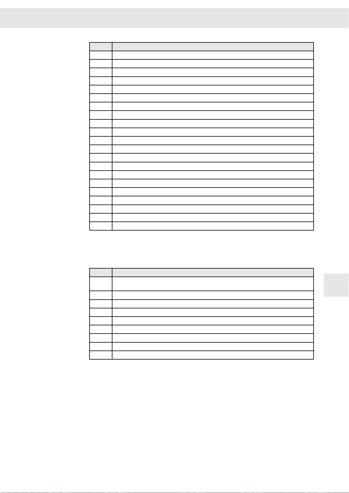
W
Status Display and Error Messages
Code Description
W11 Position/tracking error greater than parameterized warning threshold W11
W12 Speed error greater than parameterized warning threshold W12
W13 Tracking error of the current too great
W14 Ambient temperature greater than parameterized warning threshold W14
W15 Ballast resistor load greater than parameterized warning threshold W15 (ballast resistor I²t)
W16 Safety circuit is active
W17 Unknown commutation angle
W18 Hiperface / EnDat OEM data not valid
W19 Dirt signal encoder input 0
W20 Dirt signal encoder input 1
W21 Dirt signal encoder input 2
W22 Power supply unit load greater than 90% of the rated power
W23 Reserved
W24 Current or current rise greater than warning threshold W24 (warning current)
W25 Reference speed less than minimum motor speed
W26 Current greater than warning threshold W26 (warning overload current)
W27 Reserved
W28 Reserved
W29 Reserved
W30 Reserved
W31 Reserved
10.4 Message of the Quick Stop Functions
Code
H01 Digital input "Switch on" waits for positive edge to switch the drive on (This function is only
H03 Software function "Quick stop"
H04 Digital input "Quick stop"
H07 Software positioning error "Negative limit"
H08 Software positioning error "Positive limit"
H09 Bus system "Quick stop" (The quick stop bit is set to 0)
H11 Digital input "Negative limit switch"
H12 Digital input "Positive limit switch"
H13 Digital input "Speed Enable"
Description
active when the input is set as "Switch on type 2 (with positive edge)".)
10
Drive Amplifier SD2B / SD2B plus - Hardware Description 65
Page 66

Status Display and Error Messages
W
10
66 Drive Amplifier SD2B / SD2B plus - Hardware Description
Page 67

W
General Information Regarding the Wiring
11 General Information Regarding the
Wiring
11.1 Cable Requirements
The cables described in this chapter meet the SIEB & MEYER requirements for cables
and connectors in order to ensure their proper function.
NOTICE
Risk of cable damage due to mechanical loads
Cables that are exposed to mechanical loads, e.g. trailing chains or similar, must
be suited for this purpose. Otherwise, damage may occur. SIEB & MEYER cables
are not suitable for trailing chains!
The machine manufacturer must ensure that only cables are used that are suitable
for this purpose.
In general, the following principles apply for the cables (see also documentation “Unit
Assembly Complying EMC”)
▶ Motor and signal cables must not be wired in the same cable protection hose!
▶ Motor cables must have a wire-meshed shield. They must be wired separately
from signal cables.
▶ Signal lines must have a wire-meshed shield. Differential signals should only be
transmitted with twisted-pair lines. They must be wired separately from motor
cables.
▶ The cable shields must be connected to the connector shell inside of the connec‐
tors. In the switch cabinet they should be connected to a ground bus.
▶ Cable shields not ending in a connector inside of the switch cabinet such as motor
cables must be connected to the ground bus.
▶ Both ends of the shield of shielded cables must generally be connected to the
shell.
11
The line cross-sections should be selected carefully: The maximum admissible current
should not be exceeded at the maximum ambient temperature (see technical data).
DIN VDE 0298-4 defines the admissible values for the individual line cross-sections
which must absolutely be taken into account.
The current carrying capacity in connection with the line cross-section of copper
conductors isolated with PVC or cables according to DIN VDE 0298-4 for different
types of wiring are indicated in the following table: All values are related to an ambient
temperature of +40 °C and an operating temperature at the conductor of 70 °C.
Conductor cross-
section A [mm²]
0.75 7.6 10.4 –
1.00 9.6 12.4 –
1.50 12.2 16 –
2.50 16.5 22 –
4 23 30 –
Drive Amplifier SD2B / SD2B plus - Hardware Description 67
B2 wiring
(1)
Admissible current I [A]
E wiring (3 cable leads)
(2)
F wiring (3 cable leads)
(3)
Page 68

General Information Regarding the Wiring
W
Conductor cross-
section A [mm²]
6 29 37 –
10 40 52 –
16 53 70 –
25 67 88 96
35 83 110 119
50 100 133 145
70 130 171 188
95 150 207 230
120 175 240 268
150 – 277 309
185 – 317 356
240 – 374 422
300 – 433 488
400 – – 570
500 – – 652
630 – – 744
(1)
B2 wiring: wiring in installation tubes or closed installation channels.
(2)
E wiring: Free wiring of one cable with a min. distance of 0.3 × cable diameter to the wall.
(3)
F wiring: Free wiring of several cables with a min. distance of 1 × cable diameter to the wall.
Tab. 2: Current carrying capacity according to DIN VDE 0298-4
B2 wiring
(1)
Admissible current I [A]
E wiring (3 cable leads)
(2)
F wiring (3 cable leads)
(3)
11
For detailed information refer to the standard IEC 60364-5-52 and the documents of
the cable manufacturer.
The following correction factors are provided for deviating ambient temperatures:
Ambient temperature T [°C]
30 1.15
35 1.08
40 1.00
45 0.91
50 0.82
55 0.71
60 0.58
Correction factor
Cross-sections of round conductors
The standard values of the cross-section of round copper conductors as well as the
approximate ratio of metric ISO and AWG/MCM values are shown in the following
table.
Standardized cross-sections of round conductors:
ISO cross-section [mm²]
Value Equivalent cross-section [mm²]
0.2 24 0.205
– 22 0.324
0.5 20 0.519
0.75 18 0.82
AWG/MCM
68 Drive Amplifier SD2B / SD2B plus - Hardware Description
Page 69

W
General Information Regarding the Wiring
ISO cross-section [mm²] AWG/MCM
Value Equivalent cross-section [mm²]
1.0 – –
1.5 16 1.3
2.5 14 2.1
4.0 12 3.3
6.0 10 5.3
10 8 8.4
16 6 13.3
25 4 21.2
35 2 33.6
50 0 53.5
70 00 67.4
95 000 85.0
– 0000 107.2
120 250 MCM 127
150 300 MCM 152
185 350 MCM 177
240 500 MCM 253
300 600 MCM 304
The line corresponds to a value when the connection possibilities are taken
into account.
11.1.1 Motor Cable
DANGER
Dangerous shock currents
Earthing and shielding measures are required to protect devices and persons. To
ensure the safety of the operator earthing must be carried out with low impedance.
With respect to the ground connection one of the following actions must be done:
▶ connect the motor housing to the ground of the machine or
▶ connect the ground terminal of the motor connector to the central ground point
of the machine.
Consider the following with regard to shielding: Always use shielded motor cables!
11
Drive Amplifier SD2B / SD2B plus - Hardware Description 69
Page 70

General Information Regarding the Wiring
W
NOTICE
Disturbing ground loops
Incorrect connection of protective earth connections in motor cables may cause
disturbing ground loops and malfunction of the motor.
Connect the protective earth conductors additionally led in motor cables directly to
the shield line and label them with T or PE.
If the procedure turns out to be impracticable, omit the earth conductor connection
in the motor cables and wire a separate earth conductor in parallel to the motor
cables.
Ensure that the cable is returned to the drive! Do not wire the cable with another
ground loop.
✔ The described measures prevent disturbing ground loops.
Use shielded cables for the motor in order to keep interference as low as possible.
The cable shield must be connected large-area with 360° shield termination. In addi‐
tion, the motor cable should be as short as possible to reduce electromagnetic radia‐
tion and capacitive currents.
11
Fig. 11: Motor connection
Requirements to the motor cable
The maximum admissible length of the motor cable is 100 m. The capacity must not
exceed 5.2 nF.
Example: If the cable capacity is 0.26 nF per meter, the maximum admissible length of
the motor cable is 20 m.
70 Drive Amplifier SD2B / SD2B plus - Hardware Description
Page 71

W
Electric Performance Dimensioning
12 Electric Performance Dimensioning
Experience shows that questions arise during the dimensioning of a drive when
selecting output stages and power supplies. This chapter shall make clear the physical
background and shall help to dimension correctly the electronic components.
12.1 Components
The following sections provide information on the electric performance dimensioning of
the drive components (output stage, power supply unit and motor).
12.1.1 Output Stage
The output stage of a drive amplifier is specified by the following details:
Voltage range
The maximum DC link voltage is limited by the used transistors and capacitors and the
minimum space between the strip conductors.
When an output stage with a maximum admissible DC link voltage of 325 VDC (class
C) is used, i.e. with an AC power supply of 230 VAC, the components will have an elec‐
tric strength of 600 VDC. The reserve is necessary in order to prevent damage in the
case of voltage peaks and the DC link voltages during the deceleration.
Current range
The current range specifies the maximum admissible currents. Distinction is made
between peak and rated current:
▶ The peak current is only admissible for a short time (mostly 5 seconds) and
depends on the used transistors and their number.
▶ The rated current can be provided continuously by the output stage. Its value
depends on the cooling of the transistors, that means: the capacity of the used
heat sink and its ventilation.
▶ Due to the higher load of the power semiconductors in the output stage during a
static rotating field or low rotating field frequencies (f ≤ 5 Hz) the rated current will
be reduced by the factor √2 within this frequency range for the SIEB & MEYER
devices of the series SD2, SD2S and SD2T.
12
12.1.2 Power Supply
The power supply is specified by the following details:
Voltage range
The maximum supply voltage is limited by the used transistors, diodes and capacitors
and the minimum space between the strip conductors.
Drive Amplifier SD2B / SD2B plus - Hardware Description 71
Page 72

Electric Performance Dimensioning
Current range
The current range specifies the maximum admissible currents. Distinction is made
between peak and rated current:
▶ The peak current is only admissible for a short time (mostly 1 second) and
depends on the used diodes and their number.
▶ The rated current can be provided continuously by the power supply unit. Its value
depends on the cooling of the diodes, that means: the capacity of the used heat
sink and its ventilation.
Power
In practice, a maximum permanent power is specified for power supply units, since the
supply voltage is assumed to be constant. As the limitation in the power supply unit is
determined by the load carrying capacity of the diodes, the maximum permanent
power depends on the supply voltage and the type of supply.
Examples:
▶ Power supply 230 VAC, 2 phases, max. permanent current of the diodes 6 A
230 VAC × 2 × 6 A = 2.76 kW
▶ Power supply 400 VAC, 3 phases, max. permanent current of the diodes 6 A
400 VAC × 3 × 6 A = 7.20 kW
W
12
The maximum peak current depends on the type of diode used.
The protection is calculated as follows:
12.1.3 Motor
The motor is specified by the following details:
Peak current
The peak current defines the max. allowed motor current. The peak current is only
allowed for a short period of time (between 1 and 30 Sekunden) and depends on the
used magnetic material and the thickness of the windings. Normally, the motor manu‐
facturer defines the peak current applying during downtimes and during a rotating field.
Generally, the values given on the motor data sheet are RMS values. SIEB & MEYER
specifies currents as sine peak amplitudes.
The RMS values are calculated by dividing these values by the factor √2.
Rated current
The rated current can be applied permanently to the motor. The value depends on the
cooling of the motor, the windings and the max. allowed motor temperature. Normally,
the motor manufacturer defines the rated current applying during downtimes and
during a rotating field. Generally, the values given on the motor data sheet are RMS
values. SIEB & MEYER specifies currents as sine peak amplitudes.
The RMS values are calculated by dividing these values by the factor √2.
The current version of the software drivemaster2 allows switching between the RMS
value and the sine peak amplitude (see “Settings ÿ Program settings ÿ View”).
When switching the view, the existing values are automatically converted into the new
unit. The default setting is the RMS value.
72 Drive Amplifier SD2B / SD2B plus - Hardware Description
Page 73

W
Electric Performance Dimensioning
Motor voltage
The motor voltage is the voltage directly available at the motor. The value of the motor
voltage depends on the used electric components. In case of a three-phase power
supply with power choke, controlled drive amplifier and a motor choke, voltage drops of
approx. 4 %, 8 % and 1 % of the mains voltage will result. Additional voltage losses of
approx. 2 % can be observed in a soft net.
Example
The following example uses a controlled drive amplifier with a mains choke at a mains
voltage of 400 V. The following motor voltage will result:
U
= 400 V − (400 V * 12 %) = 352 V
Motor
Voltage constant
Due to its inductance the motor generates a countervoltage which is opposite to the
supplied voltage. This voltage is proportional to the speed and defined in 'volt per
1000 revolutions'. Generally, the values are RMS values measured between the
connection pins.
Example
▶ DC link voltage: 325 V
▶ e.m.f.: 1000 mV/min
A voltage of only 225 V is available to control the motor at 1000 rpm. The theoretical
max. speed of the motor is 3250 rpm. At this speed no torque will be available
anymore, since no current can be applied anymore.
Torque constant
The torque constant specifies the relation between the motor current and the motor
torque (Nm/A). The torque constant results from the required max. speed, dynamic
characteristics, efficiency and the quality of the magnetic material.
Inductive winding resistance
The inductive winding resistance (ωL) is the result of the individual number of windings
of the total winding. During period of downtimes the resistance is zero. It increases with
the frequency.
Ohmic winding resistance
The ohmic winding resistance R is the results from the length and the thickness of
wire. During periods of downtimes it specifies the winding resistance alone.
Electric time constant
The elctric time constant is the quotient of the inductive and ohmic resistance (τ = L/R).
12
Motors for tightening systems
Generally, motors for tightening systems are high-dynamic motors characterized by
high maximum speeds, high peak torque values, low inertia of masses and small rated
torque values. This results in a small voltage constant, small inductance values, thin
windings and low rotor diameters. Due to the low inductance value motors in tightening
systems are operated at a high pulse with modulation frequency (PWM frequency
16 kHz) to keep the current ripple as small as possible.
Drive Amplifier SD2B / SD2B plus - Hardware Description 73
Page 74

Electric Performance Dimensioning
12.2 Power Consumption of a Drive
If a constant torque is taken from the drive, the power consumption will depend on the
current speed.
Examples:
▶ Preset torque: 30 Nm
▶ DC link voltage: 300 V
▶ Voltage constant: 50 mV / min (50 V / 1000 rpm)
▶ Coil resistance: 1 Ω
▶ Torque constant: 1 Nm / A
From this results a motor current of:
The motor requires a voltage of V = 1 Ω × 30 A = 30 V
0 rpm, standstill
W
12
From this results a power of P = 30 V × 30 A = 0.9 kW.
At a DC link voltage of 300 V an input current results from the supply voltage of
I = P / 300 V = 3 A.
Thus, considerably less current flows in the power supply unit than in the motor. This
calculation is very important especially for nut setting applications, since the high
torques and thus currents are only required for low speeds.
2000 rpm
At 2000 rpm the motor requires a voltage of V = R × I + e.m.f. × n =
1 Ω × 30 A + 50 V / (1000 rpm) × (2000 rpm) = 130 V.
From this results a power of P = 130 V × 30 A = 3.9 kW.
At a DC link voltage of 300 V an input current results from the supply voltage of
I = P / 300 V = 13 A.
Thus, a considerable higher current flows in the power supply at a speed of 2000 rpm
than at standstill.
5400 rpm
At 5400 rpm the motor requires a voltage of V = R × I + e.m.f. × n = 1 Ω × 30 A + 50 V /
(1000 rpm) × (5400 rpm) = 300 V.
From this results a power of P = 300 V × 30 A = 9 kW.
At a DC link voltage of 300 V an input current results from the supply voltage of
I = P / 300 V = 30 A.
Thus, the same current flows in the power supply unit and in the motor at a speed of
5400 rpm. It must be considered that the currents flowing in the motor phases are
lower by factor √3 than the currents calculated above.
The examples clearly show that the expected motion profile must be considered when
dimensioning the power supply unit. An exact dimensioning can only be achieved by
integrating the motion profile.
The same applies for conceiving the output stage and the motor.
74 Drive Amplifier SD2B / SD2B plus - Hardware Description
Page 75

W
Safety Circuit / Restart Lock (STO)
13 Safety Circuit / Restart Lock (STO)
▶
according to EN ISO 13849-1:2008-12, DIN EN 62061:2005 SIL 3
The restart lock is provided for preventing an unintentional start of a speed-variable
drive from the standstill and can, for example, be used in the machine function “safe
stop”. It comprises a restart lock tested according to EN ISO 13849-1:2008-12
(VDE 0113) and a stop function according to EN 60204-1:2007-6, stop category 0. A
stop category 1 can be achieved by using a tested, safe emergency stop device with
delay or a safe PLC according to DIN EN 60204-1. The stop functions are defined
according to DIN EN 60204-1 (VDE 0113) paragraphs 9.2.2, 9.2.5.3.
There are three categories of stop functions:
Category 0 Standstill by immediate interruption of the energy supply to the
machine drives, i.e. uncontrolled standstill.
Category 1 The machine is decelerated to standstill without disconnecting
the energy supply between motor and drives (i.e. a controlled
standstill). The energy supply is interrupted at that moment the
machine is at a secure standstill.
Category 2 The energy supply between motor and drives is not interrupted
(a controlled standstill).
Every machine must be equipped with a stop function according to category 0. Stop
functions according to category 1 and/or 2 must be integrated into the machine if they
are necessary for safety and/or operational reasons.
The disadvantages of the disconnection can be eliminated by the consequent use of
electronic elements. The standard EN 60204-1:2007-6 “Safety of machinery - Electrical
equipment of machines” also allows the use of electronic equipment for the stop func‐
tion in case of an emergency, if these – under application of the standardsEN ISO
13849-1:2008-12 and/or DIN EN 62061:2005 – meet the same safety requirements as
required according to DIN EN 60204-1.
This checked safety circuit was conceived according to the concept paper by Drivecom
“Technical Guide for Safety Drives” from 04/23/2004. The concept paper was checked
by the BIA and the TÜV Rheinland: It was confirmed that the required standards and
regulations were met.
The standstill of the machine must be caused by a high-ranking control before and the
stop function of at least category 2 must be ensured.
The restart lock interrupts the energy supply between drive and motor by deactivating
the output stage control. Thus, any rotation of the motor is made impossible.
The advantage of this circuit is that a single drive can be locked safely in an installation
with several drives while other drives remain in operation. Besides, a drive can be
locked without having to charge the DC link electrolytic capacitor at a new restart.
13
Drive Amplifier SD2B / SD2B plus - Hardware Description 75
Page 76

Safety Circuit / Restart Lock (STO)
W
DANGER
Danger due to electric shock
The restart lock does not galvanically separate the output stages from the motor.
Thus, the restart lock does not protect against electric shock.
The complete machine must always be galvanically separated from the mains by
use of the main switch(DIN EN 60204-1 5.3) for any interruptions of the operation,
maintenance, repair or cleaning work at the machine or system.
All mounting locations for safety devices of the control system as well as
components mounted outside have to correspond to an IP code IP54, if
mounted correctly.
13.1 Functional Description of the Restart Lock
The restart lock locks the respective drive of an installation. All further drive modules
(servo amplifiers / frequency converters) remains ready for operation.
A TÜV checked safety circuit accesses relevant control of the output stage transistors
of the drive to be locked by interrupting the voltage supply of the controls. Thus, no
control pulses can be passed on to the transistors of the output stages and the motor is
at a secure standstill.
13
OSSD (Output Signal Switching Device)
Part of the contactless protective unit (German abbreviation = BWS) which is
connected with the machine control and which switches over into the OFF state, when
the sensor unit is triggered during the intended operation. (Source IEC 61496-1).
The OSSD signal is a pulsed signal, of which the phase position is shifted in relation to
the different channels. All error can be detected by checking the pulse pattern, shortcircuit for supply, cross-circuit or defect of the device. This ensures a very high safety
level (SIL 4).
The TÜV checked safety circuit is controlled by the OSSD1+2 signal or via one or
several emergency stop switch devices. See also section 13.2 "Wiring Example",
page 77
76 Drive Amplifier SD2B / SD2B plus - Hardware Description
Page 77

W
Safety Circuit / Restart Lock (STO)
If the OSSD signals or at least one of the +24 V conductors fail, the safety circuit
switches the pulse pattern of the output stage control sectors off. The response time of
the restart lock is max. 4 ms.
The restart lock must only be controlled when
▶ the drive is at a secure standstill (stop category 2),
▶ the higher-ranking control has deactivated the drive module,
▶ (reference speed value 0)
▶ the holding brake of the motor has been arrested.
DANGER
No torque when restart lock is active
The motor cannot provide a torque when the restart lock is activated. Thus nonself-locking drives could be released.
Non-self-locking drives as hanging loads must be blocked with a mechanical
brake.
13.2 Wiring Example
Combining a safe emergency stop command device, an OSSD safety switch device or
a light barrier with OSSD outputs and the safe switching off of the pulse patterns allows
creation of an error detection circuit, which achieves a safe stop (according to stop
function category 0+1), which meets the safety requirements according to SIL 3 (EN
ISO 13849-1). This circuit allows connecting several emergency stop devices in
parallel, which are permanently monitored.
13
Drive Amplifier SD2B / SD2B plus - Hardware Description 77
Page 78

Safety Circuit / Restart Lock (STO)
Circuit with OSSD (SIL 3)
The following figure shows a circuit without OSSD safety device, whilst only safety
directed command devices with forcibly opened contacts in two-channel design are
used. SIL 3 (according to EN ISO 13849-1) is achieved. It is also possible to cascade
several different safe emergency stop devices, position switches or door locks to one
safety circuit.
Circuit without OSSD (SIL 3)
W
13
The safety switch device as well as the emergency stop device have to be
certificated as safety devices of at least level SIL 3 to obtain safety level
SIL 3 according to EN ISO 13849-1.
In order to obtain the safety level SIL 3 according to EN ISO 13849-1the
circuit and the layout have been dimensioned according to IEC
60664-1:2008-01. Supporting material according to IEC 60249 covered by a
nonaging protective coat of lacquer according to IEC 60664-3:2003-09 have
been used. The conformity of standard have been tested and approved by
the TÜV-Nord CERT.
13.3 Requirements and Standards
The following parameters are achieved according to the safety case:
▶ according to EN ISO 13849-1:2008-12
─ MTTFd: >100 years
─ DC = 99%
─ Category 4
─ Performance Level e
▶ according to EN 61508-1:2010 and EN 61800-5-2:2014-06
─ PFH = 0
─ SFF = 100 % (if there are PFH values, then SFF<100%)
─ HFT = 0
78 Drive Amplifier SD2B / SD2B plus - Hardware Description
Page 79

W
Safety Circuit / Restart Lock (STO)
The safety concept K1 meets the requirements of SIL 3 according to the standards
named above.
Requirements according to DIN EN 61800-5-2:2014-06
When connected appropriately, the safety concept K1 does not supply any share of
dangerous, undetected errors in the safety chain for the function STO.
Thus the stop function 0+1 according to EN 60204-1:2007-6 is realized.
Drive Amplifier SD2B / SD2B plus - Hardware Description 79
13
Page 80

Safety Circuit / Restart Lock (STO)
W
13
80 Drive Amplifier SD2B / SD2B plus - Hardware Description
Page 81

W
14 Appendix
14.A Specification of Device Firmware
For the drive amplifiers of the series SD2B / SD2B plus the following firmware is avail‐
able at present.
Firmware F11001vxxxxx UF / SVC
SERVO / VECTOR ✔
Sensorless vector control (SVC), synchronous ✔
HSPAM / VF, asynchronous rotary ✔
Sensorless ✔
Flying Restart ✔
Current-controlled startup ✔
Operating modes
Velocity mode 1 ✔
Control and setpoint channels
Analog + digital inputs ✔
Serial interface / RS485 / USB ✔
CAN bus ✔
DNC 8 Byte ✔
Internal setpoints ✔
Motor Potentiometer ✔
Others
Multi parameter sets ✔
Winding Detection ✔
Field weakening ✔
Current controlled ramps ✔
Appendix
Drive Amplifier SD2B / SD2B plus - Hardware Description 81
14.A
Page 82

Appendix
W
14.A
82 Drive Amplifier SD2B / SD2B plus - Hardware Description
Page 83

W
Appendix B: Manufacturers
14.B Manufacturers
14.B.1 SIEB & MEYER Accessories
In the following you find all accessories for SD2B / SD2B plus that you can order at
SIEB & MEYER.
Consider the information on accessories suitable for your device in the tech‐
nical manual.
14.B.1.1 Connectors of the Series SD2B / SD2B plus
SIEB & MEYER
article number
32299576 Connector kit with mating connectors for motor connection, DC
32299587 Connector kit with mating connectors for motor connection, DC
Description Device variant
power supply, logic and inputs/outputs manufactured by
Phoenix Contact
power supply and inputs/outputs manufactured by Phoenix
Contact
14.B.1.2 Blocking Diode
SIEB & MEYER article number
036210082 Module with blocking diode to decouple the main voltage of SD2B
14.B.1.3 Operating Terminal
SIEB & MEYER article number
0362150 Plug-on operating terminal
0362153 Operating terminal for switch cabinet installation
32299567 Switch cabinet kit for operating terminal 0362150
0362170DB (SD2B)
0362171DB (SD2B
plus)
Description
(0362170DB)
Description
14.B.1.4 USB>RS232/485 Converter 050201
The USB>RS232/485 Converter can be ordered at SIEB & MEYER as an optional
accessory for device configuration. This converter is developed especially for the
amplifier series SD2x. Via the converter the devices can communicate with a PC
without RS232 or RS485 interface.
A short USB cable is supplied with the converter. The connection cable to the drive
amplifiers must be ordered additionally or built by yourself with suitable length.
SIEB & MEYER article number
050201 USB>RS232/485 converter
K362103xxxR01 (xxx = cable
length in dm)
For further information refer to the document “USB_Converter_050-20-1.pdf”.
Drive Amplifier SD2B / SD2B plus - Hardware Description 83
Description
RS232 device connection cable to the converter 050201
14.B
Page 84
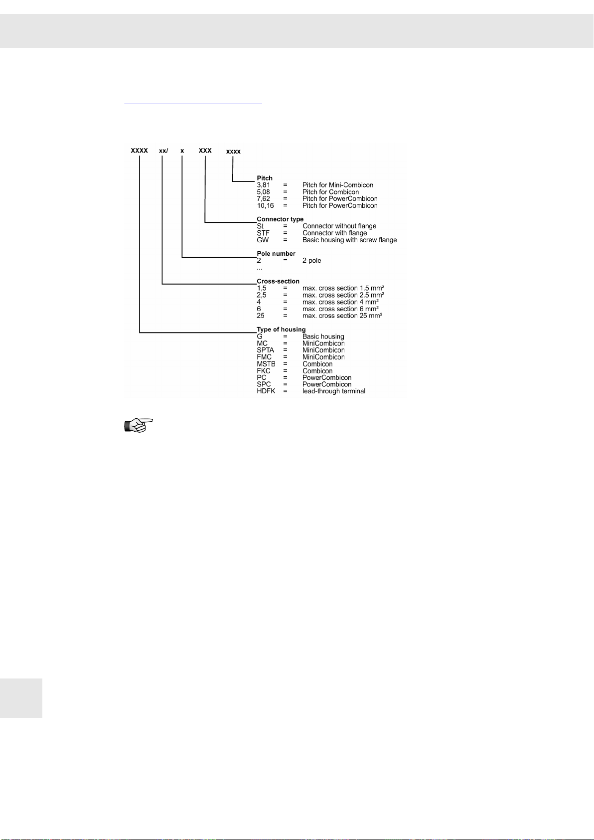
Appendix B: Manufacturers
14.B.2 Phoenix Contact
http://www.phoenixcontact.com
Order key for Phoenix connectors
W
14.B
Labeled connectors can be ordered at SIEB & MEYER.
84 Drive Amplifier SD2B / SD2B plus - Hardware Description
Page 85

W
15 Index
Index
0-9
050201
7-segment display 59
83
A
Accessories
83
B
Block diagram SD2B 28
Block diagram SD2B plus 33
Blocking diode 48
C
Cable requirements 67
D
M
Manufacturers 83
Motor cable 69
Mounting SD2B 29
Mounting SD2B plus 35
O
Operating States 59
OperationSD2B 27
P
Performance dimensioning 71
Push-in technology 39
Q
Quick stop messages 65
Dimensions SD2B
Dimensions SD2B plus 35
29
E
Error messages 60
F
Firmware 81
Functional overview SD2B / SD2B plus
25
I
ID switch
39
L
Line cross-sections
67
R
Residual current device (RCD)
Restart lock 75
S
Spring-cage connection 39
Status display 59
STO (Safe Torque Off) 75
T
Technical data SD2B
Technical data SD2B plus 36
Type plate 23
30
U
USB>RS232/485 converter 83
18
W
Warning messages
Drive Amplifier SD2B / SD2B plus - Hardware Description 85
64
15
Page 86

Index
W
Wiring instructions 67
X
X10 – COM1 / operating terminal 42
X11 – USB 43
X12 – DC input 43
X13 – motor 44
X14 – IN/OUT 44
X15 – ENC0 45
X16 – ENC1/EMU 46
X2 – motor 40
X4 – DC input 40
X6 – Logic 41
X9– inputs/outputs 41
15
86 Drive Amplifier SD2B / SD2B plus - Hardware Description
 Loading...