

Page 1
Operating instructions
Series SX602
Alphanumeric large size displays
with Ethernet interface
BAL SX602 ETH EN 3.0
Page 2
MAC address:
: :
:
:
:
Site of the unit:
Germany France
Siebert Industrieelektronik GmbH Siebert France Sarl
Siebertstrasse, D-66571 Eppelborn 33 rue Poincaré, BP 90 334, F-57203 Sarreguemines Cédex
Phone +49 (0) 6806 980-0, Fax +49 (0) 6806 980-999 Phone +33 (0) 3 87 98 63 68, Fax +33 (0) 3 87 98 63 94
www.siebert.de, info@siebert.de www.siebert.fr, info@siebert.fr
Austria Switzerland
Siebert Österreich GmbH Siebert AG
Karl-Eybl-Strasse 4, Postfach 19, A-2435 Ebergassing Bützbergstrasse 2, Postfach 91, CH-4912 Aarwangen
Phone +43 (0) 2234 795 25, Fax +43 (02234) 795 26 Phone +41 (0) 62 922 18 70, Fax +41 (0) 62 922 33 37
www.siebert-oesterreich.at, info@siebert-oesterreich.at www.siebert.ch, info@siebert.ch
© Siebert Industrieelektronik GmbH
®
and LRD® are registered trademarks of Siebert Industrieelektronik GmbH All other product names mentioned herein may be the
Siebert
trademarks or registered trademarks of their respective owners.
Subject to change. – All rights reserved, including the rights of translation. No part of this document may in any form or by any means (print,
photocopy, microfilm or any other process) be reproduced or by using electronic systems be processed, copied, or distributed without our
written permission.
2 BAL SX602 ETH EN 3.0
Page 3

Table of contents
Chapter 1 Safety precautions Important information
Safety
Intended use
Mounting and installation
Battery replacement
Grounding
EMC measures
Disposal
Chapter 2 Unit description Model designation
Unit construction
Display range
Principle circuit diagram
Central Processing Unit
Ethernet interface
Function inputs
Menu display
Status indicator
Ethernet LEDs
Battery
Power supply
Chapter 3 Character display LED matrix
Character sets
Proportional lettering
PC-Tool
LED color
Chapter 4 Control Parameterization
Ethernet interface
Text types
Automatic line break
Automatic paging
Activation commands
Command table
Online texts
Static texts
Initial text
Inserting variables
Deleting text
Forced line break
Flashing
Marquee text
Charater set
LED color
Inserting time/date
Bar graph
$ character
Brightness
Blanking
Reset
Setting time/date
Reading out time/date
BAL SX602 ETH EN 3.0 3
Page 4

Chapter 5 Parameterization Menu display
Menu operation
Menu table
Time-out
Initial text
Paging interval
Charater set
Language
Display test
Network parameters
Time/date
Chapter 6 Configuration MAC Address
Basic configuration
Configuration via network
Additional information
Basic setting
Chapter 7 Status messages Fault messages
Chapter 8 Character table
Chapter 9 Technical data Unit properties
Housing colors
Front frame
Ambient conditions
Max. Power consumption
Fixed text memory
Real-time clock
Chapter 10 Unit measurements and weights Units with one-sided display and
character height of 50 and 100 mm
Units with double-sided display and
character height of 50 and 100 mm
Units with one-side display and
character height of 160 and 250
mm
Units with double-sided display and
character height of 160 and 250
mm
4 BAL SX602 ETH EN 3.0
Page 5
Chapter 1 Safety precautions
Important information Read these operating instructions before starting the unit. They provide you with
important information on the use, safety and maintenance of the units. This helps
you to protect yourself and prevent damage to the unit.
Information intended to help you to avoid death, bodily harm or considerable
damage to property are highlighted by the warning triangle shown here; it is
imperative that this information be properly heeded.
The operating instructions are intended for trained professional electricians familiar
with the safety standards of electrical technology and industrial electronics.
Store these operating instructions in an appropriate place.
The manufacturer is not liable if the information in these operating instructions are
not complied with.
Safety Components inside the units are energized with electricity during operation.
For this reason, mounting and maintenance work may only be performed by
professionally-trained personnel while observing the corresponding safety
regulations.
The repair and replacement of components and modules may only be carried out
by the manufacturer for safety reasons and due to the required compliance with
the documented unit properties.
The units do not have a power switch. They are operative as soon as the operating
voltage is applied.
Intended use The units are intended for use in industrial environments. They may only be
operated within the limit values stipulated by the technical data.
When configuring, installing, maintaining and testing the units, the safety and
accident-prevention regulations relevant to use in each individual case must be
complied with.
Trouble-free, safe operation of the units requires proper transport, storage,
installation, mounting and careful operation and maintenance of the units.
Mounting and installation The attachment options for the units were conceived in such a way as to ensure
safe, reliable mounting.
The user must ensure that the attachment hardware, the unit carrier and the
anchoring at the unit carrier are sufficient to securely support the unit under
the given surrounding conditions.
The units are to be mounted in such a way that they can be opened up while
mounted. Sufficient space for the cables must be available in the unit near the
cable infeed.
Sufficient space is to be kept clear around the units to ensure air circulation and to
prevent the build-up of heat resulting from use. The relevant information must be
heeded in the case of units ventilated by other means.
When the housing fasteners are opened, the front frame of the housing
hinges out upward or downward (depending on the unit version)
automatically.
BAL SX602 ETH EN 3.0 5
Page 6
Battery replacement The units have a lithium battery used for data security of the real-time clock. The
battery can explode if replaced improperly.
Grounding All devices are equipped with a metal housing. They comply with safety class I and
require a protective earth connection. The connecting cable for the operating
voltage must contain a protective earth wire of a sufficient cross section (DIN VDE
0106 part 1, DIN VDE 0411 part 1).
EMV-measures The devices comply with the EU Directive 89/336/EEC (EMC Directive) and
provide the required interference immunity. Observe the following when connecting
the operating voltage and data cables:
Use shielded data cables.
The data and operating voltage cables must be laid separately. They may not
be laid together with heavy-current cables or other interference-producing
cables.
The cable thickness must be properly assessed (DIN VDE 0100 Part 540).
The cable lengths inside the units are to be kept as short as possible to
prevent interference. This applies especially to unshielded operating voltage
cables. Shielded cables are also to be kept short due to any interference which
might be emitted by the shielding.
Neither excessively long cables nor cable loops may be placed inside the
units.
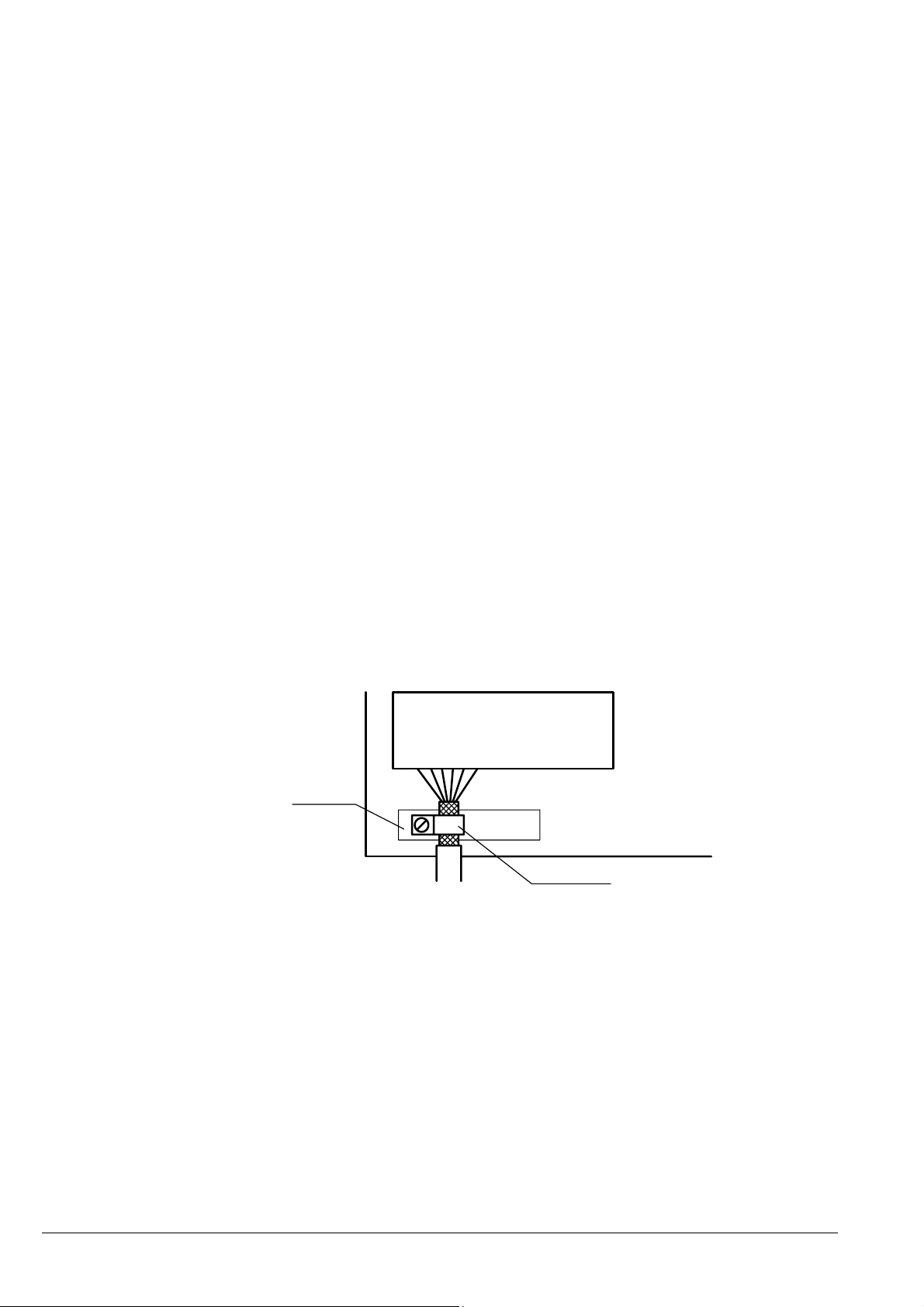
The connection of the cable shielding to the functional ground (PE) must be as
short and low-impedance as possible. It should be made directly to the
mounting plate over a large area with a conductive clip:
control
data line terminals
bare
metal surface
mouting plate
conductive clamp
The cable shielding is to be connected at both cable ends. If equipotential
bonding currents are expected due to the cable arrangement, electrical
isolation is to be performed on one side. In this case, capacitive connection
(approx. 0.1µF/600 V AC) of the shielding on the isolated side must occur.
Disposal Units or unit parts which are no longer needed are to be disposed of in accordance
with the regulations in effect in your country.
6 BAL SX602 ETH EN 3.0
Page 7

Chapter 2 Unit description
Model designation The model designation of the units is:
SX602-xxx/xx/xx-xxx/xx-E0
x = The 'x's in the model designation indicate the size and design of the units (see
Chapter 9).
Unit construction The following figure shows model type SX602-10/10/xx-xxx/xx-xx as example for
the other model types. The front frame of the housing is locked with quick-action
releases and can be hinged downward for opening the unit.
The following figure shows the unit when open and reveals the modular
construction of the units. All components, controls and connections are directly
accessible.
The display modules (LED matrix modules) are found inside the housing front
frame. The control computer and power supply unit are located in the lower
housing section.
Central Processing Unit Power supply unit
Lower housing section
Matrix modules
Housing front frame
Display range The series SX602 includes devices with the following display range:
Character height 160 mm: 4, 6, 8, 10 and 12 characters
Character height 250 mm: 4, 6 and 8 characters
The devices with double-sided display (SX602-xxx/xx/xx-2xx/xx-xx) show the same
information on the front and rear side.
BAL SX602 ETH EN 3.0 7
Page 8

Principle circuit diagram
Central Processing Unit The following figure shows the Central Processing Unit:
Ethernet interface The Ethernet interface is used for activation of the devices. It is a standard-RJ45
socket and has the following specifications:
Data rate: 10/100 Mbps, Automatic detection
Galvanic separation: 1,5 kV
Supported protocols: ICMP, ARP, IP, TCP, UDP, DHCP, Telnet and HTTP
Operation modes: TCP Server, TCP Client and UDP
The units are set-up as TCP server by default. The data
is transmitted to port 8000 via a socket connection.
Configuration: The basic configuration can be set up without external
aids via the menu (see chapter 5). Further settings can
be done via Web Browser or Telnet console (see chapter
4).
The Telnet and HTTP protocols are used exclusively for configuration, not for data
transmission.
8 BAL SX602 ETH EN 3.0
Page 9

Function inputs The function inputs allow, independently of commands via the Ethernet interface, a
reduction the brightness and the flashing of the display (see chapter 4). They are
located on a screw-type terminal strip.
The function inputs are PLC-compatible and are designed for the following signal
voltages:
Signal voltage: L = -3.5...+5 V (open input = L)
H = +18...30 V (active H), M = reference potential
Menu display The parameterization of the devices is carried out in a menu of the menu display.
In normal operation, the following status messages appear in the menu display::
ONNE Data are received at the interface.
DATA The device detects a telegram ending.
No data are received at the interface.
In programming operation, the following status messages appear in the menu
display:
LoAd Static texts are loaded in the text memory.
rEAd Static texts are read from the text memory.
Status indicator The data LED illuminates when data is being received.
Ethernet-LEDs The data transmission rate is detected automatically and displayed via the 100M
and 10M Ethernet LEDs. A permanently lit LED signals a connection having the
indicated speed. Flickering means additional data exchange.
Battery The lithium battery (type CR2032) provides a power reserve for the real-time clock.
It is located in a battery holder, thus making battery replacement easy. The battery
is to be replaced with a new one after three years.
Power supply The power supply of the devices (230 V AC) is connected to the terminals L, N
and PE.
BAL SX602 ETH EN 3.0 9
Page 10

Chapter 3 Character display
LED-matrix The characters are displayed on an LED matrix.
Character sets The character sets Acala 7 and Acala 7 extended are permanently installed in the
units.
Charater set Character display
Acala 7
Acala 7 extended*
AaBbCcDdEeFfGgHhIiJjKkLlMmNnOoPpQqRr
AaBbCcDdEeFfGgHhIi
Proportional font The character sets Acala 7 and Acala 7 extended are represented in non-
proportional font.The same number of pixels is available for the width of each
character.
The character set Acala 7 P, which is preinstalled ex factory and contained on the
data medium, represents the characters in proportional font. Each character uses
the width it requires visually.
PC-Tool The data carrier also contains the PC tool 'Font Manager' for installing the
character sets. In addition to that, the tool is used for creating user-defined
character sets, for saving character sets on data carriers and for restoring the
installed character sets.
LED color The device models SX602-xx/xx/xR-xxx/xx-xx and SX602-xx/xx/xG-xxx/xx-xx have
a display with red and/or green LED color. The LED color cannot be changed
(monochrome display).
The device models SX602-xx/xx/xM-xxx/xx-xx have a display the LED color of
which can be switched between red, green and orange.
10 BAL SX602 ETH EN 3.0
Page 11

t
Chapter 4 Control
Parameterization The units must be parameterized before they can be controlled. Parameterization
occurs in a menu (see Chapter 5).
Ethernet interface ´ The devices are activated via the Ethernet interface (see chapter 2).
Text types The devices can display both dynamic and static texts:
Dynamic texts can be changed while the unit is running. They are generated
from within the process and sent to the display via the Ethernet interface.
Static texts cannot be changed while the unit is running. They are compiled
using the PC tool 'Text Manager' delivered on data carrier and loaded in the
text memory via the Ethernet interface. After that, they can be opened via their
text number.
Automatic line break If the text contains more characters than can be displayed in one line, a line break
is inserted automatically at the end of the line, and the text is continued in the nex
line.
Automatic paging If the text contains more characters than can be displayed in the display, it will be
automatically displayed in paging mode.
Interfacing commands The interfacing of the devices is done using commands according to the following
command table. In the following description of the commands, the numbers in [ ]
refer to the corresponding lines in the command table.
Single commands need a message termination (↵) with the characters CR, LF or
CR/LF.
Command table
Display
dynamic text
Display
fixed text
Entering
variables
Deleting text
Commands for text manipulation
cc...↵
$Tn↵
$VEcc...↵
$VPn↵
$E↵
Transmission of any characters [1]
Calling up Calling up fixed text (n = text number, one to
four digits)
Entering variables from the current insertion position [3]
Selecting insertion position of variables (n = running
number of variables, 0 – 255)
Clearing text in the display [5]
[2]
[4]
BAL SX602 ETH EN 3.0 11
Page 12

Commands for text formatting
Flashing of
individual
Marquee text
Charater set
LED color
Place holder
for variables
Inserting time
Inserting date
Bar graph
$ character
Commands for display options
Flashing
Brightness
Reset
Line break
characters
$C
$F1
$F0
$Y
$M1
$M2
$M3
$M4
$M5
$M6
$A0
$A1
$A2
$VS
$HA
$HH
$HM
$HS
$DA
$DB
$DD
$DM
$DY
$DZ
$DW
$Gnnnn
$$
$F1↵
$↵F0
$B0↵
$B1↵
$B2↵
$0↵
Forced line break [6]
Flashing of following characters on [7]
Flashing of following characters off [8]
Marquee text from current position until end of text or $C [9]
Character set Acala 7 [10]
Character set Acala 7 extended [11]
Not applicable [12]
Not applicable [13]
User-defined character set [14]
Not applicable [15]
Red [16]
Green [17]
Orange [18]
Inserting place holders for variables [19]
Current time(HH:MM:SS) [20]
Hour of current time (HH) [21]
Minute of current time (MM) [22]
Second of current time (SS) [23]
Current date, 4-digit year (TT.MM.JJJJ) [24]
Current date, 2-digit year (TT.MM.JJ) [25]
Current day (TT) [26]
Current month (MM) [27]
Current year, 4-digits (JJJJ) [28]
Current year, 2-digits (JJ) [29]
Weekday in selected dialog language [30]
Bar graph display (nnnn = number of columns) [31]
Display of the '$' character in the text [32]
Flashing of the entire display on [33]
Flashing of the entire display off [34]
Normal [35]
Reduced [36]
Blanking of the display [37]
Restarting the display [38]
12 BAL SX602 ETH EN 3.0
Page 13

Commands for loading and reading back
Time/date
time/date
Time/date
time/date
$SHhhmmss↵
$SDmmddyy↵
$SWx↵
$RH↵
$RD↵
Setting time [39]
Setting date [40]
Weekday (x: 1 = Mo, 2 = Tu, 3 = We etc. until 7 = Su) [41]
Exporting the time via the Ethernet interface [42]
Exporting the day of the week and the date via the
Ethernet interface
[43]
Online texts Dynamic texts are transmitted to the display as data telegrams [1]. Any text found
in the display is cleared when an online text is received.
Static texts Static texts are called up using the command $Tn↵ [2]. n is the text number; it can
be from one to four digits. Any text in the display is cleared when a fixed text is
called up.
Initial text Once the operating voltage has been applied, an LED dot in the upper left-hand
corner of the display illuminates to indicate that the unit is ready for operation. If an
initial text is to appear in the display instead (e.g. 'System operational'), this text is
to be saved in the text memory with text number 0, and displaying of the initial text
is to be set in menu item 20 (see Chapter 5).
Inserting variables This operating mode is used when the units are to display so-called text masks, in
which only certain characters are changed, e.g. for the updating of numerical
values as in the following:
Temp. 172 °C
The text parts Temp. and °C are fixed and do not change. The numbers, on the
other hand, are continually updated variable text components.
In principle, updating could occur with online texts containing both the fixed and the
variable text components. The data transfer required here is considerable,
however.
The SX602 series offers the advantageous alternative of a one-time transmission
of the fixed text components to the display and subsequent insertion of just the
appropriate characters (variables) to update the variable text components. In the
example, the fixed text parts Temp. and °C are displayed by means of the following
data telegram.
$M1Temp. $VS$VS$VS °C$↵
The place holders for variables to be inserted later are marked with $VS [19]. They
first appear blank in the display. A variable corresponds to a character to be
displayed. Up to 256 variables can be inserted into a text.
The place holder from which the variables are to be inserted in the text (insertion
position) is marked with the $VPn↵ command [4]. n is the running number of
variables; it can be from one to three digits (0 – 255). In the example, the first
insertion position is marked with the $VP0↵ command.
Insertion of the variables in the place holders occurs with the $VEcc...↵
command [3]. cc... stands for any characters. In the example, the variables are
inserted with the data telegram $VE172↵.
BAL SX602 ETH EN 3.0 13
Page 14

In the example, the fixed text components were shown in the display as online text.
t
r
Alternatively, they can be prepared as a fixed text called up from the text memory.
The place holders for the variables are also to be marked with $VS in the fixed text.
Deleting text Any text in the display is cleared with the $E↵ command [5]. An LED dot then
illuminates in the upper left-hand corner of the display.
Forced line break If the text contains more characters than can be displayed in one line, a line break
is inserted automatically at the end of the line, and the text is continued in the nex
line. A line break can also be forced at a certain place in the text, for example fo
correct hyphenation [6] using the command $C.
Flashing Including $F1 in the data string causes the following characters to flash [7]. As
soon as $F0 appears in the data string, the following characters are displayed
statically [8].
Flashing of the entire display can be activated with the $F1↵ command [33] and
deactivated with the $F0↵ command [34].
Flashing of the entire display can also be activated with a high signal level at
function input F2. The function input has priority over the commands.
Marquee text Marquee text display is activated from the current position in the text with the $Y
command [9]. It remains active up to the end of the text or a forced line break ($C).
Character set The texts are displayed with the character set specified in menu item 22 as default
(see Chapter 5). For loading another character set, one of the commands $M1,
$M2 or $M5 must be contained in the text [10, 11, 14].
The commands $M1 and $M2 load the permanently installed character sets Acala 7
[10] and Acala 7 extended [11].
A user-defined character set [14] can be loaded with the command $M5.The Acala
7 P character set is preinstalled here. It can be replaced by a character set created
by the user, for example.
The commands $M3 [12], $M4 [13] and $M6 [15] must not be used.
The optional character sets and a tool for generating user-defined character sets
are included on a data medium. The tool is also used to install character sets, to
save character sets to data media and to read back installed character sets.
LED color Devices with switchable LED color (see chapter 3) display the texts in red by
default. For a color change, the command $A0 (red), $A1 (green) or $A2 (orange)
must be contained in the text [16...18].
Inserting time/date The units have a real-time clock with a date and weekday display. The current
time, date or parts of them can be inserted into the text with the $H... and $D...
commands [20 – 30]. The year can be displayed with four [24, 28] or two [25, 29]
digits.
The day of the week is displayed abbreviated to two letters in the language set in
menu item 23 (see Chapter 5).
14 BAL SX602 ETH EN 3.0
Page 15

Bar graph The $Gnnnn command activates the bar graph display [31]. nnnn stands for the
number of illuminating columns, i.e. the length of the bar graph and must always be
four digits.
The illuminating color of the bar graph can only be red or green. The $A2
command for the color orange [18] is ignored in bar graph mode].
$ character The command for displaying the '$' character is $$ [32].
Brightness The brightness of the display can be reduced with the $B1↵ command [36] and
reset to the normal brightness with the $B0↵ command [35].
The brightness can also be reduced with a high signal level on function input F1.
The function input has priority over the control commands.
Blanking Blanking of the display can be activated with the $B2↵ command [37] and
deactivated with the $B0↵ or $B1↵ commands [35, 36]. The text in the display is
not cleared here.
Reset The $0↵ command restarts the unit [38].
Setting time/date Setting of the time occurs with the $SHhhmmss↵ command [39]. hh stands for
hours (24-hour format), mm for minutes and ss for seconds (e.g. $SH204515↵ =
20:45:15 Uhr).
Setting of the date occurs with the $SDddmmyy↵ command [43]. dd stands for the
day, mm for the month and yy for the year (e.g. $SD200804↵ = 20.08.2004).
Setting of the weekday occurs with the $SWx↵ command [41]. x stands for the
respective weekday: 1 = Monday, 2 = Tuesday, 3 = Wednesday, 4 = Thursday, 5
= Friday, 6 = Saturday and 7 = Sunday. The day of the week is displayed
abbreviated to two letters in the language set in menu item 23 (see Chapter 5).
The time, date and weekday can also be set in menu items 90 – 95 (see
Chapter 5).
Reading out time/date The current time can be read out via the interface with the $RH↵ command [45],
and the current date, including the weekday, with the $RD↵ command [46 ].
BAL SX602 ETH EN 3.0 15
Page 16

Chapter 5 Parameterization
Menu display The parameterization of the devices is carried out in a menu of the menu display.
In normal operation, the status messages appear in the menu display (see chapter
2).
Menu operation To reach the menu, press both menu buttons simultaneously (approx. 1 sec.) until
an audible signal is heard and menu item 01 appears in the menu display. Now,
you can navigate in the menu as follows:
Next menu item: Shortly press key [R]
Page menu items forward: Press key [R] long
Previous menu item: Double click on key [R]
Page menu items backward: Double click on [R] and keep it pressed
Next setting Shortly press key [Q]
Page settings forward: Press key [Q] long
Previous setting Double click on key [Q]
Page setting backward: Double click on [Q] and keep it pressed
The menu ends in menu item 99 with the button [R]. The settings made are either
saved (set), not saved (escape) or the factory settings, except for menu item 01,
are reset, depending on the setting selected in menu item 99.
Canceling the menu without saving the settings made is possible by pressing both
menu buttons longer (approx. 1 sec.) or will occur automatically if 60 seconds pass
without a menu button being pressed.
Once the menu is closed, the unit behaves in the same manner as when the
operating voltage was applied.
An LED dot illuminates in the upper left-hand corner of the display in menu mode.
Control of the display is not possible in menu mode.
Menu table The menu items are displayed in the following menu table. The factory settings are
marked with an *. Individual menu items or settings can be suppressed in another
menu item, depending on the unit version or setting.
10 Time-out No time-out *
Time-out after 2 s
Time-out after 4 s
Time-out after 8 s
Time-out after 16 s
Time-out after 32 s
Time-out after 64 s
Time-out after 128 s
20 Initial text Not displaying initial text*
Displaying initial text
21 Paging interval 3 seconds *
L
30 seconds *
Menu item Settings Menu display
L
16 BAL SX602 ETH EN 3.0
Page 17

22 Standard character set Acala 7*
Acala 7 extended
Not applicable
Not applicable
User-defined character set
Not applicable
23 Language German*
French
English
Display test at power-on
IP IP-Address Static*
DHCP
I1 IP-Address 0
Byte 1 (xxx.- . . - -) L 192* L
192.168.127.254* 255
I2 IP-Address 0
Byte 2 (- - -.xxx.- . - -) L 168* L
255
I3 IP-Address 0
Byte 3 (- - -.- - -.xxx.- - -) L 127* L
255
I4 IP-Address 1
Byte 4 (- - -.- . - -.xxx) L 254* L
254
S1 Subnet Mask 0
Byte 1 (xxx.- . . - -) L 255* L
255.255.0.0* 255
S2 Subnet Mask 0
Byte 2 (- - -.xxx.- . - -) L 255* L
255
S3 Subnet Mask 0
Byte 3 (- - -.- - -.xxx.- - -) L 000* L
255
S4 Subnet Mask 1
Byte 4 (- - -.- . - -.xxx) L 000* L
254
Menu item Settings Menu display
E
C
E
U
U
G
F
E
24 Display test No display test at power-on *
P Stat
P DHCP
S
S
S
S
S
S
S
S
BAL SX602 ETH EN 3.0 17
Page 18

G1 Standard-Gateway 0
Byte 1 (xxx.- . . - -) L 192* L
192.168.127.1* 255
G2 Standard-Gateway 0
Byte 2 (- - -.xxx.- . - -) L 168* L
255
G3 Standard-Gateway 0
Byte 3 (- - -.- - -.xxx.- - -) L 127* L
255
G4 Standard-Gateway 1
Byte 4 (- - -.- . - -.xxx) L 001* L
254
90 Setting date (year) 05
L
99
91 Setting date (month) 1
L
12
92 Setting date (day) 1
L
31
93 Setting weekday Monday
Tuesday
Wednesday
Thursday
Friday
Saturday
Sunday
94 Setting time (hours) 0
L
23
95 Setting time (minutes) 0
L
59
99 Saving Saving parameters* (Set)
Not saving parameters (Escape)
Resetting to the default settings (Default)
Menu item Settings Menu display
G
G
G
G
G
G
G
G
L
L
L
L
L
set
ESC
deF
18 BAL SX602 ETH EN 3.0
Page 19

Time-out In menu item 10, it is possible to set whether a time-out occurs, and if so, after
what time. Time-out means that the display is cleared if it has not received a data
telegram after a defined time period. An LED dot then illuminates in the upper lefthand corner of the display.
Initial text Once the operating voltage has been applied, an LED dot in the upper left-hand
corner of the display illuminates to indicate that the unit is ready for operation. If an
initial text is to appear in the display instead (e.g. 'System operational'), this text is
to be stored in the text memory with text number 0, and displaying of the initial text
is to be set in menu item 20.
If a display test is preselected in menu item 24, it appears in the display before the
initial text.
Paging interval If a text contains more characters than can be shown in the display, it is
automatically displayed in paging mode. The page change interval can be set
between 3 and 30 seconds in menu item 21.
Character set In menu item 22, you can set the default character set used to display the texts.
The character sets Acala 7 and Acala 7 extended are permanently installed in the
units.
A user-defined character set can be loaded with the setting U. The Acala 7 P
character set is preinstalled here. It can be replaced by a character set created by
the user, for example.
The settings C, E and U must not be used.
The optional character sets and a tool for generating user-defined character sets
are included on a data medium. The tool is also used to install character sets, to
save character sets to data media and to read back installed character sets.
Language In menu item 23, you can set the language in which the weekday is displayed
(abbreviated to two letters).
Display test In menu item 24, you can set whether a display test is to be performed after the
operating voltage is applied.
Network parameters The network parameters can be set in the menu and no external aids are
necessary. Afterwards the units can be accessed via the network. Further settings
can then be made via the network (see chapter 6).
In the IP menu item, static address assignment or DHCP must be selected.
In the I1...I4 menu items, the four bytes of the IP address are set, if static address
assignment has been selected.
In the G1...G4 menu items, the four bytes of the standard gateway address are set,
if static address assignment has been selected.
In the S1...S4 menu items, the four address bytes of the Subnet Mask are set, if
static address assignment has been selected.
BAL SX602 ETH EN 3.0 19
Page 20

Upon resetting the factory settings (Default) in menu item 99, the following network
parameters are set:
Static address assignment
IP-Address192.168.127.254
Subnet Mask 255.255.000.000
Standard-Gateway 192.168.127.001
Time/date The year, month, day and weekday of the real-time clock are set in menu items
90 – 93. The time at which the clock is to be started is set in menu items 94 – 95.
Then select menu item 99 and select the setting Set there. When the set time is
reached, briefly press the left menu button [↕] the clock is now set to the current
time.
If the settings in menu items 90 – 93 (date) and 94 – 95 (time) are not changed
when the menu is run through, the current settings for the time, date and weekday
are retained when the menu is exited. Therefore, the clock only needs to be set
when running through the menu if this is intended.
Setting the clock can also occur with control commands via the Ethernet interface
(see Chapter 4).
Attention: Setting unrealistic date values, e.g. 31/02/06 can lead to unpredictable
date displays and is therefore impermissible.
20 BAL SX602 ETH EN 3.0
Page 21

Chapter 6 Configuration
MAC address The MAC address of the unit is to be found on the Ethernet coupling of the control
processor (see label). It is possibly needed for commissioning and should be
written down on page 2 of this operating manual before the unit is mounted on a
hardly accessible location.
Basic configuration The basic configuration can be set up without external aids via the menu (see
chapter 5). To integrate the unit in the network, either DHCP must be activated, or
the static IP address, the relevant Subnet Mask and, if necessary, the IP address
of the standard gateway must be set. These values are assigned by the system
administrator and should be known before putting the unit into operation.
Configuration via network As soon as the units can accessed via TCP/IP, additional configuration can take
place via Telnet and HTTP. Access can be password-protected or can be
deactivated, to prevent unauthorized operations. As-delivered and after setting the
default in menu item U, access is enabled.
Additional information The configuration dialogs are self-explanatory. For detailed information, please
refer to the documentation of the Ethernet coupling (Moxa NE4100T type). For
further information and PC tools, please go to www.moxa.com.
Basic setting Via Telnet and HTTP the gateway can inadvertently be parameterized so that it is
no longer accessible via the network. In this case the gateway can be rest in a
defined status via menu and selection of default in menu item U (see chapter 4)
and after resetting of the network parameters it can be accessed via network
again.
Chapter 7 Status messages
Fault messages Serious faults due to improper operation or faulty operating conditions are
indicated in the display. The following messages are possible:
Fault message Cause Elimination
No Text
Syntax Error
The text called up is not saved in the
fixed text memory.
A faulty command was
sent to the display
.
The text is to be loaded into the fixed
text memory.
The command must be corrected
(see command table in chapter
6).
BAL SX602 ETH EN 3.0 21
Page 22

Chapter 8 Character table
0 <NUL> 64 @ 128 € 192 А
1
2 <STX> 66 B 130 é 194 В
3 <ETX> 67 C 131 â 195 Г
4 <EOT> 68 D 132 ä 196 Д
5 ♣ 69 E 133 à 197 Е
6 <ACK> 70 F 134 å 198 Ж
7 <BEL> 71 G 135 ç 199 З
8 <BS> 72 H 136 ê 200 И
9 <HT> 73 I 137 ë 201 Й
10 <LF> 74 J 138 è 202 К
11 ♂ 75 K 139 ï 203 Л
12 ♀ 76 L 140 î 204 М
13 <CR> 77 M 141 ì 205 Н
14 ♫ 78 N 142 ä 206 О
15
16 <DLE> 80 P 144 é 208 Р
17 <XON> 81 Q 145 æ 209 С
18
19 <XOFF> 83 S 147 ô 211 У
20 ¶ 84 T 148 ö 212 Ф
21 <NAK> 85 U 149 ò 213 Х
22 86 V 150 û 214 Ц
23
24
25
26 <EOF> 90 Z 154 ü 218 Ъ
27 <ESC> 91 [ 155 ø 219 Ы
28 92 \ 156 £ 220 Ь
29
30 ▲ 94 ^ 158 × 222 Ю
31 ▼ 95 _ 159 ƒ 223 Я
32 <SPACE> 96 ` 160 á 224
33 ! 97 A 161 í 225 ss
34 " 98 B 162 ó 226
35 # 99 C 163 ú 227
36 $ 100 D 164 ñ 228
37 % 101 E 165 ñ 229
38 & 102 F 166 ª 230
39 ' 103 G 167 o
40 ( 104 H 168 reserved 232
41 ) 105 I 169 233
42 * 106 J 170 234
43 + 107 K 171 235
44 , 108 L 172 236
45 - 109 M 173 237
46 . 110 N 174 238
47 / 111 O 175 239
48 0 112 P 176 240
49 1 113 Q 177 241
50 2 114 R 178 242
51 3 115 S 179 reserved 243
52 4 116 T 180 reserved 244 reserved
53 5 117 U 181 reserved 245 reserved
54 6 118 V 182 reserved 246
55 7 119 W 183 reserved 247
56 8 120 X 184 reserved 248
57 9 121 Y 185 reserved 249
58 : 122 Z 186 reserved 250
59 ; 123 { 187 Pt 251
60 < 124 | 188 252
61 = 125 } 189 ¢ 253
62 > 126 ~ 190 ¥ 254
63 ? 127 ⌂ 191 ë 255
☺
b
b
↑
↓
↔
65 A 129 ü 193 Б
79 O 143 å 207 П
82 R 146 æ 210 Т
87 W 151 ù 215 Ч
88 X 152 ÿ 216 Ш
89 Y 153 ö 217 Щ
93 ] 157 ø 221 Э
231
ρ
22 BAL SX602 ETH EN 3.0
Page 23

Chapter 9 Technical data
Unit properties The model designation is structured as follows:
SX602 – / / – / – E 0
: : : : : : : : : : :
4 characters 0 4 : : : : : : : : :
6 characters 0 6 : : : : : : : : :
8 characters 0 8 : : : : : : : : :
10 characters 1 0 : : : : : : : : :
12 characters 1 2 : : : : : : : : :
20 characters 2 0 : : : : : : : : :
40 characters 4 0 : : : : : : : : :
: : : : : : : : :
Character height of 50 mm 0 5 : : : : : : :
Character height of 100 mm 1 0 : : : : : : :
Character height of 160 mm 1 6 : : : : : : :
Character height of 250 mm 2 5 : : : : : : :
: : : : : : :
Standard LED 0 : : : : : :
LED for outdoor use 2 : : : : : :
: : : : : :
Red character color R : : : : :
Green character color G : : : : :
Switchable red/green/orange character color M : : : : :
: : : : :
Display readable on one side 1 : : : :
Display readable on both sides 2 : : : :
: : : :
Steel sheet housing, coated 0 : : :
Steel sheet housing, bilayer painting 1 : : :
Steel sheet housing V2A, coated 2 : : :
Steel sheet housing V2A, brushed 3 : : :
Steel sheet housing V4A, brushed 4 : : :
: : :
Protection type IP54 0 : :
Protection type IP65 1 : :
Protection type IP54 climate adjustment 2 : :
Protection type IP54 climate adjustment and heating 4 : :
: :
Wall mounting, cable entry point from the bottom 0 :
Wall mounting, cable entry point from the top 1 :
Hanging installation, cable entry point from the bottom 2 :
Hanging installation, cable entry point from the top 3 :
Wall and hanging installation, cable entry point from the bottom 4 :
Wall and hanging installation, cable entry point from the top 5 :
:
Power supply 230 V AC ±15 %, 50 Hz A
Power supply 115 V AC ±15 %, 60 Hz C
Housing colors Front pane: RAL 7035 light grey
RAL 5002 ultramarine
Front frame SX602-xxx/xx/xR-xxx/xx-xx: plastic, tinted red, non-reflective
SX602-xxx/xx/xM-xxx/xx-xx: plastic, clear, non-reflective
Ambient conditions Operating temperature: 0…40 °C
Storage temperature: -30…85 °C
Relative humidity: max. 95 % (non-condensing)
BAL SX602 ETH EN 3.0 23
Page 24

Max. power consumption Units with character height of 50 mm
One-sided display Double-sided display
SX602-20/05/0R-1xx/xx-xx approx. 45 VA SX602-20/05/0R-2xx/xx-xx approx. 85 VA
SX602-20/05/0M-1xx/xx-xx approx. 85 VA SX602-20/05/0M-2xx/xx-xx approx. 165 VA
SX602-40/05/0R-1xx/xx-xx approx. 75 VA SX602-40/05/0R-2xx/xx-xx approx. 170 VA
SX602-40/05/0M-1xx/xx-xx approx. 130 VA SX602-40/05/0M-2xx/xx-xx approx. 320 VA
Units with character height of 100 mm
One-sided display Double-sided display
SX602-10/10/0R-1xx/xx-xx approx. 40 VA SX602-10/10/0R-2xx/xx-xx approx. 75 VA
SX602-10/10/0G-1xx/xx-xx approx. 40 VA SX602-10/10/0G-2xx/xx-xx approx. 75 VA
SX602-20/10/0R-1xx/xx-xx approx. 75 VA SX602-20/10/0R-2xx/xx-xx approx. 150 VA
SX602-20/10/0G-1xx/xx-xx approx. 75 VA SX602-20/10/0G-2xx/xx-xx approx. 150 VA
Units with character height of 160 mm
One-sided display Double-sided display
SX602-04/16/0R-1xx/xx-xx approx. 45 VA SX602-04/16/0R-2xx/xx-xx approx. 80 VA
SX602-04/16/0G-1xx/xx-xx approx. 45 VA SX602-04/16/0G-2xx/xx-xx approx. 80 VA
SX602-06/16/0R-1xx/xx-xx approx. 60 VA SX602-06/16/0R-2xx/xx-xx approx. 115 VA
SX602-06/16/0G-1xx/xx-xx approx. 60 VA SX602-06/16/0G-2xx/xx-xx approx. 115 VA
SX602-08/16/0R-1xx/xx-xx approx. 80 VA SX602-08/16/0R-2xx/xx-xx approx. 150 VA
SX602-08/16/0G-1xx/xx-xx approx. 80 VA SX602-08/16/0G-2xx/xx-xx approx. 150 VA
SX602-10/16/0R-1xx/xx-xx approx. 95 VA SX602-10/16/0R-2xx/xx-xx approx. 180 VA
SX602-10/16/0G-1xx/xx-xx approx. 95 VA SX602-10/16/0G-2xx/xx-xx approx. 180 VA
SX602-12/16/0R-1xx/xx-xx approx. 110 VA SX602-12/16/0R-2xx/xx-xx approx. 215 VA
SX602-12/16/0G-1xx/xx-xx approx. 110 VA SX602-12/16/0G-2xx/xx-xx approx. 215 VA
Units with character height of 250 mm
One-sided display Double-sided display
SX602-04/25/0R-1xx/xx-xx approx. 90 VA SX602-04/25/0R-2xx/xx-xx approx. 170 VA
SX602-04/25/0M-1xx/xx-xx approx. 140 VA SX602-04/25/0M-2xx/xx-xx approx. 270 VA
SX602-06/25/0R-1xx/xx-xx approx. 135 VA SX602-06/25/0R-2xx/xx-xx approx. 260 VA
SX602-06/25/0M-1xx/xx-xx approx. 205 VA SX602-06/25/0M-2xx/xx-xx approx. 400 VA
SX602-08/25/0R-1xx/xx-xx approx. 180 VA SX602-08/25/0R-2xx/xx-xx approx. 350 VA
SX602-08/25/0M-1xx/xx-xx approx. 270 VA SX602-08/25/0M-2xx/xx-xx approx. 530 VA
The power consumption of the device versions SX602-xx/xx/0R-xxx/xx-xx also
applies for the following device versions:
SX602-xx/xx/0G-xxx/xx-xx LED green
SX602-xx/xx/2x-xxx/xx-xx LEDs for outdoor application
For units with built-in heating, the values for power consumption specified in the
table increase by approx. 10 – 200 VA (exact values on request), depending on the
unit size).
Fixed text memory Capacity: 128 KBytes
Number of texts: max. 10.000
Length of texts: max. 2048 characters
Real-time clock Precision: 20 ppm
24 BAL SX602 ETH EN 3.0
Page 25

Chapter 10 Unit measurements and weights
Units with one-side display
and character height of
The following figure shows unit version SX602-20/05/0x-1xx/xx-xx, representing
the other unit versions listed in the following table. All dimensions are in mm.
50 and 100 mm
Unit version a Weight
SX602-20/05/0x-1xx/xx-xx 1040 approx. 16 kg
SX602-40/05/0x-1xx/xx-xx 1960 approx. 27 kg
SX602-10/10/0x-1xx/xx-xx 1040 approx. 16 kg
SX602-20/10/0x-1xx/xx-xx 1960 approx. 27 kg
Units with double-sided
display and character height
The following figure shows unit version SX602-20/05/0x-2xx/xx-xx, representing
the other unit versions listed in the following table. All dimensions are in mm.
of 50 and 100 mm
Unit version a Weight
SX602-20/05/0x-2xx/xx-xx 1040 approx. 16 kg
SX602-40/05/0x-2xx/xx-xx 1960 approx. 27 kg
SX602-10/10/0x-2xx/xx-xx 1040 approx. 16 kg
SX602-20/10/0x-2xx/xx-xx 1960 approx. 27 kg
BAL SX602 ETH EN 3.0 25
Page 26

Units with one-side display
and character height of
100 and 250 mm
The following figure shows unit version SX602-06/16/0x-1xx/xx-xx, representing
the other unit versions listed in the following table. All dimensions are in mm.
Unit version a b Weight
SX602-04/16/0x-1xx/xx-xx 670 300 approx. 13 kg
SX602-06/16/0x-1xx/xx-xx 960 300 approx. 18 kg
SX602-08/16/0x-1xx/xx-xx 1240 300 approx. 22 kg
SX602-10/16/0x-1xx/xx-xx 1520 300 approx. 26 kg
SX602-12/16/0x-1xx/xx-xx 1810 300 approx. 30 kg
SX602-04/25/0x-1xx/xx-xx 1030 400 approx. 23 kg
SX602-06/25/0x-1xx/xx-xx 1500 400 approx. 32 kg
SX602-08/25/0x-1xx/xx-xx 1960 400 approx. 40 kg
26 BAL SX602 ETH EN 3.0
Page 27

Units with double-sided
display and character height
of 100 and 250 mm
The following figure shows unit version SX602-06/16/0x-2xx/xx-xx, representing
the other unit versions listed in the following table. All dimensions are in mm.
Unit version a b Weight
SX602-04/16/0x-2xx/xx-xx 670 300 approx. 22 kg
SX602-06/16/0x-2xx/xx-xx 960 300 approx. 28 kg
SX602-08/16/0x-2xx/xx-xx 1240 300 approx. 34 kg
SX602-10/16/0x-2xx/xx-xx 1520 300 approx. 40 kg
SX602-12/16/0x-2xx/xx-xx 1810 300 approx. 46 kg
SX602-04/25/0x-2xx/xx-xx 1030 400 approx. 36 kg
SX602-06/25/0x-2xx/xx-xx 1500 400 approx. 48 kg
SX602-08/25/0x-2xx/xx-xx 1960 400 approx. 60 kg
BAL SX602 ETH EN 3.0 27
Page 28

28 BAL SX602 ETH EN 3.0
 Loading...