

Page 1

Pos: 2 /Siebert/Bedienungsanleitungen/S erie SX502 / SX602/Titelseiten/SX602 PFN RT @ 3\mod_1465903296097_48.d ocx @ 25854 @ @ 1
Series SX602
Alphanumeric large size displays
with Profinet IO RT interface
Operating instructions
Pos: 3 /Siebert/Seitenumbruch @ 0\m od_1314194553878_0.docx @ 150 @ @ 1
Page 2

Pos: 4 /Siebert/Bedienungsanleitungen/G erätebeschreibung Grossanzeigen alle Serie n/Kontakt @ 1\mod_133966895154 0_48.docx @ 4323 @ 1 @ 1
1 Contact
www.siebert-group.com
GERMANY
Siebert Industrieelektronik GmbH
Siebertstrasse, D-66571 Eppelborn
P.O. Box 11 30, D-66565 Eppelborn
Phone +49 (0)6806 980-0, Fax +49 (0)6806 980-999
email: info.de@siebert-group.com
AUSTRIA
Siebert Österreich GmbH
Mooslackengasse 17. A-1190 Wien
Phone +43 (0)1 890 63 86-0, Fax +43 (0)14 890 63 86-99
email: info.at@siebert-group.com
FRANCE
Siebert France Sarl
4 rue de l’Abbé Louis Verdet, F-57200 Sarreguemines
P.O. Box 90 334, F-57203 Sarreguemines Cédex
Phone +33 (0)3 87 98 63 68, Fax +33 (0)3 87 98 63 94
email: info.fr@siebert-group.com
ITALY
Siebert Italia Srl
Via Galileo Galilei 2A, I-39100 Bolzano (BZ)
Phone +39 (0)471 053753 Fax +39 (0)471 053754
email info.it@siebert-group.com
THE NETHERLANDS
Siebert Nederland B.V.
Jadedreef 26, NL-7828 BH Emmen
Phone +31 (0)591-633444, Fax +31 (0)591-633125
email: info.nl@siebert-group.com
SWITZERALND
Siebert AG
Bützbergstrasse 2, P.O. Box 91, CH-4912 Aarwangen
Phone +41 (0)62 922 18 70, Fax +41 (0)62 922 33 37
email: info.ch@siebert-group.com
Pos: 5 /Siebert/Seitenumbruch @ 0\m od_1314194553878_0.docx @ 150 @ @ 1
BAL SX602 PFN RT 2/36
Page 3

Pos: 6 /Siebert/Bedienungsanleitungen/G erätebeschreibung Grossanzeigen alle Serie n/Rechtlicher Hinweis @ 1\mod_1 339668878995_48.docx @ 4317 @ 1 @ 1
2 Legal note
© Siebert Industrieelektronik GmbH
This operation manual has been prepared with the utmost care. However, we do not accept any
liability for possible errors. We always appreciate your suggestions for improvement, corrections,
comments and proposals. Please contact us: editing@siebert-group.com
Siebert®, LRD® and XC-Board® are registered trademarks of Siebert Industrieelektronik GmbH. All
other product names mentioned herein may be trademarks or registered trademarks of their respective
owners.
We reserve the right to make alterations to the technical data and delivery options without notice. - All
rights reserved, including the rights of translation. No part of this document may in any form or by any
means (print, photocopy, microfilm or any other process) be reproduced or by using electronic
systems be processed, copied or distributed without our written permission.
Pos: 7 /Siebert/Seitenumbruch @ 0\m od_1314194553878_0.docx @ 150 @ @ 1
BAL SX602 PFN RT 3/36
Page 4

Pos: 8 /Siebert/Bedienungsanleitungen/M odul Inhaltsverzeichnis @ 1\mod_1352 981287156_48.docx @ 5155 @ @ 1
Table of contents
1 Contact 2
2 Legal note 3
3 Safety precautions 7
Important information ......................................................................................................................................... 7
Safety ................................................................................................................................................................. 7
Intended use ....................................................................................................................................................... 7
Mounting and installation .................................................................................................................................... 7
Grounding ........................................................................................................................................................... 8
EMC measures ................................................................................................................................................... 8
Disposal .............................................................................................................................................................. 8
4 Unit description 9
Model designation .............................................................................................................................................. 9
Unit construction ................................................................................................................................................. 9
Principle circuit diagram ................................................................................................................................... 10
Central Processing Unit .................................................................................................................................... 11
Profinet-IO interface ......................................................................................................................................... 11
Serial Interface ................................................................................................................................................. 11
Function inputs ................................................................................................................................................. 12
Menu display .................................................................................................................................................... 12
Status indicators ............................................................................................................................................... 12
Battery .............................................................................................................................................................. 13
Power supply .................................................................................................................................................... 13
5 Character display 14
LED matrix ........................................................................................................................................................ 14
Character sets .................................................................................................................................................. 14
Proportional lettering ........................................................................................................................................ 14
LED color .......................................................................................................................................................... 14
6 Configuration 15
MAC address .................................................................................................................................................... 15
GSDML data file ............................................................................................................................................... 15
Configuration .................................................................................................................................................... 15
7 Text types 16
8 Operating mode 'Quick call of static texts' 17
Operating mode ................................................................................................................................................ 17
Input-/Output data bytes ................................................................................................................................... 17
Configuration inside IO controller ..................................................................................................................... 17
Data format ....................................................................................................................................................... 17
BAL SX602 PFN RT 4/36
Page 5

9 Operating mode 'Dynamic and static texts' 18
Operating mode ................................................................................................................................................ 18
Output data bytes ............................................................................................................................................. 18
Configuration inside IO controller ..................................................................................................................... 18
Example of configuration .................................................................................................................................. 18
Data transmission ............................................................................................................................................. 18
Block diagram of the handshake method ......................................................................................................... 18
Data segmentation ........................................................................................................................................... 19
Functional building block .................................................................................................................................. 19
Text types ......................................................................................................................................................... 19
Commands ....................................................................................................................................................... 19
Table of commands .......................................................................................................................................... 19
Display dynamic text ........................................................................................................................................ 21
Static texts ........................................................................................................................................................ 21
Inserting variables ............................................................................................................................................ 21
Deleting text ...................................................................................................................................................... 21
Flashing ............................................................................................................................................................ 21
Marquee text ..................................................................................................................................................... 22
Forced line break .............................................................................................................................................. 22
Character set .................................................................................................................................................... 22
LED color .......................................................................................................................................................... 22
Inserting time/date ............................................................................................................................................ 22
Bar graph .......................................................................................................................................................... 22
Character $ ....................................................................................................................................................... 22
Brightness ......................................................................................................................................................... 23
Brightness ......................................................................................................................................................... 23
Reset ................................................................................................................................................................ 23
Setting time/date............................................................................................................................................... 23
Reading out time/date ...................................................................................................................................... 23
Paging .............................................................................................................................................................. 23
Initial text .......................................................................................................................................................... 23
10 Parameterization 24
Menu ................................................................................................................................................................. 24
Menu operation................................................................................................................................................. 24
Menu table ........................................................................................................................................................ 24
Operation mode ................................................................................................................................................ 25
Output data bytes ............................................................................................................................................. 25
Time-out ........................................................................................................................................................... 26
Initial text .......................................................................................................................................................... 26
BAL SX602 PFN RT 5/36
Page 6

Paging .............................................................................................................................................................. 26
Character set .................................................................................................................................................... 26
Language .......................................................................................................................................................... 26
Display test ....................................................................................................................................................... 26
Set time/date .................................................................................................................................................... 26
11 Status messages 27
Fault messages ................................................................................................................................................ 27
12 Character table 28
13 Technical data 29
Unit properties .................................................................................................................................................. 29
Housing colors .................................................................................................................................................. 29
Front frame ....................................................................................................................................................... 29
Ambient conditions ........................................................................................................................................... 30
Max. power consumption ................................................................................................................................. 30
Screw-type terminals ........................................................................................................................................ 30
Fixed text memory ............................................................................................................................................ 30
Marquee ........................................................................................................................................................... 30
Real-time clock ................................................................................................................................................. 30
Dimensions and weights .................................................................................................................................. 31
=== Ende der Liste für Textmarke Inhalt 1 ===
Pos: 10 /Siebert/Seitenumbruch @ 0\ mod_1314194553878_0.docx @ 150 @ @ 1
BAL SX602 PFN RT 6/36
Page 7
Bus errors may result in personal injury or material damage. Therefore it must be noted that
the reset of the display with command $0 and activation of the menu may cause a bus error.
Information intended to help you to avoid death, bodily harm or considerable damage to
property is highlighted by the warning triangle shown here; it is imperative that this
information be properly heeded.
Components inside the units are energized with electricity during operation. For this reason,
mounting and maintenance work may only be performed by professionally-trained personnel
while observing the corresponding safety regulations.
The user must ensure that the attachment hardware, the unit carrier and the anchoring at the
unit carrier are sufficient to securely support the unit under the given surrounding conditions.
When the housing fasteners are opened, the front frame of the housing hinges out upward or
downward (depending on the unit version) automatically.
Pos: 11 /Siebert/Bedienungsanleitungen/ Gerätebeschreibung Grossanzeigen alle Serien/Sicherheitshinweise Grossanzeige n SX502 Busfehler @ 1\mod_13857 23478553_48.docx @ 7030 @ 1222222 2 @ 1
3 Safety precautions
Important information
Read these operating instructions before starting the unit. They provide you with important information
on the use, safety and maintenance of the units. This helps you to protect yourself and prevent
damage to the unit.
The operating instructions are intended for trained professional electricians familiar with the safety
standards of electrical technology and industrial electronics.
Store these operating instructions in an appropriate place.
The manufacturer is not liable if the information in these operating instructions is not complied with.
Safety
The repair and replacement of components and modules may only be carried out by the manufacturer
for safety reasons and due to the required compliance with the documented unit properties.
The units do not have a power switch. They are operative as soon as the operating voltage is applied.
Intended use
The units are intended for use in industrial environments. They may only be operated within the limit
values stipulated by the technical data.
When configuring, installing, maintaining and testing the units, the safety and accident-prevention
regulations relevant to use in each individual case must be complied with.
Trouble-free, safe operation of the units requires proper transport, storage, installation, mounting and
careful operation and maintenance of the units.
Mounting and installation
The attachment options for the units were conceived in such a way as to ensure safe, reliable
mounting.
The units are to be mounted in such a way that they can be opened up while mounted. Sufficient
space for the cables must be available in the unit near the cable entries.
Sufficient space is to be kept clear around the units to ensure air circulation and to prevent the buildup of heat resulting from use. The relevant information must be heeded in the case of units ventilated
by other means.
BAL SX602 PFN RT 7/36
Page 8

① mounting plate
② conductive clamp
③ data lines
④ cable shielding
Grounding
All devices are equipped with a metal housing. They comply with safety class I and require a
protective earth connection. The connecting cable for the operating voltage must contain a protective
earth wire of a sufficient cross section (DIN VDE 0106 part 1, DIN VDE 0411 part 1).
EMC measures
The devices comply with the current EU Directive (EMC Directive) and provide the required
interference immunity. Observe the following when connecting the operating voltage and data cables:
Use shielded data cables.
The data and operating voltage cables must be laid separately. They may not be laid together with
heavy-current cables or other interference-producing cables.
The cable thickness must be properly assessed (DIN VDE 0100 Part 540).
The cable lengths inside the units are to be kept as short as possible to prevent interference. This
applies especially to unshielded operating voltage cables. Shielded cables are also to be kept short
due to any interference which might be emitted by the shielding.
Neither excessively long cables nor cable loops may be placed inside the units.
The connection of the cable shielding to the functional ground (PE) must be as short and low-
impedance as possible. It should be made directly to the mounting plate over a large area with a
conductive clip:
The cable shielding is to be connected at both cable ends. If equipotential bonding currents are
expected due to the cable arrangement, electrical isolation is to be performed on one side. In this
case, capacitive connection (approx. 0.1μF/600 V AC) of the shielding on the isolated side must occur.
Disposal
Units or unit parts which are no longer needed are to be disposed of in accordance with the
regulations in effect in your country.
Pos: 12 /Siebert/Seitenumbruch @ 0\ mod_1314194553878_0.docx @ 150 @ @ 1
BAL SX602 PFN RT 8/36
Page 9

Central Processing Unit
Power supply unit
Connector plug for power supply
Matrix modules
Lower housing section
Housing front frame
Pos: 13 /Siebert/Bedienungsanleitungen/ Serie SX502 / SX602/Gerätebeschreibung/Ü BS Gerätebeschreibung @ 0\mod _1317299752517_48.docx @ 2907 @ 1 @ 1
4 Unit description
Pos: 14 /Siebert/Bedienungsanleitunge n/Serie SX502 / SX602/Gerätebeschreibung/G eltungsbereich/SX602 Geltungsbereic h PFN RT @ 3\mod_146590358217 3_48.docx @ 25860 @ 2 @ 1
Model designation
This manual applies to units with the following model designation (x = the 'x's in the model designation
indicate the size and design of the units see Chapter 14):
Pos: 15 /Siebert/Bedienungsanleitungen/ Serie SX502 / SX602/Gerätebeschreibung/G eräteaufbau/SX602 Geräteaufbau PFN RT @ 3\mod_1465903805669_48.d ocx @ 25867 @ 2 @ 1
Unit construction
The following figure shows model type SX602-10/10/xx-xxx/xx-xx as example for the other model
types. The front frame of the housing is locked with quick-action releases. When opening the unit the
front frame hinges downward.
The following figure shows the unit when open.
SX602-xxx/xx/xx-xxx/xx-YP
Pos: 16 /Siebert/Bedienungsanleitungen/ Serie SX502 / SX602/Gerätebeschreibung/ Prinzipschaltbild/Prinzipschaltbild neu/Pri nzipschaltbild SX502 PFN RT, SX 602 PFN RT @ 2\mod_1408012971720_ 48.docx @ 9128 @ 2 @ 1
Units with double-sided display show the same information on the front and on the rear side.
BAL SX602 PFN RT 9/36
Page 10
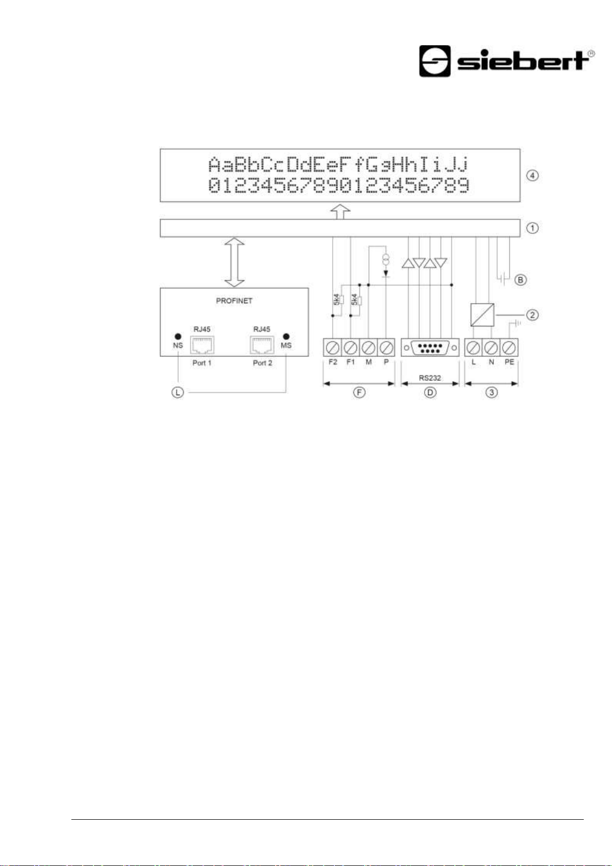
① Central Processing Unit
② Power supply unit
③ Power supply
④ Display
Ⓑ Battery
Ⓓ Sub D connector – serial interface
Ⓕ Function input
Ⓛ Status indicato
Principle circuit diagram
BAL SX602 PFN RT 10/36
Page 11
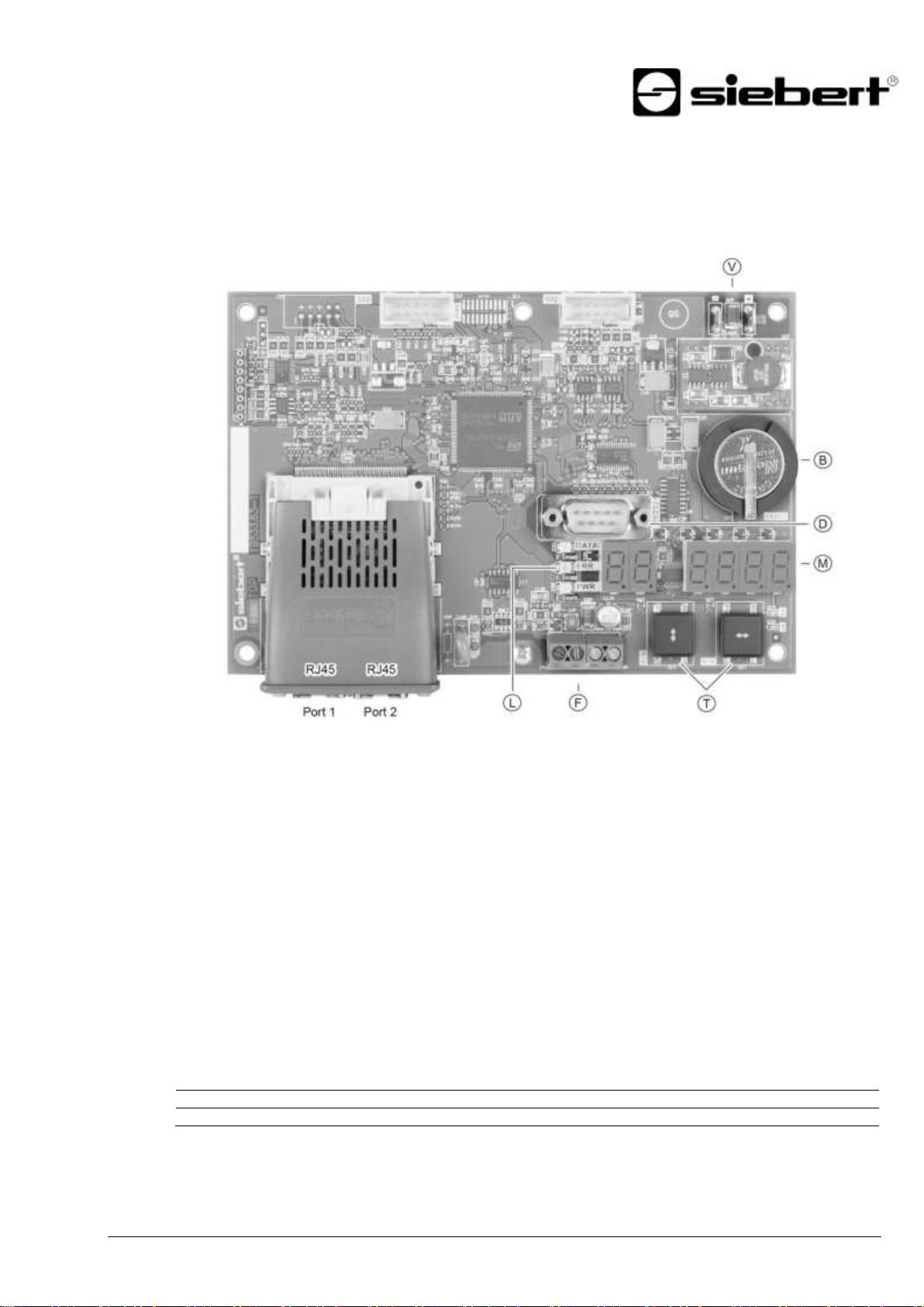
Ⓑ Battery
Ⓓ Sub D connector – Serial interface
Ⓕ Function input
Ⓛ Status indicators
Ⓜ Menu display
Ⓣ Menu button
Ⓥ Power supply
Pin 1 2 3 4 5 6 7 8
9
Signal
–
RxD
TxD – COM
–
RTS
CTS
–
Pos: 17 /Siebert/Bedienungsanleitungen/ Serie SX502 / SX602/Gerätebeschreibu ng/Steuerrechner/Steuerrechner aktuell/Ste uerrechner SX502 ETH/IP, MDB TCP, PFN RT, SX602 PFN RT @ 2\mod_14 08353413797_48.docx @ 9448 @ 2 @ 1
Central Processing Unit
The following figure shows the Central Processing Unit, located in the lower part of the housing.
Pos: 18 /Siebert/Bedienungsanleitungen/ Serie SX502 / SX602/Gerätebeschreibu ng/Schnittstellen/Profinet/Profinet-IO- Schnittstelle S302/SX302 PFN IRT, SX5 02 PFN RT, SX602 PFN RT @ 3\mod_1 443085005617_48.docx @ 19565 @ 2 @ 1
Profinet-IO interface
The Profinet-IO interface is located on the RJ45 socket of the Profinet-IO coupling.
The units have an Ethernet switch with 2 ports. Connection can be made via Port1 or Port2.
The GSDML data file is included on disk in delivery.
Pos: 19 /Siebert/Bedienungsanleitungen/ Serie SX502 / SX602/Gerätebeschreibung/ Schnittstellen/Seriell/Serielle Schnittst elle SX502 ETH/IP, IBSPDGWY,MDBTC P,MDBTCPGWY,DVN,PFB,PFN RT, SX 602 PFN RT @ 2\mod_14080190695 37_48.docx @ 9211 @ 2 @ 1
Serial Interface
The interface RS232 is determined for programming the device using a PC, for example for loading
static texts in the text memory and for installing character sets by means of the PC tools
'DisplayManager' and 'FontManager' provided on data carrier.
The interface RS232 is located, on the sub D connector of the control computer. It has the following
assignment:
The PC connection is established using a standard null-modem cable.
The parameters of the interface are as follows: 9600 bauds, 8 data bits, no parity, 1 stop bit, RTS/CTS
handshake, CR/LF protocol, no addressing.
Pos: 20 /Siebert/Bedienungsanleitungen/ Serie S302/SX302 SX502 SX602 Überei nstimmungen/Gerätebeschreibung Grossa nzeigen Übereinstimmung versch. S erien/Gerätebeschreibung S302/SX302 SX 502 SX602/Funktionseingänge/Fun ktionseingänge S302/SX302 PFN IRT, S X502 PFN RT, SX602 PFN RT Einleitungss atz @ 2\mod_1395322132214_4 8.docx @ 7789 @ 2 @ 1
BAL SX602 PFN RT 11/36
Page 12

Function inputs
The function inputs are located on the screw-type terminal strip of the control computer. They allow
reduction in brightness and flashing of the display, independently of commands via the PROFINET IO
interface (see Chapter 9).
Pos: 21 /Siebert/Bedienungsanleitungen/ Serie S302/SX302 SX502 SX602 Überei nstimmungen/Gerätebeschreibung Grossa nzeigen Übereinstimmung versch. S erien/Gerätebeschreibung S302/SX302 SX 502 SX602/Funktionseingänge/Fun ktionseing.S302ANA,CAN,DVN,ETH,IBS,MD B,MDBTCP,NTP,PFN,PFNIRT,SER ,TMR,WTH,WTS,SX502/SX302/SX60 2 su @ 2\mod_1395322124370_48.doc x @ 7771 @ @ 1
The function inputs are designed for the following signal voltages:
Signal voltage: L = -3.5...+5 V (open input = L)
H = +18...30 V (active H), M = reference potential
Pos: 22 /Siebert/Bedienungsanleitungen/ Serie SX502 / SX602/Gerätebeschreibung/M enüanzeige/Menüanzeige neu/SX602 M enüanzeige PFN RT @ 3\mod_1465 905792966_48.docx @ 25916 @ 2 @ 1
Menu display
The parameterization of the units is carried out in a menu of the menu display:
In normal operation, the following status messages can appear in the menu display:
The display is waiting for new data
Data are received at the interface
The unit detects a telegram ending
In the operation mode 'Quick call of static texts' the currently valid command is shown as hexadecimal
number.
During the start-up on Profinet the following status messages may appear on the menu display:
The display was not assigned with a name yet
The display was not assigned with an IP address yet
Display is ready for Profinet
In programming mode the following status messages can appear on the menu display:
Static texts are loaded in the text memory
Static texts are read out from the text memory
During the start-up or in case of error further messages, which are of internal nature, appear.
Pos: 23 /Siebert/Bedienungsanleitungen/ Serie S302/SX302 SX502 SX602 Überei nstimmungen/Gerätebeschreibung Grossa nzeigen Übereinstimmung versch. S erien/Gerätebeschreibung S302/SX302 SX 502 SX602/Statusanzeigen neu/Statusan zeigen SX502 PFN RT SX602 PFN R T @ 2\mod_1408018530096_48.docx @ 9183 @ 2 @ 1
Status indicators
The status indicators (LEDs) of the control computer and the Profinet coupling have the following
meaning:
LEDs Ⓛ see fig. control computer:
DATA Data transmission in progress
ERR False command
PWR Internal meaning
LED NS: on the left, next to the RJ45 socket of port 1:
Off Offline No connection to the IO controller
Green Online (RUN) Connection to the IO controller
IO controller in RUN state
Green, flashing Online (STOP) Connection to the IO controller
IO controller in STOP state
LED MS: on the right, next to the RJ45 socket of port 2:
Off Not initialized No connection
Module in ˈSETUPˡ or ˈNW INITˈ state
Green Normal operation Module has shifted from the ˈNW INITˈ state
Green, 1 flash Diagnostic events Diagnostic events present
Green, 1 Hz DCP Flash Used by engineering tools to identify the node on the
network
BAL SX602 PFN RT 12/36
Page 13

Red Exception error Module in state ˈEXCEPTIONˈ
Red, 1 flash Configuration error Expected identification differs from real identification
Red 2 flashes IP address error IP address not set
Red, 3 flashes Station name error Station name not set
Red, 4 flashes Internal error Module has encountered a major internal error
Pos: 24 /Siebert/Bedienungsanleitunge n/Serie S302/SX302 SX502 SX602 Überei nstimmungen/Gerätebeschreibung Grossa nzeigen Übereinstimmung versch. Serie n/Gerätebeschreibung S302/SX302 SX 502 SX602/Batterie/Batterie S302 DCF, SX502 DVN, ETH, ETH/IP,MDB, IBSPDGW Y, MDBTCP,MDBTCPGWY, PFB, PFN IRT, s.u. @ 2\mod_14083564234 44_48.docx @ 9487 @ 2 @ 1
Battery
The lithium battery (type CR2032) provides a power reserve for the real-time clock. It is located in a
battery holder and should be replaced after three years.
Pos: 25 /Siebert/Bedienungsanleitunge n/Gerätebeschreibung Grossanzeigen alle Serien/Betriebsspannung Grossanzeige n @ 0\mod_1315494019425_48.docx @ 1864 @ 2 @ 1
Power supply
The screw-type terminals for the power supply are located on the power supply unit in the bottom
section of the housing. They have the following designations:
Devices for a power supply 115 V AC or 230 V AC L, N and PE
Devices for a power supply 24 V DC +, – and PE
Pos: 26 /Siebert/Seitenumbruch @ 0\ mod_1314194553878_0.docx @ 150 @ @ 1
BAL SX602 PFN RT 13/36
Page 14

Character set
Character display
Acala 7
AaBbCcDdEeFfGgHhIiJjKkLlMmNnOoPpQqRr
Acala 7 extended*
AaBbCcDdEeFfGgHhIi
Pos: 27 /Siebert/Bedienungsanleitunge n/Serie SX502 / SX602/Zeichendarstellung/ÜB S Zeichendarstellung @ 0\mod_13 17306112128_48.docx @ 2977 @ 1 @ 1
5 Character display
Pos: 28 /Siebert/Bedienungsanleitungen/ Serie SX502 / SX602/Zeichendarstellung/S X602 LED-Matrix PFN RT @ 3\ mod_1465908413330_48.docx @ 25933 @ 2 @ 1
LED matrix
Pos: 29 /Siebert/Bedienungsanleitungen/ Serie SX502 / SX602/Zeichendarstellung/S X602 Zeichensätze PFN RT @ 3\m od_1465908639121_48.docx @ 25947 @ 2 @ 1
Character sets
The character sets Acala 7 and Acala 7 extended are permanently installed in the devices.
The characters are displayed on an LED matrix.
Pos: 30 /Siebert/Bedienungsanleitunge n/Serie SX502 / SX602/Zeichendarstellung/S X602 Proportionalschrift PFN RT @ 3\ mod_1465908678786_48.docx @ 259 54 @ 2 @ 1
Proportional lettering
The character sets Acala 7 and Acala 7 extended display the characters in non-proportional lettering
(monospace font). The same number of pixels is available for the width of each character.
Character set Acala 7 P, which displays the characters in proportional lettering is pre-installed and is
included on data carrier. Each character uses the width it requires visually.
Pos: 31 /Siebert/Bedienungsanleitungen/ Serie SX502 / SX602/Zeichendarstellung/S X602 LED-Farbe PFN RT @ 3\mo d_1465908712403_48.docx @ 25961 @ 2 @ 1
LED color
The unit versions SX602-xxx/xx/xR-xxx/xx-xx have a display with red LED color. The LED color cannot
be changed (monochrome display).
The unit versions SX602-xxx/xx/xM-xxx/xx-xx have a display whose LED color can be switched
between red, green and orange. This version is only available in 50 mm character height.
Pos: 32 /Siebert/Seitenumbruch @ 0\ mod_1314194553878_0.docx @ 150 @ @ 1
BAL SX602 PFN RT 14/36
Page 15

Pos: 33 /Siebert/Bedienungsanleitungen/ Serie SX502 / SX602/Konfiguration/ÜBS Konfiguration @ 1\mod_13633453305 99_48.docx @ 5835 @ 1 @ 1
6 Configuration
Pos: 34 /Siebert/Bedienungsanleitunge n/Serie S302/SX302 SX502 SX602 Überei nstimmungen/Konfiguration Grossanzeige n Übreinstimmung versch. Serien/MAC- Adresse/MAC-Adresse S302/SX302 PFN, PFN IRT,SX502 PFN IRT,PFN RT,S X602 PFN RT @ 2\mod_14083618455 61_48.docx @ 9571 @ 2 @ 1
MAC address
MAC address
The MAC address of the unit is to be found on the Profinet IO coupling of the control computer (see
label). It is needed for commissioning and should be written down before the unit is mounted on an
inaccessible location.
Pos: 35 /Siebert/Bedienungsanleitungen/ Serie S302/SX302 SX502 SX602 Überei nstimmungen/Konfiguration Grossanzeige n Übreinstimmung versch. Serien/GSDM L-Datei/SX502 SX602 GSDML-Datei P FN RT @ 2\mod_1408355544594_48.d ocx @ 9461 @ 2 @ 1
GSDML data file
After importing the GSDML data file (data carrier included in delivery) into the Engineering-Tool the
unit is shown in hardware-catalog under 'PROFINET IO / Further Field Units / General / Siebert
SX502/SX602/SX702'.
Pos: 36 /Siebert/Bedienungsanleitungen/ Serie S302/SX302 SX502 SX602 Überei nstimmungen/Konfiguration Grossanzeige n Übreinstimmung versch. Serien/Konfigur ation/SX502 Konfiguration ETH/IP,MD BTCP,PFN RT, SX602 PFN RT @ 2\ mod_1408355641812_48.docx @ 947 4 @ 2 @ 1
Configuration
Pos: 37 /Siebert/Seitenumbruch @ 0\ mod_1314194553878_0.docx @ 150 @ @ 1
The configuration is dependent on the operating mode selected in menu item 1 (see Chapter 11).
BAL SX602 PFN RT 15/36
Page 16

Pos: 38 /Siebert/Bedienungsanleitungen/ Serie SX502 / SX602/Textarten/ÜBS Te xtarten @ 0\mod_1322732480112_48.doc x @ 3668 @ 1 @ 1
7 Text types
Pos: 39 /Siebert/Bedienungsanleitungen/ Serie S302/SX302 SX502 SX602 Überei nstimmungen/Textarten/SX502 Textarte n ETH/IP,MDBTCP,PFB,PFN IRT,PFN RT SX602 PFN RT @ 0\mod_1322732 081577_48.docx @ 3663 @ @ 1
The units can display dynamic and static texts.
Dynamic texts can be changed while the unit is running. They are generated from within the process
and have modifiable contents.
Static texts cannot be changed while the unit is running. They are compiled using the PC tool 'Display
Manager' included on data carrier and are loaded in the text memory. After that, they can be opened
via their text number.
Pos: 40 /Siebert/Seitenumbruch @ 0\ mod_1314194553878_0.docx @ 150 @ @ 1
BAL SX602 PFN RT 16/36
Page 17

Byte 0 (MSB)
Byte 1 (LSB)
7 6 5 4 3 2 1 0 7 6 5 4 3 2 1
0
: : : : : : : : 211
210
29
28
27
26
25
24
23
22
21
20
: : : :
: : : : –––––––––––––––––––– Fixed text number 0…4095–––––––––––––––––––
: : : :
: : : 0 Normal brightness
: : : 1 Reduced brightness
: : :
: : 0
: : 1 : :
: 0 Blanking off
: 1 Blanking on (priority over flashing)
:
0
Display test off
1
Display test on (priority over flashing and blanking)
Pos: 41 /Siebert/Bedienungsanleitungen/ Serie SX502 / SX602/Betriebsarten/Be triebsart 'Schnellaufruf statischer Texte'/ÜBS Betriebsart 'Schnellaufruf statischer Te xte' @ 0\mod_1322734463357_48.d ocx @ 3685 @ 1 @ 1
8 Operating mode 'Quick call of static texts'
Pos: 42 /Siebert/Bedienungsanleitungen/ Serie SX502 / SX602/Betriebsarten/Betr iebsart 'Schnellaufruf statischer Texte'/Einlei tungsatz/Einleitungssatz SX502 ETH/I P,MDB,MDBTCP,PFB,PFN IRT,PFN RT SX602 PFN RT @ 2\mod_140802436 1302_48.docx @ 9390 @ @ 1
If the units are used exclusively for the display of static texts (e.g. static fault message texts) and if no
variables must be shown in the texts, the static texts can be called up directly.
Pos: 43 /Siebert/Bedienungsanleitungen/ Serie SX502 / SX602/Betriebsarten/Betri ebsart 'Schnellaufruf statischer Texte'/Betri ebsart/Betriebsart SX502 ETH/IO,MDBTC P,PFN IRT,PFN RT SX602 PFN RT @ 2\mod_1408024285006_48.docx @ 9 363 @ 2 @ 1
Operating mode
Pos: 44 /Siebert/Bedienungsanleitungen/ Serie SX502 / SX602/Betriebsarten/Betr iebsart 'Schnellaufruf statischer Texte'/Ein- /Ausgangsdatenbytes/Ein-/Ausgangsd atenbytes ETH/IP,PFN RT SX602 PFN R T @ 2\mod_1408024333166_48.docx @ 9383 @ 2 @ 1
Input-/Output data bytes
The number of output data bytes is fixed on two.
In menu item 1 the setting is to select (see Chapter 11).
Pos: 45 /Siebert/Bedienungsanleitungen/ Serie SX502 / SX602/Betriebsarten/Betri ebsart 'Schnellaufruf statischer Texte'/Ko nfiguration im IO-Controller/Konfiguratio n im IO-Controller SX502 PFN R, SX602 PFN RT @ 2\mod_1408024404776_48 .docx @ 9403 @ 2 @ 1
Configuration inside IO controller
The module "002 Bytes OUT static text call" from file 'RT Input/Output' in the hardware catalog has to
be plugged into slot 1 of the IO device. Other configurations are not allowed.
Pos: 46 /Siebert/Bedienungsanleitungen/ Serie SX502 / SX602/Betriebsarten/Betr iebsart 'Schnellaufruf statischer Texte'/D atenformat/Datenformat SX502 ETH/IP,MDB ,MDB TCP,PFB,PFN IRT,PFN RT SX602 PFN RT @ 2\mod_140802429859 5_48.docx @ 9370 @ 2 @ 1
Data format
To call a static text 2 bytes are sent to the display which receive the text number as 12-bit integer
value and four formatting bits (brightness, blinking, blanking, display test).
Pos: 47 /Siebert/Seitenumbruch @ 0\ mod_1314194553878_0.docx @ 150 @ @ 1
BAL SX602 PFN RT 17/36
Page 18

TxHS-Bit:=0
New data
to display?
RxHS-Bit
==
TxHS-Bit?
Toggle
TxHS-Bit
Build new
data block
Write data block (TxHS-
Byte and data) consistently
to output bytes (special
PLC function)
No
Entry of
state DATAEXCHANGE
No
Pos: 48 /Siebert/Bedienungsanleitungen/ Serie SX502 / SX602/Betriebsarten/Betri ebsart 'Dynamische und statische Te xte'/ÜBS Betriebsart 'Dynamische und statisc he Texte' @ 0\mod_1322735418254_ 48.docx @ 3711 @ 1 @ 1
9 Operating mode 'Dynamic and static texts'
Pos: 49 /Siebert/Bedienungsanleitungen/ Serie SX502 / SX602/Betriebsarten/Betri ebsart 'Dynamische und statische Te xte'/Betriebsart/Betriebsart ESX502 TH/IP, PFN IRT, PFN RT SX602 PFN RT @ 2 \mod_1398435204415_48.docx @ 8089 @ 2 @ 1
Operating mode
Pos: 50 /Siebert/Bedienungsanleitungen/ Serie SX502 / SX602/Betriebsarten/Betri ebsart 'Dynamische und statische Te xte'/Ausgangsdatenbytes/Ausgangsdatenb ytes SX502 ETH/IP, PFN RT SX602 PFN R T @ 2\mod_1398435131644_48.docx @ 8082 @ 2 @ 1
Output data bytes
In menu item 02 the number of output data bytes (8, 16, 32, 64) is set (see Chapter 11). The number
of input data bytes is 1.
In menu item 01 the setting is to select (see Chapter 11).
Pos: 51 /Siebert/Bedienungsanleitunge n/Serie SX502 / SX602/Betriebsarten/Betri ebsart 'Dynamische und statische Te xte'/Konfiguration im IO-Controller/Konfigur ation im IO-Controller SX502 PFN RT, S X602 PFN RT @ 2\mod_13984271861 23_48.docx @ 7952 @ 2 @ 1
Configuration inside IO controller
The module "001 Byte IN HANDSHAKE" from file 'RT INPUT/OUTPUT' in the hardware catalog has to
be plugged into slot 1 of the device. A module with the same number of bytes as set in menu point 2,
has to be plugged into slot 2 from file “RT INPUT/OUTPUT” (see Chapter 11). Other configurations are
not allowed.
Pos: 52 /Siebert/Bedienungsanleitungen/ Serie SX502 / SX602/Betriebsarten/Betri ebsart 'Dynamische und statische Te xte'/Konfigurationsbeispiel/Konfigurationsbeis piel SX502 PFN RT, SX602 PFN RT @ 2\mod_1398427327589_48.docx @ 79 65 @ 2 @ 1
Example of configuration
The display is to be controlled with 8 bytes of output data. The configuration of the IO device is as
follows:
Slot 1 001 byte IN handshake
Slot 2 008 bytes OUT handshake and dynamic text
The following settings have to be made in the menu:
Pos: 53 /Siebert/Bedienungsanleitungen/ Serie SX502 / SX602/Betriebsarten/Betri ebsart 'Dynamische und statische Te xte'/Datenübertragung/Datenübertragung S X502 PFN IRT, PFN RT SX602 PFN RT @ 2\mod_1398428107920_48.doc x @ 7985 @ 2 @ 1
Data transmission
Due to the system the data transfer within the Profinet IO is cyclically. The data in the input and output
range of the IO controller are exchanged cyclically between IO controller and IO device This is why
data modified by the handshake method must be marked as 'new'. The new data are applied once,
whereas their cyclic repetition is ignored.
Pos: 55 /Siebert/Bedienungsanleitungen/ Serie SX502 / SX602/Betriebsarten/Be triebsart 'Dynamische und statische Te xte'/Flussdiagramm/Flussdiagramm SX502 ETH/ IP,PFN IRT,PFN RT SX602 PFN RT @ 2\mod_1398428706617_48.docx @ 8011 @ 2 @ 1
Block diagram of the handshake method
After switching to the DATA EXCHANGE status (display parameterized and recognized as Profinet IO
device), the display sets the RxHS bit to the initial value 0. When switching to the DATA EXCHANGE
status, the IO-Controller must likewise set the TxHS bit to 0.
The display is ready to receive as soon as the RxHS bit has the same value as the TxHS bit sent last.
Now new data can be transmitted from the IO controller to the display. The controller signals new data
by inverting (toggling) the TxHS bit. The new data and the modified TxHS byte must be written
consistently to the output data area by means of special master functions. After a short processing
time, the display signals again readiness to receive by setting the RxHS bit equal to the TxHS bit
received last.
Pos: 56 /Siebert/Bedienungsanleitunge n/Serie SX502 / SX602/Betriebsarten/di v. Kapitel: Ansteuerung, Betriebsart dynamisc he Texte, Betriebsart dynamische und statische Text/Datensegmentierung S X502 DVN,ETH/IP,IBSPDGWY,MDBTCP,PF B,PFN IRT,PFN RT SX602 PFN RT @ 0\mod_1319726312065_48.docx @ 353 0 @ 2 @ 1
BAL SX602 PFN RT 18/36
Page 19

Table of commands
Commands for text manipulations
Display dynamic text
cc...
Send any desired characters
[1]
Display static text
$Tn
Calling up fixed text (n = text number, one to four digits)
[2]
Insert variables
$VEcc...
Entering variables from the current insertion position
[3]
$VPn
Selecting insertion position of variables (n = wildcard number for the
variable, 0...255)
[4]
Delete text
$E
Delete text in the display
[5]
Commands for text formatting
Line break
$C
Forced line break
[6]
Flashing
$F1
Flashing of following characters on
[7]
$F0
Flashing of following characters off
[8]
Data segmentation
Due to the system the number of output bytes is limited. This may require the allocation of a data
telegram into multiple segments.
Each segment contains, according to the handshake as described before, a transmission handshake
byte (TxHS byte) and can at a maximum contain as many bytes as configured in the output data area.
The segments are sent to the display successively in compliance with the handshake. Upon receipt of
a telegram ending the display analyzes the data.
Attention! If less data is sent to the display as configured in the output data area surplus
Pos: 57 /Siebert/Bedienungsanleitungen/ Serie SX502 / SX602/Betriebsarten/Betri ebsart 'Dynamische und statische Te xte'/Funktionsbaustein/Funktionsbaustein S X502 PFN RT, SX602 PFN RT @ 2\m od_1398429157645_48.docx @ 8024 @ 2 @ 1
Functional building block
An example program for Siemens S7-3xx for activating one or more displays, including a functional
building block for implementing a handshake method, are included in delivery on data carrier.
Pos: 58 /Siebert/Bedienungsanleitungen/ Serie SX502 / SX602/Betriebsarten/Betr iebsart 'Dynamische und statische Te xte'/Textarten/Textarten SX502PFN RT SX602 PFN RT @ 2\mod_139842932374 4_48.docx @ 8037 @ 2 @ 1
Text types
The units can display dynamic and static texts.
Dynamic texts can be changed while the unit is running. They are generated from within the process
and are sent to the display via the PROFINET interface.
output data bytes have to be filled with 00hh regardless of whether or not data is
segmented. Data bytes with content 00h are ignored by the display.
Static texts cannot be changed while the unit is running. They are compiled using the PC tool 'Display
Manager' included on data carrier and are loaded in the text memory. After that, they can be opened
via their text number.
Pos: 59 /Siebert/Bedienungsanleitungen/ Serie SX502 / SX602/Betriebsarten/Betri ebsart 'Dynamische und statische Te xte'/Befehle/Befehle SX502 ETH/IP,MDBTCP ,PFN IRT,PFN RT SX602 PFN RT @ 2\ mod_1398429448741_48.docx @ 805 6 @ 2 @ 1
Commands
The data are evaluated according to the command table shown below. In the following description, the
numbers in [ ] refer to the corresponding lines in the command table.
Some of the following commands require a telegram ending (). This ending can be inserted by
means of a single CR (0Dh) or LF (0Ah) or character or a CR/LF character combination.
In lines [1] and [3] cc... stands for a character chain of any desired content.
Pos: 60 /Siebert/Bedienungsanleitunge n/Serie SX502 / SX602/Betriebsarten/Betri ebsart 'Dynamische und statische Te xte'/Befehlstabelle/SX602 Befehlstabelle PFN RT @ 3\mod_1465983664032_48.doc x @ 25998 @ 2 @ 1
BAL SX602 PFN RT 19/36
Page 20

Marquee text
$Y
Marquee text from current position until end of text or $C
[9]
Charcter set
$M1
Acala 7
[10]
$M2
Acala 7 extended
[11]
$M3
Do not use
[12]
$M4
Do not use
[13]
$M5
Acala 7 P / user-defined character set 7 pixel
[14]
$M6
Do not use
[15]
$M7
Do not use
[15a]
$M8
Do not use
[15b]
$M9
Do not use
[15c]
LED color
$A0
Red
[16]
$A1
Green
[17]
$A2
Orange
[18]
Place holders for variables
$VS
Inserting place holders for variables
[19] Inserting time
$HA
Current time (HH:MM:SS)
[20]
$HH
Hour of current time (HH)
[21]
$HM
Minute of current time (MM)
[22]
$HS
Second of current time (SS)
[23]
Inserting date
$DA
Current date, four-digit year (TT.MM.JJJJ)
[24]
$DB
Current date, two-digit year (TT.MM.JJ)
[25]
$DD
Current day (TT)
[26]
$DM
Current month (MM)
[27]
$DY
Current year, four-digit (JJJJ)
[28]
$DZ
Current year, two-digit (JJ)
[29]
$DW
Weekday in selected dialog language
[30]
Bar graph
$Gnnnn
Bar graph display (nnn = number of columns,
always enter in four numeric digits, e.g. $G0040)
[31]
Character $
Display of the character '$' in the text
[32]
Commands for display options
Flashing
$F1
Flashing of the whole display on
[33]
$F0
Flashing of the whole display off
[34]
Brightness
$B0
Normal brightness
[35]
$B1
Reduced brightness
[36]
Reset
$0
Restart of the display
[37]
Commands for time and date
Set time/date
$SHhhmmss
Set time
[38]
$SDddmmyy
Set date
[39]
Reading out time/date
$RH
Read out time via serial interface
[41]
BAL SX602 PFN RT 20/36
Page 21

$RD
Read out weekday and date via serial interface
[42]
Pos: 61 /Siebert/Bedienungsanleitunge n/Serie SX502 / SX602/Betriebsarten/di v. Kapitel: Ansteuerung, Betriebsart dynamisc he Texte, Betriebsart dynamische und statische Text/Dyn.Text anzeigen SX50 2 DVN,ETH,ETH/IP,IBSPDGWY,MDB,MD TC P,MDBTCPGWY,PFB,PFN IRT,PFN R T,SER s.u. @ 0\mod_1318499142 230_48.docx @ 3077 @ 2 @ 1
Display dynamic text
To display a dynamic text, its characters (cc…) are sent to the display as a data telegram [1]. Any text
in the display is cleared when a new text is called up.
Pos: 62 /Siebert/Bedienungsanleitunge n/Serie SX502 / SX602/Betriebsarten/di v. Kapitel: Ansteuerung, Betriebsart dynamisc he Texte, Betriebsart dynamische und statische Text/SX502 Stat.Text anzeige n DVN, ETH,ETH/IP, IBSPDGWY, MDB, MD B TCP,MDBTCPGWY, PFB, PFN IRT , PFN RT,SER @ 0\mod_132273 9543099_48.docx @ 3791 @ 2 @ 1
Static texts
Static texts are called up with the $Tn command and appear in the display. [2] n is the text number; it
can be from one to four digits . Any text in the display is cleared when a static text is called up.
Pos: 63 /Siebert/Bedienungsanleitungen/ Serie SX502 / SX602/Betriebsarten/di v. Kapitel: Ansteuerung, Betriebsart dynamisc he Texte, Betriebsart dynamische und statische Text/SX502 Variablen einfüge n DVN ETH,ETH/IP,IBSPDGWY,MDB,MD B TCP, MDBTCPGWY, PFB,PFN IRT, PFN RT,SER s.u. @ 0\mod_131849 9693914_48.docx @ 3087 @ 2 @ 1
Inserting variables
This operating mode is used when the units are to display so-called text masks in which only certain
characters are changed, e.g. for the updating of numerical values as in the following:
Temperature: 172 °C
Expansion : 243 mm
The text components temperature, expansion, °C and mm are fixed and do not change. The numerical
values, on the other hand, are continually updated variable text components.
In principle, updating could occur with dynamic texts containing both the fixed and the variable text
components. However, the data transfer required here is considerable.
The SX502 series offers the advantageous alternative of a one-time transmission of the fixed text
components to the display and subsequent insertion of just the appropriate characters (variables) to
update the variable text components. In the example shown above, the fixed text components of
temperature, expansion, °C and mm are shown in the display with the following data telegram:
$M1temperature: $VS$VS$VS °C$Cexpansion: $VS$VS$VS mm
The place holders for variables to be inserted later are marked with the command $VS [19]. They
appear blank in the display. A variable corresponds to a character to be displayed. Up to 256 variables
can be inserted into a text.
The place holder from which the variables are to be inserted in the text (insertion position) is marked
with the command $VPn [4]. n is the running number of the place holders for variables; it can be from
one to three digits (0 – 255). In the example, the first insertion position is marked with the command
$VP0.
Insertion of the variables in the place holders occurs with the command $VEcc... [3]. cc...
stands for any character. In the example the variables are inserted with the data telegram
$VE172243 . They can also be inserted in two steps with the data telegram $VE172 followed by
$VE243.
In the example, the fixed text components were shown in the display as dynamic text. Alternatively,
they can be prepared as a fixed text called up from the text memory. The place holders for the
variables are also to be marked with $VS in the fixed text.
Pos: 64 /Siebert/Bedienungsanleitungen/ Serie SX502 / SX602/Betriebsarten/di v. Kapitel: Ansteuerung, Betriebsart dynamisc he Texte, Betriebsart dynamische un d statische Text/SX502 Text löschen DVN,ETH ,ETH/IP,IBSPDGWY,MDB,MDB TCP ,MDBTCPGWY,PFB,PFN IRT,PFN RT,S ER s.u. @ 0\mod_1322740924371_ 48.docx @ 3801 @ 2 @ 1
Deleting text
Any text in the display is cleared with the $E command [5]. An LED dot then illuminates in the upper
left-hand corner of the display.
Pos: 65 /Siebert/Bedienungsanleitungen/ Serie SX502 / SX602/Betriebsarten/di v. Kapitel: Ansteuerung, Betriebsart dynamisc he Texte, Betriebsart dynamische und statische Text/SX502 Blinken DVN,ETH , ETH/IP,IBSPDGWY,MDB,MDBTCP, MD BTCPGWY,PFB,PFN IRT,PFN RT,S ER s.u. @ 0\mod_1318501565725_ 48.docx @ 3102 @ 2 @ 1
Flashing
The $F1 command in the data telegram causes the following characters to flash [7]. The $F0
command in the data telegram deactivates the flashing of the following characters [8].
BAL SX602 PFN RT 21/36
Page 22

The command $F1 activates the flashing of the entire display [33]. The command $F0 deactivates
the flashing of the entire display [34].
Flashing of the entire display can also be activated with an H-signal at function input F2 (priority over
commands).
Pos: 66 /Siebert/Bedienungsanleitungen/ Serie SX502 / SX602/Betriebsarten/di v. Kapitel: Ansteuerung, Betriebsart dynamisc he Texte, Betriebsart dynamische und statische Text/SX502 Laufschrift DVN, ETH,ETH/IP,IBSPDGWY,MDB,MDB TCP, MDBTCPGWY, PFB, PFN IRT, PFN RT , SER s.u. @ 0\mod_13228200 14294_48.docx @ 3817 @ 2 @ 1
Marquee text
Marquee text display is activated from the current position in the text with the $Y command [9]. It
remains active up to the end of the text or a forced line break ($C).
If a seven pixel-high font is currently selected, e.g. Acala 7, marquee text activation only affects the
current line.
Pos: 67 /Siebert/Bedienungsanleitunge n/Serie SX502 / SX602/Betriebsarten/di v. Kapitel: Ansteuerung, Betriebsart dynamisc he Texte, Betriebsart dynamische und statische Text/SX502 Zeilenumbruch DVN ,ETH,ETH/IP,IBSPDGWY,MDB,MDB TC P,MDBTCPGWY,PFB,PFN IRT,PFN RT ,SER s.u. @ 0\mod_1322820334 267_48.docx @ 3822 @ 2 @ 1
Forced line break
If the text contains more characters than can be displayed in one line, a line break is inserted
automatically at the end of the line, and the text is continued in the next line.
A line break can also be forced at a certain place in the text, for example for correct hyphenation [6]
using the command $C.
Pos: 68 /Siebert/Bedienungsanleitungen/ Serie SX502 / SX602/Betriebsarten/Betri ebsart 'Dynamische und statische Te xte'/Zeichensatz/SX602 Zeichensatz PFN RT @ 3\mod_1465984885565_48.docx @ 26012 @ 2 @ 1
Character set
The texts are displayed with the character set specified in menu item 22 as standard (see Chapter 11).
To call up another character set, one of the $M1 to $M5 commands must be contained in the text [10 –
15].
Using commands $M1 to $M2 the permanently installed character sets of Acala 7 [10] and Acala 7
extended [11 are called up.
A user-defined character set with a character height of seven pixels can be called up with the
command $M5 [14]. The Acala 7 P character set is preinstalled here. It can be replaced by a character
set created by the user, for example.
The optional character sets and the PC-Tool 'FontManager' for generating user-defined character sets
are included on data carrier. The tool is also used to install the character sets, to save character sets
on data carrier and to readout installed character sets.
Pos: 69 /Siebert/Bedienungsanleitungen/ Serie SX502 / SX602/Betriebsarten/di v. Kapitel: Ansteuerung, Betriebsart dynamisc he Texte, Betriebsart dynamische und statische Text/LED-Farbe SX502 DVN, ETH,ETH/IP, IBSPDGWY,MDB,MDBTCP,MD BTCPGWY,PFB,PFN IRT,PFN RT,SER s .u. @ 0\mod_1322821462814_48. docx @ 3832 @ 2 @ 1
LED color
Units with switchable LED color (see Chapter 5) display the texts in red by default. For a color change,
the command $A0 (red), $A1 (green) or $A2 (orange) must be contained in the text [16...18].
Pos: 70 /Siebert/Bedienungsanleitungen/ Serie SX502 / SX602/Betriebsarten/di v. Kapitel: Ansteuerung, Betriebsart dynamisc he Texte, Betriebsart dynamische un d statische Text/Uhrzeit/Datum einfügen S X502 DVN,ETH,ETH/IP,IBSPDGWY,MD BTCP,MDB,MDBTCPGWY,PFB,PFN IRT, PFN RT,SER s.u @ 0\mod_13228 21747882_48.docx @ 3837 @ 2 @ 1
Inserting time/date
The units have a real-time clock with a date and weekday display. The current time, date or parts of
them can be inserted into the text with the $H... and $D... commands [20 – 30]. The year can be
displayed with four [24, 28] or two [25, 29] digits].
The day of the week is displayed abbreviated to two letters in the language set in menu item 23.
Pos: 71 /Siebert/Bedienungsanleitungen/ Serie SX502 / SX602/Betriebsarten/di v. Kapitel: Ansteuerung, Betriebsart dynamisc he Texte, Betriebsart dynamische und statische Text/Bargraph DVN,ETH,ETH/ IP,IBSPDGWY,MDB,MDBTCP,MDBTCP GWY,PFB,PFN IRT,PFN RT,SER s.u. @ 0 \mod_1318503443139_48.docx @ 31 29 @ 2 @ 1
Bar graph
The $Gnnnn command in the data telegram is used for activating the bar graph. [31]. nnnn stands for
the number luminous columns, i.e. the length of the bar graph and must always be four digits, p. e.
$G0040.
Units with switchable LED color (see Chapter 5) can only show the Bar graph in red or green. In bar
graph mode they ignore command $A2 for the color orange. [18].
Pos: 72 /Siebert/Bedienungsanleitungen/ Serie SX502 / SX602/Betriebsarten/di v. Kapitel: Ansteuerung, Betriebsart dynamisc he Texte, Betriebsart dynamische und statische Text/Zeichen $ SX502 DVN, ETH,ETH/IP, IBSPDGWY,MDB,MDBTCP,MD BTCPGWY,PFB,PFN IRT,PFN RT,SER s .u. @ 0\mod_1318503648466_48. docx @ 3134 @ 2 @ 1
Character $
The command for displaying the character '$' is $$ [32].
BAL SX602 PFN RT 22/36
Page 23

Pos: 73 /Siebert/Bedienungsanleitungen/ Serie SX502 / SX602/Betriebsarten/di v. Kapitel: Ansteuerung, Betriebsart dynamisc he Texte, Betriebsart dynamische und statisch e Text/Helligkeit SX502 DVN,ETH,ETH/IP, IBSPDGWY,MDB,MDBTCP,MDBTCP GWY,PFB,PFN IRT,PFN RT,SER s.u. @ 0\mod_1318503831417_48.docx @ 3 139 @ 2 @ 1
Brightness
The brightness of the display can be reduced with the $B1 command [36] and reset to normal
brightness with the command $B0 [35].
The brightness of the display can also be reduced with an H-signal on function input F1 (priority over
commands).
Pos: 74 /Siebert/Bedienungsanleitungen/ Serie SX502 / SX602/Betriebsarten/di v. Kapitel: Ansteuerung, Betriebsart dynamisc he Texte, Betriebsart dynamische und s tatische Text/Helligkeit SX502 DVN,ETH ,ETH/IP,IBSPDGWY,MDB,MDBTCP,MDB TCPGWY,PFB,PFN IRT,PFN RT,SER s .u. @ 0\mod_1318503831417_48. docx @ 3139 @ 2 @ 1
Brightness
The brightness of the display can be reduced with the $B1 command [36] and reset to normal
brightness with the command $B0 [35].
The brightness of the display can also be reduced with an H-signal on function input F1 (priority over
commands).
Pos: 75 /Siebert/Bedienungsanleitunge n/Serie SX502 / SX602/Betriebsarten/di v. Kapitel: Ansteuerung, Betriebsart dynamisc he Texte, Betriebsart dynamische und statische Text/Reset SX502 DVN,ETH, ETH/IP,IBSPDGWY,MDB,MDBTCP,MDBT CPGWY,PFB,PFN IRT,PFN RT,SER s. u. @ 0\mod_1318504062954_48.doc x @ 3144 @ 2 @ 1
Reset
Pos: 76 /Siebert/Bedienungsanleitungen/ Serie SX502 / SX602/Betriebsarten/Betri ebsart 'Dynamische und statische Te xte'/Uhrzeit/Datum stellen/Uhrzeit/Datum stell en SX502 ETH/IP, MDB TCP,PFN IRT, PFN RT, SX602 PFN RT @ 2\mod_1 398435994717_48.docx @ 8124 @ 2 @ 1
Setting time/date
Setting of the time is done with the command $SHhhmmss [38] hh stands for hours, mm for minutes
and ss for seconds (p. e $SH204515 20:45:15 o’clock).
Setting of the date is done with the command $SDddmmyy [39]. dd stands for the day, mm for the
month and yy for the year (p. e. $SD200804 = 20.08.2004).
The time can also be set in menu items 90...95 (see Chapter 11).
To restart the unit use command $0 [37].
Pos: 77 /Siebert/Bedienungsanleitunge n/Serie SX502 / SX602/Betriebsarten/Betri ebsart 'Dynamische und statische Te xte'/Uhrzeit/Datum auslesen/Uhrzeit/Datum auslesen ETH/IP, MDB TCP,PFN IRT, PFN RT , SX602 PFN RT @ 2\mod_1398 435992291_48.docx @ 8118 @ 2 @ 1
Reading out time/date
The current time can be read out via the serial interface with the command RH [41] and the current
date, including the weekday, with the command $RD [42].
Pos: 78 /Siebert/Bedienungsanleitungen/ Serie SX502 / SX602/Betriebsarten/Betri ebsart 'Dynamische und statische Te xte'/Paging/Paging SX502 ETH/IP, MDB TCP ,PFN RT, SX602 PFN RT @ 2\mod_1 399029810361_48.docx @ 8137 @ 2 @ 1
Paging
If a text contains more characters than can be shown in the display, it is automatically displayed in
paging mode. The page change interval can be set between 1 and 600 seconds in menu item 21.
Pos: 79 /Siebert/Bedienungsanleitungen/ Serie SX502 / SX602/Betriebsarten/Betri ebsart 'Dynamische und statische Te xte'/Starttext/Starttext SX502 ETH/IP, MD B TCP, PFN RT, SX602 PFN RT @ 2\mo d_1399029971000_48.docx @ 8144 @ 2 @ 1
Initial text
Once the operating voltage has been applied, an info text appears in the display showing the unit type.
If an initial text is to appear in the display instead (e .g. 'System trouble-free'), this text is to be saved in
the text memory with text number 0, and displaying of the initial text is to be set in menu item 20 (see
Chapter 11).
Pos: 80 /Siebert/Seitenumbruch @ 0\ mod_1314194553878_0.docx @ 150 @ @ 1
BAL SX602 PFN RT 23/36
Page 24

Bus errors may result in personal injury or material damage. Therefore it must be noted that
activating the menu can cause a bus error.
Menu item
Settings
Display
00
Fieldbus interface
Normal operation mode*
Restore to factory settings (Default)
01
Operation mode
Dynamic and static texts
Quick call of static texts
02
No. of output data bytes
8*
16
32
64
10
Time-out
No time-out*
Time-out after 1 s
Time-out after 3600 s
Pos: 81 /Siebert/Bedienungsanleitunge n/Serie SX502 / SX602/Parametrierung/ÜBS Parametrierung @ 0\mod_1318507 141653_48.docx @ 3216 @ 1 @ 1
10 Parameterization
Pos: 82 /Siebert/Bedienungsanleitungen/ Serie SX502 / SX602/Parametrierung/Bus fehler/SX502 Busfehler ETH/IP, MDB TCP, PFN RT, SX602 PFN RT @ 2\m od_1401457056238_48.docx @ 8797 @ @ 1
Pos: 83 /Siebert/Bedienungsanleitungen/ Serie SX502 / SX602/Parametrierung/Me nü/Menü SX502 DVN,ETH,IBSPDGWY M DB,MDBTCP,MDBTCPGWY,PFB,PFN IRT ,PFN RT,SER, SX602 PFN RT @ 2\mod_1399035430346_48.docx @ 830 3 @ 2 @ 1
Menu
The parameterization of the devices is carried out in a menu in the menu display.
In normal operation, status messages appear in the menu display (see Chapter 4).
Pos: 84 /Siebert/Bedienungsanleitungen/ Serie SX502 / SX602/Parametrierung/Men übedienung/Menübedienung SX502 DVN, ETH,ETH/IP,IBSPDGWY,MDB,MDBTC P,MDBTCPGWY,PFB,PFN IRT,PFN RT ,SER s.u. @ 2\mod_13990354584 73_48.docx @ 8310 @ 2 @ 1
Menu operation
To start the menu, press both menu buttons simultaneously (approx. 1 sec.) until the first menu item
appears in the menu display. It is now possible to navigate in the menu as follows:
Next menu items forward Press key [] long
Page menu items forward Shortly press key []
Previous menu item Double-click on key []
Page menu items backward Double-click on key [] and keep it pressed
Next setting Shortly press key []
Page settings forward Press key [] long
Previous setting Double-click on key[]
Page setting backward Double-click on key [] and keep it pressed
To exit the menu shortly press the key [] in menu item 99. Depending on the setting in menu item 99
the settings made are either saved (set) or not saved (escape) or the factory settings are reset
(default).
Canceling the menu without saving the settings made is possible by pressing both menu buttons
simultaneously (approx. 1 sec.). It will occur automatically if 60 seconds pass without a menu button
being pressed.
Once the menu is closed, the device behaves in the same manner as when the operating voltage was
applied.
Pos: 85 /Siebert/Bedienungsanleitungen/ Serie S302/SX302 SX502 SX602 Überei nstimmungen/Parametrierung Grossanz eigen Übereinstimmung versch. Serien/Me nütabelle Einleitungssatz S302 alle(auss er WTH) SX502 DVN,ETH,ETH/IP,IB SPDGWY,MDB,PFB,SER @ 0\mod_ 1315484703273_48.docx @ 1474 @ 2 @ 1
Menu table
The menu items are displayed in the following menu table. The factory settings are marked with an *.
Individual menu items or settings can be suppressed in another menu item, depending on the unit
version or setting.
Pos: 86 /Siebert/Bedienungsanleitungen/ Serie SX502 / SX602/Parametrierung/Me nütabellen/SX602 Menütabelle PFN RT @ 3\mod_1465993515820_48.doc x @ 26033 @ @ 1
BAL SX602 PFN RT 24/36
Page 25

20
Initial text
No display of initial text*
Display of initial text
21
Paging
1 second
2 seconds
3 seconds*
600 Seconds
22
Character set
Acala 7*
Acala 7 extended
Do not use
Do not use
Acala 7 P / user-defined character set 7 pixel
Do not use
Do not use
Do not use
Do not use
23
Language
German*
French
English
24
Display test
No display test at power-on*
Display test at power-on
90
Setting date (year)
00
99
91
Setting date (month)
1
12
92
Setting date (day)
1
31
94
Setting time (hours)
0
23
95
Setting time (minutes)
0
59
99
Save
Save parameters* (Set)
Not saving parameters (Escape)
Restore to factory settings (Default)
Pos: 87 /Siebert/Bedienungsanleitungen/ Serie SX502 / SX602/Parametrierung/Betri ebsart/Betriebsart SX502 ETH/IP, MDB TCP ,PFN IRT, PFN RT, SX602 PFN RT @ 2\mod_1399039791446_48.doc x @ 8451 @ 2 @ 1
Operation mode
In menu item 01 the operation mode is selected (see Chapter 9 and 10).
Pos: 88 /Siebert/Bedienungsanleitungen/ Serie SX502 / SX602/Parametrierung/Ausg angsdatenbytes/Ausgangsdatenbytes SX502 ETH/IP, PFN RT, SX602 PFN RT @ 2\mod_1399039730303_48.docx @ 8444 @ 2 @ 1
Output data bytes
In menu item 02 the number of output data bytes (2… 64) is set for the operation mode 'dynamic and
static texts'
BAL SX602 PFN RT 25/36
Page 26

The number of output data bytes is fixed on 2 for the operation mode 'quick call static texts and menu
item 02 has no function.
Pos: 89 /Siebert/Bedienungsanleitungen/ Serie SX502 / SX602/Parametrierung/Ti me-out/Time-out DVN,ETH,ETH/IP,IGBPD GWY,MDB,MDB TCP,MDBTCPGWY PF B,PFN IRT,PFN RT,SER, SX602 PFN RT @ 2\mod_1399035599431_48.doc x @ 8324 @ 2 @ 1
Time-out
In menu item 10 it is possible to set whether a time-out occurs and if so after what time. Time-out
means that the display is cleared if it has not received a data telegram after a defined time period. An
LED dot then illuminates in the upper left-hand corner of the display.
Pos: 90 /Siebert/Bedienungsanleitungen/ Serie SX502 / SX602/Parametrierung/Start text/Starttext DVN,ETH,ETH/IP,MDB, I GBPDGWY, MDBTCP, MDBTCPGWY,PF B,PFN IRT,PFN RT,SER, s.u. @ 2\m od_1399035627120_48.docx @ 8331 @ 2 @ 1
Initial text
Once the operating voltage has been applied, an info text appears in the display showing the unit type.
If an initial text is to appear in the display instead (e .g. 'System trouble-free'), this text is to be saved in
the text memory with text number 0, and displaying of the initial text is to be set in menu item 20.
Pos: 91 /Siebert/Bedienungsanleitungen/ Serie SX502 / SX602/Parametrierung/Pagi ng/Paging SX602 ETH/IP, MDB TCP, PFN RT , SX602 PFN RT @ 2\mod_139 9042914100_48.docx @ 8469 @ 2 @ 1
Paging
If a text contains more characters than can be shown in the display, it is automatically displayed in
paging mode. The page change interval can be set between 1 and 600 seconds in menu item 21.
If in menu item 24 a display test is selected this one will appear on the display before the start text.
Pos: 92 /Siebert/Bedienungsanleitungen/ Serie SX502 / SX602/Parametrierung/Z eichensatz/SX602 Zeichensatz PFN RT, @ 3\mod_1465994669288_48.docx @ 26039 @ 2 @ 1
Character set
In menu item 22, you can set the default character set used to display the texts. Character sets Acala
7 and Acala 7 extended, are permanently installed in the units.
The character set Acala 7 P can be loaded with the setting It can be replaced by a user-defined
character set with a character height of up to 7 pixels.
The optional character sets and the PC tool 'FontManager' for creating user-defined character sets are
delivered on a data carrier. The tool is also used to install character sets, to save character sets to
data media and to read back installed character sets.
Pos: 93 /Siebert/Bedienungsanleitungen/ Serie SX502 / SX602/Parametrierung/Spra che/Sprache SX502 DVN,ETH,ETH/IP,I BSPDGWY,MDB, MDBTCP,MDBTCP GWY,PFB,PFN IRT,PFN RT,SER s.u. @ 2\mod_1399035723323_48.docx @ 8352 @ 2 @ 1
Language
In menu item 23, you can set the language in which the weekday is displayed (abbreviated to two
letters).
Pos: 94 /Siebert/Bedienungsanleitungen/ Serie SX502 / SX602/Parametrierung/Dis playtest/Displaytest SX502 DVN,ETH bis 4.01,ETH/IP,MDB,MDBTCP,PFB,PFN IRT ,PFN RT, ER bis 4.02 s.u. @ 2\m od_1399035225415_48.docx @ 8282 @ 2 @ 1
Display test
In menu item 24, you can set whether a display test is to be performed after the operating voltage is
applied.
Pos: 95 /Siebert/Bedienungsanleitunge n/Serie SX502 / SX602/Parametrierung/U hrzeit/Datum stellen/Uhrzeit/Datum stelle n SX502 DVN,ETH,ETH/IP,MDB,MDBTCP ,PFB,PFN IRT,PFN RT,SER, SX602 PFN RT @ 2\mod_1399035753383_48.d ocx @ 8359 @ 2 @ 1
Set time/date
The year, month, and day of the real-time clock are set in menu items 90 – 92. The time at which the
clock is to be started is set in menu items 94 – 95. Then select menu item 99 and select the setting
there. When the set time is reached, briefly press the left menu button [↕]. The clock is now set to
the current time.
If the settings in menu items 90 – 92 (date) and 94 – 95 (time) are not changed when the menu is run
through, the current settings for the time, date and weekday are retained when the menu is exited.
Therefore, the clock only needs to be set when running through the menu if this is intended.
Time and date can be set independently from one another.
Setting the clock can also occur with control commands via the serial interface (see Chapter 9).
Attention: Setting unrealistic date values, e.g. 31/02/06 can lead to unpredictable date displays and is
therefore impermissible.
Pos: 96 /Siebert/Seitenumbruch @ 0\ mod_1314194553878_0.docx @ 150 @ @ 1
BAL SX602 PFN RT 26/36
Page 27

Fault message
Cause
Rectification
No Text
The called up text is not available in the text
memory.
The text is to be loaded into the text memory.
Syntax Error
An incorrect command was sent
to the display.
The command has to be corrected
Pos: 97 /Siebert/Bedienungsanleitungen/ Serie SX502 / SX602/Statusmeldungen/Ü BS Statusmeldungen @ 0\mod_1318 509376276_48.docx @ 3292 @ 1 @ 1
11 Status messages
Pos: 98 /Siebert/Bedienungsanleitungen/ Serie SX502 / SX602/Statusmeldungen/F ehlermeldungen/Fehlermeldungen SX50 2 DVN,ETH bis4.01,ETH/IP,MDB,MD BTCP,PFB,PFN IRT,PFN RT,SER bis4.0 2, SX602 PFN RT @ 2\mod_1408021 326172_48.docx @ 9307 @ 2 @ 1
Fault messages
Serious faults due to improper operation or faulty operating conditions are indicated in the display. The
following messages are possible:
Pos: 99 /Siebert/Seitenumbruch @ 0\ mod_1314194553878_0.docx @ 150 @ @ 1
BAL SX602 PFN RT 27/36
Page 28

0
<NUL>
64 @
128 €
192 А 1
65 A
129 ü
193 Б 2
<STX>
66 B
130 é
194 В 3
<ETX>
67 C
131 â
195 Г 4
<EOT>
68 D
132 ä
196 Д 5 ♣
69 E
133 à
197 Е 6
<ACK>
70 F
134 å
198 Ж 7
<BEL>
71 G
135 ç
199 З 8
<BS> 72 H
136 ê
200 И 9
<HT> 73 I
137 ë
201 Й 10
<LF> 74 J
138 è
202 К 11 ♂
75 K
139 ï
203 Л 12 ♀
76 L
140 î
204 М 13
<CR>
77 M
141 ì
205
Н
14 ♫
78 N
142 Ä
206
О
15
79 O
143 Å
207 П 16
<DLE>
80 P
144 É
208 Р 17
<XON>
81 Q
145 æ
209
С
18
82 R
146 Æ
210
Т
19
<XOFF>
83 S
147 ô
211
У
20 
84 T
148 ö
212
Ф
21
<NAK>
85 U
149 ò
213 Х 22 _
86 V
150 û
214
Ц
23
87 W
151 ù
215
Ч
24
88 X
152 ÿ
216
Ш
25
89 Y
153 Ö
217
Щ
26
<EOF>
90 Z
154 Ü
218 Ъ 27
<ESC>
91 [
155 ø
219 Ы 28 À
92 \
156 £
220
Ь
29
93 ]
157 Ø
221
Э
30 ▲
94 ^
158 ×
222 Ю 31 ▼
95 _
159 ƒ
223 Я 32
<SPACE>
96 `
160 á
224 a 33 !
97 a
161 í
225
β
34 "
98 b
162 ó
226
G
35 #
99 c
163 ú
227 p 36 $
100 d
164 ñ
228 S 37 %
101 e
165 Ñ
229 s 38 &
102 f
166 ª
230
µ
39 '
103 g
167
o
231
t
40 (
104 h
168
reserved
232 F 41
) 105 i
169 ¬
233 T 42 *
106 j
170 ¬
234 O 43 +
107 k
171 ½
235 d 44
, 108 l
172 ¼
236 8 45 -
109 m
173 ¡
237 f 46
. 110 n
174 «
238 e 47 /
111 o
175 »
239 n 48 0
112 p
176 ¦
240 = 49 1
113 q
177 ¦
241 ± 50 2
114 r
178 ¦
242 = 51 3
115 s
179
reserved
243 = 52 4
116 t
180
reserved
244
reserved
53 5
117 u
181
reserved
245
reserved
54 6
118 v
182
reserved
246
÷
55 7
119 w
183
reserved
247 ˜ 56 8
120 x
184
reserved
248
°
57 9
121 y
185
reserved
249
·
58
: 122 z
186
reserved
250 · 59
; 123 {
187
Pt 251 v 60 <
124 |
188 =
252
n
61 =
125 }
189 ¢
253
²
62 >
126 ~
190 ¥
254
¦
63
? 127
⌂ 191 Ë
255
Pos: 100 /Siebert/Bedienungsanleitungen /Serie SX502 / SX602/Zeichentabelle/ÜBS Zeichentabelle @ 2\mod_13935015 66763_48.docx @ 7696 @ 1 @ 1
12 Character table
Pos: 101 /Siebert/Bedienungsanleitungen /Serie SX502 / SX602/Zeichentabelle/Z eichentabelle SX502 ETH/IP, MDB TCP, PFN IRT, PFN RT, SX602 PFN RT @ 2\ mod_1397136034599_48.docx @ 786 8 @ @ 1
Pos: 102 /Siebert/Seitenumbruch @ 0\m od_1314194553878_0.docx @ 150 @ @ 1
BAL SX602 PFN RT 28/36
Page 29

SX502
– / / – / – : : : : : : : : : : : : :
4 characters
0 4 : : : : : : : : : : :
6 characters
0 6 : : : : : : : : : : :
8 characters
0 8 : : : : : : : : : : :
10 characters
1 0 : : : : : : : : : : :
12 characters
1 2 : : : : : : : : : : :
20 characters/line*
2 0 : : : : : : : : : :
:
40 characters/line*
4 0 : : : : : : : : : :
:
: : : : : : : : : : : Character height 50 mm
0 5 : : : : : : : : :
Character height 100 mm
1 0 : : : : : : : : :
Character height 160 mm
1 6
Character height 250 mm
2 5 : : : : : : : : :
LED Standard
0 : : : : : : : : LED for outdoor use
2 : : : : : : :
:
: : : : : : : :
LED color red
R : : : : : : :
LED color red/green/orange switchable
M : : : : : : :
: : : : : : : Display readable on one side
1 : : : : : :
Display readable on both sides
2 : : : : : : : : : : : :
Steel sheet housing, coated
0 : : : : : Steel sheet housing, bilayer painting
1 : : : :
:
Stainless steel housing V2A, coated
2 : : : : : Stainless steel housing V2A, brushed
3 : : : :
:
Stainless steel housing V4A, brushed
5 : : : : : : : : : :
Protection type IP54
0 : : : :
Protection type IP65
1 : : : :
Protection type IP54 with climate adjustment
2 : : : :
Protection type IP54 with climate adjustment and heating
4 : : : :
: : : : Wall mounting, cable entry point from the bottom
0 : : :
Wall mounting, cable entry point from the top
1 : : :
Hanging installation, cable entry point from the bottom
2 : : :
Hanging installation, cable entry point from the top
3 : : :
Wall mounting and hanging installation, cable entry point from the bottom
4 : : :
Wall mounting and hanging installation, cable entry point from the top
5 : : : : : :
Power supply 230 V AC ±15 %, 50 Hz
A : : Power supply 24 V DC ±15 %
B :
:
Power supply 115 V AC ±15 %, 60 Hz
C : : : :
Interface
x
x
Pos: 103 /Siebert/Bedienungsanleitungen /Serie SX502 / SX602/Technische Daten / und Kapitel Zeilenselekt. Ansteuerung/ÜB S Technische Daten @ 0\mod_131 8509989196_48.docx @ 3304 @ 1 @ 1
13 Technical data
Pos: 104 /Siebert/Bedienungsanleitungen /Serie SX502 / SX602/Technische Date n / und Kapitel Zeilenselekt. Ansteuerung /Geräteausführung/SX602 Geräteausführu ng PFN RT @ 3\mod_14659957624 96_48.docx @ 26046 @ 2 @ 1
Unit properties
The model designation is structured as follows:
* applies for Acala 7 character set
** applies only for 50 mm character height and indoor use
Pos: 105 /Siebert/Bedienungsanleitungen /Serie S302/SX302 SX502 SX602 Üb ereinstimmungen/Technische Daten Grossanz eigen Übereinstimmung versch. Serie n/Gehäusefarben S302 SX302 SX502 S X 602 @ 0\mod_1315485236449_48. docx @ 1504 @ 2 @ 1
Housing colors
Case front RAL 5002 ultramarine
Case rear part RAL 7035 light grey
Pos: 106 /Siebert/Bedienungsanleitungen /Serie SX502 / SX602/Technische Daten / und Kapitel Zeilenselekt. Ansteueru ng/Frontscheibe/SX602 Frontschreibe PFN RT @ 3\mod_1465997535065_48.doc x @ 26053 @ 2 @ 1
Front frame
SX602-xxx/xx/xR-xxx/xx-xx plastic, tinted red, non-reflective
SX602-xxx/xx/xM-xxx/xx-xx plastic, clear, non-reflective
Pos: 107 /Siebert/Bedienungsanleitung en/Serie SX502 / SX602/Technische Daten / und Kapitel Zeilenselekt. Ansteuerung/U mgebungsbedingungen/Umgebungsbe dingungen SX502 DVN,ETH,ETH/IP,I BSPDGWY,MDB,MDB TCP,MDBTCPGW Y,PFB,PFN IRT,PFN RT s.u. @ 2\mo d_1408023374944_48.docx @ 9356 @ 2 @ 1
BAL SX602 PFN RT 29/36
Page 30

One-sided display
Double-sided display
SX602-20/05/0R-1xx/xx-xx
ca. 45 VA
SX602-20/05/0R-2xx/xx-xx
ca. 85 VA
SX602-20/05/0M-1xx/xx-xx
ca. 85 VA
SX602-20/05/0M-2xx/xx-xx
ca. 165 VA
SX602-40/05/0R-1xx/xx-xx
ca. 75 VA
SX602-40/05/0R-2xx/xx-xx
ca. 170 VA
SX602-40/05/0M-1xx/xx-xx
ca. 130 VA
SX602-40/05/0M-2xx/xx-xx
ca. 320 VA
One-sided display
Double-sided display
SX602-10/10/0R-1xx/xx-xx
ca. 40 VA
SX602-10/10/0R-2xx/xx-xx
ca. 75 VA
SX602-20/10/0R-1xx/xx-xx
ca. 75 VA
SX602-20/10/0R-2xx/xx-xx
ca. 150 VA
One-sided display
Double-sided display
SX602-04/16/0R-1xx/xx-xx
ca. 45 VA
SX602-04/16/0R-2xx/xx-xx
ca. 80 VA
SX602-06/16/0R-1xx/xx-xx
ca. 60 VA
SX602-06/16/0R-2xx/xx-xx
ca. 115 VA
SX602-08/16/0R-1xx/xx-xx
ca. 80 VA
SX602-08/16/0R-2xx/xx-xx
ca. 150 VA
SX602-10/16/0R-1xx/xx-xx
ca. 95 VA
SX602-10/16/0R-2xx/xx-xx
ca. 180 VA
SX602-12/16/0R-1xx/xx-xx
ca. 110 VA
SX602-12/16/0R-2xx/xx-xx
ca. 215 VA
One-sided display
Double-sided display
SX602-04/25/0R-1xx/xx-xx
ca. 90 VA
SX602-04/25/0R-2xx/xx-xx
ca. 170 VA
SX602-04/25/0M-1xx/xx-xx
ca. 140 VA
SX602-04/25/0M-2xx/xx-xx
ca. 270 VA
SX602-06/25/0R-1xx/xx-xx
ca. 135 VA
SX602-06/25/0R-2xx/xx-xx
ca. 260 VA
SX602-06/25/0M-1xx/xx-xx
ca. 205 VA
SX602-06/25/0M-2xx/xx-xx
ca. 400 VA
SX602-08/25/0R-1xx/xx-xx
ca. 180 VA
SX602-08/25/0R-2xx/xx-xx
ca. 350 VA
SX602-08/25/0M-1xx/xx-xx
ca. 270 VA
SX602-08/25/0M-2xx/xx-xx
ca. 530 VA
Ambient conditions
Operating temperature 0…40 °C
Storage temperature -30…85 °C
Relative humidity max. 95 % (non-condensing)
Pos: 108 /Siebert/Bedienungsanleitungen /Serie SX502 / SX602/Technische Daten / und Kapitel Zeilenselekt. Ansteuerung/Ma ximale Leistungsaufnahme/SX602 M aximale Leistungsaufnahme @ 3\mod _1465997902689_48.docx @ 26060 @ 2 @ 1
Maximale
Max. power consumption
Units with character height of 50 mm
Units with character height of 100 mm
Units with character height of 160 mm
Units with character height of 250 mm
For units with built-in heating, the values for power consumption increase by approx. 10 – 200 VA
(exact values on request), depending on the unit size.
Pos: 109 /Siebert/Bedienungsanleitungen /Serie S302/SX302 SX502 SX602 Üb ereinstimmungen/Technische Daten Grossanz eigen Übereinstimmung versch. Serie n/Schraubklemmen S302 SX302 SX50 2 SX602 @ 0\mod_1315485201477_48. docx @ 1498 @ 2 @ 1
Screw-type terminals
Control computer Capacity of terminals 0,14…1,5 mm²
Power supply Capacity of terminals 0,2…4 mm²
Pos: 110 /Siebert/Bedienungsanleitungen /Serie SX502 / SX602/Technische Daten / und Kapitel Zeilenselekt. Ansteuerung/Te xtspeicher/SX502 Textspeicher DVN,E TH/IP,IBSPDGWY,MDB,MDBTCP,MDBTC PGWY,PFB PFN IRT,PFN RT s.u. @ 2\mod_1405603155111_48.docx @ 8985 @ 2 @ 1
Fixed text memory
Capacity 128 KBytes
Number of texts max. 10.000
Text length max. 2048 characters (for individual line selection, the number is divided
by the number of lines).
Pos: 111 /Siebert/Bedienungsanleitungen /Serie SX502 / SX602/Technische Date n / und Kapitel Zeilenselekt. Ansteueru ng/Laufschrift/SX502 Laufschrift DVN,ETH,ETH/ IP,IBSPDGWY,MDB, MDBTCP,MDBTC PGWY,PFB,PFN IRT,PFN RT,S ER s.u. @ 2\mod_1408023305271_48.doc x @ 9342 @ 2 @ 1
Marquee
Pos: 112 /Siebert/Bedienungsanleitungen /Serie SX502 / SX602/Technische Daten / und Kapitel Zeilenselekt. Ansteuerung/Ec htzeituhr/SX502 Echtzeituhr DVN,ET H,ETH/IP,IBSPDGWY,MDB, MDBTCP,MDBT CPGWY,PFB,PFN IRT,PFN RT,SER s.u. @ 2\mod_1408023247569_48.do cx @ 9328 @ 2 @ 1
Real-time clock
Pos: 113 /Siebert/Bedienungsanleitungen /Serie SX502 / SX602/Technische Daten / und Kapitel Zeilenselekt. Ansteuerung/A bmessungen und Gewichte/SX602 Ab messungen und Gewichte @ 3\mod_14 66170636863_48.docx @ 26074 @ 2 @ 1
BAL SX602 PFN RT 30/36
Text length max. 4000 display columns (pixel)
Precision 20 ppm
Page 31

7070
a
250
70
130
45
20
20
20
20
∅9
Unit version
a
Weight
1040
approx. 16 kg
1960
approx. 27 kg
1040
approx. 16 kg
1960
approx. 27 kg
Dimensions and weights
Units with character height of 50 and 100mm and one-sided display
The following figure shows unit version SX602-20/05/0x-1xx/xx-xx, representing the other unit
versions listed in the following table. All dimensions are in mm.
BAL SX602 PFN RT 31/36
Page 32

7070
30
a
250
70
30
210
4545
Unit version
a
Weight
SX602-20/05/0x-2xx/xx-xx
1040
approx. 16 kg
SX602-40/05/0x-2xx/xx-xx
1960
approx. 27 kg
1040
approx. 16 kg
1960
approx. 27 kg
Units with character height of 50 and 100 mm and double-sided display
The following figure shows unit version SX602-20/05/0x-2xx/xx-xx, representing the other unit
versions listed in the following table. All dimensions are in mm.
BAL SX602 PFN RT 32/36
Page 33

20
20
20
20
45
130
a
70
70 70
b
∅9
Unit version
a b Weight
SX602-04/16/0x-1xx/xx-xx
670
300
approx. 13 kg
SX602-06/16/0x-1xx/xx-xx
960
300
approx. 18 kg
SX602-08/16/0x-1xx/xx-xx
1240
300
approx. 22 kg
SX602-10/16/0x-1xx/xx-xx
1520
300
approx. 26 kg
SX602-12/16/0x-1xx/xx-xx
1810
300
approx. 30 kg
SX602-04/25/0x-1xx/xx-xx
1030
400
approx. 23 kg
1500
400
approx. 32 kg
1960
400
approx. 40 kg
Units with character height of 160 and 250 mm and one-sided display
The following figure shows unit version SX602-06/16/0x-1xx/xx-xx, representing the other unit
versions listed in the following table. All dimensions are in mm.
BAL SX602 PFN RT 33/36
Page 34

210
45 45
a
30
7070
70
30
b
Unit versions
a b Weight
SX602-04/16/0x-2xx/xx-xx
670
300
approx. 22 kg
SX602-06/16/0x-2xx/xx-xx
960
300
approx. 28 kg
SX602-08/16/0x-2xx/xx-xx
1240
300
approx. 34 kg
SX602-10/16/0x-2xx/xx-xx
1520
300
approx. 40 kg
SX602-12/16/0x-2xx/xx-xx
1810
300
approx. 46 kg
SX602-04/25/0x-2xx/xx-xx
1030
400
approx. 36 kg
1500
400
approx. 48 kg
1960
400
approx. 60 kg
Units with character height of 160 and 250 mm and double-sided display
The following figure shows unit version SX602-06/16/0x-2xx/xx-xx, representing the other unit
versions listed in the following table. All dimensions are in mm.
BAL SX602 PFN RT 34/36
Page 35

Unit version
b
LG1
LG2
LG3
Weight
SX502-240/05/0R-2xx/xx-xx
250 – – – approx. 45 kg
SX502-240/05/0M-2xx/xx-xx
250 – – – approx. 45 kg
SX502-440/05/0R-2xx/xx-xx
390 – – – approx. 66 kg
SX502-440/05/0M-2xx/xx-xx
390
approx. 66 kg
The following figure shows unit version SX502-440/05/0x-2xx/xx-xx, representing the other unit
versions listed in the following table. All dimensions are in mm.
LG1, LG2 and LG3 are ventilation grates on units ventilated by other means. The ventilation grates
and their arrangement are not pictured to scale. The following table specifies the ventilation grates of
the individual unit versions.
BAL SX602 PFN RT 35/36
Page 36

Unit version
b c LG1
LG2
LG3
LG4
Weight
SX502-640/05/0R-2xx/xx-xx
710
270 – – – –
approx. 136 kg
SX502-640/05/0M-2xx/xx-xx
710
270
approx. 136 kg
SX502-840/05/0R-2xx/xx-xx
850
300
–
approx. 160 kg
SX502-840/05/0M-2xx/xx-xx
850
300
approx. 160 kg
The following figure shows unit version SX502-840/05/0x-2xx/xx-xx, representing the other unit
versions listed in the following table. All dimensions are in mm.
LG1, LG2, LG3 and LG4 are ventilation grates on units ventilated by other means. The ventilation
grates and their arrangement are not pictured to scale. The following table specifies the ventilation
grates of the individual unit versions.
nde der Liste für Textmarke Inhalt2 ===
BAL SX602 PFN RT 36/36
 Loading...