

Page 1
Pos: 2 /Siebert/Bedienungsanleitungen/S erie S302/SX302/BAL ab 2017/Titelseite n/Titelseite S302 EIP @ 4\mod_14891 39392419_48.docx @ 27264 @ @ 1
Series S302
Numeric large size displays
with EtherNet/IP interface
Operating instructions
Pos: 3 /Siebert/Seitenumbruch @ 0\m od_1314194553878_0.docx @ 150 @ @ 1
Page 2

Pos: 4 /Siebert/Bedienungsanleitungen/G erätebeschreibung Grossanzeigen alle Serie n/Kontakt @ 1\mod_133966895154 0_48.docx @ 4323 @ 1 @ 1
1 Contact
www.siebert-group.com
GERMANY
Siebert Industrieelektronik GmbH
Siebertstrasse, D-66571 Eppelborn
P.O. Box 11 30, D-66565 Eppelborn
Phone +49 (0)6806 980-0, Fax +49 (0)6806 980-999
email: info.de@siebert-group.com
AUSTRIA
Siebert Österreich GmbH
Mooslackengasse 17, A-1190 Wien
Phone +43 (0)1 890 63 86-0, Fax +43 (0)1 890 63 86-99
email: info.at@siebert-group.com
FRANCE
Siebert France Sarl
4 rue de l’Abbé Louis Verdet, F-57200 Sarreguemines
P.O. Box 90 334, F-57203 Sarreguemines Cédex
Phone +33 (0)3 87 98 63 68, Fax +33 (0)3 87 98 63 94
email: info.fr@siebert-group.com
ITALY
Siebert Italia Srl
Via Galileo Galilei 2A, I-39100 Bolzano (BZ)
Phone +39 (0)471 053753 Fax +39 (0)471 053754
email info.it@siebert-group.com
THE NETHERLANDS
Siebert Nederland B.V.
Jadedreef 26, NL-7828 BH Emmen
Phone +31 (0)591-633444, Fax +31 (0)591-633125
email: info.nl@siebert-group.com
SWITZERALND
Siebert AG
Bützbergstrasse 2, P.O. Box 91, CH-4912 Aarwangen
Phone +41 (0)62 922 18 70, Fax +41 (0)62 922 33 37
email: info.ch@siebert-group.com
Pos: 5 /Siebert/Seitenumbruch @ 0\m od_1314194553878_0.docx @ 150 @ @ 1
BAL S302 EIP 1.11 2/21
Page 3

Pos: 6 /Siebert/Bedienungsanleitungen/G erätebeschreibung Grossanzeigen alle Serie n/Rechtlicher Hinweis @ 1\mod_1 339668878995_48.docx @ 4317 @ 1 @ 1
2 Legal note
© Siebert Industrieelektronik GmbH
This operation manual has been prepared with the utmost care. However, we do not accept any
liability for possible errors. We always appreciate your suggestions for improvement, corrections,
comments and proposals. Please contact us: editing@siebert-group.com
Siebert®, LRD® and XC-Board® are registered trademarks of Siebert Industrieelektronik GmbH. All
other product names mentioned herein may be trademarks or registered trademarks of their respective
owners.
We reserve the right to make alterations to the technical data and delivery options without notice. - All
rights reserved, including the rights of translation. No part of this document may in any form or by any
means (print, photocopy, microfilm or any other process) be reproduced or by using electronic
systems be processed, copied or distributed without our written permission.
Pos: 7 /Siebert/Seitenumbruch @ 0\m od_1314194553878_0.docx @ 150 @ @ 1
BAL S302 EIP 1.11 3/21
Page 4

Pos: 8 /Siebert/Bedienungsanleitungen/M odul Inhaltsverzeichnis @ 1\mod_1352 981287156_48.docx @ 5155 @ @ 1
Table of contents
1 Contact 2
2 Legal note 3
3 Safety precautions 5
Important information ......................................................................................................................................... 5
Safety ................................................................................................................................................................. 5
Intended use ....................................................................................................................................................... 5
Mounting and installation .................................................................................................................................... 5
Grounding ........................................................................................................................................................... 5
EMC measures ................................................................................................................................................... 6
Disposal .............................................................................................................................................................. 6
4 Model designation 7
Unit construction ................................................................................................................................................. 7
5 Number format 8
6 IP settings 8
7 Data format 10
8 Messages on the display 11
9 Setting the display type via Properties 12
Number to be displayed Raw Value ................................................................................................................ 12
Decimal points Decimal Dots .......................................................................................................................... 12
Offset, scale factor (multiplier), and divisor ..................................................................................................... 12
Threshold values Range ................................................................................................................................. 13
Flags ................................................................................................................................................................ 13
Attributes for flashing and blinking modes ...................................................................................................... 13
Format ............................................................................................................................................................. 13
10 Flashing modes and display attributes 14
11 Flags 15
12 Setting the basic brightnesst 16
13 Technical data 17
Fieldbus ............................................................................................................................................................ 17
Power supply .................................................................................................................................................... 17
Housing colors .................................................................................................................................................. 17
Ambient conditions ........................................................................................................................................... 17
Unit properties .................................................................................................................................................. 18
Max. power consumption ................................................................................................................................. 19
Dimensions and weights .................................................................................................................................. 20
=== Ende der Liste für Textmarke Inhalt 1 ===
Pos: 10 /Siebert/Seitenumbruch @ 0\ mod_1314194553878_0.docx @ 150 @ @ 1
BAL S302 EIP 1.11 4/21
Page 5
Information intended to help you to avoid death, bodily harm or considerable damage to
property is highlighted by the warning triangle shown here; it is imperative that this
information be properly heeded.
Components inside the units are energized with electricity during operation. For this reason,
mounting and maintenance work may only be performed by professionally-trained personnel
while observing the corresponding safety regulations.
The user must ensure that the attachment hardware, the unit carrier and the anchoring at the
unit carrier are sufficient to securely support the unit under the given surrounding conditions.
When the housing fasteners are opened, the front frame of the housing hinges out upward or
downward (depending on the unit version) automatically.
Pos: 11 /Siebert/Bedienungsanleitungen/ Gerätebeschreibung Grossanzeigen alle Serien/Sicherheitshinweise Grossanzeige n @ 1\mod_1385723449297_48.doc x @ 7018 @ 12222222 @ 1
3 Safety precautions
Important information
Read these operating instructions before starting the unit. They provide you with important information
on the use, safety and maintenance of the units. This helps you to protect yourself and prevent
damage to the unit.
The operating instructions are intended for trained professional electricians familiar with the safety
standards of electrical technology and industrial electronics.
Store these operating instructions in an appropriate place.
The manufacturer is not liable if the information in these operating instructions is not complied with.
Safety
The repair and replacement of components and modules may only be carried out by the manufacturer
for safety reasons and due to the required compliance with the documented unit properties.
The units do not have a power switch. They are operative as soon as the operating voltage is applied.
Intended use
The units are intended for use in industrial environments. They may only be operated within the limit
values stipulated by the technical data.
When configuring, installing, maintaining and testing the units, the safety and accident-prevention
regulations relevant to use in each individual case must be complied with.
Trouble-free, safe operation of the units requires proper transport, storage, installation, mounting and
careful operation and maintenance of the units.
Mounting and installation
The attachment options for the units were conceived in such a way as to ensure safe, reliable
mounting.
The units are to be mounted in such a way that they can be opened up while mounted. Sufficient
space for the cables must be available in the unit near the cable entries.
Sufficient space is to be kept clear around the units to ensure air circulation and to prevent the buildup of heat resulting from use. The relevant information must be heeded in the case of units ventilated
by other means.
Grounding
All devices are equipped with a metal housing. They comply with safety class I and require a
protective earth connection. The connecting cable for the operating voltage must contain a protective
earth wire of a sufficient cross section (DIN VDE 0106 part 1, DIN VDE 0411 part 1).
BAL S302 EIP 1.11 5/21
Page 6

① mounting plate
② conductive clamp
③ data lines
④ cable shielding
EMC measures
The devices comply with the current EU Directive (EMC Directive) and provide the required
interference immunity. Observe the following when connecting the operating voltage and data cables:
Use shielded data cables.
The data and operating voltage cables must be laid separately. They may not be laid together with
heavy-current cables or other interference-producing cables.
The cable thickness must be properly assessed (DIN VDE 0100 Part 540).
The cable lengths inside the units are to be kept as short as possible to prevent interference. This
applies especially to unshielded operating voltage cables. Shielded cables are also to be kept short
due to any interference which might be emitted by the shielding.
Neither excessively long cables nor cable loops may be placed inside the units.
The connection of the cable shielding to the functional ground (PE) must be as short and low-
impedance as possible. It should be made directly to the mounting plate over a large area with a
conductive clip:
The cable shielding is to be connected at both cable ends. If equipotential bonding currents are
expected due to the cable arrangement, electrical isolation is to be performed on one side. In this
case, capacitive connection (approx. 0.1μF/600 V AC) of the shielding on the isolated side must occur.
Disposal
Units or unit parts which are no longer needed are to be disposed of in accordance with the
regulations in effect in your country.
Pos: 12 /Siebert/Seitenumbruch @ 0\ mod_1314194553878_0.docx @ 150 @ @ 1
BAL S302 EIP 1.11 6/21
Page 7
Central
Processing
Unit
Power supply
unit
Display modules
Pos: 13 /Siebert/Bedienungsanleitungen/ Serie S302/SX302/BAL ab 2017/Geltungsb ereich/ÜBS Geltungsbereich @ 4\ mod_1489140377060_48.docx @ 27276 @ 1 @ 1
4 Model designation
Pos: 14 /Siebert/Bedienungsanleitungen/ Serie S302/SX302/BAL ab 2017/Geltungsb ereich/S302 Geltungsbereich EIP @ 4 \mod_1489140493240_48.docx @ 27 283 @ @ 1
This manual applies to units with the following model designation (x = the 'x's in the model designation
indicate the size and design of the units)
Pos: 15 /Siebert/Bedienungsanleitungen/ Serie S302/SX302/BAL ab 2017/Geräte aufbau/S302 Geräteaufbau EIP @ 4\mod _1489141182238_48.docx @ 27290 @ 2 @ 1
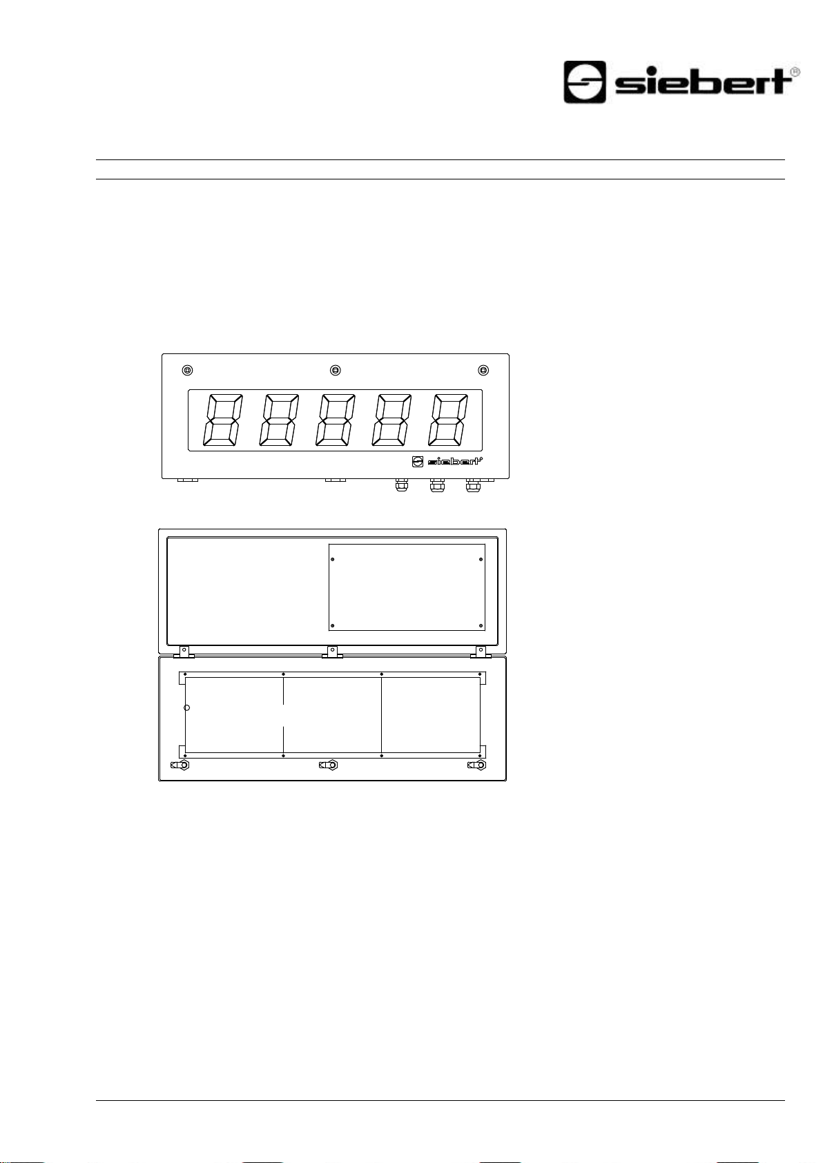
Unit construction
The following figure shows model type S302-05/10/xx-xxx/xx-xx as example for the other model types.
The front frame of the housing is locked with quick-action releases. When opening the unit the front
frame hinges downward.
The following figure shows the unit when open.
S302-xx/xx/xx-xxx/xx-YE
Units with double-sided display show the same information on the front and on the rear side.
Pos: 16 /Siebert/Seitenumbruch @ 0\ mod_1314194553878_0.docx @ 150 @ @ 1
BAL S302 EIP 1.11 7/21
Page 8

Pos: 17 /Siebert/Bedienungsanleitungen/ Serie S302/SX302/BAL ab 2017/Zahlenf ormat/ÜBS Zahlenformat @ 4\mod_1 489142000307_48.docx @ 27297 @ 1 @ 1
5 Number format
Pos: 18 /Siebert/Bedienungsanleitungen/ Serie S302/SX302/BAL ab 2017/Zahlenfor mat/S302 Zahlenformat EIP @ 4\mo d_1489142074760_48.docx @ 27304 @ @ 1
Numbers in this manual are displayed hexadecimal and decimal.
Hexadecimal numbers are always shown with the prefix '16 # 'and depending on the application with
leading zeros. The lowest value digit is on the right.
Example: The decimal number '10' equals '16#A' or '16#0A', the decimal number 100 equals '16#64'
or '16#0064'.
Pos: 19 /Siebert/Bedienungsanleitungen/ Serie S302/SX302/BAL ab 2017/IP-Eins tellungen/ÜBS IP-Einstellungen @ 4\ mod_1489143127692_48.docx @ 27310 @ 1 @ 1
IP-Einstellungen
6 IP settings
Decimal numbers do not have a special marking.
Pos: 21 /Siebert/Bedienungsanleitungen/ Serie S302/SX302/BAL ab 2017/IP-Eins tellungen/S302 IP-Einstellungen EIP ab Version 1.10 @ 4\mod_149449321867 2_48.docx @ 29054 @ @ 1
The following parameters are set in the factory setting:
IP address: 192.168.20.250
Subnet mask: 255.255.255.0
Gateway: 0.0.0.0
DHCP: Off
The values can be changed in an engineering framework (for example Rockwell Studio 5000).
Alternatively, you can change the IP settings using the program 'EtherNet/IP Tool'. You find the
program on the data carrier included in delivery as a ZIP archive file or on www.siebert-group.com.
After unpacking this file, the program 'EthernetIPTool.exe' can be run without installation.
After the program is started the following window opens and an automatic search for EtherNet/IPdevices is started. For a new search click on the 'Refresh' button on the top right.
Double-clicking on the display whose settings you want to change opens the following window:
BAL S302 EIP 1.11 8/21
Page 9

Enter the desired IP settings and click the 'OK' button. After successful configuration the following
window opens:
After that the display carries out a restart and can be accesses via the new IP settings.
The windows is closed by clicking 'OK' once and a new search for EtherNet/IP-devices starts.
Pos: 22 /Siebert/Seitenumbruch @ 0\ mod_1314194553878_0.docx @ 150 @ @ 1
BAL S302 EIP 1.11 9/21
Page 10

Parameter
Originator to Target (O T)
Target to Originator (T O)
Instance ID
150
100
Data size
6 bytes
0 bytes
Channel
Address
Description
Property
%QW0
2 bytes property identifier
Value
%QD1
4 bytes value signed
16 bit Property
32 bit signed number
%QW0 = 16#0100
%QD1 = 16#0000_000F (equals with the decimal number '+15')
%QB0
%QB1
%QB2
%QB3
%QB4
%QB5
16#00
16#01
16#0F
16#00
16#00
16#00
16 bit Property
32 bit signed number
%QW0 = 16#0100
%QD1 = 16#FFFF_FFF1 (equals with the decimal number '-15')
%QB0
%QB1
%QB2
%QB3
%QB4
%QB5
16#00
16#01
16#F1
16#FF
16#FF
16#FF
Pos: 23 /Siebert/Bedienungsanleitungen/ Serie S302/SX302/BAL ab 2017/Datenf ormat/ÜBS Datenformat @ 4\mod_14891 44336829_48.docx @ 27323 @ 1 @ 1
Datenformat
7 Data format
Pos: 24 /Siebert/Bedienungsanleitungen/ Serie S302/SX302/BAL ab 2017/Datenf ormat/S302 Datenformat EIP @ 4\mod_ 1489144370680_48.docx @ 27330 @ @ 1
The EDS data file is included in delivery or see on www.siebert-group.com.
The name of the display is 'S302-YE' and it uses the following settings:
The display always receives 6 bytes: 4 bytes for the value and 2 bytes, which specify the meaning of
the sent value. The following E/A-image is used:
Example 1: The decimal number '15' has to be shown on the display.
As Property 16#0100' and as Value '16#0000_000F' has to be send.
Because EtherNet/IP uses the byte order little-endian the bytes are sent as follows:
Example 2: The decimal number '-15' has to be shown on the display.
As Property '16#0100' and as Value '16#FFFF_FFF1' has to be send.
Because EtherNet/IP uses the byte order little-endian the bytes are sent as follows:
The possible display types (Properties) are described in the chapter 'Setting the display type via
Properties'.
Pos: 25 /Siebert/Seitenumbruch @ 0\ mod_1314194553878_0.docx @ 150 @ @ 1
BAL S302 EIP 1.11 10/21
Page 11

LED
Status
Meaning
off
offline
no IP address assigned
on (green)
online
one or several connections established
blinking (green)
online
no connection established
on (red)
fatal error
duplicate IP address
blinking (red)
timeout
timeout for one or more connections
LED
Status
Meaning
Off
offline
no power supply
on (green)
configuation
scanner in Run-Mode
blinking (green)
configuration
module not configured or scanner in idle state
on (red)
error
restart required
blinking (red)
error
restart required
Example on a 4-digit display
Until the first time user data is received, the display shows a frame on its
display alternating with the above status messages.
Underflow: The value sent to the display cannot be displayed on the
display. For example, the value '-1500' cannot be displayed on a four-digit
device.
Overflow: The value sent to the display cannot be displayed on the display.
For example, the value '-26550' cannot be displayed on a four-digit device.
Pos: 26 /Siebert/Bedienungsanleitungen/ Serie S302/SX302/BAL ab 2017/Meldung en der Anzeige/ÜBS Meldungen der Anzeig e @ 4\mod_1489146011857_48.doc x @ 27336 @ 1 @ 1
Meldungen
8 Messages on the display
Pos: 27 /Siebert/Bedienungsanleitunge n/Serie S302/SX302/BAL ab 2017/Meldung en der Anzeige/S302 Meldungen der A nzeige EIP ab Version 1.10 @ 4\mod_ 1494503081204_48.docx @ 29070 @ @ 1
The status of the EtherNet/IP connection is indicated by the status LEDs on the right side and on the
left side of the two RJ45 sockets.
LED NS (on the left side of the RJ45 socket of Port P1)
LED MS (on the right side of the RJ45socket of Port P2):
If connection fails or problems occur during operation, the display shows error ''. Possible causes
are IP problems caused by wrong network parameters, multiple assigned device names, commanding
of not defined properties or other fieldbus faults.
Once the connection has been established, the following messages can be displayed:
Pos: 29 /Siebert/Seitenumbruch @ 0\ mod_1314194553878_0.docx @ 150 @ @ 1
BAL S302 EIP 1.11 11/21
Page 12

Meaning
Property number
Data type
Default value
Offset
2 (16#02)
SINT32
0 (16#00)
Scale Factor
3 (16#03)
SINT16
1 (16#01)
Divisor
12 (16#0C)
UINT16 (unsigned)
1 (16#01)
Pos: 30 /Siebert/Bedienungsanleitungen/ Serie S302/SX302/BAL ab 2017/Einstellu ng der Darstellungsart über Properties/ÜB S Einstellung der Darstellungsart üb er Properties @ 4\mod_1489148312135 _48.docx @ 27349 @ 1 @ 1
9 Setting the display type via Properties
Pos: 31 /Siebert/Bedienungsanleitungen/ Serie S302/SX302/BAL ab 2017/Einstellu ng der Darstellungsart über Properties/S 302 Einleitungssatz EIP @ 4\mod_148 9148514198_48.docx @ 27356 @ @ 1
Each number, which is sent to the display via EtherNet/IP, is sent together with a Property value. This
value defines how the transmitted number is interpreted by the display.
In this case the Property value has the structure '%QW0' = '16#01nn'. The value of the High-Byte is
always 16#01, the Low Byte is set according to the desired function.
The following values are allowed for 'nn'.
Note: After a restart all settings of the settings of the display type via Properties are reset to their
default values.
Pos: 32 /Siebert/Bedienungsanleitu ngen/Serie S302/SX302/BAL ab 2017/Einst ellung der Darstellungsart über Properties /S302 Anzuzeigende Zahl EIP @ 4\m od_1489149678759_48.docx @ 2736 2 @ 2 @ 1
Anzuzeigend
Number to be displayed
Raw Value (property number 0 (16#00))
A number marked by this property is interpreted as a numerical value, which is displayed on the
display according to the set parameters.
Pos: 33 /Siebert/Bedienungsanleitungen/ Serie S302/SX302/BAL ab 2017/Einstellu ng der Darstellungsart über Properties /S302 Dezimalpunkte Decimal Dots (prop erty number 1) EIP @ 4\mod_14891500 19926_48.docx @ 27369 @ 2 @ 1
Decimal Dots
Decimal points
Decimal Dots (property number 1 (16#01))
The number and position of the decimal points can be defined with the help of a bit mask. For
example, multiple decimal points can be used to display a date or codes.
A set bit corresponds with a set decimal point.
The least significant bit corresponds to the decimal point of the least significant digit. If, for example,
the number '1234' is to be displayed with a decimal point between the 100th and the 10th digit, the bit
mask must be set to the value '0x04' and '12 .34 'appears on the display.
Pos: 34 /Siebert/Bedienungsanleitungen/ Serie S302/SX302/BAL ab 2017/Einstellu ng der Darstellungsart über Properties /S302 Offset, Skalenfactor (Multiplikator) und Divisor (property numbers 2, 3 und 12) EIP @ 4\mod_1489150210493_48. docx @ 27376 @ 2 @ 1
Offset, scale factor (multiplier), and divisor (property numbers 2 (16#02), 3 (16#03) and 12 (16#0C))
The formula that can be stored in the display allows you to display values in other units, such as
degrees Fahrenheit in degrees Celsius, kilograms in tons, miles in kilometers, or adding an offset.
This initialization parameter consists of the values offset, scale factor (multiplier) and divisor.
The calculation is based on the following linear function:
Displayed value = offset + scale factor (multiplier) / divisor x sent value
As a scale factor, integers are possible. Other factors can be formed by a combination of 'Scale
Factor' and 'Divisor'. For example, a multiplication with '13, 42 'can be generated by the scale factor'
1342 (16#053E) 'and divisor' 100 ' (16#64).
Pos: 35 /Siebert/Bedienungsanleitungen/ Serie S302/SX302/BAL ab 2017/Einstellu ng der Darstellungsart über Properties/S 302 Schwellenwerte Range (property n umbers 4 und 5) EIP @ 4\mod_148915 1036569_48.docx @ 27383 @ 2 @ 1
BAL S302 EIP 1.11 12/21
Page 13

Meaning
Property number
Data type
Default values
Upper bound
4 (16#04)
SINT32
-2147483648 (16#80000000)
Lower bound
5 (16#05)
SINT32
-2147483648 (16#80000000)
Meaning
Property number
Data type
Default value
Minimum number of digits
10 (16#0A)
Unsigned
1 (16#01)
Minimum width
11 (16#0B)
Unsigned
30 (16#1E)
Threshold values
Range (property numbers 4 (16#04) und 5 (16#05))
This initialization value defines the upper and lower thresholds at which the display automatically
changes its display attribute.
No threshold values are defined in the delivery state. The default value commands this.
If a value is received outside the defined thresholds, the display automatically changes from 'standard'
to 'out of range'. As soon as a value is received within the defined limits, the display returns to
standard.
Example: For a temperature value display, the display should change its display mode, both when the
temperature falls below 0 degrees Celsius and when it exceeds 100 degrees Celsius. For this, the
values Upper bound = 100 (16#00000064) and Lower bound = 0 (16#00000000) must be entered.
Pos: 36 /Siebert/Bedienungsanleitunge n/Serie S302/SX302/BAL ab 2017/Einstellu ng der Darstellungsart über Properties/S 302 Flags Property number 6 (16#06) EI P @ 4\mod_1489162547096_48.doc x @ 28601 @ 2 @ 1
Flags
Flags (property number 6 (16#06))
In this initialization value (type INT16) display properties are set.
Pos: 37 /Siebert/Bedienungsanleitungen/ Serie S302/SX302/BAL ab 2017/Einstellu ng der Darstellungsart über Properties/S 302 Attribute für Blinken und Blinkmodi (pr operty numbers 7 (16#07) und 9 (1 6#09)) @ 4\mod_1489162858568_48.doc x @ 28608 @ 2 @ 1
Attributes for flashing and blinking modes (property numbers 7 (16#07) and 9 (16#09))
This initialization values define the blinking modes for the standard display (property number 7
(16#07)) and the 'Out of range' display (property number 9 (16#09)).
See chapter flashing modes.
See chapter flags.
Pos: 38 /Siebert/Bedienungsanleitungen/ Serie S302/SX302/BAL ab 2017/Einstellu ng der Darstellungsart über Properties/S 302 Format (property numbers 10 (16 #0A) und 11 (16#0B)) EIP @ 4\mod_14 89163419129_48.docx @ 28615 @ 2 @ 1
Format (property numbers 10 (16#0A) and 11 (16#0B))
These two initialization parameters define the alignment of the displayed values and the number of
leading zeros.
The minimum number of digits displayed is defined with 'Minimum number of digits'. If the value to be
displayed has fewer digits than 'Minimum number of digits', the display is filled with zeros on the left
side.
Example: for a six-digit display, 'Minimum number of digits' is set to 6. If the number '1234 (16 # 04D2)'
is sent to the display, '001234' appears in the display.
The 'Minimum Width' defines the minimum number of digits used for display. If the number
representation contains fewer characters (including the sign), the space is filled with spaces on the left
side.
Pos: 39 /Siebert/Seitenumbruch @ 0\ mod_1314194553878_0.docx @ 150 @ @ 1
Example: to display a number on the left-hand side, set the parameter 'Minimum Width' to '1'.
BAL S302 EIP 1.11 13/21
Page 14

Effect
Attribute value
25% of the basic brightness
85 (16#0000_0055)
50% of the basic brightness
170 (16#0000_00AA)
100% of the basic brightness
255 (16#0000_00FF)
Pulsation
0 (16#0000_0000)
Brief flashing
3 (16#0000_0003)
Fast flashing
51 (16#0000_0033)
Slow flashing
15 (16#0000_000F)
Short darkening
63 (16#0000_003F)
Low beaming
27 (16#0000_001B)
High beaming
228 (16#0000_00E4)
25% of the basic brightness, orange
21845 (16#0000_5555)
50% of the basic brightness, orange
43690 (16#0000_AAAA)
100% of the basic brightness, orange
65535 (16#0000_FFFF)
Slow flashing (off – on), red
15 (16#0000_000F)
Slow inverse flashing (on – off), green
61440 (16#0000_F000)
Flashing red/green alternately
61455 (16#0000_F00F)
Pos: 40 /Siebert/Bedienungsanleitungen/ Serie S302/SX302/BAL ab 2017/Blinkmo di und Anzeigenattribute/ÜBS Blinkmodi und Anzeigenattribute @ 4\mod_148 9152312459_48.docx @ 27400 @ 1 @ 1
B
10 Flashing modes and display attributes
Pos: 41 /Siebert/Bedienungsanleitungen/ Serie S302/SX302/BAL ab 2017/Blinkmo di und Anzeigenattribute/S302 Blimnkm odi und Anzeigenattribute EIP ab Version 1.10 @ 4\mod_1494503501235_48.d ocx @ 29076 @ @ 1
The display can show the values to be displayed in a plurality of brightness and blinking patterns,
which are referred to as 'display attribute'.
For the initialization parameters, two blocks are defined: a block for 'standard attributes' (property
number 7 (16#07)), the other for 'out of range attributes' (property number 9 (16#09)).
The least significant byte is used for displays with monochrome LEDs, all other bytes are set to 1. So
for example, the following typical display effects can be defined:
In the case of displays with multicolor LEDs (red and green), the attribute for the red color is set with
the least significant byte and the attribute for the green color with the next higher byte. The meaning of
the bytes for red and green is identical.
With the same attributes for red and green the display shines orange. Diverse mixed colors, flashing
effects and color changing effects can be defined by different attributes, for example:
The dark switching is possible by the global 'property 4' (16#04). Here the decimal point of the least
significant decade flashes.
Pos: 43 /Siebert/Seitenumbruch @ 0\ mod_1314194553878_0.docx @ 150 @ @ 1
BAL S302 EIP 1.11 14/21
Page 15

Bit number
Meaning
Default
31…9
8 7 6 5 4 3 2 1 0 : : : : : : : : : :
: : : : : : : : : 0 Circumferential frame off
: : : : : : : : : 1 Circumferential frame on
X : : : : : : : : : : : : : : : : : 0
Underflow off
: : : : : : : : 1 Underflow on
X : : : : : : :
: : : : : : : 0 Overflow off
: : : : : : : 1
Overflow on
X : : : : : : : : : : : 0
Invalid initial value off
X
: : : : : : 1 Invalid initial value on
: : : : : :
: : : : : 0 Smart-Dot-Function off
: : : : : 1
Smart-Dot-Function on
X : : : : :
: : : 0 0
The decimal places are trancated.*
: : : 0 1
The decimal places are rounded up*
: : : 1
0
The decimal places are rounded down.*
: : : 1 1
The decimal places are rounded commercially.*
X : : 0
Leading zeros off
: : 1 Leading zeros on
X : :
: 0 Value is displayed in decimal form
X : 1
Value is displayed in hexadecimal form
: 0
Without function. The bits are to be set to '0
X
* only with activated Smart-Dot-Function
Pos: 44 /Siebert/Bedienungsanleitunge n/Serie S302/SX302/BAL ab 2017/Flags/Ü BS Flags @ 4\mod_1489153060367_48. docx @ 27419 @ 1 @ 1
Flags
11 Flags
Pos: 45 /Siebert/Bedienungsanleitungen/ Serie S302/SX302/BAL ab 2017/Flags/S3 02 Flags ab Version 1.10 @ 4\mod_ 1494503700675_48.docx @ 29082 @ @ 1
Leading zeros
On the places in front of the value is shown automatically
Smart-Dot-Function
The display automatically moves the decimal point so that the decimal value is displayed completely
when the value exceeds the maximum display capacity.
Invalid initial value
If the value sent to the display is invalid, is shown on each position.
Overflow
If the value sent to the display is that large that it cannot be displayed on the display is shown on
each position on the upper segments.
If the overflow function is deactivated, the value that can be displayed as large as possible is
displayed for a larger number than can be displayed. For example: numbers larger or equal 9999 are
always displayed with '9999' on a four-digit display.
Underflow
If the value sent to the display is that small that it cannot be displayed on the display is shown on
each position of the lower segments.
If the underflow function is deactivated the value that can be displayed as small as possible is
displayed for a smaller number than can be displayed. For example: numbers smaller or equal -9999
are always displayed with '-999' on a four-digit display.
Circumferential frame
Until user data is received for the first time the display alternately displays or various status
messages on its display.
Pos: 47 /Siebert/Seitenumbruch @ 0\ mod_1314194553878_0.docx @ 150 @ @ 1
BAL S302 EIP 1.11 15/21
Page 16

Global property number
Meaning
Allowed values
1
Select luminosity value
0 (16#0) = Standard brightness (default)
1 (16#1) = Out of range brightness
2
Standard-luminosity
0 (16#0) = off
…
8 (16#8) = middle luminosity (default)
…
15 (16#F) = maximum luminosity
3
'out of range'-luminosity
0 (16#0) = off
…
8 (16#8) = middle luminosity (default)
…
15 (16#F) = maximum luminosity
4
Blanking of the display
0 (16#0) = Display is dark
all others: display lights (default)
16 bit Property
32 bit signed number
%QW0 = 16#0002
%QD1 = 16#0000_000A (equals with the decimal number '+10')
%QB0
%QB1
%QB2
%QB3
%QB4
%QB5
16#02
16#00
16#0A
16#00
16#00
16#00
16 bit Property
32 bit signed number
%QW0 = 16#0004
%QD1 = 16#0000_0000 (equals with the decimal number '0')
%QB0
%QB1
%QB2
%QB3
%QB4
%QB5
16#04
16#00
16#00
16#00
16#00
16#00
Pos: 48 /Siebert/Bedienungsanleitunge n/Serie S302/SX302/BAL ab 2017/Einstellu ng der Grundhelligkeit/ÜBS Einstellung d er Grundhelligkeit @ 4\mod_148915 5927576_48.docx @ 27438 @ 1 @ 1
Einstellung der
12 Setting the basic brightnesst
Pos: 49 /Siebert/Bedienungsanleitunge n/Serie S302/SX302/BAL ab 2017/Einst ellung der Grundhelligkeit/S302 Einstellung d er Grundhelligkeit EIP @ 4\mod_1 489156057026_48.docx @ 27445 @ @ 1
The basic brightness can be set with the value Property = '16#000x'.
The following values are allowed for x:
During darkness, the decimal point of the least significant decade flashes.
Example1: the standard luminosity has to be changed to '10':
As Property '16#0002' and as Value '16#0000_000A' are to be send.
Because EtherNet/IP uses the byte order little-endian the bytes are sent as follows.
Example 2: switch the display to dark:
As Property '16#0004' and as Value '16#0000_0000' are to be send.
Because EtherNet/IP uses the byte order little-endian the bytes are sent as follows:
Pos: 50 /Siebert/Seitenumbruch @ 0\ mod_1314194553878_0.docx @ 150 @ @ 1
BAL S302 EIP 1.11 16/21
Page 17

Pos: 51 /Siebert/Bedienungsanleitungen/ Serie S302/SX302/BAL ab 2017/Technisch e Daten/ÜBS Technische Daten @ 4 \mod_1489157315364_48.docx @ 27 451 @ 1 @ 1
Technische
13 Technical data
Pos: 52 /Siebert/Bedienungsanleitungen/ Serie S302/SX302/BAL ab 2017/Technisch e Daten/S302 Feldbus EIP @ 4\mod_ 1494582948948_48.docx @ 29094 @ 2 @ 1
Felkd
Fieldbus
Internet EtherNet/IP
MAC address Die MAC for the fieldbus coupling can be found
on the control computer of the device.
Pos: 53 /Siebert/Bedienungsanleitungen/ Serie S302/SX302/BAL ab 2017/Technisch e Daten/S302 Technische Daten EIP @ 4\mod_1489157351310_48.docx @ 2 7458 @ 222 @ 1
Power supply
The screw-type terminals for the power supply are located on the power supply unit in the bottom
section of the housing. They have the following designations:
Devices for a power supply 115 V AC or 230 V AC L, N and PE
Devices for a power supply 24 V DC +, – and PE
Housing colors
Case front RAL 5002ultramarine
Case rear part RAL 7035 light grey
Integrated switch Yes
Ambient conditions
Operating temperature 0…55 °C, with heating -20…55 °C
Storage temperature -30…85 °C
Relative humidity max. 95 % (non condensing)
Pos: 54 /Siebert/Bedienungsanleitungen/ Serie S302/SX302/BAL ab 2017/Technisch e Daten/S302 Geräteausführung EIP @ 4\mod_1489159084987_48.docx @ 2 7464 @ 2 @ 1
Gerätreausführung
BAL S302 EIP 1.11 17/21
Page 18

S302
– / / – / – : : : : : : : : : : : : :
No dimension symbol
0 : : : : : : : : : : : : Dimension symbol
F : : : : : : : : : : : : : : : : : : : : : : : :
1 digit 1 : : : : : : : : : : :
2 digits
2 : : : : : : : : : : : : : : : : : : : : : :
8 digits
8 : : : : : : : : : : : : : : : : : : : : : :
Character height 57 mm
0 6 : : : : : : : : :
Character height 100 mm
1 0 : : : : : : : : :
Character height 160 mm
1 6 : : : : : : : : :
Character height 250 mm
2 5 : : : : : : : : :
: : : : : : : :
:
LED standard
0 : : : : : : :
:
LED for outdoor use
2 : : : : : : : :
: : : : : : : :
Character color red
R : : : : : : :
Character color green
G : : : : : : :
Character color white
W : : : : : : :
Character color red/green/orange switchable
M : : : : : : : : : : : : : :
Display readable on one side
1 : : : : : :
Display readable on both sides
2 : : : : : :
: : : : : : Housing Steel sheet, powder-coated
0 : : : : : Housing Steel sheet, 2-layer powder-coated
1 : : : :
:
Housing Stainless steel V2A, powder-coated
2 : : : :
:
Housing Stainless steel V2A, brushed
3 : : : : : Housing Stainless steel V4A, brushed
5 : : : :
:
: : : : :
Protection type IP54
0 : : : :
Protection type IP65
1 : : : :
Protection type IP54 with climate adjustment
2 : : : :
Protection type IP54 with climate adjustment and heating
4 : : : : : : : :
Wall mounting, Cable entry point from the bottom
0 : : :
Wall mounting, Cable entry point from the top
1 : : :
Hanging installation, Cable entry point from the bottom
2 : : :
Hanging installation, Cable entry point from the top
3 : : :
Wall- and Hanging installation, Cable entry point from the bottom
4 : : :
Wall- and Hanging installation, Cable entry point from the top
5 : : :
: : : Power supply 230 V AC ±15 %, 50 Hz
A : : Power supply 24 V DC ±15 %
B : : Power supply 115 V AC ±15 %, 60 Hz
C :
:
: :
Interface
Y
E
Unit properties
The model designation is structured as follows
Pos: 55 /Siebert/Bedienungsanleitungen/ Serie S302/SX302/BAL ab 2017/Technisch e Daten/S302 Maximale Leistungsauf nahme EIP @ 4\mod_1489159858651_ 48.docx @ 27471 @ 2 @ 1
BAL S302 EIP 1.11 18/21
Page 19

Units with one-sided display
[VA]1)
Units with double-sided display
[VA]1)
1 digit
1 digit
S302-x1/10/xx-1xx/xx-xx
12 S302-x1/10/xx-2xx/xx-xx
16
S302-x1/16/xx-1xx/xx-xx
22 S302-x1/16/xx-2xx/xx-xx
35
S302-x1/25/xx-1xx/xx-xx
26 S302-x1/25/xx-2xx/xx-xx
42
2 digits
2 digits
S302-x2/06/xx-1xx/xx-xx
12 S302-x2/06/xx-2xx/xx-xx
15
S302-x2/10/xx-1xx/xx-xx
15 S302-x2/10/xx-2xx/xx-xx
21
S302-x2/16/xx-1xx/xx-xx
37 S302-x2/16/xx-2xx/xx-xx
66
S302-x2/25/xx-1xx/xx-xx
46 S302-x2/25/xx-2xx/xx-xx
83
3 digits
3 digits
S302-x3/06/xx-1xx/xx-xx
13 S302-x3/06/xx-2xx/xx-xx
17
S302-x3/10/xx-1xx/xx-xx
17 S302-x3/10/xx-2xx/xx-xx
26
S302-x3/16/xx-1xx/xx-xx
51 S302-x3/16/xx-2xx/xx-xx
92
S302-x3/25/xx-1xx/xx-xx
63 S302-x3/25/xx-2xx/xx-xx
116
4 digits
4 digits
S302-x4/06/xx-1xx/xx-xx
14 S302-x4/06/xx-2xx/xx-xx
19
S302-x4/10/xx-1xx/xx-xx
21 S302-x4/10/xx-2xx/xx-xx
33
S302-x4/16/xx-1xx/xx-xx
64 S302-x4/16/xx-2xx/xx-xx
119
S302-x4/25/xx-1xx/xx-xx
79 S302-x4/25/xx-2xx/xx-xx
150
5 digits
5 digits
S302-x5/06/xx-1xx/xx-xx
15 S302-x5/06/xx-2xx/xx-xx
21
S302-x5/10/xx-1xx/xx-xx
23 S302-x5/10/xx-2xx/xx-xx
38
S302-x5/16/xx-1xx/xx-xx
77 S302-x5/16/xx-2xx/xx-xx
146
S302-x5/25/xx-1xx/xx-xx
96 S302-x5/25/xx-2xx/xx-xx
184
6 digits
6 digits
S302-x6/06/xx-1xx/xx-xx
16 S302-x6/06/xx-2xx/xx-xx
23
S302-x6/10/xx-1xx/xx-xx
26 S302-x6/10/xx-2xx/xx-xx
43
S302-x6/16/xx-1xx/xx-xx
91 S302-x6/16/xx-2xx/xx-xx
173
S302-x6/25/xx-1xx/xx-xx
113 S302-x6/25/xx-2xx/xx-xx
217
7 digits
7 digits
S302-x7/06/xx-1xx/xx-xx
17 S302-x7/06/xx-2xx/xx-xx
25
S302-x7/10/xx-1xx/xx-xx
30 S302-x7/10/xx-2xx/xx-xx
51
S302-x7/16/xx-1xx/xx-xx
104 S302-x7/16/xx-2xx/xx-xx
200
S302-x7/25/xx-1xx/xx-xx
130 S302-x7/25/xx-2xx/xx-xx
250
8 digits
8 digits
S302-x8/06/xx-1xx/xx-xx
18 S302-x8/06/xx-2xx/xx-xx
27
S302-x8/10/xx-1xx/xx-xx
32 S302-x8/10/xx-2xx/xx-xx
55
Max. power consumption
1)
The values given are approximate values. For units with built-in heating, the values for power consumption specified in the
table increase by approx. 10 – 100 VA (exact values on request), depending on the unit size.
2)
The power consumption for the unit version model S302-xx/xx/0x-xxx/xx-xx is also valid for the unit version
S302-xx/xx/2x-xxx/xx-xx (LEDs for external use).
Pos: 56 /Siebert/Bedienungsanleitungen/ Serie S302/SX302/BAL ab 2017/Technisch e Daten/S302 Abmessungen und Ge wichte @ 4\mod_1489160537405_48.doc x @ 27478 @ 2 @ 1
BAL S302 EIP 1.11 19/21
Page 20

1 digit
a [mm]
b [mm]
c [mm]
d [mm]
Ø [mm]
Weight [kg]1)
S302-01/10/xx-1xx/xx-xx
330
245
110
16 7 6
S302-01/16/xx-1xx/xx-xx
390
300
110
20 9 7
S302-01/25/xx-1xx/xx-xx
570
400
110
20 9 11
2 digits
1 digit + dimension
S302-02/06/xx-1xx/xx-xx
-
300
185
110
16 7 5
S302-02/10/xx-1xx/xx-xx
S302-F1/10/xx-1xx/xx-xx
330
245
110
16 7 6
S302-02/16/xx-1xx/xx-xx
S302-F1/16/xx-1xx/xx-xx
390
300
110
20 9 7
S302-02/25/xx-1xx/xx-xx
S302-F1/25/xx-1xx/xx-xx
570
400
110
20 9 11
3 digits
2 digits + dimension
S302-03/06/xx-1xx/xx-xx
S302-F2/06/xx-1xx/xx-xx
300
185
110
16 7 5
S302-03/10/xx-1xx/xx-xx
S302-F2/10/xx-1xx/xx-xx
480
245
110
16 7 8
S302-03/16/xx-1xx/xx-xx
S302-F2/16/xx-1xx/xx-xx
670
300
110
20 9 11
S302-03/25/xx-1xx/xx-xx
S302-F2/25/xx-1xx/xx-xx
1030
400
110
20 9 18
4 digits
3 digits + dimension
S302-04/06/xx-1xx/xx-xx
S302-F3/06/xx-1xx/xx-xx
300
185
110
16 7 5
S302-04/10/xx-1xx/xx-xx
S302-F3/10/xx-1xx/xx-xx
480
245
110
16 7 8
S302-04/16/xx-1xx/xx-xx
S302-F3/16/xx-1xx/xx-xx
670
300
110
20 9 11
S302-04/25/xx-1xx/xx-xx
S302-F3/25/xx-1xx/xx-xx
1030
400
110
20 9 18
5 digits
4 digits + dimension
S302-05/06/xx-1xx/xx-xx
S302-F4/06/xx-1xx/xx-xx
400
185
110
16 7 6
S302-05/10/xx-1xx/xx-xx
S302-F4/10/xx-1xx/xx-xx
680
245
110
16 7 10
S302-05/16/xx-1xx/xx-xx
S302-F4/16/xx-1xx/xx-xx
960
300
110
20 9 14
S302-05/25/xx-1xx/xx-xx
S302-F4/25/xx-1xx/xx-xx
1500
400
110
20 9 24
6 digits
5 digits + dimension
S302-06/06/xx-1xx/xx-xx
S302-F5/06/xx-1xx/xx-xx
400
185
110
16 7 6
S302-06/10/xx-1xx/xx-xx
S302-F5/10/xx-1xx/xx-xx
680
245
110
16 7 10
S302-06/16/xx-1xx/xx-xx
S302-F5/16/xx-1xx/xx-xx
960
300
110
20 9 14
S302-06/25/xx-1xx/xx-xx
S302-F5/25/xx-1xx/xx-xx
1500
400
110
20 9 24
7 digits
6 digits + dimension
-
S302-F6/03/xx-1xx/xx-xx
300
185
110
16 7 5
S302-07/06/xx-1xx/xx-xx
S302-F6/06/xx-1xx/xx-xx
510
185
110
16 7 7
S302-07/10/xx-1xx/xx-xx
S302-F6/10/xx-1xx/xx-xx
870
245
110
16 7 12
S302-07/16/xx-1xx/xx-xx
S302-F6/16/xx-1xx/xx-xx
1100
300
110
20 9 16
S302-07/25/xx-1xx/xx-xx
S302-F6/25/xx-1xx/xx-xx
1730
400
110
20 9 28
8 digits
7 digits + dimension
S302-08/06/xx-1xx/xx-xx
S302-F7/06/xx-1xx/xx-xx
510
185
110
32 7 7
S302-08/10/xx-1xx/xx-xx
S302-F7/10/xx-1xx/xx-xx
870
245
110
32 7 12
Dimensions and weights
Units with one-sided display
The following figure shows unit versions S302-04/10/4x-1xx/xx-xx
and S302-F3/10/4x-1xx/xx-xx representing the other unit versions listed in the following table.
BAL S302 EIP 1.11 20/21
1)
The figures shown are approximate values.
Page 21

1 digit
a [mm]
b [mm]
c [mm]
Weight [kg]1)
S302-01/10/xx-2xx/xx-xx
330
245
170 9 S302-01/16/xx-2xx/xx-xx
390
300
170
11
S302-01/25/xx-2xx/xx-xx
570
400
170
17
2 digits
1 digit + dimension
S302-02/06/xx-2xx/xx-xx
-
300
185
170
7
S302-02/10/xx-2xx/xx-xx
S302-F1/10/xx-2xx/xx-xx
330
245
170
9
S302-02/16/xx-2xx/xx-xx
S302-F1/16/xx-2xx/xx-xx
390
300
170
11
S302-02/25/xx-2xx/xx-xx
S302-F1/25/xx-2xx/xx-xx
570
400
170
17
3 digits
2 digits + dimension
S302-03/06/xx-2xx/xx-xx
S302-F2/06/xx-2xx/xx-xx
300
185
170 7 S302-03/10/xx-2xx/xx-xx
S302-F2/10/xx-2xx/xx-xx
480
245
170
12
S302-03/16/xx-2xx/xx-xx
S302-F2/16/xx-2xx/xx-xx
670
300
170
17
S302-03/25/xx-2xx/xx-xx
S302-F2/25/xx-2xx/xx-xx
1030
400
170
27
4 digits
3 digits + dimension
S302-04/06/xx-2xx/xx-xx
S302-F3/06/xx-2xx/xx-xx
300
185
170
7
S302-04/10/xx-2xx/xx-xx
S302-F3/10/xx-2xx/xx-xx
480
245
170
12
S302-04/16/xx-2xx/xx-xx
S302-F3/16/xx-2xx/xx-xx
670
300
170
17
S302-04/25/xx-2xx/xx-xx
S302-F3/25/xx-2xx/xx-xx
1030
400
170
27
5 digits
4 digits + dimension
S302-05/06/xx-2xx/xx-xx
S302-F4/06/xx-2xx/xx-xx
400
185
170
8
S302-05/10/xx-2xx/xx-xx
S302-F4/10/xx-2xx/xx-xx
680
245
170
15
S302-05/16/xx-2xx/xx-xx
S302-F4/16/xx-2xx/xx-xx
960
300
170
21
S302-05/25/xx-2xx/xx-xx
S302-F4/25/xx-2xx/xx-xx
1500
400
170
36
6 digits
5 digits + dimension
S302-06/06/xx-2xx/xx-xx
S302-F5/06/xx-2xx/xx-xx
400
185
170 8 S302-06/10/xx-2xx/xx-xx
S302-F5/10/xx-2xx/xx-xx
680
245
170
15
S302-06/16/xx-2xx/xx-xx
S302-F5/16/xx-2xx/xx-xx
960
300
170
21
S302-06/25/xx-2xx/xx-xx
S302-F5/25/xx-2xx/xx-xx
1500
400
170
36
7 digits
6 digits + dimension
-
S302-F6/03/xx-2xx/xx-xx
300
185
170 7 S302-07/06/xx-2xx/xx-xx
S302-F6/06/xx-2xx/xx-xx
510
185
170 9 S302-07/10/xx-2xx/xx-xx
S302-F6/10/xx-2xx/xx-xx
870
245
170
18
S302-07/16/xx-2xx/xx-xx
S302-F6/16/xx-2xx/xx-xx
1100
300
170
24
S302-07/25/xx-2xx/xx-xx
S302-F6/25/xx-2xx/xx-xx
1730
400
170
42
8 digits
7 digits + dimension
S302-08/06/xx-2xx/xx-xx
S302-F7/06/xx-2xx/xx-xx
510
185
170 9 S302-08/10/xx-2xx/xx-xx
S302-F7/10/xx-2xx/xx-xx
870
245
170
18
Units with double-sided display
The following figure shows unit versions S302-04/10/4x-2xx/xx-xx
and S302-F3/10/4x-2xx/xx-xx representing the other unit versions listed in the following table.
Units with 57mm character height (S302-xx/06/xx-2xx/xx-xx) have 2 instead of 4 eyelets.
=== Ende der Liste für Textmarke Inhalt 2 ===
BAL S302 EIP 1.11 21/21
1)
The figures shown are approximate values.
 Loading...