

Page 1
GENERAL DESCRIPTION
The EWLP 120 data recorder is an electronic device designed to measure temperature, humidity or pressure from two
different locations.
Due to the use of a microprocessor it can
store up to 1600 reading points, with user
programmable storage intervals. Stored
data can be printed with messages in several languages.
The instrument can be connected to PTC
or Pt100 probes; alternatively the current
input port can be used for pressure or humidity. It is available in a 161x192 mm ABS
plastic case, 94 mm deep.
COMMANDS ON FRONT PANEL
(response to key pressure is delayed by
approximately 0.5 seconds).
RECORDING 1
The pressure of this key starts recording
related to sensor n. 1; the related led turns
on and the display indicates the value read
by probe 1.
A further key pressure stops recording related to sensor 1; the related led turns off
and the display indicates the value read by
the probe of sensor 2, when enabled, otherwise the OFF message is displayed.
RECORDING 2
The pressure of this key starts recording
related to sensor n. 2; the related led turns
on and the display indicates the value read
by probe 2.
A further key pressure stops recording related to sensor 2; the related led turns off.
When the two probes are set to STAND BY
(disabled data recording) the display indicates the OFF message.
When both probes are enabled (enabled
data recording) the led on indicates the
zone whose value is displayed, the blinking
reminds that the related zone is enabled for
recording.
CLEAR
The key pressure after print clears from
memory the recordings related to the report printed and enables the recording
again.
PRG
When held pressed for 3 seconds in
STAND BY (OFF message displayed) with
no stored data it allows to enter or exit parameters programming mode. In case
stored data are present, the display shows
the ErPr alarm code.
MUTE
The key pressure in data recording allows
to silence the alarm by disabling the related relay; the code on the display will continue to show the alarm presence.
▲ (UP)
When pressed in programming mode it allows to skip to the following parameter or
increase its value. In recording mode it selects to display the value related either to
sensor 1 or sensor 2.
▼ (DOWN)
When pressed in programming mode it allows to skip to the following parameter or
increase its value. In temperature recording
mode it selects to display the current time.
LABEL/VALUE
When pressed in parameters programming
mode it allows to switch from the parameter label display to its value, and vice-versa.
PRINT
The key pressure starts the printing of
recorded data; while printing the display
shows letter P (print), recording is suspended and all keys are disabled.
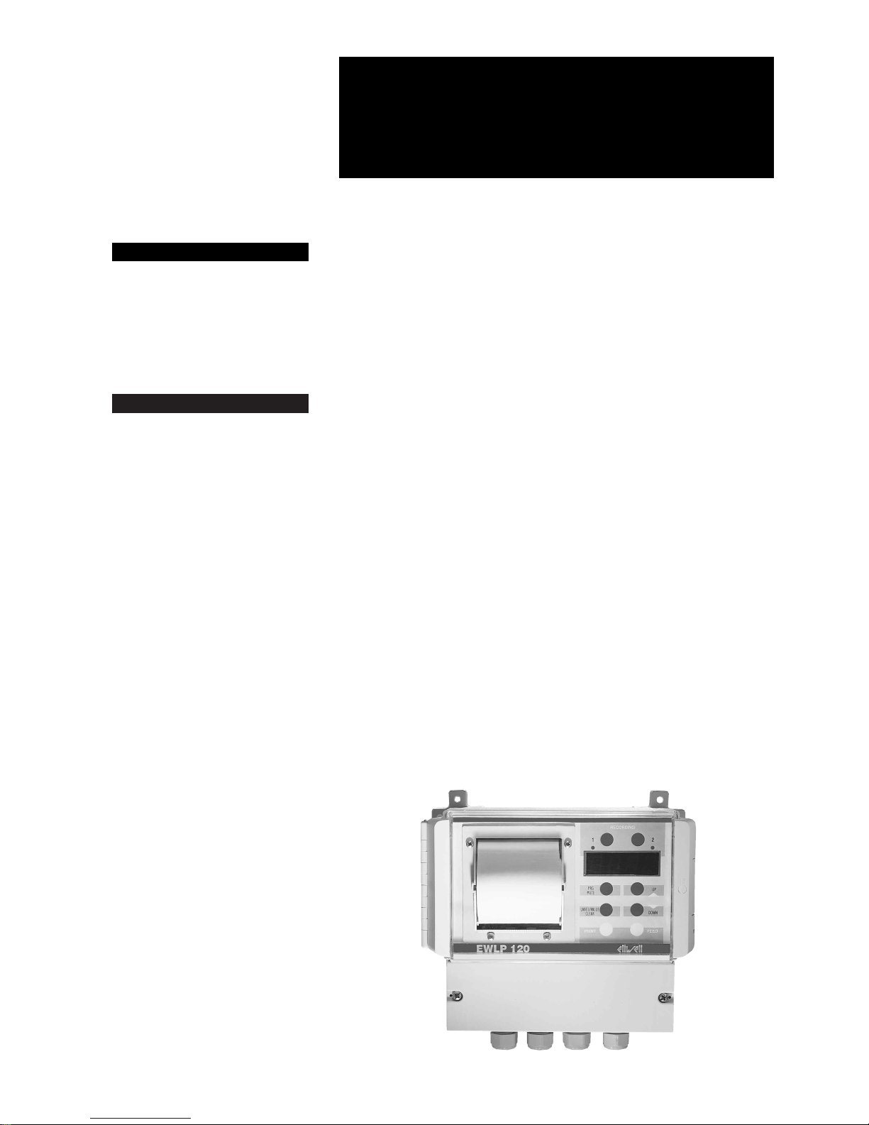
HOW IT IS MADE
WHAT IT IS
EWLP 120 is a data recorder capable to measure temperature, humidity or pressure from two different
locations.
It is provided with a micro gate input and a relay for alarm signal control.
EWLP 120
rel. 5/99 ing
temperature recorder
• Size: 161x192 mm, depth 94 mm
• Housing: ABS plastic
• Mount: wall mount through special
fixing holes
• Protection grade: IP65
• Connections: screw terminal block
• Storage: on non-volatile memory capacity 1.600 readings
• Printer type: 24 columns with 7x5
matrix on thermal non-photo sensitive paper, paper width 57 mm
• Outputs: on relay (in exchange) for
external alarm repetition
• Inputs: 2 PTC or PT100 temperature probes; the second input can
be matched with a humidity or
pressure input. One input for micro
gate and one for backup battery
• Resolution: 0.5 °C, 0.5 Bar and
0.5 %RH
• Accuracy: 0.5 °C, 0.5 Bar and
0.5 %RH
• Power supply: 230 Vac
Page 2

At the end of print the display shows the
messages OFF and “Prnt” (print) alternatively; a further key pressure repeats the
print while the pressure of key CLEAR rubs
all data from memory and restarts data
recording.
FEED
The pressure of this key allows to move the
paper forward.
PARAMETERS PROGRAMMING
Hold the “PRG” key pressed for 3 seconds
in STAND BY mode (OFF message displayed) and no data stored; the display
shows the first parameter (Po1). The pressure of the “UP” (or “DOWN”) key while in
programming mode allows to skip to the
following (previous) parameter or increase
(decrease) its value. The pressure of key
“Label/Value” while in parameters programming mode allows to switch from parameters label display to value display and
vice-versa. Hold button “PRG” pressed for
3 seconds to exit programming mode.
WARNING: new values are only stored
when programming mode is exited. Check
time indicated by parameters Po1 and Po2
to control the clock.
PARAMETERS DESCRIPTION
Po1: minutes setting (01…59).
Po2: hours setting (00…23).
Po3: weekday setting:
1 = Monday;
2 = Tuesday;
3 = Wednesday;
4 = Thursday;
5 = Friday;
6 = Saturday;
7 = Sunday.
Po4: month day setting (01…31).
Po5: month setting (01…12).
Po6: year setting.
Po7: setting of the instrument recognition
code (4 digits maximum); this code appears as heading on every report.
Po8: data storage interval setting; values
from 1…240 minutes (default 30 minutes).
Po9: maximum alarm value setting for sensor n. 1; when the threshold is exceeded
after the delay time set through parameter
Po14, the alarm relay is triggered and the
alarm value related to letter P is printed if
the print is enabled through parameter
Po13.
Po10: minimum alarm value setting for
sensor n. 1; when the threshold is exceeded after the delay time set through parameter Po14, the alarm relay is triggered
and the alarm value related to letter N is
printed if the print is enabled through parameter Po13. The value of this parameter
shall be lower than or equal to P9; otherwise the negative set will be set to P9
when programming mode is exited.
Po11: maximum alarm value setting for
sensor n. 2; when the threshold is exceeded after the delay time set through parameter Po14, the alarm relay is triggered
and the alarm value related to letter P is
printed if the print is enabled through parameter Po13.
Po12: minimum alarm value setting for
sensor n. 2; when the threshold is exceeded after the delay time set through parameter Po14, the alarm relay is triggered
and the alarm value related to a symbol is
printed if the print is enabled through parameter Po13.
The value of this parameter shall be lower
than or equal to P11; otherwise the negative set will be set to P11 when programming mode is exited.
Po13: print enabled in case of alarm (default 0) where:
0 = alarm print disabled;
1 = print enabled for maximum alarms only
(Po9 - Po11);
2 = print enabled for minimum alarms
only(Po10 - Po12);
3 = print enabled for minimum and maximum alarms (Po9 - Po10 - Po11 - Po12).
Po14: alarm delay time and open door setting; values from 1…60 minutes (default 30
minutes).
Po15: allows to change the value read by
probe n. 1; values from –5…5 (default 0).
Po16: allows to change the value read by
probe n. 2; values from –5…5 (default 0).
Po17: language selection for printed messages (default 1):
1 = Italian;
2 = English;
3 = French;
4 = German;
5 = Spanish.
NOTE: the measurement unit related to
probe n. 2 is automatically selected (°F or
%RH or Bar) according to the configuration
of dip switch KD1.
ALARM CODES
EE01: memory error - possible loss of all
set data, alarm relay triggered and data
recording stopped. After this alarm print
the recorded data - that could be wrong and at the end of the report the message
“LOST RECORDS - CHECK PARAMETERS” will be printed.
Device check procedure: enter programming mode and check the set parameters;
if they correspond to those previously set,
change one parameter; in case the alarm is
still present when exiting programming
mode, contact an authorised servicing
centre otherwise re-enter programming
mode and correct previously changed
data.
FULL: full memory. The alarm relay is triggered. The recorded data need to be printed. 100 more recordings are available in
the device since the alarm appears. When
the memory is full recording continue overwriting the first recorded data. At the end
of print the message “PARTIAL RECORDINGS DUE TO FULL MEMORY” will be
printed.
EndP: paper missing: slightly open the
side pads, extract the paper support. To insert a new paper roll fit the support be-
tween the two pads with a light pressure.
Then insert the paper into the upper slot
and load it using the FEED button.
If this alarm occurred while printing, press
the PRINT key to restart the report, that will
begin from day on which it was interrupted.
ALP1: alarm related to probe n. 1 and
alarm relay triggering. On the report the
alarm occurrence will be indicated by the
following symbols:
Z (zone 1 or 2), SET, * to indicate the alarm,
NEG (negative) and POS (positive).
When the measured temperature exceeds
the range defined through parameters Po9
and Po10 for more than the time set
through parameter Po14, the alarm code is
displayed. Such code is automatically recalled as the temperature returns within the
range.
ALP2: alarm related to probe n. 2 and
alarm relay triggering. On the report the
alarm occurrence will be indicated by the
following symbols:
Z (zone 1 or 2), SET, * to indicate the alarm,
NEG (negative) and POS (positive).
When the measured temperature exceeds
the range defined through parameters
Po11 and Po12 for more than the time set
through parameter Po14, the alarm code is
displayed. Such code is automatically recalled as the temperature returns within the
range.
ErP1: probe n. 1 faulty and alarm relay triggering; replace the faulty probe; instead of
the value message “--.-” will be printed,
while the display will show message ErP1
and “--.-” alternatively.
ErP2: probe n. 2 faulty and alarm relay triggering; replace the faulty probe; instead of
the value message “--.-” will be printed,
while the display will show message ErP2
and “--.-” alternatively.
ErCL: clock module faulty, alarm relay triggering, the instrument is automatically set
to OFF and recordings interrupted; the display shows alarm information ErCL and
OFF alternatively; if the ▼ key is pressed to
display the current time the display indicates “- -”. After this alarm print the recorded data; at the end of the report the
message “CHECK PARAMETERS FOR
CLOCK ERROR” will be printed. Device
check procedure: enter programming
mode and check the parameters set by
Po1 to Po6; if they correspond to those
previously set, change one parameter; in
case the alarm is still present when exiting
programming mode, contact an authorised
servicing centre otherwise re-enter programming mode and correct previously
changed data.
Erdr: door open for a time exceeding parameter Po14; alarm relay triggering. The
alarm stops automatically as the door is
closed.
ErPr: alarm code informing that no new
value can be set for parameters as data are
already stored in memory. The following
process shall be performed to change parameters: put the instrument in place and
2EWLP 120 5/99 ing
Page 3

set both inputs to OFF, print data through
the PRINT key and press CLEAR to clear
memories; access parameters programming mode through the PRG button.
ErFd: alarm code informing the printer paper tray is blocked.
Use the FEED key to feed the paper and
check its proper position; if the alarm code
disappears the print restarts automatically,
if the alarm code is still present contact a
servicing centre to replace the printer unit.
ErPE: faulty sensor for paper detection;
contact a servicing centre to replace the
printer unit.
WARNING: if message “RECORDING ERROR” is printed on the “time and temperature” line, the data recorded at that time
was not correct and is not reported.
MECHANICAL MOUNT
The instrument is designed for wall mount,
through the special fixing holes provided.
The operating temperature for correct operation is 0…50 °C.
ELECTRICAL CONNECTIONS
Remove the terminal block cover and
make connections according to the diagram inside the cover.
List of operations to be performed.
WARNING: connection to mains shall be
performed as last operation from an externally accessible point.
1) Select the probe type and operating
mode through the configuration dip
switches.
DIP SWITCH KD1
- terminal n. 1 in ON = input n. 1 and 2
enabled to recording;
- terminal n. 1 in OFF = input n. 1 only
enabled to recording;
- terminal n. 2 in ON = input n. 2 set to
temperature measurement;
- terminal n. 2 in OFF = input n. 2 set for
4...20 mA (humidity or pressure) electronic transducer;
- terminal n. 3 in ON = input n. 2 connected to a 0...99 %RH humidity electronic transducer;
- terminal n. 3 in OFF = input n. 2 connected to a 0...30 Bar pressure electronic transducer;
- terminal n. 4 = not used.
DIP SWITCH KD2
- position 1 = PT100 (RTD) temperature
probe;
- position 2 = PTC temperature probe.
WARNING: do not turn switch KD2 when
the instrument is on.
2) Connect temperature probes supplied:
- for zone n. 1 to terminals: 12-13-14
(see connection diagram referred to the
probe type);
- for zone n. 2 to terminals: 15-16-17
(see connection diagram referred to the
probe type);
- the humidity or pressure transducer alternatively to zone 2 probe to terminals:
10-11 (see connection diagram and
check the transducer power supply is
14 …18 Vdc).
3) When connecting the open door input
remove the jumper and connect wires
to terminals n. 8-9.
4) Connect the alarm relay output to terminals n. 3-4-5, maximum current 8(2)A
250V AC.
5) In case the “external backup battery kit”
was purchased connect to terminals n.
6-7 paying attention to the wire polarity.
In case of power failure the device will
turn display and leds off and disable the
printer to continue recording while limiting power consumption.
6) Connect the power supply cable to terminals 1/2, checking the cable plug is
accessible as the instrument is not provided with an ON-OFF power switch
(but do not insert the power supply
plug).
7) Close the terminal block cover using
screws “A”.
8) First connect the instrument power plug
then, if purchased, the Backup Battery
Key plug and proceed to the parameters programming.
9) When the instrument is started the display shows the three central dashes for
about 1 second.
NOTE: probes, transducer and micro gate
cables shall be placed in other raceways
than power cables.
HINTS
1) Once the instrument has been configured the operations to be performed
are:
a) enable or disable zone recordings
through button RECORDING 1 and 2.
Regardless the selected reading range
the zone disable or enable time is printed on the report; when one of the two
zones is set to OFF the print reports
OFF;
b) with both zones in STAND BY (disabled)
the display shows OFF, with both zones
in ON, enabled recording, the led on indicates the zone whose temperature is
displayed while the blinking led indicates the zone is enabled;
c) to get a printed report of recorded data
and continue recordings:
- press the PRINT button;
- the data print begins, the display shows
message P; recordings, open door input and buttons are disabled; at the end
of print the display shows messages
OFF and “Prnt” (print) alternatively. In
this condition prints can be repeated
through the PRINT button, in case the
previously printed report was not readable;
- press key CLEAR to clear memories related to the last report and restart
recordings;
- at the end of the report the message
“RECORDING STOP” is printed;
d) to get a printed report of recorded data
switch the instrument OFF:
- press buttons RECORDING 1 and 2 the display shows OFF;
- press button PRINT;
- the data print begins, the display shows
message P; recordings, open door input and buttons are disabled; at the end
of print the display shows messages
OFF and “Prnt” (print) alternatively. In
this condition prints can be repeated
through the PRINT button, in case the
previously printed report was not readable;
- press key CLEAR to clear memories related to the last report;
- at the end of the report the message
“RECORDING STOP BY OPERATOR”
is printed;
e) print example:
at the beginning of every print the following data will appear: reference code
of the temperature recorder (EWCode
N:), code number assigned to the instrument, set values, recording interval,
date of recording start and date of print
request;
- in case of power failure during recording
the message “RECORDING STOP DUE
TO POWER OFF” is printed so that the
power failure time can be calculated by
comparing the time of the last recording
before power failure and the time of the
first recording after power restore;
- in case of no alarm the message
“RECORDING STOP BY OPERATOR”
is printed at the end of the report, in
3 EWLP 120 5/99 ing
EWLP 120
4…20 mA input door switch
backup battery
POWER SUPPLY
5 4 317 16 15 14 13 12 1267891011
–+
alarm
14 13 1217 16 15
14 13 1217 16 15
PTC PTC
Pt100 Pt100
input
12 Vdc output
CONNECTIONS
Page 4

case of alarms the alarm cause is printed and the “BY OPERATOR” message
is not reported.
2) The recorded cover shall be open during print. Check the paper does not
touch the floor during print, as wet can
damage the paper.
3) In case the alarm output is not connected it is advisable to daily check the device operation to ensure no alarm codes
are present.
4) The time interval between two print requests is determined by the set reading
interval (parameter Po8). The instrument memory can store about 1600
temperature recordings; by multiplying
this figure by the set time the time within which the next print shall be performed can be calculated.
Example of calculation with a recording
interval set to 30 minutes: in 24 hours
with 30 minutes reading, 48 recordings
are performed, 1600: 48 = 33,3 recording days. To prevent the FULL condition
(almost full memory) the print interval
shall be lower than 10% the memory
capacity.
5) The printed reports shall be stored far
from heat sources, no plastic folders
and with no copying paper.
6) For good print use non photo sensitive
thermal paper supplied by ELIWELL or
one of the following paper types (width
57 mm):
- Jojo paper “TP50KS-A” or “TF50KSE2”;
- Honshu paper “FH65BX-14N” or
“FH65BU-2”;
- Mitsubishi paper “F-200 U7N5” or “F
200 U9W3”;
- Hokuetsu paper “MFHB-31”.
TECHNICAL DATA
Housing: ABS plastic.
Size: 161x192 mm, depth 94 mm.
Mount: wall mount through special fixing
holes.
Protection: IP40 protection grade when
the cover is open, IP65 with closed cover.
Insulation class: II.
Connections: screw terminal block.
Operating temperature: 0…50 °C.
Storage temperature: –10…70 °C.
Display: data and parameters through 4
7-segment red displays and 2 leds.
Parameters setting: through buttons on
front panel.
Storage: on non-volatile memory - capacity 1.600 readings.
Number of channels: 2 channels.
Inputs: two inputs available for PTC,
Pt100 or current (for humidity or pressure),
user selectable through Dip Switch.
Reading range: IP55 temperature probes
with sensor:
- PTC: –40…70 °C resolution 0.5 °C and
accuracy ±0,5 °C;
- Pt100: –80…350 °C resolution 0.5 °C
and accuracy ±0.5 °C;
- pressure transducer: 0…30 Bar resolu-
tion 0.5 Bar and accuracy ±0.5 Bar;
- humidity transducer: 0…99 %RH resolution 0.5 %RH and accuracy ±0.5
%RH.
Digital input: input to detect open door.
Input for battery kit: n. 1 backup to en-
sure 6-hour continuos recording without
power, for connection of temperature
probes only.
Clock module: accuracy 0.1% and notrechargeable backup battery with electric
life longer than 10 years.
Alarm output: on relay (in exchange)
8(2)A 250V AC for external alarm repetition.
Programmable parameters:
- year - month - day - hour - minutes;
- instrument code number (4 digits maximum);
- temperature reading interval from 1 to
240 minutes;
- positive and negative alarm set for each
analogue channel;
- delay for alarm acquisition of positive,
negative and open door sets from 1 to
60 minutes;
- language selection for printed messages (I-GB-FR-D-S).
Button on front panel: for manual print
command.
Printer type: 24 columns with 7x5 matrix
on thermal non-photo sensitive paper, paper width 57 mm.
Resolution: 0.5 °C, 0.5 Bar and 0.5 %RH.
Accuracy: 0.5 °C, 0.5 Bar and 0.5 %RH.
Consumption: 25 mA (50 mA while print-
ing).
Power supply: 230 Vac ±10%, 50/60 Hz.
Fuse: PTC self-resetting by disconnecting
the current plug and leaving the deivce
disconnected for about 5 minutes.
Siebe Climate Controls Italia s.p.a.
via dell’Artigianato, 65
Zona Industriale Paludi
32010 Pieve d’Alpago (BL)
Italy
Telephone +39 0437 986111
Facsimile +39 0437 989066
An Invensys company
4EWLP 120 5/99 ing
 Loading...