

Sideshift HB350, HB340 Installation & Operation Manual

HOUSEBOAT THRUSTER
HB340/350 SERIES
(PATENT PENDING)
INSTALLATION/OPERATION
MANUAL
Sideshift Inc. 130 Industrial Ave, Unit 303, Carleton Place, ON, Canada K7C 3T2
VOLUME 1.9, APRIL 2017
1.877.325.4787 +613.686.6011 INFO@SIDESHIFT.COM

SIDESHIFT INSTALLATION GUIDE V1.9
1
INTRODUCTION
Thank you for your purchase of a Sideshift thruster system.
Sideshift thrusters are designed for easy installation by anyone with basic mechanical
and electrical skills.
This manual explains everything you need to know about installing your Sideshift
thruster.
We also provide unlimited telephone support at
1.877.325.4787.
Also see our website for helpful installation videos at
sideshift.com/choose-sideshift/videos/videos/.
This manual explains the mounting and operation of the HB340/HB350 Houseboat
Thruster system. We recommend that you familiarize yourself with this complete
manual before starting your installation.

SIDESHIFT INSTALLATION GUIDE V1.9
2
Safety warnings
WARNING: To prevent overheating when operating the Sideshift
thruster, run for a maximum of 20-30 seconds at a time,
then allow to cool for at least 10 seconds before further
operation.
WARNING: Ensure thruster battery switch is turned off when conducting
maintenance and repair of the thruster.
WARNING: Use extreme caution when swimmers are in the area of the thruster.
Turn off ignition and avoid contact with thruster props when boat is
stationary.
WARNING: When operating out-of-water do not run thruster for longer than
5 seconds to prevent overheating.
WARNING: If conducting an in-water installation, use a cordless drill only, as a
corded drill can present an electrocution hazard.
Required Tools
Heat gun
3
/8” drive cordless driver
3/8” hex socket
Wire stripper
Wire crimper
SAE wrench set 3/8” to 3/4”
Pliers
Drill bits up to ½”
Caulking gun
Marine sealant
1 ¼” and 2 ½” hole saw
3
Parts List
Item
Photo
Purpose
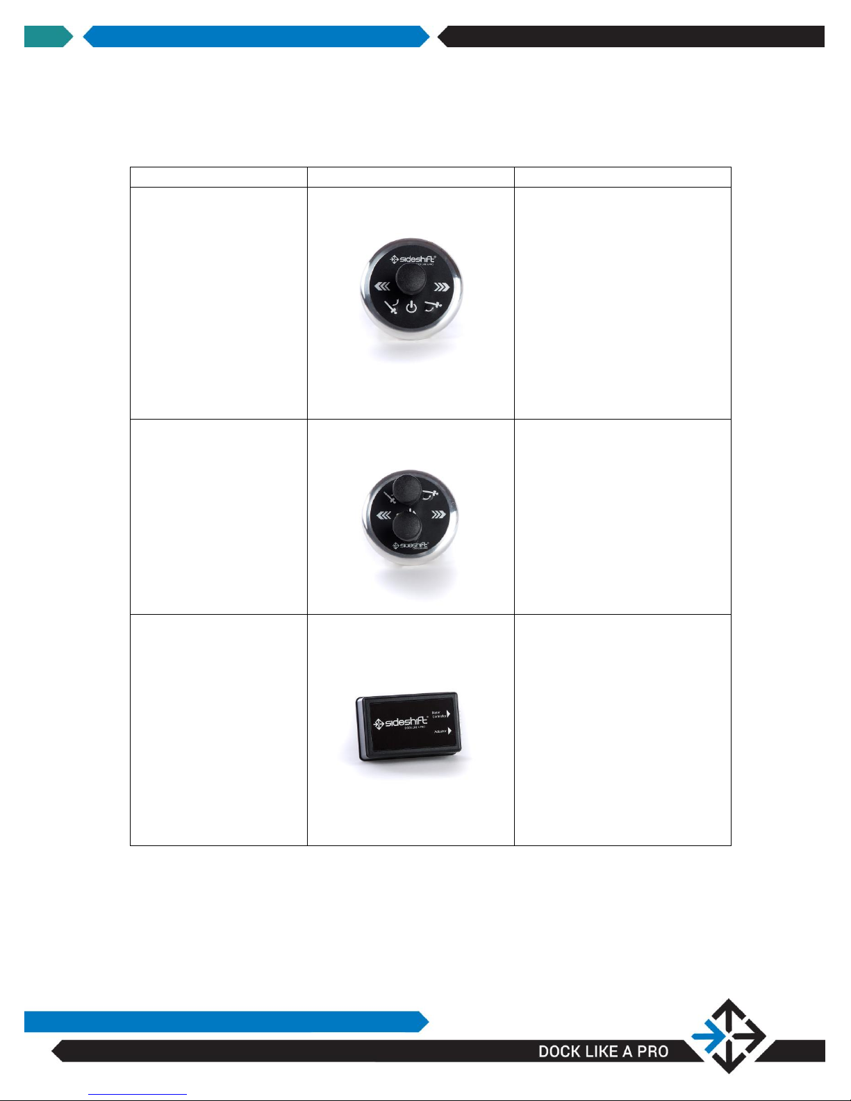
Single Wireless Joystick
Raise, lower and control
thruster.
Dual Wireless Joystick
Controls bow and stern thruster
on a single console for one-hand
operation
Wireless Control Module
Wireless receiver and control
interface between joystick and
motor controller.
SIDESHIFT INSTALLATION GUIDE V1.9
SIDESHIFT INSTALLATION GUIDE V1.9
4
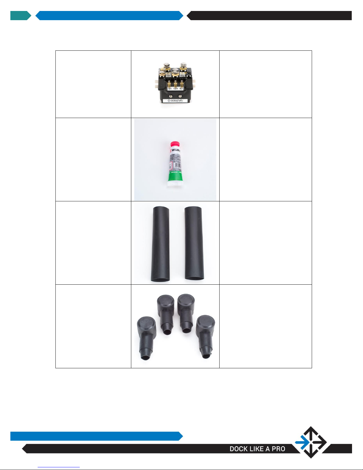
Motor Control Module
Relays commands from joystick,
delivering high current from
battery to motor.
Anti-seize
Prevents screw and bolt threads
from seizing, facilitating easier
assembly and disassembly.
Heat shrink tubes
(sufficient for all cables
attached to motor
controller. Cut to size)
Provides waterproofing for cable
at battery terminals.
Terminal protectors
Protects terminals from moisture
and prevents shorts.

SIDESHIFT INSTALLATION GUIDE V1.9
5
Compression terminals
Connects cables to motor
controller. Select size according
to wire gauge used.
Wireless Remote
Controls thruster remotely
Battery Switch
On/Off switch for thruster
batteries
Fuse/Digital Voltage
Indicator
Fuse protection and digital
voltage monitor
SIDESHIFT INSTALLATION GUIDE V1.9
6
INSTALLATION INSTRUCTIONS
Sideshift thrusters can be installed with the boat in water or on land, although landbased installation is easier.
Get an overview of the electrical installation procedures by viewing the installation
videos for our PT230 Pontoon Thruster and our SS/ST series Bow and Stern thruster
products on-line at sideshift.com/choose-sideshift/videos/videos/.
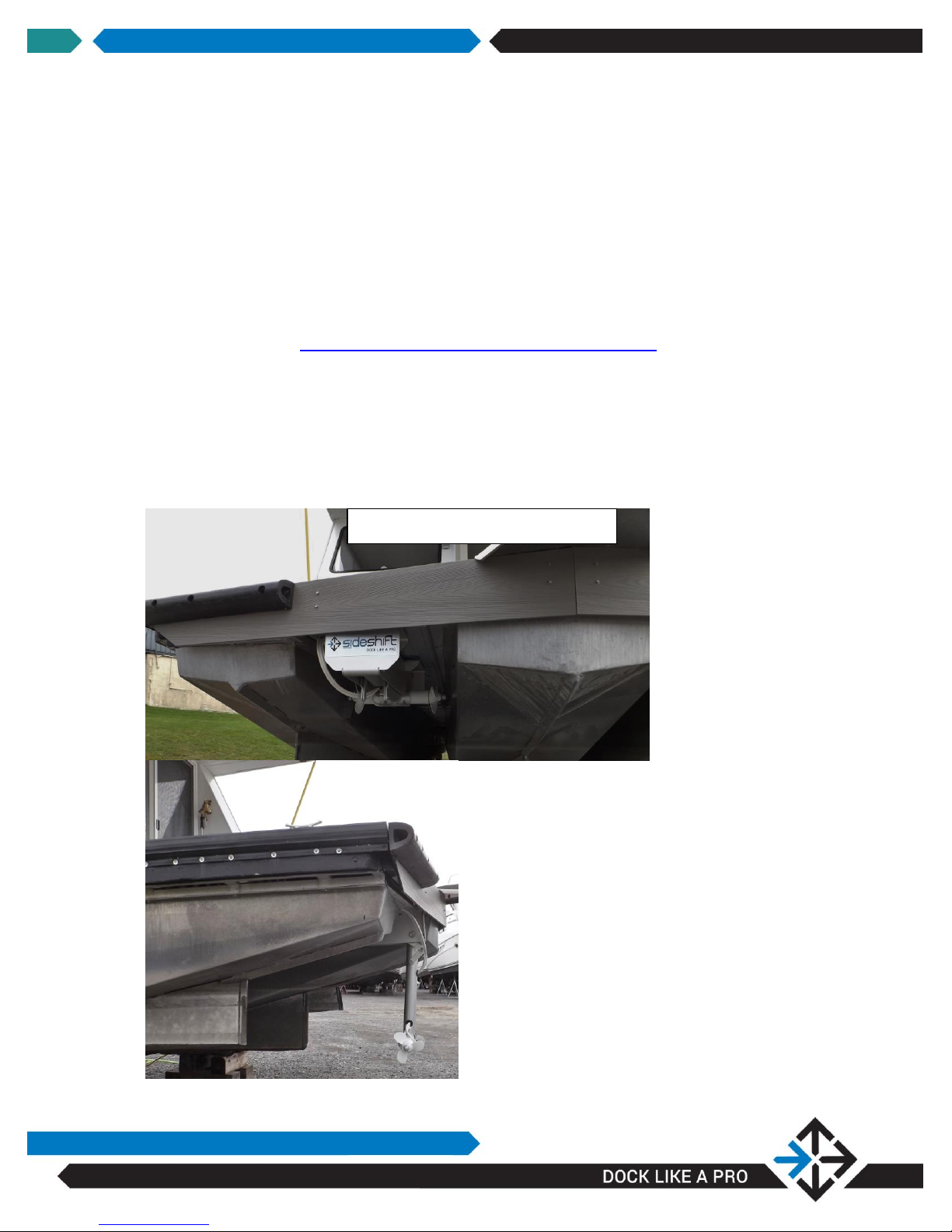
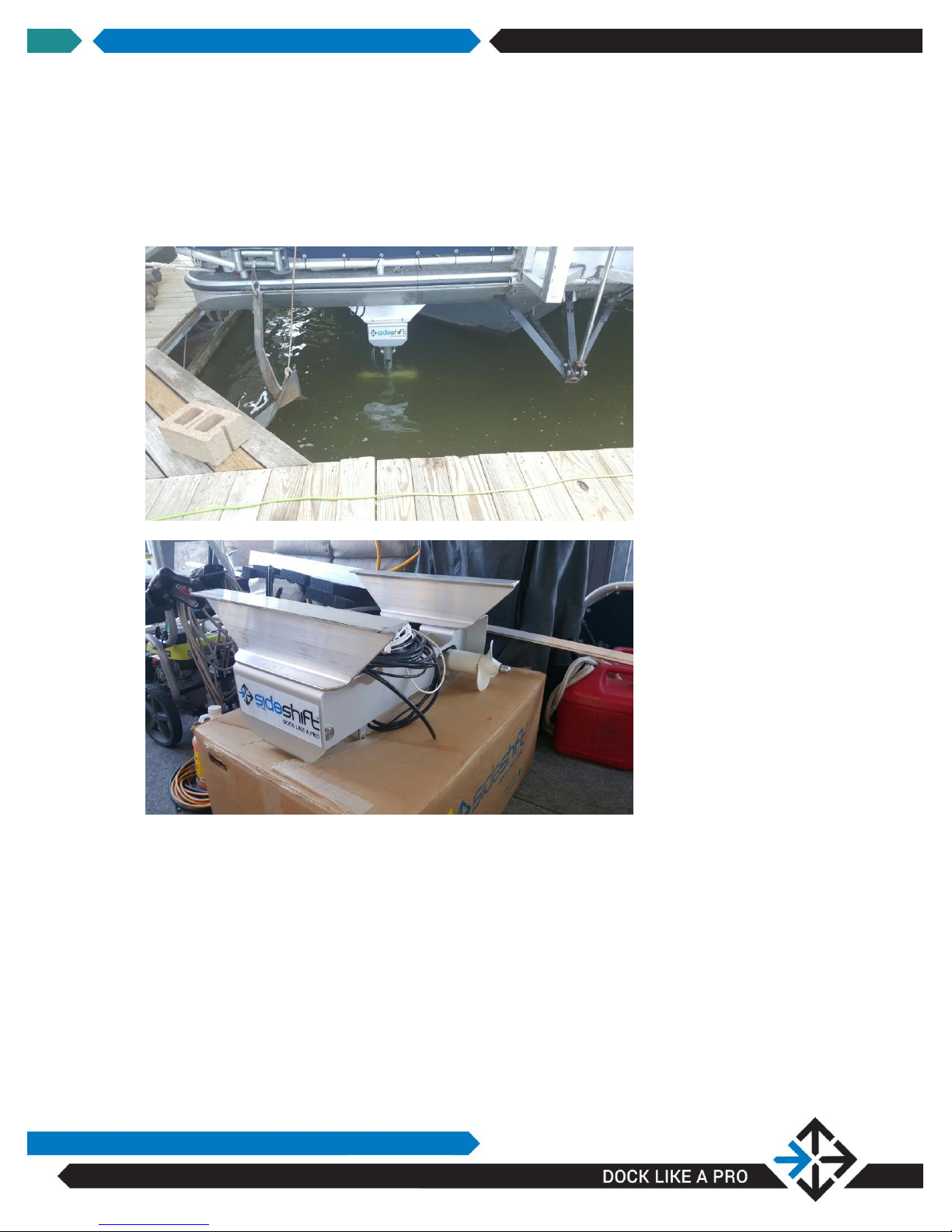
HB340/350 Bow Thruster Placement
The thruster is designed to be positioned on the underside bow of any pontoon-style
or flat-bottom style houseboat. Position the unit centrally or off-center, and as far
forward as possible for best performance.
Proper side clearance for good performance
SIDESHIFT INSTALLATION GUIDE V1.9
7
The thruster mounting surface can be a maximum of 24” from the water. If the
mounting surface is more than 24” above the water, a mounting bracket will need to
be created to provide a lower mounting surface. See example below:

SIDESHIFT INSTALLATION GUIDE V1.9
8
Step-By-Step Instructions:
STEP 1: DETERMINE A MOUNTING SURFACE WITH A MINIM U M OF
¼” ALUMINUM OR STEEL RIGID PLATING
RAILS TO FORM AN APPROPRIATE MOUNTING PL A T F O R M
The unit has pre-drilled mounting slots to accommodate 16” or 24”
centers. In some installations it will be necessary to drill through the
thruster mounting plate to fit centers other than 24”, or to attach to
mounting rails. Use a ¼” drill bit to drill the mounting plate.
NOTE: You will require a helper for Step 2
OR
ATTACH
STEP 2: POSITION THRUSTER AND ATTACH TO UNDERSIDE OF
DECK
Using a helper, position the thruster in place, and using the supplied self—
drilling/self-tapping 1 ¼” stainless hex-head mounting screws, apply a small amount
of supplied Loctite to the threads and drive the screws into the mounting surface at
the appropriate location. Pilot holes are not required. Two screws are required at
the front and two at the back of the unit.
 Loading...