

Page 1
Keep this
manual onboard !
SIDEPOWER
Thruster systems
D
Installations- und Bedienungsanleitung
Installation and user's manual
GB
Made in Norway
©
Sleipner Motor AS 2006
SLEIPNER MOTOR ASSLEIPNER MOTOR AS
SLEIPNER MOTOR ASSLEIPNER MOTOR AS
SLEIPNER MOTOR AS
P.O. Box 519
N-1612 Fredrikstad
Norway
Tel: +47 69 30 00 60
Fax:+47 69 30 00 70
www.side-power.com
sidepower@sleipner.no
SH 100/185 T
SP 220 HYD/SP 300 HYD
SP 550 HYD
Mechanical thruster installation only
Page 2

Inhalt
D
Hinweise zur Installation
Technische Daten ................................................................
3/4
Planungs- & Vorsichtshinweise ............................................. 5
Tunnelinstallation
Positionierung von Tunnel / Thruster ...................................... 6
Formgebung der Tunnelenden ............................................... 7
Optimaler Strömungsverlauf am Rumpf................................. 8
Mögliche Tunnelinstallation in Segelbooten .......................... 9
Installation bei Serienproduktion .......................................... 10
Tunnelinstallation bei Glasfiberrumpf ............................. 11/12
Thrusterinstallation
Getriebe und Motorhalterung ...................................... 13/14/15
Ölvorratsbehälter & Propeller ........................................... 16/17
Hydraulikmotor ............................................................ 18/19/20
Wartung & Service ................................................................. 21
Checkliste zur Kontrolle der Installation ............................... 22
Bedienungsanleitung
Benutzerhinweise .................................................................. 23
Benutzung von Sidepower Thrustern .................................... 23
Garantieerklärung ................................................................ 24
Ersatzteileliste & -zeichnung ............................................... 25
Service Partner .................................................................... 32
KONFORMITÄTSERKLÄRUNG
Das von Sleipner Motor AS
P.O. Box 519
N-1612 Fredrikstad, Norwegen
gelieferte Produkt sowie die standard Bedienelemente erfüllen die Gesundheits- und Sicherheitsanforderungen entsprechend der Verordnung 89/
336/EEC vom 23 Mai 1989, Ergänzung 92/31/
EEC und 93/68/EEC.
Installation instructions
Technical specifications ...................................................... 3/4
Planning & important precautions .......................................... 5
Tunnel installation
Positioning of the tunnel / thruster .......................................... 6
How to shape the tunnel ends ................................................ 7
How to prevent drag from tunnel installation .......................... 8
Possible tunnel installation in sailboats ................................ 9
Series production installation ............................................... 10
Tunnel installation in a GRP boat .................................... 11/12
Thruster installation
Gearhouse and motorbracket ..................................... 13/14/15
Oil tank & propeller .......................................................... 16/17
Hydraulic motor ........................................................... 18/19/20
Maintenance & service ........................................................... 21
Checklist for control of the installation .................................. 22
User's manual
Important user precautions .................................................... 23
How to use Sidepower thrusters .......................................... 23
Warranty statement ............................................................. 24
Spareparts list & drawing .................................................... 25
Service centres .................................................................... 32
Contents
GB
DECLARATION OF CONFORMITY
We, Sleipner Motor AS
P.O. Box 519
N-1612 Fredrikstad, Norway
declare that this product with accompanying
standard remote control systems complies with
the essential health and safety requirements
according to the Directive 89/336/EEC of 23
May 1989 amended by 92/31/EEC and
93/68/EEC.
SH100/185T - SP 220 HYD - SP 300 HYD - SP 550 HYD
2.4 - 2007
2
Page 3
Waterline
G
C
H
max
F
Technical specifications
GB
Port side Starboard side
SH100/185T S P 220HYD SP 300HYD SP 550HYD
Light duty thrust [kg] 100 220 300 550
Heavy duty thrust [kg] 80 200 270 500
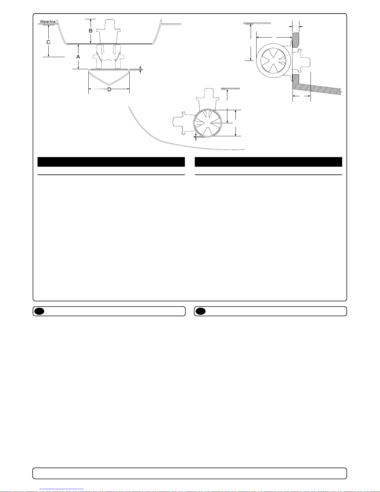
A [mm] 185 250 300 386
B [mm] 215 235 245 369
C min. [mm] 200 250 300 380
D [mm] 170 300 300 500
D recommended [mm] 340 600 600 750
Emin. [mm] 6 7 10 750
Emax. [mm] 8 10 13 10
F [mm] 165 195 195 298
G [mm] 256 360 420 540
H max. [mm]
Hydraulic power [kW] 8,1 18,7 23 42,3
Propeller output [kW] 6,5 15 18,4 33
Gear oil capacity [ml] --- 200 250 ---
Note: Emin.: wall thickness of a standard Sidepower tunnel
Emax.: maximum wall thickness when using other GRP,
steel or aluminium tunnels
Technische Daten
D
Motor: Hydraulic type (specifications above)
Gear house:
Seawater resistant bronze
Gears: Hardened precision gears
Lubrication: Oil bath from tank (gear oil EP 90)
Bearings: Angular contact ball bearing at propellershaft and
combination of ball bearing and needle bearing
at driveshaft.
Material: Seawater resistant bronze, protected with
zinc anode
Motor bracket: Seawaterresistant aluminium
Tunnel: Cross spun with rowing G.R.P tunnel
Steel & aluminum tunnels available at request.
Propellers: Symmetrical 4 blade kaplan propeller, fibreglass
reinforced composite.
SH100/185T: 5-blade skew " Q-PROP"
Control panel: Not supplied as standard
Safety
:
Flexible coupling between hydraulic-motor and
driveshaft protects gearsystem if propeller gets
jammed.
Motor: Hydraulisch (Technische Daten s.o.)
Getriebegeh.: Seewasserbeständige Bronze
Zahnräder: Gehärtete Präzisionsteile
Schmierung: Ölbad (Getriebeöl EP 90)
Lager: Winkelkontaktkugellager an der Propellerachse,
Kombination von Kugel- und Nadellager an der
Antriebsachse.
Material: Seewasserbeständige Bronze, durch Zink-
anoden vor Korrosion geschützt.
Motorhalterung: Seewasserbeständiges Aluminium
Tunnel: Glasfibertunnel (Kreuzgewebe)
Stahl- & Aluminiumtunnel auf Anfrage.
Propeller: Symmetrische, 4 flügelige Kaplanpropeller aus
Glasfiberverbundmaterial.
Steuerpanel: Nicht im Lieferumfang enthalten
Sicherheit
:
Elastische Kupplung zwischen hydraulischem
Motor und Getriebeachse als Schutz, wenn der
Propeller blockiert ist.
SH100/185T - SP 220 HYD - SP 300 HYD - SP 550 HYD
2.4 - 2007
3
SH100/185T S P 220HYD SP 300HYD SP 550HYD
Light duty thrust [lbs] 220 484 660 550
Heavy duty thrust [lbs] 176 440 594 500
A [in] 7,28 9,84 11,8 386
B [in] 8,50 9,30 9,60 369
C min. [in] 7,87 9,84 11,8 380
D [in] 6,70 11,8 11,8 500
D recommended [in] 13,4 23,6 23,6 29,5
Emin. [in] 0,24 0,28 0,39 0,39
Emax. [in] 0,31 0,39 0,51 0,59
F [mm] 6,5 7,75 7,75 11,75
G [mm] 10,1 14,2 16,5 21,3
H max. [mm]
Hydraulic power [Hp] 10,9 25,1 30,8 56,7
Propeller output [Hp] 8,7 20,1 24,7 44,3
Gear oil capacity [fl.oz] --- 6,763 8,45 ---
Note: Emin.: wall thickness of a standard Sidepower tunnel
Emax.: maximum wall thickness when using other GRP,
steel or aluminium tunnels
IMPERIALIMPERIAL
IMPERIALIMPERIAL
IMPERIAL
METRICMETRIC
METRICMETRIC
METRIC
8
8
8
8
8
8
8
8
E
C
Waterline
A
E
Page 4

SH100/185T - SP 220 HYD - SP 300 HYD - SP 550 HYD
2.4 - 2007
4
Requirements / Hydraulic hose connections to motor
Port A Drain port Port B
Motor type Port A Drain port Port B
U-6 1/2" BSP 1/4'' BSP 1/2" BSP
U-8 1/2" BSP 1/4'' BSP 1/2" BSP
U-10 3/4" BSP 1/4'' BSP 3/4" BSP
U-11 3/4" BSP 1/4'' BSP 3/4" BSP
U-14 3/4" BSP 1/4'' BSP 3/4" BSP
U-16 3/4" BSP 1/4'' BSP 3/4" BSP
U-19 3/4" BSP 1/4'' BSP 3/4" BSP
U-26 3/4" BSP 1/4" BSP* 3/4" BSP
U-29 3/4" BSP 1/4" BSP* 3/4" BSP
U-33 3/4" BSP 1/4" BSP* 3/4" BSP
U-37 3/4" BSP 1/4" BSP* 3/4" BSP
U-50 1" BSP 1/4" BSP* 1" BSP
P-42 1" 5000PSI SAE-7 518 1/4" BSP* 1" 5000PSI SAE-7 518
P-52 1 1/2" 5000PSI SAE-7 518 1/4" BSP* 1 1/2" 5000PSI SAE-7 518
Pro-40 ISO 6162 3/4'' 3/4'' UNF-16 ISO 6162 3/4''
Pro-60 ISO 6162 3/4'' 7/8'' UNF-14 ISO 6162 3/4''
* Drain port connector must not extend internally beyond 10.5 mm from end face.
(Must be installed)
Thruster Motor Flow Pressure Flow Pressure Flow Pressure
Ltr/min - bar 18,8 103 21,7 137 24,2 172
USG - PSI 5,0 1494 5,7 1987 6,4 2494
Ltr/min - bar 25,0 77 28,9 103 32,3 129
USG - PSI 6,6 1117 7,6 1494 8,5 1871
Ltr/min - bar 31,3 62 36,1 82 40,4 103
USG - PSI 8,3 899 9,5 1189 10,7 1494
Ltr/min - bar 19,1 217 21,3 272
USG - PSI 5,0 3147 5,6 3944
Ltr/min - bar 23,8 174 27,5 232 28,5 240
USG - PSI 6,3 2523 7,3 3364 7,5 3480
Ltr/min - bar 26,2 158 30,2 211 33,8 264
USG - PSI 6,9 2291 8,0 3060 8,9 3828
Ltr/min - bar 33,1 124 38,2 166 42,7 207
USG - PSI 8,7 1798 10,1 2407 11,3 3002
Ltr/min - bar 38,1 109 44,0 145 49,2 181
USG - PSI 10,1 1581 11,6 2103 13,0 2625
Ltr/min - bar 45,1 92 52,1 122 58,3 153
USG - PSI 11,9 1334 13,8 1769 15,4 2219
Ltr/min - bar 20,0 243 20,0 243
USG - PSI 5,3 3524 5,3 3524
Ltr/min - bar 22,0 221 24,6 276
USG - PSI 5,8 3205 6,5 4002
Ltr/min - bar 27,8 173 32,1 231 35,0 275
USG - PSI 7,3 2509 8,5 3350 9,2 3988
Ltr/min - bar 32,0 152 36,9 202 41,3 253
USG - PSI 8,5 2204 9,7 2929 10,9 3669
Ltr/min - bar 37,9 128 43,7 170 48,9 213
USG - PSI 10,0 1856 11,5 2465 12,9 3089
Ltr/min - bar 40,1 275 40,1 275
USG - PSI 10,6 3988 10,6 3988
Ltr/min - bar 45,4 255 46,9 272
USG - PSI 12,0 3698 12,4 3944
Ltr/min - bar 51,7 224 56,7 269
USG - PSI 13,7 3248 15,0 3901
Ltr/min - bar 58,1 200 65,4 253
USG - PSI 15,4 2900 17,3 3669
Ltr/min - bar 77,2 135 89,2 180 99,7 225
USG - PSI 20,4 1958 23,6 2610 26,3 3263
Ltr/min - bar 66,1 176 76,3 235 85,3 293
USG - PSI 17,5 2553 20,2 3408 22,5 4250
Ltr/min - bar 83,7 143 96,7 191 108,1 238
USG - PSI 22,1 2074 25,5 2770 28,6 3451
Ltr/min - bar 61,8 183 71,4 244 79,8 305
USG - PSI 16,3 2654 18,9 3538 21,1 4423
Ltr/min - bar 92,3 122 106,6 162 119,2 203
USG - PSI 24,4 1769 28,2 2349 31,5 2944
P
ro piston
60 ccm
SP550HYD
Ultra
26 ccm
319 kg
Ultra
29 ccm
352 kg
Ultra
33 ccm
396 kg
Ultra
37 ccm
Ultra
50 ccm
Pro piston
40 ccm
SP300HYD
Ul
tra
10 ccm
Ultra
19 ccm
P-42
42 ccm
P-52
52 ccm
Ultra
11 ccm
Ultra
14 ccm
Ultra
16 ccm
285 kg
SP220HYD
Ul
tra
8 ccm
165 kg
Ultra
10 ccm
Ul
tra
11 ccm
Ultra
19 ccm
Ultra
14 ccm
Ul
tra
16 ccm
SP 100 HYD
Ultra
6 ccm
Ul
tra
8 ccm
Ultra
10 ccm
495 kg
at 60% thrust at 80% thrust at 100% thrust
or max
thrust
180
418 kg
189 kg
225 kg
Page 5

Dieses Manual vor der Installation lesen, um ausreichende Kenntnisse über das Produkt zu erlangen.
Dieses Manual ist für Fachleute ausgelegt. Es sind daher nicht alle notwendigen Details für eine korrekte Installation enthalten.
Wenn die verfügbare Höhe begrenzt ist, kann der Sidepower in jedem Winkel bis zur Horizontalen eingebaut werden.
Mit dem Motor vorsichtig umgehen.
Die Installation innerhalb der vorgegebenen Maße halten. Es darf kein Teil des Systems aus dem Tunnel herausstehen.
Der Motor, Komponenten und Steuerleitungen müssen so installiert werden, daß sie stets trocken bleiben.
Auf Getriebegehäuse und Propeller Antifouling auftragen. PS ! Zinkanoden, Dichtungen, Propellerachse nicht bemalen.
Die Innenseite des Tunnels nicht mit Gelcoat / Topcoat o.ä. behandeln. Nur eine dünne Schicht Primer und zwei Schichten Antifouling
auftragen, da zwischen dem Tunnel und den Propellern nur ein geringer Zwischenraum besteht.
Bei Abnahmepflicht nach nationalen oder internationalen Bestimmungen, ist der Installateur für die Einhaltung dieser Bestim-
mungen verantwortlich. In diesem Leitfaden können zwangsläufig nicht alle weltweit geltenden Bestimmungen berücksichtigt werden.
Wird keine hydraulische Anlage von Sidepower installiert, muß folgendes sichergestellt werden:
Installieren Sie einen Ölfilter, um das Öl sauber zu halten.
Installieren Sie einen Ölkühler oder verwenden Sie einen Öltank, damit die maximale Öltemperatur zwischen 43 - 50
0
C liegt.
Die Anlage ist nur mit einem hydraulischen Motor ausgestattet.
Das restliche hydraulische System liegt in der Verantwortung des Installateurs/Monteurs und muß sich an die in diesem Manual
beschriebenen technischen Daten und Anforderungen halten, damit der Thruster nicht beschädigt wird.
Es sollte ein hydraulisches Ventil verwendet werden, daß Durchsatz und Druckwerte innerhalb, oder entsprechend einstellbar, der
Kapazität des verwendeten hydraulischen Motors besitzt.
Wir empfehlen unbedingt, ein Überdruckventil (10% - 15% über dem gewählten maximalen Druck im Steuerventil) zu installieren.
Dies schützt das System vor Beschädigung bei blockierten Propellern.
Es ist erforderlich, eine Vorrichtung zu installieren, damit die Schubrichtung nicht unmittelbar gewechselt werden kann, da dies zu
einem Getriebeschaden führen kann. Dies kann durch eine elektronische Zeitverzögerung im elektrischen Steuersystem oder die
Verwendung eines Ventils mit entsprechender Funktion berwerkstelligt werden. Die erforderliche Zeitverzögerung beträgt 1 Sekunde.
NB ! Bei falscher Installation von Tunnel, Thruster oder Kontrollpanel besteht keinerlei Garantieanspruch.
Planungs- und Vorsichtshinweise
D
Prior to installation, it is important that the installer reads this guide to ensure necessary acquaintance with this product.
This manual is intended to support educated / experienced staff and is therefore not sufficient in all details for the correct installation.
If the height in the room you are installing the Sidepower is limited, the Sidepower can be installed horizontally or at any angle in between.
The motor must be handled carefully.
Beware to keep installation within adviced measurements. No part of the propeller or gearhouse must be outside the tunnel.
The motor, its components or other joints and contol cables must be mounted so that they will keep dry at all times.
We advice to paint the gearhouse and propellers with antifouling. PS! Do not paint the zinc anodes, sealings or propellershafts.
Do not finish the inside of the tunnel with a layer of gelcoat / topcoat or similiar. It is only room for a thin layer of prime
r and two layers
of anti-fouling between the tunnel and the props.
When installed in boats approved or classified according to international or special national rules, the installer is responsible for
following the demands in accordance with these regulations / classification rules. The instructions in this guide can not be guaranteed
to comply with all different regulations / classification rules.
If no original Sidepower hydraulic system is installed, please ensure the following:
Install an oil filter to keep the oil clean.
Fit an oil cooler or use an oiltank so that the maximum oil temperature is 43 - 50 degrees Celcius.
This thruster is supplied with a hydraulic motor only.
The rest of the hydraulic system is the responsibility of the fitter/installer and must be within the limitations that are described in this
manual so that it does not damage the thruster.
It is very important to use a hydraulic valve that has flow and pressure limits that are either set within or can be adjusted to be within the
limits of the thrusters capability.
We also strongly recommend that a shock valve are fitted and set to 10% - 15% above the chosen maximum pressure set in the valve.
This will prevent that the system is dammaged if the propellers are blocked by any reason.
It is also required that a device is installed to ensure that the drive direction can not be suddenly changed, as this can seriously
dammage the gearhouse. This can be done by adding an electronic time lapse / delay safety on the electric control system or by using a
valve that has this type of protection built in. The required time delay is 1 second.
NB ! Faulty installation of the tunnel, thruster or panel will render all warranty given by Sleipner Motor AS void.
Planning and important precautions
GB
SH100/185T - SP 220 HYD - SP 300 HYD - SP 550 HYD
2.4 - 2007
5
Page 6
SH100/185T - SP 220 HYD - SP 300 HYD - SP 550 HYD
2.4 - 2007
6
Tunnelplazierung soweit vorne wie möglich (Fig. 1)
Um einen möglichst großen Abstand vom Drehpunkt des Schiffes zu
erreichen, ist der Sidepower möglichst weit vorne einzubauen.
Eine Vergrößerung des Abstandes vom Drehpunkt des Schiffes
hat eine direkte Auswirkung auf die verfügbare Schubkraft.
Beispiel
:
A: 100kg Schubkraft x 11m = 1100kgm zum Wenden des Bootes
B: 100kg Schubkraft x 10m = 1000kgm zum Wenden des Bootes
In Beispiel A stehen damit 10% mehr Schubkraft zur Verfügung.
Den Tunnel so tief wie möglich positionieren (Fig. 2)
Den Tunnel aus zwei Gründen so tief wie möglich positionieren:
1. Damit nicht Luft mitangesaugt wird, die die Schubkraft
vollständig herabsetzt.
2. Um einen möglichst hohen Wasserdruck zu erhalten, um die
maximale Effizienz des Propellers erreichen.
Die Oberkante des Tunnels muß mind. einen halben Tunneldurchmesser unterhalb der Wasserlinie liegen. Dieser Wert ist ein
absolutes Minimum. Besser ist ein Wert von ca. 3/4 des
Tunneldurchmessers (☺). Optimal ist eine Abstand von 1/1 x
Tunneldurchmesser (☺☺) zur Wasserlinie.
Liegt die Oberkante des Tunnels 30-35cm* / 1Fuß unterhalb der
Wasserlinie, können andere Faktoren berücksichtigt werden.
Optimale Tunnellänge
Bei einem zu langem Tunnel reduziert der Reibungsverlust die
Wassergeschwindigkeit und damit die Schubkraft.
Bei einem zu kurzem Tunnel (häufig im unteren Bereich des
Tunnels) können Kavitationsprobleme entstehen, da sich das
Wasser nicht gerade auszurichten kann (Fig. 3/4). Diese Kavitation
ist leistungsreduzierend und kann starken Lärm verursachen.
Die optim. Tunnellänge ist das 2-4 fache des Tunneldurchmessers.
Tunnellängen von mehr als dem 6-7 fachen des Tunneldurchmessers sollten vermieden werden, da dadurch die Leistung
reduziert wird.
Positionierung von Tunnel / Thruster
D
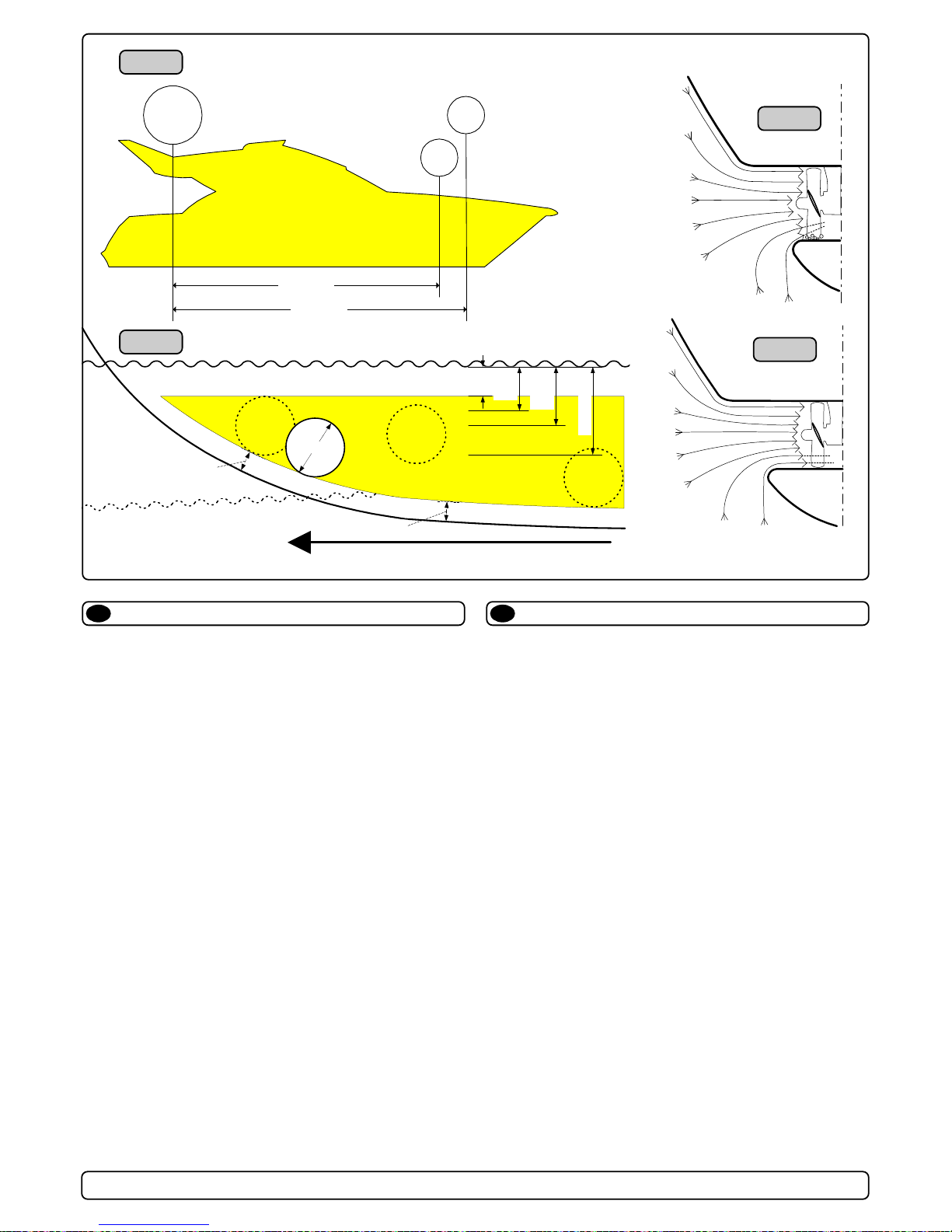
The Thruster should be as far forward as possible (Fig. 1)
Because of the leverage effect around the boats pivot point, it is very
important for the thrusters actual effect in the boat to get it as far forward as possible. The relative distance change from the boats pivot
point to the thruster
will be the change of actual thrust for the boat.
Example
:
A: 100kg thrust x 11m leverage = 1100kgm torque to rot. the boat
B: 100kg thrust x 10m leverage = 1000kgm torque to rot. the boat
In position A you will get 10% more thrust to turn the boat around.
The thruster should be placed as deep as possible (Fig. 2)
The tunnel should be placed as deep as possible for two reasons:
1. So that it does not suck down air from the surface which will
destroy the thrust completely.
2. To get as high as possible a water pressure to get maximum
efficiency from the propeller.
Generally the top of the tunnel should be a minimum of 1/2 x the
tunnel diameter below the waterline. This is an absolute minimum
and we recommend that it is at least 3/4 x tunnel diameter (☺)
below the waterine. A really good distance is about 1/1 x tunnel
diameter (☺☺) below the waterline.
When you get the top of the tunnel 30-35 cm* / 1 feet below the
surface, other factors should be considered more important, i.e.
moving the thruster further forward.
Optimal tunnel length
If the tunnel gets to long, the friction inside will reduce the water
speed and thereby the thrust.
If the tunnel gets to short (normally only in the bottom section of the
tunnel) you can get cavitation problems as the water will not have
had time to “straigthen” itself before reaching the propeller (Fig. 3/4).
This caviation will reduce performance as well as creating a lot of
noise.
The optimal tunnel length is 2 to 4 x tunnel diameter and you
should avoid tunnels longer than 6 to 7 times the tunnel diameter
as the performance reduction is then clearly noticeable.
Positioning of the tunnel / thruster
GB
A = 11,0m
B = 10,0m
A
B
Pivot
point
m
i
n
.
1
/
3
Ø
Ø
m
i
n
.
1
/
3
Ø
3/4Ø
☺
1/1 Ø
☺ ☺
30 - 35 cm*
min.
1/2Ø
Fig. 1
Fig. 2
Fig. 3
Fig. 4
Page 7
Formgebung der Tunnelenden
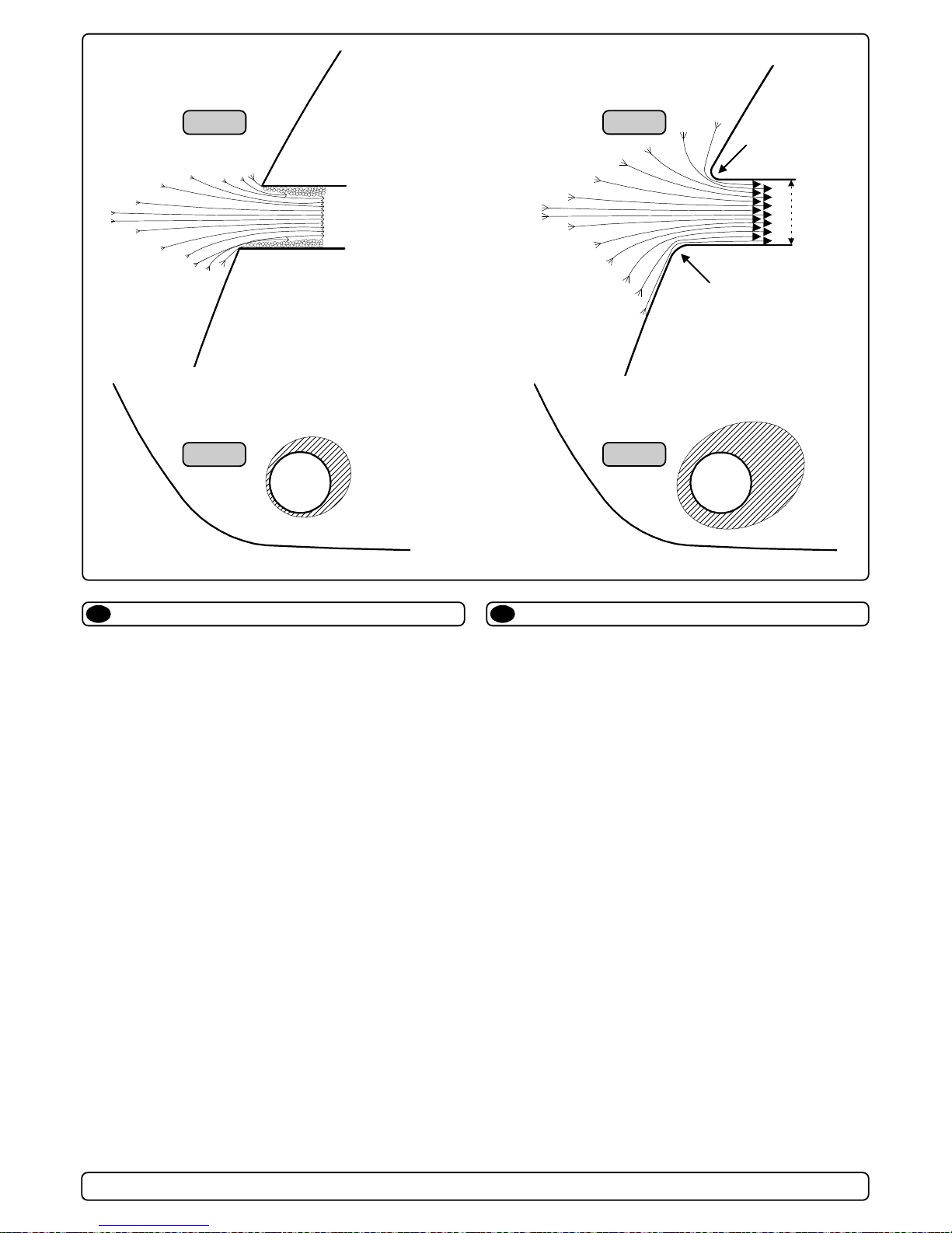
Rounded tunnel ends will maximize thrust and minimize
noise.
We recommend to round the tunnel connection to the hull-side as
much as possible.
The optimum rounding has a radius of 10% of the tunnels diameter.
Important advantages over sharp tunnel to hull connections are:
1. The rounded tunnel end will prevent creation of turbulence /
cavitation that will come from a sharp tunnel end when water
passes by fast, thereby preventing a double negative impact on
the thrust and noise level (Fig. 1&2).
- The turbulence / cavitation blocks the outer area of the tunnel
and thereby reduces the effective tunnel diameter and thrust.
- The turbulence / cavitation hits the propeller and thereby
reduce the propellers performance and creates noise.
2. The curved tunnel end makes the thruster take water also from
along the hull-side, creating a vacuum that will suck the boat
sideways and thereby give additional thrust (Fig. 3&4).
With a sharp tunnel end, the thruster will be unable to take water
from along the hull-side, and you will not get the desired vacuum
and additional thrust.
This "free" additional thrust can in optimal installations be as
much as 30 - 40% of the total thrust.
NB! A Sidepower thruster propeller does not cavitate at working
speed so that all cavitation and cavitation noise in the tunnel
will be caused by the tunnel installation.
NB! Even if it is not possible to make the perfect rounding, it is
very important to round the tunnel end as much as possible.
A angled tunnel to hull connection will also do much of the
same job as a rounded connection (see page 20, Fig. 1b&1d).
Abgerundete Tunnelenden erhöhen die Schubkraft und
reduzieren das Geräuschniveau.
Der Bereich Tunnelende / Außenseite des Rumpfes ist soweit
möglich abzurunden. Der optimale Wert für den Radius dieser
Rundung beträgt 10% des Tunneldurchmessers.
Vorteile gegenüber einer scharfen Tunnel / Rumpfverbindung sind:
1. Abgerundete Tunnelenden verhindern Turbulenzen / Kavitation,
wie sie an scharfenkantigen Tunnelenden auftreten. Damit
werden zwei negative Auswirkungen auf Schubkraft und
Geräuschentwicklung vermieden (Fig. 1 & 2).
- Turbulenz / Kavitation blockieren den äußeren Tunnelbereich.
Dadurch werden effektiver Tunneldurchmesser und Schubkraft reduziert.
- Die Turbulenz / Kavitation trifft auf den Propeller und reduziert
dessen Effektivität und führt zu zusätzl. Geräuschentwicklung.
2. Abrundungen ermöglichen, daß Wasser entlang der Rumpfaußenseite angesaugt werden kann. Dadurch entsteht ein
Vakuum ("zusätzliche" Schubkraft"), das das Schiff seitwärts
bewegt (Fig. 3&4). Bei scharfkantigen Enden kann kein Wasser
entlang der Rumpfaußenseite angesaugt werden, wodurch das
benötigte Vakuum nicht zustande kommt.
Diese Schubkraft kann bei optimaler Installation bis zu 30-40%
der absoluten Schubkraft betragen.
NB ! Sidepower Propeller sind so ausgelegt, daß sie nicht
kavitieren, sodaß die Geräuschentwicklung aufgrund von
Kavitation durch die Tunnelinstallation bedingt ist.
NB ! Ist eine optimale Abrundung nicht möglich, so sind die
Tunnelenden soweit möglich abzurunden. Angeschrägte
Tunnel / Rumpfverbindungen sind zu einem gewissen Grad
ebenfalls mit ähnlich positiven Auswirkungen wie eine
Abrundung verbunden (siehe Seite 20, Fig. 1b&1d).
Tunnel ends
GB D
SH100/185T - SP 220 HYD - SP 300 HYD - SP 550 HYD
2.4 - 2007
7
☺☺
☺☺
☺
Fig. 2
Fig. 4
Fig. 1
Fig. 3
R = 0,1 x D (10%)
R = 0,1 x D (10%)
D
Page 8
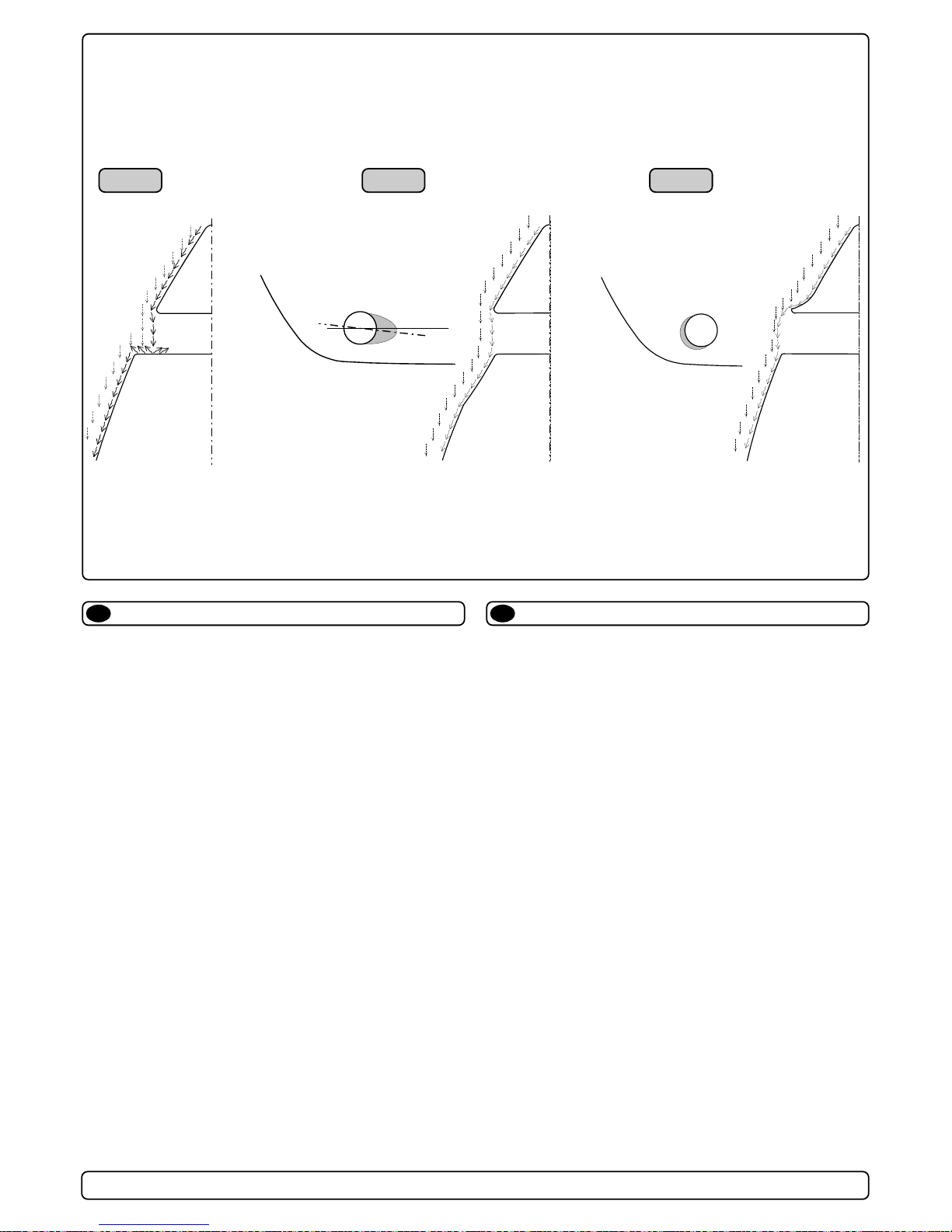
Segelboote und sehr schnelle Booten können gelegentlich durch
auf die rückseitige Fläche des Tunnels auftreffendes Wasser
gebremst werden (Fig. 1).
Dies kann dazu führen, daß sich der Thruster durch den permanenten Wasserdurchfluß hörbar passiv zu drehen beginnt.
Das Problem kann je nach Möglichkeit auf zwei Arten beseitigt
werden.
1. Der störende Effekt wird am deutlichsten reduziert, indem man
im Rumpfbereich hinter dem Tunnel eine Aussparung vornimmt.
Dadurch werden Auftreffläche und störender Effekt eliminiert
(Fig. 2).
Tiefe und Form dieser Aussparung hängen vom Boot ab.
Die Innenseite des Tunnels sollte von vorne prinzipiell nicht
sichtbar sein.
Der mögliche Winkel der Aussparung hängt meist von der
Rumpfform ab. Bedingt durch die Wasserströmung in diesem
Bereich sollte dieser Winkel leicht nach unten gerichtet sein.
2. Der Geschwindigkeitsverlust kann speziell bei schnellen Booten
durch einen Abweiser bzw. Spoiler vor dem Tunnel deutlich
reduziert werden.
Das Wasser wird so beeinflußt, daß es größtenteils an der
frontalen Fläche vorbei geleitet wird (Fig. 3).
Form und Größe des Abweisers hängen von der Rumpfform ab.
Prinzipiell sollte auch hier die Innenseite des Tunnels von vorne
nicht sichtbar, sondern durch den Abweiser verdeckt sein.
Dieser läßt sich einfach realisieren, indem man den Tunnel ein
Stück aus dem Rumpf herausstehen läßt und darauf einen
geschwungenen Abweiser / Spoiler formt.
Die Tunnelenden sind zur vollen Leistung und minimalen
Geräuschentwicklung des Thrusters weitgehend abzurunden.
Weitere Informationen siehe Seite 6.
Optimaler Strömungsverlauf am Rumpf
D
A possible problem in sailboats or fast powerboats, is that they get
a drag from the back face of the tunnel, as this becomes a “flat”
area facing the water flow (Fig. 1).
This can also create problems with the thruster spinning (passive)
and making noise while sailing or driving the boat with water being
pushed through the tunnel at high speed.
This can be solved in two different ways, depending on what is
possible or more easy to do.
1.
The best solution which normally reduces the drag most, is to
make a recess in the hull at the back of the tunnel.
Thereby the back face is gone and about all the drag (Fig. 2).
The depth and shape of this recess will depend on the boat.
Basically you should not see the back face of the tunnel when
standing directly in front of the tunnel at the angle of the boats
centreline.
The angle up or down backwards of the insert in the hull,
depends on the hullshape, but normally it is angled slightly
down because of the waterflow on this area of the hull.
2. The drag will also be reduced a lot, especially in fast power
boats, by making a deflector / spoiler in front of the tunnel.
This will push the waterflow out from the hull so that most of it
passes by the back face of the tunnel (Fig. 3).
The shape and size of this deflector will depend on the hull
shape. Basically you should not see the back face of the tunnel
when standing directly in front of the tunnel at the angle of the
boats centreline.
The easiest way of making this is to let a part of the tunnel stick
out in the lower forward area of the hole, and use this as a
support to mould a soft curve / spoiler shape.
Remember to still round the tunnel ends as much as possible to
get optimum thruster performance and minimum noise.
More information on how to practially do this on pages 6.
☺☺
☺☺
☺
☺☺
☺☺
☺
Prevent drag from tunnel
Fig. 2Fig. 1 Fig. 3
GB
SH100/185T - SP 220 HYD - SP 300 HYD - SP 550 HYD
2.4 - 2007
8
Page 9

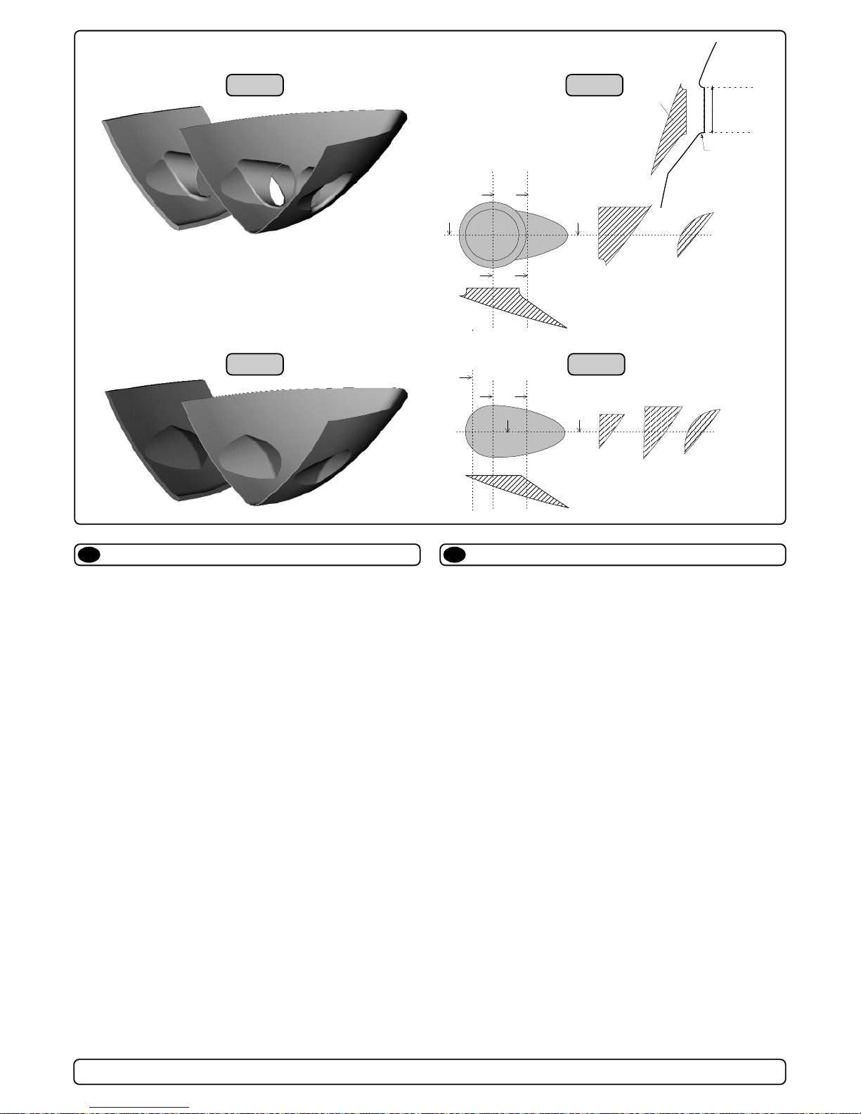
Segelboote weisen häufig einen Rumpf in Rennform auf, was
einen sehr flachen Rumpf im Bugbereich bedeutet. Es ist daher
schwierig oder fast unmöglich, den Tunnel an der gewünschten
(effektivsten) Stelle, also möglichst weit vorne im Bug zu plazieren
(Fig. 1).
Trotzdem ist es vielfach möglich unter diesen Bedingungen eine
Bugschraube einzubauen, auch wenn der Tunnel damit nicht völlig
vom ursprünglichen Rumpf umgeben ist.
Der Tunnel wird zur Hälfte in den bestehenden Rumpf integriert,
die andere Hälfte geht über diesen hinaus. Der Tunnel muß nur
noch verstärkt und strömungsgünstig abgerundet werden.
Dies erlaubt eine Installation in geeigneter Position bei Nutzung
der Zuverlässigkeits- und Platzvorteile einer Tunnelschraube.
Diese Installationsart wird von einigen der weltweit führenden
Segelboothersteller verwendet und führt meistens nur zu einem
äußerst geringen bzw. gar keinem Geschwindigkeitsverlust.
Diese Bauweise ist auch für Barkassen (z.B. Flußboote) mit
flachem Bug geeignet, um einen zu langen Tunnel und große
ovale Tunnelöffnungen im Rumpf zu vermeiden.
Installation in Segelbooten
D
Many sailboats have a racing type hull which means that it is very
flat bottomed and has a very shallow draft in the bow section. It is
thereby very difficult not to say impossible to fit a tunnel thruster the
usual way, at least as far forward in the hull as a thruster should be
(Fig. 1).
However, it is possible to install a tunnel thruster in most sailboats,
even when the hull does not directly support the fitting of a tunnel.
This is done by fitting the tunnel halfway into and halfway underneath the exisiting hull and then strengthen it and smoothening the
waterflow by moulding a bulb around / underneath the tunnel.
This will allow installation in good position on the boat, maintaining
the reliability and space advantages of a tunnel thruster.
This installation is being used by some of the worlds absolute
largest sailboat builders, and have been proven to give little to no
speed loss for normal cruising.
This can also be a good installation method for flat bottomed
barges to avoid extremely long tunnels and huge oval tunnel
openings in the hull.
Tunnel installation in sailboats
GB
SH100/185T - SP 220 HYD - SP 300 HYD - SP 550 HYD
2.4 - 2007
9
Fig. 1
Min
☺☺
☺☺
☺
Pos. B
Pos. A
☺☺
☺☺
☺
Page 10
Hersteller die Thruster als Standard oder Modelle mit Bug- bzw.
Heckschrauben anbieten, haben die Möglichkeit einer kosten- und
zeitsparenden Tunnelinstallation (Fig. 1), die trotzdem maximale
Schubkraft bei minimaler Geräuschentwicklung erlaubt.
Durch eine Ausformung in der Rumpfform (fest oder als Einsatz),
kann der Tunnel später auf einfache Art und Weise installiert
werden (Fig. 2).
Die Ausformung / Einsätze sind relativ einfach herzustellen, sollten
aber nur mit der Form verschraubt werden, da sie mit dem Rumpf
aus der Form genommen werden müssen. Dadurch können auch
Rümpfe ohne Tunnelvorbereitung hergestellt werden. (Da viele
Kunden nachträglich einen Thruster einbauen, liefern einige
Hersteller bereits alle Einheiten mit fertiger Tunnelvorbereitung.)
Durch die gerade Oberfläche zur Aufnahme des Tunnels werden
Installationszeit und -kosten reduziert da:
- sich das kreisförmige Loch sehr einfach und schnell aus dem
Rumpf ausschneiden läßt
- der Tunnel sich auf der Innenseite einfacher mit dem Rumpf
verbinden läßt
- die Tunnellänge reduziert wird
Der Einsatz kann auch fester Bestandteil der Form sein, allerdings
müssen die Tunnelenden dann nachträglich abgerundet werden,
um den Rumpf aus der Form zu lösen zu können (Fig. 3&4).
Installation bei Serienproduktion
D
Boat builders having thrusters as standard, or delivering a large
portion of one or more models with thrusters, have the opportunity
to make a perfect tunnel installation, while saving both time and
money on each installation (Fig. 1).
The solution is to make an insert / plug in the hull mould, which
prepares the hull for an easy tunnel installation with features for
maximum thrust and minimal drag (Fig. 2).
This insert / plug in the mould is not very difficult to make, and as it
will have to be a "bolt on" in the mould in order to get the boat out,
you can still make boats without this hull feature. (Some boat
builders have this in the hull also on boats that are delivered
without a thruster as they know many people will fit this later)
By having a flat surface to fit the tunnel to, the installation time and
cost for the tunnel will also be reduced as:
-
it is very easy and fast to cut the now circular hole for the tunnel
-
it is easier to mould inside all around the tunnel
- you save tunnel length
The plug in the mould can also be made so that it can be a fixed
part of the mould, but the rounded end option must then be made
later to get the hull out of the mould (Fig. 3&4).
Series production installation
Fig. 1
Fig. 3
Fig. 2
Fig. 4
GB
a1
b
a1
a2
a2
b
a1
a2
b
D
Radius
=
D x 0,1
A
d
d
c1
c2
c2 c3
d
c3
c1
SH100/185T - SP 220 HYD - SP 300 HYD - SP 550 HYD
2.4 - 2007
10
Page 11

Wir empfehlen, die Glasfiberarbeiten von einem Fachmann ausführen zu lassen. Dieses Handbuch beinhaltet nicht alle
notwen-digen Details für diese Arbeit. Der Installateur trägt die
volle Verantwortung für eine sachgemäße Installation des
Tunnels.
Zunächst ist die Position des Tunnels aufgrund der vorangegangenen Informationen und der Maße des einzubauenden Thrusters zu
bestimmen.
Das Zentrum auf beiden Seiten des Tunnels anreißen. Dort jeweils
ein horizontales Loch (ø 6mm) bohren (Fig. 1).
Durch beide Löcher eine Stahlstange (ø 5mm) führen und die
Tunnelöffnung anzeichnen (Außendurchmesser des Tunnels).
Diese Fläche mit einer Stichsäge ausschneiden (Fig. 2).
Den Rumpf auf der Innenseite 12cm um das Tunnelloch frei von
Gelcoat und Polyester machen, bis Fiberglas sichtbar wird (Fig. 3).
Den Tunnel einsetzen und die Schnittlinie mit dem Rumpf anzeichnen (Fig. 4). Wird ein Abweiser / Spoiler benötigt, lassen Sie den
Tunnel etwas aus dem Rumpf stehen (Vorder- und Unterseite des
Tunnels), um einen Grundträger zu erhalten (siehe Seite 18, Fig. 2).
Die Tunnelenden auf die gewünschte Form abschneiden und die
Enden leicht anschleifen. Danach mit Aceton o.ä. dort reinigen, wo
Fiberglas aufgetragen werden soll.
NB ! Nicht im Bereich des Thrusters laminieren.
Den Tunnel im Rumpfinneren einlaminieren. Dazu mind. 8 Schichten zu je 300 g Glasfiber und Ployesterharz verwenden; vorzugsweise verschiedene Matten und Gewebearten (siehe Seite 18, Fig.
1). Sollen die Tunnelenden später den optimalen 10% Radius
aufweisen, müssen gelegentlich zusätzliche Schichten aufgetragen werden um eine ausreichende Rumpfstärke zu erhalten.
NB ! Jede Öffnung zwischen Tunnel und Rumpf muß vollständig
mit Poyesterharz/Glasfiber ausgefüllt sein. An schlecht zugänglichen Stellen, wo normale Schichten nicht möglich sind, muß zumindest eine Polyesterharz / Glasfiber Mischung eingefüllt werden.
Tunnelinstallation
D
We recomend that a professional does the fibreglass fitting of
the tunnel. These instructions are only general, and do not
explain i
n any way the details of fibreglass work. Problems
caused by faulty installation of the tunnel, are the installers full
responsibility.
Find the position in the boat considering the information given
earlier in this manual and the applicable measurements for the
thruster model you are installing.
Mark the centre of the tunnel on both sides. Drill a 6mm hole
horizontally in these marks (Fig. 1) .
Bend a ø 5mm steel bar as shown with the "tip" bent back at the
tunnel radius and mark the circle for the tunnel opening (outside
diameter of the tunnel). Cut the hole with a jigsaw (Fig. 2).
Grind off the gelcoat and polyester so that you are down in the
“real fibreglass” in an area of 12cm around the hole both inside and
outside in the hull to cast the tunnel to the hull (Fig. 3).
Insert the tunnel and mark its shape to fit the hull (Fig. 4). If you are
installing with a deflector/spoiler, leave a part or the tunnel of the
front- and underside of the tunnel to have a base for this (see page
12, Fig. 2). Cut the tunnel ends to the desired shape and lightly
sand its surface and clean with aceton or similar where you are
going to apply fibreglass.
NB! Do not cast/glass on the area were the thruster will be placed.
Then cast the tunnel to the inside of the hull, use at least 8 layers of
300 g glass and resin, preferrably alternating mat and rowing types
of fibreglass (see page 18, Fig. 1). If you are rounding the tunnel
ends to the perfect 10% radius you may in some cases have to
make further layers inside to preserve the desired hull thickness.
NB ! Make sure that any gap between the tunell and the hull are
completely filled with resin/fibreglass. In areas where you can not
access to make normal layers of resin/fibreglass, a resin/ fibreglass
mixture must be filled in that area.
R
D
Tunnel installation
Fig. 1
Fig. 3 Fig. 4
Fig. 2
GB
SH100/185T - SP 220 HYD - SP 300 HYD - SP 550 HYD
2.4 - 2007
11
Page 12

Runden Sie die Kanten mit einem Radius (10% des Tunneldurchmessers) ab (Fig. 1a) oder machen Sie eine Schräge mit einer
Länge von 10-15% des Tunneldurchmessers (Fig. 1c). Ist beides
nicht möglich, sind die Tunnelenden soweit möglich abzurunden.
Auf der Außenseite zusätzlich zwei Schichten im Bereich Rumpf /
Tunnel auf einer Fläche von 6-8cm auftragen (Fig. 1c&1d).
Danach auf den äußeren, angeschliffenen oder laminierten Flächen
Gelcoat/Topcoat/Epoxy zur wasserdichten Versiegelung aufbringen.
NB ! Original Sidepower tunnel sind in ausgeliefertem
Zustand absolut wasserdicht.
Wird nicht eine spezielle Farbe gewünscht, so sind keinerlei
Gelcoat, Topcoat oder Primer nötig, die ansonsten zur
Wasserdichtigkeit benötigt werden.
Empfehlenswert ist ein leichtes anschleifen und aufbringen einer
Primerschicht zur besseren Haftung des Antifouling.
Original Sidepowertunnel sind auch ohne Behandlung absolut
wasserdicht.
Auf laminierten oder angeschliffenen Flächen ist Gelcoat / Topcoat /
Epoxy und Primer aufzubringen, da diese Bereiche ohne
entsprechende Behandlung nicht wasserdicht sind.
PS ! Im Bereich der Motorhalterung darf nicht laminiert wer-
den, da dies zu Ungenauigkeiten bei der Montage und
damit einem möglichen Getriebeschaden führen kann.
Tunnelinstallation
D
Soften the edges with a radius of 10% of the tunnel diameter (Fig.
1a) or make a slope with a length of 10 - 15% of the tunnel diameter (Fig. 1c). If this is not possible, atleast round the tunnel end as
much as possible.
We advice to also cast two layers on the outside of the tunnel/ hull
for an area 6-8cm (Fig. 1c&1d).
You must apply gelcoat/topcoat/epoxy on the areas outside where
you have grounded or moulded to again make these waterproof.
NB
!
All original Sidepower tunnels are fully waterproof when
they are delivered.
This means that unless you want, because of special reasons, to
have another colour on it, you do not have to apply Gelcoat/Topcoat
or the several layers of primer that is necessary on the boats' hull
to make it waterresistant.
Sand it very lightly and apply one layer of primer to make the
antifouling sit.
The original Sidepower tube itself is fully waterresistant without
treatment exceptin the areas where you have bonded it to the hull.
Apply gelcoat/topcoat/epoxy paint and primer on the areas where
you have grounded or moulded as these areas give the water
access to the hull which normally is not waterproof without these
applications outside.
PS ! Avoid all casting where the motor-bracket is to be
placed, as this will cause misfit and possible failure of
the gearhouse.
Tunnel installation
GB
SH100/185T - SP 220 HYD - SP 300 HYD - SP 550 HYD
2.4 - 2007
12
R = D x 0,1
R = D x 0,1
D
x
0
,
1
-
0
,
1
5
D
x
0
,
1
-
0
,
1
5
D
Fig. 1a
Fig. 1
Fig. 1b
Fig. 2
Fig. 3
Fig. 1d
Fig. 1c
Page 13

1. Die Mittellinie von Tunnel und Boot markieren.
Damit Schub-
richtung und Kontrollpanel übereinstimmen,
das Getriebegehäuse so einbauen, daß der Verschluß des Getriebegehäuses
(der verschraubte Verschluß hinter einem der beiden Propeller) Richtung Steuerbord zeigt.
2. Die Löcher mit der Dichtung (7) markieren. Maße überprüfen!
Den Thruster schiffssmittig plazieren (Fig. 1). Da der Abstand
zwischen Propellern und Tunnel wegen größtmöglicher
Performance minimal konstruiert ist, müssen für eine präzise
Installation alle Löcher auf der Tunnelmittellinie liegen.
3. Im Bereich der Motorhalterung darf kein Laminat auf dem
Tunnel sein, da dies zu einem Getriebeschaden führen kann.
Liegt die Motorhalterung nicht eben auf dem Tunnel auf, so
sind sämtliche Unebenheiten in diesem Bereich abzuschleifen.
4. Bohren Sie das Zentrumsloch (ø 32 mm) und dann die beiden
Schraubenlöcher (ø 9 mm).
5. Das Getriebegehäuse unter Verwendung der Dichtung in den
Tunnel einpassen. Den Propeller auf die Achse stecken; dieser
muß sich frei bewegen lassen und jedes Propellerblatt muß
den gleichen Abstand zum Tunnel aufweisen. Ist die
Tunnelinnenseite ungleichmäßig, etwas Sikaflex o.ä. auftragen, damit keine undichte Stelle auftritt.
6. Das Getriebegehäuse durch das Hauptloch im Tunnel führen
und vorsichtig mit der Motorhalterung zusammenschieben.
7. Das Getriebegehäuse und die Motorhalterung mit Hilfe der beiden Bolzen verschrauben (Anzugsmoment 17 Nm / 12,4 lb/ft).
1. Mark the centreline of the tunnel and the boats centreline.
The gearhouse must be fitted with the gearhouse lid (the screwed
in lid behind one of the propellers) on the starbord side of the
boat for the thrust direction to correspond with the controlpanel.
2. Use the gearhouse gasket (7) to mark the centre of the holes
and double check the measurements.
Place the thruster in the boats centreline with the bolt hole as
the centre (Fig. 1). It is absolutely necessary that all holes are
in-line with the tunnels' centreline to ensure precise installation,
as the clearance between the propellers and the tunnel is
minimal to ensure best possible performance.
3. There must be no casting where the motor bracket is to be
placed, as this will cause possible failure of the gearhouse. The
motor bracket must fit steady on the tunnel, if the tunnel is not
smooth, all bumps or uneven parts must be grinded smooth.
4. Drill the centre-hole ø 32 mm and then the two screw-holes
ø 9 mm.
5. Try the lower-unit in the tunnel by using the gasket inside the
tunnel. Try on the propellers to make sure they are in the middle
of the tunnel and turn freely with the same clearing from each
blade to the tunnel. If the tunnel is not plain, use some Sikaflex
or other sealant to ensure that no leakages occur.
6. Push the gearhouse through the main hole in the tunnel and
push the gearhouse and motor-bracket gently together.
7. Screw the lower unit and the motor-bracket together with the
two provided bolts. Tighten with 17 Nm / 12,4 lb/ft.
28,0mm
1,1"
Ø 9mm
0,35"
TUNNELS
CENTRELINE
BOATS
CENTRELINE
Ø 32mm
1,26"
Getriebe und Motorhalterung
SH 100/185 T
D
Fitting gearhouse and motor bracket
SH 100/185 T
GB
Fig. 1
Fig. 2 Fig. 3
SE 100/185 T
P O R T STARBOARD
7
Fig. 4
SH100/185T - SP 220 HYD - SP 300 HYD - SP 550 HYD
2.4 - 2007
13
Bolt tightening forces:
Bolts (2x) holding gearhouse
to bracket: 17 Nm (12,4 lb/ft)
Page 14

48,0mm
1,89"
Ø 11,00mm
7/16"
TUNNELS
CENTRELINE
BOATS
CENTRELINE
Ø 50,50mm
2"
40,0mm
1,57"
Ø 11,00mm
7/16"
TUNNELS
CENTRELINE
BOATS
CENTRELINE
Ø 46,00mm
1,81"
1. Die Mittellinie von Tunnel und Boot markieren. Die Propeller und
die Getriebeeinheit dürfen nicht aus dem Tunnel herausstehen.
2. Die Löcher mit der Dichtung (A) markieren. Maße überprüfen!
NB ! Da der Abstand zwischen Propeller und Tunnel minimal ist,
müssen für eine präzise Installation alle Löcher auf der Mittellinie des Tunnels liegen.
3. Im Bereich der Motorhalterung darf kein Laminat auf dem
Tunnel sein, da dies zu einem Getriebeschaden führen kann.
Liegt die Motorhalterung nicht eben auf dem Tunnel auf, so
sind sämtliche Unebenheiten in diesem Bereich abzuschleifen.
4. Erst das Hauptloch, dann die beiden Bolzenlöcher bohren.
5. Das Getriebegehäuse mit Getriebeöl EP90 durch die Öffnung
der Ölablaßschraube (4) befüllen. Kupferdichtung (3) einsetzen.
6. Das Getriebegehäuse unter Verwendung der Dichtung in den
Tunnel einpassen. Den Propeller auf die Achse stecken; dieser
muß sich frei bewegen lassen und jedes Propellerblatt muß
den gleichen Abstand zum Tunnel aufweisen. Ist die
Tunnelinnenseite ungleichmäßig, etwas Sikaflex o.ä. auftragen, damit keine undichte Stelle auftritt.
PS ! Die Durchgänge für das Öl (2) von Dichtmasse freihalten.
7. Etwas Öl oder Fett auf die O-ringe der Motorhalterung geben,
da diese sonst beim Zusammensetzen von Getriebegehäuse
und Motorhalterung beschädigt werden können.
8. Das Getriebegehäuse durch das Hauptloch im Tunnel führen
und vorsichtig mit der Motorhalterung zusammenschieben.
9. Das Getriebegehäuse und die Motorhalterung mit Hilfe der beiden Bolzen verschrauben.
Fig. 1
SP 220 HYD
1. Mark the centreline of the tunnel and the boats. The propellers
and the lower unit must be completely inside the tunnel.
2. Use the gasket (A) to mark the centre of the holes and double
check the measurements.
NB ! All holes must be in-line with the tunnels' centreline for
precise installation, as the clearance between the propeller and
the tunnel is minimal.
3. There must be no casting where the motor bracket is to be
placed, as this will cause possible failure of the gearhouse. The
motor bracket must fit steady on the tunnel, if the tunnel is not
smooth, all bumps or uneven parts must be grinded smooth.
4. Drill the main hole and then the two screw holes.
5. Prefill the gearhouse with gear oil type EP90 through the oildrain
screw (4). Make sure to get the copper gasket (3) on again.
6. Try the lower-unit in the tunnel by using the gasket inside the
tunnel. Try on the propellers to make sure they are in the middle
of the tunnel and turn freely with the same clearing from each
blade to the tunnel. If the tunnel is not plain, use some Sikaflex
or other sealant to ensure that no leakages occur.
PS ! Make sure that no sealant gets in to the oil-holes (2).
7. Make sure that there is some oil or grease on the O-rings in the
motor bracket before mounting it together with the gearhouse,
as no lubrication could cause serious damage to the O-rings.
8. Push the gearhouse through the main hole in the tunnel and
push the gearhouse and motor-bracket gently together.
9. Screw the lower unit and the motor-bracket together with the
two provided bolts.
SP 220 HYD / SP 300 HYD
Fig. 2
SP 300 HYD
Getriebe und Motorhalterung
SP 220 HYD / SP 300 HYD
D
Fitting gearhouse and motor bracket
SP 220 HYD / SP 300 HYD
GB
SH100/185T - SP 220 HYD - SP 300 HYD - SP 550 HYD
2.4 - 2007
14
Fig. 2
Bolt tightening forces:
Bolts (2x) holding
gearhouse to bracket:
33 Nm (24 lb/ft)
A
Fig. 3
G
E
A
R
O
I
L
E
P
9
0
3
4
1
2
Fig. 4
Page 15

1. Die Mittellinie von Tunnel und Boot markieren. Die Propeller und
die Getriebeeinheit dürfen nicht aus dem Tunnel herausstehen.
2. Die Löcher mit der Dichtung (A) markieren. Maße überprüfen!
NB ! Da der Abstand zwischen Propeller und Tunnel minimal ist,
müssen für eine präzise Installation alle Löcher auf der Mittellinie des Tunnels liegen.
3. Im Bereich der Motorhalterung darf kein Laminat auf dem
Tunnel sein, da dies zu einem Getriebeschaden führen kann.
Liegt die Motorhalterung nicht eben auf dem Tunnel auf, so
sind sämtliche Unebenheiten in diesem Bereich abzuschleifen.
4. Erst das Hauptloch, dann die beiden Bolzenlöcher bohren.
5. Das Getriebegehäuse mit Getriebeöl EP90 durch die Öffnung
der Ölablaßschraube (4) befüllen. Kupferdichtung (3) einsetzen.
6. Das Getriebegehäuse unter Verwendung der Dichtung in den
Tunnel einpassen. Den Propeller auf die Achse stecken;
dieser muß sich frei bewegen lassen und jedes Propellerblatt
muß den gleichen Abstand zum Tunnel aufweisen. Ist die
Tunnelinnenseite ungleichmäßig, etwas Sikaflex o.ä. auftragen, damit keine undichte Stelle auftritt.
PS ! Die Durchgänge für das Öl (2) von Dichtmasse freihalten.
7. Etwas Öl oder Fett auf die O-ringe der Motorhalterung geben,
da diese sonst beim Zusammensetzen von Getriebegehäuse
und Motorhalterung beschädigt werden können.
8. Die beiliegende Gummiplatte auf dem Tunnel plazieren.
9. Das Getriebegehäuse durch das Hauptloch im Tunnel führen
und vorsichtig mit der Motorhalterung zusammenschieben.
10. Das Getriebegehäuse und die Motorhalterung mit Hilfe der beiden Bolzen verschrauben.
1. Mark the centreline of the tunnel and the boats. The propellers
and the lower unit must be completely inside the tunnel.
2. Use the gasket (A) to mark the centre of the holes and double
check the measurements.
NB ! All holes must be in-line with the tunnels' centreline for
precise installation, as the clearance between the propeller
and the tunnel is minimal.
3. There must be no casting where the motor bracket is to be
placed, as this will cause possible failure of the gearhouse.
The motor bracket must fit steady on the tunnel, if the tunnel is
not smooth, all bumps or uneven parts must be grinded smooth.
4. Drill the main hole and then the two screw holes.
5. Prefill the gearhouse with gear oil type EP90 through the oildrain
screw (4). Make sure to get the copper gasket (3) on again.
6. Try the lower-unit in the tunnel by using the gasket inside the
tunnel. Try on the propellers to make sure they are in the middle
of the tunnel and turn freely with the same clearing from each
blade to the tunnel. If the tunnel is not plain, use some Sikaflex
or other sealant to ensure that no leakages occur.
PS ! Make sure that no sealant gets in to the oil-holes (2).
7. Make sure that there is some oil or grease on the O-rings in the
motor bracket before mounting it together with the gearhouse,
as no lubrication could cause serious damage to the O-rings.
8. Place the included rubber plate on the tunnel.
9. Push the gearhouse through the main hole in the tunnel and
push the gearhouse and motor-bracket gently together.
10. Screw the lower unit and the motor-bracket together with the
two provided bolts.
SP 550 HYD
Getriebe und Motorhalterung
SP 550 HYD
D
Fitting gearhouse and motor bracket
SP 550 HYD
GB
SH100/185T - SP 220 HYD - SP 300 HYD - SP 550 HYD
2.4 - 2007
15
70,0mm
2 3/4"
Ø 17mm
2/3"
TUNNELS
CENTRELINE
BOATS
CENTRELINE
Ø 83mm
3 1/4"
Fig. 2
Fig. 3
G
E
A
R
O
I
L
E
P
9
0
3
4
1
2
Bolt tightening forces:
Bolts (2x) holding
gearhouse to bracket:
150 Nm (109 lb/ft)
Fig. 1
Fig. 4
A
B
Page 16

1. Die Propellerachse so drehen, daß der Mitnahmestift (5) in
horizontaler, zentrierter Position steht.
2 Den Propeller auf die Achse stecken und bis zum Anschlag
schieben. Die Aussparung für den Mitnahmestift muß ebenfalls in horizontaler Position stehen. Zwischen Propellernabe
und Getriebegehäuse darf kein Abstand sein.
3. Befestigungsschraube (3) inkl. Scheibe (4) bis zum Anschlag
anziehen.
4. Die Zinkanode (2) mit der Befestigungsschraube (1) anbringen. Locktite o.ä. verwenden, damit sich die Schraube durch
die Rotation des Propellers nicht löst.
Teile:
1 : Schraube für Zinkanode
2 : Zinkanode
3 : Propellermutter
4 : Scheibe
5 : Mitnahmestift
5
6
3
2
1
4
7
Locktite
1. Turn the propeller shaft so that the drivepin (5) is in a horizontal
position and ensure that it is centred in the propellershaft.
2. Push the propeller onto the shaft with the track for the drivepin
in an horizontal position (same direction as you set the
drivepin), all the way in. There should be almost no gap
between the propeller hub and the gearhouse.
3. Place the washer (4) on the prop.shaft and then tighten the
lock-nut (3) on the propeller shaft.
4. Place the zinkanode (2) in its designated position and tighten
the zincanodes holding screw (1). Apply a thread glue (Locktite
or similar) to ensure that the zincanodes holding screw does
not un-screw itself from the propellers rotation.
Parts description:
1 : Screw for zincanode
2 : Zincanode
3 : Propeller lock nut
4 : Washer
5 : Drivepin for propeller
SH 100/185T
Ölvorratsbehälter & Propeller
SH 100/185 T
D
Fitting oil tank & propellers
SH 100/185 T
GB
SH100/185T - SP 220 HYD - SP 300 HYD - SP 550 HYD
2.4 - 2007
16
Page 17

1. Für genügend Öldruck im Getriebegehäuse muß der Getriebeölbehälter oberhalb der Wasserlinie montiert werden. Der Abstand muß mind. 20% der Distanz von Wasserline zum Zentrum
des Tunnels betragen.
2. Den Schlauch für das Öl am Vorratsbehälter und am vorgesehenen Nippel der Motorhalterung befestigen. Die beiden
Schlauchklemmen anziehen. Sicherstellen, daß das Öl ungehindert und direkt in das Getriebegehäuse fließen kann.
3. Den Vorratsbehälter mit Getriebeöl EP90 füllen.
4. Wenn das Getriebegehäuse nicht schon vorher befüllt wurde,
die Ölablaßschraube (1) öffnen, bis Öl austritt, dann sicher
festziehen. Immer die Kupferdichtung (1) verwenden.
5. Den Klebestreifen über der Propellerfixierung (2) entfernen.
Falls auf den Propellerwellen nicht mehr ausreichend wasserfestes Fett vorhanden ist, neues bzw. mehr Fett auftragen. Dadurch können die Propeller später ohne Probleme
abgenommen werden.
6 Die Propeller aufstecken und bis zum Anschlag schieben. Der
mit LH gekennzeichnete Propeller muß auf der Backbord Seite
stehen, der mit RH gekennzeichnete Propeller auf der Steuerbord Seite. Die Propeller müssen sich frei drehen können und
im Tunnel möglichst zentriert sein. Sie können in gleicher oder in
entgegengesetzte Ausrichtung montiert werden.
7. Die Befestigungsschraube (3) anziehen.
8. Die Zinkanode (4) mit der Befestigungsschraube (5) anbringen. Locktite o.ä. verwenden, damit sich die Schraube durch
die Rotation des Propellers nicht löst.
Teile:
1 : Ölablaßschraube mit Dichtung 4 : Propellermutter
2 : Propellerfixierung 5 : Zinkanode
3 : Scheibe 6 : Schraube für Zinkanode
1. Fit the oil tank above the waterline by atleast 20% of the distance
from the waterline to the centre of the tunnel.
This is for ensuring enough overpressure of oil in the gearhouse.
2. Fit the oil tube to the tank and the feed pipe in the motor
bracket. Tighten the two tube clamp screws. Make sure that the
oil-tube has no loops that makes an airlock to stop the oil flow
and has a good angle to allow the oil to flow freely into the
gearhouse.
3. Fill the oil tank with gear oil type EP90.
4. If you did not prefill the gearhouse, open the oil drain screw (1)
until oil comes through, then tighten it securely and make sure
that the copper gasket (1) is present.
5. Remove the tape holding the keys (2) to the propeller shafts.
Check that the waterproof grease applied at the factory is still
on both propeller shafts. If not, apply new / more. This is to
ensure you can get of the propellers if they ate mounted for a
long time period.
6. Fit the propellers to the shafts with the LH marked propeller on
the port side and the RH marked propeller on the starboard
side. Turn them to again make sure they move freely and as
much in the centre of the tunnel as you have managed. They
can be fitted either in-line or in opposite positions.
7. Tighten the lock nuts (3).
8. Place the zinkanode (4) in its designated position and tighten
the zincanodes holding screw (5). Apply a thread glue (Locktite
or similar) to ensure that the zincanodes holding screw does
not un-screw itself from the propellers rotation.
Parts description:
1 : Oil drain screw with washer 4 : Propeller lock nut
2 : Keys 5 : Zinc anode
3 : Washer 6 : Screw for zincanode
SP 220 HYD / SP 300 HYD / SP 550 HYD
Ölvorratsbehälter & Propeller
SP 220 HYD / SP 300 HYD / SP 550 HYD
D
Fitting oil tank & propellers
SP 220 HYD / SP 300 HYD / SP 550 HYD
GB
SH100/185T - SP 220 HYD - SP 300 HYD - SP 550 HYD
2.4 - 2007
17
0,2
Page 18

Einbau des Hydraulikmotors
D
1. Die 4 Bolzen in der Motorhalterung enfernen.
2.
Die Antriebsachse im Getriebegehäuse und die Motorachse
so drehen, daß die elastische Kupplung dazwischen paßt.
Die Befestigungsschrauben im unteren Teil der elastischen
Kupplung lösen. Den Gummiring ganz in den unteren Teil der
elastischen Kupplung einschieben.
3. Den Motor mit seiner Adapterplatte vorsichtig auf die Antriebsachse und die Motorhalterung aufsetzen.
Den Motor mit Adapterplatte auf die Motorhalterung stezen.
Der Gummiring muß sich dabei ganz in den oberen Teil der
elastischen Kupplung schieben.
4. Mit den 4 Bolzen Motor und Motorhalterung lose verschrauben.
5. Mit den 4 Bolzen Motor/Adapterplatte und Motorhalterung
verschrauben. Anzugsmoment: 33 Nm (24 lb/ft)
6. Den Gummiring ganz in den unteren Teil der elastischen
Kupplung einschieben und zusammen in den oberen Teil der
elastischen Kupplung schieben. Der Gummiring muß
vollkommen im oberen Teil sitzen, darf aber nicht zusammen
gequetscht sein (17 mm). Den unteren Teil mit den beiden
Befestigungsschrauben in neuer Position festschrauben.
7. Überprüfen Sie, ob die beiden Bolzen, die den Motor an der
Adapterplatte befestigen, mit 17 Nm. festgezogen sind.
Wir empfehlen auf die Befestigungsschraube im unteren Teil
der elastischen Kupplung Locktite o.ä. aufzutragen. Die obere
Befestigungsschraube ist bereits mit Locktite befestigt.
8. Überprüfen, ob sich die Propeller frei im Tunnel drehen
lassen. Aufgrund der Getriebeübersetzung und des Motors
sollte das Systemdies etwas schwergängig sein.
9. Installieren Sie einen Drainageschlauch.
In manchen Fällen, z.B. bei flachem Rumpf oder im gerwerblichen
Einsatz (z.B. Fischfang) empfehlen wir, den Propeller durch ein
Gitter vor der Tunnelöffnung zu schützen (Fig. 1).
Dieses sollte auf
ein Minimum beschränkt und so stromlinienförmig wie möglich sein,
da die Leistung des Thrusters bis zu ca. 10% reduziert wird.
NB ! Wir empfehlen, auf das Getriebegehäuse Anti-Fouling
aufzutragen. Nicht auf die Propellerachse, Zinkanoden oder
den Verschluß des Getriebegehäuses auftragen.
1. Remove the 4 bolts in the motorbracket.
2. Turn the driveshaft in the gearhouse and the motorshaft so the
key in the shaft and the keyway in the flexible coupling are inline. Loosen the set screws in the lower part of the flexible
coupling. Insert the rubber "ring" in this lower part.
3. Slide the motor with its prefitted adaptor plate onto the
driveshaft and the motor bracket gently.
Place the motor gently on the motorbracket. Ensure that
"rubber ring" goes into position.
4. Fasten the motor loosely to the bracket with the provided bolts.
5. Fasten the adaptor plate firmly to the bracket with the provided
screws. Tighten the screws with a torque of 33 Nm (24 lb/ft).
6. Lift the lower part of the flexible coupling together with the rubber
ring into the upper flexible coupling. The rubber ring must be in
its correct position in the upper part, fully inserted but not compressed against it (17 mm). Secure the lower part of the flexible
coupling in its new position by tightening the two set-screws.
7. Check the bolts holding the hydraulic motor to its adaptor plate
by tightening them with a torque of 17 (12,4lb/ft) Nm.
It is advicable to apply a thread glue like Locktite or similar on
the lower set screw. The upper set screw is prefitted with
locktite thread glue.
8. Check the system by turning the propeller, it will be a little hard
to turn (because of the gear reduction and the motor), but you
should be able to turn it by hand.
9. Make sure to install the drain hose.
In some cases (shallow installation or workboat / fishingboat only)
we recommend to protect the propeller by mounting a grid in the
tunnel opening (Fig. 1).
It is important to keep a grid to a minimum
and as streamlined for the thrusters waterflow as possible, as it
can decrease the effect of the thrusters up to 10%.
NB ! Paint the gearhouse and propeller with antifouling for pro-
pellers to prevent growth of barnacles or similar which would
reduce the performance dramatically. Do not paint the propeller shaft, the zincanodes or the end face of the gearhouse.
Fitting the hydraulic motor
GB
Fig. 1
17mm
Bolt tightening force (4x):
33 Nm (24 lb/ft)
SH100/185T - SP 220 HYD - SP 300 HYD - SP 550 HYD
2.4 - 2007
18
SH 100/185 T
Page 19

Einbau des Hydraulikmotors
D
1. Die 4 Bolzen in der Motorhalterung enfernen.
2.
Die Antriebsachse im Getriebegehäuse und die Motorachse
so drehen, daß die elastische Kupplung dazwischen paßt.
3. Den Motor mit seiner Adapterplatte vorsichtig auf die Antriebsachse und die Motorhalterung aufsetzen.
4. Mit den 4 Bolzen Motor und Motorhalterung lose verschrauben.
5. Mit den 4 Bolzen Motor/Adapterplatte und Motorhalterung
verschrauben. Anzugsmoment: 33 Nm (24 lb/ft)
6. Die Befestigungsschraube im unteren Teil der flexiblen
Kupplung anziehen.
7. Überprüfen Sie, ob die beiden Bolzen, die den Motor an der
Adapterplatte befestigen, mit 17 Nm. festgezogen sind.
Wir empfehlen auf die Befestigungsschraube im unteren Teil
der elastischen Kupplung Locktite o.ä. aufzutragen. Die obere
Befestigungsschraube ist bereits mit Locktite befestigt.
8. Überprüfen, ob sich die Propeller frei im Tunnel drehen lassen.
Aufgrund der Getriebeübersetzung und des Motors sollte das
Systemdies etwas schwergängig sein.
9. Installieren Sie einen Drainageschlauch.
In manchen Fällen, z.B. bei flachem Rumpf oder im gerwerblichen
Einsatz (z.B. Fischfang) empfehlen wir, den Propeller durch ein
Gitter vor der Tunnelöffnung zu schützen (Fig. 1).
Dieses sollte auf
ein Minimum beschränkt und so stromlinienförmig wie möglich sein,
da die Leistung des Thrusters bis zu ca. 10% reduziert wird.
NB ! Wir empfehlen, auf das Getriebegehäuse Anti-Fouling
aufzutragen. Nicht auf die Propellerachse, Zinkanoden oder
den Verschluß des Getriebegehäuses auftragen.
1. Remove the 4 bolts in the motorbracket.
2. Turn the driveshaft in the gearhouse and the motorshaft so the
key in the shaft and the keyway in the flexible coupling are in-line.
3. Slide the motor with its prefitted adaptor plate onto the
driveshaft and the motor bracket gently.
4. Fasten the motor loosely to the bracket with the provided bolts.
5. Fasten the adaptor plate firmly to the bracket with the provided
screws. Tighten the screws with a torque of 33 Nm (24 lb/ft).
6. Tighten the set-screw in the lower part of the flexible coupling.
7. Check the bolts holding the hydraulic motor to its adaptor plate
by tightening them with a torque of 17 (12,4lb/ft) Nm.
It is advicable to apply a thread glue like Locktite or similar on
the lower set screw. The upper set screw is prefitted with
locktite thread glue.
8. Check the system by turning the propeller, it will be a little hard
to turn (because of the gear reduction and the motor), but you
should be able to turn it by hand.
9. Make sure to install the drain hose.
In some cases (shallow installation or workboat / fishingboat only)
we recommend to protect the propeller by mounting a grid in the
tunnel opening (Fig. 1).
It is important to keep a grid to a minimum
and as streamlined for the thrusters waterflow as possible, as it
can decrease the effect of the thrusters up to 10%.
NB ! Paint the gearhouse and propeller with antifouling for pro-
pellers to prevent growth of barnacles or similar which would
reduce the performance dramatically. Do not paint the propeller shaft, the zincanodes or the end face of the gearhouse.
Fitting the hydraulic motor
GB
Fig. 1
Bolt tightening forces:
Bolts (4x) holding motor to
bracket: 33 Nm (24 lb/ft)
SH100/185T - SP 220 HYD - SP 300 HYD - SP 550 HYD
2.4 - 2007
19
SP 220 HYD / SP 300 HYD
Page 20

Einbau des Hydraulikmotors
D
1. Die 4 Bolzen in der Motorhalterung enfernen.
2.
Die Antriebsachse im Getriebegehäuse und die Motorachse
so drehen, daß die elastische Kupplung dazwischen paßt.
3. Den Motor mit seiner Adapterplatte vorsichtig auf die Antriebsachse und die Motorhalterung aufsetzen.
4. Mit den 4 Bolzen Motor und Motorhalterung lose verschrauben.
5. Mit den 4 Bolzen Motor/Adapterplatte und Motorhalterung
verschrauben. Anzugsmoment siehe oben.
6. Die Befestigungsschraube im unteren Teil der flexiblen
Kupplung anziehen.
7. Überprüfen Sie, ob die beiden Bolzen, die den Motor an der
Adapterplatte befestigen. Anzugsmoment siehe oben.
Wir empfehlen auf die Befestigungsschraube im unteren Teil
der elastischen Kupplung Locktite o.ä. aufzutragen. Die obere
Befestigungsschraube ist bereits mit Locktite befestigt.
8. Überprüfen, ob sich die Propeller frei im Tunnel drehen lassen.
Aufgrund der Getriebeübersetzung und des Motors sollte das
Systemdies etwas schwergängig sein.
9. Installieren Sie einen Drainageschlauch.
In manchen Fällen, z.B. bei flachem Rumpf oder im gerwerblichen
Einsatz (z.B. Fischfang) empfehlen wir, den Propeller durch ein
Gitter vor der Tunnelöffnung zu schützen (Fig. 1).
Dieses sollte auf
ein Minimum beschränkt und so stromlinienförmig wie möglich sein,
da die Leistung des Thrusters bis zu ca. 10% reduziert wird.
NB ! Wir empfehlen, auf das Getriebegehäuse Anti-Fouling
aufzutragen. Nicht auf die Propellerachse, Zinkanoden oder
den Verschluß des Getriebegehäuses auftragen.
1. Remove the 4 bolts in the motorbracket.
2. Turn the driveshaft in the gearhouse and the motorshaft so the
key in the shaft and the keyway in the flexible coupling are in-line.
3. Slide the motor with its prefitted adaptor plate onto the
driveshaft and the motor bracket gently.
4. Fasten the motor loosely to the bracket with the provided bolts.
5. Fasten the adaptor plate firmly to the bracket with the provided
screws. Tighten the screws with the specified torque.
6. Tighten the set-screw in the lower part of the flexible coupling.
7. Check the bolts holding the hydraulic motor to its adaptor plate
by tightening them with the specfied torque.
It is advicable to apply a thread glue like Locktite or similar on
the lower set screw. The upper set screw is prefitted with
locktite thread glue.
8. Check the system by turning the propeller, it will be a little hard
to turn (because of the gear reduction and the motor), but you
should be able to turn it by hand.
9. Make sure to install the drain hose.
In some cases (shallow installation or workboat / fishingboat only)
we recommend to protect the propeller by mounting a grid in the
tunnel opening (Fig. 1).
It is important to keep a grid to a minimum
and as streamlined for the thrusters waterflow as possible, as it
can decrease the effect of the thrusters up to 10%.
NB ! Paint the gearhouse and propeller with antifouling for pro-
pellers to prevent growth of barnacles or similar which would
reduce the performance dramatically. Do not paint the propeller shaft, the zincanodes or the end face of the gearhouse.
Fitting the hydraulic motor
GB
Fig. 1
Bolt tightening forces:
2x bolts (M 12) holding motor to
adaptor plate: 57 Nm (42 lb/ft)
4x bolts (M 12) holding adaptor
plate to bracket: 57 Nm (42 lb/ft)
SH100/185T - SP 220 HYD - SP 300 HYD - SP 550 HYD
2.4 - 2007
20
SP 550 HYD
Page 21

Im Vorratsbehälter muß immer Öl vorhanden sein. Falls nötig
mit Getriebeöl EP90 nachfüllen.
Das Getriebeöl mindestens alle zwei Jahre wechseln. Die Quali-tät
des Getriebeöls immer überprüfen, wenn das Boot auf Land
liegt.
Die Bolzen, die das Getriebegehäuse mit der Motorhalterung
verbinden, beim ersten Service an Land mit dem angegebe-nen
Anzugsmoment (s. Seite 14/15) entsprechen nachziehen.
Vor jeder Saison auf Propeller und Getriebegehäuse Antifouling
aufbringen.
PS ! Zinkanode, Dichtungen und Propellerachse frei von
Antifouling halten. Die Aussparungen im Getriebegehäuse
nicht mit Anti-Fouling "füllen", da hier die Propellernabe
läuft.
Die Zinkanode vor jeder Saison oder wenn diese zur Hälfte ab-
genutzt ist ersetzen. Zur Sicherung der Befestigungsschraube
der Zinkanode immer Locktite o.ä. verwenden. Bitte beachten
Sie, daß unter bestimmten Milieubedingungen eine zusätzliche
Zinkanode nötig sein kann, damit der Korrosionsschutz
gewährleistet ist, solange sich das Boot im Wasser befindet.
Hierzu kann Ihnen Ihr Händler nähere Informationen geben.
Bei jedem Service und vor jeder Saison sollte folgendes
überprüft werden:
• Der Propeller ist sicher befestigt.
• Die Bolzen, die den Motor auf der Motorhalterung befestigen
sind korrekt angezogen.
• Die Umgebung des Thrusters ist sauber und trocken. Bei
Wassereinbruch, muß der Grund dafür beseitigt werden.
• Alle elektrischen Verbindungen sind sauber und fest.
• Sicherstellen, daß am Thruster ausreichend Spannung anliegt.
Alte oder mangelhafte Batterien reduzieren die Leistung und
sollten ausgetauscht werden.
Wartung
D
All models except SH 100: There must always be oil in the oil
reservoir. Refill if necessary with gear oil EP90.
All models except SH 100: Change the gear oil a minimum of
every second year. Check the gearoil quality in the gearhouse
every time the boat is out of the water.
Retighten the bolts holding the gearhouse to the motorbracket
during the first on-land service with the specified bolt tightening
force (see page 14/15).
Keep the propeller and gearhouse clean from growth by painting
with antifouling before every season.
PS ! The zinc anode, sealing and propeller shafts must
abso-lutely not be painted. Be careful that you don't fill
paint in the "tracks" in the gearhouse that the propeller hub
moves in.
Change the zinc anode before every season, or when about half
the anode is gone. Always use a sealant on the screw holding
the zincanode to ensure that it does not fall off. Please observe
that in some waterconditions it can be necessary to install an
extra zincanode to ensure that it lasts for the whole period
between regular service lifts of the boat. Consult your dealer for
information on how to do this.
As a part of the seasonal service of your boat, and before every
season, always check that:
• The propeller is securely fastened
• The bolts holding the electric motor to the motorbracket are
fastened correctly.
• The area where the thruster is installed is clean and dry. If there are
signs of water you must try to find the source and eliminate it.
• All electrical connections are clean and fastened firmly.
• Make sure that your batteries are in a good condition so that the
thruster gets a good voltage. Old or bad batteries will give a
reduced performance from the thruster.
Maintenance
GB
Hydraulic motor
Mounting plate
Motorbracket for holding motor and
gearhouse together on the tunnel.
Flexible coupling secures the
electromotor if propeller is jammed.
Changeable from inside the boat.
Glassfibre reinforced lexan propeller
for ultimate performance.
Oil-filled gearhouse. SH100: prefilled
Changeable zincanode protects gear-
house from corrosion in seawater.
SH100/185 T - SP 220 HYD - SP 300 HYD
5
6
3
2
1
4
7
Locktite
SH100/185T - SP 220 HYD - SP 300 HYD - SP 550 HYD
2.4 - 2007
21
Oil drain screw with washer
Keys
Washer
Propeller lock nut
Zinc anode
Screw for zinc anode
SP 550 HYD
SP 100 HYD
SP 220 HYD / SP 300 HYD / SP 550 HYD
Fastening screw for zincanode
Zincanode
Propeller lock nut
Washer
Drivepin for propeller
Oil drain screw
Copper washer/seal for oil drain screw
Page 22

F Der Propeller ist korrekt auf der Achse befestigt.
F Der Propeller läßt sich frei im Tunnel drehen.
F Das Getriebegehäuse ist mit Getriebeöl gefüllt.
F Die Ölablaßschraube ist (inkl. Kupferdichtung) angezogen.
F Die Befestigungsschraube der Zinkanode ist mit Locktite o.ä.
versehen und angezogen.
F Antifouling ist auf Getriebegehäuse und Propeller aufge-
tragen, NICHT auf Zinkanode oder den Verschluß des
Getriebegehäuses, wo der Propeller anliegt.
F Der Vorratsbehälter für das Öl ist oberhalb der Wasserlinie
montiert und wie vorgeschrieben mit Getriebeöl gefüllt.
F Steuerpanel und Thruster funktionieren in gleicher Richtung.
F Die Bolzen, die Getriebegehäuse und Motorhalterung
zusammen halten, sind korrekt angezogen.
F Die Bolzen, die Hydraulikmotor und Motorhalterung
zusammen halten sind korrekt angezogen.
Der Thruster ist wie in diesem Manual vorgeschrieben installiert
und alle Punkte der obigen Checkliste sind kontrolliert worden.
Unterschrift: .........................................................................................
Datum: .................................................................................................
Zusätzlicher Test vor Auslieferung durch den Installateur /
Werft, wenn nicht andere Qualitätskontrollpanel- Systeme
verwenden !
Thruster Typ: .......................................................................................
Seriennummer: ...................................................................................
Lieferdatum: ........................................................................................
Steuerpanel und Thruster funkt. in gleicher Richtung: ......................
Das Abteil für den Thruster ist von Kielraumwasser abgeschirmt
und ohne offensichtliches Risiko der Überflutung:
...........................................................................................................................
............................................................................................................................
Anmerkungen des Installateurs: ........................................................
.............................................................................................................................
Checkliste (nur für Thruster)
D
F Propeller is fastened correctly to the shaft.
F Propeller turns freely in tunnel.
F Lower-unit is filled with gearoil.
F Oil-drain screw is tightened and the copper seal is present.
F The zinc-anode holding screw is tightened well with thread
glue.
F Anti-fouling have been applied to the gearhouse and propeller
but NOT on the zincanode or the gearhouse lid where the
propeller is fastened.
F Oil tank is fitted above the waterline as required and filled with
gearoil.
F Correct drive direction as per controlpanel.
F The bolts holding the gearhouse and motorbracket together
are tightened correctly.
F The bolts holding the hydraulic motor to its bracket are
tightened correctly.
The thruster has been installed as per the instructions in this
manual and all points in checklist above have been controlled.
Signed: ................................................................................................
Date: ....................................................................................................
Extra pre-delivery tests by installer / yard who does not use
other quality control systems !
Thruster type: ........................................ .............................................
Serial number:.....................................................................................
Date of delivery:...................................................................................
Correct drive direction as per controlpanel: .......................................
The compartment for the thruster has been isolated from general
bilge water and has no obvious or suspected risks for flooding:
................................................................................................................................
.............................................................................................................................................
Other comments by installer: ..............................................................
.............................................................................................................................
Checklist (only for thruster)
GB
SH100/185T - SP 220 HYD - SP 300 HYD - SP 550 HYD
2.4 - 2007
22
Page 23

Vor Arbeiten am Thruster oder in dessen Umgebung immer
den Hauptschalter ausschalten, da ein unbeabsichtigter Start
durch die rotierenden Teile zu Verletzungen führen kann.
Immer die Kontrolleinheit ausschalten, wenn der Thruster nicht
benutzt wird.
Den Thruster nicht verwenden, wenn sich eine Person im
Wasser in der Nähe befindet, da der Thruster Objekte in der
Umgebung in den Tunnel zieht und dies zu schwerwiegen-den
Verletzungen führen kann.
Bei Verlassen des Schiffes immer den Thruster über den
Hauptschalter ausschalten.
Funktioniert der Thruster nicht korrekt, so muß die Ursache
hierfür unverzüglich gefunden und behoben werden, um
weiteren Schaden für die Gerätschaften zu vermeiden.
Wichtige Benutzerhinweise
D
Always turn the main power switch off before touching any part
of the thruster, as an incidental start while touching moving
parts can cause serious injuries.
Always turn the control device off when the thruster is not in use.
Never use a thruster close to somebody in the water, as the
thruster will draw objects close by into the tunnel and contact
with the rotating propellers will cause serious injuries.
When leaving the boat always turn off the main power switch
for the thruster.
If the thruster is not performing or functioning as usual, the
cause for this must be found and corrected as soon as possible
so to avoid causing any other or further dammage to the
equipment.
Important user precautions
GB
1 Turn main power switch for the bowthruster on / make sure
that the hydraulic pump is running.
2
Engage the On/Off switch for the bowthruster on the boats
main panel or close to the bowthruster control.
3
Turn the bow in the desired direction by moving the joystick pushing the button or the footswitch in the direction you want
to move the bow.
Always test drive the direction in open water, never run the
thruster on land.
4 Depending on the sideways speed of the bow, you must
disengage the control device shortly before the bow is in the
desired direction, as the boat will continue to move after
stopping the bowthruster.
5 Please take some time to exercise this in open water to avoid
damages to your boat.
ALWAYS USE WITH CARE AND NEVER WHEN THERE IS ANY
DANGER FOR PEOPLE BEING IN THE VICINITY OF THE
THRUSTER.
MAKE SURE THAT THE POWER SOURCE FOR THE
HYDRAULIC PUMP IS TURNED COMPLETELY OFF BEFORE
TOUCHING ANY PART OF THE THRUSTER, INSIDE OR
OUTSIDE THE BOAT.
Turn boat to port
Turn boat to starboard
Bow+Stern
Thruster
Benutzung von Sidepower Thrustern
D
How to use Sidepower thrusters
GB
1 Den Hauptschalter für die Bugschraube einschalten, stellen
Sie sicher, daß die Hydraulikpumpe in Betrieb ist.
2 Den Ein/Aus-Schalter für die Bugschraube einschalten.
3
Den Bug mittels Joystick, Knopfdruck oder Fußschalter in die
gewünschte Richtung bewegen. Immer zunächst auf offenem
Gewässer ausprobieren, niemals an Land!
4 Abhängig von der Geschwindigkeit, mit der sich der Bug seit-
wärts bewegt, muß die Steuerung bereits vor Erreichen des
Endpunktes aufhören, da sich der Bug noch etwas in die
entsprechende Richtung "nachbewegt".
5 Bitte immer erst auf offenem Gewässer ausprobieren, um
Schäden zu vermeiden.
IMMER MIT VORSICHT VERWENDEN UND NIEMALS BEI
SICH IM WASSER BEFINDENDEN PERSONEN IM BEREICH
DES THRUSTERS.
VOR ARBEITEN AM THRUSTER ODER IN DESSEN
UMGEBUNG IMMER DEN HAUPTSCHALTER AUSSCHALTEN,
DA EIN UNBEABSICHTIGTER START DURCH DIE
ROTIERENDEN TEILE ZU VERLETZUNGEN FÜHREN KANN.
SH100/185T - SP 220 HYD - SP 300 HYD - SP 550 HYD
2.4 - 2007
23
Page 24

Garantieerklärung
D
1. The equipment manufactured by Sleipner Motor AS (The “Warrantor”) is warranted to be free from defects in workmanship and materials under normal use and service.
2. This Warranty is in effect for of two years from the date of purchase by the user. Proof of purchase must be included, to establish that it is inside the warranty period.
3. This Warranty is transferrable and covers the product for the specified time period.
4. In case any part of the equipment proves to be defective, other than those parts excluded in paragraph 5 below, the owner should do the following:
(a) prepare a detailed written statement of the nature and circumstances of the defect, to the best of the Owner's knowledge, including the date of
purchase, the place of purchase, the name and address of the installer, and the Purchaser’s name, adress and telephone number;
(b) the Owner should return the defective part or unit along with the statement referenced in the preceding paragraph to the warrantor, Sleipner Motor AS
or an authorized Service Centre, postage/shipping prepaid and at the expense of the Purchaser;
(c) if upon the Warrantor’s or Authorized Service Centre’s examination, the defect is determined to result from defective material or workmanship, the
equipment will be repaired or replaced at the Warrantor’s option without charge, and returned to the Purchaser at the Warrantor’s expense;
(d) no refund of the purchase price will be granted to the Purchaser, unless the Warrantor is unable to remedy the defect after having a reasonable
number of opportunities to do so. Prior to refund of the purchase price, Purchaser must submit a statement in writing from a professional boating
equipment supplier that the installation instructions of the Installation and Operation Manual have been complied with and that the defect remains;
(e) warranty service shall be performed only by the Warrantor, or an authorized Service Centre, and any attempt to remedy the defect by anyone else
shall render this warranty void.
5. There shall be no warranty for defects or damages caused by faulty installation or hook-up, abuse or misuse of the equipment including exposure to
excessive heat, salt or fresh water spray, or water immersion except for equipment specifically designed as waterproof.
6. No other express warranty is hereby given and there are no warranties which extend beyond those described in section 4 above. This Warranty is
expressly in lieu of any other expressed or implied warranties, including any implied warranty of merchantability, fitness for the ordinary purposes for which such
goods are used, or fitness for a particular purpose, and any other obligations on the part of the Warrantor or its employees and representatives.
7. There shall be no responsibility or liability whatsoever on the part of the Warrantor or its employees and representatives for injury to any person or
persons, or damage to property, loss of income or profit, or any other consequential or resulting damage or cost which may be claimed to have been
incurred through the use or sale of the equipment, including any possible failure or malfunction of the equipment, or part thereof.
8. The Warrantor assumes no liability for incidental or consequential damages of any kind including damages arising from collision with other vessels or objects.
9. This warranty gives you specific legal rights, and you may also have other rights which vary from country to country.
Warranty statement
GB
SH100/185T - SP 220 HYD - SP 300 HYD - SP 550 HYD
2.4 - 2007
24
1. Sleipner Motor AS (im folgenden “Hersteller” genannt) garantiert bei ordnungs- und sachgemäßer Benutzung des hergestellten Produkts für Material-
und Fabrikationsfehler.
2. Die Garantie wird für die Dauer von zwei Jahren ab Verkaufsdatum übernommen. Die Garantieleistung setzt voraus, daß ein gültiger Kaufbeleg
vorgelegt wird.
3. Die Garantie ist übertragbar.
4. Zur Inanspruchnahme von Garantieleistungen (ausschließlich der unter Abschnitt 5 aufgeführten Fehler und Beschädigungen) ist folgendes erforderlich:
(a) eine detaillierte Fehlerbeschreibung, einschließlich Kaufdatum, Kaufort und Anschrift von Installateur, Verkäufer und Kunde.
(b) der Käufer muß das beanstandete Produkt und die detaillierte Fehlerbeschreibung an den Hersteller oder einen autorisierten Servicepartner
senden. Der Käufer muß hierbei die Fracht im voraus bezahlen.
(c) wenn die Untersuchung durch den Hersteller oder einen autorisierten Servicepartner ergibt, daß ein Material- oder Fabrikationsfehler vorliegt, wird
das Produkt repariert oder nach Maßgabe des Herstellers kostenfrei ersetzt und an den Käufer auf Kosten des Herstellers gesendet.
(d) der Kaufpreis wird nur erstattet, wenn der Hersteller den Fehler nicht in angemessener Zeit beheben kann. Zusätzlich muß der Käufer eine
schriftliche Bestätigung, ausgestellt durch einen gewerblichen Bootsausrüster, einreichen, aus der hervorgeht, daß die Anweisungen des
Installations-, Service- und Benutzerhandbuches erfüllt wurden, der Fehler jedoch bestehen bleibt.
(e) Garantieleistungen können nur durch den Hersteller oder einen autorisierten Servicepartner durchgeführt werden. Die Garantie wird nicht
gewährt, wenn Reparaturen, Adaptierungen oder Modifikationen am Produkt von Personen ohne entsprechende Befugnis vorgenommen wurden.
5. Die Garantie wird bei Fehlern oder Beschädigungen durch mangelhafte Installation, Abschleppen des Bootes, fehlerhafte Bedienung oder Benutzung
einschließlich Schäden durch äußere Einflüsse (z.B. große Hitze, Einwirkung von Salz- oder Frischwasser außer wenn das Produkt/ -teil hierfür
vorgesehen ist) nicht gewährt.
6. Es wird keine weitergehende Garantie als die in Abschnitt 4 beschriebene gewährt. Diese Garantie ersetzt jede andere gegebene Garantie.
7. Der Hersteller, dessen Angestellte und dessen Repräsentanten sind nicht haftbar für Verletzungen von Personen, die Beschädigung von Eigentum,
Einkommens- oder Gewinnverlust, Unfallschäden oder Folgeschäden jeglicher Art, Kosten die durch den Kauf oder die Benutzung des Produkts
enstehen einschließlich aller möglichen Fehler oder Fehlfunktionen, die durch das Produkt oder Teilen davon entstehen.
8. Der Hersteller ist nicht haftbar für Unfallschäden oder Folgeschäden jeglicher Art einschließlich Schäden durch Kollision mit anderen Booten oder Objekten.
9. Diese Garantie spricht bestimmte Rechte zu. Weitere Rechte können von Staat zu Staat unterschiedlich sein.
Page 25

SH100/185T - SP 220 HYD - SP 300 HYD - SP 550 HYD
2.4 - 2007
25
Spareparts SH100/185T
09/07 <
Part #
Ref:
23. Complete hyd. motor assembly options:
SP100HYD motor, U-06, complete 72100UL2
SP100HYD motor, U-08, complete 72110UL2
SP100HYD motor, U-10, complete 72115UL2
22.
Hydraulic motor bolts 6 1360
21.
Hydraulic motor options:
U-06 (6ccm) 72100/U-06
U-08 (8ccm) 72100/U-08
U-10 (10ccm) 72100/U-10
20.
Drive shaft key 7 1440
19.
Adaptor plate 10 21301
18. Complete flexible coupling
7 1452
17.
Rubber element 7 1451
16. Oil container with holder
20 0300
15. Oil hose with hose clamps
20 0400
14. Complete motor bracket
8 0500
13.
O-ring seals in motor bracket 7 1340
12. Complete gearleg
8 0600
11.
Gearleg bolt 7 1080
10.
Drive shaft seal 7 13509.Drive shaft key 6 14408.Propeller shaf t seal 6 13507.Gasket 8 06106.Oil drain screw w ith gasket 6 12205.Zinc anode 7 11904.Locknut 4 12603.Propeller w asher 7 11812.Propeller drive pin 6 12411.Propeller 7 126
1
Model period
Original model
Other comments:
16
23
17
18
13
14
15
11
7
8
6
2
1
2
1
3
45
9
10
12
8
11
19
20
22
22
21
Page 26

SH100/185T - SP 220 HYD - SP 300 HYD - SP 550 HYD
2.4 - 2007
26
Spareparts SP 220 HYD
Ref:
24. Complete hyd. motor assembly options:
SP220HY D motor, U-08, complete, w /flex. coupling
SP220HY D motor, U-10, complete, w /flex. coupling
SP220HY D motor, U-11, complete, w /flex. coupling
SP220HY D motor, U-14, complete, w /flex. coupling
SP220HY D motor, U-16, complete, w /flex. coupling
SP220HY D motor, U-19, complete, w /flex. coupling
23.
Hydraulic motor bolts
22.
Hydraulic motor options:
U-08 (8cc m)
U-10 (10cc m)
U-11 (11cc m)
U-14 (14cc m)
U-16 (16cc m)
U-19 (19cc m)
21.
Drive shaf t key
20.
Adaptor plate
19. Complete flexible coupling
18.
Hub f lexible coupling
17.
Rubber element
16. Oil container with holder
15. Oil hose w ith hose clamps
14. Complete motor bracket
13.
O-ring seals in motor bracket
12. Complete gearleg
11.
Gearleg bolt
10.
Drive shaf t key9.Drive shaf t seal8.Propeller shaf t seal7.Gas ket6.Oil drain screw w ith gasket5.Zinc anode4.Locknut3.Propeller w asher2.Propeller key1.Propeller
Model period
11/02 <
Part #
Original model SP 220 HYD
72100/U-08
6 1360
72100/U-14
72100/U-16
72100/U-10
72100/U-11
10 21301
10 1450HYD
72100/U-19
7 1440
20 0300
20 0400
10 1453
10 1452
13 0600
10 1080
10 0500
10 1340
20 1350
10 1312
10 1440
20 1351
10 1270 ??
10 1260
20 1181
10 1220
20 1180
Other comments:
?? Need to indicate if
this is a lef t hand (LH)
or right hand (RH)
propeller.
72110UL3
72115UL3
102110UL2
102120UL2
102100UL2
102115UL2
10 1241
15
18
17
19
24
16
Gear oil EP 90
13
14
5 4
3
1 28
6
2 1
7
10
11
11
9
12
8
23
20
21
22
23
Page 27
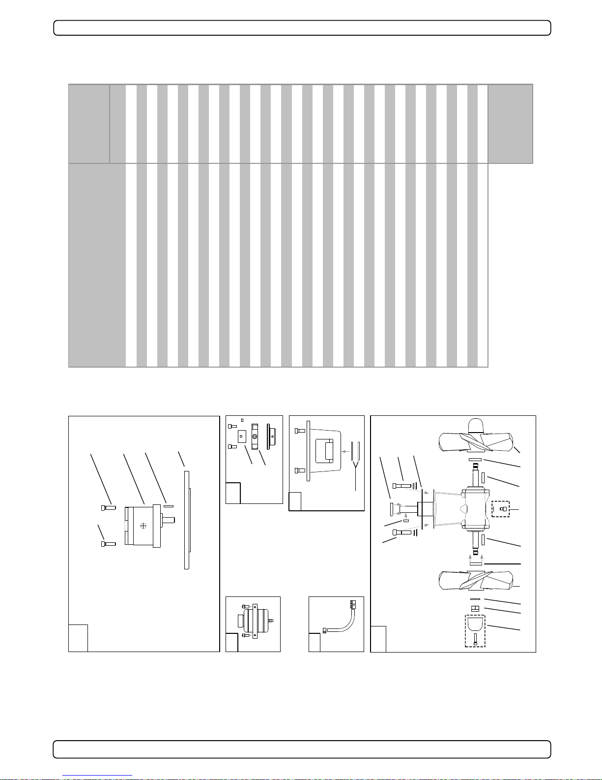
SH100/185T - SP 220 HYD - SP 300 HYD - SP 550 HYD
2.4 - 2007
27
Spareparts SP 300 HYD
Ref:
24. Complete hyd. motor assembly options:
SP300HYD motor, U-10, complete, w /flex. coupling
SP300HYD motor, U-11, complete, w /flex. coupling
SP300HYD motor, U-14, complete, w /flex. coupling
SP300HYD motor, U-16, complete, w /flex. coupling
SP300HYD motor, U-19, complete, w /flex. coupling
23.
Hydraulic motor bolts
22.
Hydraulic motor options:
U-10 (10ccm)
U-11 (11ccm)
U-14 (14ccm)
U-16 (16ccm)
U-19 (19ccm)
21.
Drive shaf t key
20.
Adaptor plate
19. Complete fle xible coupling
18.
Hub flexible coupling
17.
Rubber element
16. Oil container with holder
15. Oil hose with hose clamps
14. Complete motor bracket
13.
O-ring seals in motor bracket
12. Complete gearleg
11.
Gearleg bolt
10.
Drive shaf t key9.Drive shaf t seal8.Propeller shaf t seal7.Gasket6.Oil drain screw with gasket5.Zinc anode4.Locknut3.Propeller w asher2.Propeller key1.Propeller
Model period
11/02 <
Part #
Original model SP 300 HYD
102100UL1
102100UL4
102120UL3
6 1360
102110UL3
102115UL3
20 21301
20 1450HYD
7 1440
72100/U-19
72100/U10
72100/U-14
72100/U-11
72100/U-16
20 0300
20 0400
20 1453
20 1452
20 0600
20 1080
20 0500
20 1340
20 1350
20 1312
10 1440
20 1351
10 1260
20 1181
10 1220
20 1180
Other comments:
?? Need to indicate if
this is a lef t hand (LH)
or right hand (RH)
propeller.
10 1241
20 110??
15
18
17
19
13
14
16
Gear oil EP 90
20
22
24
5 4
3
1 28
6
2 1
7
10
11
11
9
12
8
21
23
23
Page 28

SH100/185T - SP 220 HYD - SP 300 HYD - SP 550 HYD
2.4 - 2007
28
Spareparts SP 550 HYD
Re f :
18. Complete hyd. motor asse mbly options:
SP550HYD motor, U-26, complete, w /flex. coupling
SP550HYD motor, U-29, complete, w /flex. coupling
SP550HYD motor, U-33, complete, w /flex. coupling
SP550HYD motor, U-37, complete, w /flex. coupling
SP550HYD motor, U-50 , complete, w /flex. coupling
SP550HYD motor, P-42, complete, w /flex. c oupling
SP550HYD motor, P-52, complete, w /flex. c oupling
SP550HYD motor, PRO-40, complete, w/flex. coup.
SP550HYD motor, PRO-60, complete, w/flex. coup.
17.
Hydraulic motor options:
U-26 (26ccm)
U-29 (29ccm)
U-33 (33ccm)
U-37 (37ccm)
U-50 (50ccm)
P-42 (42ccm)
P-52 (52ccm)
PRO- 40 (40ccm)
PRO- 60 (60ccm)
16.
Adaptor plate
Adaptor plate for "U" motors
Adaptor plate for "P" and "PRO" motors
15.
Complete flexible c oupling
14. Oil container with holder
13. Oil hose w ith hose clamps
12. Com plete m otor brack et
11.
O-ring seals in motor bracket
10. Gasket (between motor bracket and tunnel)
9. Comple te ge arleg
8.
Gearleg bolt7.Gasket (betw een gearleg and tunnel)6.Oil drain screw w ith gasket5.Zinc anode4.Locknut3.Propeller w asher2.Propeller key1.Propeller
5021302
Original model SP 550 HYD
Model period
01/01 <
Part #
502126UL2
502129UL2
502133UL2
502137UL2
502150UL2
72100/U-26
502142UL
502152UL
502140V2
502160V2
5021301
72100/U-29
72100/U-33
72100/U-37
72100/U-50
72100/P-42
72100/P-52
72100/PRO-40
72100/PRO-60
50 1450HYD
20 0300
20 0400
50 0500
50 1340
50 0600
50 1080
50 1313
50 1220
50 1180
50 1312
50 1260
50 1181
50 1241
50 1270??
Other comments:
?? Need to indicate if
this is a left hand (LH)
or right hand (RH)
propeller.
10
16
15
18
17
14
5 4 3 1 6
2
887
12
11
13
Gear oil EP 90
9
Page 29

SIDEPOWER
Thruster systems
SERVICE
SH100/185T - SP 220 HYD - SP 300 HYD - SP 550 HYD
2.4 - 2007
29
Page 30

SIDEPOWER
Thruster systems
SERVICE
SH100/185T - SP 220 HYD - SP 300 HYD - SP 550 HYD
2.4 - 2007
30
Page 31

SIDEPOWER
Thruster systems
SERVICE
SH100/185T - SP 220 HYD - SP 300 HYD - SP 550 HYD
2.4 - 2007
31
Page 32

SH100/185T - SP 220 HYD - SP 300 HYD - SP 550 HYD
2.4 - 2007
Service Centres
Sleipner Motor AS, P. O. Box 519, N-1612 Fredrikstad, Norway
Tel: +47 69 30 00 60 Fax: +47 69 30 00 70 sidepower@sleipner.no www.side-power.com
Argentina
Trimer SA
Buenos Aires
Tel: +54 11 4580 0444
Fax: +54 11 4580 0440
www.trimer.com.ar
trimer@trimer.com.ar
Australia
AMI Sales
Freemantle, WA
Tel: +61 89 337 3266
Fax: +61 89 314 2929
ami@amisales.com.au
Austria
G. Ascherl GmbH
Hard, Bregenz
Tel: +43 5574 899000
Fax: +43 5574 89900-10
www.ascherl.at
office@ascherl.at
Benelux
ASA Boot Electro
Watergang
Tel: +31 20 436 9100
Fax: +31 20 436 9109
asaboot@worldonline.nl
info@asabootelectro.nl
Canada
Imtra Corporation
New Bedford, MA
Tel: +1 508 995 7000
Fax: +1 508 998 5359
www.imtra.com
side-power@imtra.com
Croatia
AC Yacht & nautical support
Icici
Tel: +385 51 704 500
Fax: +385 51 704 600
acy@net.hr
Denmark
Gertsen & Olufsen AS
Hørsholm
Tel: +45 4576 3600
Fax: +45 4576 1772
www.gertsen-olufsen.dk
info@gertsen-olufsen.dk
Finland
Nautikulma OY
Turku
Tel: +358 2 2503 444
Fax: +358 2 2518 470
www.nautikulma.fi
nautikulma@kolumbus.fi
France
Kent Marine Equipment
Nantes
Tel: +33 240 921 584
Fax: +33 240 921 316
www.kent-marine.com
contact@kent-marine.com
Germany
Jabsco GmbH
Norderstedt
Tel: +49 40 535 373-0
Fax: +49 40 535 373-11
Greece
Amaltheia Marine
Athens
Tel: +30 210 2588 985
Fax: +30 210 2588 986
www.amaltheiamarine.com
amalmar@otenet.gr
Iceland
MARAS EHF
Reykjavik
Tel: +354 555 6444
Fax: +354 565 7230
www.merkur.is
velar@merkur.is
Ireland
Metalcove Marine
Dublin
Tel: +353 1 6795477
Fax: +353 1 6469860
www.metalcove.com
Israel
Atlantis Marine Ltd.
Tel Aviv
Tel: +972 3 522 7978
Fax: +972 3 523 5150
www.atlantis-marine.com
atlantis@inter.net.il
Italy
Saim S.P.A.
Assago-Milan
Tel: +39 02 488 531
Fax: +39 02 488 254 5
www.saim-group.com
Japan
Global Marine Inc.
Hyogo
Tel: +81 798 347 345
Fax: +81 798 347 346
www.global-marine.co.jp
info@global-marine.co.jp
Malta
S & D Yachts Ltd.
Cali
Tel: +356 21 339 908
Fax: +356 21 332 259
www.sdyachts.com
info@sdyachts.com
New Zealand
Lusty & Blundel Ltd.
Auckland
Tel: +64 9 415 8303
Fax: +64 9 415 8304
www.lusty-blundell.co.nz
sales@lusty-blundell.co.nz
Norway
Sleipner Motor AS
Fredrikstad
Tel: +47 69 30 00 60
Fax: +47 69 30 00 70
www.side-power.com
sidepower@sleipner.no
Poland
Taurus Sea Power SP. Z.O.O
Gdansk
Tel: +48 58 344 30 50
Fax: +48 58 341 67 62
Portugal
Krautli Portugal Lda.
Lisboa
Tel: +351 21 953 56 00
Fax: +351 21 953 56 01
www.krautli.com
contact@krautli.pt
Russia
Standarte
Starbeyevo
T
el: +7 095 575 67 23
Fax: +7 095 575 39 77
www.standarte.ru
info@standarte.ru
Spain
Imnasa Marine Products
Girona
Tel: +34 972 820210
Fax: +34 972 325116
www.imnasa.com
imnasa@imnasa.com
Sweden
Sleipner AB
Strömstad
Tel: +46 526 629 50
Fax: +46 526 152 95
www.sleipnerab.se
Switzerland
Marineparts Heimgartner
Volketswil
Tel: +41 1 997 40 90
Fax: +41 1 997 40 94
www.marineparts.ch
info@marineparts.ch
Singapore/Malaysia/
Indonesia
Alquest Marketing
Singapore
Tel: +65 6749 9359
Fax: +65 6749 9360
www.alquest.com.sg
alquest@singnet.com.sg
Taiwan
Mercury Marine Supply
Kaohsiung
Tel: +886 7 3317 293
Fax: +886 7 3314 232
Turkey
Denpar Ltd.
Istanbul
Tel: +90 212 285 0334
Fax: +90 212 285 0311
bilgebay@superonline.com
UK
Sleipner Motor Ltd.
South Brent
Tel: +44 1364 649 400
Fax: +44 1364 649 399
andy@sleipner.co.uk
United Arab Emirates
Teignbridge Propulsion
Dubai
Tel: +971 4 324 0084
Fax: +971 4 324 0153
teignpro@emirates.net.ae
USA
Imtra Corporation
New Bedford, MA
Tel: +1 508 995 7000
Fax: +1 508 998 5359
www.imtra.com
side-power@imtra.com
All other:
Sleipner Motor AS
 Loading...