

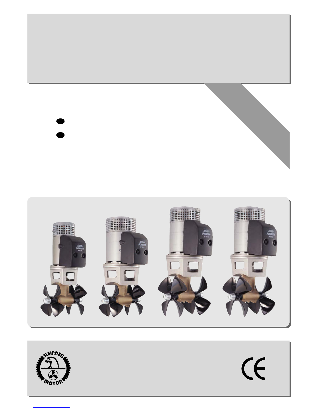
Side-Power SP 155 TC, SP 200 TC, SP 220 TC, SP 285 TC Installation And User Manual
SIDEPOWER
Thruster systems
SP 200 TC 32 Volt
Special SP 285 TC
GB
Installation and user's manual
D
Installations- und Bedienungsanleitung
manual onboard !
Keep this
SLEIPNER MOTOR AS
P.O. Box 519
N-1612 Fredrikstad
Norway
Tel: +47 69 30 00 60
Fax: +47 69 30 00 70
www.side-power.com
sidepower@sleipner.no
©
Sleipner Motor AS 2002
Made in Norway

GB
Contents
Installation instructions
Technical specifications ............................................................ 3
Planning & important precautions ............................................ 4
Tunnel installation
Positioning of the tunnel / thruster ............................................ 5
How to shape the tunnel ends .................................................. 6
How to prevent drag from tunnel installation ........................... 7
Possible tunnel installation in sailboats ................................... 8
Series production installation .................................................... 9
Tunnel installation in a GRP boat ...................................... 10/11
Thruster installation
Gearhouse and motorbracket ................................................. 12
Oil tank & propellers ................................................................ 13
Electromotor ............................................................................. 14
Electrical installation ................................................................ 15
Control panel and control-leads .............................................. 16
Visual / Technical diagram (SP 155 / 200 / 220 TC) ............ 17
Electrical installation (SP 285 TC 48V) .................................. 18
Visual / Technical wiring diagram (SP 285 TC)..................... 19
Checklist for control of the installation ................................... 20
D
Hinweise zur Installation
Technische Daten ...................................................................... 3
Planungs- & Vorsichtshinweise ................................................ 4
Tunnelinstallation
Positionierung von Tunnel / Thruster ....................................... 5
Formgebung der Tunnelenden ................................................. 6
Optimaler Strömungsverlauf am Rumpf ................................... 7
Mögliche Tunnelinstallation in Segelbooten ............................ 8
Installation bei Serienproduktion .............................................. 9
Tunnelinstallation bei Glasfiberrumpf ................................ 10/11
Thrusterinstallation
Getriebe und Motorhalterung .................................................. 12
Ölvorratsbehälter & Propeller .................................................. 13
Elektromotor ............................................................................. 14
Installation der Elektrik ............................................................ 15
Steuerpanel und -kabel ........................................................... 16
Schaltpläne - Übersicht / Techn. (SP 155 / 200 / 220 TC) ... 17
Installation der Elektrik (SP 285 TC 48V) .............................. 18
Schaltpläne - Übersicht / Technisch (SP 285 TC) ................. 19
Checkliste zur Kontrolle der Installation ................................ 20
User's manual
Important user precautions ..................................................... 21
How to use Sidepower thrusters ............................................. 22
Maintenance & service ............................................................ 23
Troubleshooting........................................................................ 24
Warranty statement ............................................................... 26
Spareparts list & drawing .......................................... 27/28/29
Service centres ....................................................................... 32
DECLARATION OF CONFORMITY
We, Sleipner Motor AS
P.O. Box 519
N-1612 Fredrikstad, Norway
declare that this product with accompanying
standard remote control systems complies with
the essential health and safety requirements
according to the Directive 89/336/EEC of 23
May 1989 amended by 92/31/EEC and
93/68/EEC.
Inhalt
Bedienungsanleitung
Benutzerhinweise ..................................................................... 21
Benutzung von Sidepower Thrustern ..................................... 22
Wartung & Service ................................................................... 23
Fehlerbeseitigung..................................................................... 25
Garantieerklärung .................................................................. 26
Ersatzteileliste & -zeichnung .................................... 27/28/29
Service Partner ....................................................................... 32
KONFORMITÄTSERKLÄRUNG
Das von Sleipner Motor AS
P.O. Box 519
N-1612 Fredrikstad, Norwegen
gelieferte Produkt sowie die standard Bedienelemente erfüllen die Gesundheits- und Sicherheitsanforderungen entsprechend der Verordnung 89/
336/EEC vom 23 Mai 1989, Ergänzung 92/31/
EEC und 93/68/EEC.
SP 155 TC / SP 200 TC / SP 220 TC / SP 285 TC 2.0 - 2002
2
Waterline
C
A
F
SP 155 TC SP 200 TC SP 220 TC SP 285 TC
Thrust [kg] 155 200 220 285
A [mm] 250 250 300 300
B [mm] 423 445 445 445
min. [mm] 250 250 300 300
C
D [mm] 300 300 300 300
min. [mm] 7 6 10 10
E
max. [mm] 10 13 13 13
E
Motor output [kW] 8 10 11,2 15
METRIC
Voltage [V] *24 *24 *24 ¤48
Weight [kg] 44 68 70 73
Gear oil capacity [ml] 200 200 250 250
min.: wall thickness of a standard Sidepower tunnel
Note: E
E
max.: maximum wall thickness when using other GRP,
steel or aluminium tunnels
* 12 V Kit available ¤ 24 V Kit included
GB
Motor: Custom made reversible DC-motor.
Gearhouse: Seawater resistant bronze. Angular contact ball
Motor bracket: Seawater resistant aluminium
Tunnel: Cross spun with rowing G.R.P tunnel
Propeller: Symmetrical 4 blade kaplan propellers, fibreglass
Batteries:
Max. use: S2 = 3 min. or appr. 7-10% within a limited time
:
Safety
Technical specifications
bearing at propellershaft and combination of ball
bearing and needle bearing at driveshaft.
Steel & aluminum tunnels available at request.
reinforced composite.
Minimum recommended battery capacity
(cold crank capacity by DIN standard)
SP 155 TC 24V : 500 CCA DIN/950 CCA SAE
SP 200 / 220 TC 24V : 700 CCA DIN/1330 CCA SAE
SP 285 TC 48V : 2 x 450 CCA-24v DIN/2 x 855 CCA-24v SAE
frame.
Electronic time-lapse device protects against
sudden change of drive direction. Electric thermal
cut-off switch in electromotor protects against over
heating (auto reset when electro motor cools down).
Flexible coupling between electromotor and
driveshaft to protect electromotor and gearsystem
if propeller gets jammed.
If original Sidepower panel is used, the panel
shuts off automatically after 30 minutes.
SP 155 TC SP 200 TC SP 220 TC SP 285 TC
Thrust [lbs] 341 440 484 627
A [in] 9,84 9,84 11,81 11,81
B [in] 16,65 17,52 17,52 17,52
min. [in] 11,81 9,84 11,81 11,81
C
D [in] 9,84 11,8 11,81 11,81
min. [in] 0,28 0,24 0,39 0,39
E
max. [in] 0,39 0,51 0,51 0,51
E
Motor output [Hp] 10,7 13,5 15 20
IMPERIAL
Voltage [V] *24 *24 *24 ¤48
Weight [lbs] 97 150 154 160
Gear oil capacity [fl.oz] 6,763 6,736 8,45 8,45
min.: wall thickness of a standard Sidepower tunnel
Note: E
E
max.: maximum wall thickness when using other GRP,
steel or aluminium tunnels
* 12 V Kit available ¤ 24 V Kit included
D
Motor: Gleichstrommotor
Getriebegeh.: Seewasserbeständige Bronze. Winkelkontakt-
Motorhalterung:Seewasserbeständiges Aluminium
Tunnel: Glasfibertunnel (Kreuzgewebe)
Propeller: Symmetrische, 4 flügeliger Kaplanpropeller aus
Batterie:
Betriebszeit: S2 = 3 min. oder ca. 7-10% innerhalb eines
Sicherheit
:
Technische Daten
kugellager an der Propellerachse, Kombination
von Kugel- und Nadellager an der Antriebsachse.
Stahl- & Aluminiumtunnel auf Anfrage.
Glasfiberverbundmaterial.
Empfohlene mind. Batteriekapazität
(Kaltstartkapazität nach DIN)
SP 155 TC 24V : 500 CCA DIN
SP 200 / 220 TC 24V : 700 CCA DIN
SP 285 TC 48V : 2 x 450 CCA-24 V
beliebigen Zeitraumes.
Elektronische Zeitverzögerung zum Schutz des
Getriebes bei plötzlichem Wechsel der Drehrichtung. Elektrischer Thermoschalter zum Schutz
des Motors gegen Überhitzung (erneute Betriebsbereitschaft nach Abkühlung).
Elastische Kupplung zwischen Elektromotor und
Getriebeachse als Schutz, wenn der Propeller
blockiert ist.
Original Sidepower Kontrollpanels, schalten sich
30 Minuten nach der letzten Aktivierung
automatisch ab.
SP 155 TC / SP 200 TC / SP 220 TC / SP 285 TC 2.0 - 2002
3

GB
Planning and important precautions
Prior to installation, it is important that the installer reads this guide to ensure necessary acquaintance with this product.
The thruster must NOT be installed in compartments that require ignition proof electric equipment. If necessary, make a seperate compartment.
The electromotor will generate some carbon dust so that any storage compartment must be separated from the thruster to prevent
the stored items from becoming dusty/dirty.
If you are installing the Sidepower in a small room/compartment, it should be ventilated to ensure good cooling of the electromotor.
If the height in the room you are installing the Sidepower is limited, the Sidepower can be installed horizontally or at any angle in between.
If the electro motor is positioned more than 30
o
off vertical, it must be supported separately.
The electromotor must be handled carefully. Do not lift it by the internal connections or put it down on the driveshaft.
Beware to keep installation within adviced measurements. No part of the propeller or gearhouse must be outside the tunnel.
The electromotor, its components, contacts / plugs or other joints in the controlcables must be mounted so that they will keep dry at all times.
W e advice to paint the gearhouse and propellers with antifouling. PS! Do not paint the zinc anodes, sealings or propellershafts.
Do not finish the inside of the tunnel with a layer of gelcoat / topcoat or similiar. It is only room for a thin layer of primer and two layers of
anti-fouling between the tunnel and the props.
W ith the boat on land, do not run the thruster, as without resistance it will accelerate very fast to a damaging rpm.
This manual is intended to support educated / experienced staff and is therefore not sufficient in all details for the correct installation.
o
Don't install the electromotor at close range to easily flammable objects as it will reach over 100
C before the temp. switch is activated.
Do not store items close to the thruster motor as it gets hot as well as any loose items near the thruster motor can cause
problems with electrical wiring coming loose and shortcircuiting.
When installed in boats approved or classified according to international or special national rules, the installer is responsible for
following the demands in accordance with these regulations / classification rules. The instructions in this guide can not be guaranteed
to comply with all different regulations / classification rules.
NB ! Faulty installation of the tunnel, thruster or panel will render all warranty given by Sleipner Motor AS void.
D
Planungs- und Vorsichtshinweise
Dieses Manual vor der Installation lesen, um ausreichende Kenntnisse über das Produkt zu erlangen.
Der Thruster darf nicht in Räumen installiert werden, die funkenflugfrei sein müssen. Falls nötig ein eigenes Abteil schaffen.
Der Elektromotor verursacht Karbonstaub, deshalb sollte jeder Lagerraum vom Thruster abgetrennt werden, damit gelagerte
Gegenstände nicht verschmutzt/staubig werden.
W ird der Sidepower in einem kleinen Raum / Abteil installiert, so ist dieser zur ausreichenden Kühlung zu ventilieren.
Wenn die verfügbare Höhe begrenzt ist, kann der Sidepower in jedem Winkel bis zur Horizontalen eingebaut werden.
0
Wird der Motor mehr als 30
außerhalb der Vertikalen eingebaut, so muß dieser abgestützt werden.
Mit dem Elektromotor vorsichtig umgehen. Nicht an den Anschlüssen anheben oder auf die Antriebswelle absetzen.
Die Installation innerhalb der vorgegebenen Maße halten. Es darf kein Teil des Systems aus dem Tunnel herausstehen.
Der Elektromotor, Kontakte, Stecker und andere Verbindungen müssen so installiert werden, daß sie stets trocken bleiben.
Auf Getriebegehäuse und Propeller Antifouling auftragen. PS ! Zinkanoden, Dichtungen, Propellerachse nicht bemalen.
Die Innenseite des Tunnels nicht mit Gelcoat / Topcoat o.ä. behandeln. Nur eine dünne Schicht Primer und zwei Schichten Antifouling
auftragen, da zwischen dem Tunnel und den Propellern nur ein geringer Zwischenraum besteht.
Den Thruster an Land nur weniger als eine Sekunde betreiben, da ohne den Wasserwiderstand der Elektromotor beschädigt wird.
Dieses Manual ist für Fachleute ausgelegt. Es sind daher nicht alle notwendigen Details für eine korrekte Installation enthalten.
o
Da der Motor über 100
C erreichen kann, darf dieser nicht in der Nähe von leicht entflammbaren Objekten installiert werden.
Da der Elektromotor sehr heiß werden kann, keine Gegenstände in dessen Nähe lagern. Auch lose Gegenstände in der Nähe des
Elektromotors können zu Problemen mit elektrischen Leitungen bis hin zu Kurzschlüssen führen.
Bei Abnahmepflicht nach nationalen oder internationalen Bestimmungen, ist der Installateur für die Einhaltung dieser Bestim-
mungen verantwortlich. In diesem Leitfaden können zwangsläufig nicht alle weltweit geltenden Bestimmungen berücksichtigt werden.
NB ! Bei falscher Installation von Tunnel, Thruster oder Kontrollpanel besteht keinerlei Garantieanspruch.
SP 155 TC / SP 200 TC / SP 220 TC / SP 285 TC 2.0 - 2002
4

Fig. 1
Fig. 2
Pivot
point
min.
1/3Ø
B = 10,0m
A = 11,0m
Ø
min.
1/3Ø
A
B
min.
1/2Ø
☺
3/4Ø
1/1 Ø
☺ ☺
30 - 35 cm*
Fig. 3
Fig. 4
GB
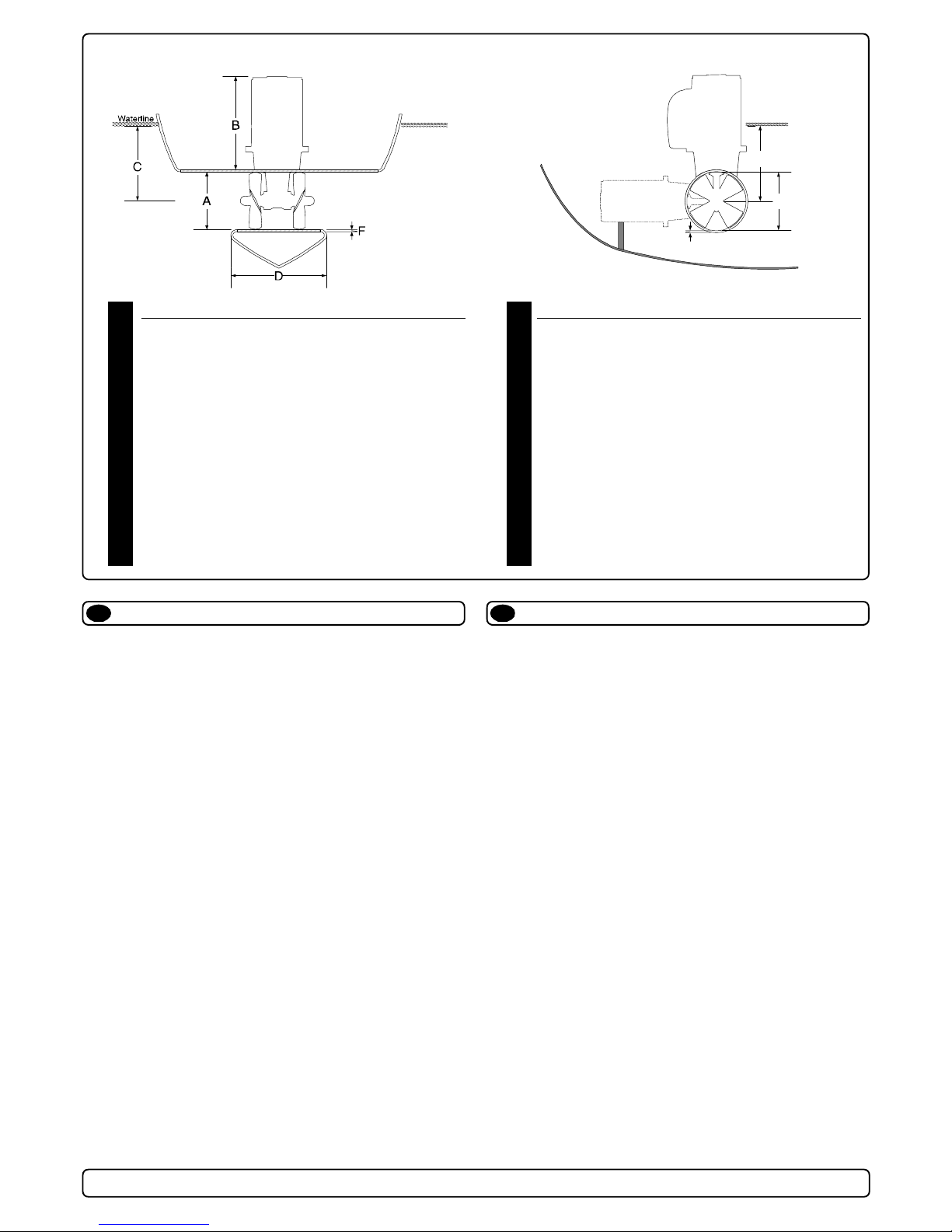
Positioning of the tunnel / thruster
The Thruster should be as far forward as possible (Fig. 1)
Because of the leverage effect around the boats pivot point, it is very
important for the thrusters actual effect in the boat to get it as far forward as possible. The relative distance change from the boats pivot
point to the thruster will be the change of actual thrust for the boat.
Example:
A:55kg thrust x 11m leverage = 605kgm torque to rotate the boat
B:55kg thrust x 10m leverage = 550kgm torque to rotate the boat
In position A you will get 10% more thrust to turn the boat around.
The thruster should be placed as deep as possible (Fig. 2)
The tunnel should be placed as deep as possible for two reasons:
1. So that it does not suck down air from the surface which will
destroy the thrust completely.
2. To get as high as possible a water pressure to get maximum
efficiency from the propeller.
Generally the top of the tunnel should be a minimum of 1/2 x the
tunnel diameter below the waterline. This is an absolute minimum
and we recommend that it is at least 3/4 x tunnel diameter (☺)
below the waterine. A really good distance is about 1/1 x tunnel
diameter (☺☺) below the waterline.
When you get the top of the tunnel 30-35 cm* / 1 feet below the
surface, other factors should be considered more important, i.e.
moving the thruster further forward.
Optimal tunnel length
If the tunnel gets to long, the friction inside will reduce the water
speed and thereby the thrust.
If the tunnel gets to short (normally only in the bottom section of the
tunnel) you can get cavitation problems as the water will not have
had time to “straigthen” itself before reaching the propeller (Fig. 3/4).
This caviation will reduce performance as well as creating a lot of
noise.
The optimal tunnel length is 2 to 4 x tunnel diameter and you
should avoid tunnels longer than 6 to 7 times the tunnel diameter
as the performance reduction is then clearly noticeable.
D
Positionierung von Tunnel / Thruster
Tunnelplazierung soweit vorne wie möglich (Fig. 1)
Um einen möglichst großen Abstand vom Drehpunkt des Schiffes zu
erreichen, ist der Sidepower möglichst weit vorne einzubauen.
Eine Vergrößerung des Abstandes vom Drehpunkt des Schiffes
hat eine direkte Auswirkung auf die verfügbare Schubkraft.
Beispiel :
A: 55kg Schubkraft x 11m = 605kgm zum Wenden des Bootes
B: 55kg Schubkraft x 10m = 550kgm zum Wenden des Bootes
In Beispiel A stehen damit 10% mehr Schubkraft zur Verfügung.
Den Tunnel so tief wie möglich positionieren (Fig. 2)
Den Tunnel aus zwei Gründen so tief wie möglich positionieren:
1. Damit nicht Luft mitangesaugt wird, die die Schubkraft
vollständig herabsetzt.
2. Um einen möglichst hohen Wasserdruck zu erhalten, um die
maximale Effizienz des Propellers erreichen.
Die Oberkante des Tunnels muß mind. einen halben Tunneldurchmesser unterhalb der Wasserlinie liegen. Dieser Wert ist ein
absolutes Minimum. Besser ist ein Wert von ca. 3/4 des
Tunneldurchmessers (☺). Optimal ist eine Abstand von 1/1 x
Tunneldurchmesser (☺☺) zur Wasserlinie.
Liegt die Oberkante des Tunnels 30-35cm* / 1fuß unterhalb der
Wasserlinie, können andere Faktoren berücksichtigt werden.
Optimale Tunnellänge
Bei einem zu langem Tunnel reduziert der Reibungsverlust die
Wassergeschwindigkeit und damit die Schubkraft.
Bei einem zu kurzem Tunnel (häufig im unteren Bereich des
Tunnels) können Kavitationsprobleme entstehen, da sich das
Wasser nicht gerade auszurichten kann (Fig. 3/4). Diese Kavitation ist leistungsreduzierend und kann starken Lärm verursachen.
Die optim. Tunnellänge ist das 2-4 fache des Tunneldurchmessers.
Tunnellängen von mehr als dem 6-7 fachen des Tunneldurchmessers sollten vermieden werden, da dadurch die Leistung
reduziert wird.
SP 155 TC / SP 200 TC / SP 220 TC / SP 285 TC 2.0 - 2002
5
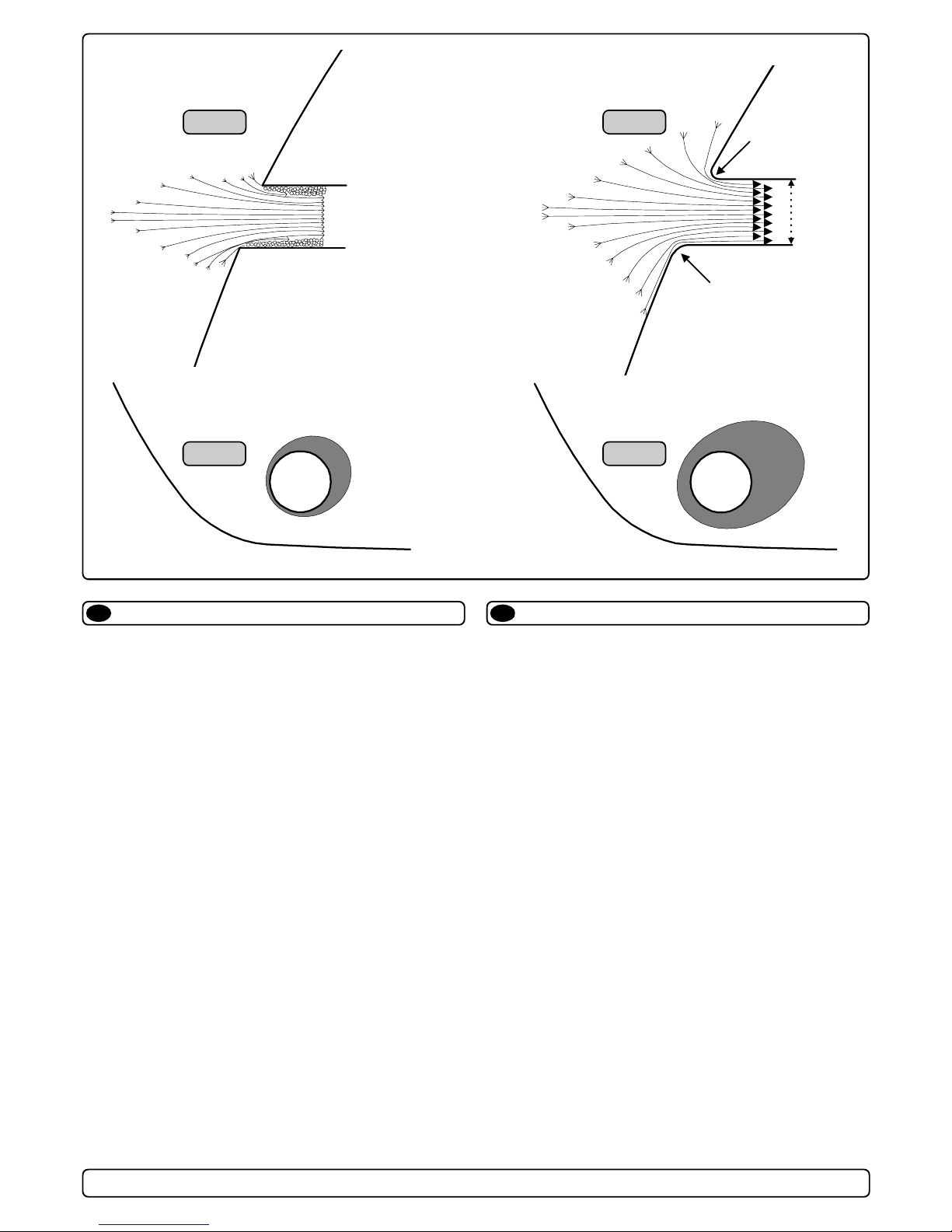
Fig. 1
Fig. 2
R = 0,1 x D (10%)
D
R = 0,1 x D (10%)
Fig. 3
GB D
Rounded tunnel ends will maximize thrust and minimize
noise.
We recommend to round the tunnel connection to the hull-side as
much as possible.
The optimum rounding has a radius of 10% of the tunnels diameter.
Important advantages over sharp tunnel to hull connections are:
1. The rounded tunnel end will prevent creation of turbulence /
cavitation that will come from a sharp tunnel end when water
passes by fast, thereby preventing a double negative impact on
the thrust and noise level (Fig. 1&2 ).
- The turbulence / cavitation blocks the outer area of the tunnel
and thereby reduces the effective tunnel diameter and thrust.
- The turbulence / cavitation hits the propeller and thereby
reduce the propellers performance and creates noise.
2. The angled tunnel end makes the thruster take water also from
along the hull-side, creating a vacuum that will suck the boat
sideways and thereby give additional thrust (Fig. 3&4). With a
sharp tunnel end, the thruster will be unable to take water from
along the hull-side, and you will not get the desired vacuum and
additional thrust.
This "free" additional thrust can in optimal installations be as
much as 30-40% of the total thrust.
Tunnel ends
☺
Fig. 4
Formgebung der Tunnelenden
Abgerundete Tunnelenden erhöhen die Schubkraft und
reduzieren das Geräuschniveau.
Der Bereich Tunnelende / Außenseite des Rumpfes ist soweit
möglich abzurunden. Der optimale Wert für den Radius dieser
Rundung beträgt 10% des Tunneldurchmessers.
Vorteile gegenüber einer scharfen Tunnel / Rumpfverbindung sind:
1. Abgerundete Tunnelenden verhindern Turbulenzen / Kavitation,
wie sie an scharfenkantigen Tunnelenden auftreten. Damit
werden zwei negative Auswirkungen auf Schubkraft und
Geräuschentwicklung vermieden (Fig. 1&2).
- Turbulenz / Kavitation blockieren den äußeren Tunnelbereich.
Dadurch werden effektiver Tunneldurchmesser und Schubkraft reduziert.
- Die Turbulenz / Kavitation trifft auf den Propeller und reduziert
dessen Effektivität und führt zu zusätzl. Geräuschentwicklung.
2. Abrundungen ermöglichen, daß Wasser entlang der Rumpfaußenseite angesaugt werden kann. Dadurch entsteht ein
Vakuum ("zusätzliche" Schubkraft"), das das Schiff seitwärts
bewegt (Fig. 3&4). Bei scharfkantigen Enden kann kein Wasser
entlang der Rumpfaußenseite angesaugt werden, wodurch das
benötigte Vakuum nicht zustande kommt.
Diese Schubkraft kann bei optimaler Installation bis zu 30-40%
der absoluten Schubkraft betragen.
NB! A Sidepower thruster propeller does not cavitate at working
speed so that all cavitation and cavitation noise in the tunnel
will be caused by the tunnel installation.
NB! Even if it is not possible to make the perfect rounding, it is
very important to round the tunnel end as much as possible.
A angled tunnel to hull connection will also do much of the
same job as a rounded connection (see page 20, Fig. 1b&1d).
SP 155 TC / SP 200 TC / SP 220 TC / SP 285 TC 2.0 - 2002
NB ! Sidepower Propeller sind so ausgelegt, daß sie nicht
kavitieren, sodaß die Geräuschentwicklung aufgrund von
Kavitation durch die Tunnelinstallation bedingt ist.
NB ! Ist eine optimale Abrundung nicht möglich, so sind die
Tunnelenden soweit möglich abzurunden. Angeschrägte
Tunnel / Rumpfverbindungen sind zu einem gewissen Grad
ebenfalls mit ähnlich positiven Auswirkungen wie eine
Abrundung verbunden (siehe Seite 20, Fig. 1b&1d).
6
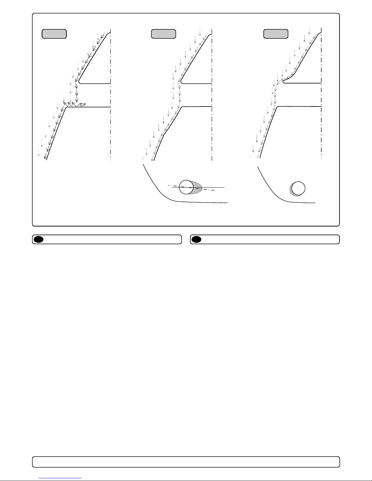
Fig. 2Fig. 1 Fig. 3
GB
A possible problem in sailboats or fast powerboats, is that they get
a drag from the back face of the tunnel, as this becomes a “flat”
area facing the water flow (Fig. 1).
This can also create problems with the thruster spinning (passive)
and making noise while sailing or driving the boat with water being
pushed through the tunnel at high speed.
This can be solved in two different ways, depending on what is
possible or more easy to do.
1. The best solution which normally reduces the drag most, is to
make a recess in the hull at the back of the tunnel.
Thereby the back face is gone and about all the drag (Fig. 2).
The depth and shape of this insert will depend on the boat.
Basically you should not see the back face of the tunnel when
standing directly in front of the tunnel at the angle of the boats
centreline.
The angle up or down backwards of the insert in the hull,
depends on the hullshape, but normally it is angled slightly
down because of the waterflow on this area of the hull.
2. The drag will also be reduced a lot, especially in fast power
boats, by making a deflector / spoiler in front of the tunnel.
This will push the waterflow out from the hull so that most of it
passes by the back face of the tunnel (Fig. 3).
The shape and size of this deflector will depend on the hull
shape. Basically you should not see the back face of the tunnel
when standing directly in front of the tunnel at the angle of the
boats centreline.
The easiest way of making this is to let a part of the tunnel stick
out in the lower forward area of the hole, and use this as a
support to mould a soft curve / spoiler shape.
Prevent drag from tunnel
☺
D
Optimaler Strömungsverlauf am Rumpf
Segelboote und sehr schnelle Booten können gelegentlich durch
auf die rückseitige Fläche des Tunnels auftreffendes Wasser
gebremst werden (Fig. 1).
Dies kann dazu führen, daß sich der Thruster durch den permanenten Wasserdurchfluß hörbar passiv zu drehen beginnt.
Das Problem kann je nach Möglichkeit auf zwei Arten beseitigt
werden.
1. Der störende Effekt wird am deutlichsten reduziert, indem man
im Rumpfbereich hinter dem Tunnel eine Aussparung vornimmt.
Dadurch werden Auftreffläche und störender Effekt eliminiert
(Fig. 2).
Tiefe und Form dieser Aussparung hängen vom Boot ab.
Die Innenseite des Tunnels sollte von vorne prinzipiell nicht
sichtbar sein.
Der mögliche Winkel der Aussparung hängt meist von der
Rumpfform ab. Bedingt durch die Wasserströmung in diesem
Bereich sollte dieser Winkel leicht nach unten gerichtet sein.
2. Der Geschwindigkeitsverlust kann speziell bei schnellen Booten
durch einen Abweiser bzw. Spoiler vor dem Tunnel deutlich
reduziert werden.
Das Wasser wird so beeinflußt, daß es größtenteils an der
frontalen Fläche vorbei geleitet wird (Fig. 3).
Form und Größe des Abweisers hängen von der Rumpfform ab.
Prinzipiell sollte auch hier die Innenseite des Tunnels von vorne
nicht sichtbar, sondern durch den Abweiser verdeckt sein.
Dieser läßt sich einfach realisieren, indem man den Tunnel ein
Stück aus dem Rumpf herausstehen läßt und darauf einen
geschwungenen Abweiser / Spoiler formt.
☺
Remember to still round the tunnel ends as much as possible to
get optimum thruster performance and minimum noise.
More information on how to practially do this on pages 11.
SP 155 TC / SP 200 TC / SP 220 TC / SP 285 TC 2.0 - 2002
Die Tunnelenden sind zur vollen Leistung und minimalen
Geräuschentwicklung des Thrusters weitgehend abzurunden.
Weitere Informationen siehe Seite 11.
7
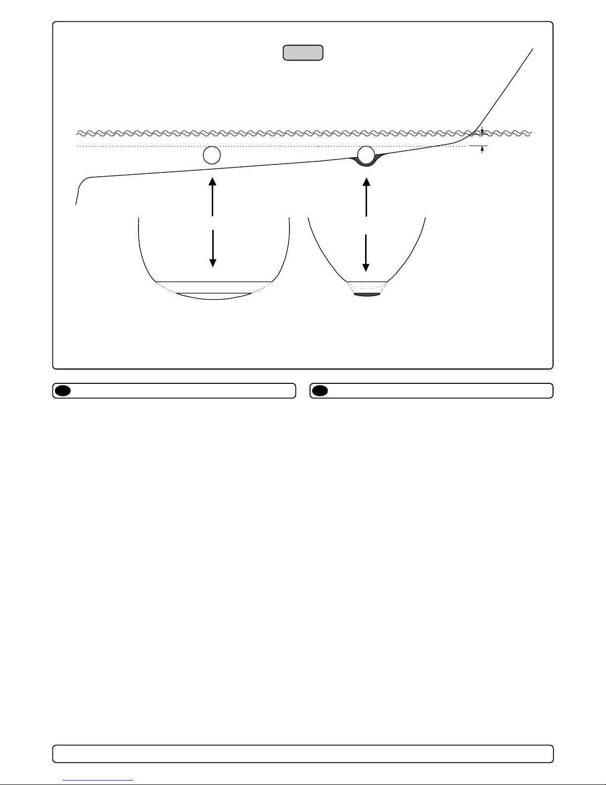
Fig. 1
☺
Min
Pos. A
☺
GB
Many sailboats have a racing type hull which means that it is very
flat bottomed and has a very shallow draft in the bow section. It is
thereby very difficult not to say impossible to fit a tunnel thruster the
usual way, atleast as far forward in the hull as a thruster should be
(Fig. 1).
However, it is possible to install a tunnel thruster in most sailboats,
even when the hull does not directly support the fitting of a tunnel.
This is done by fitting the tunnel halfway into and halfway underneath the exisiting hull and then strengthen it and smoothening the
waterflow by moulding a bulb around / underneath the tunnel.
This will allow installation in good position on the boat, maintaining
the reliability and space advantages of a tunnel thruster.
This installation is being used by some of the worlds largest
sailboat builders, and have been proven to give little to no speed
loss for normal cruising.
This can also be a good installation method for flat bottomed
barges to avoid extremely long tunnels and huge oval tunnel
openings in the hull.
Tunnel installation in sailboats
Pos. B
D
Segelboote weisen häufig einen Rumpf in Rennform auf, was
einen sehr flachen Rumpf im Bugbereich bedeutet. Es ist daher
schwierig oder fast unmöglich, den Tunnel an der gewünschten
(effektivsten) Stelle, also möglichst weit vorne im Bug zu plazieren
(Fig. 1).
Trotzdem ist es vielfach möglich unter diesen Bedingungen eine
Bugschraube einzubauen, auch wenn der Tunnel damit nicht völlig
vom ursprünglichen Rumpf umgeben ist.
Der Tunnel wird zur Hälfte in den bestehenden Rumpf integriert,
die andere Hälfte geht über diesen hinaus. Der Tunnel muß nur
noch verstärkt und strömungsgünstig abgerundet werden.
Dies erlaubt eine Installation in geeigneter Position bei Nutzung
der Zuverlässigkeits- und Platzvorteile einer Tunnelschraube.
Diese Installationsart wird von einigen der weltweit führenden
Segelboothersteller verwendet und führt meistens nur zu einem
äußerst geringen bzw. gar keinem Geschwindigkeitsverlust.
Diese Bauweise ist auch für Barkassen (z.B. Flußboote) mit
flachem Bug geeignet, um einen zu langen Tunnel und große
ovale Tunnelöffnungen im Rumpf zu vermeiden.
Installation in Segelbooten
SP 155 TC / SP 200 TC / SP 220 TC / SP 285 TC 2.0 - 2002
8
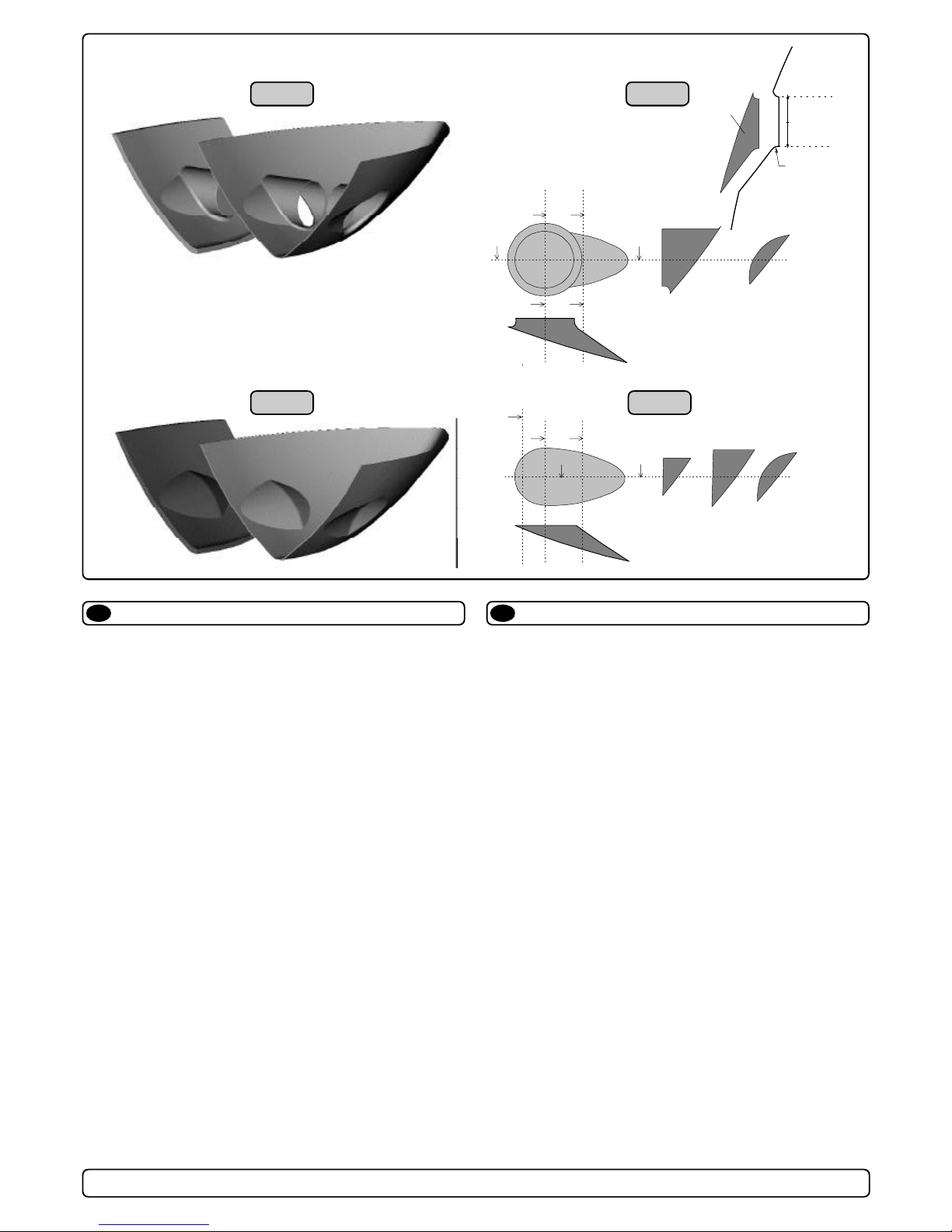
Fig. 1
=
c1
Fig. 2
A
a2
a1
b
a2
a1
b
a1
D
Radius
D x 0,1
a2
b
Fig. 3
GB
Boat builders having thrusters as standard, or delivering a large
portion of one or more models with thrusters, have the opportunity
to make a perfect tunnel installation, while saving both time and
money on each installation (Fig. 1).
The solution is to make an insert / plug in the hull mould, which
prepares the hull for an easy tunnel installation with features for
maximum thrust and minimal drag (Fig. 2).
This insert / plug in the mould is not very difficult to make, and as it
will have to be a "bolt on" in the mould in order to get the boat out,
you can still make boats without this hull feature. (Some boat
builders have this in the hull also on boats that are delivered
without a thruster as they know many people will fit this later)
By having a flat surface to fit the tunnel to, the installation time and
cost for the tunnel will also be reduced as:
- it is very easy and fast to cut the now circular hole for the tunnel
- it is easier to mould inside all around the tunnel
- you save tunnel length
The plug in the mould can also be made so that it can be a fixed
part of the mould, but the rounded end option must then be made
later to get the hull out of the mould (Fig. 3&4).
Series production installation
Fig. 4
c2
c3
d
c1
d
c2 c3
d
D
Installation bei Serienproduktion
Hersteller die Thruster als Standard oder Modelle mit Bug- bzw.
Heckschrauben anbieten, haben die Möglichkeit einer kosten- und
zeitsparenden Tunnelinstallation (Fig. 1), die trotzdem maximale
Schubkraft bei minimaler Geräuschentwicklung erlaubt.
Durch eine Ausformung in der Rumpfform (fest oder als Einsatz),
kann der Tunnel später auf einfache Art und Weise installiert
werden (Fig. 2).
Die Ausformung / Einsätze sind relativ einfach herzustellen, sollten
aber nur mit der Form verschraubt werden, da sie mit dem Rumpf
aus der Form genommen werden müssen. Dadurch können auch
Rümpfe ohne Tunnelvorbereitung hergestellt werden. (Da viele
Kunden nachträglich einen Thruster einbauen, liefern einige
Hersteller bereits alle Einheiten mit fertiger Tunnelvorbereitung.)
Durch die gerade Oberfläche zur Aufnahme des Tunnels werden
Installationszeit und -kosten reduziert da:
- sich das kreisförmige Loch sehr einfach und schnell aus dem
Rumpf ausschneiden läßt
- der Tunnel sich auf der Innenseite einfacher mit dem Rumpf
verbinden läßt
- die Tunnellänge reduziert wird
Der Einsatz kann auch fester Bestandteil der Form sein, allerdings
müssen die Tunnelenden dann nachträglich abgerundet werden,
um den Rumpf aus der Form zu lösen zu können (Fig. 3&4).
SP 155 TC / SP 200 TC / SP 220 TC / SP 285 TC 2.0 - 2002
9
 Loading...