

Page 1
Keep this
manual onboard !
N
Installasjon og brukermanual
Installation and user's manual
EN
Made in Norway
©
Sleipner Motor AS 2012
SLEIPNER MOTOR AS
P.O. Box 519
N-1612 Fredrikstad
Norway
Tel: +47 69 30 00 60
Fax:+47 69 30 00 70
www.side-power.com
sidepower@sleipner.no
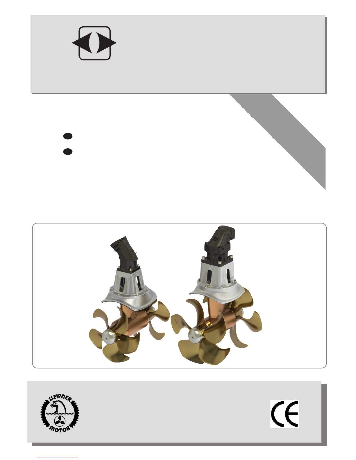
SH 1000/513 TC
SH 1400/610 TC
Mechanical thruster installation only
SIDE-POWER
Thruster Systems
Page 2

SH1000/513TC- SH1400/610TC 1.3 - 2012
2
Innhold
N
INSTALLATION INSTRUCTIONS
Technical specications .......................................................... 3/4
Planning & important precautions.............................................. 5
Tunnel installation
Positioning of the tunnel / thruster ............................................ 6
How to shape the tunnel ends ................................................... 7
How to prevent drag from tunnel installation ............................. 8
Possible tunnel installation in sailboats ..................................... 9
Series production installation................................................... 10
Tunnel installation in a GRP boat ....................................... 11/12
Thruster installation
Gearhouse and motorbracket .................................................. 13
Propeller .................................................................................. 14
Hydraulic motor ....................................................................... 15
Oil tank .....................................................................................16
Hydraulic installation................................................................ 17
Maintenance & service .............................................................18
Checklist for control of the installation ..................................... 19
USER'S MANUAL
Important user precautions .......................................................20
How to use Side-Power thrusters ............................................ 20
Warranty statement .............................................................. 21
Spareparts list & drawing .................................................... 22
Service centres ..................................................................... 24
Contents
EN
DECLARATION OF CONFORMITY
We, Sleipner Motor AS
P.O. Box 519
N-1612 Fredrikstad, Norway
declare that this product with accompanying
standard remote control systems complies with
the essential health and safety requirements
according to the Directive 89/336/EEC of 23
May 1989 amended by 92/31/EEC and
93/68/EEC.
INSTALLASJONSVELEDNING
Tekniske spesikasjoner ......................................................... 3/4
Tunnelinstallasjon
Plassering av tunnel/truster ...................................................... 6
Hvordan forme tunnelendene .................................................... 7
Hvordan forhindre motstand fra tunnelinstallasjon .................... 8
Alternativer for installasjon i seilbåt ........................................... 9
Installasjon ved serieproduksjon ............................................. 10
Tunnellinstallasjon i en glassberbåt .................................. 11/12
Trusterinstallasjon
Girhus og brakett ..................................................................... 13
Propeller .................................................................................. 14
Hydraulikkmotor og kobling ..................................................... 15
Oljetank ....................................................................................16
Hydraulisk installasjon ............................................................. 17
Service og vedlikehold..............................................................18
Sjekkliste for kontroll av installasjonen .................................... 19
BRUKERMANUAL
Viktige forhåndsregler ...............................................................20
Hvordan bruke Side-Power trustere ........................................ 20
Deleliste og tegning ............................................................. 22
Servicesentere ...................................................................... 24
SAMSVARSERKLÆRING
Vi , Sleipner Motor AS
Postboks 519
N -1612 Fredrikstad,Norge
erklærer at dette produktet med tilhørende
standard kontrollsystemer er i samsvar med
helse, og sikkerhetskravene i henhold til Direktiv 89/336/EEC fra 23 Mai 1989, korrigert av
92/31/EEC og 93/68/EEC.
Page 3

SH1000/513TC- SH1400/610TC 1.3 - 2012
3
Technical specications
EN
Port side Starboard side
SH1000 SH1400
Light duty thrust [kg] 1200 1600
Heavy duty thrust [kg] 1000 1400
A [mm] 513 610
B [mm] 486 500
C min. [mm] 700 830
D [mm] 750 750
D recommended [mm] 900 900
E recommended [mm] 16 18
E min/max. [mm] 12/22 14/24
Hydraulic power [kW] 62 82
Gear oil capacity [ml] 4500 4500
Note: E recommended.: wall thickness of a standard Sidepower tunnel
E min/max: minimum/maximum wall thickness when using
other GRP, steel or aluminium tunnels
Tekniske data
N
Motor: Hydraulic type (specications next page)
Gear house: Seawater resistant bronze
Gears: Hardened precision gears
Lubrication: Oil bath from tank (gear oil GL-5)
Bearings: Angular contact ball bearing at propellershaft
and combination of ball bearing and needle
bearing at driveshaft.
Material: Seawater resistant bronze, protected with
anodes
Motor bracket: Seawater resistant aluminium
Tunnel: Cross spun with rowing G.R.P tunnel
Steel & aluminum tunnels available at request.
Propellers: Symmetrical Bronze 5-blade skew "Q-PROP"
Control panel: Not supplied as standard
Safety: Flexible coupling between hydraulic motor and
driveshaft protects gearsystem against peak
loads.
SH1000 SH1400
Light duty thrust [lbs] 2646 3527
Heavy duty thrust [lbs] 2205 3086
A [in] 20.2 24
B [in] 19.1 19.7
C min. [in] 27.6 32.7
D [in] 29.5 29.5
D recommended [in] 35.4 35.4
E recommended [in] 0.63 0.71
E min/max. [in] 0.47/0.87 0.55/0.94
Hydraulic power [Hp] 83 110
Gear oil capacity [.oz] 152.2 152.2
Note: Emin.: wall thickness of a standard Sidepower tunnel
Emax.: maximum wall thickness when using other GRP,
steel or aluminium tunnels
IMPERIALMETRIC
Motor: Hydraulisk type (spesikasjoner neste side).
Girhus: Sjøvannsbestandig bronsje.
Tannhjul: Herdede presisjonstannhjul
Smøring: Oljebad fra tank (GL-5 girolje)
Lager: Vinklede kulelager på propellaksel og kombinas-
jon av kulelager og nålelager på drivaksel
Material: Sjøvannsbestandig bronse, med anodebeskyt-
telse
Motorbrakett: Sjøvannsbestandig aluminium.
Tunnel: Kryssvevet glassber.
Aluminium og ståltunnel på forespørsel.
Propell: Symmetrisk 5-blads skewback "Q-prop" propell i
sjøvannsbestandig bronsje
Kontrollpanel: Ikke inkludert som standard
Sikkerhet: Fleksibel kobling mellom hydraulisk motor og
girhus beskytter drivsystemet mot overbelastning
Page 4
SH1000/513TC- SH1400/610TC 1.3 - 2012
4
Requirements / Hydraulic hose connections to motor
Port A Port B Drain port
Motor type Port A/B Port ange threads Drain port
G70 1 1/4" BSP - 1/4" BSP
G75 1 1/4" BSP - 1/4" BSP
BA80 1" 6000 PSI SAE J518/ ISO 6162 Code 62 7/16-14 UNC-2B 19 deep 7/8"-14 UNF
BA90 1" 6000 PSI SAE J518/ ISO 6162 Code 62 7/16-14 UNC-2B 19 deep 7/8"-14 UNF
BA110 1 1/4" 6000 PSI SAE J518/ ISO 6162 Code 62 1/2-13 UNC-2B 19 deep 1 1/16-12 UNF
BA125 1 1/4" 6000 PSI SAE J518/ ISO 6162 Code 62 1/2-13 UNC-2B 19 deep 7/8"-14 UNF
BA160 1 1/4" 6000 PSI SAE J518/ ISO 6162 Code 62 1/2-13 UNC-2B 19 deep 7/8"-14 UNF
BA180 1 1/4" 6000 PSI SAE J518/ ISO 6162 Code 62 1/2-13 UNC-2B 19 deep 7/8"-14 UNF
(Must be installed)
60 % 70 % 80 % 90 % 100 %
Flow Pressure Flow Pressure Flow Pressure Flow Pressure Flow Pressure
SH1000
G70 L/min -Bar 91,0 220 99,0 256
USG-PSI 24.0 3190 26.2 3712
G75 L/min -Bar 98,0 205 106,0 239
USG-PSI 25.9 2973 28.0 3466
BA80 L/min -Bar 90,4 188 98,0 220 104,4 251 111,0 282
USG-PSI 23.9 2726 25.9 3190 27.6 3640 29.3 4089
BA90 L/min -Bar 99,5 167 107,0 195 115,0 225 122,0 251 128,5 279
USG-PSI 26.3 2422 28.3 2828 30.4 3263 32.2 3640 40.0 4046
BA110 L/min -Bar 122,0 139 131,4 132 140,5 185 149,0 208 157,0 231
USG-PSI 32.2 2016 34.7 1914 37,1 2683 39.4 3016 41.5 3350
SH1400
BA125 L/min -Bar 113,0 197 122,4 230 131,0 263 139,0 296
USG-PSI 29.9 2857 32.3 3335 34.6 3814 36.7 4292
BA150 L/min -Bar 139,0 164 150,0 192 160,4 219 170,0 247 179,4 274
USG-PSI 36.7 2378 39.6 2784 42.4 3176 44.9 3582 47.4 3973
BA160 L/min -Bar 145,0 154 157,0 180 167,5 205 178,0 231 187,0 257
USG-PSI 38.3 2233 41.5 2610 44.3 2973 47.0 3350 49.4 3727
BA180 L/min -Bar 163,0 137 176,0 160 188,5 183 200,0 205 211,0 228
USG-PSI 43.0 1987 46.5 2320 49.8 2654 52.8 2973 55.7 3306
Performance table
Page 5

SH1000/513TC- SH1400/610TC 1.3 - 2012
5
Prior to installation, it is important that the installer reads this guide to ensure necessary acquaintance with this product.
This manual is intended to support educated / experienced staff and is therefore not sufcient in all details for the correct installation.
If the height in the room you are installing the Sidepower is limited, the Sidepower can be installed horizontally or at any angle in between.
The motor must be handled carefully.
Beware to keep installation within adviced measurements. No part of the propeller or gearhouse must be outside the tunnel.
The motor, its components or other joints and contol cables must be mounted so that they will keep dry at all times.
We advice to paint the gearhouse and propellers with antifouling. PS! Do not paint the zinc anodes, sealings or propellershafts.
Do not nish the inside of the tunnel with a layer of gelcoat / topcoat or similiar. It is only room for a thin layer of primer and two layers
of anti-fouling between the tunnel and the props.
When installed in boats approved or classied according to international or special national rules, the installer is responsible for
following the demands in accordance with these regulations / classication rules. The instructions in this guide can not be guaranteed
to comply with all different regulations / classication rules.
If no original Sidepower hydraulic system is installed, please ensure the following:
Install an oil lter to keep the oil clean.
Fit an oil cooler or use an oiltank so that the maximum oil temperature is 43 - 50 degrees Celcius.
This thruster is supplied with a hydraulic motor only.
The rest of the hydraulic system is the responsibility of the tter/installer and must be within the limitations that are described in this
manual so that it does not damage the thruster.
It is very important to use a hydraulic valve that has ow and pressure limits that are either set within or can be adjusted to be within
the limits of the thrusters capability.
We also strongly recommend that a shock valve are tted and set to 10% - 15% above the chosen maximum pressure set in the
valve. This will prevent that the system is dammaged if the propellers are blocked by any reason.
It is also required that a device is installed to ensure that the drive direction can not be suddenly changed, as this can seriously
dammage the gearhouse. This can be done by adding an electronic time lapse / delay safety on the electric control system or by
using a valve that has this type of protection built in. The required time delay is 1 second.
NB ! Faulty installation of the tunnel, thruster or panel will render all warranty given by Sleipner Motor AS void.
Planning and important precautions
EN
Page 6
SH1000/513TC- SH1400/610TC 1.3 - 2012
6
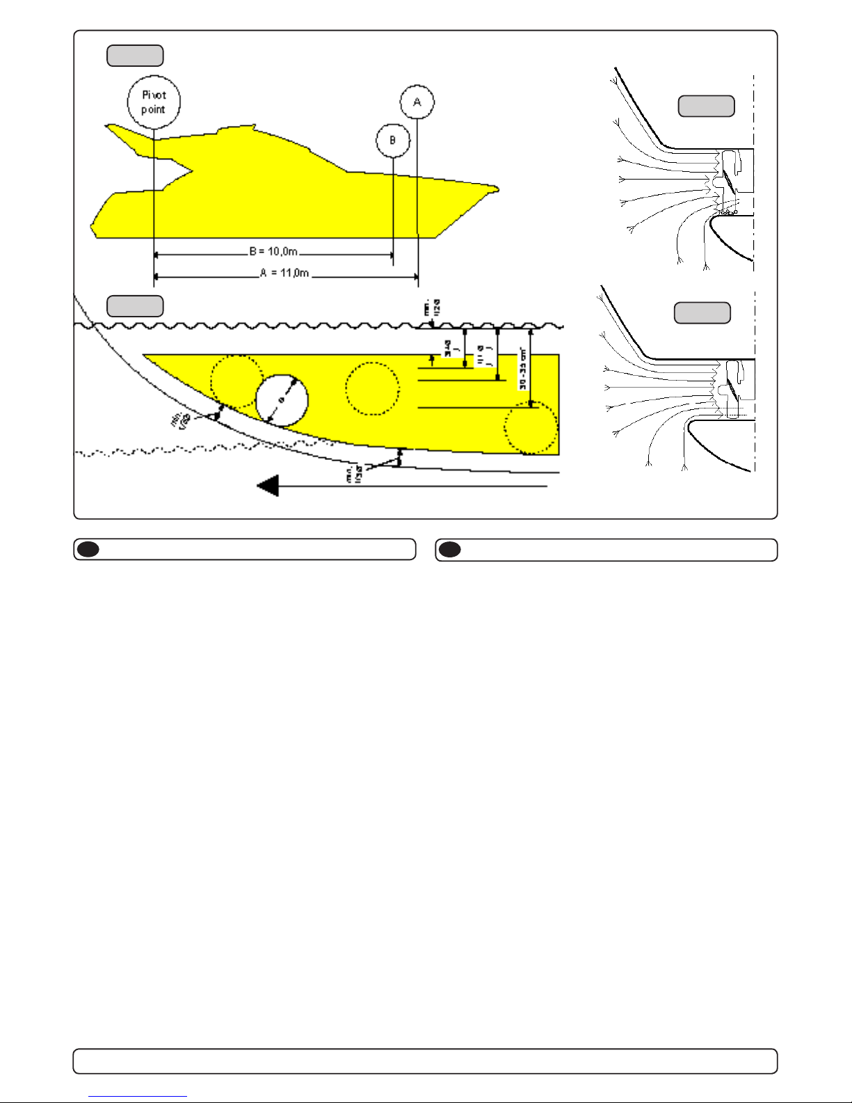
The Thruster should be as far forward as possible (Fig. 1)
Because of the leverage effect around the boats pivot point, it is
very important for the thrusters actual effect in the boat to get it
as far for-ward as possible. The relative distance change from the
boats pivot point to the thruster will be the change of actual thrust
for the boat.
Example :
A: 100kg thrust x 11m leverage = 1100kgm torque to rot. the boat
B: 100kg thrust x 10m leverage = 1000kgm torque to rot. the boat
In position A you will get 10% more thrust to turn the boat around.
The thruster should be placed as deep as possible (Fig. 2)
The tunnel should be placed as deep as possible for two reasons:
1. So that it does not suck down air from the surface which will
destroy the thrust completely.
2. To get as high as possible a water pressure to get maximum
efciency from the propeller.
Generally the top of the tunnel should be a minimum of 1/2 x the
tunnel diameter below the waterline. This is an absolute minimum
and we recommend that it is at least 3/4 x tunnel diameter ()
below the waterine. A really good distance is about 1/1 x tunnel
diameter () below the waterline.
When you get the top of the tunnel 30-35 cm* / 1 feet below the
surface, other factors should be considered more important, i.e.
moving the thruster further forward.
Optimal tunnel length
If the tunnel gets to long, the friction inside will reduce the water
speed and thereby the thrust.
If the tunnel gets to short (normally only in the bottom section of
the tunnel) you can get cavitation problems as the water will not
have had time to “straigthen” itself before reaching the propel-
ler (Fig. 3/4). This cavitation will reduce performance as well as
creating a lot of noise.
The optimal tunnel length is 2 to 4 x tunnel diameter and you
should avoid tunnels longer than 6 to 7 times the tunnel diameter
as the performance reduction is then clearly noticeable.
Positioning of the tunnel / thruster
EN
Fig. 1
Fig. 2
Fig. 3
Fig. 4
Plassering av tunnel og thruster
N
Tunnelen bør plasseres lengst mulig frem i baugen (Fig. 1)
For å oppnå mest mulig moment rundt båtens dreiepunkt, er det
meget viktig å plassere tunnelen så langt fremme som mulig.
Avstanden fra båtens dreiepunkt til thruster vil ha stor betydning
på thrusterens effekt.
Eks.:
A: 55kg skyvekraft x 11m moment = 605kgm skyvekraft
B: 55kg skyvekraft x 10m moment = 550kgm skyvekraft
Posisjon A vil gi 10% mer skyvekraft til rotasjon.
Tunnelen skal plasseres dypest mulig (Fig. 2)
Tunnelen skal plasseres så dypt som mulig av to grunner:
1. Så luft ikke suges ned i tunnelen og ødelegger skyvekraften.
2. Ved å øke vanntrykket jobber propellen mer effektivt.
Hovedregelen er at tunnelen skal plasseres minimum ½ x tun-
nelen dia. under vannlinje. Anbefalt dybde er minst ¾ x dia. under
vannlinje (). Når tunnelen er plassert 33-35 cm under vannlinjen
bør andre faktorer vurderes som viktigere, d.v.s. å plassere tun-
nelen lengre frem.
Optimal tunnel lengde
Dersom tunellen blir for lang vil friksjonen i tunellen reduser vannhastigheten og derved effekten.
Dersom tunellen blir for kort (normalt bare i nedre del av tunel-
len) kan det oppstå kavitasjons problemer da vannet ikke har tid
/ av-stand til å «rette opp strømningsretningen» før det treffer
propellen (Fig. 3&4). Denne kavitasjonen vil redusere effekten og
lage mye støy.
Den optimale tunell lengden er 2 til 4 ganger tunell diameteren
og dersom tunellen blir så mye som 6 til 7 ganger diameteren i
lengde vil effekt tapet bli klart merkbart.
Page 7
SH1000/513TC- SH1400/610TC 1.3 - 2012
7
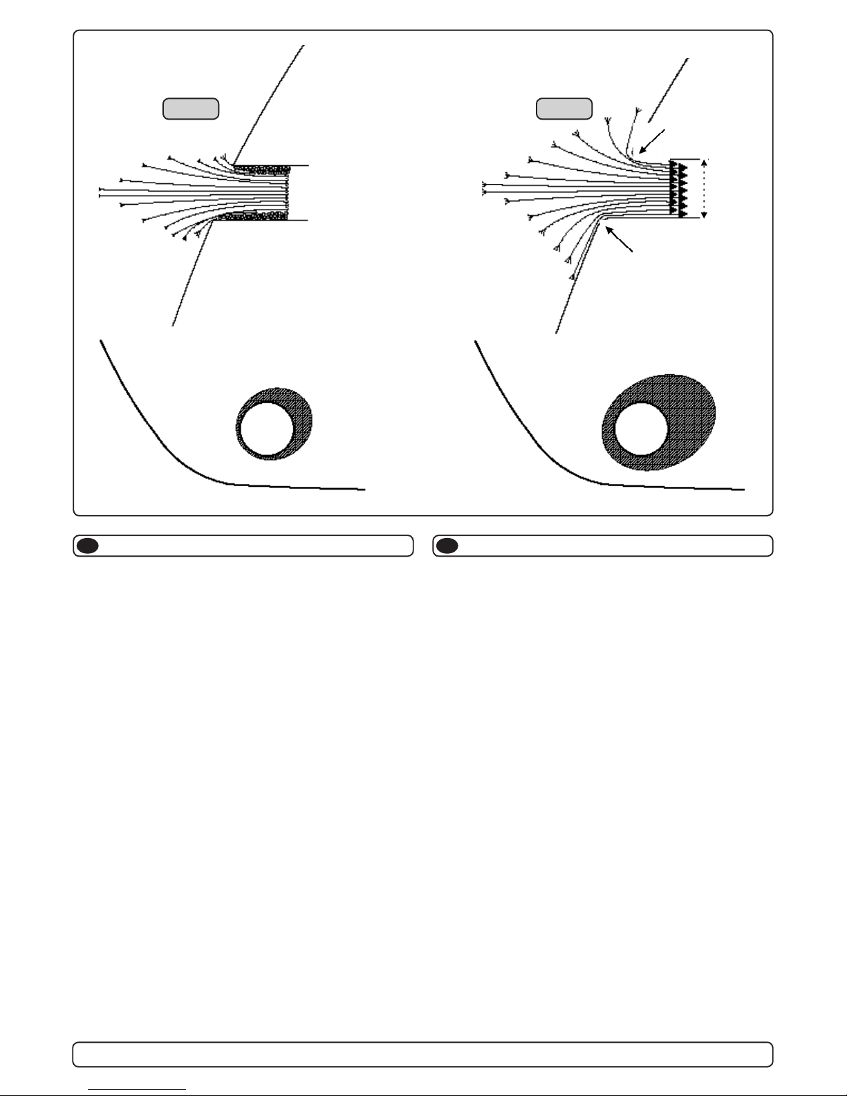
Rounded tunnel ends will maximize thrust and minimize noise.
We recommend to round the tunnel connection to the hull-side as
much as possible.
The optimum rounding has a radius of 10% of the tunnels diameter.
Important advantages over sharp tunnel to hull connections are:
1. The rounded tunnel end will prevent creation of turbulence /
cavitation that will come from a sharp tunnel end when water
passes by fast, thereby preventing a double negative impact on
the thrust and noise level (Fig. 1&2).
- The turbulence / cavitation blocks the outer area of the tunnel
and thereby reduces the effective tunnel diameter and thrust.
- The turbulence / cavitation hits the propeller and thereby
reduce the propellers performance and creates noise.
2. The curved tunnel end makes the thruster take water also from
along the hull-side, creating a vacuum that will suck the boat
sideways and thereby give additional thrust (Fig. 3&4).
With a sharp tunnel end, the thruster will be unable to take
water from along the hull-side, and you will not get the desired
vacuum and additional thrust.
This "free" additional thrust can in optimal installations be as
much as 30 - 40% of the total thrust.
NB! A Sidepower thruster propeller does not cavitate at working
speed so that all cavitation and cavitation noise in the tunnel will be caused by the tunnel installation.
NB! Even if it is not possible to make the perfect rounding, it is
very important to round the tunnel end as much as possible.
A angled tunnel to hull connection will also do much of the
same job as a rounded connection (see page 20, Fig. 1b&1d).
Tunnel ends
EN
Fig. 2
Fig. 4
Fig. 1
Fig. 3
R = 0,1 x D (10%)
R = 0,1 x D (10%)
D
Tunnelåpninger
N
Avrundede åpninger vil minke støy, og maksimere effekt.
Vi anbefaler å avrunde tunnelåpningene mest mulig.
Den optimale avrundingen har en radie som er 10% av tunnelens
diameter.
Hvorfor er en avrundet tunnelåpning så viktig?
1. En avrundet tunnelåpning vil forhindre at det oppstår turbu-
lens / kavitasjon, noe som vil oppstå ved en installasjon med
skarpe kanter. Turbulensen forårsaker mer støy, og begrenser
skyvekraften.
- Turbulensen / kavitasjonen blokkerer tunnelen og svekker
skyvekraften.
- I det kavitasjon og turbulens når propellen påvirkes ytelsen til
denne og øker støyen.
2. En avrundet tunnelåpning gjør også at thrusteren suger vann
langs skroget på båten. Dermed oppstår det et lavtrykk som
vil hjelpe å suge båten i dreieretningen. Med skarpe åpninger
klarer ikke thrusteren å suge vann langs skroget, og lavtrykket
uteblir. Så mye som 40% av skyvekraften har blitt målt til å
ligge her på noen installasjoner.
NB! Propellene til Side-Power thrustere kaviterer ikke på arbeid-
shastighet, så kavitasjon og støy som oppstår som følge av
kavitasjon, skapes av tunnelinstallasjonen.
NB! Selv der en perfekt avrunding ikke er mulig er det viktig å
runde av kantene så mye som mulig, en tunnelåpning med
skråkant vil ha stor effekt fremfor en med skarpkant (se side
20, ill. 1b & 1d).
Page 8
SH1000/513TC- SH1400/610TC 1.3 - 2012
8
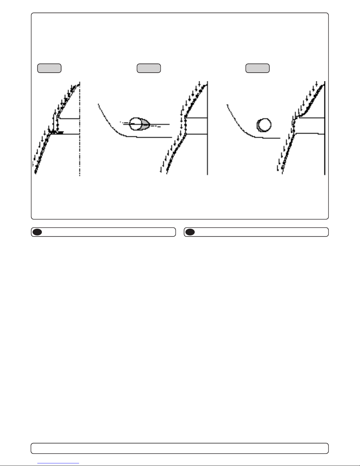
A possible problem in sailboats or fast powerboats, is that they
get a drag from the back face of the tunnel, as this becomes a
“at” area facing the water ow (Fig. 1).
This can also create problems with the thruster spinning (passive)
and making noise while sailing or driving the boat with water being pushed through the tunnel at high speed.
This can be solved in two different ways, depending on what is
possible or more easy to do.
1. The best solution which normally reduces the drag most, is to
make a recess in the hull at the back of the tunnel.
Thereby the back face is gone and about all the drag (Fig. 2).
The depth and shape of this recess will depend on the boat.
Basically you should not see the back face of the tunnel when
standing directly in front of the tunnel at the angle of the boats
centreline.
The angle up or down backwards of the insert in the hull, de-
pends on the hullshape, but normally it is angled slightly down
because of the waterow on this area of the hull.
2. The drag will also be reduced a lot, especially in fast power
boats, by making a deector / spoiler in front of the tunnel.
This will push the waterow out from the hull so that most of it
passes by the back face of the tunnel (Fig. 3).
The shape and size of this deector will depend on the hull
shape. Basically you should not see the back face of the tunnel
when standing directly in front of the tunnel at the angle of the
boats centreline.
The easiest way of making this is to let a part of the tunnel
stick out in the lower forward area of the hole, and use this as
a support to mould a soft curve / spoiler shape.
Remember to still round the tunnel ends as much as possible to
get optimum thruster performance and minimum noise.
More information on how to practially do this on pages 6.
Prevent drag from tunnel
Fig. 2
Fig. 1
Fig. 3
EN
Motstand forårsaket av tunnel
N
Et mulig problem for seilbåter eller meget hurtiggående båter er
motstand i tunnelen. Aktre ende på tunnelen vil være en liten loddrett ate mot vannstrømmen som skaper uønsket motstand.
Denne aten kan også forårsake problemer med at vann føres
inn i tunnelen under seilas, eller kjøring i høy fart og får da propellen til å rotere, dette skaper uønsket støy.
Det er to mulige løsninger på problemet, avhengig av hva som er
enklest å få til på båten.
1. Den løsningen som vanligvis reduserer motstanden mest er å
lage en fordypning i skroget i aktre ende av tunnelåpningen.
Den loddrette aten vil da forsvinne og dermed motstanden.
Hovedregelen å følge er at bakkanten av tunnelen ikke skal
synes når man står rett foran båten og titter akterover langs
båten senterlinje. Dybden, utformingen og vinkling av fordypningen avhenger av båttypen, og hvordan vannet følger skroget, men de este båter vil være tjent med en fordypning som
vinkler lett nedover (Fig. 2).
2. Motstanden vil også reduseres av en spoiler i forkant av
tunnelen. Spoileren fører det meste av vannstrømmen rundt
og forbi tunnelen. Størrelsen og utformingen på spoileren
avhenger av båten. Hovedregelen er at bakkanten av tunnelen
ikke skal synes når man står rett foran båten og titter akterover
langs båten senterlinje. Den enkleste måten å lage spoileren
på er å la tunnelen stikke ut i forkant av tunnelen, og forme
spoileren opp mot den (Fig. 3).
Det er alltid viktig å avrunde tunnelåpningene mest mulig for å
motvirke støy og for å få mest mulig effekt av thrusteren.
Mer informasjon om dette på side 10.
Page 9

SH1000/513TC- SH1400/610TC 1.3 - 2012
9
Many sailboats have a racing type hull which means that it is very
at bottomed and has a very shallow draft in the bow section. It is
thereby very difcult not to say impossible to t a tunnel thruster
the usual way, at least as far forward in the hull as a thruster
should be (Fig. 1).
However, it is possible to install a tunnel thruster in most sail-
boats, even when the hull does not directly support the tting of a
tunnel.
This is done by tting the tunnel halfway into and halfway under-
neath the exisiting hull and then strengthen it and smoothening
the waterow by moulding a bulb around / underneath the tunnel.
This will allow installation in good position on the boat, maintaining
the reliability and space advantages of a tunnel thruster.
This installation is being used by some of the worlds absolute
largest sailboat builders, and have been proven to give little to no
speed loss for normal cruising.
This can also be a good installation method for at bottomed
barges to avoid extremely long tunnels and huge oval tunnel
openings in the hull.
Tunnel installation in sailboats
EN
Fig. 1
Pos. B
Pos. A
Tunnelinstallasjon på seilbåter
N
Mange seilbåtskrog er bygget for å oppnå høy fart. De har brede
skrog som ikke stikker dypt i baugen. Skrogtypen gjør det vanskelig å installere en thrustertunnel på vanlig måte, spesielt med
tanke på å plassere den langt nok frem (Fig. 1).
Thrustertunneler kan allikevel installeres i de este seilbåter.
Dette gjøres ved å la en del av tunnelen stikke ut i underkant av
skroget. Tunnelen er sterk nok til dette, og thrusteren blir plassert
lav nok og langt nok fremme.
Dette gjøres ved at øvre halvdel av tunnelen støpes inn i skroget,
tunnelen styrkes i underkant ved å støpe en kul rundt tunnelen og
jevne den ut mest mulig.
Denne metoden brukes av noen av de helt største seilbåt-produsentene i verden, de viser til at den ikke gir utslag på fart under
normal seilas.
Denne installasjonen kan også være gunstig for båter med ate
bunner, for å unngå ekstremt lange tunneler og store ovale tunnelåpninger.
Page 10

SH1000/513TC- SH1400/610TC 1.3 - 2012
10
Boat builders having thrusters as standard, or delivering a large
portion of one or more models with thrusters, have the opportunity to make a perfect tunnel installation, while saving both time
and money on each installation (Fig. 1).
The solution is to make an insert / plug in the hull mould, which
prepares the hull for an easy tunnel installation with features for
maximum thrust and minimal drag (Fig. 2).
This insert / plug in the mould is not very difcult to make, and as
it will have to be a "bolt on" in the mould in order to get the boat
out, you can still make boats without this hull feature. (Some boat
builders have this in the hull also on boats that are delivered with-
out a thruster as they know many people will t this later)
By having a at surface to t the tunnel to, the installation time
and cost for the tunnel will also be reduced as:
- it is very easy and fast to cut the now circular hole for the tunnel
- it is easier to mould inside all around the tunnel
- you save tunnel length
The plug in the mould can also be made so that it can be a xed
part of the mould, but the rounded end option must then be made
later to get the hull out of the mould (Fig. 3&4).
Series production installation
Fig. 1
Fig. 3
Fig. 2
Fig. 4
EN
a1
b
a1
a2
a2
b
a1
a2
b
D
Radius =
D x 0,1
A
a1
b
a1
a2
a2
b
a1
a2
d
d
c1
c2
c2 c3
d
b
c3
c1
Båtbyggere som har trustere som standard eller leverer en eller
ere modeller med valgfri truster i stort antall har mulighet for å
lage en perfekt tunnelinstallasjon og samtidig spare tid å penger
(Fig. 1).
Løsningen er å lage en plugg/innsats i formen, som klarrgjør
skroget for anklest mulig tunnelinstallasjon og som samtidig har
perfekt utforming for maksimal trust og minimal motstand (Fig. 2).
Pluggen/innsatsen er ikke komplisert å lage og siden den må
skrus fast i formen på grunn av slipp kan skrogene fremdeles
lages uten denne løsningen. (Enkelte båtbyggere velger også
denne løsningen på båter levert uten truster da de vet at mange
vil velge å ettermontere en truster)
Ved å ha en rett ate å montere tunnelen på, reduseres installasjonstiden og kostnaden for tunnelen siden:
- det blir eldig enkelt og raskt å skjære ut det nå sirkulære hullet
til tunnelen
- det er enklere å støpe inn tunnelen langs hele omkretsen
- du sparer lengde på tunnelen
Pluggen i formen kan også lages på en slik måte at den inngår
som en fast del, men da må avrundingen lages etterpå for å
oppnå slipp i formen (Fig. 3&4).
Installasjon ved serieproduksjon
N
Page 11

SH1000/513TC- SH1400/610TC 1.3 - 2012
11
We recomend that a professional does the breglass tting
of the tunnel. These instructions are only general, and do not
explain in any way the details of breglass work. Problems
caused by faulty installation of the tunnel, are the installers
full responsibility.
Find the position in the boat considering the information given
earlier in this manual and the applicable measurements for the
thruster model you are installing.
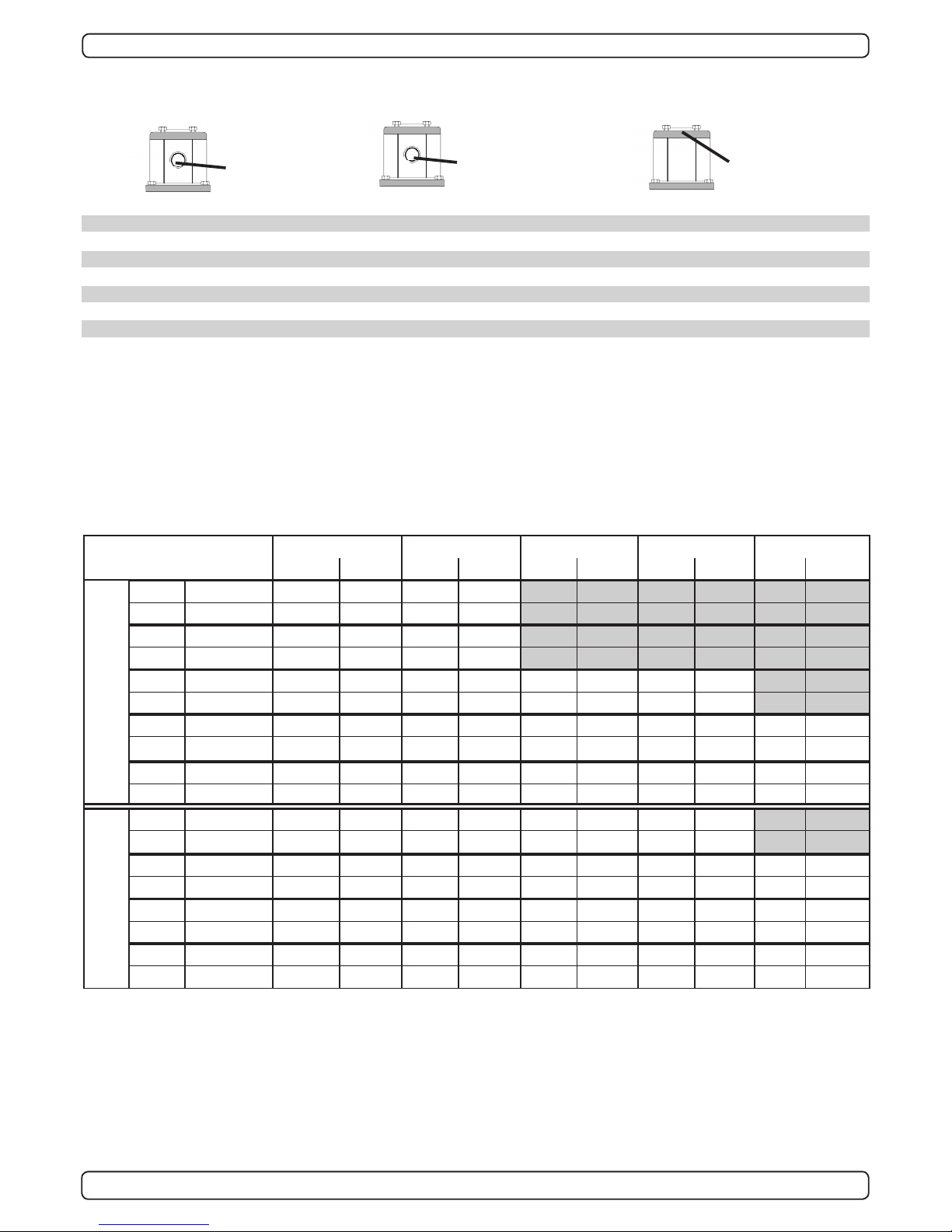
Mark the centre of the tunnel on both sides. Drill a 6mm hole
horizontally in these marks (Fig. 1) .
Bend a ø 5mm steel bar as shown with the "tip" bent back at the
tunnel radius and mark the circle for the tunnel opening (outside
diameter of the tunnel). Cut the hole with a jigsaw (Fig. 2).
Grind off the gelcoat and polyester so that you are down in the
“real breglass” in an area of 12cm around the hole both inside
and outside in the hull to cast the tunnel to the hull (Fig. 3).
Insert the tunnel and mark its shape to t the hull (Fig. 4). If you
are installing with a deector/spoiler, leave a part or the tunnel of
the front- and underside of the tunnel to have a base for this (see
page 12, Fig. 2). Cut the tunnel ends to the desired shape and
lightly sand its surface and clean with aceton or similar where you
are going to apply breglass.
NB! Do not cast/glass on the area were the thruster will be
placed.
Then cast the tunnel to the inside of the hull, use at least 8 layers
of 300 g glass and resin, preferrably alternating mat and rowing
types of breglass (see page 18, Fig. 1). If you are rounding the
tunnel ends to the perfect 10% radius you may in some cases
have to make further layers inside to preserve the desired hull
thickness.
NB ! Make sure that any gap between the tunell and the hull are
completely lled with resin/breglass. In areas where you can not
access to make normal layers of resin/breglass, a resin/ breglass mixture must be lled in that area.
R
D
Tunnel installation
Fig. 1
Fig. 3
Fig. 4
Fig. 2
EN
Tunnelinstallering
N
Sleipner Motor anbefaler at innstøping av glassbertunnelen
utføres av kyndig personell. Denne instruksjons manualen gir ikke detaljerte opplysninger om glassberstøpning.
Problemer som skyldes installering er installatørens fulle
ansvar.
Bestem plassering av tunnelen ut i fra informasjonen gitt tidligere
i manualen, og de angitte mål for thrusteren du skal installere.
Merk av senter på tunnelen på babord og styrbord side. Bor et 6
mm vannrett hull, på begge sider (Fig. 1).
Bøy til og tilpass en 5 mm stålstang, som vist på g. 2 der den
tilbakebøyde enden skal markere tunnelens radius. Stikk enden
inn å marker tunnelens ytre diameter, skjær ut hullet med en
stikksag (Fig. 2).
Puss av gelcoat og polyester så glassberen ligger bar i et 12 cm
stort område rundt tunnel hullet. Dette må gjøres på innsiden og
utsiden av skroget, før tunnelen støpes fast i skroget (Fig. 3).
Sett inn tunnelen å marker hvor det skal kappes for å passe i
skroget (Fig. 4). Hvis det skal støpes en spoiler i forkant av tunnelen bør en del av tunnelen stikke ut i for og underkant av skroget for å støpe spoileren mot (Side 10, Fig. 2). Kapp tunnelen i
ønsket størrelse. Slip lett med slipepapir, og vask med aceton der
hvor det skal støpes med glassber.
NB ! Det må ikke støpes der hvor thrusteren skal monteres.
Støp fast tunnelen først på innsiden av skroget, bruk minst 8 lag
med 300 g Glassbermatte, og polyester. Ved bruk av alternative
materialer, glassber matter eller rovingtyper (Se s. 10, Fig. 1).
Hvis tunnelåpningene avrundes til den optimale 10% radius må
ofte legge ekstra lag med polyester glassbermatte på innersiden
av tunnelen, for å oppnå riktig tykkelse i forhold til skrogtykkelsen.
NB ! Forsikre deg om at overgangene mellom tunel og skrog er
nøye sammenstøpt. På steder en ikke kommer til med vanlige lag
med polyester/glassber matte, sørg for og lage en blanding av
polyester og glassber, som fylles i dette.
Page 12

SH1000/513TC- SH1400/610TC 1.3 - 2012
12
Soften the edges with a radius of 10% of the tunnel diameter
(Fig. 1a) or make a slope with a length of 10 - 15% of the tunnel
diameter (Fig. 1c). If this is not possible, atleast round the tunnel
end as much as possible.
We advice to also cast two layers on the outside of the tunnel/
hull for an area 6-8cm (Fig. 1c&1d).
You must apply gelcoat/topcoat/epoxy on the areas outside where
you have grounded or moulded to again make these waterproof.
NB ! All original Sidepower tunnels are fully waterproof
when they are delivered.
This means that unless you want, because of special reasons, to
have another colour on it, you do not have to apply Gelcoat/Topcoat or the several layers of primer that is necessary on the boats'
hull to make it waterresistant.
Sand it very lightly and apply one layer of primer to make the
antifouling sit.
The original Sidepower tube itself is fully waterresistant without
treatment exceptin the areas where you have bonded it to the
hull.
Apply gelcoat/topcoat/epoxy paint and primer on the areas where
you have grounded or moulded as these areas give the water
access to the hull which normally is not waterproof without these
applications outside.
PS ! Avoid all casting where the motor-bracket is to be
placed, as this will cause mist and possible failure of
the gearhouse.
Tunnel installation
EN
Fig. 1a
Fig. 1
Fig. 1b
Fig. 2
Fig. 3
Fig. 1d
Fig. 1c
Tunnelinstallering
N
Rund av tunnelendene med en radius 10% av tunneldiameter
(Fig. 1a), eller lag en skråkant 10-15% av tunneldiameter (Fig.
1c). Der dette ikke er mulig skal tunnel kantene rundes av mest
mulig.
Vi anbefaler å støpe to lag utenpå tunnelavrundingen og over et
område på 6-8cm (Fig. 1c & 1d).
Gelcoat eller lignende må påføres på områdene der det har blitt
pusset eller støpt for å gjøre glassberen vanntett.
NB ! Alle originale Side-Power tunneler er vanntette ved leve-
ring!
Så fremt man ikke ønsker en annen farge er det ikke nødvendig å
påføre Gelcoat, Topcoat og ere lag med primer for å gjøre tun-
nelen vanntett.
Puss tunnelen med nt slipepapir og påfør et lag primer for å få
bunnstoff til å sitte.
Side-Powertunnelen er helt vanntett uten behandling med unntak
av de områder det som er støpt fast i skroget.
Påfør Gelcoat/Topcoat/epoxy og primer på de områder som er
pusset ned eller støpt. Vann skal ikke ha direkte kontakt med
glassberen i skroget fordi dette normalt ikke er vanntett.
PS ! Det må ikke støpes der braketten til thrusteren skal stå.
Passformen er nøyaktig tilpasset, og en feilplassert brakett kan forårsake svikt i girhus.
Page 13

SH1000/513TC- SH1400/610TC 1.3 - 2012
13
1 Marker båtens og tunnelens senterlinje på tunnelen.
Girhuset må plasseres med enden merket P mot babord
og enden merket S mot styrbord for at skyveretning skal
korrespondere med merkingen på kontrollpanelene.
2. Bruk girhuspakningen for å sjekke målene (7). Trusteren skal
plasseres på styrbord side av senterlinjen med boltehullet i
midten av båten (Fig. 1). Alle hull må være på båtens eller
tunnelens senterlinje for å får til en presis installasjon. Dette
skyldes at det er meget liten klaring mellom tunnelveggen og
propellen.
3. Tunnelen må ha en jevn overate der braketen skal festes,
all støp, evt glassber- eller epoxy-rester må pusses ned
så braketten passer jevnt på tunnelen. Ujevnheter her vil
resultere i svikt i girhuset.
4. Bor senterhullet og de re boltehullene i henhold til Fig 1.
5. Fyll girhuset med 4,5 liter GL-5 girolje.
6. Prøv girhuset i tunnelen sammen med pakning. Monter
propeller og sjekk at de er i midten av tunnelen. Hvis
propellene ikke er i midten av tunnelen, forsøk å bruk
den andre pakningen, eller begge to samtidig. Bruk
tetningsmateriale for å sikre mot lekkasje.
7. Før girhuset gjennom hovedhullet i tunnelen og monter
braketten og girhuset forsiktig sammen.
8. Skru sammen motorbraketten og girhuset med orginalbolter
og låseskiver (Fig. 2). Tiltrekningsmoment: 60Nm
9. Lås boltene i henhold til Fig. 3
1. Mark the centreline of the tunnel and the boats centreline.
The gearhouse must be tted with the gearhouse lid (the
screwed in lid behind one of the propellers) on the starbord
side of the boat for the thrust direction to correspond with the
controlpanel.
2. Use the gearhouse gasket (7) to mark the centre of the holes
and double check the measurements.
Place the thruster in the boats centreline with the bolt hole
as the centre (Fig. 1). It is absolutely necessary that all holes
are in-line with the tunnels' centreline to ensure precise
installation, as the clearance between the propellers and the
tunnel is minimal to ensure best possible performance.
3. There must be no casting where the motor bracket is to be
placed, as this will cause possible failure of the gearhouse.
The motor bracket must t steady on the tunnel, if the tunnel
is not smooth, all bumps or uneven parts must be grinded
smooth.
4. Drill the centre-hole and then the four screw-holes according
to g. 1.
5. Fill the gearhouse with 4,5 liters of GL-5 gear oil
6. Try the lower-unit in the tunnel by using the gasket inside
the tunnel. Try on the propellers to make sure they are in the
middle of the tunnel and turn freely with the same clearing
from each blade to the tunnel. Use some sealant to ensure
that no leakages occur.
7. Push the gearhouse through the main hole in the tunnel and
push the gearhouse and motor-bracket gently together.
8. Screw the lower unit and the motor-bracket together with the
four provided bolts and lock washers (Fig. 2). Tighten with 60
Nm.
9. Lock the bolts according to g. 3
Montering av girhus og brakett
N
Fitting gearhouse and motor bracket
EN
3
4
5
6
B B
C C
D D
95mm
3,74"
25mm
0,98"
1
2
0
m
m
4
,
7
2
"
16mm
0,
6
3"
A
1
2
3
4
5
6
7
8
9
1
2
3
4
5
6
1
2
3
5
4
6
6
7
8
9
10
11
12
13
14
15
1
Fig. 1
Fig. 2
Fig. 3
Tighten to 60Nm
Page 14

SH1000/513TC- SH1400/610TC 1.3 - 2012
14
1. Vri propellakselen slik at kilen (6) er på oversiden. Smør
Molycote pasta eller tilsvarende på propellakselen.
2. Skyv propellen helt inn på akselen. Det skal være tilnærmet
ingen avstand mellom propellens nav og girhuset. Bruk fett for
å forhindre at propellen setter seg på akselen.
3. Plasser låseskiven (4) på propellakselen med tappen i
kilesporet og stram mutteren (3) med 400Nm. Bøy låseskiven
opp langs mutterens ate sider for å låse mutteren.
4. Plasser anodene (2) på angitt sted og stram låseskruene (1).
Bruk gjengelim for å sikre at ikke skruene løsner på grunn av
propellenes rotasjon
Propellen merket LH monteres på babord aksel og propellen
merket RH monteres på styrbord aksel (g. 2). Sjekk at
propellen roterer fritt og er sentert så mye som mulig i
tunnellen
Delebeskrivelse:
1 : Festeskrue for anode
2 : Anode
3 : Mutter for propell
4 : Låseskive
5: Propell
6 : Kile for propell
Viktig:
Sjekk at girhuset er orientert korrekt (g. 2) i forhold til
dreieretningen før båten sjøsettes
1. Turn the propeller shaft so that the key (6) is in a horizontal
position. Apply Molycote paste or similar on the propeller
shaft.
2. Push the propeller onto the shaft all the way in. There
should be almost no gap between the propeller hub and the
gearhouse. Use grease to prevent sticking.
3. Place the locking/tab washer (4) on the propeller shaft with tab
aligned in keyway slot. Then tighten the hex nut (3) on the
propeller shaft to 400Nm. Bend the washer up onto the at
faces of the nut to lock the nut in position.
4. Place the anodes (2) in its designated position and tighten
the anode holding screws (1). Apply a thread glue (Loctite or
similar) to ensure that the anodes holding screw does not un-
screw itself from the propellers rotation.
Fit the propellers to the shaft with the propeller marked LH on
the port side and the propeller marked RH on the starboard
side (g. 2). Turn them again to make sure the they move
freely and as much in the centre of the tunnel as possible.
Parts description:
1 : Screw for anode
2 : Anode
3 : Hex nut
4 : Lock Washer
5 : Propeller
6 : Key for propeller
IMPORTANT:
Please check correct side of gear leg relative to their rotation
direction (g. 2) before launching the boat.
N
Fitting propellers
EN
Montering av propeller
70 1241SM-100537
1
126
SM-100029
1
58
SM-100028
157
SM-100027356
53
DIN 472 - 80 x
2,5 Steel, Mild
1
52
DIN 472 - 55 x 2
Steel, Mild
151
40x1,75 C 75 S
150
DIN 617 SKF -
SKF NKI 40/30
1
49
Distansering for
segerring over
33109Q
1
48
mel
lom 33109Q
147
SKF
1
46
DIN 720 SKF -
SKF 33109
2
45
4
43
1
8
61030
1
42
701350
4
41
701230
.
439
701302
238
701300
4
37
4
13
10520
1233
70 108001-03-1000-109
47
70 124101-03-1000-107212
48571
132
1
2
3
4
5
6
7
8
9
10
1
2
3
4
5
6
1
2
3
4
5
6
1
2
3
4
5
6
Fig. 1
Side marked "P"
facing PORT
Propeller
marked LH
Propeller
marked RH
5
6
7
8
9
1
2
3
4
5
6
4
5
6
7
8
9
1
2
3
4
5
6
Side marked "S"
facing STARBOARD
Fig. 2
Apply Molycote paste or similar
on shaft before tting propeller
Tighten to 400Nm
Page 15

SH1000/513TC- SH1400/610TC 1.3 - 2012
15
Montering av hydraulikkmotor og kobling
N
Referer til illustrasjonene Fig 1a og 1b
1. Plasser nederste del av den eksible koblingen (5) på
kileporet på girhusakselen. Ikke stram til.
2. Monter øvre motorbrakett (2) til nedre del (1) med de 8
medfølgende bolter (4) og låseskiver(3). Trekk til med 86Nm
3. Plasser koblingens gummi/plastdel (6) på nederdelen(5)
4. Monter koblingens øvre del (7) på hydraulikkmotorens (10)
aksel og stram festeskruen lett slik at den ikke faller av, men
fremdeles kan beveges.
5. Plasser hydraulikkmotoren (10) på den øvre braketten (2).
Kontroller at koblingens deler går i inngrep. Dette gjøres
enklest ved å dreie motoren om dens vertikale akse.
6. Sentrer koblingens deler mellom girhuset og motorens ens i
henhold til Fig. 1b
7. Når koblingen er sentrert, fjern motoren (10) og stram
settskruen på koblingens øvre del med følgende moment:
Nav med kilespor - 67Nm, Nav med splines, SH1000 - 67Nm,
Nav med splines, SH1400 - 120Nm
8. Løft den nederste delen av koblingen slik at den ligger tett
opptil plast/gummidelen (6). NB: Koblingen må ikke utsettes
for aksiell last.
9. Stram til settskruene på koblingens nedre del (5) med 25Nm
10. Roter propellene for hånd for å sjekke at koblingen roterer fritt
I visse tilfeller (ved grunne installasjoner, ske / arbeidsfartøy)
anbefaler vi å beskytte propell og girhus ved å montere et gitter foran
tunnelåpningene (Fig. 2). Det er da meget viktig å beholde strømlinjeformen, og å begrense gitteret til et minimum. Feil installasjon kan
begrense skyvekraften med 15%
NB ! Påfør bunnstoff på girhus og propell for å unngå vekst som
kan virke sterkt hemmende på thrusterens effekt. Anoder,
propellaksling og tetninger skal ikke stoffes.
Refer to the illustrations Fig 1a & 1b
1. Insert the lower coupling hub (5) onto the key way of the gear
housing drive shaft. Do not tighten at this stage.
2. Mount the upper bracket (2) to the lower bracket (1) with the 8
securing bolts (4) and lock washers (3).Torque load to 86 Nm.
3. Place the coupling rubber/hard plastic spider (6) onto the
lower hub (5).
4. Insert the upper coupling hub(7) onto the motor(10) shaft and
lightly tighten its set screw, ensuring it maintains its position
but still can be moved on the shaft.
5. Place the hydraulic motor (10) onto the upper bracket (2)
ensuring the coupling hubs and spider engage. This can be
achieved by simply rotating the motor (10) around its vertical
axis.
6. Gain access to the coupling assembly through a upper
bracket (2) side opening. Adjust to centralize the exible
coupling assembly between the gear housing and hydraulic
motor ange. Refer to illustration Fig 1b.
7. With the nal position of the upper coupling hub(7)
established, remove the motor (10) and torque load the upper
coupling(7) set screw to; Key way hub - 25Nm, Splined hub
SH1000 - 67Nm, splined hub SH1400 - 120 Nm.
8. Gain access through a side opening of the upper bracket(2)
and lift the lower coupling hub(5) so it ts rmly against the
coupling spider(6). NB. The exible coupling must not be
subject to a axial load.
9. Torque load lower coupling key way hub (5) set screws to 25
Nm.
10. Rotate the propellers by hand and check the exible coupling
assembly for complete range & freedom of movement.
In some cases (shallow installation or workboat / shinENoat only)
we recommend to protect the propeller by mounting a grid in the
tunnel opening (Fig. 2). It is important to keep a grid to a mini-
mum and as streamlined for the thrusters waterow as possible,
as it can decrease the effect of the thrusters up to 15%.
NB ! Paint the gearhouse and propeller with antifouling for pro-
pellers to prevent growth of barnacles or similar which would
reduce the performance dramatically. Do not paint the propeller shaft, the anodes or the end face of the gearhouse.
Fitting the hydraulic motor and coupling
EN
SLEIPNER MOTOR AS
Fig. 1
Fig. 1a Fig. 1b
Fig. 2
1: Lower bracket
2: Upper bracket
3: Lock washers, bracket (8 pcs)
4: Bolts, bracket (8 pcs)
5: Coupling, lower part
6: Coupling, spider
7: Coupling, upper part
(with key way or splines according
to motor type)
8: Lock washers, motor (4 pcs)
9: Bolts, motor (4 pcs)
10: Hydraulic motor
11: Oil feed nipple
12: Oil tube
13: Oil tank
Page 16

SH1000/513TC- SH1400/610TC 1.3 - 2012
16
1. Plasser oljebeholderen (1) over vannlinjen, minst 20% av
avstanden fra vannlinjen til senter av tunnellen. Dette sørger
for tilstrekkelig overtrykk i girhuset.
2. Monter oljeslangen (2) mellom beholderen (1) og nippelen (3)
på motorbraketten. Stram de to slangeklemmene. Kontroller
at ikke slangen er i klem eller har sløyfer som kan lage
luftlåser som hindrer oljestrømmen. Pass på at slangen er ført
slik at den gir fri yt til girhuset.
3. Fyll oljebeholderen med girolje av typen GL-5, samme som
benyttet i girhuset. Oljetanken er en indikator for å forsikre seg
om at det er olje i girhuset til enhver tid.
1. Fit the oil tank (1) above the waterline by at least 20% of the
distance from the waterline to the centre of the tunnel.
This is for ensuring enough overpressure of oil in the
gearhouse.
2. Fit the oil tube (2) to the tank (1) and the feed nipple (3) in the
motor bracket. Tighten the two tube clamp screws. Make sure
that the oil tube has no loops that makes an airlock to stop the
oil ow and has a good angle to allow the oil to ow freely into
the gearhouse.
3. Fill the oil tank with gear oil type GL-5 similar to the oil used in
the gear leg. The oiltank is a checkpoint to ensure that there is
oil in the gear leg at all times.
.
Montering av oljebeholder
N
Fitting oil tank
EN
d
>0,2 x d
Waterline
Tunnel center line
2
2
3
4
5
6
B B
C C
D D
2
3
4
5
6
D D
1
3
Page 17

SH1000/513TC- SH1400/610TC 1.3 - 2012
17
Hydraulisk installasjon utføres i henhold til spesikke
systemtegninger og systemmanual.
For å unngå skader på thrusteren må den medfølgende crossover ventilen monteres så nærme thrusteren som mulig, se
separat systemtegning/systemmanual.
The hydraulic installation is done according to specic system
drawings/system manual.
To avoid thruster damage, the included cross-over valve must be
installed as close as possible to the thruster, ref. separate system
drawing/system manual.
Hydraulisk installasjon
N
Hydraulic installation
EN
Hydraulic motor
Cross-over valve (Ref. Hydraulic
system drawings/system manual for
installation)
Mounting plate
Motor bracket for holding motor and
gear leg together on the tunnel.
Flexible coupling secures the motor
if propeller is jammed.
Changeable from inside the boat.
Bronze Q-propeller for ultimate
performance.
Oil-lled gearleg.
Changeable anode protects gear leg
from corrosion in seawater.
Page 18

SH1000/513TC- SH1400/610TC 1.3 - 2012
18
Det må alltid være olje i oljebeholderen. Etterfyll om nødvendig
med girolje av typen GL-5
Drain oil after rst 50 hour of runtime, then with 500 hours
runtime intervals. Rell with GL-5 gear oil if needed
Bytt girolje minst hvert annet år. Sjekk oljenivået i girhuset hver
gang båten er på land.
Etterstram boltene som fester girhuset til motorbraketten ved
første service på land. Korrekt tiltrekkingsmoment er oppgitt på
side 13.
Sørg for å unngå vekst på propell og girhus ved å påføre
bunnstoff før hver sesong.
PS ! Anoder, tetninger og propeller må ikke påføres
bunnstoff. Sørg for å ikke tette åpningen mellom girhus og
propellnav med bunnstoff
Skift anoder før hver sesong, eller når omtrent halve anoden er
borte. Bruk alltid gjengelim på festekruen for å unngå at skruen
løsner på grunn av rotasjonen. Vær oppmerksom at enkelte
forhold kan gjøre det nødvendig med en ekstra anode for å
opprettholde beskyttelsen gjennom hele sesongen.
Som en del av det periodiske vedlikeholdet av din båt, og før
hver sesong må følgende ting sjekkes:
• Propellen sitter godt festet
• Boltene som holder motoren til braketten er korrekt
tiltrukket
• Skottet der trusteren er montert skal være rent, og tørt.
Hvis det er vann i skottet må lekkasjen nnes og tettes.
Vedlikehold
N
There must always be oil in the oil reservoir. Rell if necessary
with gear oil GL-5.
Drain oil after rst 50 hour of runtime, then with 500 hours
runtime intervals. Rell with GL-5 gear oil if needed
Change the gear oil a minimum of every second year. Check
the gearoil quality in the gearhouse every time the boat is out
of the water.
Retighten the bolts holding the gearhouse to the motorbracket
during the rst on-land service with the specied bolt tightening
force (see page 13).
Keep the propeller and gearhouse clean from growth by painting
with antifouling before every season.
PS ! The anode, sealing and propeller shafts must abso-
lutely not be painted. Be careful that you don't ll paint
in the "tracks" in the gearhouse that the propeller hub
moves in.
Change the anode before every season, or when about half
the anode is gone. Always use a sealant on the screw holding
the zincanode to ensure that it does not fall off. Please observe
that in some waterconditions it can be necessary to install an
extra anode to ensure that it lasts for the whole period between regular service lifts of the boat. Consult your dealer for
information on how to do this.
As a part of the seasonal service of your boat, and before
every season, always check that:
• The propeller is securely fastened
• The bolts holding the motor to the motorbracket
are fastened correctly.
• The area where the thruster is installed is clean and dry. If
there are signs of water you must try to nd the source
and eliminate it.
Maintenance
EN
Oil drain screw with washer
Keys
Washer
Propeller lock nut
Zinc anode
Screw for zinc anode
1
126
1
58
157
53
1
52
151
150
1
49
1
48
147
1
46
2
45
43
8
42
41
439
238
37
13
1233
47
1
2
3
4
5
6
1
2
3
4
5
6
Page 19

SH1000/513TC- SH1400/610TC 1.3 - 2012
19
Propellen er festet til akselen på korrekt vis.
Propellen roterer fritt i tunnel.
Girhuset er fylt med korrekt olje.
Oljedrenerings skruen er korrekt strammet og utstyrt med
kobberpakning
Festeskruen for anodene er strammet og sikret med gjenge-
lim
Bunnstoff er påført girhus og propell, men ikke på sinkanode,
tetninger eller propellaksel.
Oljetanken er plassert over vannlinjen som spesisert og fylt
med girolje
Kontrollpanel gir korrekt kjøreretning på thrusteren.
Boltene som festet braket til girhus er festet korrekt.
Boltene som festet motor til braket er festet korrekt.
Thrusteren er installert i henhold til instuksene gitt i denne
manualen, og alle punkter i sjekklisten er kontrollert.
Signatur: .........................................................................................
Dato: .............................................................................................
Anbefalt før leverings test for installør / verft som ikke bruker
andre kvalitetskontrollsystemer!
Truster type: ........................................ ......................................
Serienummer:..............................................................................
Leveringsdato:.............................................................................
Korrekt kjøreretning per kontrollpanel: .......................................
Skottet hvor thrusteren er montert er isolert fra kjølvann og har
ingen åpenbar risiko for lekkasje:
......................................................................................................
......................................................................................................
......................................................................................................
Kommentar fra installør:: ..............................................................
.......................................................................................................
......................................................................................................
......................................................................................................
Sjekkliste (Kun truster)
N
Propeller is fastened correctly to the shaft.
Propeller turns freely in tunnel.
Lower-unit is lled with gearoil.
Oil-drain screw is tightened and the copper seal is present.
The anode holding screw is tightened well with thread glue.
Anti-fouling have been applied to the gearhouse and propel-
ler but NOT on the zincanode or the gearhouse lid where the
propeller is fastened.
Oil tank is tted above the waterline as required and lled
with gearoil.
Correct drive direction as per controlpanel.
The bolts holding the gearhouse and motorbracket together
are tightened correctly.
The bolts holding the hydraulic motor to its bracket are tight-
ened correctly.
The thruster has been installed as per the instructions in this
manual and all points in checklist above have been controlled.
Signed: .........................................................................................
Date: .............................................................................................
Extra pre-delivery tests by installer / yard who does not use
other quality control systems !
Thruster type: ........................................ ......................................
Serial number:...............................................................................
Date of delivery:.............................................................................
Correct drive direction as per controlpanel: ....................................
The compartment for the thruster has been isolated from general
bilge water and has no obvious or suspected risks for ooding:
......................................................................................................
......................................................................................................
......................................................................................................
Other comments by installer: .......................................................
.......................................................................................................
......................................................................................................
......................................................................................................
Checklist (only for thruster)
EN
Page 20

SH1000/513TC- SH1400/610TC 1.3 - 2012
20
Skru alltid av kontrollpanelet etter bruk.
Bruk aldri thrusteren når noen er i vannet, thrusteren vil trekke
gjenstander til seg og kontakt med propellen vil volde alvorlig
skade.
Når man forlater båten skal alltid hovedstrømsbryteren slås
av.
Hvis thrusteren ikke fungerer tilfredsstillende må feilen lokalis-
eres og rettes så snart som mulig for at ikke thrusteren skal ta
ytterligere skade.
Viktige brukerforebehold
N
Always turn the control device off when the thruster is not in
use.
Never use a thruster close to somebody in the water, as the
thruster will draw objects close by into the tunnel and contact
with the rotating propellers will cause serious injuries.
When leaving the boat always turn off the main power switch
for the thruster.
If the thruster is not performing or functioning as usual, the
cause for this must be found and corrected as soon as possible so to avoid causing any other or further damage to the
equipment.
Important user precautions
EN
1 Turn main power switch for the bowthruster on / make sure
that the hydraulic pump is running.
2 Engage the On/Off switch for the bowthruster on the boats
main panel or close to the bowthruster control.
3 Turn the bow in the desired direction by moving the joystick
- pushing the button or the footswitch in the direction you want
to move the bow.
Always test drive the direction in open water, never run the
thruster on land.
4 Depending on the sideways speed of the bow, you must disen-
gage the control device shortly before the bow is in the desired
direction, as the boat will continue to move after stopping the
bowthruster.
5 Please take some time to exercise this in open water to avoid
damages to your boat.
ALWAYS USE WITH CARE AND NEVER WHEN THERE IS
ANY DANGER FOR PEOPLE BEING IN THE VICINITY OF THE
THRUSTER.
MAKE SURE THAT THE POWER SOURCE FOR THE HYDRAULIC PUMP IS TURNED COMPLETELY OFF BEFORE TOUCHING ANY PART OF THE THRUSTER, INSIDE OR OUTSIDE
THE BOAT.
Turn boat to port
Turn boat to starboard
Bow+Stern
Thruster
Hvordan bruke Side-Power trustere
N
How to use Sidepower thrusters
EN
1 Skru på hovedbryeren og sjekk at den hydrauliske pumpen
fungerer
2 Slå på ON/OFF-bryteren på trusterens kontrollpanel
3 Kjør baugen i samme ønsket retning som du beveger joystick-
en. Andre kontrollenheter som fotbrytere osv. kan også brukes.
Prøv alltid kjøreretningen med båten på vannet, thrusteren må
ikke kjøres når båten ligger på land.
4 Avhengig av hvor stor fart baugen får sideveis må trusteren
stoppes før baugen er i riktig posisjon, dette fordi baugen vil
fortsette sideveis litt etter trusteren skrues av.
5 Det er fordel om baugtrusteren prøves på åpent vann den-
første gangen.
UTVIS FORSIKTIGHET OG BRUK ALDRI TRUSTEREN HVIS
DET ER SJANSE FOR MENNESKER I NÆRHETEN AV TRUSTEREN.
SØRG FOR AT KRAFTKILDEN TIL DEN HYDRAULISKE
PUMPEN ER SLÅTT AV FØR BERØRING AV TRUSTEREN
Page 21

SH1000/513TC- SH1400/610TC 1.3 - 2012
21
1. The equipment manufactured by Sleipner Motor AS (The “Warrantor”) is warranted to be free from defects in workmanship and materials under normal use and
service.
2. This Warranty is in effect for of two years from the date of purchase by the user. Proof of purchase must be included, to establish that it is inside the warranty
period.
3. This Warranty is transferrable and covers the product for the specied time period.
4. In case any part of the equipment proves to be defective, other than those parts excluded in paragraph 5 below, the owner should do the following:
(a) prepare a detailed written statement of the nature and circumstances of the defect, to the best of the Owner's knowledge, including the date of
purchase, the place of purchase, the name and address of the installer, and the Purchaser’s name, adress and telephone number;
(b) the Owner should return the defective part or unit along with the statement referenced in the preceding paragraph to the warrantor, Sleipner Motor
AS or an authorized Service Centre, postage/shipping prepaid and at the expense of the Purchaser;
(c) if upon the Warrantor’s or Authorized Service Centre’s examination, the defect is determined to result from defective material or workmanship, the
equipment will be repaired or replaced at the Warrantor’s option without charge, and returned to the Purchaser at the Warrantor’s expense;
(d) no refund of the purchase price will be granted to the Purchaser, unless the Warrantor is unable to remedy the defect after having a reasonable
number of opportunities to do so. Prior to refund of the purchase price, Purchaser must submit a statement in writing from a professional boating
equipment supplier that the installation instructions of the Installation and Operation Manual have been complied with and that the defect remains;
(e) warranty service shall be performed only by the Warrantor, or an authorized Service Centre, and any attempt to remedy the defect by anyone else
shall render this warranty void.
5. There shall be no warranty for defects or damages caused by faulty installation or hook-up, abuse or misuse of the equipment including exposure to
excessive heat, salt or fresh water spray, or water immersion except for equipment specically designed as waterproof.
6. No other express warranty is hereby given and there are no warranties which extend beyond those described in section 4 above. This Warranty is
expressly in lieu of any other expressed or implied warranties, including any implied warranty of merchantability, tness for the ordinary purposes for
which such goods are used, or tness for a particular purpose, and any other obligations on the part of the Warrantor or its employees and representa-
tives.
7. There shall be no responsibility or liability whatsoever on the part of the Warrantor or its employees and representatives for injury to any person or
persons, or damage to property, loss of income or prot, or any other consequential or resulting damage or cost which may be claimed to have been
incurred through the use or sale of the equipment, including any possible failure or malfunction of the equipment, or part thereof.
8. The Warrantor assumes no liability for incidental or consequential damages of any kind including damages arising from collision with other vessels or
objects.
9. This warranty gives you specic legal rights, and you may also have other rights which vary from country to country.
Warranty statement
EN
Page 22

SH1000/513TC- SH1400/610TC 1.3 - 2012
22
22
Page 23

SH1000/513TC- SH1400/610TC 1.3 - 2012
23
SERVICE
23
Page 24

Argentina
Trimer SA
Buenos Aires
Tel: +54 11 4580 0444
Fax: +54 11 4580 0440
www.trimer.com.ar
trimer@trimer.com.ar
Australia
AMI Sales
Freemantle, WA
Tel: +61 89 331 0000
Fax: +61 89 314 2929
ami@amisales.com.au
Austria
G. Ascherl GmbH
Hard, Bregenz
Tel: +43 5574 899000
Fax: +43 5574 89900-10
www.ascherl.at
office@ascherl.at
Benelux
ASA Boot Electro
Watergang
Tel: +31 20 436 9100
Fax: +31 20 436 9109
www.asabootelectro .nl
info@asabootelectro.nl
Brazil
Electra Service Ltda.
Guaruja
Tel: +55 13 3354 3599
Fax: +55 13 3354 3471
www.electraservice.br.com
albertoni@electraservice.com.br
Bulgaria
Yachting BG
Burgas
tel: +359 56 919090
fax: +359 56 919091
www.yachting.bg
info@yachting.bg
Canada
Imtra Corporation
New Bedford, MA
Tel: +1 508 995 7000
Fax: +1 508 998 5359
www.imtra.com
side-power@imtra.com
China/Hong Kong
Storm Force Marine Ltd.
Wanchai, Hong Kong
Tel: +852 2866 0114
Fax: +852 2866 9260
www.stormforcemarine.com
sales@stormforcemarine.com
Croatia
Yacht Supplier
Icici
Tel: +385 51 704 500
Fax: +385 51 704 600
acyachting@gmail.com
Denmark
Gertsen & Olufsen AS
Hørsholm
Tel: +45 4576 3600
Fax: +45 4576 1772
www.gertsen-olufsen.dk
info@gertsen-olufsen.dk
Finland
Nautikulma OY
Turku
Tel: +358 2 2503 444
Fax: +358 2 2518 470
www.nautikulma.fi
nautikulma@nautikulma.fi
France
Kent Marine Equipment
Nantes
Tel: +33 240 921 584
Fax: +33 240 921 316
www.kent-marine.com
contact@kent-marine.com
Germany
Jabsco GmbH
Norderstedt
Tel: +49 40 535 373-0
Fax: +49 40 535 373-11
Greece
Amaltheia Marine
Athens
Tel: +30 210 2588 985
Fax: +30 210 2588 986
www.amaltheiamarine.com
amalmar@otenet.gr
Iceland
Maras EHF
Reykjavik
Tel: +354 555 6444
Fax: +354 565 7230
www.maras .is
gummi@maras .is
India
Indo Marine Engineering Co. Pvt. Ltd
Pune, Maharashtra
Tel: +91 20 2712 3003
Fax: +91 20 2712 2295
siddharth@indogroup-asia.com
Ireland
Sleipner Motor Ltd.
South Brent
Tel: +44 1364 649 400
Fax: +44 1364 649 399
andy@sleipner.co.uk
Israel
Atlantis Marine Ltd.
Tel Aviv
Tel: +972 3 522 7978
Fax: +972 3 523 5150
www.atlantis-marine.com
atlantis@inter.net.il
Spain
Imnasa Marine Products
Girona
Tel: +34 902 300 214
Fax: +34 902 300215
www.imnasa.com
imnasa@imnasa.com
Sweden
Sleipner AB
Strömstad
Tel: +46 526 629 50
Fax: +46 526 152 95
www.sleipnerab.se
Switzerland
Senero AG
Winterthur
Tel: +41 1 997 40 90
Fax: +41 1 997 40 94
www.marineparts.ch
info@marineparts.ch
Singapore/Malaysia/
Indonesia/Vietnam/Phillipines
Island Marine Services Pte Ltd
Singapore
Tel: +65 6795 2250
Fax: +65 6795 2230
www.island-marine.com
karl@island-marine.com
Taiwan
Mercury Marine Supply
Kaohsiung
Tel: +886 7 3317 293
Fax: +886 7 3314 232
Turkey
Denpar Ltd.
Istanbul
Tel: +90 212 346 1332
Fax: +90 212 346 1329
seda@denpar.com
U K
Sleipner Motor Ltd.
South Brent
Tel: +44 1364 649 400
Fax: +44 1364 649 399
andy@sleipner.co.uk
United Arab Emirates
Teignbridge Propellers & Marine
Equipment Co. Ltd.
Dubai
Tel: +971 4 324 0084
Fax: +971 4 324 0153
teignpro@emirates.net.ae
USA
Imtra Corporation
New Bedford, MA
Tel: +1 508 995 7000
Fax: +1 508 998 5359
www.imtra.com
side-power@imtra.com
Italy
Saim S.P.A.
Assago-Milan
Tel: +39 02 488 531
Fax: +39 02 488 254 5
www.saim-group.com
Japan
Turtle Marine Inc.
Nagasaki
Tel: +81 95 840 7977
Fax: +81 95 840 7978
www.turtle-marine.com
info@turtle-marine.com
Malta
S & D Yachts Ltd.
Cali
Tel: +356 21 339 908
Fax: +356 21 332 259
www.sdyachts.com
info@sdyachts.com
New Zealand
Advance Trident Ltd.
Auckland
Tel: +64 9 845 5347
Fax: +64 9 415 5348
www.advancetrident.com
service@advancetrident.com
Norway
Sleipner Motor AS
Fredrikstad
Tel: +47 69 30 00 60
Fax: +47 69 30 00 70
www.side-power.com
sidepower@sleipner.no
Poland
Taurus Sea Power SP. Z.O.O
Gdansk
Tel: +48 58 344 30 50
Fax: +48 58 341 67 62
Portugal
Krautli Portugal Lda.
Lisboa
Tel: +351 21 953 56 00
Fax: +351 21 953 56 01
www.krautli.com
contact@krautli.pt
Russia
Standarte
Starbeyevo
Tel: +7 495 575 67 23
Fax: +7 495 575 39 77
www.standarte.ru
info@standarte.ru
South Africa
C-Dynamics
Cape Town
Tel: +27 21 555 3232
Fax: +27 21 555 3230
www.c-dynamics.co.za
info@c-dynamics.co.za
Cyprus
Ocean Marine Equipment Ltd
Limassol
Tel: +357 253 69731
Fax: +357 253 52976
oceanm@spidernet.com.cy
Estonia/Latvia/Lithuania
Miltec Systems OÜ
Tallin
Tel: +372 5013997
Fax: +372 6442211
www.miltec.ee
tony@miltec.ee
Sleipner Motor AS • P. O. Box 519, N-1612 Fredrikstad • Norway
Tel: +47 69 30 00 60 • Fax: +47 69 30 00 70 • sidepower@sleipner.no • www.side-power.com
Service Centres
 Loading...