


Keep this
manual onboard !
Installation and user's manual
GB
N
Installasjons og brukermanual
Made in Norway
©
Sleipner Motor AS 2012
SLEIPNER MOTOR AS
P.O. Box 519
N-1612 Fredrikstad
Norway
Tel: +47 69 30 00 60
Fax: +47 69 30 00 70
www.side-power.com
sidepower@sleipner.no
SEP 40/125 S
SEP 60/185 S
SIDE-POWER
Thruster Systems

2
SEP 40/125 S - SEP 60/185 S 1.0 - 2012
Innhold
N
SAMSVARS ERKLÆRING
Sleipner Motor AS
Postboks 519
N-1612 Fredrikstad, Norge
Erklærer at dette produktet med tilhørende
standard kontrollsystemer er i samsvar med
helse, og sikkerhetskravene i henhold til Direktiv 89/336/EEC FRA 23 Mai 89, korrigert av
92/31/EEC og 93/68/EEC.
Installasjons instruksjoner
Tekniske spesikasjoner .............................................................3
Planlegning og viktige forbehold.................................................4
Tunnel installasjon
Plassering av tunnel/thruster ......................................................5
Utforming av tunnelåpninger ......................................................6
Hvordan unngå turbulens rundt tunnelåpninger .........................7
Forslag til tunnelinstallasjon på seilbåt .......................................8
Tunnel installasjon i glassberbåter ...........................................9
Thruster installasjon
Gearhus og motorbraket...........................................................11
Oljebeholder og propeller .........................................................12
Elektromotor .............................................................................13
Elektrisk installasjon .................................................................14
Kontrollpanel og kontrollkabler .................................................15
Koblingsskjema elektrisk ..........................................................16
Koblingsskjema ........................................................................17
Sjekkpunktliste for kontroll av installasjon ................................18
Brukermanual
Viktige forbehold .......................................................................19
Hvordan operere Sidepower thrustere .....................................20
Vedlikehold og servise ..............................................................21
Problemer og løsninger ............................................................22
Garantierklæring ....................................................................23
Reservedelsliste ....................................................................24
Servicesentere ...................................................................... 28
Installation instructions
Technical specications ............................................................. 3
Planning & important precautions.............................................. 4
Tunnel installation
Positioning of the tunnel / thruster ............................................ 5
How to shape the tunnel ends ................................................... 6
How to prevent drag from tunnel installation ............................. 7
Possible tunnel installation in sailboats ..................................... 8
Tunnel installation in a GRP boat .............................................. 9
Thruster installation
Gearhouse and motorbracket .................................................. 11
Oil tank & propeller ................................................................. 12
Electromotor ............................................................................ 13
Electrical installation ............................................................... 14
Control panel and control-leads............................................... 15
Visual wiring diagram .............................................................. 16
Technical wiring diagram ........................................................ 17
Checklist for control of the installation ..................................... 18
User's manual
Important user precautions ...................................................... 19
How to use Sidepower thrusters.............................................. 20
Maintenance & service ............................................................ 21
Troubleshooting ....................................................................... 22
Warranty statement .............................................................. 23
Spareparts list & drawing .................................................... 24
Service centres ..................................................................... 28
Contents
GB
DECLARATION OF CONFORMITY
We, Sleipner Motor AS
P.O. Box 519
N-1612 Fredrikstad, Norway
declare that this product with accompanying
standard remote control systems complies with
the essential health and safety requirements
according to the Directive 89/336/EEC of 23
May 1989 amended by 92/31/EEC and
93/68/EEC.
3
SEP 40/125 S - SEP 60/185 S 1.0 - 2012
Tekniske spesikasjoner
N
Technical specications
GB
METRIC
IMPERIAL
Motor: Custom made reversible DC-motor.
Gearhouse: Seawateresistant bronze. Ball bearing at
propeller shaft and combination of ball bearing
and slide bearing at driveshaft. Pre-lled and
sealed for life
Motor bracket: Glass bre reinforced composite material. Brass
thread inserts.
Tunnel: Cross spun with rowing G.R.P tunnel
Steel and aluminium tunnels are available on
request.
Propeller: 5-blade skewback design "Q-prop" propeller,
reinforced composite.
Batteries: Minimum recommended battery capacity (cold
crank capacity by DIN/SAE standard)
SEP40/125S-12V : 300 CCA DIN/570 CCA SAE
SEP60/185S-12V : 350 CCA DIN/665 CCA SAE
SEP60/185S-24V : 175 CCA DIN/380 CCA SAE
Max. use: Up to continous run time depending on load.
Remaining run time shown on control panel.
Safety: Electronic time-lapse device protects against sudden
change of drive direction. Electric thermal cut-off switch
in electromotor protects against overheating (auto reset
when electro motor cools down).
Shearpin between electro-motor and driveshaft
protects electromotor and gearsystem if propeller gets
jammed.
PJC panel shuts of automatically 5 minutes after last
use (factory default). This interval can be adjusted in 5
min steps up to 60 minutes or turned off completly
The PPC Speed Control unit wil turn off motor power
each time main solenoids is activated. This removes
any possibility for solenoid lock in. Any fault in the main
solenoids will give feed back to the panel and turn off
power to the electric motor.
Motor: Spesialutviklet reversibel DC-motor.
Girhus: Sjøvannsbestandig bronsje. Kulelagre på propellaksel.
Kule og glidelager komb. på drivaksel.
Motorbraket: Glassberforsterket komposit materiale. Kobbertråd
forsterket.
Tunnel: Kryssvevet glassber.
Aluminium og ståltunnel på forespørsel.
Propell: 5-blads skewback "Q-prop"i komposittmateriale.
Batterier: Minimum anbefalt batteri størrelse.
(Kaldstart kapasitet etter DIN/SAE std.)
SEP40/125S-12V : 300 CCA DIN/570 CCA SAE
SEP60/185S-12V : 350 CCA DIN/665 CCA SAE
SEP60/185S-24V : 175 CCA DIN/380 CCA SAE
Driftstid: Opp til kontinuerlig drift avhengig av belastning. Gjen-
værende kjøretid vises på kontrollpanelet.
Sikkerhet: Elektronisk tidsforsinkelse forhindrer motorskade ved
rask retningsendring.
Motoren stanser automatisk ved overopphetning (slår
seg automatisk på etter nedkjøling).
Brytepinne mellom drivaksel og motor beskytter gir
hvis propell blir blokkert.
Panel (type PJC) slår seg automatisk av 5 min. etter
siste gangs betjening.(Fabrikkinnstilling).
Denne max-tid kan justeres opptil 60 min. i trinn a
5min,eller man kan velge bort tidsbegrensningen helt
og slå av med OFF-tasten.
Effektregulatoren PPC sørger for at motorstrømmen
er slått av hver gang thruster-releet (retningsreleet)
kobler ut eller inn.Dermed unngås muligheten for sam-
menbrenning av relekontaktene. Evt feil på thruster-
releet gir melding til panelet og slår av motorstrøm-
men.
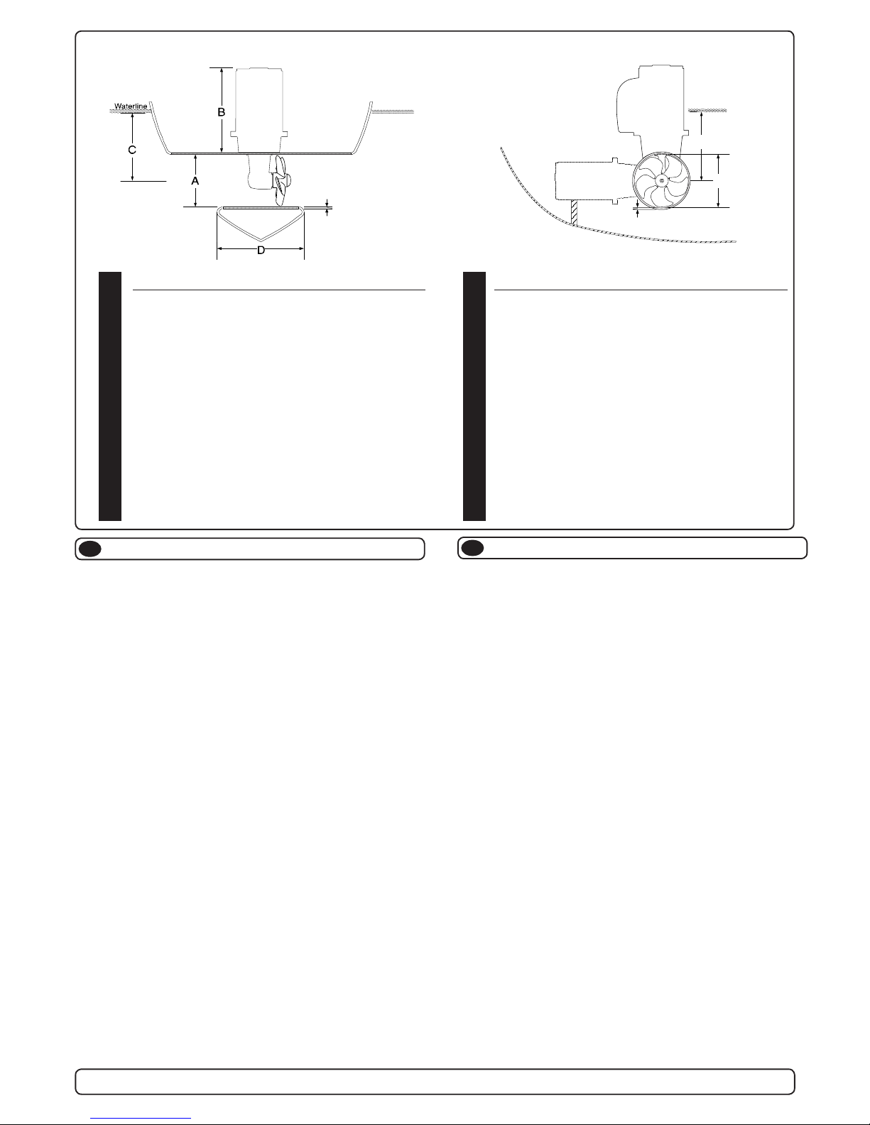
C
Waterline
A
F
SEP40/125S SEP60/185S
Thrust [lbs] 88 132
A [in] 4,92 7,28
B [in] 9,2 10,4
Cmin. [in] 4,92 5,91
D [in] 3,6 4,6
D recommended [mm] 7,25 9,2
Emin. [in] 0,16 0,16
Emax. [in] 0,20 0,24
Motor output [Hp] 3 4
Voltage [V] 12 12/24
Weight [lbs] 22 35
Note: Emin.: wall thickness of a standard Sidepower tunnel
Emax.: maximum wall thickness when using other GRP,
steel or aluminium tunnels
SEP40/125S SEP60/185S
Thrust [kg] 40 60
A [mm] 125 185
B [mm] 234 265
Cmin. [mm] 125 150
D [mm] 92 117
D recommended [mm] 184 234
Emin. [mm] 4 4
Emax. [mm] 5 6
Motor output [kW] 2,2 3,1
Voltage [V] 12 12/24
Weight [kg] 10 16
Note: Emin.: wall thickness of a standard Sidepower tunnel
Emax.: maximum wall thickness when using other GRP,
steel or aluminium tunnels
E
E

4
SEP 40/125 S - SEP 60/185 S 1.0 - 2012
Viktige forholdsregler og planlegning
N
Før installasjon må instruksjonsmanualen leses gjennom, og bruker må gjøre seg kjent med produktet.
Thrusteren må ikke installeres i rom som der gnister og høy varme medfører brannfare.
Elektromotoren vil produsere karbon støv fra børstene under drift slik att en lagringsplass må fysisk avskilles fra thrusteren for å unngå att det man
lagrer blir støvete / møkkete.
Elektromotoren er avhengig av god kjøling, sørg derfor for ventilasjon eller god plass rundt motoren ved montering.
Elektromotoren kan monteres i alle vinkeler i fra vertikalt til horisontalt der hvor plassutnyttelsen krever det.
Hvis elektromotoren monteres i en vinkel på mer en 30o, må den støttes opp separat.
Elektromotoren må håndteres forsiktig. Den må ikke bæres etter kontaktpunktene, og motoren må ikke settes ned på drivakselen.
Følg de anbefalte målene som er oppgitt i manualen, propell eller girhus må ikke stikke ut av tunnelen.
Elektromotoren, tilhørende komponenter, kontakter eller åpne ledd i strømkabler må monteres så de ikke utsettes for vann.
Vi anbefaler å male girhuset med bunnstoff. PS sinkanoder, pakninger og propellaksel skal ikke påføres bunnstoff.
Ikke påfør gelcoat / topcoat eller lignende inne i tunellen. Det er bare plass til ett lag primer og to lag bunnstoff mellom tunellen og propellene.
Når båten ligger på land har ikke elektromotoren den motstanden den har i vann. Motoren bruker derfor ekstremt kort tid før den oppnår ødeleggende
høyt turtall. Med båten på land, unngå hurtig bytte av driftsretning da det kan forårsake skade på truster.
Effektregulatoren PPC skal monteres vertikalt på et tørt og ventilert sted med kabeltilkoblingen nederst. Den skal monteres slik at batteri pluss-kabel
blir forgrenet på PPC, ikke på motoren.Det må være fritt rom rundt enheten, min 200mm over, og min 100mm foran og på sidene.Ta hensyn til at en
5m multikabel skal plugges inn mellom PPC og thrustermotor.
Denne manualen er beregnet som støttemateriell for montører med erfaring / utdanning, og har derfor ikke all informasjon nødvendig for å oppnå en
korrekt installasjon.
Installer ikke elektromotoren i nærheten av lett brennbart materiale, da motoren oppnår temperaturer over 100oC før den stopper automatisk.
Området intill thrusteren må ikke benyttes som lagringsplass da motoren vil bli varm samt att dette vil medføre en fare for att elektriske koblinger blir
løse eller kortslutter
I de tilfeller båter skal godkjennes eller klassiseres i henhold til internasjonal, eller spesielle standarder, er montør ansvarlig for at de gjeldende lover
og regelverk følges. Sleipner Motor AS kan ikke garantere at instruksjonene i denne manualen er i henhold til alle gjeldende regelverk og standarder.
NB ! Ved feilaktig installasjon av panel, thruster, PPC effektregulator eller tunnel frafaller all garanti stilt av Sleipner Motor AS.
Planning and important precautions
GB
Prior to installation, it is important that the installer reads this guide to ensure necessary acquaintance with this product.
The thruster must NOT be installed in compartments that require ignition proof electric equipment. If necessary, make a separate
compartment.
The electromotor will generate some carbon dust so that any storage compartment must be separated from the thruster to prevent the stored items
from becoming dusty/dirty.
If you are installing the Sidepower in a small room /compartment, it should be ventilated to ensure cooling of the electromotor.
If the height in the room you are installing the Sidepower is limited, the Sidepower can be installed horizontally or at any angle in between.
- If the electro motor is positioned more than 30° off vertical, it must be supported separately.
- The electromotor must be handled carefully. Do not lift it by the internal connections/main terminals or put it down on the driveshaft.
- Beware to keep installation within advised measurements. No part of the propeller or gearhouse must be outside the tunnel.
The electromotor, its components, contacts / plugs or other joints in the control cables must be mounted so that they will keep dry at all times.
We advice to paint the gearhouse and propellers with antifouling. PS! Do not paint the zinc anodes, sealings or propellershafts.
Do not nish the inside of the tunnel with a layer of gelcoat / topcoat or similar. It is only room for a thin layer of primer and two layers of
anti-fouling between the tunnel and the props.
With the boat on land, only run the thruster for a fraction of a second, as without resistance it will accelerate very fast to a damaging rpm.
Also, while the thruster is in air, make sure that the propellers have come to a complete stop before performing a directions change of the
thruster, as it might cause damage to the thruster.
The PPC Power control unit should be installed in a dry, ventilated place - cable connections facing down. Mount unit with battery positive cable
branching out at unit terminal, not at thruster motor. Allow free space at min 200mm over and min 100mm in front and at sides.Take into consideration
that a 5 m multicable shall be plugged in between thruster motor and PPC unit.
This manual is intended to support educated/experienced staff and is therefore not sufcient in all details for the correct installation.
Don’t install the electromotor at close range to easily ammable objects as it will reach over 100°C before the temperature switch is
activated.
Do not store items close to the thruster motor as it gets hot as well as any loose items near the thruster motor can cause problems with electrical wiring coming loose and short-circuiting.
When installed in boats approved or classied according to international or special national rules, the installer is responsible for following the demands
in accordance with these regulations / classication rules. The instructions in this guide can not be guaranteed to comply with all
different regulations/classication rules.
These instructions are only general instruction. If you are not skilled to do this work, please contact professional installers for assistance.
NB! Faulty installation of the tunnel, thruster, PPC Power Control unit or panel will render all warranty given by Sleipner Motor AS void.
5
SEP 40/125 S - SEP 60/185 S 1.0 - 2012
Plassering av tunnel og thruster
N
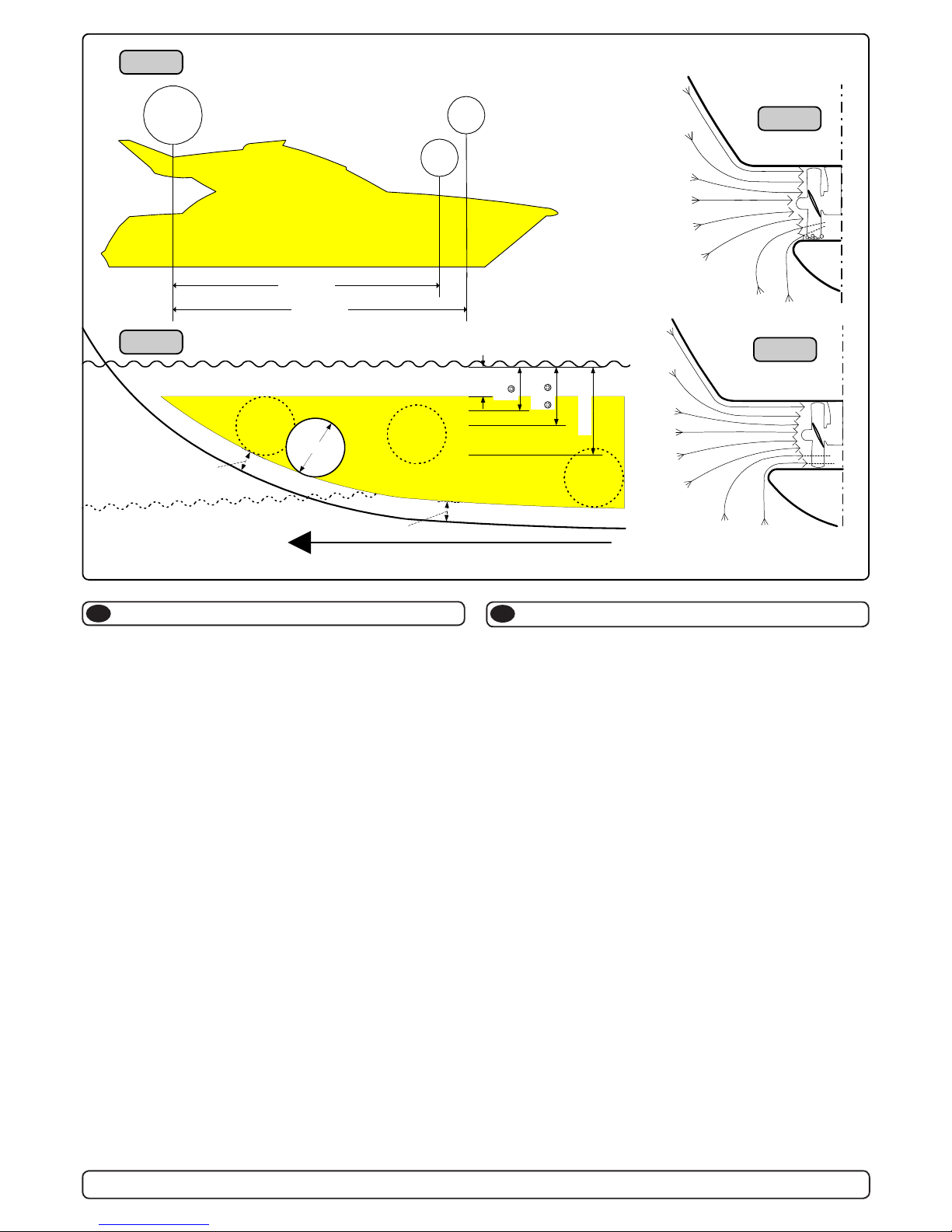
Tunnelen bør plasseres lengst mulig frem i baugen (Fig. 1)
For å oppnå mest mulig moment rundt båtens dreiepunkt, er det meget
viktig å plassere tunnelen så langt fremme som mulig. Avstanden fra
båtens dreiepunkt til thruster vil ha stor betydning på thrusterens effekt.
Eks.:
A: 55kg skyvekraft x 11m moment = 605kgm skyvekraft
B: 55kg skyvekraft x 10m moment = 550kgm skyvekraft
Posisjon A vil gi 10% mer skyvekraft til rotasjon.
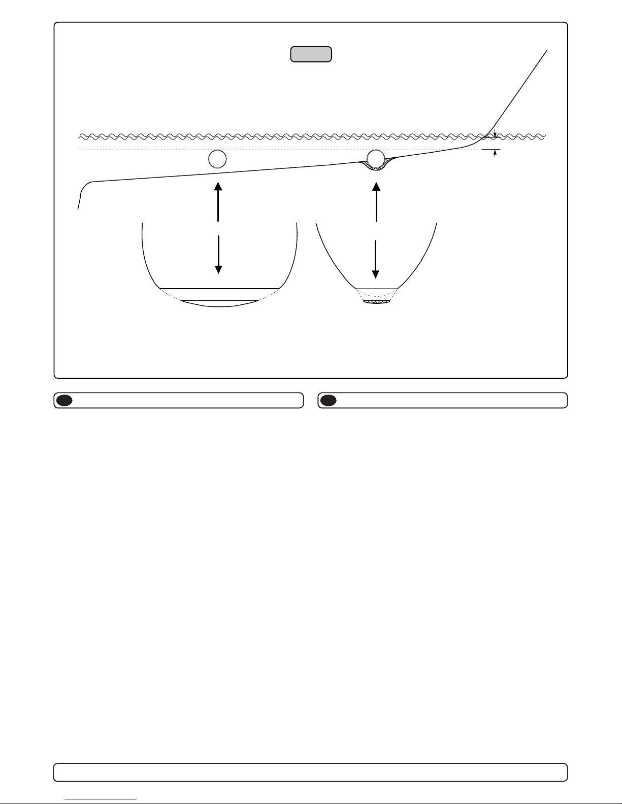
Tunnelen skal plasseres dypest mulig (Fig. 2)
Tunnelen skal plasseres så dypt som mulig av to grunner:
1. Så luft ikke suges ned i tunnelen å ødelegger skyvekraften.
2. Ved å øke vanntrykket jobber propellen mer effektivt.
Hovedregelen er at tunnelen skal plasseres minimum ½ x tunnelen dia.
under vannlinje. Anbefalt dybde er minst ¾ x dia. under vannlinje (). Når
tunnelen er plassert 33-35 cm under vannlinjen bør andre faktorer vur-
deres som viktigere, d.v.s. å plassere tunnelen lengre frem.
Optimal tunnel lengde
Dersom tunellen blir for lang vil friksjonen i tunellen reduser vannhastigheten og derved effekten.
Dersom tunellen blir for kort (normalt bare i nedre del av tunellen) kan det
oppstå kavitasjons problemer da vannet ikke har tid / av-stand til å «rette
opp strømningsretningen» før det treffer propellen (Fig. 3&4). Denne
kavitasjonen vil redusere effekten og lage mye støy.
Den optimale tunell lengden er 2 til 4 ganger tunell diameteren og dersom
tunellen blir så mye som 6 til 7 ganger diameteren i lengde vil effekt tapet
bli klart merkbart.
Positioning of the tunnel / thruster
GB
The Thruster should be as far forward as possible (Fig. 1)
Because of the leverage effect around the boats pivot point, it is very
important for the thrusters actual effect in the boat to get it as far for-ward
as possible. The relative distance change from the boats pivot point to the
thruster will be the change of actual thrust for the boat.
Example:
A: 55kg thrust x 11m leverage = 605kgm torque to rotate the boat
B: 55kg thrust x 10m leverage = 550kgm torque to rotate the boat
In position A you will get 10% more thrust to turn the boat around.
The thruster should be placed as deep as possible (Fig. 2)
The tunnel should be placed as deep as possible for two reasons:
1. So that it does not suck down air from the surface which will
destroy the thrust completely.
2. To get as high as possible a water pressure to get maximum
efciency from the propeller.
Generally the top of the tunnel should be a minimum of ½ x the tunnel
diameter below the waterline. This is an absolute minimum and we recommend that it is at least ¾ x tunnel diameter () below the waterline.
A really good distance is about 1/1 x tunnel diameter () below the
waterline.
When you get the top of the tunnel 30-35 cm*/1 feet below the surface,
other factors should be considered more important, i.e. moving the thruster further forward.
Optimal tunnel length
If the tunnel gets to long, the friction inside will reduce the water speed
and thereby the thrust.
If the tunnel gets to short (normally only in the bottom section of the tunnel) you can get cavitation problems as the water will not have had time to
“straighten” itself before reaching the propeller (Fig. 3&4). This cavitation
will reduce performance as well as creating a lot of noise.
The optimal tunnel length is 2 to 4 x tunnel diameter and you should avoid
tunnels longer than 6 to 7 times the tunnel diameter as the performance
reduction is then clearly noticeable.
A = 11,0m
B = 10,0m
A
B
Pivot
point
m
i
n
.
1
/
3
Ø
Ø
m
i
n
.
1
/
3
Ø
3/4Ø
☺
1/1 Ø
☺
☺
30 - 35 cm*
min.
1/2Ø
Fig. 1
Fig. 2
Fig. 3
Fig. 4
6
SEP 40/125 S - SEP 60/185 S 1.0 - 2012
Tunnelåpninger
N
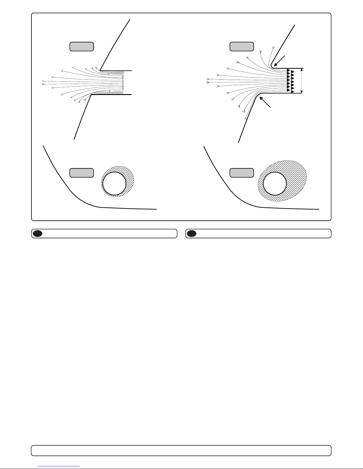
Avrundede åpninger vil minke støy, og maksimere effekt.
Vi anbefaler å avrunde tunnelåpningene mest mulig.
Den optimale avrundingen har en radie som er 10% av tunnelens diameter.
Hvorfor er en avrundet tunnelåpning så viktig?
1. En avrundet tunnelåpning vil forhindre at det oppstår turbulens / kavi-
tasjon, noe som vil oppstå ved en installasjon med skarpe kanter.
Turbulensen forårsaker mer støy, og begrenser skyvekraften.
- Turbulensen / kavitasjonen blokkerer tunnelen og svekker skyvekraften.
- I det kavitasjon og turbulens når propellen påvirkes ytelsen til denne
og øker støyen.
2. En avrundet tunnelåpning gjør også at thrusteren suger vann langs
skroget på båten. Dermed oppstår det et lavtrykk som vil hjelpe å suge
båten i dreieretningen. Med skarpe åpninger klarer ikke thrusteren å
suge vann langs skroget, og lavtrykket uteblir. Så mye som 40% av
skyvekraften har blitt målt til å ligge her på noen installasjoner.
NB! Propellene til Sidepower thrustere kaviterer ikke på arbeids-has-
tighet, så kavitasjon og støy som oppstår som følge av kavitasjon,
skapes av tunnel installasjonen.
NB! Selv der en perfekt avrunding ikke er mulig er det viktig å runde av
kantene så mye som mulig, en tunnelåpning med skråkant vil ha
stor effekt fremfor en med skarpkant (se side 20, ill. 1b & 1d).
Tunnel ends
GB
Rounded tunnel ends will maximize thrust and minimize noise.
We recommend rounding the tunnel connection to the hull-side as
much as possible.
The optimum rounding has a radius of 10% of the tunnels diameter.
Important advantages over sharp tunnel to hull connections are:
1. The rounded tunnel end will prevent creation of turbulence
cavitation that will come from a sharp tunnel end when water
passes by fast, thereby preventing a double negative impact on
the thrust and noise level (Fig. 1 & 2).
- The turbulence / cavitation blocks the outer area of the tunnel
and thereby reduces the effective tunnel diameter and thrust.
- The turbulence / cavitation hits the propeller and thereby reduce
the propellers performance and creates noise.
2. The curved tunnel end makes the thruster take water also from
along the hull-side, creating a vacuum that will suck the boat
sideways and thereby give additional thrust (Fig. 3 & 4).
With a sharp tunnel end, the thruster will be unable to take water
from along the hull-side, and you will not get the desired vacuum
and additional thrust. This “free” additional thrust can in optimal
installations be as much as 30 - 40% of the total thrust.
NB! A Sidepower thruster propeller does not cavitate at working
speed so that all cavitation and cavitation noise in the tunnel will
be caused by the tunnel installation.
NB! Even if it is not possible to make the perfect rounding, it is very
important to round the tunnel end as much as possible. A
angled tunnel to hull connection will also do much of the same
job as a rounded connection (see page 20, Fig. 1b & 1d).
☺☺
☺☺
☺
��
��
�
Fig. 2
Fig. 4
Fig. 1
Fig. 3
R = 0,1 x D (10%)
R = 0,1 x D (10%)
D
7
SEP 40/125 S - SEP 60/185 S 1.0 - 2012
Motstand forårsaket av tunnel
Prevent drag from tunnel
N
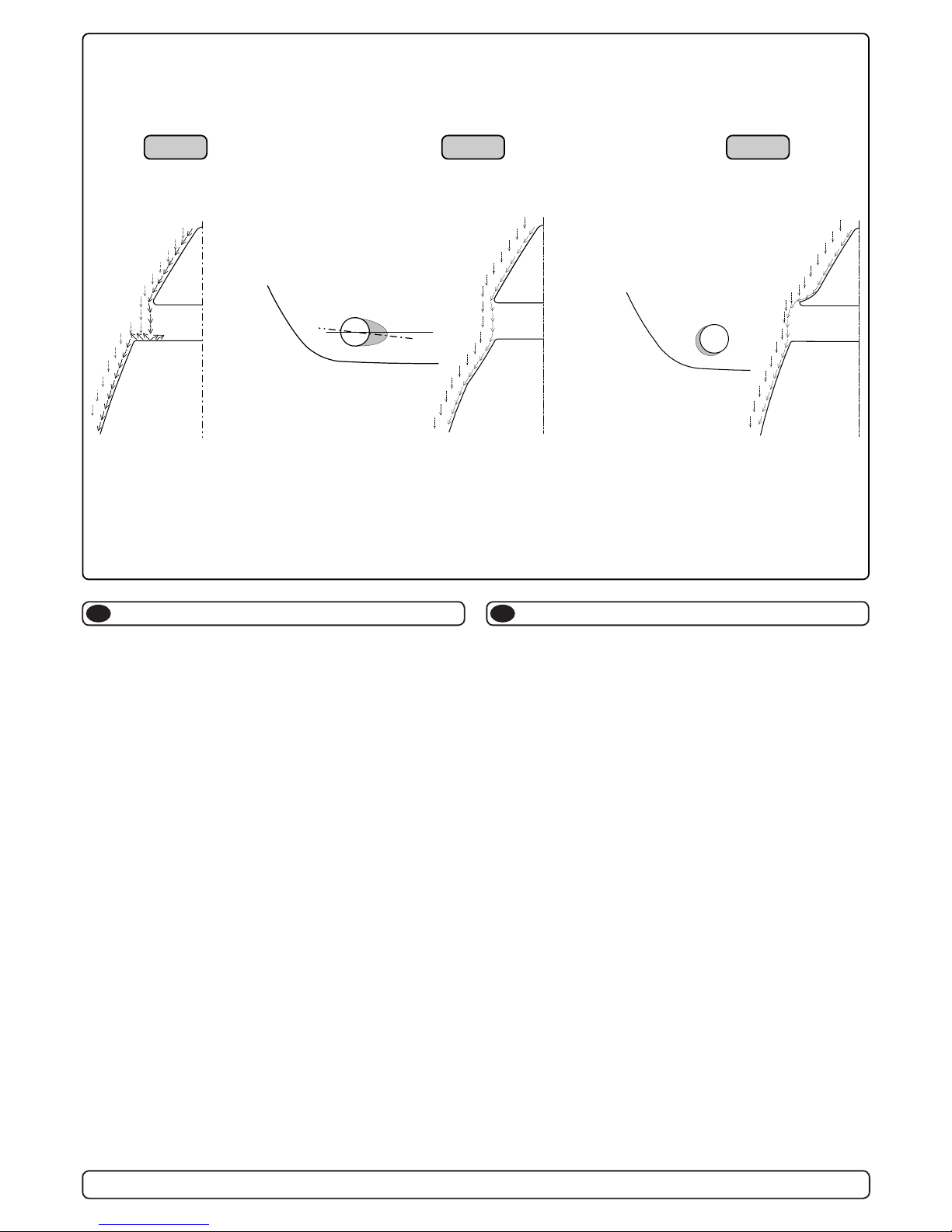
Et mulig problem for seilbåter eller meget hurtiggående båter er motstand
i tunnelen. Aktre ende på tunnelen vil være en liten loddrett ate mot
vannstrømmen som skaper uønsket motstand.
Denne aten kan også forårsake problemer med at vann føres inn i tunnelen under seilas, eller kjøring i høy fart og får da propellen til å rotere,
dette skaper uønsket støy.
Det er to mulige løsninger på problemet, avhengig av hva som er enklest
å få til på båten.
1. Den løsningen som vanligvis reduserer motstanden mest er å lage
en fordypning i skroget i aktre ende av tunnelåpningen. Den loddrette
aten vil da forsvinne og dermed motstanden. Hovedregelen å følge
er at bakkanten av tunnelen ikke skal synes når man står rett foran
båten å titter akterover langs båten senterlinje. Dybden, utformingen
og vinkling av fordypningen avhenger av båttypen, og hvordan vannet
følger skroget, men de este båter vil være tjent en fordypning som
vinkler lett nedover (Fig. 2).
2. Motstanden vil også reduseres av en spoiler i forkant av tunnelen.
Spoileren fører det meste av vannstrømmen rundt og forbi tunnelen.
Størrelsen og utformingen på spoileren avhenger av båten. Hovedregelen er at bakkanten av tunnelen ikke skal synes når man står
rett foran båten å titter akterover langs båten senterlinje. Den enkleste
måten å lage spoileren på er å la tunnelen stikke ut i forkant av tunnelen, og forme spoileren opp mot den (Fig. 3).
Det er alltid viktig å avrunde tunnelåpningene mest mulig for å motvirke
støy og for å få mest mulig effekt av thrusteren.
Mer informasjon om dette på side 10.
GB
A possible problem in sailboats or fast powerboats is that they get a
drag from the back face of the tunnel, as this becomes a “at” area
facing the water ow (Fig. 1).
This can also create problems with the thruster spinning (passive)
and making noise while sailing or driving the boat with water being
pushed through the tunnel at high speed.
This can be solved in two different ways, depending on what is
possible or easier to do.
1. The best solution which normally reduces the drag most is to make
a recess in the hull at the back of the tunnel. Thereby the back face
is gone and about all the drag (Fig. 2). The depth and shape of this
recess will depend on the boat. Basically you should not see the back
face of the tunnel when standing directly in front of the tunnel at the
angle of the boats centreline. The angle up or down backwards of the
insert in the hull, depends on the hull shape, but normally it is angled
slightly down because of the water ow on this area of the hull.
2. The drag will also be reduced a lot, especially in fast power boats, by
making a deector / spoiler in front of the tunnel. This will push the
water ow out from the hull so that most of it passes by the back face
of the tunnel (Fig. 3).
The shape and size of this deector will depend on the hull shape.
Basically you should not see the back face of the tunnel when standing
directly in front of the tunnel at the angle of the boats centreline. The
easiest way of making this is to let a part of the tunnel stick out in the
lower forward area of the hole, and use this as a support to mould a
soft curve/spoiler shape.
Remember to still round the tunnel ends as much as possible to get
optimum thruster performance and minimum noise. For more
information on how to practically do this see page 10.
☺☺
☺☺
☺
��
��
�
Fig. 2Fig. 1 Fig. 3
☺☺
☺☺
☺
8
SEP 40/125 S - SEP 60/185 S 1.0 - 2012
Tunnel installasjon på seilbåter
N
Mange seilbåtskrog er bygget for å oppnå høy fart. De har brede skrog
som ikke stikker dypt i baugen. Skrogtypen gjør det vanskelig å installere
en thrustertunnel på vanlig måte, spesielt med tanke på å plassere den
langt nok frem (Fig. 1).
Thrustertunneler kan allikevel installeres i de este seilbåter. Dette gjøres
ved å la en del av tunnelen stikke ut i underkant av skroget. Tunnelen er
sterk nok til dette, og thrusteren blir plassert lav nok og langt nok fremme.
Dette gjøres ved at øvre halvdel av tunnelen støpes inn i skroget, tunnelen styrkes i underkant ved å støpe en kul rundt tunnelen og jevne den ut
mest mulig.
Denne metoden brukes av noen av de helt største seilbåt-produsentene i
verden, de viser til at den ikke gir utslag på fart under normal seilas.
Denne installasjonen kan også være gunstig for båter med ate bunner,
for å unngå ekstremt lange tunneler og store ovale tunnelåpninger.
Tunnel installation in sailboats
GB
Many sailboats have a racing type hull which means that it is very at bottomed and has a very shallow draft in the bow section. It is thereby very
difcult not to say impossible to t a tunnel thruster the usual way, at least
as far forward in the hull as a thruster should be (Fig. 1).
However, it is possible to install a tunnel thruster in most sailboats, even
when the hull does not directly support the tting of a tunnel.
This is done by tting the tunnel halfway into and halfway under-neath the
existing hull and then strengthen it and smoothening the water ow by
moulding a bulb around / underneath the tunnel.
This will allow installation in good position on the boat, maintaining the
reliability and space advantages of a tunnel thruster.
This installation is being used by some of the world’s largest sailboat
builders, and has been proven to give little to no speed loss for normal
cruising.
This can also be a good installation method for at bottomed barges to
avoid extremely long tunnels and huge oval tunnel openings in the hull.
Fig. 1
Min
��
��
�
☺☺
☺☺
☺
Pos. B
Pos. A
��
��
�
☺☺
☺☺
☺
9
SEP 40/125 S - SEP 60/185 S 1.0 - 2012
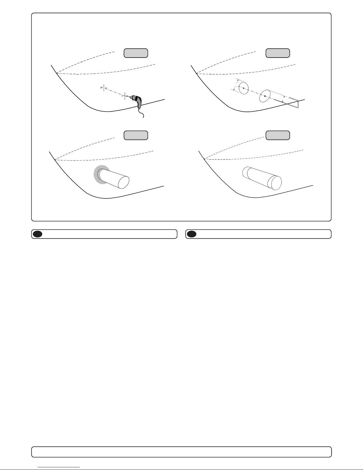
Tunnel installering
N
Sleipner Motor anbefaler at innstøping av glassbertunnelen utføres
av kyndig personell. Denne instruksjons manualen gir ikke detaljerte
opplysninger om glassberstøpning. Problemer som skyldes installering er installatørens fulle ansvar.
Bestem plassering av tunnelen ut i fra informasjonen gitt tidligere i manualen, og de angitte mål for thrusteren du skal installere.
Merk av senter på tunnelen på babord og styrbord side. Bor et 6 m.m.
vannrett hull, på begge sider (Fig. 1).
Bøy til og tilpass en 5 m.m. stålstang, som vist på g. 2 der den tilbakebøyde enden skal markere tunnelens radius. Stikk enden inn å marker
tunnelens ytre diameter, skjær ut hullet med en stikksag (Fig. 2).
Puss av gelcoat og polyester så glassberen ligger bar i et 12 cm stort
område rundt tunnel hullet. Dette må gjøres på innsiden og utsiden av
skroget, før tunnelen støpes fast i skroget (Fig. 3).
Sett inn tunnelen å marker hvor det skal kappes for å passe i skroget
(Fig. 4). Hvis det skal støpes en spoiler i forkant av tunnelen bør en del av
tunnelen stikke ut i for og underkant av skroget for å støpe spoileren mot
(Side 20, Fig. 2). Kapp tunnelen i ønsket størrelse. Slip lett med slipepa-
pir, og vask med aceton der hvor det skal støpes med glassber.
NB ! Det må ikke støpes der hvor thrusteren skal monteres.
Støp fast tunnelen først på innsiden av skroget, bruk minst 8 lag med 300
g Glassbermatte, og polyester. Ved bruk av alternative materialer, glassber matter eller rovingtyper (Se s. 20, Fig. 1). Hvis tunnelåpningene
avrundes til den optimale 10% radius må ofte legge ekstra lag med polyes-
ter glassbermatte på innersiden av tunnelen, for å oppnå riktig tykkelse i
forhold til skrogtykkelsen.
NB ! Forsikre deg om at overgangene mellom tunel og skrog er nøye
sammenstøpt. På steder en ikke kommer til med vanlige lag med polyes-
ter/glassber matte, sørg for og lage en blanding av polyester og glassber, som fylles i dette.
Tunnel installation
R
D
Fig. 1
Fig. 3
Fig. 4
Fig. 2
GB
We recommend that a professional does the breglass tting of the
tunnel. These instructions are only general, and do not explain in
any way the details of breglass work. Problems caused by faulty
installation of the tunnel, are the installers full responsibility.
Find the position in the boat considering the information given earlier in
this manual and the applicable measurements for the thruster model you
are installing.
Mark the centre of the tunnel on both sides. Drill a 6mm hole horizontally
in these marks (Fig. 1).
Bend a ø 5mm steel bar as shown with the “tip” bent back at the tunnel
radius and mark the circle for the tunnel opening (outside diameter of the
tunnel). Cut the hole with a jigsaw (Fig. 2).
Grind off the gelcoat and polyester so that you are down in the “real bre-
glass” in an area of 12cm around the hole both inside and outside in the
hull to cast the tunnel to the hull (Fig. 3).
Insert the tunnel and mark its shape to t the hull (Fig. 4). (if you are installing with a deector/spoiler, leave a part or the tunnel of the front- and
underside of the tunnel to have a base for this (see page 20, Fig. 2). Cut
the tunnel ends to the desired shape and lightly sand its surface and
clean with acetone or similar where you are going to apply breglass.
NB! Do not cast/glass on the area were the thruster will be placed.
Then cast the tunnel to the inside of the hull, use at least 8 layers of 300 g
glass and resin, preferably alternating mat and rowing types of breglass
(see page 20, Fig. 1). If you are rounding the tunnel ends to the perfect
10% radius you may in some cases have to make further layers inside to
preserve the desired hull thickness.
NB! Make sure that any gap between the tunnel and the hull are com-
pletely lled with resin/breglass. In areas where you can not access to
make normal layers of resin/breglass, a resin/ breglass mixture must be
lled in that area.

10
SEP 40/125 S - SEP 60/185 S 1.0 - 2012
Tunnel installeringTunnel installation
N
Rund av tunnelendene med en radius 10% av tunneldiameter (Fig. 1a),
eller lag en skråkant 10-15% av tunneldiameter (Fig. 1c). Der dette ikke er
mulig skal tunnel kantene rundes av mest mulig.
Vi anbefaler å støpe to lag utenpå tunnellavrundingen og over et område
på 6-8cm (Fig. 1c & 1d).
Gelcoat eller lignende må påføres på områdene der det har blitt pusset
eller støpt for å gjøre glassberen vanntett.
NB ! Alle originale Sidepower tunneler er vanntette ved levering!
Så fremt man ikke ønsker en annen farge er det ikke nødvendig å påføre
Gelkoat, Topkoat og ere lag med primer for å gjøre tunnelen vanntett.
Puss tunnelen med nt slipepapir og påfør et lag primer for å få bunnstoff
til å sitte.
Sidepowertunnelen er helt vanntett uten behandling med unntak av de
områder det som er støpt fast i skroget.
Påfør Gelcoat/Topcoat/epoxy og primer på de områder som er pusset ned
eller støpt. Vann skal ikke ha direkte kontakt med glassberen i skroget
fordi dette normalt ikke er vanntett.
PS ! Det må ikke støpes der brakketen til thrusteren skal stå. Pass-
formen er nøyaktig tilpasset, og en feilplassert braket kan forårsake svikt i girhus.
GB
Soften the edges with a radius of 10% of the tunnel diameter (Fig. 1a) or
make a slope with a length of 10-15% of the tunnel diameter (Fig. 1c). If
this is not possible, at least round the tunnel end as much as possible.
We advice to also cast two layers on the outside of the tunnel/hull for an
6-8cm area (Fig. 1c & 1d).
You must apply topcoat/epoxy on the areas outside where you have
grounded or moulded to again make these waterproof.
NB! All original Sidepower tunnels are fully waterproof when
they are delivered.
This means that unless you want, because of special reasons, to have another colour on it, you do not have to apply topcoat or the several layers
of primer that is necessary on the boats’ hull to make it water-resistant.
Sand it very lightly and apply one layer of primer to make the antifouling
sit.
The original Sidepower tube itself is fully water-resistant without treatment
except in the areas where you have bonded it to the hull.
Apply topcoat/epoxy paint and primer on the areas where you have
grounded or moulded as these areas give the water access to the hull
which normally is not waterproof without these applications outside.
PS! Avoid all casting where the motor-bracket is to be placed,
as this will cause mist and possible failure of the
gearhouse.
R = D x 0,1
R = D x 0,1
D
x
0
,
1
-
0
,
1
5
D
x
0
,
1
-
0
,
1
5
D
Fig. 1a
Fig. 1
Fig. 1b
Fig. 2
Fig. 3
Fig. 1d
Fig. 1c

11
SEP 40/125 S - SEP 60/185 S 1.0 - 2012
Montering av girhus og brakett
N
Fitting gearhouse and motor bracket
GB
Fig. 5
Fig. 3
Bolt tightening forces (2x):
DIN 931 - M 8x55 A2 =
17 Nm (12,4 lb/ft)
Fig. 6
Fig. 1
Fig. 5
A
Fig. 2
SP30S2i
SP40S2i
Fig. 3
SP55S2i
20,5mm
0,81"
Ø 8,5mm
0,33"
TUNNELS
CENTRELINE
BOAT S
CENTRELINE
Ø 27,5mm
1,08"
BOW
23,0mm
0,91"
Ø 8,5mm
0,33"
TUNNELS
CENTRELINE
BOATS
CENTRELINE
Ø 28,5mm
1,1"
BOW
Port Starboard
Fig. 7
G
E
A
R
O
I
L
E
P
9
0
S
L
E
I
P
N
E
R
3
4
1
2
A
Fig. 4
Bolt tightening forces (2x):
DIN 931 - M 8x55 A2 =
17 Nm (12,4 lb/ft)
G
E
A
R
O
I
L
E
P
9
0
S
L
E
I
P
N
E
R
3
4
1
2
A
Bolt tightening forces (2x):
DIN 931 - M 8x55 A2 =
17 Nm (12,4 lb/ft)
G
E
A
R
O
I
L
E
P
9
0
S
L
E
I
P
N
E
R
3
4
1
2
A
1. Mark the centreline of the tunnel and the boats centreline. The
gearhouse and propeller must be tted as shown above for the
thrust direction to correspond with the control panel (Fig. 1).
2. Use the gasket (A) to mark the centre of the holes and double
check the measurements. NB! The thruster should be placed
with the bolt hole as the centre (Fig. 2a/2b). All holes must be
in-line with the tunnels’ centreline for precise installation, as
the clearance between the propeller and the tunnel is minimal.
3. There must be no casting where the motor bracket is to be
placed, as this will cause possible failure of the gearhouse.
The motor bracket must t steady on the tunnel, if the tunnel is
not smooth, all bumps or uneven parts must be grinded
smooth.
4. Drill the main-hole and then the two screw-holes.
5. Try the lower-unit in the tunnel (without the propeller) by using
the gasket inside the tunnel. Try on the propeller to make sure
it is in the middle of the tunnel and turns freely with the same
clearing from each blade to the tunnel. Use sealant e.g.
Sikaex to ensure that no leakages occur.
6. Push the gearhouse through the main hole in the tunnel and
push the gearhouse and motor-bracket gently together.
7. Screw the lower unit and the motor-bracket together with the
two provided bolts. Tighten with 17 Nm / 12,4 lb/ft.
8. Use the enclosed template to measure that the driveshaft has
come through the motorbracket with the correct height (Fig. 5).
1. For å plassere girhuset riktig må du først markere tunnelens,
og båtens senterlinje på tunnelen. Propellen og girhuset må
plasseres i henhold til g. 1 ovenfor for at styreretning og kjø-
reretning skal korrespondere
2. Bruk pakningen til å markere midten av hullet (A) og for å dob-
beltsjekke målene.
NB ! Thrusteren skal plasseres med boltehullet som senterlin-
jen i midten av båten (Fig. 2a/2b). Alle hull må være på tunnelens senterlinje for å får til en presis installasjon. Dette skyldes
at det er meget liten klaring mellom tunnelveggen og propellen.
3. Tunnelen må ha en jevn overate der braketen skal festes,
all støp, evt glassber eller epoxy rester må pusses ned så
braketen passer jevnt på tunnelen. Ujevnheter her vil kunne
resultere i skade girhuset.
4. Bor de to boltehullene, og hovedhullet til girhuset.
5. Prøv girhuset i tunnelen sammen med pakning 1m.m. Monter
propell å sjekk at den er i midten av tunnelen. Hvis tunnelen
ikke har en jevn overate så kan Sikaeks, eller lignende tetningsmateriale brukes for å sikre mot lekkasje.
6. Før girhuset gjennom hovedhullet i tunnelen og monter bra-
ketten og girhuset forsiktig sammen.
7. Skru sammen motorbraketten og girhuset med orginalbolter.
Skru til med moment 17 Nm / 12,4 lb/ft.
8. Bruk den inkluderte distansebrikken for å sjekke at drivakselen stikker opp av braketten i riktig høyde (Fig. 5).
Fig. 2a
SEP40/125S
Fig. 2b
SEP60/185S

12
SEP 40/125 S - SEP 60/185 S 1.0 - 2012
Montering av propell
N
1. SEP40/125S:
Trykk propellen på akslingen, påse at spline i propeller passer på
spline på aksling.
SEP60/185S:
Vri propellakselen så drivpinnen (5) står loddrett. Pinnen må stå midt i
propellakselen.
2. Vri propellen så sporet for driv pinnen er loddrett, eller i lik vinkel som
du har stilt drivpinnen. Skyv propellen inn på propellakselen. Det skal
nesten ikke være klaring mellom propellen og girhuset.
3. Sett på skiven (4) på propellakselen, deretter strammes låsemutteren
(3).
4. Plasser anoden (2) i sporet sitt. Fest den med skruen til anoden (1).
Bruk locktight eller lignende for at skruen ikke skal skrus ut av propellrotasjonen.
Delebeskrivelse:
1: Skrue til anode
2: Anode
3: Låsemutter til propell
4: Skive til propell
5: Drivpinne for propell
Fitting propeller
GB
1. SEP40/125S:
Push the propeller on to the shaft and turn until the internal
spline in the propeller hub aligns with the external spline on
the propeller shaft.
SEP60/185S:
Push the propeller onto the shaft, carefully rotate the propeller
until the drive pin (5) aligns and moves into the slot/grove in the
propeller hub. There should be almost no gap (approximately
1mm) between the propeller hub and the gear house.
2. Place the washer (4) on the propeller shaft and then tighten the
lock-nut (3) on the propeller shaft.
3. Place the anode (2) in its designated position and tighten the
anodes holding screw (1). Apply a thread glue (Locktite or
similar) to ensure that the anodes holding screw does not un screw itself from the propellers rotation.
Parts description:
1: Screw for anode
2: Anode
3: Propeller lock nut
4: Washer
5: Drive pin for propeller
5
34
1
2
Locktite
SEP60/185S
1
Locktite
2
34
SEP40/125S

13
SEP 40/125 S - SEP 60/185 S 1.0 - 2012
Fig. 1
Fig. 2
Montering av elektromotor
N
Fitting the electromotor
GB
Bolt tightening force (M 8):
17 Nm (12,4 lb/ft)
1. Turn the driveshaft in the gearhouse and the motor shaft so that
the track for the shear pin has a corresponding direction with the
shear pin in the motor shaft.
2. Slide the motor gently onto the driveshaft and motor bracket. You
might have to jiggle it a bit to get it on as the tting is tight. The
electromotor can sit in all directions on the bracket. Ensure that
the cable terminals are available for electric installation later.
3. Fasten the motor loosely to the bracket with the provided bolts.
4. If you are installing the motor in an angle of more than 30° off a
vertical position, the electromotor needs a separate/additional
support. See illustration in the measurements drawings.
5. Tighten the bolts holding the motor to the motorbracket with
17Nm /12,4 lb/ft as shown in Fig. 1.
6. Check the drive system by turning the propeller, it will be a little
hard to turn (because of the gear reduction and the motor), but
you should easily be able to turn it by hand.
In some cases (shallow installation or workboat/shing boat only) we
recommend to protect the propeller by mounting a grid in the tunnel opening (Fig. 2). It is important to keep a grid to a minimum and as streamlined
for the thrusters waterow as possible, as it will decrease the effect of the
thruster. Do not circular prole steel as it will decrease thrust signicantly.
NB! Paint the gearhouse and propeller with antifouling made for
propellers. Do not paint the propeller shaft, the zinc anodes or
the end face of the gearhouse.
NB! Do not run the thruster for more than very short bursts without
being in the water.
NB! If the boat is still being built when the electromotor is installed,
it must be covered up to avoid dust from the building going into
the motor and the solenoids. This cover must be removed before the
thruster is being used.
1. Vri drivakselen i girhuset og akslelen i elektromotoren så sporet for
brytepinnen i drivakselen korresponderer med brytepinnen i motor
akselen.
2. Sett motoren forsiktig ned på motorbraketten og drivakselen. P.g.a.
nøyaktig tilpasning kan det være vanskelig å treffe sporet for brytepinnen med brytepinnen. Elektromotoren kan stå i alle retninger på
brakketen.
3. Fest motoren løst til braketten med bolter.
4. Hvis motoren er vinklet med mer en 30° trenger motoren separat
oppstøtting.
5. Stram boltene med 17Nm/12,4 lb/ft som vist i g. 1.
6. Sjekk systemet ved å vri på propellen. P.g.a. utvekslingen i gir-huset
vil dette være tungt, men det skal være mulig å vri den for hånd.
I visse tilfeller (ved grunne installasjoner, ske/arbeidsfartøy fartøy)
anbefaler vi å beskytte propell og girhus ved å montere et gitter foran
tunnelåpningene (Fig. 2). Det er da meget viktig å beholde strømlinjeformen, og å begrense gitteret til et minimum. Feil installasjon kan begrense
skyvekraften med 10%.
NB ! Påfør bunnstoff på girhus og propell for å unngå vekst som kan
svekke thrusterens effekt. Sinkanoder propellaksling og tetninger skal ikke
stoffes.
NB ! Thrusteren må kun kjøres i meget korte perioder når den ligger på
land.
NB ! Hvis båten fortsatt er under bygging når thrusteren blir montert må
motoren dekkes til for å unngå at støv og lignende trenger inn i girhus og
elektromotor. Dekket må fjernes før motoren tas i bruk.

14
SEP 40/125 S - SEP 60/185 S 1.0 - 2012
SEP60/185S 12 V 340 A DIN: 350
SAE:665
mm
2
AWG
35 150
1/0
60
2/0
95
3/0
95
3/0
2x 70
2x 2/0
120
4/0
2x95
2x 3/0
2x 95
2x 3/0
2x120
2x 4/0
2x120
2x 4/0
280*
24 V 170 A DIN: 175
SAE: 332
mm
2
AWG
25 135 125
1
35 125
1
35 135
1
50
1/0
50
1/0
60
2/0
60
2/0
70
2/0
SEP40/125S 12 V 280 A DIN: 300
SAE: 570
mm
2
AWG
35 150
1/0
50
1/0
70
2/0
95
3/0
120
4/0
120
4/0
2x95
2x 3/0
2x95
2x 3/0
2x120
2x 4/0
2x120
2x 4/0
260*
Minimum and recommended cable dimensions can be identical due to safety margins and cable heat considerations for short cable lenghts.
* Minimum or recommended cable cross section in mm
2
Battery & cable recommendations:
Elektrisk installasjon
N
• Forklaring til elektrisk tabell
- Kabellengder tilsvarer totallengden (A+B+C+D+E, Fig. 1).
- Min. batterikap. som kaldstartkapasitet (CCA), ikke Ampere.
- Bruk trege sikringer for å forebygge spenningsfall.
• Det er viktig å bruke kabler som er store nok, og et batteri med god
kaldstartkapasitet for å drive thrusteren. Det er spenninngen ( i volt)
som kommer frem til motoren under kjøring som bestemmer turtallet til
motoren og dermed også skyvekraften. Vær vennlig og jamfør listen
over for minimum anbefalte kabel, og batteristørrelse.
• En hovedstrømbryter som ikke medfører stor spenningsfall må in-
stalleres på thrusterens plusskabel. Det bør være mulig å skru av
strømmen til thruster uavhengig av resten av det elektriske systemet,
når man ikke er om bord, eller i et nødstilfelle. Bryteren bør plasseres
på et tilgjengelig sted, og båtens instruksmanual må ta for seg at denne
skal skrus av slik som de andre hovedbrytere.
• Det må installeres sikring på pluss strømkabelen for å beskytte mot
kortslutning av hovedstrømkablene. Sikringen bør være av høy kvalitet,
noe som vanligvis betyr at de er fysisk store, for å unngå spenningsfall
som ofte er resultatet av å bruke mindre, enklere sikringer. Sikringen
skal være en treg type som tåler amper trekket til elektromotoren i
minimum 5 min.
• Det anbefales å bruke Sidepower automatisk hovedstrømbryter
897712 (12V) eller 897724 (24V).Denne aktiveres når panel slås på,
og har også innebygget kortslutningsikring, samt en manuell nødstopp.Den gir også melding til panel ved evt. feil.
• Kabelendene kan må påmonteres terminaler og disse må isoleres mot
alt som ikke er riktig kontaktpunkt.
• Det er viktig att kabelsko trekkes korrekt fast på koblingsbolt. Kontra
mutter på koblingsbolt må holdes fast ved tiltrekking (Fig. 2).
SE40/125S: ø8mm / 5/16" bolt. Trekk til med 15 Nm / 11 lb/ft.
SE 60/185S: ø10mm / 3/8" bolt. Trekk til med 15 Nm/11lb/ft.
Electrical installation
GB
Fig. 1
Fig. 2
• Explanation of electrical table
- All cable lengths are the total of A+B+C+D+E in Fig. 1.
- Battery size is stated as minimum cold crank capacity, not Ah.
- Use slow fuse rated to hold stated Amp-Draw for min. 5 minutes.
• It is important that you use a good cable size and batteries with a
high cranking capacity to feed the thruster, because it is the actual
voltage at the motor while running the thruster that decides the
output rpm of the motor and thereby the actual thrust. Please see
the list below for advised min. sizes of cables and batteries. You can
of course use larger cables for even better results.
• A main switch that can take the load without noticeable voltage
drop must be installed in the main positive lead so the power for the
thruster can be turned off independent of the rest when not on board
or in emergencies. This should be placed in an easy accessible
place and the boats instructions should inform that this should be
turned off like the boat’s other main switches.
• We also advice to install a fuse in the positive lead for protection
against short circuiting of the main cables. This fuse should be of a
adequate quality which normally means that it is physically large as
these have less voltage drop than the simple / small ones. It should
be of the slow type and sized to take the amperage draw for at least
5 minutes.
• It is highly recommended to install a Sidepower Automatic Main
Switch 897712 (12V) eller 897724 (24V). The AMS will be activated
when the panel is turned on, contains an automatic short circuit
fuse and a manual emergency stop. The AMS will also provide
feedback to the panel regarding evt. faults.
• The cable ends must be tted with terminals and these must be well
isolated against contact with anything but the proper connection
point.
• Terminals must be properly tightened. Secure/hold inner nut when
tightening (Fig. 2).
SEP40/125S: ø8mm / 5/16" bolt. Tighten with 15 Nm / 11 lb/ft.
SEP60/185S: ø10mm / 3/8" bolt. Tighten with 15 Nm/11lb/ft.
Thruster
Battery
12/24V
Manual or
automatic
Main switch
Fuse
Proportional Power Controller P PC 800
190x300x145mm (w x h x d)
Thruster motor
5m fixed multicable
Min.
100mm
Min.
100mm
Min.
200mm
<5m
4X
PPC
A
B C
D
E
MOTOR
NB:
The Proportional Power Controller is a bulkhead
(wall) mounted unit and must be installed in a dry and
well ventilated compartment. The unit also requires
a 200 mm minimum head clearance and a 100 mm
minimum clearance surrounding its remaining outer
casing.
S-link control cables See page 15

15
SEP 40/125 S - SEP 60/185 S 1.0 - 2012
Wiring diagram
GB
N
Koblingsskjema elektrisk
+12/24V
-
5A
S-link on/off
switch
red
yellow
black
12/24V12/24V
Stern thruster
battery
Bow thruster
battery
Bow thruster
(SEP model)
Stern thruster
(SEP model)
-
black
+
red
B+
-
black
+
red
B+
Fixed multicable 5m
Fixed multicable 5m
5A
+12/24
5A
+12/24
PPC
PPC
Proportional
Power Controller
Proportional
Power Controller
PJC 212
Proportional
Joystick
Controlpanel
Station 1
Automatic Main Switch
8977 12 / 8977 24
or
Manual main switch
w/ANL fuse
Automatic Main Switch
8977 12 / 8977 24
or
Manual main switch
w/ANL fuse
S-link control system
End terminator
End terminator
Proportional
Joystick
Controlpanel
Station 2
PJC 212
Observe PPC battery
terminal polarity !
S-link supply
S-link external
switch interface
(optional)
Kontrollpanel og kontrollkabler
Kontrollpanel installasjon:
• Det er mulig å installere så mange kontrollpanel som ønskelig ved å
bruke Side-Power S-link T-stykker.
Hvis trusteren skulle motta signaler fra ere paneler samtidig, så kut-
ter den dersom signalene er til ulike retninger.Ved betjening til samme
retning vil det panel med størst stikke- pådrag bestemme trusterturtall.
• Ved bruk av Sidepower originalutstyr er alle elektriske kontakter klare til
å plugges i sammen.
• Hvis kjøreretningen ikke stemmer overens med forventningene må blå
og grå ledning på Thruster-releet byttes om.
• Monteringsveiledning for panelet følger panelet.
• Thrusterpanelet bør monteres et sted det er lett å bruke. Siden gass og
gir ofte brukes samtidigt som thrusteren, er det ofte en god løsning å ha
muligheten å operere disse med hver sin hånd.
N
Control panel and control-leads
GB
Control panel installation:
• You can install as many panels as you wish by using optional
Side-Power S-link T-connectors
If two or more panels are operated at the same
time in opposite directions, the thuster will stop. When two or more
panels is operated in the same direction, the thruster output will be
determined by the panel giving the largest signal.
• When using original Sidepower equipment it is all “plug & go”.
• If the drive direction of the thruster is the opposite of what
expected, the drive direction can be changed from the control panel
• The mechanical installation of the panel is described in the
manual following the panel.
• The thruster control should be placed in a position were it is easy
to use, and it is very common to use the thruster at the same
time as your gear/throttle lever so it is normally a user friendly
solution to be able to access these with one hand for each
control.

16
SEP 40/125 S - SEP 60/185 S 1.0 - 2012
Technical wiring diagram, thruster motor
GB
N
Koblingsskjema, trustermotor
A1
A2
D2
NTC
red
Thruster motor
D1
1234567
8
To PPC
B+
To PPC
M-
Multi cable to PPC
grey
blue
white
redpink
(Opt.)
8-way connector
C
C

17
SEP 40/125 S - SEP 60/185 S 1.0 - 2012
Signatur: ..................................................................................................
Dato: ........................................................................................................
Anbefalt før leverings test for installør / verft som ikke bruker andre
kvalitetskontrollsystemer!
Thrustertype: ...........................................................................................
Volt: ..........................................................................................................
Serienummer: ..........................................................................................
Leveringsdato: .........................................................................................
Korrekt kjøreretning per kontrollpanel: ....................................................
Spenning målt på thruster under kjøring: ................................................
Strømkabler: ............................................................................................
Skottet hvor thrusteren er montert er isolert fra kjølvann og har ingen
åpenbar risiko for lekkasje.
Kommentar fra installør:
Propellers is fastened correctly to the shaft.
Propellers turns freely in tunnel.
The zinc-anodes holding screw is tightened well with thread glue.
Anti-fouling have been applied to the gearhouse and propellers but
NOT on the zincanodes or the gearhouse lid where the propellers is
fastened.
Correct drive direction as per controlpanel.
All electrical connections are clean, dry and tight, and the correct
cable, fuse and main switch sizes have been used.
With a ohm meter check that there is no electrical connection
between electromotor body and positive terminal on the motor and
between the electromotor body and the negative (A1) terminal on
the motor.
The bolts holding the gearhouse and motorbracket together are
tightened correctly.
The bolts holding the electromotor to its bracket are tightened
correctly.
The 4 main cables connected to 3 terminals on PPC is placed cor-
rectly and properly xed to avoid mecanical stress on the terminals
Checklist
GB
The thruster has been installed as per the instructions in this manual and
all points in checklist above have been controlled.
Signed: ..................................................................................................
Date: .......................................................................................................
Extra pre-delivery tests by installer/yard who does not use other
quality control systems !
Thruster type: ........................................................................................
Voltage: ..................................................................................................
Serial number: .......................................................................................
Date of delivery: .....................................................................................
Correct drive direction as per control panel: ..........................................
Voltage at thruster when running: ..........................................................
Battery cable size used: ........................................................................
The compartment where the thruster is tted is isolated from general bilge
water and has no obvious or suspected risks for ooding.
Other comments by installer:
Sjekkliste
N
Propellene er festet til akselen på korrekt vis.
Propellene roterer fritt i tunnel.
Festeskruen til sinkanodene er festet med gjengelim.
Bunnstoff er påført girhus og propeller, men ikke på sinkanoder,
tetninger eller propellaksel.
Kontrollpanel gir korrekt kjøreretning på thrusteren.
Alle elektriske koblinger er rene, tørre og tette. Korrekte kabler,
sikringer og hovedstrømsbryter er brukt.
Boltene som festet brakett til girhus er festet korrekt.
Boltene som festet motor til brakett er festet korrekt.
De 4 hovedkablene tilkoblet 3 terminaler på PPC er korrekt plassert
samt klamret for å unngå mekanisk påkjenning av terminalene.
Thrusteren er installert i henhold til instuksene gitt i denne manualen, og
alle punkter i sjekklisten er kontrolert.

18
SEP 40/125 S - SEP 60/185 S 1.0 - 2012
Important user precautions
GB
• Forviss deg om at du kjenner plasseringen av hovedstrømsbryteren
til baugtrusteren og evt. hekktruster, som kutter all strøm til trusteren, slik at trusteren kan skrus av i nødstilfelle.
• Før berøring av noen del av trusteren må alltid strømmen skrus av.
En tilfeldig start kan volde stor fysisk skade.
• Skru alltid av kontrollpanelet etter bruk.
• Den maksimale sammenhengende kjøretiden for en elektrisk truster
er ca. 3 min. ved maks. turtall, da vil en føler automatisk skru av
motoren når den når en viss varme. Dette må tas i betraktning når
en manøver planlegges.
• Kjøring med lavere effekt / turtall på trusteren medfører mindre
utviklet varme i trustermotor slik at kjøretiden kan forlenges betrak-
telig. PJC panelet har indikering for dette.
• Bruk aldri trusteren når noen er i vannet, trusteren vil trekke gjenstander til seg og kontakt med propellen vil volde alvorlig skade.
• Kjør aldri trusteren i mer enn 1 sek. når båten er på land. Uten motstand fra vannet vil trusteren nå ødeleggende turtall svært fort.
• Hvis trusterne stopper å gi skyvekraft mens motoren er i gang, er
det trolig oppstått problemer i girsystemet. Stopp umiddelbart å kjøre
motoren, og skru den av. Uten motstand fra vannet vil trusteren nå
ødelegende turtall svært fort.
• Når man forlater båten skal alltid hovedstrømsbryteren slås av.
• Vi anbefaler å ha motoren i gang når trusteren kjøres. Da vil bat-
terien vedlikeholdes, og det vil være høyere spenning til elektromotoren. Høyere spenning gir høyere turtall og bedre ytelse.
• Ytelsen til en baugtruster avhenger av hvilken spenning motoren
mottar under kjøring. Kapasiteten til batterier avtar etter hvert som
de blir eldre, og dermed også ytelsen til trusteren. Ved å installere
nye batterier vil trusteren yte maksimalt igjen.
• Kun ett panel skal brukes av gangen, hvis to paneler brukes motsatt
vei vil trusteren stoppe automatisk. Hvis to paneler opereres samme
vei vil ikke dette skje.
• Hvis trusteren ikke fungerer tilfredsstillende må feilen lokaliseres
og rettes så snart som mulig, For at ikke trusteren skal ta ytterligere
skade, skru av hovestrømsbryteren hvis feilen er av elektrisk art.
Viktige brukerforebehold
N
• Ensure that you know the location of the main battery switch(es) that
disconnects the thruster(s) from all power sources (batteries) so that
the thruster(s) can be turned off in case of a malfunction.
• Always turn the main power switch off before touching any part of
the thruster, as an incidental start while touching moving parts can
cause serious injuries.
• Always turn the control device off when the thruster is not in use.
• The maximum continues usage time of the electrical thruster is
approximately 3 minutes at full power . The electromotor has a built in
thermal cut-off switch that will shut off the electromotor if it is overheating
and re-engage it when it has cooled down some. This should be
considered when planning your maneuvering.
• Running the thruster at reduced effect results in less heating of the
thrusters, signicantly extending the operating time.
Information about thruster runtime is siplayed on the PJC panel
• Never use a thruster close to somebody in the water, as the
thruster will draw objects close by into the tunnel and contact with
the rotating propellers will cause serious injuries.
• With the boat on land, only run the thruster for a fraction of a
second, as without resistance it will accelerate very fast to a
damaging rpm. Also, while the thruster is in air, make sure that the
propellers have come to a complete stop before performing a
directions change of the thruster, as it might cause damage to the
thruster.
• If the thruster stops giving thrust while the electromotor is running,
chances are that there is a problem in the drive-system. You must
then immediately stop trying to run it, and turn it off, as running the
electromotor for more than a few seconds without resistance from
the propeller, can cause serious damage to the electromotor.
• When leaving the boat always turn off the main power switch for
the thruster.
• We advice to always keep the main engine(s) running while using a
thruster. This will keep the batteries in a good charge condition. This
will also give better performance to the thruster, as a higher voltage
at the thruster results in a higher torque (power) in the electromotor.
• Please note that the performance of a thruster strongly depends on
the voltage available at the electromotor. This voltage will decrease
by time because aging batteries have a reduction of capacity. By
installing new batteries the effect of the thruster should be back at
the original level.
• Make sure that only one control is used at the same time, if two
panels are operated in opposite directions at the same time the
thruster will not run at all. If they are operated in the same direction
the thruster will run with the largest power given by the two panels.
• If the thruster is not performing or functioning as usual, the cause for
this must be found and corrected as soon as possible so to avoid
causing any other or further damage to the equipment. You must
also turn off the main battery switch immediately in case the
problem is of electric origin.
• Never store anything (e.g. equipment, sails, ropes etc.) in the
same compartment as the thruster. When the thruster runs for
a longer period it will get hot and will cause damage.

19
SEP 40/125 S - SEP 60/185 S 1.0 - 2012
Hvordan bruke Sidepower thruster
N
Hvordan bruke en baugthruster
1. Skru på hovedstrømmen (skru alltid av hovedstrømmen når du ikke
er om bord i båten). En Sidepower Automatic Main Switch slås på / av
når panelet slå på / av.
2. Det er fordel om baugtrusteren prøves på åpent vann den første gangen.
3. Skru på kontrollpanelet ved å trykke inn begge ”on” knappene på
Sidepower panelet.
4. Kjør baugen i samme ønsket retning som du beveger joysticken.
Andre kontrollenheter som fotbrytere, eller brytere på gass hendel
kan også brukes. Disse tilkobles S-link kontrollsystem via en spesiell
interface-boks.(Se skjema i manual for interfaceboks).
5. Avhengig av hvor stor fart baugen får sideveis må thrusteren stoppes
før baugen er i riktig posisjon, dette fordi baugen vil fortsette sideveis
litt etter thrusteren skrues av.
Hvordan bruke en enkel hekkthruster
Enkelte båter vil av plassmessige, eller andre hensyn bare installere
en hekkthruster. I disse tilfeller brukes hekkthrusteren på samme
måte som baugthrusteren.
Hvordan bruke hekk og baugthruster kombinert
Kombinasjonen av baug og hekkthruster gir en total kontroll over
båtens bevegelser p.g.a. muligheten til å bevege hakken og baugen
uavhengig av hverandre. Båten kan skyves sidelengs og dreies rundt
sin egen akse. Se egen brukermanual for PJC betjeningspanel.
• Det er også her en fordel å prøve ut systemet på åpent vann.
How to use Sidepower thrusters
GB
How to use a bowthruster
1. Turn main power switch for the bow thruster on. (Always turn off
the main power switch when not onboard.) A Side-Power Automatic
Main Switch will turn on/off when the panel is turned on/off
2. Please take some time to exercise thruster usage in open water
to avoid damages to your boat.
3. Turn the control panel on by pushing both “ON” buttons on the
original Side-Power panel simultaneously.
4. Move the joystick in the direction you wish the bow
to move. Other controls like foot switches or toggle-switches on
the throttle can be used. These connected to the S-link control system
by a S-link interface (Refer to schematics in interface manual for in -
stallation
5. Depending on the sideways speed of the bow, you must
disengage the control device shortly before the bow is in the
desired direction, as the boat will continue to move after stopping
the bow thruster.
How to use a single stern thruster
Some boats might however have installed a single stern thruster
because of space limitation in the bow. In this case the stern
thruster is used in the same way as a single bow thruster or moving
the boat’s stern.
How to use a bow and stern thruster combined
The combination of a bow and stern thruster offers total
manoeuvrability to the boat and the opportunity to move the bow
and the stern separately from each other. This enables you to
move the boat sideways in both directions and to turn the boat
around its own axis staying at the same place. Refer to the PCJ
control panel manual for detailed instructions.
• Again, if in doubt, try in open water rst!
TECH INFO
USER INFO
PJC-212 Control panel
PJC-212
Control panel with S-link™ CAN-bus connection
Product features
• ForproportionalthrustercontrolwiththenewPowerControlledDC-thrusters
• Fingertipcontrolspeedcontrolwithpurposedesignedjoysticks
• Hold-functionforeasydocking,runsthrustersatselectedpower
• Back-litLCDdisplaywithinstantfeedback
- Systemstatus
- Amountofthrust&directionofthrust
- Thrustertemperature/remainingruntime
- Batterysupplyvoltagetothrusters
- MonitoringofAutomaticMainswitch(informsifthefusehasblown
orthemanualoverrideisactivated)
• Interactivemulti-languagemenus
• CAN-Buscommunicationwiththrustersandaccessories
• Plug&playcables,waterproofandcompactconnectors
• Systemsetupvia“wizard”
• Diagnosticsviapanel/computerinterface
• Built-inaudiblealarm“buzzer”
• Connectorforexternal“buzzer”/loudaudiblealarms
S-link
MENU
Speedcontroljoystickfor
bowthruster
Speedcontroljoystickfor
sternthruster
Holdingfunctionforautorunningofbowandstern
thrusterstogetherinthe
directionofthearrowsat
selectedpower
Press“+”formoreand
“-”forlesspower.
Informationdisplay,see
nextpagefordetails.
Pressboth“ON”buttons
simultanouslytoactivate
controlpanel.
Presstochange
betweendayand
nightlight
Presstoaccessmenu
systemandchoose
itemsinmenus
Presstode-activate
controlpanelorcancelor
gobackinmenusystem

20
SEP 40/125 S - SEP 60/185 S 1.0 - 2012
Vedlikehold
N
» Etterstram boltene som holder girhuset sammen med braketten ved
første på-land servicen med oppgitt moment (s. 13).
» Hold propellen og girhuset fritt for algevekst ved å påføre bunn-stoff
før hver sesong.
PS ! Anoder, tetninger og propellaksel skal ikke påføres bunnstoff, pass på så det ikke kommer bunnstoff i gjenge-sporene til
propellmutteren.
» Skift anode før hver sesong, eller når ca. halvparten av anoden har
tæret bort. Bruk Locktite eller lignende på skruen tilanoden for at den
ikke skal falle av. Ta i betraktning at under noen vannforhold er det
nødvendig å montere en ekstra anode for å være sikker på at de skal
vare i hele perioden mellom vedlikehold. Ta kontakt med din forhandler
for informasjon om hvordan å gjøre dette.
» Som en del av det periodiske vedlikeholdet av din båt, og før hver
sesong må følgende ting sjekkes:
• Propellen sitter godt festet.
• Boltene som holder elektromotoren til braketten sitter.
• Skottet der baugpropellen er montert skal være rent, og tørt. Hvis det
er vann i skottet må lekkasjen nnes og tettes.
• Alle elektriske tilkoblingspunkter er rene, og godt festet.
• Pass på at Deres batterier er i god stand så det kan gi høy spenning til
thrusteren. Redusert spenning vil gi redusert effekt på thrusteren.
Maintenance
GB
Electromotor
Directional solenoids
Motorbracket for holding motor and
gearhouse together on the tunnel.
Breakpin secures the electromotor if
propeller is jammed. Changeable from
inside the boat.
5-blade skew propeller for ultimate
performance.
Prelled lifetime lubricated gearhouse.
Changeable anode protects gear-house
from corrosion in seawater.
7
4
5
6
1
3
2
» Retighten the bolts holding the gearhouse to the motor bracket
during the rst on-land service with the specied bolt tightening
force (see page 13).
» Keep the propeller and gearhouse clean from growth by painting
with antifouling before every season.
PS! The anode, sealing and propeller shafts must absolutely
not be painted. Be careful that you don’t ll paint in the “tracks” in
the gearhouse that the propeller hub moves in.
» Change the anode before every season, or when about half
the anode is gone. Always use a sealant on the screw holding the
anode to ensure that it does not fall off. Please observe that in
some water conditions it can be necessary to install an extra
anode to ensure that it lasts for the whole period between
regular service lifts of the boat. Consult your dealer for information
on how to do this.
» As a part of the seasonal service of your boat, and before every
season, always check that:
• The propeller is securely fastened
• The bolts holding the electric motor to the motor bracket are
fastened correctly.
• The area where the thruster is installed is clean and dry. If there
are signs of water you must try to nd the source and eliminate it.
• All electrical connections are clean and fastened rmly.
• Make sure that your batteries are in a good condition so that the
thruster gets a good voltage. Old or bad batteries will give a
reduced performance from the thruster.
1
Locktite
2
34
SEP40/125S
5
34
1
2
Locktite
SEP60/185S
Fastening screw for anode
Anode
Propeller lock nut
Washer
Drivepin for propeller
4
5
1
3
2
1
3
4
2
5
1
2
3
5
7
7
6
6
4

21
SEP 40/125 S - SEP 60/185 S 1.0 - 2012
Before seeking assistance at the help desk of your Sidepower dealer/distributor please perform these tests and make notes of
all measurements to ensure that they have as much information as possible to work on.
NB! All check points and solutions must be carried out after consulting the relevant information elsewhere in this manual to understand how the system is intended to work. If you are unable to understand what to check, you must consult a professional.
Trouble shooting
GB
Solution
Check the shearpin and the motor installation to ensure correct connection of the
shearpin before re-tting the electromotor.
Re-fasten or replace the propeller and/or key/drive pin.
In case of a failure inside the gearhouse, we advice to get a replacement gear-house
instead of attempting to repear the internal gear and bearing system.
If less than 10,5 V / 21V the thruster will not perform at specied effect.
If one or more brushes are loose/has no tension from the brush-spring, the performance will be low.
If there is growth in the tunnel, this will disturb/block the waterow and especially barnacles on the propeller will greatly reduce performance.
Check
If the shearpin between the motor and driveshaft is not
tted correct inside the boat.
Are the propellers in the tunnel fastened correctly on the
prop-shaft (key/drive pin present)
With the motor removed, turn the driveshaft from inside
the boat to feel if the gears are engaging and turning the
prop-shaft.
Refer to the PCJ Control Panel manual for detaild explanations of fault codes shown in panel display.
Check voltage at thruster when running.
Check that all the brush-springs sits correctly on the
brushes in the electromotor.
Check that the propeller, gearhouse and tunnel is free
from growth/barnacles etc.
» The electromotor runs, but there is no thrust.
» The thruster does not start at all or works only in one direction.
» The thruster has an unexpected low performance.
Problemer og løsninger
Før De søker hjelp hos din forhandler kan du foreta noen tester, og notere ned resultatet for at forhandleren skal ha mest
mulig informasjon til rådighet.
NB ! Alle sjekkpunktene på listen må sammenlignes med informasjon gitt tidligere i manualen for å forstå hvordan systemet skal fungere. Hvis du ikke forstår sjekklisten eller de relevante opplysningene gitt i manualen så må De ta kontakt
med profesjonell hjelp.
Løsning
Sett i ny brytepinne og sjekk motorinstallasjonen.
Fest eller erstatt propellen og drivpinnen.
I tilfelle girhuset er skadet anbefaler vi skifte girhus, fremfor å prøve å reparere innvendige gir og lagre.
Er spenningen lavere en 10,5V / 21V vil thrusteren synke i turtall og skyvekraften
senkes.
Thrusteren vil ha lav skyvekraft hvis en eller ere børster ikke får trykk fra fjærene.
Algevekst i tunnelen vil redusere vannstrømmen, algevekst på propellen kan redusere
ytelsen betydelig.
Kontroller
Brytepinnen mellom motoren og drivakselen kan være ha
blitt brutt av.
Er propellen festet til propellakselen, og er drivpinne på
plass.
Med elektromotoren avmontert, kan drivakselen vris for
hånd for å sjekke om gir, og lager er i orden.
Sjekk manualen for ditt PJC panel for beskrivelser av
feilmeldinger vist i panelets display
Mål spenningen på motoren under kjøring.
Sjekk at alle børstefjærene ligger riktig an mot børstene.
Kontroller propell, girhus og tunnel, og fjern eventuell
algevekst og lignende.
» Elektromotoren går, men det er ingen skyvekraft.
» Trusteren går bare i en retning eller ikke i det hele tatt.
» Thrusteren yter mindre enn ventet.

22
SEP 40/125 S - SEP 60/185 S 1.0 - 2012
Warranty statement
GB
1. The equipment manufactured by Sleipner Motor AS (The “Warrantor”) is warranted to be free from defects in workmanship and materials under normal
use and service.
2. This Warranty is in effect for of two years from the date of purchase by the user. Proof of purchase must be included, to establish that it is inside the
warranty period.
3. This Warranty is transferable and covers the product for the specied time period.
4. In case any part of the equipment proves to be defective, other than those parts excluded in paragraph 5 below, the owner should do the following:
(a) Prepare a detailed written statement of the nature and circumstances of the defect, to the best of the Owner’s knowledge, including the date of
purchase, the place of purchase, the name and address of the installer, and the Purchaser’s name, address and telephone number;
(b) The Owner should return the defective part or unit along with the statement referenced in the preceding paragraph to the warrantor,
Sleipner Motor AS
or an authorized Service Centre, postage/shipping prepaid and at the expense of the Purchaser;
(c) If upon the Warrantor’s or Authorized Service Centre’s examination, the defect is determined to result from defective material or workmanship, the
equipment will be repaired or replaced at the Warrantor’s option without charge, and returned to the Purchaser at the Warrantor’s expense;
(d) no refund of the purchase price will be granted to the Purchaser, unless the Warrantor is unable to remedy the defect after having a reasonable
number of opportunities to do so. Prior to refund of the purchase price, Purchaser must submit a statement in writing from a professional boating
equipment supplier that the installation instructions of the Installation and Operation Manual have been complied with and that the defect remains;
(e) warranty service shall be performed only by the Warrantor, or an authorized Service Centre, and any attempt to remedy the defect by anyone else
shall render this warranty void.
5. There shall be no warranty for defects or damages caused by faulty installation or hook-up, abuse or misuse of the equipment including exposure to
excessive heat, salt or fresh water spray, or water immersion except for equipment specically designed as waterproof.
6. No other express warranty is hereby given and there are no warranties which extend beyond those described in section 4 above. This Warranty is
expressly in lieu of any other expressed or implied warranties, including any implied warranty of merchantability, tness for the ordinary purposes for
which
such goods are used, or tness for a particular purpose, and any other obligations on the part of the Warrantor or its employees and representatives.
7. There shall be no responsibility or liability whatsoever on the part of the Warrantor or its employees and representatives for injury to any person or
persons, or damage to property, loss of income or prot, or any other consequential or resulting damage or cost which may be claimed to have been
incurred through the use or sale of the equipment, including any possible failure or malfunction of the equipment, or part thereof.
8. The Warrantor assumes no liability for incidental or consequential damages of any kind including damages arising from collision with other vessels
or objects.
9. This warranty gives you specic legal rights, and you may also have other rights which vary from country to country.
DO NOT connect any other control equipment to the S-link controlled products except
Side-Power original S-link products or via a Side-Power supplied interface product made
for interfacing with other controls. Any attempt to directly control or at all connect into
the S-link control system without the designated and approved interface, will render all
warranties and responsibilities for the complete line of Side-Power products connected
void and null. If you are interfacing by agreement with Sleipner and through a designated
Side-Power supplied interface, you are still required to also install at least one original
Side-Power control panel to enable efcient troubleshooting if necessary.

23
SEP 40/125 S - SEP 60/185 S 1.0 - 2012
PARTS LIST - SEP 40/125 S
SP 40 S2i
Ref:
28. Complete electric motor assembly
27.
Nut for solenoid cov er
26.
Solenoid cover
25.
Complete solenoid kit
24.
Solenoid
23.
Internal w iring loom
22.
Electronic c ontrol box
21.
Solenoid bracket kit
20.
Shear pin f or electric motor shaft
19.
Retaining ring
18.
Electric motor
17.
Brush springs for electric motor (kit)
16.
Brushes for electric motor (kit)
15. Oil container w ith holder
14. Oil hose with hose clamps
13. Complete motor bracket
12.
O-ring seals in motor bracket
11. Complete gearleg
10.
Gearleg bolt9.Drive shaft seal8.Propeller shaf t seal7.Gasket6.Oil drain screw with gasket5.Zinc anode4.Locknut3.Propeller w asher2.Propeller drive pin1.Propeller
*
Other comments:
3 1260A
Please provide thruster serial number
w hen ordering brushes and brush springs.
Original model
Model period
SP 40 S2i
02/05 <
Pa rt #
12V
3 0101 12
6 8807
3 2026
3 0131 12
41472123
6 1226B
6 1232i
3 0135
3 2050
3 1143
N/A
3 0170 12*
3 0180 12*
N/A
N/A
3 0501
N/A
3 0601
3 1080
N/A
N/A
3 1310 10
N/A
3 1180
3 1250
3 1365
N/A
7
1010
5134
11
13
25
17 16
2324 22 212627 21 19 18
28
17
13
11
7
8
6
2
1
2
1
3
4 5
9
10
8
11
10
11
20
1 2345 2 1 3 4 5
6
7
8
8
19
18
17
16
15 14
21 Complete electric motor assembly 3 0105 12
20 Nut for solenoid cover 6 8807
19 Solenoid Cover 3 2026
18 Complete solenoid kit
17 Solenoid 41472123
16 Internal wiring loom (part 1)
15 Internal wiring loom (part 2)
14 Solenoid bracket kit
13 Key for electric motor shaft 3 2050
12 Retaining ring 3 1143
11 Electric motor N/A
10 Brush springs for motor (kit)
9 Brushes for motor (kit)
8 Complete motor bracket 3 0501
7 Complete gearleg 3 0601
6 Gearleg bolt 3 1080
5 Gasket 3 1310
4 Anode 3 1180
3 Locknut 3 1250
2 Propeller washer 3 1365
1 Propeller 3 1261
12V
Ref:
Part #
SEP 40/125S
Original model
Model period
* Please provide thruster serial number
when ordering brushes and brush springs
2
3
4
5
6
6
7
8
9
10
11
12
13
1415
16
17
18
19
20
21

24
SEP 40/125 S - SEP 60/185 S 1.0 - 2012
PARTS LIST - SEP 60/185 S
22
21
20
1011
18 17 16 15 121314
19
345
2
7
6
7
1
8
9
Ref: 12V 24V
22. Com plete electric m otor as se m bly
4 0101 12 4 0101 24
21.
Nut f or solenoid cover
20.
Solenoid cover
19.
Complete solenoid kit 4 0131 12 4 0131 24
18.
Solenoid 41472123 41471243
17.
Internal w iring loom
16.
Electronic c ontrol box
15.
Solenoid bracket kit
14.
Shear pin for electric motor shaft
13.
Gasket
12.
Electr ic motor
11.
Brush springs for electric motor (kit) 4 0170 12* 4 0170 24*
10.
Brushes for electric motor (kit) 4 0180 12* 4 0180 24*
9. Complete m otor br acke t
8. Complete ge arle g
7.
Gearleg bolt6.Gaskets5.Zinc anode4.Locknut3.Propeller w asher2.Propeller drive pin1.Propeller
*
Original model SE60/185S
Pa rt #
Model period
09/07 <
Please provide thruster serial number
w hen ordering brushes and brush
springs.
Other comments:
4 2026
6 1226B
6 8807
6 1232i
4 0135
4 2050
6 1061
N/A
4 0501
4 0602
6 1080
4 0610
7 1190
4 1260
7 1181
6 1241
4 1261
17
13
11
7
8
6
2
1
2
1
3
4 5
9
10
8
11
10
11
20
1 2345 2 1 3 4 5
6
7
8
8
19
18
17
16
15 14
22 Complete electric motor assembly 4 0105 12 4 0105 24
21 Nut for solenoid cover 6 8807 6 8807
20 Solenoid Cover 4 2026 4 2026
19 Complete solenoid kit
18 Solenoid 41472123 41471223
17 Internal wiring loom (part 1)
16 Internal wiring loom (part 2)
15 Solenoid bracket kit
14 Shear pin for electric motor shaft 10 1440 10 1440
13 Gasket 6 1061
12 Electric motor N/A N/A
11 Brush springs for motor (kit)
10 Brushes for motor (kit)
9 Complete motor bracket 4 0501 4 0501
8 Complete gearleg 4 0602 4 0602
7 Gearleg bolt 4 1080 4 1080
6 Gasket 4 0610 4 0610
5 Anode 7 1190 7 1190
4 Locknut 4 1260 4 1260
3 Propeller washer 7 1181 7 1181
2 Propeller drivepin 6 1241 6 1241
1 Propeller 4 1261 4 1261
12V
24VRef:
Part #
SE 80/185T
09/07 <
Original model
Model period
* Please provide thruster serial number
when ordering brushes and brush springs
15
1617
18
19

25
SEP 40/125 S - SEP 60/185 S 1.0 - 2012
SERVICE

26
SEP 40/125 S - SEP 60/185 S 1.0 - 2012
SERVICE

27
SEP 40/125 S - SEP 60/185 S 1.0 - 2012
SERVICE

Argentina
Trimer SA
Buenos Aires
Tel: +54 11 4580 0444
Fax: +54 11 4580 0440
www.trimer.com.ar
trimer@trimer.com.ar
Australia
AMI Sales
Freemantle, WA
Tel: +61 89 331 0000
Fax: +61 89 314 2929
ami@amisales.com.au
Austria
G. Ascherl GmbH
Hard, Bregenz
Tel: +43 5574 899000
Fax: +43 5574 89900-10
www.ascherl.at
office@ascherl.at
Benelux
ASA Boot Electro
Watergang
Tel: +31 20 436 9100
Fax: +31 20 436 9109
www.asabootelectro .nl
info@asabootelectro.nl
Brazil
Electra Service Ltda.
Guaruja
Tel: +55 13 3354 3599
Fax: +55 13 3354 3471
www.electraservice.br.com
albertoni@electraservice.com.br
Bulgaria
Yachting BG
Burgas
tel: +359 56 919090
fax: +359 56 919091
www.yachting.bg
info@yachting.bg
Canada
Imtra Corporation
New Bedford, MA
Tel: +1 508 995 7000
Fax: +1 508 998 5359
www.imtra.com
side-power@imtra.com
China/Hong Kong
Storm Force Marine Ltd.
Wanchai, Hong Kong
Tel: +852 2866 0114
Fax: +852 2866 9260
www.stormforcemarine.com
sales@stormforcemarine.com
Croatia
Yacht Supplier
Icici
Tel: +385 51 704 500
Fax: +385 51 704 600
acyachting@gmail.com
Denmark
Gertsen & Olufsen AS
Hørsholm
Tel: +45 4576 3600
Fax: +45 4576 1772
www.gertsen-olufsen.dk
info@gertsen-olufsen.dk
Finland
Nautikulma OY
Turku
Tel: +358 2 2503 444
Fax: +358 2 2518 470
www.nautikulma.fi
nautikulma@nautikulma.fi
France
Kent Marine Equipment
Nantes
Tel: +33 240 921 584
Fax: +33 240 921 316
www.kent-marine.com
contact@kent-marine.com
Germany
Jabsco GmbH
Norderstedt
Tel: +49 40 535 373-0
Fax: +49 40 535 373-11
www.xylemflowcontrol.com
vertriebjabsco@xyleminc.com
Greece
Amaltheia Marine
Athens
Tel: +30 210 2588 985
Fax: +30 210 2588 986
www.amaltheiamarine.com
amalmar@otenet.gr
Iceland
Maras EHF
Reykjavik
Tel: +354 555 6444
Fax: +354 565 7230
www.maras .is
gummi@maras .is
India
Indo Marine Engineering Co. Pvt. Ltd
Pune, Maharashtra
Tel: +91 20 2712 3003
Fax: +91 20 2712 2295
siddharth@indogroup-asia.com
Ireland
Sleipner Motor Ltd.
South Brent
Tel: +44 1364 649 400
Fax: +44 1364 649 399
andy@sleipner.co.uk
Israel
Atlantis Marine Ltd.
Tel Aviv
Tel: +972 3 522 7978
Fax: +972 3 523 5150
www.atlantis-marine.com
atlantis@inter.net.il
Spain
Imnasa Marine Products
Girona
Tel: +34 902 300 214
Fax: +34 902 300215
www.imnasa.com
imnasa@imnasa.com
Sweden
Sleipner AB
Strömstad
Tel: +46 526 629 50
Fax: +46 526 152 95
www.sleipnerab.se
Switzerland
Senero AG
Winterthur
Tel: +41 52 203 66 55
Fax: +41 52 203 66 56
www.senero .ch
info@senero .ch
Singapore/Malaysia/
Indonesia/Vietnam/Phillipines
Island Marine Services Pte Ltd
Singapore
Tel: +65 6795 2250
Fax: +65 6795 2230
www.island-marine.com
karl@island-marine.com
Taiwan
Mercury Marine Supply
Kaohsiung
Tel: +886 7 3317 293
Fax: +886 7 3314 232
Turkey
Denpar Ltd.
Istanbul
Tel: +90 212 346 1332
Fax: +90 212 346 1329
seda@denpar.com
U K
Sleipner Motor Ltd.
South Brent
Tel: +44 1364 649 400
Fax: +44 1364 649 399
andy@sleipner.co.uk
United Arab Emirates
Teignbridge Propellers & Marine
Equipment Co. Ltd.
Dubai
Tel: +971 4 324 0084
Fax: +971 4 324 0153
teignpro@emirates.net.ae
USA
Imtra Corporation
New Bedford, MA
Tel: +1 508 995 7000
Fax: +1 508 998 5359
www.imtra.com
side-power@imtra.com
Italy
Saim S.P.A.
Assago-Milan
Tel: +39 02 488 531
Fax: +39 02 488 254 5
www.saim-group.com
Japan
Turtle Marine Inc.
Nagasaki
Tel: +81 95 840 7977
Fax: +81 95 840 7978
www.turtle-marine.com
info@turtle-marine.com
Malta
S & D Yachts Ltd.
Cali
Tel: +356 21 339 908
Fax: +356 21 332 259
www.sdyachts.com
info@sdyachts.com
New Zealand
Advance Trident Ltd.
Auckland
Tel: +64 9 845 5347
Fax: +64 9 415 5348
www.advancetrident.com
service@advancetrident.com
Norway
Sleipner Motor AS
Fredrikstad
Tel: +47 69 30 00 60
Fax: +47 69 30 00 70
www.side-power.com
sidepower@sleipner.no
Poland
Taurus Sea Power SP. Z.O.O
Gdansk
Tel: +48 58 344 30 50
Fax: +48 58 341 67 62
Portugal
Krautli Portugal Lda.
Lisboa
Tel: +351 21 953 56 00
Fax: +351 21 953 56 01
www.krautli.com
contact@krautli.pt
Russia
Standarte
Starbeyevo
Tel: +7 495 575 67 23
Fax: +7 495 575 39 77
www.standarte.ru
info@standarte.ru
South Africa
C-Dynamics
Cape Town
Tel: +27 21 555 3232
Fax: +27 21 555 3230
www.c-dynamics.co.za
info@c-dynamics.co.za
Cyprus
Ocean Marine Equipment Ltd
Limassol
Tel: +357 253 69731
Fax: +357 253 52976
oceanm@spidernet.com.cy
Estonia/Latvia/Lithuania
Miltec Systems OÜ
Tallin
Tel: +372 5013997
Fax: +372 6442211
www.miltec.ee
tony@miltec.ee
Sleipner Motor AS • P. O. Box 519, N-1612 Fredrikstad • Norway
Tel: +47 69 30 00 60 • Fax: +47 69 30 00 70 • sidepower@sleipner.no • www.side-power.com
Service Centres
 Loading...