

Side-Power SAC240 Series, SAC300 Series, SAC513 Series, SAC610 Series, SAC386 Series Installation Manual
Keep this
manual onboard !
N
Installasjonmanual
Installation manual
EN
Made in Norway
©
Sleipner Motor AS - versjon 1.3 - April 2014
SLEIPNER MOTOR AS
P.O. Box 519
N-1612 Fredrikstad
Norway
Tel: +47 69 30 00 60
Fax:+47 69 30 00 70
www.side-power.com
sidepower@sleipner.no
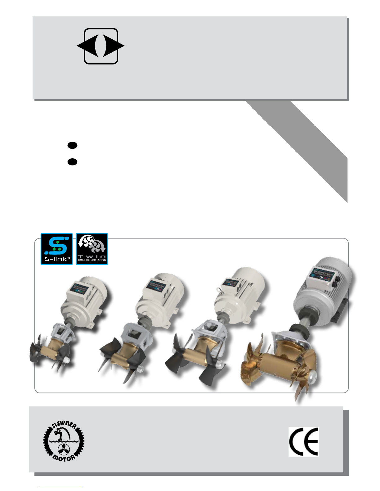
SAC240, SAC300, SAC386,
SAC513, SAC610 Series
AC Thrusters
SIDE-POWER
Thruster Systems
SAC513/SAC610 SAC_Thrusters_ABB_v1_3_April 2014
2
Innhold
NO
INSTALLATION INSTRUCTIONS
Measurements ....................................................................... 3-4
Technical specications .......................................................... 5-6
Planning & important precautions.............................................. 7
Tunnel installation
Positioning of the tunnel / thruster ............................................ 8
How to shape the tunnel ends ................................................... 9
How to prevent drag from tunnel installation ........................... 10
Possible tunnel installation in sailboats ................................... 11
Series production installation................................................... 12
Tunnel installation in a GRP boat ............................................ 13
Thruster installation
Positioning the thruster motor.................................................. 15
Gearhouse and motorbracket ............................................ 16-18
Propeller ............................................................................. 19-21
AC motor ........................................................................... 22-23
Oil tank .................................................................................... 24
Electrical installation
Schematic overview..................................................................25
Wiring diagram .........................................................................26
PDC 101 Proportional Drive Controller.....................................27
Varriable Frequency Drive ........................................................27
Power cable dimensions...........................................................28
Maintenance & service ...........................................................29
Checklist for control of the installation ..................................... 30
Important user precautions ...................................................31
Warranty statement .............................................................. 31
Service centres ..................................................................... 32
Contents
EN
DECLARATION OF CONFORMITY
We, Sleipner Motor AS
P.O. Box 519
N-1612 Fredrikstad, Norway
declare that this product with accompanying
standard remote control systems complies with
the essential health and safety requirements
according to the Directive 89/336/EEC of 23
May 1989 amended by 92/31/EEC and
93/68/EEC.
2
INSTALLASJONSVEILEDNING
Mål ........................................................................................ 3-4
Tekniske spesikasjoner ........................................................ 5-6
Planlegging og viktige hensyn ....................................................7
Tunnelinstallasjon
Plassering av tunnel/truster ...................................................... 8
Hvordan forme tunnelendene .................................................... 9
Hvordan forhindre motstand fra tunnelinstallasjon .................. 10
Alternativer for installasjon i seilbåt ......................................... 11
Installasjon ved serieproduksjon ............................................. 12
Tunnellinstallasjon i en glassberbåt ....................................... 13
Trusterinstallasjon
Plassering av thrustermotor..................................................... 15
Girhus og brakett ............................................................... 16-18
Propeller ............................................................................ 19-21
AC motor og kobling .......................................................... 22-23
Oljetank ................................................................................... 24
Elektrisk installasjon
Skjematikk ................................................................................25
Koblingsskjema ........................................................................26
PDC 101 Proportional Drive Controller.....................................27
Varriable Frequency Drive ........................................................27
Dimensjoner, hovedkabel .........................................................28
Service og vedlikehold...........................................................29
Sjekkliste for kontroll av installasjonen .................................... 30
Viktige forhåndsregler ...........................................................31
Servicesentere ...................................................................... 32
SAMSVARSERKLÆRING
Vi , Sleipner Motor AS
Postboks 519
N -1612 Fredrikstad,Norge
erklærer at dette produktet med tilhørende
standard kontrollsystemer er i samsvar med
helse, og sikkerhetskravene i henhold til Direktiv 89/336/EEC fra 23 Mai 1989, korrigert av
92/31/EEC og 93/68/EEC.
SAC513/SAC610 SAC_Thrusters_ABB_v1_3_April 2014
3
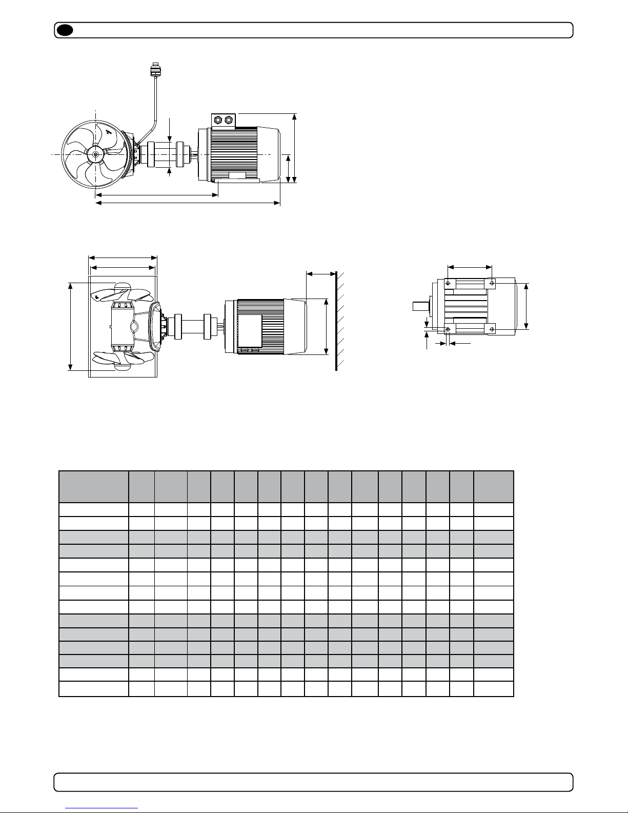
Measurements, thruster
EN
MODEL A*
(mm)
A**
(mm)B(mm)C(mm)D(mm)E(mm)F(mm)G (mm)H(mm)J*(mm)K(mm)L(mm)M(mm)N(mm)
Weight***
(kg)
SAC250-240/240-2 877 1054 250 264 356 100 314 160 380 547 19 15 254 210 92
SAC250-240/240-4 877 1054 250 264 356 100 314 160 380 547 19 15 254 210 92
SAC300-300/300-2 968 1103 300 320 356 120 314 160 380 598 19 15 254 254 108
SAC300-300/300-4 968 1103 300 320 356 120 314 160 380 598 19 15 254 254 108
SAC386-450/450-2 1174 1311 386 406 503 122 364 180 442 736 19 15 279 279 258
SAC386-450/450-4 1174 1311 386 406 503 122 364 180 442 736 19 15 279 279 258
SAC386-450/520-2 1174 1311 386 406 503 122 364 180 442 736 19 15 279 279 258
SAC386-450/520-4 1174 1311 386 406 503 122 364 180 442 736 19 15 279 279 258
SAC513-600/750-4 1326 1460 513 545 685 170 402 200 500 850 25 19 318 305 392
SAC513-750/900-4 1396 1530 513 545 685 170 445 225 550 896 25 19 356 311 462
SAC513-900/1100-4 1468 1602 513 545 685 200 445 225 550 907 25 19 356 311 495
SAC513-1100/1100-4 1505 1638 513 545 685 200 495 250 642 926 30 24 406 349 615
SAC610-1000/1300-4 1635 1797 610 646 685 200 555 280 712 1005 30 24 457 419 770
SAC610-1200/1400-4 1635 1797 610 646 685 200 555 280 712 1005 30 24 457 419 815
* With standard length universal joint shaft
THRUSTER
** With external cooling unit (optional)
*** Weight stated is for complete thruster excluding VFD
1
2
3
4
5
6
7
8
9
10
SAC 513-600/750-4
11.11.2011
1
Designed by
Date
1 / 1
Edition Sh eet
R. Hansen
Material Type Drawing nr
Copyright All rights reserved
Part nr Size Scale
Title
AC Thruster Ø513 750kg
Tolerance
NS-ISO 2768-1
SLEIPNER MOTOR AS
A1
410.000
kg
Weight
3
9
6
Ø
K
L
N
M
AC MOTOR FOOTPRINT
A
J
G
H
E
1
2
3
4
1
2
1
2
3
4
5
4
5
6
A A
B B
C C
D D
4
5
6
C C
D D
F
B
D
C
Min.
150mm
1
2
3
SAC513/SAC610 SAC_Thrusters_ABB_v1_3_April 2014
4
THIS IS A PRO-E DRAWING DO NOT MANUA LLY CHANGE - REVISE PRO-E FILE ONLY
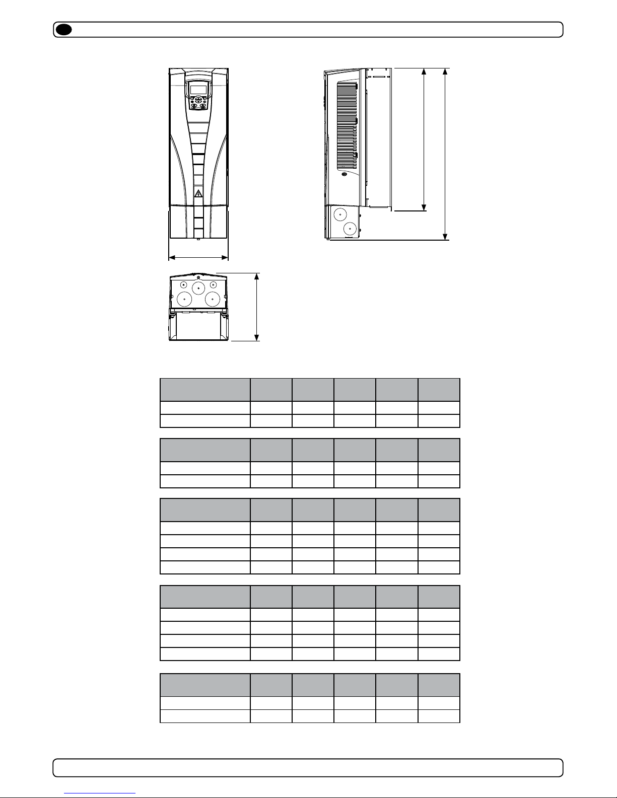
W
D
H1
H2
Measurements, VFD
EN
MODEL H1 (mm) H2 (mm) D (mm) W (mm) Weight (Kg)
SAC250-240/240-2 586 490 203 231 16
SAC250-240/240-4 586 490 203 231 16
VFD Degree of protection: IP21
MODEL H1 (mm) H2 (mm) D (mm) W (mm) Weight (Kg)
SAC300-300/300-2 689 596 203 362 24
SAC300-300/300-4 586 490 203 231 16
MODEL H1 (mm) H2 (mm) D (mm) W (mm) Weight (Kg)
SAC386-450/450-2 689 596 203 362 24
SAC386-450/520-2 888 700 302 400 69
SAC386-450/450-4 689 596 203 362 24
SAC386-450/520-4 689 596 203 362 24
MODEL H1 (mm) H2 (mm) D (mm) W (mm) Weight (Kg)
SAC513-600/750-4 689 596 203 362 24
SAC513-750/900-4 736 602 265 286 34
SAC513-900/1100-4 888 700 302 400 69
SAC513-1100/1100-4 888 700 302 400 69
MODEL H1 (mm) H2 (mm) D (mm) W (mm) Weight (Kg)
SAC610-1000/1300-4 888 700 302 400 69
SAC610-1200/1400-4 888 700 302 400 69

SAC513/SAC610 SAC_Thrusters_ABB_v1_3_April 2014
5
Technical specications
EN
Tekniske data
NO
Motor: AC Electric type (specications next page)
Gear house: Seawater resistant bronze
Gears: Hardened precision gears
Lubrication: 250mm;
Prelled, lifetime lubricated
300/386/513/610mm:
Oil bath from tank (gear oil GL-5) SAE 80W-90
Bearings: Angular contact ball bearing at propellershaft
and combination of ball bearing and needle
bearing at driveshaft.
Material: Seawater resistant bronze, protected with
anodes
Motor bracket: Seawater resistant aluminium
Tunnel: Cross spun with rowing G.R.P tunnel
Steel & aluminum tunnels available at request.
Propellers: 250mm: Composite 5-blade skew "Q-PROP"
300mm: Composite 4-blade kaplan propeller
386mm: Composite 4-blade kaplan propeller
513mm: Bronze 5-blade skew "Q-PROP"
610mm: Bronze 5-blade skew "Q-PROP"
Control system: S-LINK. cables and control panel not included.
Safety: Flexible coupling between AC motor and
driveshaft protects gearsystem against peak
loads.
Motor: AC elektrisk type (spesikasjoner neste side).
Girhus: Sjøvannsbestandig bronsje.
Tannhjul: Herdede presisjonstannhjul
Smøring: 250mm;
Forhåndsfyllt, livstidssmøring
300/386/513/610mm:
Oljebad fra tank girolje GL-5 SAE 80W-90
Lager: Vinklede kulelager på propellaksel og kombinas-
jon av kulelager og nålelager på drivaksel
Material: Sjøvannsbestandig bronse, med anodebeskyt-
telse
Motorbrakett: Sjøvannsbestandig aluminium.
Tunnel: Kryssvevet glassber.
Aluminium og ståltunnel på forespørsel.
Propell: 250mm: 5-blad skew "Q-PROP", kompositt
300mm: 4-blad kaplan propell, kompositt
386mm: 4-blad kaplan propell, komposit
513mm: 5-blad skew "Q-PROP", bronse
610mm: 5-blad skew "Q-PROP", bronse"
Kontrollsystem: S-LINK. Betjeningspanel og kabler er ikke
inkludert.
Sikkerhet: Fleksibel kobling mellom AC motor og girhus
beskytter drivsystemet mot overbelastning

SAC513/SAC610 SAC_Thrusters_ABB_v1_3_April 2014
6
Specications & performance data
Model SAC250-
240/240-X
1)
SAC300300/300-X
1)
SAC386450/450-X
1)
SAC386450/520-X
1)
Typical boat size (m•ft):
17 - 25 • 55 - 84 22 - 30 • 75 - 100 23 - 37 • 75 - 120 22 - 30 • 75 - 100
Tunnel inside diameter:
250mm/9.8" 300mm/11.8" 386mm/15.2“ 386mm/15.2“
Propulsion system:
Counter rotating Counter rotating Counter rotating Counter rotating
Thrust, continous:
240kg/529lbs 300kg/661lbs 450 kg/992 lbs 450 kg/992 lbs.
Thrust, int.:
- - - 520 kg/1146 lbs.
Motor output continous:
14 kW/19 Hp * 16,2kW/22Hp * 28 kW/38 Hp 28 kW/38 Hp
Motor output int.:
- - - 35kW/48Hp
Voltage
220/240 - 380/400 220/240 - 380/400 220/240 - 380/400 220/240 - 380/400
Max. current, continous
220/230V:
380/400V:
47,5A / 45A
27,5 A / 26A
63,5A / 61A
37A / 35A
100A / 96A
58A / 55A
100A / 96A
58A / 55A
Max. current, intermittent
220/230V:
380/400V:
- - 125A / 120A
73A / 69A
Generator load max
18,5 KVA 22 KVA 37 KVA 47 KVA
1)
-2 for 220/240V version , -4 for 380/400V version
2)
AC motor output
Model SAC513-
600/750-X
1)
SAC513750/900-X
1)
SAC513900/1100-X
1)
SAC5131100/1100-X
1)
SAC6101100/1300-X
1)
SAC6101200/1400-X
1)
Typical boat size (m•ft):
27-43
• 90-140 30-46 • 100-150 32-48 • 105-155 34-49 • 110-160 37-49 • 120-160 40-52 • 130-170
Tunnel inside diameter:
513mm/20" 513mm/20" 513mm/20" 513mm/20" 610mm/24" 610mm/24"
Propulsion system:
Counter rotating Counter rotating Counter rotating Counter rotating Counter rotating Counter rotating
Thrust, continous:
600 kg/1323 lbs. 750 kg/1653 lbs. 900 kg/1984 lbs. 1100 kg/2425 lbs. 1000 kg/2405 lbs 1200 kg/2646 lbs.
Thrust, intermittent:
750 kg/1653 lbs. 900 kg/1984 lbs. 1100 kg/2425 lbs. 1100 kg/2425 lbs. 1300 kg/2866 lbs. 1400 kg/3086 lbs.
Motor output cont.:
27 kW/38Hp 37 kW/53 Hp 49 kW/67 Hp 68 kW/93 Hp 54 kW/74 Hp 61 kW/83 Hp
Motor output int.:
37 kW/53 Hp 49 kW/67 Hp 68 kW/93 Hp - 69 kW/94 Hp 80 kW/109 Hp
Voltage
380/400 380/400 380/400 380/400 380/400 380/400
Max. current, continous
380/400V:
72A / 68A 88A/84A 103A / 98A 133A / 126A 111A / 105A 124A / 118A
Max. current, intermittent
380/400V:
88A/84A 103A / 98A 133A / 126A
- 139A / 132A 161A / 153A
Generator load MAX
50 KVA 64 KVA 86 KVA 86 KVA 90 KVA 105 KVA
Technical specications
EN
Tekniske data
NO

SAC513/SAC610 SAC_Thrusters_ABB_v1_3_April 2014
7
The recommendations made in this manual are to be used as starting guidelines only, and Sleipner Motor AS
(Side-Power) strongly recommend that prior to installation, advise should be obtained from a naval architect familiar with the particular vessel brand and potential regulations/classifications regarding the vessel.
When installed in boats approved or classified according to international or special national regulations, the installer is responsible for following the demands in accordance with these regulations/classification rules (electrical/
mechanical). The instructions in this guide can not be guaranteed to comply with all different electric/mechanic
regulations/classification rules.
Prior to installation, it is important that the installer reads this guide to ensure necessary acquaintance with this product.
This manual is intended to support educated / experienced staff and is therefore not sufcient in all details for the correct installation.
If the height/length in the room you are installing the Side-Power is limited, the Side-Power can be installed at different angles
The motor must be handled carefully.
Beware to keep installation within adviced measurements. No part of the propeller or gearhouse must be outside the tunnel.
The motor, its components (VFD, electric junction boxes etc.) or other joints and control cables must be mounted so that they will keep
dry at all times.
We advice to paint the gearhouse and propellers with antifouling. NB! Do not paint the anodes, sealings or propellershafts.
Do not nish the inside of the tunnel with a layer of gelcoat / topcoat or similiar. It is only room for a thin layer of primer and two layers
of anti-fouling between the tunnel and the propellers.
NB ! Faulty installation of the tunnel, thruster or panel will render all warranty given by Sleipner Motor AS void.
Planning and important precautions
EN
Anbefalingene i denne manualen er å anse som grunnleggende retningslinjer, og Sleipner Motor AS (Side-Power)
anbefaler sterkt at råd fra en marinearkitekt med erfaring fra den aktuelle båt typen og eventuelle klassekrav
innhentes før installasjonen påbegynnes. Ved installasjon i klassede fartøy eller i fartøy som skal oppfylle spesielle
nasjonele krav/regler (mekaniske og/eller elektriske) er installatøren ansvarlig for at disse følges. Instruksjonene i
denne manualen kan ikke garanteres å oppfylle alle krav og hensyn til slike regler.
Før installasjon er det viktig at den/de som utfører jobben leser manualen for å gjøre seg kjent med produktet
Denne manualen er laget med henblikk på kvalisert personell, og inneholder derfor ikke alle nødvendige detaljer for en komplett
installasjon
Hvis høyden/lengden i rommet er begrenset, kan thrusteren monteres i forskjellige vinkler
Motoren må behandles forsiktig
Pass på å utføre installasjonen innenfor de anviste mål. Ingen del av propell eller girhus må stikke utenfor tunellen.
Motoren med dens tilhørende komponenter ( VFD, koblingsskap etc) og kontroll kabler må monteres slik at de er tørre til enhver tid.
Vi anbefaler at girhus og propeller behandles med bunnstoff. NB! Mal ikke anoder, pakninger eller propellaksler.
Bruk ikke gelcoat / topcoat eller lignende på innsiden av tunellen. Det er kun plass for et tynt lag primer og to lag bunnstoff mellom
tunellen og propellene.
NB ! Feilaktig installasjon av tunell, thruster eller panel vill oppheve enhver garanti gitt av Sleipner Motor AS.
Planlegging og viktige hensyn
NO
DO NOT connect any other control equipment to the S-link controlled products except Side-Power original S-link products
or via a Side-Power supplied interface product made for interfacing with other controls. Any attempt to directly control or at
all connect into the S-link control system without the designated and approved interface, will render all warranties and responsibilities for the complete line of Side-Power products connected void and null. If you are interfacing by agreement with
Sleipner and through a designated Side-Power supplied interface, you are still required to also install at least one original
Side-Power control panel to enable efcient troubleshooting if necessary.
Koble IKKE til annet kontrollutstyr til S-link utstyrte produkter enn Side-Powers originale S-link produkter eller via et Side-
Power interface levert av Side-Power laget spesikt for dette formål. Ethvert forsøk på direkte kontroll eller på noen måte å
koble seg til S-link systemet uten det spesikke interface, vil gøre enhver garanti og ansvar fra Sleipner Motor AS ugyldig.
Hvis det benyttes et interface etter godgjenning fra Sleipner Motor AS er det fremdeles påkrevet med minst ett originalt
Side-Power kontrollpanel for å muliggjøre effektiv feilsøking hvis påkrevet.
SAC513/SAC610 SAC_Thrusters_ABB_v1_3_April 2014
8
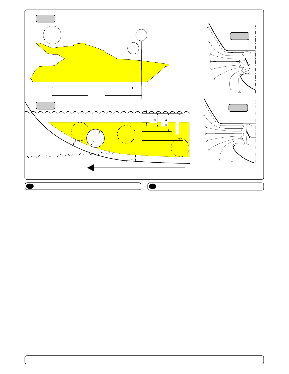
The Thruster should be as far forward as possible (Fig. 1)
Because of the leverage effect around the boats pivot point, it is
very important for the thrusters actual effect in the boat to get it as
far forward as possible. The relative distance change from the boats
pivot point to the thruster will be the change of actual thrust for the
boat.
Example :
A: 100kg thrust x 11m leverage = 1100kgm torque to rot. the boat
B: 100kg thrust x 10m leverage = 1000kgm torque to rot. the boat
In position A you will get 10% more thrust to turn the boat around.
The thruster should be placed as deep as possible (Fig. 2)
The tunnel should be placed as deep as possible for two reasons:
1. Thrust will be reduced dramatically due.
2. To get as high as possible a water pressure to get maximum
efciency from the propeller.
Generally the top of the tunnel should be a minimum of 1/2 x the
tunnel diameter below the waterline. This is an absolute minimum
and we recommend that it is at least 3/4 x tunnel diameter ()
below the waterine. A really good distance is about 1/1 x tunnel
diameter () below the waterline.
When you get the top of the tunnel 30-35 cm* / 1 feet below the
surface, other factors should be considered more important, i.e.
moving the thruster further forward.
Optimal tunnel length
If the tunnel gets to long, the friction inside will reduce the water
speed and thereby the thrust.
If the tunnel gets to short (normally only in the bottom section of
the tunnel) you can get cavitation problems as the water will not
have had time to “straigthen” itself before reaching the propel-
ler (Fig. 3/4). This cavitation will reduce performance as well as
creating a lot of noise.
The optimal tunnel length is 2 to 4 x tunnel diameter and you
should avoid tunnels longer than 6 to 7 times the tunnel diameter
as the performance reduction is then clearly noticeable.
Positioning of the tunnel / thruster
EN
Plassering av tunnel og thruster
NO
Tunnelen bør plasseres lengst mulig frem i baugen (Fig. 1)
For å oppnå mest mulig moment rundt båtens dreiepunkt, er det
meget viktig å plassere tunnelen så langt fremme som mulig.
Avstanden fra båtens dreiepunkt til thruster vil ha stor betydning
på thrusterens effekt.
Eks.:
A: 55kg skyvekraft x 11m moment = 605kgm skyvekraft
B: 55kg skyvekraft x 10m moment = 550kgm skyvekraft
Posisjon A vil gi 10% mer skyvekraft til rotasjon.
Tunnelen skal plasseres dypest mulig (Fig. 2)
Tunnelen skal plasseres så dypt som mulig av to grunner:
1. Så luft ikke suges ned i tunnelen og ødelegger skyvekraften.
2. Ved å øke vanntrykket jobber propellen mer effektivt.
Hovedregelen er at tunnelen skal plasseres minimum ½ x tunnelen dia. under vannlinje. Anbefalt dybde er minst ¾ x dia. under
vannlinje (). Når tunnelen er plassert 33-35 cm under vannlinjen
bør andre faktorer vurderes som viktigere, d.v.s. å plassere tunnelen lengre frem.
Optimal tunnel lengde
Dersom tunellen blir for lang vil friksjonen i tunellen reduser vannhastigheten og derved effekten.
Dersom tunellen blir for kort (normalt bare i nedre del av tunel-
len) kan det oppstå kavitasjons problemer da vannet ikke har tid
/ av-stand til å «rette opp strømningsretningen» før det treffer
propellen (Fig. 3&4). Denne kavitasjonen vil redusere effekten og
lage mye støy.
Den optimale tunell lengden er 2 til 4 ganger tunell diameteren
og dersom tunellen blir så mye som 6 til 7 ganger diameteren i
lengde vil effekt tapet bli klart merkbart.
A = 11,0m
B = 10,0m
A
B
Pivot
point
m
i
n
.
1
/
3
Ø
Ø
m
i
n
.
1
/
3
Ø
3/4Ø
☺
1/1 Ø
☺
☺
30 - 35 cm*
min.
1/2Ø
Fig. 1
Fig. 2
Fig. 3
Fig. 4
SAC513/SAC610 SAC_Thrusters_ABB_v1_3_April 2014
9
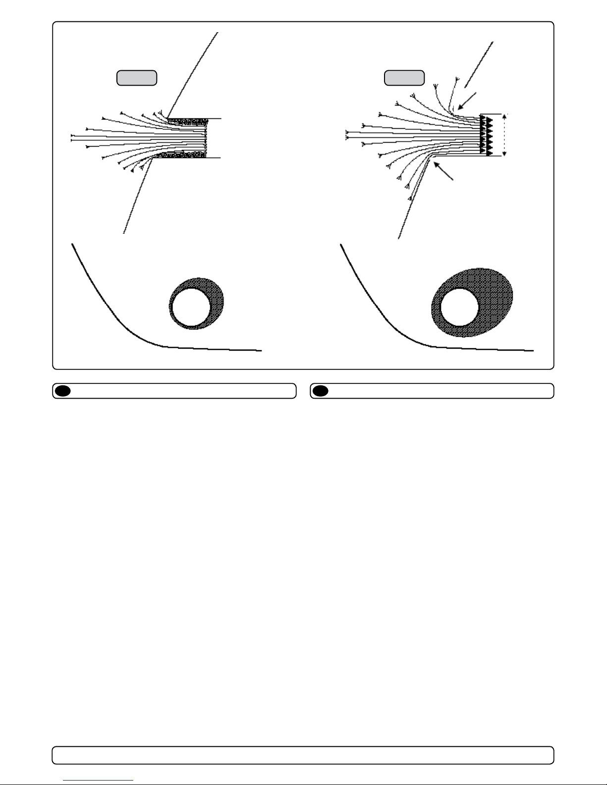
Rounded tunnel ends will maximize thrust and minimize noise.
We recommend to round the tunnel connection to the hull-side as
much as possible.
The optimum rounding has a radius of 10% of the tunnels diameter.
Important advantages over sharp tunnel to hull connections are:
1. The rounded tunnel end will prevent creation of turbulence /
cavitation that will come from a sharp tunnel end when water
passes by fast, thereby preventing a double negative impact on
the thrust and noise level (Fig. 1&2).
- The turbulence / cavitation blocks the outer area of the tunnel
and thereby reduces the effective tunnel diameter and thrust.
- The turbulence / cavitation hits the propeller and thereby
reduce the propellers performance and creates noise.
2. The curved tunnel end makes the thruster take water also from
along the hull-side, creating a vacuum that will suck the boat
sideways and thereby give additional thrust (Fig. 3&4).
With a sharp tunnel end, the thruster will be unable to take
water from along the hull-side, and you will not get the desired
vacuum and additional thrust.
This "free" additional thrust can in optimal installations be as
much as 30 - 40% of the total thrust.
NB! A Sidepower thruster propeller does not cavitate at working
speed so that all cavitation and cavitation noise in the tunnel will be caused by the tunnel installation.
NB! Even if it is not possible to make the perfect rounding, it is
very important to round the tunnel end as much as possible.
A angled tunnel to hull connection will also do much of the
same job as a rounded connection (see page 20, Fig. 1b&1d).
Tunnel ends
EN
Fig. 2
Fig. 4
Fig. 1
Fig. 3
R = 0,1 x D (10%)
R = 0,1 x D (10%)
D
Tunnelåpninger
NO
Avrundede åpninger vil minke støy, og maksimere effekt.
Vi anbefaler å avrunde tunnelåpningene mest mulig.
Den optimale avrundingen har en radie som er 10% av tunnelens
diameter.
Hvorfor er en avrundet tunnelåpning så viktig?
1. En avrundet tunnelåpning vil forhindre at det oppstår turbulens / kavitasjon, noe som vil oppstå ved en installasjon med
skarpe kanter. Turbulensen forårsaker mer støy, og begrenser
skyvekraften.
- Turbulensen / kavitasjonen blokkerer tunnelen og svekker
skyvekraften.
- I det kavitasjon og turbulens når propellen påvirkes ytelsen til
denne og øker støyen.
2. En avrundet tunnelåpning gjør også at thrusteren suger vann
langs skroget på båten. Dermed oppstår det et lavtrykk som
vil hjelpe å suge båten i dreieretningen. Med skarpe åpninger
klarer ikke thrusteren å suge vann langs skroget, og lavtrykket
uteblir. Så mye som 40% av skyvekraften har blitt målt til å
ligge her på noen installasjoner.
NB! Propellene til Side-Power thrustere kaviterer ikke på arbeid-
shastighet, så kavitasjon og støy som oppstår som følge av
kavitasjon, skapes av tunnelinstallasjonen.
NB! Selv der en perfekt avrunding ikke er mulig er det viktig å
runde av kantene så mye som mulig, en tunnelåpning med
skråkant vil ha stor effekt fremfor en med skarpkant (se side
20, ill. 1b & 1d).
SAC513/SAC610 SAC_Thrusters_ABB_v1_3_April 2014
10
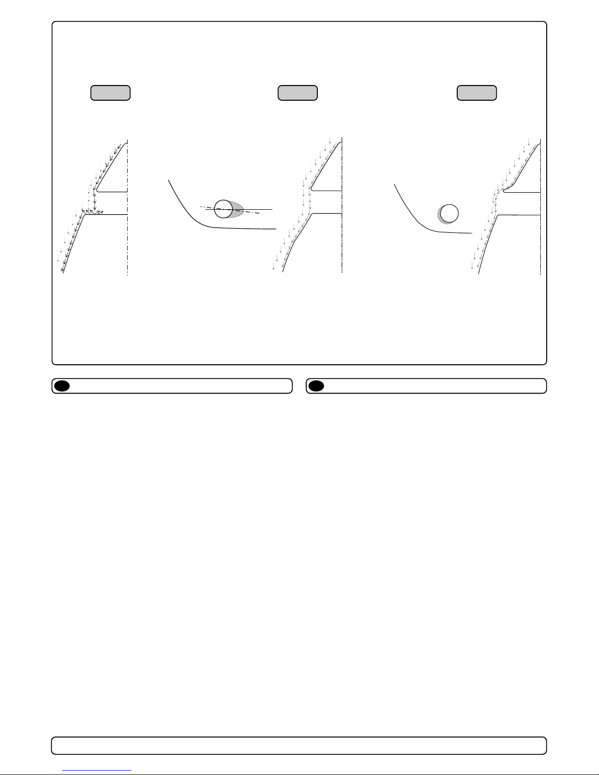
A possible problem in sailboats or fast powerboats, is that they
get a drag from the back face of the tunnel, as this becomes a
“at” area facing the water ow (Fig. 1).
This can also create problems with the thruster spinning (passive)
and making noise while sailing or driving the boat with water being pushed through the tunnel at high speed.
This can be solved in two different ways, depending on what is
possible or more easy to do.
1. The best solution which normally reduces the drag most, is to
make a recess in the hull at the back of the tunnel.
Thereby the back face is gone and about all the drag (Fig. 2).
The depth and shape of this recess will depend on the boat.
Basically you should not see the back face of the tunnel when
standing directly in front of the tunnel at the angle of the boats
centreline.
The angle up or down backwards of the insert in the hull, de-
pends on the hullshape, but normally it is angled slightly down
because of the waterow on this area of the hull.
2. The drag will also be reduced a lot, especially in fast power
boats, by making a deector / spoiler in front of the tunnel.
This will push the waterow out from the hull so that most of it
passes by the back face of the tunnel (Fig. 3).
The shape and size of this deector will depend on the hull
shape. Basically you should not see the back face of the tunnel
when standing directly in front of the tunnel at the angle of the
boats centreline.
The easiest way of making this is to let a part of the tunnel
stick out in the lower forward area of the hole, and use this as
a support to mould a soft curve / spoiler shape.
Remember to still round the tunnel ends as much as possible to
get optimum thruster performance and minimum noise.
More information on how to practially do this on pages 6.
Prevent drag from tunnel
EN
Motstand forårsaket av tunnel
NO
Et mulig problem for seilbåter eller meget hurtiggående båter er
motstand i tunnelen. Aktre ende på tunnelen vil være en liten lod-
drett ate mot vannstrømmen som skaper uønsket motstand.
Denne aten kan også forårsake problemer med at vann føres
inn i tunnelen under seilas, eller kjøring i høy fart og får da propellen til å rotere, dette skaper uønsket støy.
Det er to mulige løsninger på problemet, avhengig av hva som er
enklest å få til på båten.
1. Den løsningen som vanligvis reduserer motstanden mest er å
lage en fordypning i skroget i aktre ende av tunnelåpningen.
Den loddrette aten vil da forsvinne og dermed motstanden.
Hovedregelen å følge er at bakkanten av tunnelen ikke skal
synes når man står rett foran båten og titter akterover langs
båten senterlinje. Dybden, utformingen og vinkling av fordypningen avhenger av båttypen, og hvordan vannet følger skro-
get, men de este båter vil være tjent med en fordypning som
vinkler lett nedover (Fig. 2).
2. Motstanden vil også reduseres av en spoiler i forkant av
tunnelen. Spoileren fører det meste av vannstrømmen rundt
og forbi tunnelen. Størrelsen og utformingen på spoileren
avhenger av båten. Hovedregelen er at bakkanten av tunnelen
ikke skal synes når man står rett foran båten og titter akterover
langs båten senterlinje. Den enkleste måten å lage spoileren
på er å la tunnelen stikke ut i forkant av tunnelen, og forme
spoileren opp mot den (Fig. 3).
Det er alltid viktig å avrunde tunnelåpningene mest mulig for å
motvirke støy og for å få mest mulig effekt av thrusteren.
Mer informasjon om dette på side 10.
☺☺
☺☺
☺
��
��
�
Fig. 2Fig. 1 Fig. 3
☺☺
☺☺
☺

SAC513/SAC610 SAC_Thrusters_ABB_v1_3_April 2014
11
Some boats is very at bottomed and has a very shallow draft in
the bow section. It might be very difcult not to say impossible to
t a tunnel thruster the usual way, at least as far forward in the
hull as a thruster should be (Fig. 1).
However, it is possible to install a tunnel thruster even when the
hull does not directly support the tting of a tunnel.
This is done by tting the tunnel halfway into and halfway under-
neath the exisiting hull and then strengthen it and smoothening
the waterow by moulding a bulb around / underneath the tunnel.
This will allow installation in good position on the boat, maintaining
the reliability and space advantages of a tunnel thruster.
This can also be a good installation method for at bottomed
barges to avoid extremely long tunnels and huge oval tunnel
openings in the hull.
If the tunnel is over 250 cm long at its deepest point, it is recom-
mend that is is supported by a bulkhead as suggested in g. 2
and 3.
Tunnel installation in at bottomed hulls
EN
Tunnelinstallasjon i atbunnede skrog
NO
Noen båter har brede skrog som ikke stikker dypt i baugen.
Skrogtypen gjør det vanskelig å installere en thrustertunnel på
vanlig måte, spesielt med tanke på å plassere den langt nok frem
(Fig. 1).
Thrustertunneler kan allikevel installeres i de este båter. Dette
gjøres ved å la en del av tunnelen stikke ut i underkant av skroget. Tunnelen er sterk nok til dette, og thrusteren blir plassert lav
nok og langt nok fremme.
Dette gjøres ved at øvre halvdel av tunnelen støpes inn i skroget,
tunnelen styrkes i underkant ved å støpe en kul rundt tunnelen og
jevne den ut mest mulig.
Denne installasjonen kan også være gunstig for båter med ate
bunner, for å unngå ekstremt lange tunneler og store ovale tunnelåpninger.
Er tunnelen over 250 cm lang, anbefales at den støttes opp av et
skott som vist på g. 2 and 3.
Fig. 2
Fig. 3
Fig. 1
Min
��
��
�
☺☺
☺☺
☺
Pos. B
Pos. A

SAC513/SAC610 SAC_Thrusters_ABB_v1_3_April 2014
12
Boat builders having thrusters as standard, or delivering a large
portion of one or more models with thrusters, have the opportunity to make a perfect tunnel installation, while saving both time
and money on each installation (Fig. 1).
The solution is to make an insert / plug in the hull mould, which
prepares the hull for an easy tunnel installation with features for
maximum thrust and minimal drag (Fig. 2).
This insert / plug in the mould is not very difcult to make, and as
it will have to be a "bolt on" in the mould in order to get the boat
out, you can still make boats without this hull feature. (Some boat
builders have this in the hull also on boats that are delivered with-
out a thruster as they know many people will t this later)
By having a at surface to t the tunnel to, the installation time
and cost for the tunnel will also be reduced as:
- it is very easy and fast to cut the now circular hole for the tunnel
- it is easier to mould inside all around the tunnel
- you save tunnel length
The plug in the mould can also be made so that it can be a xed
part of the mould, but the rounded end option must then be made
later to get the hull out of the mould (Fig. 3&4).
Series production installation
Fig. 1
Fig. 3
Fig. 2
Fig. 4
EN
a1
b
a1
a2
a2
b
a1
a2
b
D
Radius =
D x 0,1
A
a1
b
a1
a2
a2
b
a1
a2
d
d
c1
c2
c2 c3
d
b
c3
c1
Båtbyggere som har trustere som standard eller leverer en eller
ere modeller med valgfri truster i stort antall har mulighet for å
lage en perfekt tunnelinstallasjon og samtidig spare tid å penger
(Fig. 1).
Løsningen er å lage en plugg/innsats i formen, som klarrgjør
skroget for anklest mulig tunnelinstallasjon og som samtidig har
perfekt utforming for maksimal trust og minimal motstand (Fig. 2).
Pluggen/innsatsen er ikke komplisert å lage og siden den må
skrus fast i formen på grunn av slipp kan skrogene fremdeles
lages uten denne løsningen. (Enkelte båtbyggere velger også
denne løsningen på båter levert uten truster da de vet at mange
vil velge å ettermontere en truster)
Ved å ha en rett ate å montere tunnelen på, reduseres installas-
jonstiden og kostnaden for tunnelen siden:
- det blir veldig enkelt og raskt å skjære ut det nå sirkulære hullet
til tunnelen
- det er enklere å støpe inn tunnelen langs hele omkretsen
- du sparer lengde på tunnelen
Pluggen i formen kan også lages på en slik måte at den inngår
som en fast del, men da må avrundingen lages etterpå for å
oppnå slipp i formen (Fig. 3&4).
Installasjon ved serieproduksjon
NO

SAC513/SAC610 SAC_Thrusters_ABB_v1_3_April 2014
13
We recomend that a professional does the breglass tting
of the tunnel. These instructions are only general, and do not
explain in any way the details of breglass work. Problems
caused by faulty installation of the tunnel, are the installers
full responsibility.
Find the position in the boat considering the information given
earlier in this manual and the applicable measurements for the
thruster model you are installing.
Mark the centre of the tunnel on both sides. Drill a 6mm hole
horizontally in these marks (Fig. 1) .
Bend a ø 5mm steel bar as shown with the "tip" bent back at the
tunnel radius and mark the circle for the tunnel opening (outside
diameter of the tunnel). Cut the hole with a jigsaw (Fig. 2).
Grind off the gelcoat and polyester so that you are down in the
“real breglass” in an area of 12cm around the hole both inside
and outside in the hull to cast the tunnel to the hull (Fig. 3).
Insert the tunnel and mark its shape to t the hull (Fig. 4). If you
are installing with a deector/spoiler, leave a part or the tunnel of
the front- and underside of the tunnel to have a base for this (see
page 12, Fig. 2). Cut the tunnel ends to the desired shape and
lightly sand its surface and clean with aceton or similar where you
are going to apply breglass.
NB! Do not cast/glass on the area were the thruster will be
placed.
Then cast the tunnel to the inside of the hull, use at least 8 layers
of 300 g glass and resin, preferrably alternating mat and rowing
types of breglass (see page 18, Fig. 1). If you are rounding the
tunnel ends to the perfect 10% radius you may in some cases
have to make further layers inside to preserve the desired hull
thickness.
NB ! Make sure that any gap between the tunell and the hull are
completely lled with resin/breglass. In areas where you can not
access to make normal layers of resin/breglass, a resin/ breglass mixture must be lled in that area.
R
D
Tunnel installation
Fig. 1
Fig. 3
Fig. 4
Fig. 2
EN
Tunnelinstallering
NO
Sleipner Motor anbefaler at innstøping av glassbertunnelen
utføres av kyndig personell. Denne instruksjons manua-
len gir ikke detaljerte opplysninger om glassberstøpning.
Problemer som skyldes installering er installatørens fulle
ansvar.
Bestem plassering av tunnelen ut i fra informasjonen gitt tidligere
i manualen, og de angitte mål for thrusteren du skal installere.
Merk av senter på tunnelen på babord og styrbord side. Bor et 6
mm vannrett hull, på begge sider (Fig. 1).
Bøy til og tilpass en 5 mm stålstang, som vist på g. 2 der den
tilbakebøyde enden skal markere tunnelens radius. Stikk enden
inn å marker tunnelens ytre diameter, skjær ut hullet med en
stikksag (Fig. 2).
Puss av gelcoat og polyester så glassberen ligger bar i et 12 cm
stort område rundt tunnel hullet. Dette må gjøres på innsiden og
utsiden av skroget, før tunnelen støpes fast i skroget (Fig. 3).
Sett inn tunnelen å marker hvor det skal kappes for å passe i
skroget (Fig. 4). Hvis det skal støpes en spoiler i forkant av tunnelen bør en del av tunnelen stikke ut i for og underkant av skro-
get for å støpe spoileren mot (Side 10, Fig. 2). Kapp tunnelen i
ønsket størrelse. Slip lett med slipepapir, og vask med aceton der
hvor det skal støpes med glassber.
NB ! Det må ikke støpes der hvor thrusteren skal monteres.
Støp fast tunnelen først på innsiden av skroget, bruk minst 8 lag
med 300 g Glassbermatte, og polyester. Ved bruk av alternative
materialer, glassber matter eller rovingtyper (Se s. 10, Fig. 1).
Hvis tunnelåpningene avrundes til den optimale 10% radius må
ofte legge ekstra lag med polyester glassbermatte på innersiden
av tunnelen, for å oppnå riktig tykkelse i forhold til skrogtykkelsen.
NB ! Forsikre deg om at overgangene mellom tunel og skrog er
nøye sammenstøpt. På steder en ikke kommer til med vanlige lag
med polyester/glassber matte, sørg for og lage en blanding av
polyester og glassber, som fylles i dette.

SAC513/SAC610 SAC_Thrusters_ABB_v1_3_April 2014
14
Soften the edges with a radius of 10% of the tunnel diameter
(Fig. 1a) or make a slope with a length of 10 - 15% of the tunnel
diameter (Fig. 1c). If this is not possible, atleast round the tunnel
end as much as possible.
We advice to also cast two layers on the outside of the tunnel/
hull for an area 6-8cm (Fig. 1c&1d).
You must apply gelcoat/topcoat/epoxy on the areas outside where
you have grounded or moulded to again make these waterproof.
NB ! All original Sidepower tunnels are fully waterproof
when they are delivered.
This means that unless you want, because of special reasons, to
have another colour on it, you do not have to apply Gelcoat/Topcoat or the several layers of primer that is necessary on the boats'
hull to make it waterresistant.
Sand it very lightly and apply one layer of primer to make the
antifouling sit.
The original Sidepower tube itself is fully waterresistant without
treatment exceptin the areas where you have bonded it to the
hull.
Apply gelcoat/topcoat/epoxy paint and primer on the areas where
you have grounded or moulded as these areas give the water
access to the hull which normally is not waterproof without these
applications outside.
PS!
Avoid all casting where the motor-bracket is to be
placed, as this will cause mist and possible failure
of the gearhouse.
Tunnel installation (Cont.)
EN
Fig. 1a
Fig. 1
Fig. 1b
Fig. 2
Fig. 3
Fig. 1d
Fig. 1c
Tunnelinstallering (Forts.)
NO
Rund av tunnelendene med en radius 10% av tunneldiameter
(Fig. 1a), eller lag en skråkant 10-15% av tunneldiameter (Fig.
1c). Der dette ikke er mulig skal tunnel kantene rundes av mest
mulig.
Vi anbefaler å støpe to lag utenpå tunnelavrundingen og over et
område på 6-8cm (Fig. 1c & 1d).
Gelcoat eller lignende må påføres på områdene der det har blitt
pusset eller støpt for å gjøre glassberen vanntett.
NB ! Alle originale Side-Power tunneler er vanntette ved
levering!
Så fremt man ikke ønsker en annen farge er det ikke nødvendig å
påføre Gelcoat, Topcoat og ere lag med primer for å gjøre tunnelen vanntett.
Puss tunnelen med nt slipepapir og påfør et lag primer for å få
bunnstoff til å sitte.
Side-Powertunnelen er helt vanntett uten behandling med unntak
av de områder det som er støpt fast i skroget.
Påfør Gelcoat/Topcoat/epoxy og primer på de områder som er
pusset ned eller støpt. Vann skal ikke ha direkte kontakt med
glassberen i skroget fordi dette normalt ikke er vanntett.
PS! Det må ikke støpes der braketten til thrusteren skal stå.
Passformen er nøyaktig tilpasset, og en feilplassert brakett kan forårsake svikt i girhus.

SAC513/SAC610 SAC_Thrusters_ABB_v1_3_April 2014
15
Plassering av thruster
NO
Posistioning the thruster
EN
B
C
D
D1D
2
D1 = D2
Centre line gearleg/thruster
If the tunnel is over 250 cm long at its deepest point, it is recom-
mend that is is supported by a bulkhead as suggested in g. 1
and 2.
The AC motor must be mounted on a separate bedding placed
according to g. 3 & 4. The bedding must dimensioned to support
the weight and torque specied in the technical data, page 4.
The bedding must be in the correct height so that the angle of the
cardan shaft do not exceed +/- 1.5 degrees (g. 5).
The distance from the centerline (g. 6) of the tunnel to the top of
the bedding for the specic thruster/motor combination is found
as measurement G on page 3. Ensure that the bedding is parallel
to the centerline by checking the distance in both ends of the
bedding (Fig.5)
Mounting holes in the bedding should be drilled according to
measurements J though M on page 3 for the specic thruster/motor combination.
Fig. 3
Fig. 4
Fig. 5
Fig. 6
Fig. 7
Er tunellen over 250 cm lang i underkant, anbefales at den
støttes opp av et skott som vist på g. 1 and 2.
AC-motoren må monteres på en frittstående bedding som vist på
g. 3 & 4. Beddingen må dimensjoneres slik at den tåler belastningen gitt av vekt og moment angitt i tabell på side 4.
Beddingen må plasseres lik at mellomakselen ikke får en større
vinkel enn +/- 1,5 grader.
Avstanden fra tunellens senterlinje (g. 6) til beddingens topp er
angitt for de forskjellige thruster og motorkombinasjoner på side
3 som mål G. Kontroller at toppen på beddingen er parallell med
senterlinjen ved å måle avstanden I hver ende av beddingen
(Fig.5)
Hullene for montering av AC-motoren borres i henhold til målene
angitt som J til M på side 3 for den aktuelle thruster/motorkombinasjonen.
Fig. 1
Fig. 2

SAC513/SAC610 SAC_Thrusters_ABB_v1_3_April 2014
16
Fig. 2
Bolt tightening forces:
Bolts (2x) holding gearhouse to bracket:
SE80/100: 17 Nm (12,4 lb/ft)
SE130: 33 Nm (24lb/ft)
Fig. 1a
PORT STARBOARD
S
P
Fig. 4
Fig. 3
7
28,0mm
1,1"
Ø 9mm
0,35"
TUNNELS
CENTRELINE
BOATS
CENTRELINE
Ø 32mm
1,26"
40,0mm
1,57"
Ø 11,00mm
7/16"
TUNNELS
CENTRELINE
BOATS
CENTRELINE
Ø 46,00mm
1,81"
Fig. 1b
SH100: 17 Nm (12.4 lb/ft)
SH160/SH240: 33 Nm (24 lb/ft)
SH100/185T
SH160/215T - SH240/250TC
Montering av girhus og brakett,
250mm
NO
Fitting gearhouse and motor bracket,
250mm
EN
Bolt tightening forces:
Bolts (2x) holding gearhouse to bracket:
33 Nm (24 lb/ft)
Fig. 2
7
40,0mm
1,57"
Ø 11,00mm
7/16"
TUNNELS
CENTRELINE
BOATS
CENTRELINE
Ø 46,00mm
1,81"
Fig. 1b
SH160/215T - SH240/250TC
Fig. 2
7
Fig. 1
Fig. 2
1. Mark the centreline of the tunnel and the boats centreline.
The gearleg must be tted with the P-mark facing port and S-mark
facing starboard (Fig. 4) for the thrust direction to correspond with the
control panel
2. Use the gearhouse gasket (7) to mark the centre of the holes and
double check the measurements. Place the thruster in the boats
centreline with the bolt hole as the centre (Fig. 1). It is absolutely
necessary that all holes are in-line with the tunnels’ centreline to
ensure precise installation, as the clearance between the
propellers and the tunnel is minimal to ensure best possible
performance.
3. There must be no casting where the motor bracket is to be placed,
as this will cause possible failure of the gearhouse. The motor
bracket must t steady on the tunnel, if the tunnel is not smooth,
all bumps or uneven parts must be grinded smooth.
4. Drill the centre-hole ø 46mm and then the two screw-holes ø 11mm.
5 Try the lower-unit in the tunnel (without the zinc anodes and the
lower part of the exible coupling) by using the gasket inside the
tunnel. Try on the propellers to make sure they are in the middle of
the tunnel and turn freely with the same clearing from each blade to
the tunnel. Use appropriate sealant to ensure that no leakages
occur.
6. Push the gearhouse through the main hole in the tunnel and push
the gearhouse and motor-bracket gently together.
7. Screw the lower unit and the motor-bracket together with the two
provided bolts (Fig. 3).
1. Marker båtens og tunnelens senterlinje på tunnelen.
Girhuset må plasseres med enden merket P mot babord og enden
merket S mot styrbord (Fig. 4) for at skyveretning skal korrespondere
med merkingen på kontrollpanelene.
2. Bruk girhuspakningen for å sjekke målene (7). Thrusteren skal plas-
seres på styrbord side av senterlinjen med boltehullet i midten av
båten (Fig. 1). Alle hull må være på båtens eller tunnelens senterlinje
for å får til en presis installasjon. Dette skyldes at det er meget liten
klaring mellom tunnelveggen og propellen.
3. Tunnelen må ha en jevn overate der braketen skal festes, all støp,
evt glassber eller epoxy rester må pusses ned så braketen passer
jevnt på tunnelen. Ujevnheter her vil resultere i svikt i girhuset.
4. Bor senterhullet Ø 46 mm, og de to boltehullene Ø 11 mm
5. Prøv girhuset i tunnelen sammen med pakning 1m.m. Monter propell
å sjekk at den er i midten av tunnelen. Hvis propellen ikke er i midten
av tunnelen, forsøk å bruk den endre pakningen, eller begge to samtidig. Hvis tunnelen ikke har en jevn overate så kan et tetningsmateriale brukes for å sikre mot lekkasje.
6. Før girhuset gjennom hovedhullet i tunnelen og monter braketten og
girhuset forsiktig sammen.
7. Skru sammen motorbraketten og girhuset med orginalbolter (Fig. 3).

SAC513/SAC610 SAC_Thrusters_ABB_v1_3_April 2014
17
Fig. 2
Bolt tightening forces:
Bolts (2x) holding
gearhouse to bracket:
33 Nm (24 lb/ft)
A
Fig. 3
G
E
A
R
O
I
L
E
P
9
0
3
4
1
2
Fig. 4
Montering av girhus og brakett,
300mm/386mm
NO
Fitting gearhouse and motor bracket,
300mm/386mm
EN
Fig. 1a
1. Mark the centreline of the tunnel and the boats. The propellers
and the lower unit must be completely inside the tunnel.
2. Use the gasket (A) to mark the centre of the holes and double
check the measurements.
NB ! All holes must be in-line with the tunnels' centreline for
precise installation, as the clearance between the propeller
and the tunnel is minimal.
3. There must be no casting where the motor bracket is to be
placed, as this will cause possible failure of the gearhouse.
The motor bracket must t steady on the tunnel, if the tunnel
is not smooth, all bumps or uneven parts must be grinded
smooth.
4. Drill the main hole and then the two screw holes(g 1a/g 1b
according to model).
5. Prell the gearhouse with gear oil type EP90 through the hole
for the oildrain screw (4). Make sure to get the copper gasket
(3) on again.
6. Fit the lower-unit in the tunnel with the gasket inside the
tunnel. Try on the propeller to make sure it is in the middle of
the tunnel. If the tunnel is not plain, use some Sikaex on or
other sealant on the gasket to ensure that no leakages occur.
NB ! Make sure that no sealant gets in to the oil holes (2).
7. Make sure that there is some oil or grease on the O-rings in the
motor bracket before mounting it together with the gearhouse,
as no lubrication could cause serious damage to the O-rings.
8. Push the gearhouse through the main hole in the tunnel and
push the gearhouse and motor-bracket gently together.
9. Screw the lower unit and the motor-bracket together with the
two provided bolts (g 4.).
1. Marker båtens og tunnelens senterlinje på tunnelen.
2. Bruk girhuspakningen for å sjekke målene (A). Alle hull må
være på båtens eller tunnelens senterlinje for å får til en
presis installasjon. Dette skyldes at det er meget liten klaring
mellom tunnelveggen og propellen.
3. Tunnelen må ha en jevn overate der braketen skal festes,
all støp, evt glassber eller epoxy rester må pusses ned så
braketen passer jevnt på tunnelen. Ujevnheter her vil resultere
i svikt i girhuset.
4. Bor senterhullet og bolthull iht. g 1a/g 1b avhengih av
modell
5. Forfyll girhuset med girolje av typen EP90 gjennom hullet til
oljedreneringsskruen (4). Pass på at kopperpakningen (3) er
på plass når skruen settes tilbake.
6. Prøv girhuset i tunnelen sammen med pakning 1mm. Monter
propell og sjekk at den er i midten av tunnelen. Hvis propellen
ikke er i midten av tunnelen, forsøk å bruk den andre
pakningen, eller begge to samtidig. Hvis tunnelen ikke har en
jevn overate kan Sikaeks eller lignende tetningsmateriale
brukes for å sikre mot lekkasje.
NB: Pass på at ikke oljekanalene (2) blir tettet av
tetninngsmassen.
7. Sørg for at det er litt olje eller grease på o-ringene i
motorbraketten før girhuset monteres slik at de ikke skades
8. Før girhuset gjennom hovedhullet i tunnelen og monter
braketten og girhuset forsiktig sammen.
9. Skru sammen motorbraketten og girhuset med orginalbolter
(Fig. 4).
SH420/SH550
70,0mm
2 3/4"
Ø 17mm
2/3"
TUNNELS
CENTRELINE
BOATS
CENTRELINE
Ø 83mm
3 1/4"
Fig. 3
Fig. 1
A
B
3
4
2
Fig. 3
48,0mm
1,89"
Ø 11,00mm
7/16"
TUNNELS
CENTRELINE
BOATS
CENTRELINE
Ø 50,50mm
2"
40,0mm
1,57"
Ø 11,00mm
7/16"
TUNNELS
CENTRELINE
BOATS
CENTRELINE
Ø 46,00mm
1,81"
Fig. 1
SP 220 HYD
SP 220 HYD / SP 300 HYD
Fig. 2
SP 300 HYD
Fig. 2
Bolt tightening forces:
Bolts (2x) holding
gearhouse to bracket:
33 Nm (24 lb/ft)
A
Fig. 3
G
E
A
R
O
I
L
E
P
9
0
3
4
1
2
Fig. 4
SP 300 HYD
Fig. 1
Fig. 1b
Bolt tightening forces:
Bolts (2x) holding
gearhouse to bracket:
300mm: 33 Nm (24 lb/ft)
386mm: 150 Nm (109 lb/ft)
300mm
386mm

SAC513/SAC610 SAC_Thrusters_ABB_v1_3_April 2014
18
1 Marker båtens og tunnelens senterlinje på tunnelen.
Girhuset må plasseres med enden merket P mot babord
og enden merket S mot styrbord for at skyveretning skal
korrespondere med merkingen på kontrollpanelene.
2. Bruk girhuspakningen for å sjekke målene (7). Trusteren skal
plasseres på styrbord side av senterlinjen med boltehullet i
midten av båten (Fig. 1). Alle hull må være på båtens eller
tunnelens senterlinje for å får til en presis installasjon. Dette
skyldes at det er meget liten klaring mellom tunnelveggen og
propellen.
3. Tunnelen må ha en jevn overate der braketen skal festes,
all støp, evt glassber- eller epoxy-rester må pusses ned
så braketten passer jevnt på tunnelen. Ujevnheter her vil
resultere i svikt i girhuset.
4. Bor senterhullet og de re boltehullene i henhold til Fig 1.
5. Fyll girhuset med 4,5 liter GL-5 girolje.
6. Prøv girhuset i tunnelen sammen med pakning. Monter
propeller og sjekk at de er i midten av tunnelen. Hvis
propellene ikke er i midten av tunnelen, forsøk å bruk
den andre pakningen, eller begge to samtidig. Bruk
tetningsmateriale for å sikre mot lekkasje.
7. Før girhuset gjennom hovedhullet i tunnelen og monter
braketten og girhuset forsiktig sammen.
8. Skru sammen motorbraketten og girhuset med orginalbolter
og låseskiver (Fig. 2). Tiltrekningsmoment: 60Nm
9. Lås boltene i henhold til Fig. 3
1. Mark the centreline of the tunnel and the boats centreline.
The gearhouse must be tted with the gearhouse lid (the
screwed in lid behind one of the propellers) on the starbord
side of the boat for the thrust direction to correspond with the
controlpanel.
2. Use the gearhouse gasket (7) to mark the centre of the holes
and double check the measurements.
Place the thruster in the boats centreline with the bolt hole
as the centre (Fig. 1). It is absolutely necessary that all holes
are in-line with the tunnels' centreline to ensure precise
installation, as the clearance between the propellers and the
tunnel is minimal to ensure best possible performance.
3. There must be no casting where the motor bracket is to be
placed, as this will cause possible failure of the gearhouse.
The motor bracket must t steady on the tunnel, if the tunnel
is not smooth, all bumps or uneven parts must be grinded
smooth.
4. Drill the centre-hole and then the four screw-holes according
to g. 1.
5. Fill the gearhouse with 4,5 liters of GL-5 gear oil
6. Try the lower-unit in the tunnel by using the gasket inside
the tunnel. Try on the propellers to make sure they are in the
middle of the tunnel and turn freely with the same clearing
from each blade to the tunnel. Use some sealant to ensure
that no leakages occur.
7. Push the gearhouse through the main hole in the tunnel and
push the gearhouse and motor-bracket gently together.
8. Screw the lower unit and the motor-bracket together with the
four provided bolts and lock washers (Fig. 2). Tighten with 60
Nm.
9. Lock the bolts according to g. 3
Montering av girhus og brakett,
513mm/610mm
NO
Fitting gearhouse and motor bracket,
513mm/610mm
EN
3
4
5
6
B B
C C
D D
95mm
3,74"
25mm
0,98"
1
2
0
m
m
4
,
7
2
"
16mm
0,
6
3"
A
1
2
3
4
5
6
7
8
9
1
2
3
4
5
6
1
2
3
5
4
6
6
7
8
9
10
11
12
13
14
15
1
Fig. 1
Fig. 2
Fig. 3
Tighten to 60Nm

SAC513/SAC610 SAC_Thrusters_ABB_v1_3_April 2014
19
5
3
2
1
4
Locktite
NO
Fitting propellers, 250mm
EN
Montering av propeller, 250mm
1. Die Propellerachse so drehen, daß der Mitnahmestift (5) in
horizontaler, zentrierter Position steht.
2 Den Propeller auf die Achse stecken und bis zum Anschlag
schieben. Die Aussparung für den Mitnahmestift muß eben-
falls in horizontaler Position stehen. Zwischen Propellernabe
und Getriebegehäuse darf kein Abstand sein.
3. Befestigungsschraube (3) inkl. Scheibe (4) bis zum Anschlag
anziehen.
4. Die Zinkanode (2) mit der Befestigungsschraube (1) anbrin-
gen. Locktite o.ä. verwenden, damit sich die Schraube durch
die Rotation des Propellers nicht löst.
Teile:
1 : Schraube für Zinkanode
2 : Zinkanode
3 : Propellermutter
4 : Scheibe
5 : Mitnahmestift
1. Turn the propeller shaft so that the drivepin (5) is in a horizontal
position and ensure that it is centred in the propellershaft.
2. Push the propeller onto the shaft with the track for the
drivepin in an horizontal position (same direction as you set
the drivepin), all the way in. There should be almost no gap
between the propeller hub and the gearhouse.
3. Place the washer (4) on the prop.shaft and then tighten the
lock-nut (3) on the propeller shaft.
4. Place the zinkanode (2) in its designated position and tighten
the zincanodes holding screw (1). Apply a thread glue
(Locktite or similar) to ensure that the zincanodes holding
screw does not un-screw itself from the propellers rotation.
SH240TC (COUNTER ROTATING PROPELLERS):
Fit the propellers to the shafts with the LH marked pro-
peller on the port side and the RH marked propeller on
the starboard side. Turn them to again make sure they
move freely and as much in the centre of the tunnel as
you have managed.
Parts description:
1 : Screw for zincanode
2 : Zincanode
3 : Propeller lock nut
4 : Washer
5 : Drivepin for propeller
IMPORTANT:
Please check and conrm that correct type of propellers have
been tted and that the propellers are on the correct side of
the gearleg relative to their rotating direction before launching
the boat.
Propeller
SH 100/185T, SH160/215T, SH240/250TC
D
Fitting propellers
SH 100/185T, SH160/215T, SH240/250TC
GB
5
3
2
1
4
Locktite
1. Push the propeller onto the shaft (propeller marked LH on port
side, propeller marked RH on starboard side), carefully rotate
the propeller until the drive pin aligns and moves into the slot/
grove in the propeller hub. There should be almost no gap
(approximately 1mm) between the propeller hub and the gear
house.
2. Place the washer (4) on the propeller shaft and then tighten
the lock-nut (3) on the propeller shaft.
3. Place the anode (2) in its designated position and tighten the
anodes holding screw (1). Apply a thread glue (Locktite or
similar) to ensure that the anodes holding screw does not un-
screw itself from the propellers rotation.
Parts description:
1: Screw for anode
2: Anode
3: Propeller lock nut
4: Washer
5: Drive pin for propeller
1. Skyv propellen på akselen (propellen merket LH på babord
side, propellen merket RH på styrbord side), roter propellen
forsiktig inntil drivpinnen passer inn i sporet i propellnavet. Det
skal kun være ca 1mm mellomrom mellom propellnavet og
girhuset.
2. Plasser skiven (4) på propellakselen og trekk til låsemutteren
(3) på propellakselen.
3. Monter anoder (2) på dens angitte plass og stram festebolten
for anoden (1). Bruk gjengelim (Loctite eller lignende) for å
sikre at ikke bolten løsner på grunn av propellenes rotasjon
Parts description:
1: Screw for anode
2: Anode
3: Propeller lock nut
4: Washer
5: Drive pin for propeller
VIKTIG:
Sjekk at korrekt type propeller er montert og at propellene er
montert på rett side av girhuset i forhold til deres rotasjonsretning
før båten sjøsettes!

SAC513/SAC610 SAC_Thrusters_ABB_v1_3_April 2014
20
NO
Fitting propellers, 300mm/386mm
EN
Montering av propeller, 300mm/386mm
1. Remove the tape holding the keys (2) to the propeller shafts.
Check that the waterproof grease applied at the factory is still
on both propeller shafts. If not, apply new / more. This is to
ensure you can get off the propellers after a long time.
2. Fit the propellers to the shafts with the LH marked propeller
on the port side and the RH marked propeller on the starboard
side. Turn them to again make sure they move freely and as
much in the centre of the tunnel as you have managed.
3. Tighten the lock nuts (3).
4. Place the anode (4) in its designated position and tighten
the anodes holding screw (5). Apply a thread glue (Locktite
or similar) to ensure that the anodes holding screw does not
un-screw itself from the propellers rotation.
Parts description:
1 : Oil drain screw with washer
2: Keys
3 : Propeller lock nut
4 : Anode
5 : Screw for anode
1. Fjern limbåndet som holder kilene (2)til propellakselen. Påse
at det vannfaste fettet påført på fabrikken fremdeles er der.
Hvis ikke, påfør nytt. Dette forsikrer at propellen lett kan
demonteres etter lang tid.
2. Monter propellene på akselen med propellen merket LH på
babord side og RH på styrbord side. Roter dem for hånd for å
kontrollere at de kan beveges fritt og at de er sentrert så godt
som mulig i tunellen.
3. Fest låsemutterene(3)
4. Fest anodene (4) i deres angitte posisjone og stram skruene
som holder anodene. Bruk gjengelim (loctite eller lignende) for
å forsikre at festeskruene ikke løsner utilsiktet
Delebeskrivelse:
1: Oljedreneringsskrue med kobberpakning
2: Kiler
3: Låsemutter til propell
4: Anode
5: festeskrue for anode

SAC513/SAC610 SAC_Thrusters_ABB_v1_3_April 2014
21
1. Vri propellakselen slik at kilen (6) er på oversiden
2. Skyv propellen helt inn på akselen. Det skal være tilnærmet
ingen avstand mellom propellens nav og girhuset. Bruk fett for
å forhindre at propellen setter seg på akselen.
3. Plasser låseskiven (4) på propellakselen med tappen i
kilesporet og stram mutteren (3). Bøy låseskiven opp langs
mutterens ate sider for å låse mutteren.
4. Plasser anodene(2) på angitt sted og stram låseskruene(1).
Bruk gjengelim for å sikre at ikke skruene løsner på grunn av
propellenes rotasjon
Propellen merket LH monteres på babord aksel og propellen
merket RH monteres på styrbord aksel (g. 2). Sjekk at
propellen roterer fritt og er sentert så mye som mulig i
tunnellen
Delebeskrivelse:
1 : Festeskrue for anode
2 : Anode
3 : Mutter for propell
4 : Låseskive
5: Propell
6 : Kile for propell
Viktig:
Sjekk at girhuset er orientert korrekt (g. 2) i forhold til
dreieretningen før båten sjøsettes
1. Turn the propeller shaft so that the key(6) is in a horizontal
position.
2. Push the propeller onto the shaft all the way in. There
should be almost no gap between the propeller hub and the
gearhouse. Use grease to prevent sticking.
3. Place the locking/tab washer (4) on the propeller shaft with tab
aligned in keyway slot. Then tighten the hex nut (3) on the
propeller shaft. Bend the washer up onto the at faces of the
nut to lock the nut in position.
4. Place the anodes (2) in its designated position and tighten
the anode holding screws (1). Apply a thread glue (Locktite
or similar) to ensure that the anodes holding screw does not
un-screw itself from the propellers rotation.
Fit the propellers to the shaft with the propeller marked LH on
the port side and the propeller marked RH on the starboard
side (g. 2). Turn them again to make sure the they move
freely and as much in the centre of the tunnel as possible.
Parts description:
1 : Screw for anode
2 : Anode
3 : Hex nut
4 : Lock Washer
5 : Propeller
6 : Key for propeller
IMPORTANT:
Please check correct side of gear leg relative to their rotation
direction (g. 2) before launching the boat.
NO
Fitting propellers, 513mm/610mm
EN
Montering av propeller, 513mm/610mm
70 1241SM-100537
1
126
SM-100029
1
58
SM-100028
157
SM-100027356
53
DIN 472 - 80 x
2,5 Steel, Mild
1
52
DIN 472 - 55 x 2
Steel, Mild
151
40x1,75 C 75 S
150
DIN 617 SKF -
SKF NKI 40/30
1
49
Distansering for
segerring over
33109Q
1
48
mel
lom 33109Q
147
SKF
1
46
DIN 720 SKF -
SKF 33109
2
45
4
43
1
8
61030
1
42
701350
4
41
701230
.
439
701302
238
701300
4
37
4
13
10520
1233
70 108001-03-1000-109
47
70 124101-03-1000-107212
48571
132
1
2
3
4
5
6
7
8
9
10
1
2
3
4
5
6
1
2
3
4
5
6
1
2
3
4
5
6
Fig. 1
Side marked "P"
facing PORT
Propeller
marked LH
Propeller
marked RH
5
6
7
8
9
1
2
3
4
5
6
4
5
6
7
8
9
1
2
3
4
5
6
Side marked "S"
facing STARBOARD
Fig. 2

SAC513/SAC610 SAC_Thrusters_ABB_v1_3_April 2014
22
Montering av AC-motor og aksel/kobling
NO
Fitting the AC motor and shaft/coupling
EN
To ensure a long lifetime for the shaft, the connecting units should
be aligned as exactly as possible. The total displacement is a
combination of axial, radial and angular misalignment.
Bolts and tightening torque
Use only original bolts delivered with the Universal Joint Shaft.
The bolt threads are coated with glue retention Inbus Plus.
The glue will harden within 4-5 hours at 20˚C.
Attention: Do not use oil or grease on bolts except a small
amount of grease at the contact area between bolt heads and
rubber element bushings. (To avoid twisting of the rubber
element during tightening of bolts). Loctite or anaerobic
adhesives may not be used additionally since vulcanization
can be destroyed.
Flange
Tube
Radial bolt(s)
Axial bolt
Flange hub
For å sikre lengst mulig levetid for akselen må koblingene rettes
opp så nøyaktig som mulig. Den totale forskyvningen er en
kombinasjon av aksiell, radiell og vinkel forskyvning.
Tiltrekningsmoment
Bruk kun de originale boltene levert med akselen. Boltenes
gjenger er innsatt med gjengelim Inbus Plus.
Limet vil herde innen 4-5 timer ved 20˚C.
NB: Bruk ikke olje eller fett på boltene untatt en minimal
mengde fett ved kontaktaten mellom boltens hode og
gummiforingene (for å unngå vridning av gummielementet
når boltene strammes). Loctite eller anaerobe lim må IKKE
benyttes siden dette kan ødelegge vulkaniseringen.

SAC513/SAC610 SAC_Thrusters_ABB_v1_3_April 2014
23
Axial and radial bolts L*) Axial tolerances
Complete shaft
Angular misalignment
Each joint
Model Coupling
Size
Dim. Torque mm ΔKa (mm) ΔKw
@1
o
@2
o
@3
o
SAC250-240/240-2/4 4 M8 x 25 25 Nm 200 +/-2 +/-2 +/-1,25 3
o
SAC300-300/300-2/4 8 M10 x 30 50 Nm 200 +/-3 +/-1,75 +/-1,25 3
o
SAC386-450/450-2/4 12 M10 x 30 50 Nm 200 +/-3 +/-1,75 x 2
o
SAC386-520/520-2/4 12 M10 x 30 50 Nm 200 +/-3 +/-1,75 x 2
o
SAC513-600/750-4 25 M14 x 40 140 Nm 250 +/-4 +/- 3 +/- 1,5 3
o
SAC513-750/900-4 25 M14 x 40 140 Nm 250 +/- 4 +/- 3 +/- 1,5 3
o
SAC513-900/1100-4 30 M16 x 50 220 Nm 250 +/-5 +/- 4,5 +/- 2,75 3
o
SAC513-1100(1100-4 30 M16 x 50 220 Nm 250 +/- 5 +/- 4,5 +/- 2,75 3
o
SAC610-1000/1300-4 50 M16 x 50 220 Nm 300 +/- 5 +/- 4,5 x 2
o
SAC610-1200-1400-4 50 M16 x 50 220 Nm 300 +/- 5 +/- 4,5 x 2
o
Note! All installation tolerances require a rigid AC motor installation.
*) To be checked prior to installation. Lengths can vary depending on customer requirements.
Montering av aksel/koblinger
NO
Fitting the shaft/couplings
EN
Shaft installation:
1) Position hub on AC motor shaft and gear leg shaft. Gear leg
shaft hub to be positioned against limit stop/shaft shoulder. AC
motor shaft hub to be positioned according to hub depth.
Note! Avoid contact between AC motor shaft and universal
shaft tube/centre part.
AC motor to be positioned and secured in correct position and
lined up according to tolerances given in table 1.
2) Insert radial bolts into radial parts of the rubber elements, and
tighten 2-3 threads.
3) Install shaft with pre-mounted rubber elements between hub
anges. Enter axial bolts and tighten 2-3 threads.
4) Tighten radial bolts rst, then axial bolts according to table 1.
Make sure that rubber elements are correctly positioned and are
not twisted during tightening.
Tightening with a torque wrench is important. Tightening "by
feeling" is not sufcient since by experience this will result in a
ltightening torque too low in the most cases. Too low tightening
torque will lead to loosening bolts which results in destruction of
the shaft.
Maintenance:
The coupling is completely maintenance free. Contact with oil and
similar substances should be avoided since natural rubber is not
oil resistant.
Safety precaution:
The Universal Joint Shaft has to be protected according to
relevant safety regulations. The protection guard is not a part of
Side-Power delivery.
For a detailed Universal Joint Shaft installation manual, contact
your Side-Power dealer.
Akselmontering:
1) Plasser nav på AC-motoraksel og girhusaksel. Navet på
girhusaksel plasseres mot akselstopp/skulder. Navet på
AC-motoraksel plasseres i henhold til navets dybde.
NB: Unngå kontakt mellom motoraksel og mellomakselrøret/
midtdelen.
AC-motoren plasseres og festes i korrekt posisjon og rettes opp i
henhold til toleransene gitt i tabell 1.
2) Sett inn de radielle boltene i den radielle delen av
gummielementet og trekk til 2-3 gjenger.
3) Installer mellomakselen med de formonterte gummielementene
mellom navensene. Sett inn de aksielle boltene og trekk til 2-3
gjenger.
4) Trekk til de radielle boltene først, så de aksielle boltene i
henhold til tabell 1. Kontroller at gummielementene er korrekt
plassert og at de ikke vrir seg ved tiltrekking.
Det er viktig å bruke momentnøkkel. Av erfaring vil bolter som
trekkes til "for hånd" i de este tilfeller resultere i et for lavt
tiltrekkingsmoment. Dette fører over tid til løse bolter og en
ødelagt aksel.
Vedlikehold:
Koblingen er vedlikeholdsfri. Unngå kontakt med olje eller
lignende da naturgummi ikke er motstandsdyktig for olje.
Sikkerhetsforanstaltninger:
Mellomakselen må beskyttes i henhold til relevante
sikkerhetsforeskrifter. Side-Power leverer ikke sikkerhetsdeksel.
Kontakt din Side-Power forhandler hvis det er behov for en
detaljert installasjonsmanual angående mellomakselen.

SAC513/SAC610 SAC_Thrusters_ABB_v1_3_April 2014
24
1
2
3
4
5
1
2
3
4
5
1
2
3
4
5
ALLE MODELLER UNNTATT 250MM:
1. Plasser oljebeholderen (1) over vannlinjen, minst 20% av
avstanden fra vannlinjen til senter av tunnellen. Dette sørger
for tilstrekkelig overtrykk i girhuset.
2. Monter oljeslangen (2) mellom beholderen (1) og nippelen (3)
på motorbraketten. Stram de to slangeklemmene. Kontroller
at ikke slangen er i klem eller har sløyfer som kan lage
luftlåser som hindrer oljestrømmen. Pass på at slangen er ført
slik at den gir fri yt til girhuset.
3. Fyll oljebeholderen med girolje av typen GL-5, samme som
benyttet i girhuset. Oljetanken er en indikator for å forsikre seg
om at det er olje i girhuset til enhver tid.
250mm girhus er er forhåndsfyllt for livstidssmøring og
har ikke separat oljetank
ALL MODELS EXCEPT 250MM:
1. Fit the oil tank (1) above the waterline by at least 20% of the
distance from the waterline to the centre of the tunnel.
This is for ensuring enough overpressure of oil in the
gearhouse.
2. Fit the oil tube (2) to the tank (1) and the feed nipple (3) in the
motor bracket. Tighten the two tube clamp screws. Make sure
that the oil tube has no loops that makes an airlock to stop the
oil ow and has a good angle to allow the oil to ow freely into
the gearhouse.
3. Fill the oil tank with gear oil type GL-5 similar to the oil used in
the gear leg. The oil tank is a indicator to ensure that there is
oil in the gear leg at all times.
The 250mm gear leg are prelled for lifetime lubrication
and there is no separate oiltank.
Montering av oljebeholder
NO
Fitting oil tank
EN
d
>0,2 x d
Waterline
Tunnel center line

SAC513/SAC610 SAC_Thrusters_ABB_v1_3_April 2014
25
Schematic overview
EN
Control panel and control-leads
EN
Control panel installation:
• You can install as many panels as you wish by using optional
Side-Power S-link T-connectors
If two or more panels are operated at the same time in oppo-
site directions, the thruster will stop. When two or more panels
is operated in the same direction, the thruster output will be
determined by the panel giving the largest signal.
• When using original Side-Power equipment it is all “plug & go”.
• The thruster control should be placed in a position were it is
easy to use, and it is very common to use the thruster at the
same time as your gear/throttle lever so it is normally a user
friendly solution to be able to access these with one hand for
each control.
Kontrollpanel og kontrollkabler
Kontrollpanel installasjon:
• Det er mulig å installere så mange kontrollpanel som ønskelig
ved å bruke Side-Power S-link T-stykker.
Hvis trusteren skulle motta signaler fra ere paneler samti-
dig, så kutter den dersom signalene er til ulike retninger.Ved
betjening til samme retning vil det panel med størst stikkepådrag bestemme trusterturtall.
• Ved bruk av Side-Power originalutstyr er alle elektriske kontakter klare til å plugges sammen.
• Monteringsveiledning for panelet følger panelet.
• Thrusterpanelet bør monteres et sted det er lett å bruke. Siden
gass og gir ofte brukes samtidigt som thrusteren, er det ofte
en god løsning å ha muligheten å operere disse med hver sin
hånd.
NO

SAC513/SAC610 SAC_Thrusters_ABB_v1_3_April 2014
26
Wiring diagram
EN
F
E
D
C
B
L
N
Motor
Temperature
Sensor
Motor External
Cooling Unit
(if installed)
VFD
ABB ACS 550
M
1 2
EMC
FILTER
L1
L2
L3
Fused AC
Supply
U1
V1
W1
GROUND
SHIELDED
CABLE
CONTROL
CIRCUIT
MAIN CIRCUIT
U1
V1
W1
U2
V2
W2
19 RO1C
22 RO2C
25 RO3C
12 DCOM
13 DI1
14 DI2
21 RO1B
24 RO2B
27 RO3B
2 AI1
7 AO1
GROUND
X1.1
X1.2
X1.3
X1.4
X1.5
X1.6
X1.7
X1.8
X1.9
X1.10
A1.F
A1.H
A1.E
X1.11
X1.12
K1.11
K1.14
X1.13
S-link
9 AGND
PDC 101

SAC513/SAC610 SAC_Thrusters_ABB_v1_3_April 2014
27
PDC 101 features:
The PDC 101 proportional drive controller controls the speed
and direction signals for the Variable Frequency Drive (VFD)
controlling the electric motor. The user control panels transmit this
information to the Controller.
VFD status and alarm signals, as well as motor speed feedback
is received by the PDC 101 and transmitted to the control panels.
Motor protection functions:
Dynamic thrust limitation:
If the electric motor temperature exceeds 110°C, the PDC
101 limits the maximum thrust output. The maximum
thrust permitted will decrease proportionally to increasing
temperatures higher than 110°C.
Motor external cooling unit (optional accessory):
The extenal motor cooling fan will start when the temperature of
the electric motor exceeds 60°C and automatically stop when the
motor temperature drops below 50°C.
If the thuster is not used the fan will operate while the motor
temperature is higher than 70°C.
Motor overtemperature shutdown:
If the electric motor temperature exceeds 150°C the motor is
stopped and an alarm is shown on the connected control panels.
The thruster is prohibited from running until the motor has cooled
down.
PDC 101 egenskaper:
En PDC 101 proportional drive controller, kontrollerer
hastighet- og retningssignalene til en frekvensomformer (VFD)
som kontrollerer motoren. Kontrollpanelene sender denne
informasjonen til PDC 101-kontrolleren.
VFD-status, alarm signaler, og tilbakemelding på motorhastighet
blir mottatt av PDC 101-enheten og sendt til kontrollpanelene.
Funksjoner for motorbeskyttelse:
Dynamisk thrustbegrensning:
Hvis temperaturen i motoren overstiger 110°C vil PDC 101
begrense maksimal thrust. Den maksimale tillatte thrust
vil avta proporsjonalt med den stigende temperatur over
110°C.
Ekstern motorkjøleenhet (tilleggsutstyr):
Den eksterne motorkjøleviften starter når temperaturen i den
elektriske motoren overstiger 60°C og stoppe automatisk når
motortemperaturen kommer under 50°C.
Hvis thrusteren ikke er i bruk vil viften starte automatisk hvis
motortemperaturen overstiger 70°C.
Automatisk motorkutt ved høy temperatur:
Hvis motortemperaturen overskrider 150°C stoppes motoren og
det vises en alarm i de tilkoblede kontrollpanelene. Thrusteren vil
ikke kunne benyttes før motoren er tilstrekkelig avkjølt.
PDC 101
NO
PDC 101
EN
The variable frequency drive, delivered as part of the SAC
thruster kit, is precongured and tuned for the specic thruster
and motor. No additional setup is required during installation.
Thrust direction:
If the thruster, after installation, is operating in the opposite
direction of that expected, the motor turning direction must be
changed. This is done by swapping the motor leads U1 and V1.
Warning!
Disconnect the input power to the VFD before touching the
motor terminals. Even when the VFD is stopped, the motor
terminals are not considered safe to touch.
Note!
Swapping the VFD input wiring will not change the motor turning
direction.
Frekvensomformer (VFD)
NO
Variable Frequency Drive
EN
Frekvensomformeren som leveres med SAC thrusteren er ferdig
kongurert og justert for den spesike modellen. Det er ikke
behov for videre oppsett ved installasjon.
Thruster retning:
Hvis thrusterens kjøreretning ikke stemmer med forventningene
må motorens rotasjonsretning endres ved å bytte om på
motorledningene U1 og V1.
Advarsel!
Koble fra strømmen til VFDen før berøring av
motorterminalene. Selv om VFDen har stoppet er ikke
motorterminalene å anse som trygge å berøre.
Merk!
Å bytte om på kablene til inngangene på VFDen endrer ikke
motorens rotasjonsretning
NB: Installation of the VFD must be done
by certied electricians, and according to the VFD install
manual.
NB: VFD installasjon må utføres av godkjent installatør
for den aktuelle spenningen, og må utføres i henhold til
VFD installasjonsmanual.

SAC513/SAC610 SAC_Thrusters_ABB_v1_3_April 2014
28
SAC power cable dimensions
Item no Supply Voltage
Max current
draw
A
Single Core
mm
2
Multi core
mm2
Single core
mm2
Multi core
mm2
SAC250-240/240-2 220/230V 3-phase 46 16 25 10 16
SAC250-240/240-4 380/400V 3-phase 27 6 10 4 6
SAC300-300/300-2 220/230V 3-phase 57 16 35 10 16
SAC300-300/300-4 380/400V 3-phase 33 10 16 4 10
SAC386-450/450-2 220/230V 3-phase 110 35 70 25 50
SAC386-450/450-4 380/400V 3-phase 59 16 35 10 16
SAC386-520/520-2 220/230V 3-phase 122 50 95 35 50
SAC386-520/520-4 380/400V 3-phase 75 25 50 16 25
SAC513-600/750-4 380/400V 3-phase 88 35 50 16 35
SAC513-750/900-4 380/400V 3-phase 101 35 70 25 50
SAC513-900/1100-4 380/400V 3-phase 127 50 95 35 50
SAC513-1100/1100-4 380/400V 3-phase 127 50 95 35 50
SAC610-1000/1300-4 380/400V 3-phase 140 70 120 35 70
SAC610-1200/1400-4 380/400V 3-phase 165 95 150 50 95
Temp class 70
Minimum power cable dimensions.
Based on 50˚C ambient temp.
Temp class 90
Dimensjoner, hovedkabel
NO
Power cable dimensions
EN

SAC513/SAC610 SAC_Thrusters_ABB_v1_3_April 2014
29
Det må alltid være olje i oljebeholderen. Etterfyll om nødvendig
med girolje av typen GL-5
Bytt olje etter 50 første timers driftstid, så med 500 timers
intervaller. Etterfyll med GL-5 gear oil om nødvendig.
Bytt girolje minst hvert annet år. Sjekk oljenivået i girhuset hver
gang båten er på land.
Etterstram boltene som fester girhuset til motorbraketten ved
første service på land. Korrekt tiltrekkingsmoment er oppgitt på
side 16-18 avhengig av modell.
Sørg for å unngå vekst på propell og girhus ved å påføre
bunnstoff før hver sesong.
PS ! Anoder, tetninger og propeller må ikke påføres
bunnstoff. Sørg for å ikke tette åpningen mellom girhus og
propellnav med bunnstoff
Skift anoder før hver sesong, eller når omtrent halve anoden er
borte. Bruk alltid gjengelim på festekruen for å unngå at skruen
løsner på grunn av rotasjonen. Vær oppmerksom at enkelte
forhold kan gjøre det nødvendig med en ekstra anode for å
opprettholde beskyttelsen gjennom hele sesongen.
Som en del av det periodiske vedlikeholdet av din båt, og før
hver sesong må følgende ting sjekkes:
• Propellen sitter godt festet
• Boltene som holder motoren til braketten er korrekt
tiltrukket
• Skottet der trusteren er montert skal være rent, og tørt.
Hvis det er vann i skottet må lekkasjen nnes og tette
• SAC 513/SAC 610: Sjekk propeller for kavitasjonsskader.
Vedlikehold
NO
There must always be oil in the oil reservoir. Rell if necessary
with gear oil GL-5.
Drain oil after rst 50 hour of runtime, then with 500 hours
runtime intervals. Rell with GL-5 gear oil if needed.
Change the gear oil a minimum of every second year. Check
the gearoil quality in the gearhouse every time the boat is out
of the water.
Retighten the bolts holding the gearhouse to the motorbracket
during the rst on-land service with the specied bolt tightening
force (see page 16-18, according to model).
Keep the propeller and gearhouse clean from growth by painting
with antifouling before every season.
PS ! The anode, sealing and propeller shafts must abso-
lutely not be painted. Be careful that you don't ll paint
in the "tracks" in the gearhouse that the propeller hub
moves in.
Change the anode before every season, or when about half
the anode is gone. Always use a sealant on the screw holding
the zincanode to ensure that it does not fall off. Please observe
that in some waterconditions it can be necessary to install an
extra anode to ensure that it lasts for the whole period between regular service lifts of the boat. Consult your dealer for
information on how to do this.
As a part of the seasonal service of your boat, and before
every season, always check that:
• The propeller is securely fastened
• The bolts holding the motor to the motorbracket
are fastened correctly.
• The area where the thruster is installed is clean and dry. If
there are signs of water you must try to nd the source
and eliminate it.
• SAC 513/SAC 610: Check propellers for damages caused by
cavitation
Maintenance
EN
AC motor
Mounting plate
Cardan shaft with exible coupling
secures the motor if propeller is
jammed.
Changeable from inside the boat
Motor bracket for holding motor and
gear leg together on the tunnel
Propeller
Oil-lled gearleg
Changeable anode protects gear leg
from corrosion in seawater.

SAC513/SAC610 SAC_Thrusters_ABB_v1_3_April 2014
30
Propellen er festet til akselen på korrekt vis.
Propellen roterer fritt i tunnel.
Girhuset er fylt med korrekt olje.
Oljedrenerings skruen er korrekt strammet og utstyrt med
kobberpakning
Festeskruen for anodene er strammet og sikret med gjenge-
lim
Bunnstoff er påført girhus og propell, men ikke på sinkanode,
tetninger eller propellaksel.
Oljetanken er plassert over vannlinjen som spesisert og fylt
med girolje
Kontrollpanel gir korrekt kjøreretning på thrusteren.
Boltene som festet braket til girhus er festet korrekt.
Boltene som festet motor til braket er festet korrekt.
Thrusteren er installert i henhold til instuksene gitt i denne
manualen, og alle punkter i sjekklisten er kontrollert.
Signatur: .........................................................................................
Dato: .............................................................................................
Anbefalt før leverings test for installør / verft som ikke bruker
andre kvalitetskontrollsystemer!
Truster type: ........................................ ......................................
Serienummer:..............................................................................
Leveringsdato:.............................................................................
Korrekt kjøreretning per kontrollpanel: .......................................
Skottet hvor thrusteren er montert er isolert fra kjølvann og har
ingen åpenbar risiko for lekkasje:
......................................................................................................
......................................................................................................
......................................................................................................
Kommentar fra installør:: ..............................................................
.......................................................................................................
......................................................................................................
......................................................................................................
Sjekkliste (Kun truster)
NO
Propeller is fastened correctly to the shaft.
Propeller turns freely in tunnel.
Lower-unit is lled with gearoil.
Oil-drain screw is tightened and the copper seal is present.
The anode holding screw is tightened well with thread glue.
Anti-fouling have been applied to the gearhouse and propel-
ler but NOT on the zincanode or the gearhouse lid where the
propeller is fastened.
Oil tank is tted above the waterline as required and lled
with gearoil.
Correct drive direction as per controlpanel.
The bolts holding the gearhouse and motorbracket together
are tightened correctly.
The bolts holding the motor to its bracket are tightened cor-
rectly.
The thruster has been installed as per the instructions in this
manual and all points in checklist above have been controlled.
Signed: .........................................................................................
Date: .............................................................................................
Extra pre-delivery tests by installer / yard who does not use
other quality control systems !
Thruster type: ........................................ ......................................
Serial number:...............................................................................
Date of delivery:.............................................................................
Correct drive direction as per controlpanel: ....................................
The compartment for the thruster has been isolated from general
bilge water and has no obvious or suspected risks for ooding:
......................................................................................................
......................................................................................................
......................................................................................................
Other comments by installer: .......................................................
.......................................................................................................
......................................................................................................
......................................................................................................
Checklist (only for thruster)
EN

SAC513/SAC610 SAC_Thrusters_ABB_v1_3_April 2014
31
Skru alltid av kontrollpanelet etter bruk.
Bruk aldri thrusteren når noen er i vannet, thrusteren vil trekke
gjenstander til seg og kontakt med propellen vil volde alvorlig
skade.
Når man forlater båten skal alltid hovedstrømsbryteren slås
av.
Hvis thrusteren ikke fungerer tilfredsstillende må feilen lokalis-
eres og rettes så snart som mulig for at ikke thrusteren skal ta
ytterligere skade.
Viktige brukerforebehold
NO
Always turn the control device off when the thruster is not in
use.
Never use a thruster close to somebody in the water, as the
thruster will draw objects close by into the tunnel and contact
with the rotating propellers will cause serious injuries.
When leaving the boat always turn off the main power switch
for the thruster.
If the thruster is not performing or functioning as usual, the
cause for this must be found and corrected as soon as possible so to avoid causing any other or further damage to the
equipment.
Important user precautions
EN
1. The equipment manufactured by Sleipner Motor AS (The “Warrantor”) is warranted to be free from defects in workmanship and materials
under normal use and service.
2. This Warranty is in effect for of two years (Leisure Use) or one year (Commercial use) from the date of purchase by the user. Proof of
purchase must be included, to establish that it is inside the warranty period.
3. This Warranty is transferable and covers the product for the specied time period.
4. In case any part of the equipment proves to be defective, other than those parts excluded in paragraph 5 below, the owner should do
the following:
(a) prepare a detailed written statement of the nature and circumstances of the defect, to the best of the Owner's knowledge, includ-
ing the date of purchase, the place of purchase, the name and address of the installer, and the Purchaser’s name, address and
telephone number;
(b) the Owner should return the defective part or unit along with the statement referenced in the preceding paragraph to the warran-
tor, Sleipner Motor AS or an authorized Service Centre, postage/shipping prepaid and at the expense of the Purchaser;
(c) if upon the Warrantor’s or Authorized Service Centre’s examination, the defect is determined to result from defective material or
workmanship, the equipment will be repaired or replaced at the Warrantor’s option without charge, and returned to the Purchaser
at the Warrantor’s expense;
(d) no refund of the purchase price will be granted to the Purchaser, unless the Warrantor is unable to remedy the defect after having
a reasonable number of opportunities to do so. Prior to refund of the purchase price, Purchaser must submit a statement in writing from a professional boating equipment supplier that the installation instructions of the Installation and Operation Manual have
been complied with and that the defect remains;
(e) warranty service shall be performed only by the Warrantor, or an authorized Service Centre, and any attempt to remedy the defect
by anyone else shall render this warranty void.
5. There shall be no warranty for defects or damages caused by faulty installation or hook-up, abuse or misuse of the equipment including exposure to excessive heat, salt or fresh water spray, or water immersion except for equipment specically designed as waterproof.
6. No other express warranty is hereby given and there are no warranties which extend beyond those described in section 4 above.
This Warranty is expressly in lieu of any other expressed or implied warranties, including any implied warranty of merchantability, tness for the ordinary purposes for which such goods are used, or tness for a particular purpose, and any other obligations on the part
of the Warrantor or its employees and representatives.
7. There shall be no responsibility or liability whatsoever on the part of the Warrantor or its employees and representatives for injury to
any person or persons, or damage to property, loss of income or prot, or any other consequential or resulting damage or cost which
may be claimed to have been incurred through the use or sale of the equipment, including any possible failure or malfunction of the
equipment, or part thereof.
8. The Warrantor assumes no liability for incidental or consequential damages of any kind including damages arising from collision with
other vessels or objects.
9. This warranty gives you specic legal rights, and you may also have other rights which vary from country to country.
Warranty statement
EN

SAC_Thrusters_ABB_v1_3_April_2014
Worldwide sales and service
www.side-power.com
SLEIPNER MOTOR AS
P.O. Box 519 N-1612 Fredrikstad Norway
Tel: +47 69 30 00 60 Fax:+47 69 30 00 70 www.side-power.com sidepower@sleipner.no
 Loading...