

Side-Power SAC240 Series,SAC300 Series,SAC513 Series,SAC610 Series,SAC386 Series Installation Manual
Keep this
manual onboard !
N
Installasjonmanual
Installation manual
EN
Made in Norway
©
Sleipner Motor AS - versjon 1.3 - April 2014
SLEIPNER MOTOR AS
P.O. Box 519
N-1612 Fredrikstad
Norway
Tel: +47 69 30 00 60
Fax:+47 69 30 00 70
www.side-power.com
sidepower@sleipner.no
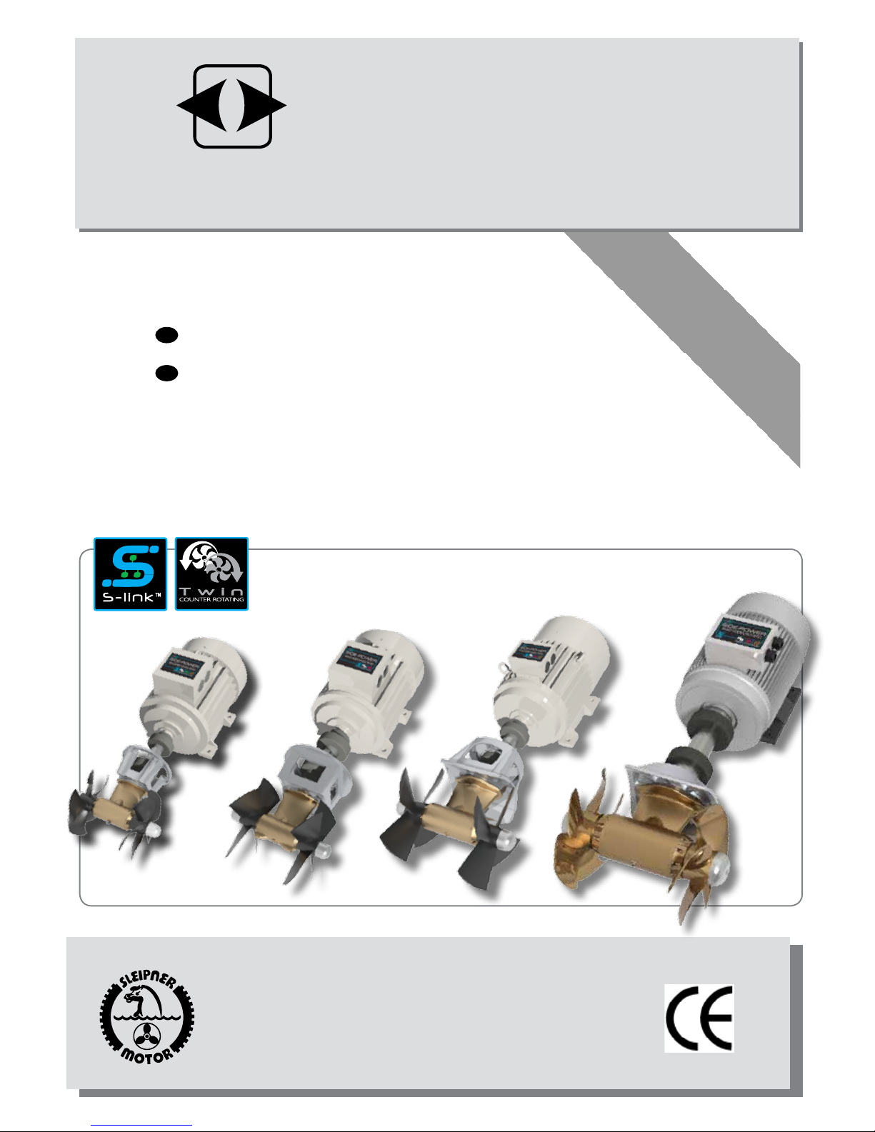
SAC240, SAC300, SAC386,
SAC513, SAC610 Series
AC Thrusters
SIDE-POWER
Thruster Systems
SAC513/SAC610 SAC_Thrusters_ABB_v1_3_April 2014
2
Innhold
NO
INSTALLATION INSTRUCTIONS
Measurements ....................................................................... 3-4
Technical specications .......................................................... 5-6
Planning & important precautions.............................................. 7
Tunnel installation
Positioning of the tunnel / thruster ............................................ 8
How to shape the tunnel ends ................................................... 9
How to prevent drag from tunnel installation ........................... 10
Possible tunnel installation in sailboats ................................... 11
Series production installation................................................... 12
Tunnel installation in a GRP boat ............................................ 13
Thruster installation
Positioning the thruster motor.................................................. 15
Gearhouse and motorbracket ............................................ 16-18
Propeller ............................................................................. 19-21
AC motor ........................................................................... 22-23
Oil tank .................................................................................... 24
Electrical installation
Schematic overview..................................................................25
Wiring diagram .........................................................................26
PDC 101 Proportional Drive Controller.....................................27
Varriable Frequency Drive ........................................................27
Power cable dimensions...........................................................28
Maintenance & service ...........................................................29
Checklist for control of the installation ..................................... 30
Important user precautions ...................................................31
Warranty statement .............................................................. 31
Service centres ..................................................................... 32
Contents
EN
DECLARATION OF CONFORMITY
We, Sleipner Motor AS
P.O. Box 519
N-1612 Fredrikstad, Norway
declare that this product with accompanying
standard remote control systems complies with
the essential health and safety requirements
according to the Directive 89/336/EEC of 23
May 1989 amended by 92/31/EEC and
93/68/EEC.
2
INSTALLASJONSVEILEDNING
Mål ........................................................................................ 3-4
Tekniske spesikasjoner ........................................................ 5-6
Planlegging og viktige hensyn ....................................................7
Tunnelinstallasjon
Plassering av tunnel/truster ...................................................... 8
Hvordan forme tunnelendene .................................................... 9
Hvordan forhindre motstand fra tunnelinstallasjon .................. 10
Alternativer for installasjon i seilbåt ......................................... 11
Installasjon ved serieproduksjon ............................................. 12
Tunnellinstallasjon i en glassberbåt ....................................... 13
Trusterinstallasjon
Plassering av thrustermotor..................................................... 15
Girhus og brakett ............................................................... 16-18
Propeller ............................................................................ 19-21
AC motor og kobling .......................................................... 22-23
Oljetank ................................................................................... 24
Elektrisk installasjon
Skjematikk ................................................................................25
Koblingsskjema ........................................................................26
PDC 101 Proportional Drive Controller.....................................27
Varriable Frequency Drive ........................................................27
Dimensjoner, hovedkabel .........................................................28
Service og vedlikehold...........................................................29
Sjekkliste for kontroll av installasjonen .................................... 30
Viktige forhåndsregler ...........................................................31
Servicesentere ...................................................................... 32
SAMSVARSERKLÆRING
Vi , Sleipner Motor AS
Postboks 519
N -1612 Fredrikstad,Norge
erklærer at dette produktet med tilhørende
standard kontrollsystemer er i samsvar med
helse, og sikkerhetskravene i henhold til Direktiv 89/336/EEC fra 23 Mai 1989, korrigert av
92/31/EEC og 93/68/EEC.
SAC513/SAC610 SAC_Thrusters_ABB_v1_3_April 2014
3
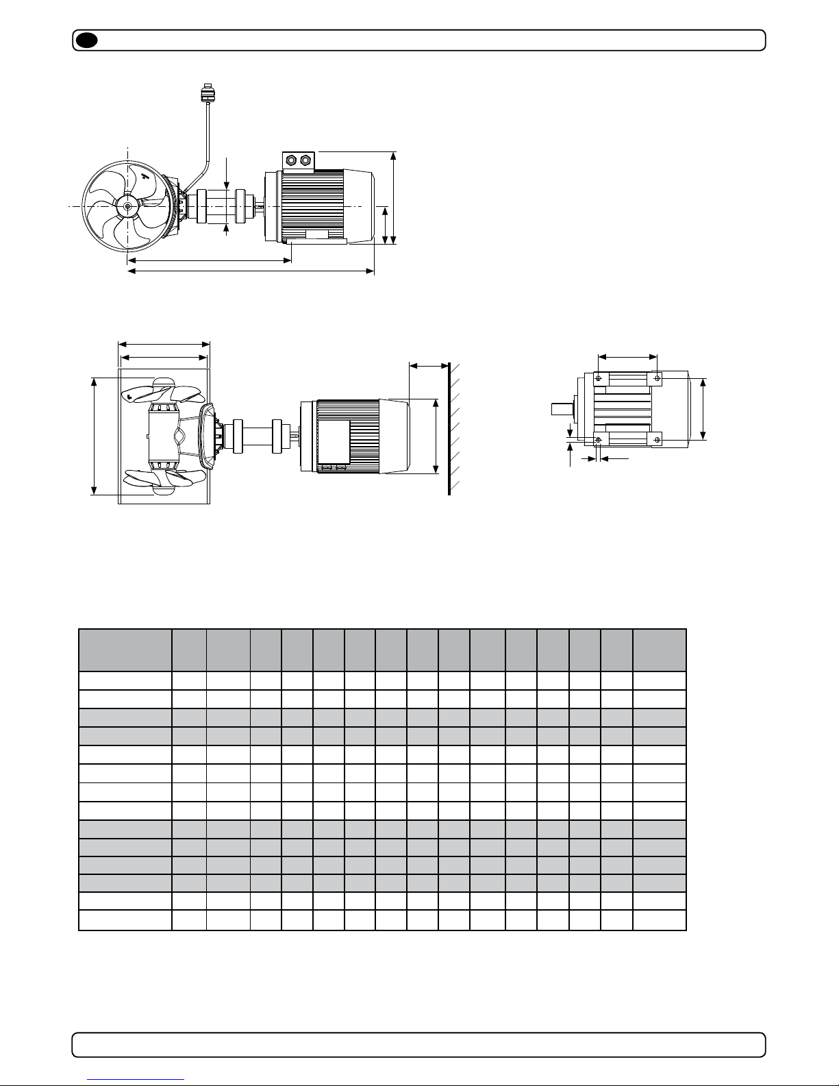
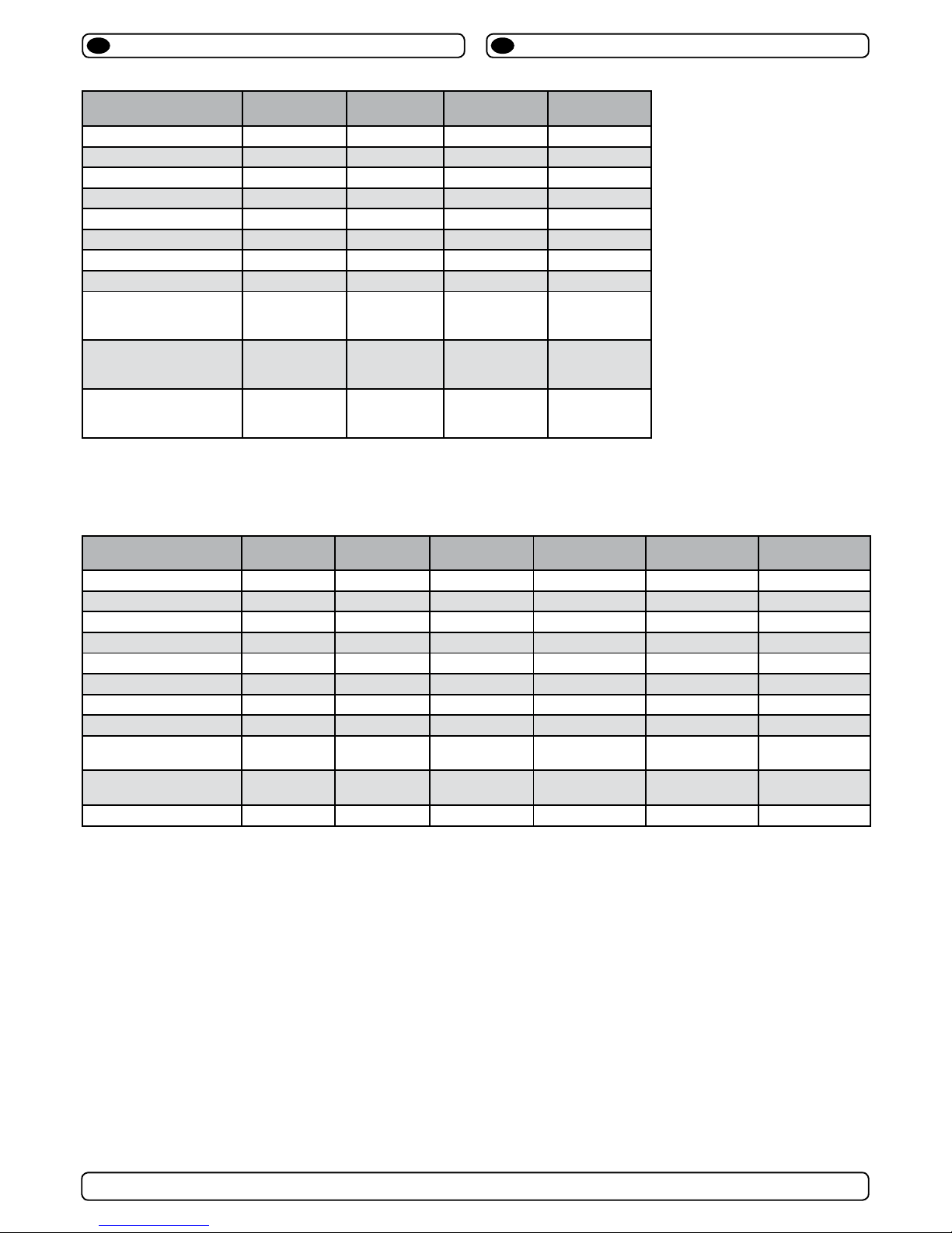
Measurements, thruster
EN
MODEL A*
(mm)
A**
(mm)B(mm)C(mm)D(mm)E(mm)F(mm)G (mm)H(mm)J*(mm)K(mm)L(mm)M(mm)N(mm)
Weight***
(kg)
SAC250-240/240-2 877 1054 250 264 356 100 314 160 380 547 19 15 254 210 92
SAC250-240/240-4 877 1054 250 264 356 100 314 160 380 547 19 15 254 210 92
SAC300-300/300-2 968 1103 300 320 356 120 314 160 380 598 19 15 254 254 108
SAC300-300/300-4 968 1103 300 320 356 120 314 160 380 598 19 15 254 254 108
SAC386-450/450-2 1174 1311 386 406 503 122 364 180 442 736 19 15 279 279 258
SAC386-450/450-4 1174 1311 386 406 503 122 364 180 442 736 19 15 279 279 258
SAC386-450/520-2 1174 1311 386 406 503 122 364 180 442 736 19 15 279 279 258
SAC386-450/520-4 1174 1311 386 406 503 122 364 180 442 736 19 15 279 279 258
SAC513-600/750-4 1326 1460 513 545 685 170 402 200 500 850 25 19 318 305 392
SAC513-750/900-4 1396 1530 513 545 685 170 445 225 550 896 25 19 356 311 462
SAC513-900/1100-4 1468 1602 513 545 685 200 445 225 550 907 25 19 356 311 495
SAC513-1100/1100-4 1505 1638 513 545 685 200 495 250 642 926 30 24 406 349 615
SAC610-1000/1300-4 1635 1797 610 646 685 200 555 280 712 1005 30 24 457 419 770
SAC610-1200/1400-4 1635 1797 610 646 685 200 555 280 712 1005 30 24 457 419 815
* With standard length universal joint shaft
THRUSTER
** With external cooling unit (optional)
*** Weight stated is for complete thruster excluding VFD
1
2
3
4
5
6
7
8
9
10
SAC 513-600/750-4
11.11.2011
1
Designed by
Date
1 / 1
Edition Sh eet
R. Hansen
Material Type Drawing nr
Copyright All rights reserved
Part nr Size Scale
Title
AC Thruster Ø513 750kg
Tolerance
NS-ISO 2768-1
SLEIPNER MOTOR AS
A1
410.000
kg
Weight
3
9
6
Ø
K
L
N
M
AC MOTOR FOOTPRINT
A
J
G
H
E
1
2
3
4
1
2
1
2
3
4
5
4
5
6
A A
B B
C C
D D
4
5
6
C C
D D
F
B
D
C
Min.
150mm
1
2
3
SAC513/SAC610 SAC_Thrusters_ABB_v1_3_April 2014
4
THIS IS A PRO-E DRAWING DO NOT MANUA LLY CHANGE - REVISE PRO-E FILE ONLY
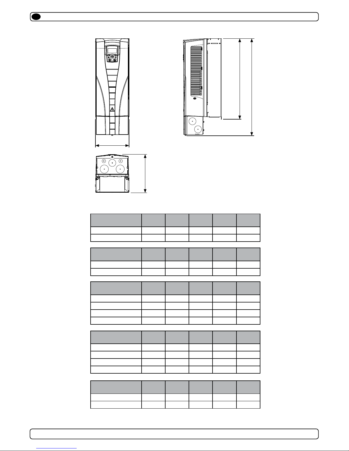
W
D
H1
H2
Measurements, VFD
EN
MODEL H1 (mm) H2 (mm) D (mm) W (mm) Weight (Kg)
SAC250-240/240-2 586 490 203 231 16
SAC250-240/240-4 586 490 203 231 16
VFD Degree of protection: IP21
MODEL H1 (mm) H2 (mm) D (mm) W (mm) Weight (Kg)
SAC300-300/300-2 689 596 203 362 24
SAC300-300/300-4 586 490 203 231 16
MODEL H1 (mm) H2 (mm) D (mm) W (mm) Weight (Kg)
SAC386-450/450-2 689 596 203 362 24
SAC386-450/520-2 888 700 302 400 69
SAC386-450/450-4 689 596 203 362 24
SAC386-450/520-4 689 596 203 362 24
MODEL H1 (mm) H2 (mm) D (mm) W (mm) Weight (Kg)
SAC513-600/750-4 689 596 203 362 24
SAC513-750/900-4 736 602 265 286 34
SAC513-900/1100-4 888 700 302 400 69
SAC513-1100/1100-4 888 700 302 400 69
MODEL H1 (mm) H2 (mm) D (mm) W (mm) Weight (Kg)
SAC610-1000/1300-4 888 700 302 400 69
SAC610-1200/1400-4 888 700 302 400 69
SAC513/SAC610 SAC_Thrusters_ABB_v1_3_April 2014
5
Technical specications
EN
Tekniske data
NO
Motor: AC Electric type (specications next page)
Gear house: Seawater resistant bronze
Gears: Hardened precision gears
Lubrication: 250mm;
Prelled, lifetime lubricated
300/386/513/610mm:
Oil bath from tank (gear oil GL-5) SAE 80W-90
Bearings: Angular contact ball bearing at propellershaft
and combination of ball bearing and needle
bearing at driveshaft.
Material: Seawater resistant bronze, protected with
anodes
Motor bracket: Seawater resistant aluminium
Tunnel: Cross spun with rowing G.R.P tunnel
Steel & aluminum tunnels available at request.
Propellers: 250mm: Composite 5-blade skew "Q-PROP"
300mm: Composite 4-blade kaplan propeller
386mm: Composite 4-blade kaplan propeller
513mm: Bronze 5-blade skew "Q-PROP"
610mm: Bronze 5-blade skew "Q-PROP"
Control system: S-LINK. cables and control panel not included.
Safety: Flexible coupling between AC motor and
driveshaft protects gearsystem against peak
loads.
Motor: AC elektrisk type (spesikasjoner neste side).
Girhus: Sjøvannsbestandig bronsje.
Tannhjul: Herdede presisjonstannhjul
Smøring: 250mm;
Forhåndsfyllt, livstidssmøring
300/386/513/610mm:
Oljebad fra tank girolje GL-5 SAE 80W-90
Lager: Vinklede kulelager på propellaksel og kombinas-
jon av kulelager og nålelager på drivaksel
Material: Sjøvannsbestandig bronse, med anodebeskyt-
telse
Motorbrakett: Sjøvannsbestandig aluminium.
Tunnel: Kryssvevet glassber.
Aluminium og ståltunnel på forespørsel.
Propell: 250mm: 5-blad skew "Q-PROP", kompositt
300mm: 4-blad kaplan propell, kompositt
386mm: 4-blad kaplan propell, komposit
513mm: 5-blad skew "Q-PROP", bronse
610mm: 5-blad skew "Q-PROP", bronse"
Kontrollsystem: S-LINK. Betjeningspanel og kabler er ikke
inkludert.
Sikkerhet: Fleksibel kobling mellom AC motor og girhus
beskytter drivsystemet mot overbelastning
SAC513/SAC610 SAC_Thrusters_ABB_v1_3_April 2014
6
Specications & performance data
Model SAC250-
240/240-X
1)
SAC300300/300-X
1)
SAC386450/450-X
1)
SAC386450/520-X
1)
Typical boat size (m•ft):
17 - 25 • 55 - 84 22 - 30 • 75 - 100 23 - 37 • 75 - 120 22 - 30 • 75 - 100
Tunnel inside diameter:
250mm/9.8" 300mm/11.8" 386mm/15.2“ 386mm/15.2“
Propulsion system:
Counter rotating Counter rotating Counter rotating Counter rotating
Thrust, continous:
240kg/529lbs 300kg/661lbs 450 kg/992 lbs 450 kg/992 lbs.
Thrust, int.:
- - - 520 kg/1146 lbs.
Motor output continous:
14 kW/19 Hp * 16,2kW/22Hp * 28 kW/38 Hp 28 kW/38 Hp
Motor output int.:
- - - 35kW/48Hp
Voltage
220/240 - 380/400 220/240 - 380/400 220/240 - 380/400 220/240 - 380/400
Max. current, continous
220/230V:
380/400V:
47,5A / 45A
27,5 A / 26A
63,5A / 61A
37A / 35A
100A / 96A
58A / 55A
100A / 96A
58A / 55A
Max. current, intermittent
220/230V:
380/400V:
- - 125A / 120A
73A / 69A
Generator load max
18,5 KVA 22 KVA 37 KVA 47 KVA
1)
-2 for 220/240V version , -4 for 380/400V version
2)
AC motor output
Model SAC513-
600/750-X
1)
SAC513750/900-X
1)
SAC513900/1100-X
1)
SAC5131100/1100-X
1)
SAC6101100/1300-X
1)
SAC6101200/1400-X
1)
Typical boat size (m•ft):
27-43
• 90-140 30-46 • 100-150 32-48 • 105-155 34-49 • 110-160 37-49 • 120-160 40-52 • 130-170
Tunnel inside diameter:
513mm/20" 513mm/20" 513mm/20" 513mm/20" 610mm/24" 610mm/24"
Propulsion system:
Counter rotating Counter rotating Counter rotating Counter rotating Counter rotating Counter rotating
Thrust, continous:
600 kg/1323 lbs. 750 kg/1653 lbs. 900 kg/1984 lbs. 1100 kg/2425 lbs. 1000 kg/2405 lbs 1200 kg/2646 lbs.
Thrust, intermittent:
750 kg/1653 lbs. 900 kg/1984 lbs. 1100 kg/2425 lbs. 1100 kg/2425 lbs. 1300 kg/2866 lbs. 1400 kg/3086 lbs.
Motor output cont.:
27 kW/38Hp 37 kW/53 Hp 49 kW/67 Hp 68 kW/93 Hp 54 kW/74 Hp 61 kW/83 Hp
Motor output int.:
37 kW/53 Hp 49 kW/67 Hp 68 kW/93 Hp - 69 kW/94 Hp 80 kW/109 Hp
Voltage
380/400 380/400 380/400 380/400 380/400 380/400
Max. current, continous
380/400V:
72A / 68A 88A/84A 103A / 98A 133A / 126A 111A / 105A 124A / 118A
Max. current, intermittent
380/400V:
88A/84A 103A / 98A 133A / 126A
- 139A / 132A 161A / 153A
Generator load MAX
50 KVA 64 KVA 86 KVA 86 KVA 90 KVA 105 KVA
Technical specications
EN
Tekniske data
NO
SAC513/SAC610 SAC_Thrusters_ABB_v1_3_April 2014
7
The recommendations made in this manual are to be used as starting guidelines only, and Sleipner Motor AS
(Side-Power) strongly recommend that prior to installation, advise should be obtained from a naval architect familiar with the particular vessel brand and potential regulations/classifications regarding the vessel.
When installed in boats approved or classified according to international or special national regulations, the installer is responsible for following the demands in accordance with these regulations/classification rules (electrical/
mechanical). The instructions in this guide can not be guaranteed to comply with all different electric/mechanic
regulations/classification rules.
Prior to installation, it is important that the installer reads this guide to ensure necessary acquaintance with this product.
This manual is intended to support educated / experienced staff and is therefore not sufcient in all details for the correct installation.
If the height/length in the room you are installing the Side-Power is limited, the Side-Power can be installed at different angles
The motor must be handled carefully.
Beware to keep installation within adviced measurements. No part of the propeller or gearhouse must be outside the tunnel.
The motor, its components (VFD, electric junction boxes etc.) or other joints and control cables must be mounted so that they will keep
dry at all times.
We advice to paint the gearhouse and propellers with antifouling. NB! Do not paint the anodes, sealings or propellershafts.
Do not nish the inside of the tunnel with a layer of gelcoat / topcoat or similiar. It is only room for a thin layer of primer and two layers
of anti-fouling between the tunnel and the propellers.
NB ! Faulty installation of the tunnel, thruster or panel will render all warranty given by Sleipner Motor AS void.
Planning and important precautions
EN
Anbefalingene i denne manualen er å anse som grunnleggende retningslinjer, og Sleipner Motor AS (Side-Power)
anbefaler sterkt at råd fra en marinearkitekt med erfaring fra den aktuelle båt typen og eventuelle klassekrav
innhentes før installasjonen påbegynnes. Ved installasjon i klassede fartøy eller i fartøy som skal oppfylle spesielle
nasjonele krav/regler (mekaniske og/eller elektriske) er installatøren ansvarlig for at disse følges. Instruksjonene i
denne manualen kan ikke garanteres å oppfylle alle krav og hensyn til slike regler.
Før installasjon er det viktig at den/de som utfører jobben leser manualen for å gjøre seg kjent med produktet
Denne manualen er laget med henblikk på kvalisert personell, og inneholder derfor ikke alle nødvendige detaljer for en komplett
installasjon
Hvis høyden/lengden i rommet er begrenset, kan thrusteren monteres i forskjellige vinkler
Motoren må behandles forsiktig
Pass på å utføre installasjonen innenfor de anviste mål. Ingen del av propell eller girhus må stikke utenfor tunellen.
Motoren med dens tilhørende komponenter ( VFD, koblingsskap etc) og kontroll kabler må monteres slik at de er tørre til enhver tid.
Vi anbefaler at girhus og propeller behandles med bunnstoff. NB! Mal ikke anoder, pakninger eller propellaksler.
Bruk ikke gelcoat / topcoat eller lignende på innsiden av tunellen. Det er kun plass for et tynt lag primer og to lag bunnstoff mellom
tunellen og propellene.
NB ! Feilaktig installasjon av tunell, thruster eller panel vill oppheve enhver garanti gitt av Sleipner Motor AS.
Planlegging og viktige hensyn
NO
DO NOT connect any other control equipment to the S-link controlled products except Side-Power original S-link products
or via a Side-Power supplied interface product made for interfacing with other controls. Any attempt to directly control or at
all connect into the S-link control system without the designated and approved interface, will render all warranties and responsibilities for the complete line of Side-Power products connected void and null. If you are interfacing by agreement with
Sleipner and through a designated Side-Power supplied interface, you are still required to also install at least one original
Side-Power control panel to enable efcient troubleshooting if necessary.
Koble IKKE til annet kontrollutstyr til S-link utstyrte produkter enn Side-Powers originale S-link produkter eller via et Side-
Power interface levert av Side-Power laget spesikt for dette formål. Ethvert forsøk på direkte kontroll eller på noen måte å
koble seg til S-link systemet uten det spesikke interface, vil gøre enhver garanti og ansvar fra Sleipner Motor AS ugyldig.
Hvis det benyttes et interface etter godgjenning fra Sleipner Motor AS er det fremdeles påkrevet med minst ett originalt
Side-Power kontrollpanel for å muliggjøre effektiv feilsøking hvis påkrevet.
SAC513/SAC610 SAC_Thrusters_ABB_v1_3_April 2014
8
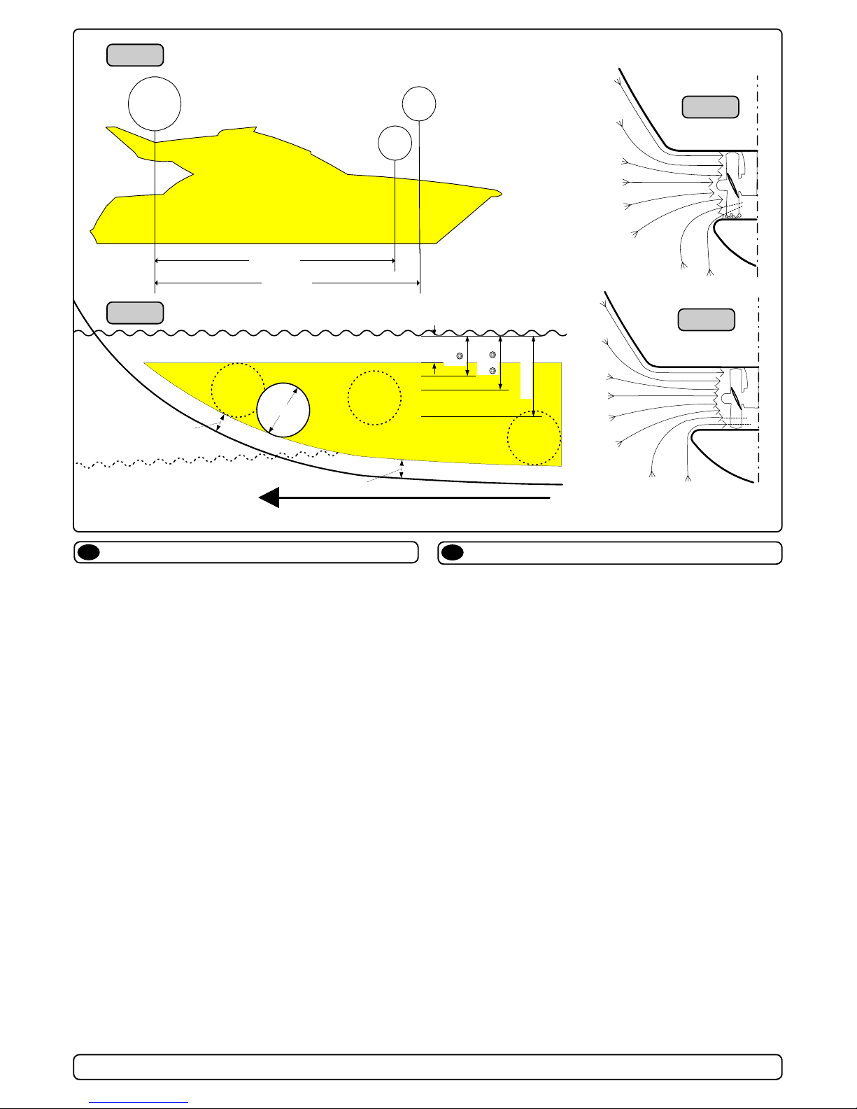
The Thruster should be as far forward as possible (Fig. 1)
Because of the leverage effect around the boats pivot point, it is
very important for the thrusters actual effect in the boat to get it as
far forward as possible. The relative distance change from the boats
pivot point to the thruster will be the change of actual thrust for the
boat.
Example :
A: 100kg thrust x 11m leverage = 1100kgm torque to rot. the boat
B: 100kg thrust x 10m leverage = 1000kgm torque to rot. the boat
In position A you will get 10% more thrust to turn the boat around.
The thruster should be placed as deep as possible (Fig. 2)
The tunnel should be placed as deep as possible for two reasons:
1. Thrust will be reduced dramatically due.
2. To get as high as possible a water pressure to get maximum
efciency from the propeller.
Generally the top of the tunnel should be a minimum of 1/2 x the
tunnel diameter below the waterline. This is an absolute minimum
and we recommend that it is at least 3/4 x tunnel diameter ()
below the waterine. A really good distance is about 1/1 x tunnel
diameter () below the waterline.
When you get the top of the tunnel 30-35 cm* / 1 feet below the
surface, other factors should be considered more important, i.e.
moving the thruster further forward.
Optimal tunnel length
If the tunnel gets to long, the friction inside will reduce the water
speed and thereby the thrust.
If the tunnel gets to short (normally only in the bottom section of
the tunnel) you can get cavitation problems as the water will not
have had time to “straigthen” itself before reaching the propel-
ler (Fig. 3/4). This cavitation will reduce performance as well as
creating a lot of noise.
The optimal tunnel length is 2 to 4 x tunnel diameter and you
should avoid tunnels longer than 6 to 7 times the tunnel diameter
as the performance reduction is then clearly noticeable.
Positioning of the tunnel / thruster
EN
Plassering av tunnel og thruster
NO
Tunnelen bør plasseres lengst mulig frem i baugen (Fig. 1)
For å oppnå mest mulig moment rundt båtens dreiepunkt, er det
meget viktig å plassere tunnelen så langt fremme som mulig.
Avstanden fra båtens dreiepunkt til thruster vil ha stor betydning
på thrusterens effekt.
Eks.:
A: 55kg skyvekraft x 11m moment = 605kgm skyvekraft
B: 55kg skyvekraft x 10m moment = 550kgm skyvekraft
Posisjon A vil gi 10% mer skyvekraft til rotasjon.
Tunnelen skal plasseres dypest mulig (Fig. 2)
Tunnelen skal plasseres så dypt som mulig av to grunner:
1. Så luft ikke suges ned i tunnelen og ødelegger skyvekraften.
2. Ved å øke vanntrykket jobber propellen mer effektivt.
Hovedregelen er at tunnelen skal plasseres minimum ½ x tunnelen dia. under vannlinje. Anbefalt dybde er minst ¾ x dia. under
vannlinje (). Når tunnelen er plassert 33-35 cm under vannlinjen
bør andre faktorer vurderes som viktigere, d.v.s. å plassere tunnelen lengre frem.
Optimal tunnel lengde
Dersom tunellen blir for lang vil friksjonen i tunellen reduser vannhastigheten og derved effekten.
Dersom tunellen blir for kort (normalt bare i nedre del av tunel-
len) kan det oppstå kavitasjons problemer da vannet ikke har tid
/ av-stand til å «rette opp strømningsretningen» før det treffer
propellen (Fig. 3&4). Denne kavitasjonen vil redusere effekten og
lage mye støy.
Den optimale tunell lengden er 2 til 4 ganger tunell diameteren
og dersom tunellen blir så mye som 6 til 7 ganger diameteren i
lengde vil effekt tapet bli klart merkbart.
A = 11,0m
B = 10,0m
A
B
Pivot
point
m
i
n
.
1
/
3
Ø
Ø
m
i
n
.
1
/
3
Ø
3/4Ø
☺
1/1 Ø
☺
☺
30 - 35 cm*
min.
1/2Ø
Fig. 1
Fig. 2
Fig. 3
Fig. 4
SAC513/SAC610 SAC_Thrusters_ABB_v1_3_April 2014
9
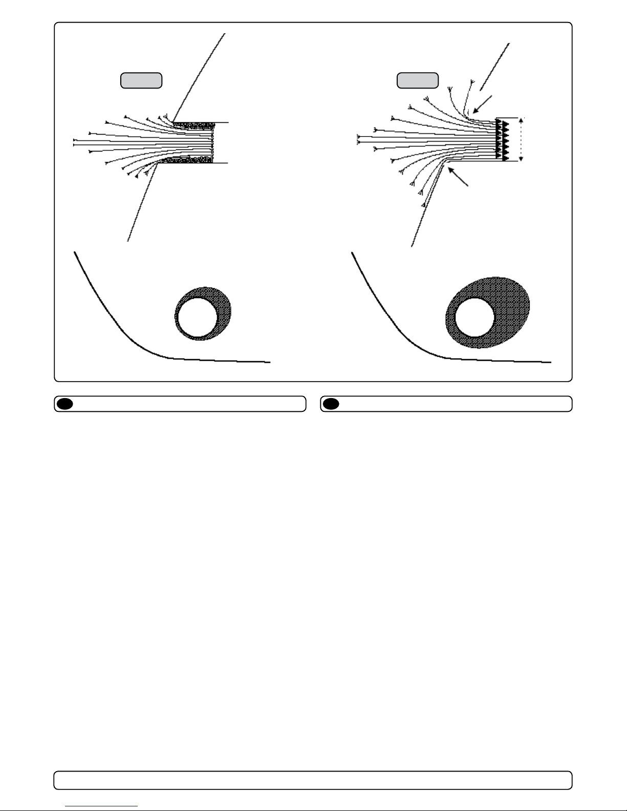
Rounded tunnel ends will maximize thrust and minimize noise.
We recommend to round the tunnel connection to the hull-side as
much as possible.
The optimum rounding has a radius of 10% of the tunnels diameter.
Important advantages over sharp tunnel to hull connections are:
1. The rounded tunnel end will prevent creation of turbulence /
cavitation that will come from a sharp tunnel end when water
passes by fast, thereby preventing a double negative impact on
the thrust and noise level (Fig. 1&2).
- The turbulence / cavitation blocks the outer area of the tunnel
and thereby reduces the effective tunnel diameter and thrust.
- The turbulence / cavitation hits the propeller and thereby
reduce the propellers performance and creates noise.
2. The curved tunnel end makes the thruster take water also from
along the hull-side, creating a vacuum that will suck the boat
sideways and thereby give additional thrust (Fig. 3&4).
With a sharp tunnel end, the thruster will be unable to take
water from along the hull-side, and you will not get the desired
vacuum and additional thrust.
This "free" additional thrust can in optimal installations be as
much as 30 - 40% of the total thrust.
NB! A Sidepower thruster propeller does not cavitate at working
speed so that all cavitation and cavitation noise in the tunnel will be caused by the tunnel installation.
NB! Even if it is not possible to make the perfect rounding, it is
very important to round the tunnel end as much as possible.
A angled tunnel to hull connection will also do much of the
same job as a rounded connection (see page 20, Fig. 1b&1d).
Tunnel ends
EN
Fig. 2
Fig. 4
Fig. 1
Fig. 3
R = 0,1 x D (10%)
R = 0,1 x D (10%)
D
Tunnelåpninger
NO
Avrundede åpninger vil minke støy, og maksimere effekt.
Vi anbefaler å avrunde tunnelåpningene mest mulig.
Den optimale avrundingen har en radie som er 10% av tunnelens
diameter.
Hvorfor er en avrundet tunnelåpning så viktig?
1. En avrundet tunnelåpning vil forhindre at det oppstår turbulens / kavitasjon, noe som vil oppstå ved en installasjon med
skarpe kanter. Turbulensen forårsaker mer støy, og begrenser
skyvekraften.
- Turbulensen / kavitasjonen blokkerer tunnelen og svekker
skyvekraften.
- I det kavitasjon og turbulens når propellen påvirkes ytelsen til
denne og øker støyen.
2. En avrundet tunnelåpning gjør også at thrusteren suger vann
langs skroget på båten. Dermed oppstår det et lavtrykk som
vil hjelpe å suge båten i dreieretningen. Med skarpe åpninger
klarer ikke thrusteren å suge vann langs skroget, og lavtrykket
uteblir. Så mye som 40% av skyvekraften har blitt målt til å
ligge her på noen installasjoner.
NB! Propellene til Side-Power thrustere kaviterer ikke på arbeid-
shastighet, så kavitasjon og støy som oppstår som følge av
kavitasjon, skapes av tunnelinstallasjonen.
NB! Selv der en perfekt avrunding ikke er mulig er det viktig å
runde av kantene så mye som mulig, en tunnelåpning med
skråkant vil ha stor effekt fremfor en med skarpkant (se side
20, ill. 1b & 1d).
SAC513/SAC610 SAC_Thrusters_ABB_v1_3_April 2014
10
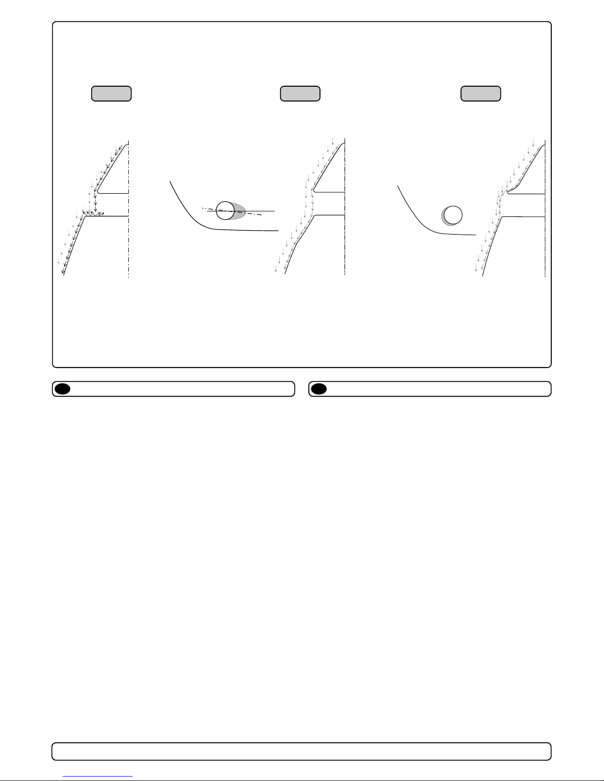
A possible problem in sailboats or fast powerboats, is that they
get a drag from the back face of the tunnel, as this becomes a
“at” area facing the water ow (Fig. 1).
This can also create problems with the thruster spinning (passive)
and making noise while sailing or driving the boat with water being pushed through the tunnel at high speed.
This can be solved in two different ways, depending on what is
possible or more easy to do.
1. The best solution which normally reduces the drag most, is to
make a recess in the hull at the back of the tunnel.
Thereby the back face is gone and about all the drag (Fig. 2).
The depth and shape of this recess will depend on the boat.
Basically you should not see the back face of the tunnel when
standing directly in front of the tunnel at the angle of the boats
centreline.
The angle up or down backwards of the insert in the hull, de-
pends on the hullshape, but normally it is angled slightly down
because of the waterow on this area of the hull.
2. The drag will also be reduced a lot, especially in fast power
boats, by making a deector / spoiler in front of the tunnel.
This will push the waterow out from the hull so that most of it
passes by the back face of the tunnel (Fig. 3).
The shape and size of this deector will depend on the hull
shape. Basically you should not see the back face of the tunnel
when standing directly in front of the tunnel at the angle of the
boats centreline.
The easiest way of making this is to let a part of the tunnel
stick out in the lower forward area of the hole, and use this as
a support to mould a soft curve / spoiler shape.
Remember to still round the tunnel ends as much as possible to
get optimum thruster performance and minimum noise.
More information on how to practially do this on pages 6.
Prevent drag from tunnel
EN
Motstand forårsaket av tunnel
NO
Et mulig problem for seilbåter eller meget hurtiggående båter er
motstand i tunnelen. Aktre ende på tunnelen vil være en liten lod-
drett ate mot vannstrømmen som skaper uønsket motstand.
Denne aten kan også forårsake problemer med at vann føres
inn i tunnelen under seilas, eller kjøring i høy fart og får da propellen til å rotere, dette skaper uønsket støy.
Det er to mulige løsninger på problemet, avhengig av hva som er
enklest å få til på båten.
1. Den løsningen som vanligvis reduserer motstanden mest er å
lage en fordypning i skroget i aktre ende av tunnelåpningen.
Den loddrette aten vil da forsvinne og dermed motstanden.
Hovedregelen å følge er at bakkanten av tunnelen ikke skal
synes når man står rett foran båten og titter akterover langs
båten senterlinje. Dybden, utformingen og vinkling av fordypningen avhenger av båttypen, og hvordan vannet følger skro-
get, men de este båter vil være tjent med en fordypning som
vinkler lett nedover (Fig. 2).
2. Motstanden vil også reduseres av en spoiler i forkant av
tunnelen. Spoileren fører det meste av vannstrømmen rundt
og forbi tunnelen. Størrelsen og utformingen på spoileren
avhenger av båten. Hovedregelen er at bakkanten av tunnelen
ikke skal synes når man står rett foran båten og titter akterover
langs båten senterlinje. Den enkleste måten å lage spoileren
på er å la tunnelen stikke ut i forkant av tunnelen, og forme
spoileren opp mot den (Fig. 3).
Det er alltid viktig å avrunde tunnelåpningene mest mulig for å
motvirke støy og for å få mest mulig effekt av thrusteren.
Mer informasjon om dette på side 10.
☺☺
☺☺
☺
��
��
�
Fig. 2Fig. 1 Fig. 3
☺☺
☺☺
☺
 Loading...