

Sidekick SK-8RG Owner's Manual
1
SIDEKICK
Automatic
Film Processor
Model SK-8RG
Owner’s Manual
US PATENT RE 34,188
Please record the Serial No. ____________ and date of Purchase __________
Please mail in your warranty card.
TABLE OF CONTENTS
2 Description 9 Chemicals
2 Setting up 9 Processes other
4 Processing 10 Push processing
5 Drying 10 Disc processing
6 Reel loading 11 4x5 processing
7 Special functions 12 Automatic replenishing
7 Maintenance 15 Service
8 Alarms and messages 18 Parts list
8 Hints 20 Phone #’s & Log
WARRANTY
Each Photo-Therm product is produced under rigid quality control standards. This
unit is fully warranted for a period of one year from date of purchase. Photo-Therm
110 Sewell Ave Trenton NJ 08610 USA Tel 609 396-1456 Fax 609 396-9395.

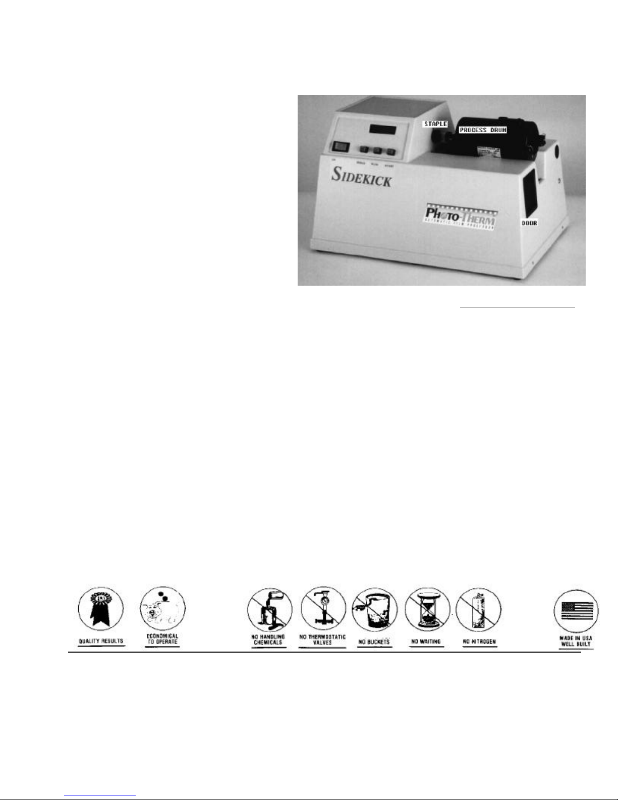
DESCRIPTION
The SK-8RG automatic processor accurately tempers each solution, one at a time. This
design breakthrough allows B/W processing at 75 oF and then immediately afterwards
slide processing 100 oF. Tempered water is not needed. Long warm-ups are not
required.
All the solution bottles for processing color slides, color negatives and Black and White
negatives are constantly connected. The operator just selects the process. The unit
pumps the proper chemical from any of the 18 reservoir containers, quickly heats the
small volume needed to the correct temperature and starts processing. As it processes
one solution it prepares the next solution. At the end of the process cycle it automatically
flushes itself clean, preparing itself for the next process.
The SK-8RG is compact (26” wide by 14” high by 16” deep). The process drum is
removable for loading in a dark box or bag. The SK-8RG can process 8 rolls of 35, 5 rolls
of 120/220, 8 sheets of 4x5 or 18 disc films at one time. Two chemicals can be
automatically saved from each process for silver recovery or reuse. Fresh developer is
used for quality. The standard processes are pre-programmed, but the developer time
can be easily changed when desired.
The SK-8RG protects the film from possible operator errors. It has an interactive
computerized display that prompts and informs the operator what it is doing. Possible
operator errors are also minimized because, chemical lines do not have to be switched
nor must volumes of solutions be measured.
SETTING UP THE UNIT
The unit comes packed in 2 boxes. Make sure you received the following:
... Main processor SK-8RG
... 8-reel and a 4-reel black processing drum with lids
... 8-reel and a 4-reel spindle
... 10 plastic film reels
... Spacer 2-roll (white fat donut)
... Turbo dryer tube. (White plastic 4” diameter 11” long)
... Coil of ¼” flexible tubing
... Power cord
... Six ½ gal. (2 liter) solution bottles with fittings
... Six 1 gal. bottles
... Two Metering valves
... Two 1 Gal replenishing bottles with bladders
... Two 1 gal. collapsible bottles
... Water bottle (5 gal) with float valve
... “Ice Maker” kit to connect water bottle to water pipe
... Dump bottle (5 gal) with level sensor and cap with
3” gray plastic fitting to hold two dump tubes
... 10 Film Clamps for 120/220 film.(white curved plastic pieces)
... Plug to seal COUPLING when FLUSHING
... Syringe of silicone grease
... Allen wrench (1/16”) for bushings
... Magnetic stirrer. A white “pill” (3/8” x 1”)
... Permanent marker
... Piece of Scotch Brite
tm
... Set-up video
... This instruction book
2
SETTING UP THE UNIT Cont.
Place the unit on a flat level surface. Lift up the side and cut away and discard the two
visible nylon straps from the bottom of the unit. These straps hold the pumps secure for
shipping and must be removed for the pumps to work.
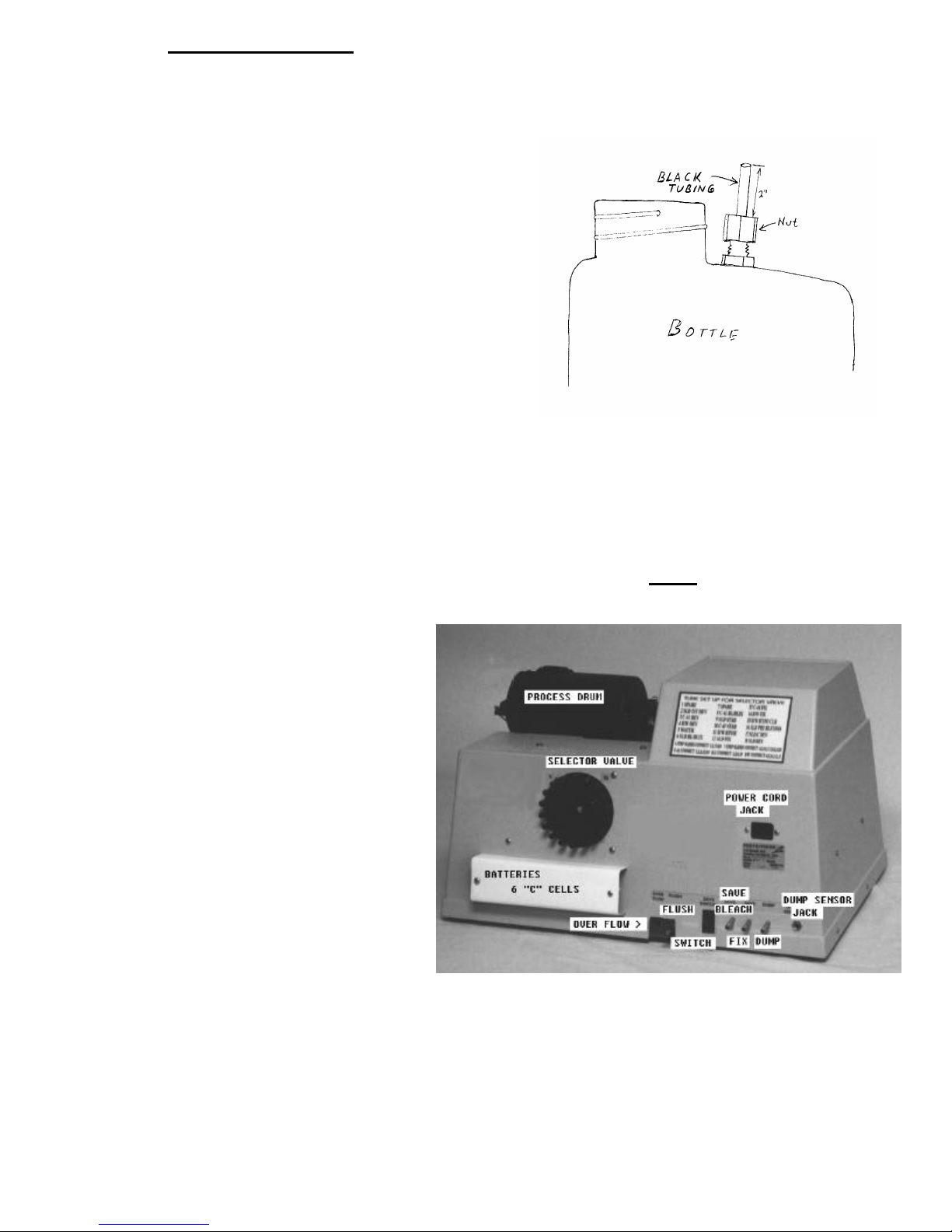
Prepare the solution bottles. a) Loosen
NUT. b) push in notched end of the ¼ OD
black tubing through fitting to bottom of
bottle. Leave about 2 inches (5 cm)
exposed. c) Hand tighten nut. d) Rinse out
bottle. You can use the collapsible bottles
for developers, they will extend chemical
life because there is no air interface.
Use the marker pen to label each bottle and
lid with the chemical it contains. Cut a
piece of clear flexible tubing long enough
to run from the bottle to the back of the
machine. RUN THE TUBING STRAIGHT
DOWN from the back of the machine. After about a foot, the tubing can run in any
direction Allow about 2 feet (60 cm.) extra for slack. Label both ends of the tubing with
the chemical name. Slip one end over the proper tube and the other end over the
exposed black tubing of the solution bottle. The 5 gal. water bottle connects to the
WATER (#5) tube.
IMPORTANT. The solution source bottles must be located below the processor.
The 5 gal. water bottle, which
has a float valve near its lid,
holds the water that will be
used for processing and
internal cleaning (FLUSHING)
of the unit. You can manually
fill the bottle. Use regular tap
water, not de-ionized or
distilled water. You can
connect the bottle to a cold
water pipe for automatic filling
with the “ice maker” kit. TURN
OFF THE WATER AT THE
SOURCE WHEN THE MACHINE
IS NOT IN USE.
The DUMP bottle comes with a
level sensor that should be plugged into the DUMP SENSOR jack on the back of the unit.
IT WILL SENSE IF YOU HAVE ENOUGH ROOM FOR A 2 or 4 ROLL RUN ONLY. The bottle
must be emptied if you are doing a 6 or 8 roll run. If a plumbed-in drain is available, use
it.
3
SETTING UP THE UNIT Cont.
There are five drain outlets in the back of the unit:
1. DUMP - For spent chemistry. Connect to DUMP bottle or plumbed-in drain.
2. FLUSH - Disposes of spent FLUSH water. Connect to DUMP bottle or drain.
3. SAVE FIX - Recovers the solution to be saved. Active only when SAVE switch is
on (red is showing). Connect to separate bottle.
4. SAVE BLEACH - Recovers solution to be saved. Active when SAVE switch is on.
Connect to separate bottle.
5. OVERFLOW - DO NOT CONNECT. If solution comes out of this outlet, check your
FLUSH tubing for proper installation.
Push the flexible tubing over the stainless tubes of these outlets (no more than 3/4”).
VERY,
VERY,
IMPORTANT!
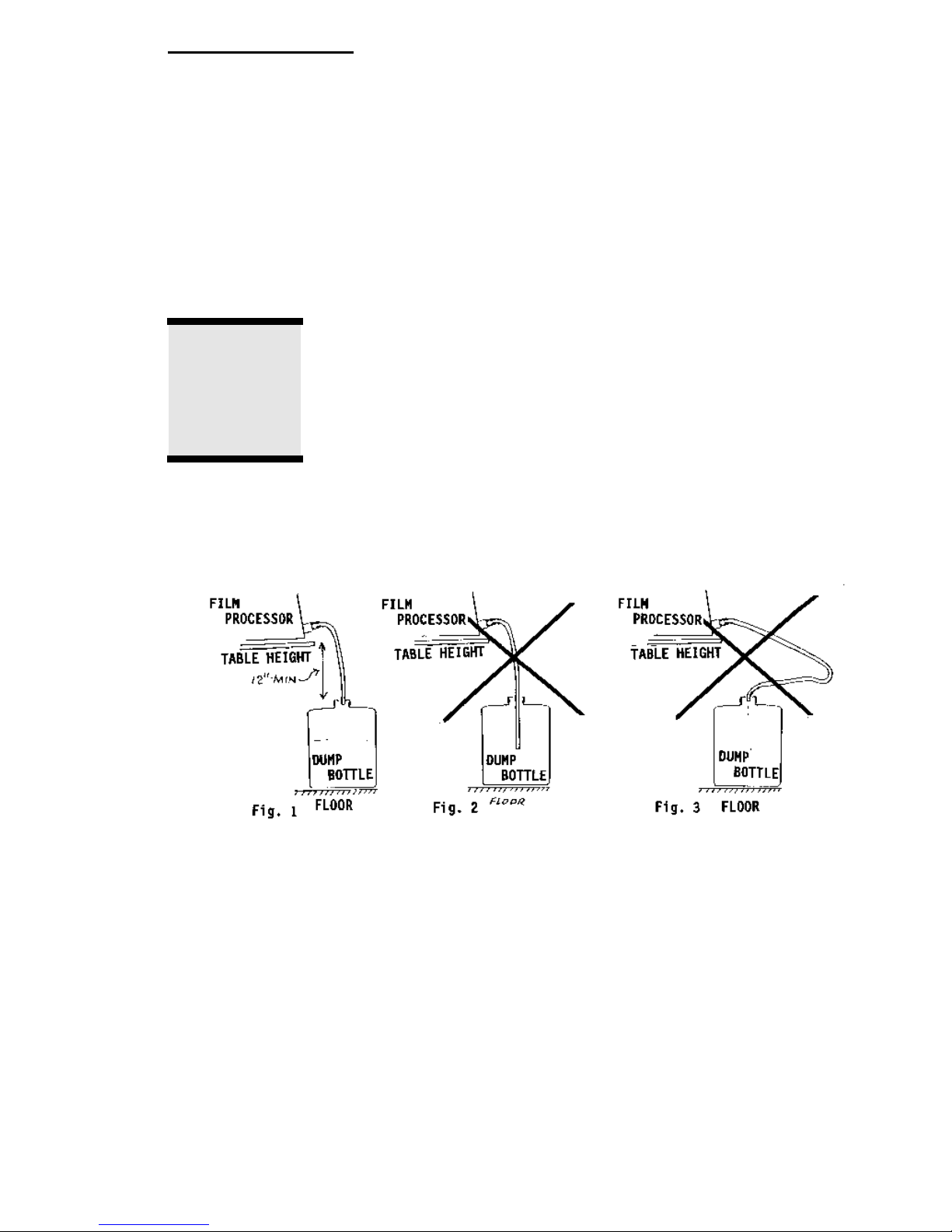
Run tubing directly to DUMP bottle. (Fig. 1)
Cut off unneeded length of dump tubing. (Fig. 1)
Run the DUMP and the FLUSH tubing separately into the 3” gray
fitting on the DUMP bottle. Do not put a third tubing into the same
fitting.
Do NOT run tubing inside DUMP bottle. (Fig. 2). Allow at least 12” drop between unit and
DUMP bottle.
Position DUMP bottle close to unit. (Fig. 1)
Open the DOOR by lifting up from the bottom and pulling out. Place the magnetic stirrer
(white pill) in the exposed heat tank. Carefully push the stirrer with a pencil until it is
magnetically caught near the back right corner of the tank. Turn SIDEKICK on and
check if the stirrer is turning.
Put in six Alkaline “C” Cells in the battery holder. This will allow the unit to continue after
a power failure and protect it against power surges. Plug the power cord into a 120 Volt
AC 15 Amp. (regular domestic) outlet.
4

PROCESSING
In a dark box, load the film on the reel (see REEL LOADING). Slide the reel on the spindle.
If there is room on the spindle, use the SPACER (goes on last) to conserve chemistry.
Place the spindle inside the PROCESS DRUM. Cover the spindle with the lid (one side is
shaped to go over the spindle). Clip the tank together. You are now light tight.
Push the PROCESS TANK to the left in the TROUGH till the SNOUT seats itself inside the
COUPLING. The two stainless pins of the spindle should go on opposite sides of the
STAPLE on the rotate motor.
Look to make sure you have enough solution in the chemical bottles. Empty the DUMP
bottle. Turn the unit ON. Use PLUS to select the type of film you are processing. Push
START to begin the process.
The unit will ask you how many rolls (35 mm) are being processed. Use “PLUS to select :
“2” for 1 or 2 rolls of 35mm or 1 roll of 120/220. Use SPACER.
“4” for 3 or 4 rolls of 35mm, 2 rolls of 120/220 or a 4x5 sheet film holder.
“6” for 5 or 6 rolls of 35mm, 3 rolls of 120/220 or 2 4x5 holders (8 sheets). Use SPACER
“8” for 7 or 8 rolls of 35mm, 4 or 5 rolls of 120/220.
The unit uses about 3 ½ oz (105 ml) of each solution per 35mm roll.
If you want to change the developing times see PUSH PROCESSING.
The unit will load the first solution into the internal heating tank, heat it to the proper
temperature, warm the processing drum with warm air and then start the process
automatically. As the unit is processing one solution it prepares the next solution. The film
DRUM has an independent temperature sensor that controls the warm air blowing on the
DRUM. This fine tunes the solution to an accurate temperature for very consistent
results.When one solution is finished it is drained out and the prepared solution in the heating
tank is pumped into the DRUM. The same procedure is repeated for all the necessary
solutions. The unit will signal at the end of the wet processing. Remove the PROCESS DRUM.
Insert the PLUG in the COUPLING and wipe out the TROUGH with a paper towel.
DRYING
Up to 4 rolls of 35 mm film can be dried in the included TURBO DRYER on reels. The film
can also be dried any other way. The base of 120 film is too thin for drying on a reel, and
must be dried by other means. Disc drying requires an accessory dryer (Part AF-DD).
Place the TURBO DRYER vertically in the TROUGH so that the cut away portion of the
TURBO DRYER covers the air vent in the side of the TROUGH. Shake out each reel 4
times over a sink with a vigorous snap of the wrist to remove excess solution. Replace
the reels on the spindle and put the spindle in the TURBO DRYER
Push START to begin drying. The unit will FLUSH itself as it is drying. The unit MUST BE
ALLOWED TO FLUSH itself after every processing run. The required drying time will vary
with the amount of film and the relative humidity of the room. If the film is not fully dry
when the dryer stops (15 min.), dry again. Rinse all reels, spindle and drum with COLD
water. Room air dry - hot air may distort the parts. RINSE, DO NOT IMMERSE THE DRUM.
If you get drying marks, try the following: a) use distilled water for the last step. b) dilute
the wetting agent or stabilizer. c) use softened water. d) external rinse in distilled water.
e) squeegee and hang up to dry. Film with drying marks can be re-rinsed and dried
again.
5

REEL LOADING
The plastic ratcheting reels can be adjusted to hold different sizes of film. Simply hold
the reel in both hands, making sure that the outer spiral groove (near the ball bearings) is
on top and facing you.
Twist the right half of the reel clockwise until you hear a click. The two halves can then
be pulled apart. There are 3 “keyed” positions on the reel hub. The narrowest position is
for 35mm or 126, the second for 127, and the widest for 120/220.
Insert the leading end of the film, emulsion down, into the outer spiral groove of the reel
and a few inches past the ball bearings. With both hands on the reel twist the right half
and the left half in opposite directions. You may have to assist the film feeding by placing
the thumb, of your forward moving hand, on the outside of the film.
Keep feeding the film until the end clears the ball bearings.
Any Paterson tm reels will work. They are available at most photo stores. Contact PhotoTherm if you prefer to use different style reels.
35 MM FILM Cut off the film leader. Clip the corners of the leading end to make feeding
easier. Cut a “V” into the leading end as shown in sketch. 35 mm film can be started in
the light, but must be fed into the reel in the dark. When you reach the end of the film use
scissors to cut it away from the film cassette. Do not tear the film. An uneven tear may
cause the film to come off the reel.
120/220 FILM. Separate the tape from the backing paper and fold it back over the film.
This will stiffen the end of the film. Load the taped end into the reel. Feed until the back
end is passes the ball bearings.
Bend the 120 Film Clamp and place it over the end of the film into the grooves of the reel,
close to the ball bearings, as shown above. Add a second film clamp on top of the first
one. For extra assurance use a 1 in. piece of leader tape to bond the end of the film to
the film clamp.
Mount the 120 reels in the center of the spindle.
6
 Loading...