

Siddons Solarstream MAHRW015WAA Owner's Manual

www.siddonssolarstream.com
To be read in conjunction with the
Installation and User Manual for models:
ELECTRONIC SPLIT HEAT PUMP
OWNER'S MANUAL
For externally coiled tanks with
refrigeration line connections
Model MAHRW015WAA
AIR TO WATER HEAT PUMP
264SSAD, 264SSBD
327SSAD, 327SSBD

Notice
1.1 Save this manual for future reference.
1.2 In order to use this product better and more safely, please read this manual carefully before
installation and initial operation.
1.3 Children or persons with physical, sensory or mental disability should not play with nor operate
this appliance.
1.4 This appliance must be installed by qualified and experienced technicians/tradespeople.
Improper installation of this appliance may cause damage and danger.
1.5 This appliance must be installed in accordance with Australian wiring regulations including an
isolating switch from the supply mains and grounded power supply consistent with the power
requirements of this appliance.
1.6 The installation of this appliance must comply with the model's wiring chart in this manual and
its power requirements as stated on the rating label on the side of the heat pump.
1.7 Do not install this appliance close to flammable or explosive materials, or naked flames.
1.8 A filter in the mains water supply inlet is recommended and should be checked/cleaned
periodically.
1.9 Checking and cleaning of the evaporator fin coil is recommended for good air flow.
1.10 The battery should be removed from this appliance's controller at the end of its operating life
and disposed of safely.
Content
1
1
1
1
2
2
3
7
4
4
4
5
5
5
5
5
6
10
12
13
I. Specification........................................................................
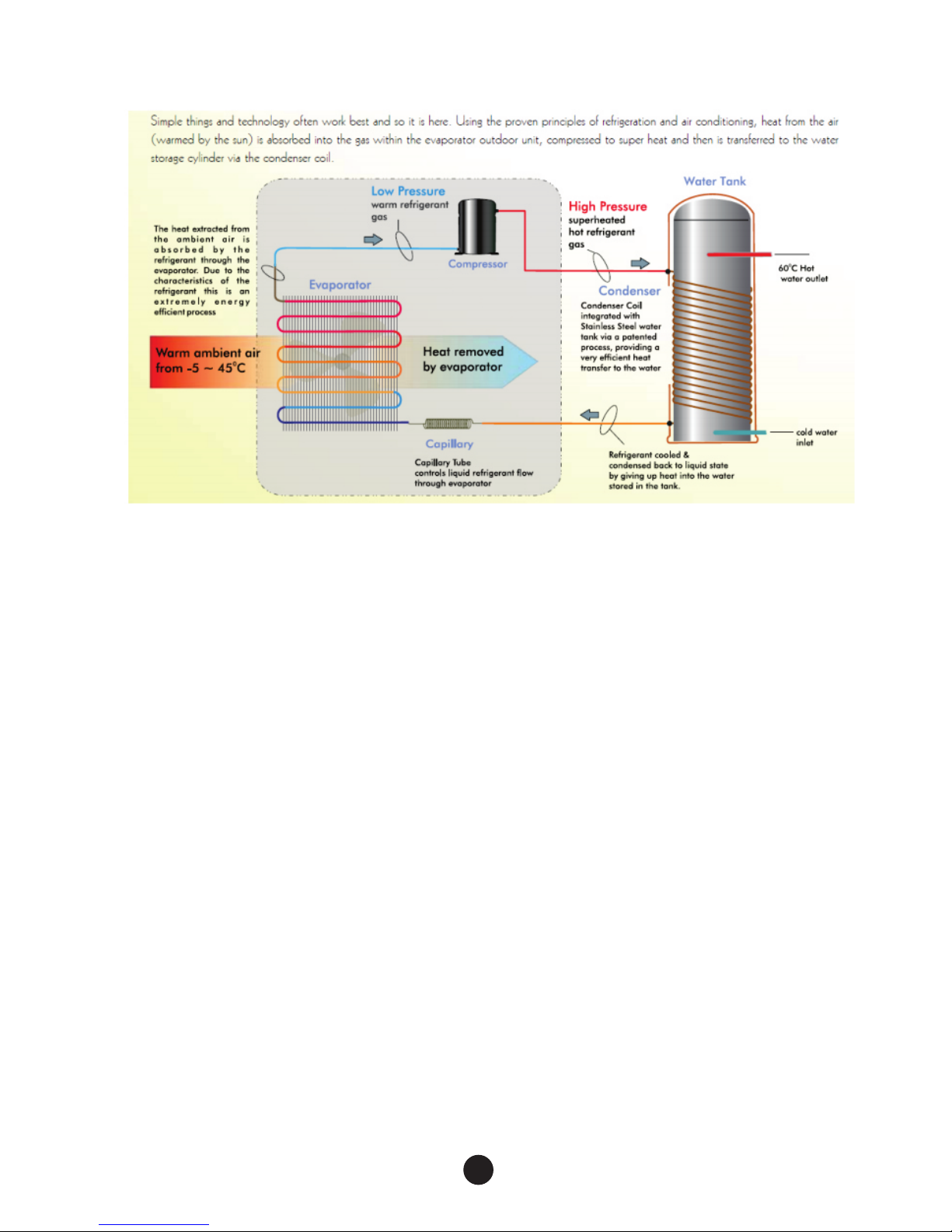
1. How it works ................................................................................
2. Stainless Steel Hot Water Storage Tank.........................................
3. Flexible installation......................................................................
II. Electronic Split Heat Pump..................................................
1. Technical parameters for the main unit ...........................................
2. Electronic Split Heat Pump Dimensions .........................................
3. Heat Pump check .........................................................................
III. Technical Guide..................................................................
1. Starting Current and Peak Current.................................................
2. Electrical wiring...........................................................................
3. Gas Levels and Pressures.............................................................
4. Electronic expansion valve............................................................
IV. Digital Controller................................................................
1. Operation & Adjustment of the Digital Controller..............................
2. Use of Digital Controller....................................................
3. Operation date setting...................................................................
V. System Malfunction Schedule..............................................
VI. Wiring diagram .. .......................................................... ......
RETROFITT ING TO AN EX ISTING SIDDONS C OILED TANK
This new Elec troni c Split heat pump model has i mprov ed features over the prev ious me chanical heat pump.
New feature s inclu de:
* Electroni c tank se nsor probe replacing th e mecha nical Klixon tank therm ostat for regulating th e on/off
function of t he heat p ump
* Electroni c tank se nsor probe replacing th e mecha nical Klixon tank therm ostat f or regulating th e over
temperatu re func tion of the compressor; t his can b e reset by turning p ower to t he heat pump on/off.
* Electroni c tank se nsor probe for activati ng the de -ice function; o n older u nits from 2005, this will r eplac e
the mechani cal Kli xon evaporator thermo stat fo r regulating the de-ice f uncti on
* Pressure sw itche s
* LED display u nit tha t provides diagnostic i nform ation and monitoring of k ey oper ating paramete rs (ref er
Section IV) . Note, t he LED display unit can be pl aced un der the heat pump lid on top of t he elec trical
wiring post o r place d onto a wall using the senso r exten sion lead provided with t he heat p ump)
REFRIGERA NT: This El ectronic Split heat pum p is char ged with 1.5KG of R1 34A refr igera nt, whereas the
older style M echan ical Split heat pump is cha rged wi th 1.5kg of R417a refrige rant.
CONNECTIN G THE NEW H EAT PUMP
* Locate the he at pump a t least 75mm clear of a wall on t he air in let side and at leas t 1m clea r of a wall or
fence on the ai r outle t side.
* Ensure all re frige rant is purged from the exi sting s ystem.
* Connect the e xisti ng refrigeration line s to the ne w refrigeration lines s uppli ed with new electronic he at
pump by brazi ng them t ogether.
* Ensure the ne w heat pu mp and tank and connected w ith no re frigerant leakage.
* Evacuate th e air fro m the refrigerat ion lin es and th e 40m condenser co il wrap ped aro und the tank.
* Fully open bo th refr igeration valves on the h eat pum p to charge the whole syste m.
* Mark the tech nical l abel on the tank, deletin g refer ence to R417a refr igera nt char ge and write in R134 a.
* The digital con troll er can be placed inside the h eat pum p box on top of the term inal bl ock after the heat
pump has been s et, clo ck and timer (if required ) or it can b e fixed onto a wall by using th e exten sion lead
provided. M ake sur e the digital controlle r is prot ected from the weather.
* Fit the drain p lug and c onnect a plastic hose to ta ke the co ndensate water f rom the e vaporator away to a
drain from un derne ath the heat pump. Ang le the he at pump slightly toward s the dra in plug to enable the
condensat e water t o flow easily towards the d rain pl ug. Periodically chec k the dra in plug for any blockages .
* If the heat pum p is moun ted on a wall or on top of a roof, ma ke sure the heat pump’s feet ar e mount ed on
top of rubber p ads to pr event vibration from be ing tra nsmitted.
* It is fine to con nect th e heat pump to off-pea k power b ut keep in mind the heat pump w ill ope rate about
25% more effici ently w ith a 10 degree rise in the amb ient ai r temperature.
* We recommend in stall ing a pool pump timer set bet ween 12 :00pm and 5.00pm i f conne cting to a
continuou s tariff to e nsure one operating cyc le at the w armest time of day f or grea ter efficiency.
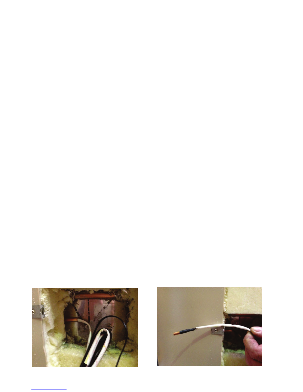
CONNECTIN G THE SEN SOR PROBE TO THE TANK
You will need to fit the t ank water temperature s ensor p robe against the storag e tank wa ll, underneath the
insulatin g foam an d seal with silicone. Her e are the k ey installation point s:
* Make a small ho le with a s crewdriver hard again st the st orage tank 50-75mm long t o fit the p robe tightly
* Push the sens or prob e in right to the end of the hole
* Seal the hole w ith sil icone to ensure the probe g ets a goo d reading from the tank wal l, unaffected by the air
* Secure the se nsor pr obe lead so it cannot fall ou t of posi tion
* Fine tuning a djust ment to the probe cut off/on se ttings can be made if neces sary (r efer Section IV)
I¡General
1
2. Hot Water Storage Tank
1. How it works
3. Flexible installation
The condenser coil for t he Siddons Solarstream mod el MAHRW01 5WAA, with 1.5 hors epower
rotary compressor, is d esigned to operate with a 40m x 3/ 8inch copper condenser coi l wrapped
around a stainless ste el storage tank, insulated o n the casing side with at least 50 mm of foam
insulation and conductive on the water side, or equi valent. Th e coil should either be tightl y
wrapped around the sto rage tank or an equivalent int ernal coil can be used if the inle t water has low
mineral content, typ ically water coming from res ervoir from a mountain catchment, such as exists
in Tasma nia, Melbourne, Canberra a nd Sydney. For other locations, check with your local plumber.
The split system allow s flexible design options an d with the storage tank instal led inside or outside.
It is best for the heat pump t o be installed outside and mad e accessible for any mainten ance. Also
the outlet fan should ha ve at least 1m unimpeded dista nce for the air to blow out.
Installations may va ry from the side by side configu ration of heat pump and water tank to placement
of the heat pump up to 9 metre s distant from the water tank including up to 3 metres above such as
installation of the he at pump on a roof with water tank on t he ground.
The Heat Pump comes pre- charged with 1.5kg of ozone fr iendly R134a refrigerant . This is sufficien t
to charge a side by side sys tem with 2m connection lines a fter it has been connected. For Heat
Pumps installed with e xtension lines, the refrig erant charge should be sligh tly greater than 1.5kg,
allow 30 grams extra per a dditional metre to ensure th e correct refrigeration ch arge in the system.
2
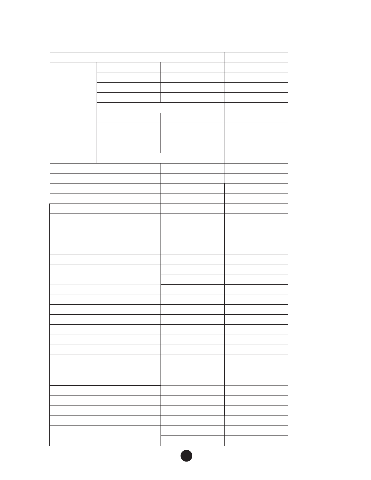
MODEL
COOL ING
HEATING
RATE D CA PACITY
RATE D CU RR ENT
RATE D PO WE R INPUT
EER
STAR R ATING
HEATIN G CA PACI TY
RATE D CU RR ENT
RATE D PO WE R INPUT
EER
STAR R ATING
W
A
W
WW
W
A
W
WW
MAHRW 01 5WA A
3500
4.7
1080
3.15
3500
4.5
1020
3.2
4.5
4
POWER SUP PLY
MAX OPERAT ION CUR RE NT
NOISE LEV EL IN DO OR/OUTD OO R
VOLUMET RI C CAPACI TY
DEHUMID IF ICATIO N CAPACI TY
REFRIGE RA NT TY PE/CHAR GE
Ph/V/Hz
A
dB(A)
3
m / h
L/h
/(g)
1/~220- 24 0/50
10.2
53
620
1.5
R134a /15 00 (g)
INDOOR/ OU TDOOR U NI T
DIMENSI ON ( mm)
NET WEI GH T IND OO R/OUTDO OR
COMPRES SO R TYP E
LCD REMOT E CO NTROL
TEM PE RATURE S ET TING RANG E
OPERATIO N MODES
FAN SPEEDS
24-HOUR O N/ OFF TIM ER
W
D
H
Kg
Liquid
Gas
¡
780
258
540
Kg
10/40
CONNECT IO N PIPE SI ZE m m( inch)
COMPRES SO R TYP E
LCD REMOT E CO NTROL
TEM PE RATURE S ET TING RANG E
OPERATIO N MODES
FAN SPEEDS
24-HOUR O N/ OFF TIM ER
UP/DOWN L OU VER
LEFT/RI GH T LOU VE R
HI-POWE R
SLEEP MOD E
DRY M ODE
LED DISPL AY ON FR ON T PANE L
LIQUID
GAS
6.35(1/ 4)
9.52(3/ 8)
Rotary
Y
O
C
16-30
4
3
Y
Automat ic
Manual
Y
Y
Y
Y
2
M
model
brand
TB36G
Mitsubi sh i
SOFT START
APPLICAT ION AREA *
Compressor
N
18-30
1. Technical parameters for the main unit
II Electronic Split Heat Pump
A
B
C
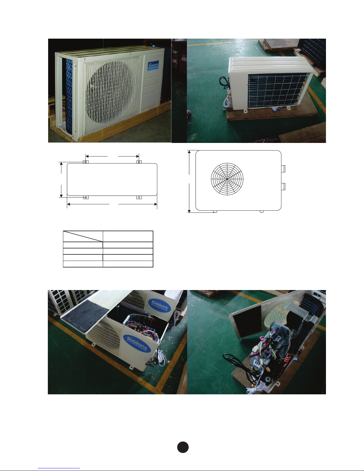
D
Size
Units: mm
MAHRW
280
505
805
542
B
A
C
D
015WA A
2. Electronic Split Heat Pump Dimensions
The heat comes apart easily. Firstly remove the lid, then unscrew the brace on
top of the fan to the front panel, then the screws along the base of the casing
working from the front RHS corner along the base to the left to the back plate
on the opposite corner. Unscrew the two screws connecting the back plate.
3
 Loading...