

Siddons Solarstream MAHRW010ZB, MAHRW010ZB-315VEO, MAHRW010ZP, MAHRW010ZB-250SS, MAHRW010ZB-315SS Owner's Manual
...
Owner s ManualOwner s Manual
AIR TO WATER
HEAT PUMP WATER HEATER
AIR TO WATER
HEAT PUMP WATER HEATER
http://www.siddonssolarstream.comhttp://www.siddonssolarstream.com
CODE:MK4068-02CODE:MK4068-02
SIDDONS SOLARSTREAM Pty LtdSIDDONS SOLARSTREAM Pty Ltd
BOLT-ON split system models:BOLT-ON split system models:
MAHRW010ZB/P
MAHRW010ZB-250SS
MAHRW010ZB-315SS
MAHRW010ZB-250VEO
MAHRW010ZB-315VEO
MAHRW010ZB/P
MAHRW010ZB-250SS
MAHRW010ZB-315SS
MAHRW010ZB-250VEO
MAHRW010ZB-315VEO
without tank
stainless steel tank
stainless steel tank
vitreous enamel tank
vitreous enamel tank
without tank
stainless steel tank
stainless steel tank
vitreous enamel tank
vitreous enamel tank


1
AIR TO WATER HEAT PUMP WATER HEATERAIR TO WATER HEAT PUMP WATER HEATER
ContentsContents
1. One of the World's Most Efficient Ways to Heat Water.......................................
1.2 Dynamic Cycle Flow Heating System.............................................................
1.3 Reduce Greenhouse Emissions...................................................................
1.4 Specifications..............................................................................................
1.5 Schematic...................................................................................................
2. Installation Details...........................................................................................
2.1 General Installation Requirements.............................................................
2.2 Not suitable for Pools and Spas...................................................................
2.3 Heat Pump Positioning................................................................................
2.5 Water Pipe Connections ..............................................................................
2.6 Electrical ................................................................................Connection .
2.7 Storage Tank Positioning............................................................................
2.8 Outdoor Installations..................................................................................
2.9 Indoor Installations.....................................................................................
2.10 Siesmic Restraint......................................................................................
2.11 Filling the Storage Tank.............................................................................
2.12 Legionella.................................................................................................
2.13 Scalding...................................................................................................
2.14 Pressure Limiting Valve............................................................................
2.15 Cold Water Expansion Control Valve.........................................................
2.16 Stop / Isolating Valve................................................................................
2.19 Tempering Valves....................................................................................
2.20 Plumbing Components QIK Kit.................................................................
3. Operating Instructions...................................................................................
3.1 Powering Up...............................................................................................
3.2 Pressure and Temperature Relief Valve Maintenance..................................
3.3 Water Quality..............................................................................................
3.4 Anode.........................................................................................................
3.5 Draining the tank........................................................................................
1.1 Introduction................................................................................................
2.4 Evaporator Drain.........................................................................................
2.17 Pressure and Temperature Relief Valve ....................................................
2.18 Hot Water Connection..............................................................................
2.21 Corrosion Protection ..............................................................................
4
4
4
4
5
6
6
6
6
6
7
7
8
9
9
9
9
9
10
10
10
10
10
10
11
11
11
12
12
12
12
13
13
13

2
ContentsContents
AIR TO WATER HEAT PUMP WATER HEATERAIR TO WATER HEAT PUMP WATER HEATER
6. Maintainance & Service Information................................................................
5. Safety Information...........................................................................................
7. Routine Service..............................................................................................
.
8.3 Operation Data Setting............................................................................................
8.2 Use of remote controller...........................................................................
8.1 Optional Mounting and Fixing of the Remote Controller..........................
8. Operation & Adjustment of the Digital Controller.............................................
8.2a The user interface and function shows as below....................................
8.2c ON/OFF Control....................................................................................
8.2d Electric Heater Control.........................................................................
8.2 Turning On/Off the Ring Main Water Circulating Pump Manually....e ................
8.2f Clock Setting.........................................................................................
8.2g Timer 1 ON/OFF Setting..........................................................................
8.2h Setting of Timer 2, Ring Main Water Supply Flow and Return Line...................
8.2i Cancellation of Timing Setting Operation ...............................................
8.2j Parameter Setting ..................................................................................
9. Recognition of Abnormal Operation...............................................................
9.1 Pressure & Temperature Relief Valve Running...........................................
9.1a Continuous Trickle................................................................................
9.1b Steady Flow...........................................................................................
9.2 No Hot Water............................................................................................
8.2b Initial Power On and Standby Status.....................................................
4. Storage Tank Specifications...........................................................................
4.2 Glass Lined / Vitreous Enamel Storage Tank Models...................................
4.1 Stainless Steel Storage Tank Models..........................................................
5.1 Safety Devices...........................................................................................
5.2 ....................................................... Water Heater Unused for Long Periods
6.1 No Puncturing the Water Tank ...................................................................
6.2 Cleaning the Evaporator Coils...................................................................
6.3 Sacrificial Anode.......................................................................................
6.4 Capacitors.................................................................................................
7.1 Access and removal of Sacrifical Anode....................................................
7.2 Flushing of Water Tank..............................................................................
7.3 Thermal Overload (Incorporated in Digital Controller) ..............................
14
14
14
14
14
15
15
15
15
15
15
16
16
16
16
16
17
17
17
18
18
18
19
19
19
19
20
20
21
22
22
22
22
22

ContentsContents
AIR TO WATER HEAT PUMP WATER HEATERAIR TO WATER HEAT PUMP WATER HEATER
3
10. System Malfunction Schedule............................................................................
11. Judgement and Solution of Malfunctions........................................................
12. Wiring Diagram..............................................................................................
13. Warranty Policy (Australia Only)....................................................................
23
24
25
26
26
26
27
27
28
28
28
13.1 Warranty Terms.........................................................................................
13.2 Warranty Conditions.................................................................................
13.3 Exclusions................................................................................................
13.4 Water Quality Limits - Warranty Exclusion.................................................
13.5 How to make a Warranty Claim...................................................................
13.6 Tanamet Crystal Water Filters...................................................................
13.7 Australian Consumer Law.........................................................................

4
1. One of the World's Most Efficient Ways to Heat Water
Congratulations on purchasing a SIDDONS Solarstream energy efficient Heat Pump Water
Heater, designed for Australian conditions to produce many years of low energy hot water.
This water heater typically uses up to 75% less energy than a conventional electric element
water heater by absorbing heat from the surrounding air of between -5 and 45 degrees C,
night and day. It works in hail, rain and shine and becomes more efficient as the air
temperature and humidity rise. You can expect around 20% greater efficiency per 10 degree
rise in the ambient air temperature.
SIDDONS, with its partners, designs and manufactures energy efficient Heat Pump Water
Heaters for global markets using the best quality components sourced from Australia,
Germany, Japan and China.
Heat Pump Water Heaters can be used for factories, schools, hotels, motels, restaurants,
hospitals, beauty salons, spas, laundries, etc.
1.2 Dynamic Cycle Flow Heating System
The Dynamic Cycle flow heating system is used to convert an average of 1 kW/h of input
electrical energy into 3.5 kW/h of heat energy, more or less, depending on ambient air
temperature and humidity. Cold water from the bottom of the storage tank is cycled through
the heat exchanger in the Heat Pump outdoor unit then back to the storage tank until all the
water is completely heated.
As the name implies, an air to water Heat Pump Water Heater is a machine that pumps or
transfers heat absorbed from the ambient air into the water. Even at - 5 deg C, there is
enough heat in the air to boil the liquid refrigerant into a gas. Once in the form of a gas, it
can be compressed to superheat up to 95 deg C; this heat is then pumped into the water
through a double layered, tube inside tube heat exchanger. One tube takes the hot
compressed gas whilst the other takes the cold water from the tank. The advantages of
this method are:
1.3 Reduce Greenhouse Emissions
With a SIDDONS Solarstream, you are greatly assisting the reduction of global greenhouse
gas emissions if you can replace bottled gas, wood fired or a conventional electric element
water heater, the latter typically consumes 1/4 to 1/3 of a household's power usage. If you want
your water heater to be completely carbon neutral, then also install a small electricity
generating system such as a Photo Voltaic solar panel or wind power.
· Excellent heating efficiency
· Stable hot water without over heating at the top or under heating at the bottom
· All of the tank water is heated
1.1 Introduction
AIR TO WATER HEAT PUMP WATER HEATERAIR TO WATER HEAT PUMP WATER HEATER

5
1.4 Specifications
Model Number
Rated Heating Capacity (1)
Rated Input Power (1)
Rated Input Current (1)
Rated COP (1)
Rated Heating Capacity (2)
Rated Input Power (2)
Rated Input Current (2)
Rated COP (2)
Hot Water Recovery Rate (average)
Maximum input current
Power Supply
Maximum water inlet temperature
Maximum water outlet temperature
Noise
Compressor type
Water Outlet/Water Inlet
Water Flow Volume
Refrigerant type
Heat Pump Dimensions (L/M/H)
Shipping Dimensions (L/M/H)
Heat Pump Weight
Shipping Weight
MAHRW010ZB/P
kW
kW
A
W/W
kW
kW
A
W/W
L/h
A
V/PH/Hz
deg C
deg C
dB(A)
Inch
m /h
mm
mm
kg
kg
3.5
0.97
4.4
3.6
2.8
0.84
3.8
3.3
75
6.6
220/1/50
55
60
48
Rotary
3/4
0.6
R134A
590/540/690
640/590/725
55
60
Notes:
Scenario (1): Outdoor air temp Dry Bulb 20 / Wet Bulb 15 deg C
Scenario (2): Outdoor air temp Dry Bulb 7 / Wet Bulb 6 deg C
Water tank temp rise 40 deg C
Model Nomenclature
MA HR W S - *** - W A B / P S (B D)
Source medium
MA: Air source
MW: Ground source
Function of the unit
HR: Heating
Energy exchange medium
A: Refrigerant
W: Water
Z: Integrated type
W: Split type(indoor unit )
A: Coil heating
B: Circulating heating
A: Horizontal fan direction
B: Upward fan direction
C: Double air duct type
The figure represents the horse power of unit
eg: 010 means 1 horse power
P: With built in pump
(without built in pump omitted)
S: 3phase (single phase omitted)
S: With solar
(Without solar omitted)
D: With electrical heating
(Without electrical heating omitted)
B: Inverter
E: EVI
(Without inverter or EVI omitted)
3
AIR TO WATER HEAT PUMP WATER HEATERAIR TO WATER HEAT PUMP WATER HEATER
6
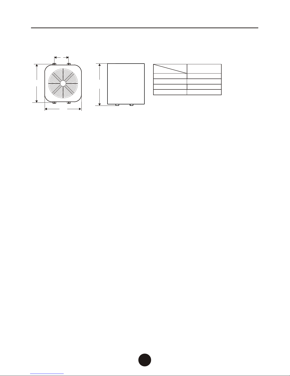
1.5 Schematic
Appearance and Mounting Dimensions
B
A
C
A
B
C
D
Size
Units: mm
MAHRW
566
180
540
690
010ZB/(P)
D
2.2 Not suitable for Pools and Spas
Note, this heat pump is not suitable for pool or spa heating due to the high levels of salt
and/or chlorine used and volume of water to be heated. If used for such applications,
your warranty will be void.
2.3 Heat Pump Positioning
The heat pump extracts heat from the air being drawn through the fin coils of the
evaporator. This produces cold outlet air as a by-product. In order for the heat pump to
operate efficiently, good ventilation is required to extract the heat from the air easily and
therefore the heat pump is best located outside.
The R134a refrigerant used has a boiling point of minus 26 deg C so there is no risk of
damage to the heat pump from frost. Performance may be reduced in very low
temperatures but the system will not be damaged by such climatic conditions.
The cold exhaust air should not be allowed to feed back into the inlet or operational efficiency
will be reduced. The heat pump should not facing into a prevailing wind. However, alternate
locations may be used such as a large double garage (minimum of 120 cubic metres).
Note: For water pipe connection instructions, refer section 2.5 below.
2.1 General Installation Requirements
This water heater must be installed by a licensed trades person in accordance with:
1). AS 3500.4, National Plumbing And Drainage Code, Part 4: Hot Water Supply Systems
2). AS 3500.4.2, National Plumbing And Drainage Code, Part 4.2: Hot Water Supply Systems
Acceptable Solutions
3). Other relevant Australian Standards, Industry or Local Water Supply regulations or codes
for mains pressure storage tanks
Note: This water heater is not suitable for pool heating or building heating.
2. Installation Details
AIR TO WATER HEAT PUMP WATER HEATERAIR TO WATER HEAT PUMP WATER HEATER
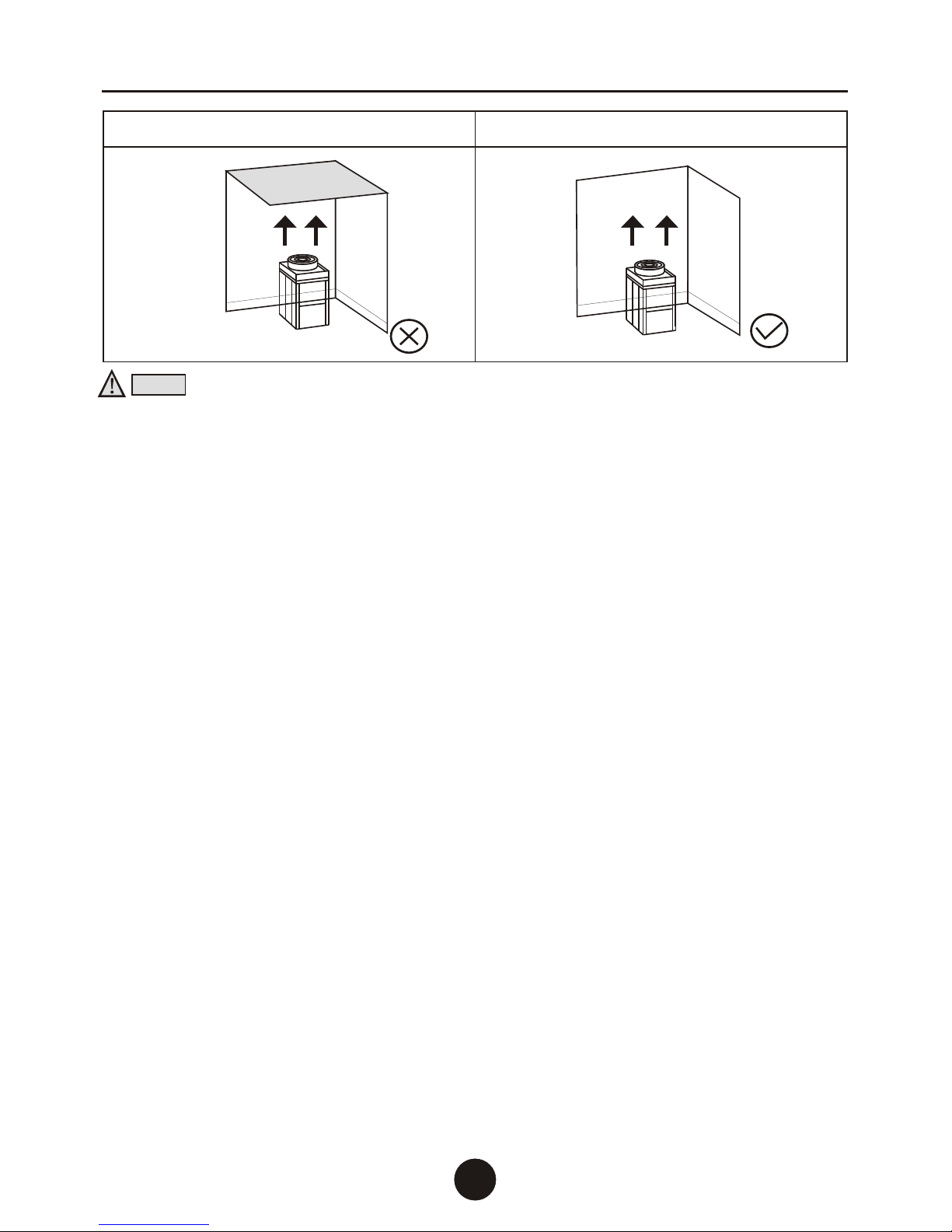
Notice:
Wrong Right
1) Keep enough space around the unit for maintenance access with at least 200mm of
clear space for evaporator coils so there is good air flow into the evaporator.
2) Ensure the heat pump is sited onto a flat, level surface. Use a 600mm x 600mm concrete
slab if the installation base is not solid.
3) Install the metal feet of the heat pump onto the rubber feet supplied and bolt it onto the
base.
4) It is a good idea to install the heat pump with some weather protection such as an eave
to protect against direct sunlight which may make the fan blade brittle over time.
5) Protect the heat pump from salt spray if near the coast as this will reduce its operating life.
6) Ensure there is space above the heat pump for the outlet air to blow upwards unimpeded.
7) The heat pump and storage tank may be installed on a balcony, roof, floor or other
convenient place but you must ensure your site has load-bearing to cope with the weight
as specified plus the weight of the water inside the storage tank (1kg per litre).
8) During operation, condensate water will flow from the evaporator so use a length of hose
connected to the drain hole elbow to take the condensate water to a drain.
9) If your only option is to locate the heat pump inside a large internal space such as a
garage, this space should be well ventilated or the heat pump will turn it into a cool room
and your heating efficiency will decrease (keep in mind that a 10 degree C reduction in
air temperature will cause approximately 20% lower efficiency).
7
2.4 Evaporator Drain
During operation, considerable amounts of condensate water will flow from the evaporator
drain. If allowed to simply flow out of the outlet, this water may pool below the unit and can
cause problems to both the water heater and area around it. The evaporator drain should
be properly drained using a length of hose or pipe in accordance with regulations but must
not be connected directly to the PTR valve or expansion valve drain.
AIR TO WATER HEAT PUMP WATER HEATERAIR TO WATER HEAT PUMP WATER HEATER
2.5 Water Pipe Connections
1) Water pipe connections should be heat-resistant, rust-proof, resist fouling and conform
to national health and safety standards. The water pipe can be stainless steel pipe,
copper pipe, aluminium water pipe, hot water PPR pipes, etc.
2) Ensure all water pipes are clean and rust free to prevent pipe blockage.
3) The water circulating pipes from the heat pump should be installed with the least amount
of bending and distance from the water storage tank for optimum efficiency. We recommend
between 2m to 5m as an ideal distance for the water circulating pipes.

4) The water outlet of the heat pump should connect to the of the
storage tank.
5) Ensure that all the pipes are tightly connected and test for leaks.
6) Apply insulation onto the pipes and plumbing fittings to minimise heat loss.
hot water outlet port
AIR TO WATER HEAT PUMP WATER HEATERAIR TO WATER HEAT PUMP WATER HEATER
Water Circulating Pipe Connection Instructions:
Cold water
Hot water
Cold water
Hot water
Option B: Single set of water inlet/outlet ports
plus ring main return port
Use a Tee Piece and one-way valve on inlet
cold water pipe from the water storage tank to
add the water circulating inlet pipe to the heat
pump with return water flowing back to the middle
ring main port on the water storage tank.
Cold water
Hot water
2.6 Electrical
SIDDONS water heaters are designed for single-phase 220/240V A/C supply only. A certified
electrician must carry out all electrical work in accordance with regulations including AS3000.
A 15-amp circuit breaker should be installed at the power supply for the hot water unit.
A separate circuit breaker is recommended for each unit in the case of multiple installations.
The connection will require an approved, standard 240V 15A On / Off switch or
Junction Box in close proximity to the heater.
Key points:
1) The heat pump should ideally be supplied with a dedicated 240 Volt 15 Amp power supply
2) The heat pump should ideally be connected using a 15 Amp power cable
3) The heat pump power supply circuit must have a grounding wire
4) Power lines and signal lines should be neat and rational, with strong and weak lines
separated so they cannot interfere with each other; leave appropriate distance between
the lines
5) Electrical maintenance must be done by qualified technicians (refer to circuit diagram
below)
6) Unit control panel Code MK4068
7) Fuse specifications: 5A/250V
) The appliance must be installed in accordance with regulations
Connection
isolating
8
8
Option A: Single set of water inlet/outlet ports
Use a Tee Piece and one-way valve on both pipes
to add the water circulating pipe connections
between the heat pump and water storage tank.
Option C: Double set of water inlet/outlet ports
plus ring main return port
Connect the heat pump water circulating inlet
pipe to the spare cold water inlet port on the water
storage tank with return water flowing back to the
middle ring main port.
 Loading...