


User’s manual PE22A
1
USER’S MANUAL
PE 22 A
BENCH DRILLING MACHINE
Original manual

User’s manual PE22A
2
CONTENTS
1.
1.1.
1. INTRODUCTION
INTRODUCTIONINTRODUCTION
INTRODUCTION ................................
................................................................
................................................................
................................................................
................................................................
................................................................
................................................................
................................................................
................................................................
................................................................
................................................................
................................................................
..........................................
....................
..........3333
2.
2.2.
2. WARNING SIGNS
WARNING SIGNSWARNING SIGNS
WARNING SIGNS ................................
................................................................
................................................................
................................................................
................................................................
................................................................
................................................................
................................................................
................................................................
................................................................
................................................................
................................................................
.......................................
..............
....... 3333
2.1. WARNING SIGNS RELATED TO THE SAFETY OF THE MACHINE ............................................................................................................. 3
2.2. WARNING SIGNS USED IN THIS MANUAL....................................................................................................................................................... 3
3.
3.3.
3. SAFETY
SAFETYSAFETY
SAFETY................................
................................................................
................................................................
................................................................
................................................................
................................................................
................................................................
................................................................
................................................................
................................................................
................................................................
................................................................
..........................................................
....................................................
..........................4444
3.1. GENERAL SAFETY INSTRUCTIONS.......................................................................................................................................................................4
3.2. PARTICULAR SAFETY INSTRUCTION ..................................................................................................................................................................5
3.3. PROTECTION OF THE OPERATOR ......................................................................................................................................................................... 6
4.
4.4.
4. DESCRIPTION AND OPER
DESCRIPTION AND OPERDESCRIPTION AND OPER
DESCRIPTION AND OPERATING
ATINGATING
ATING................................
................................................................
................................................................
................................................................
................................................................
................................................................
................................................................
................................................................
................................................................
................................................................
............................................
........................
............ 6666
4.1. PURPOSE OF THE MACHINE .................................................................................................................................................................................. 6
4.2. SPECIFICATIONS .......................................................................................................................................................................................................... 6
4.3. MACHINE OVERVIEW ................................................................................................................................................................................................ 7
5.
5.5.
5. INSTALLATION
INSTALLATIONINSTALLATION
INSTALLATION ................................
................................................................
................................................................
................................................................
................................................................
................................................................
................................................................
................................................................
................................................................
................................................................
................................................................
................................................................
............................................
........................
............ 8888
5.1.
PACKING..................................................................................................................................................................................................... 8
5.2.
TRANSPORT AND HANDLING ...........................................................................................................................................................8
5.3.
INSTALLING THE MACHINE................................................................................................................................................................. 8
5.4.
ASSEMBLING ............................................................................................................................................................................................ 9
5.5.
ELECTRICAL CONNECTION............................................................................................................................................................... 12
5.6.
TEST AND INITIAL INSPECTION PRIOR TO USING THE EQUIPMENT FOR THE FIRST TIME................................... 12
6.
6.6.
6. OPERATING THE BENCH
OPERATING THE BENCH OPERATING THE BENCH
OPERATING THE BENCH DRILLING MACHINE
DRILLING MACHINEDRILLING MACHINE
DRILLING MACHINE................................
................................................................
................................................................
................................................................
................................................................
................................................................
................................................................
................................................................
...............................................
..............................
............... 13
1313
13
6.1.
CONTROL PANEL.................................................................................................................................................................................. 13
6.2.
RETURN SPRING OF THE SPINDLE............................................................................................................................................... 13
6.3.
DRILLING DEPTH .................................................................................................................................................................................. 13
6.4.
PROTECTIVE SHIELD ........................................................................................................................................................................... 14
6.5.
TABLE........................................................................................................................................................................................................ 15
6.6.
ASSEMBLING AND DISMANTLING THE TOOL.......................................................................................................................... 16
6.7.
SELECTING ROTATING SPEEDS OF THE SPINDLE................................................................................................................... 17
6.8.
LASER DEVICE........................................................................................................................................................................................ 19
6.9.
DIGITAL DISPLAY.................................................................................................................................................................................. 19
6.10.
DRILLING PROCEDURE ...................................................................................................................................................................... 20
6.11.
STORING THE MACHINE WHEN IT IS NOT USED.................................................................................................................... 20
6.12.
TROUBLESHOOTING............................................................................................................................................................................ 21
7.
7.7.
7. MAINTENANCE
MAINTENANCEMAINTENANCE
MAINTENANCE................................
................................................................
................................................................
................................................................
................................................................
................................................................
................................................................
................................................................
................................................................
................................................................
................................................................
................................................................
........................................
................
........ 23
2323
23
7.1.
DAILY MAINTENANCE ........................................................................................................................................................................ 23
7.2.
WEEKLY MAINTENANCE .................................................................................................................................................................. 23
7.3.
MONTHLY MAINTENANCE...............................................................................................................................................................23
7.4.
6-MONTH MAINTENANCE................................................................................................................................................................ 23
8.
8.8.
8. EXPLODED VIEW
EXPLODED VIEWEXPLODED VIEW
EXPLODED VIEW ................................
................................................................
................................................................
................................................................
................................................................
................................................................
................................................................
................................................................
................................................................
................................................................
................................................................
................................................................
.....................................
..........
..... 24
2424
24
9.
9.9.
9. ELECTRICAL CIRCUIT
ELECTRICAL CIRCUITELECTRICAL CIRCUIT
ELECTRICAL CIRCUIT ................................
................................................................
................................................................
................................................................
................................................................
................................................................
................................................................
................................................................
................................................................
................................................................
.............................................................
..........................................................
............................. 26
2626
26
10.
10.10.
10. NOISE LEVEL
NOISE LEVELNOISE LEVEL
NOISE LEVEL ................................
................................................................
................................................................
................................................................
................................................................
................................................................
................................................................
................................................................
................................................................
................................................................
................................................................
................................................................
.............................................
..........................
............. 27
2727
27
11.
11.11.
11. VIBRATIONS LEVEL
VIBRATIONS LEVELVIBRATIONS LEVEL
VIBRATIONS LEVEL................................
................................................................
................................................................
................................................................
................................................................
................................................................
................................................................
................................................................
................................................................
................................................................
................................................................
................................................................
.................................... 27
2727
27
12.
12.12.
12. PROTECTION OF THE EN
PROTECTION OF THE ENPROTECTION OF THE EN
PROTECTION OF THE ENVIRONMENT
VIRONMENTVIRONMENT
VIRONMENT ................................
................................................................
................................................................
................................................................
................................................................
................................................................
................................................................
................................................................
..............................................................
............................................................
.............................. 27
2727
27
13.
13.13.
13. GUARANTEE
GUARANTEEGUARANTEE
GUARANTEE ................................
................................................................
................................................................
................................................................
................................................................
................................................................
................................................................
................................................................
................................................................
................................................................
................................................................
................................................................
.............................................
..........................
............. 27
2727
27
14.
14.14.
14. DECLARATION OF CONFO
DECLARATION OF CONFODECLARATION OF CONFO
DECLARATION OF CONFORMITY
RMITYRMITY
RMITY ................................
................................................................
................................................................
................................................................
................................................................
................................................................
................................................................
................................................................
................................................................
................................................................
.......................................
..............
....... 28
2828
28

User’s manual PE22A
3
1.
1.1.
1. INTRODUCTION
INTRODUCTIONINTRODUCTION
INTRODUCTION
For safety reasons, please careful
For safety reasons, please carefulFor safety reasons, please careful
For safety reasons, please carefully read these instructions, prior to using this machine.
ly read these instructions, prior to using this machine.ly read these instructions, prior to using this machine.
ly read these instructions, prior to using this machine.
Serious injuries to persons or damages to the machine may be caused by the non
Serious injuries to persons or damages to the machine may be caused by the nonSerious injuries to persons or damages to the machine may be caused by the non
Serious injuries to persons or damages to the machine may be caused by the non----observance of these instructions
observance of these instructionsobservance of these instructions
observance of these instructions....
This manual is intended to be used by operators, setters
and service engineers.
This manual is an important part of your equipment. It
provides rules and guidance to help you safely operating this
machine. You must read this manual and make sure of the
correct procedures and functions before operating the
machine. For your own safety, you must read these
precautions carefully and follow the instructions described
below.
These instructions must be followed anytime when
operating and servicing the machine. Serious injury and/or
failure of the machine may occur if operators fail in
observing safety guidance and instructions and operate the
machine in a wrong and different way from the one
described in this manual.
Please keep the manual with the machine or in a safe place
to make it available anytime. Make sure any person involved
in operating this machine can consult this manual. In case
this manual is damaged or lost, please contact us or your
dealer to be provided with a new manual.
Always use genuine SIDAMO parts and components.
Replacing SIDAMO parts and components by improper
parts may damage the machine and cause serious injuries
to operators.
This manual describes the safety instructions to be applied
by the operator. Both the employer and operators are
responsible, according to the article L.4122-1 of Labour
Laws, to take care of their health and safety and of the
health and safety of any other person involved by any action
or omission related to instructions given to them.
The employer is in charge of performing the assessment of
all particular risks related to the activity of his/her company.
He/she must train workers to operating the machine and
to the prevention of risks and provide with appropriate
information and instructions all workers in charge of
operating or servicing working equipments.
2.
2.2.
2. WARNING SIGNS
WARNING SIGNSWARNING SIGNS
WARNING SIGNS
2.1.
2.1.2.1.
2.1. WARNING SIGNS REL
WARNING SIGNS RELWARNING SIGNS REL
WARNING SIGNS RELATED TO THE SAFETY O
ATED TO THE SAFETY OATED TO THE SAFETY O
ATED TO THE SAFETY OF THE MACHINE
F THE MACHINEF THE MACHINE
F THE MACHINE
Meaning of the safety signs attached to the machine (They must remain clean. Replace them immediately in case they are peeled
off or illegible) :
Always wear protective goggles
Always wear ear protection
Carefully read the User’s Manual
Always wear protective shoes
Do not wear loose clothes, loose sleeves, jewels,
bracelets, watches, rings, …
Wear a hair covering to protect long hair
Wear protective gloves
We do not recommend wearing gloves when
machining. But we recommend wearing gloves
when cleaning, the machine being stopped, and
for any operation presenting any risk of cut, burn,
pinching …
Rotation direction of the spindle
2.2.
2.2.2.2.
2.2. WARNING SIGNS USED I
WARNING SIGNS USED IWARNING SIGNS USED I
WARNING SIGNS USED IN THIS MANUAL
N THIS MANUALN THIS MANUAL
N THIS MANUAL
Straight hazard for human persons and the
machine
The machine and its vicinity may be damaged
Technical ability level : operator, user
Minimal number of persons required to perform
some operations
Technical ability level : setter, service
Technical ability level : maintenance agent
Note
Only low voltage qualified and authorized workers should be allowed to perform interventions on the electrical
Only low voltage qualified and authorized workers should be allowed to perform interventions on the electrical Only low voltage qualified and authorized workers should be allowed to perform interventions on the electrical
Only low voltage qualified and authorized workers should be allowed to perform interventions on the electrical
circuit.
circuit.circuit.
circuit.
User’s manual PE22A
4
3.
3.3.
3. SAFETY
SAFETYSAFETY
SAFETY
3.1.
3.1.3.1.
3.1. GENERAL SAFETY INSTR
GENERAL SAFETY INSTRGENERAL SAFETY INSTR
GENERAL SAFETY INSTRUCTIONS
UCTIONSUCTIONS
UCTIONS
Always follow the basic safety instructions to reduce risks of fire, el
Always follow the basic safety instructions to reduce risks of fire, elAlways follow the basic safety instructions to reduce risks of fire, el
Always follow the basic safety instructions to reduce risks of fire, electric shock, mechanical crash and injury for any
ectric shock, mechanical crash and injury for any ectric shock, mechanical crash and injury for any
ectric shock, mechanical crash and injury for any
person using power tools
person using power toolsperson using power tools
person using power tools....
This manual considers only reasonably predictable
behaviours.
Our machines are designed keeping first in mind the safety
of operators.
We accept no responsibility for any damage cause by the
lack of experience, any improper use of the machine and/or
the machine being damaged and/or instructions provided
by this manual not being followed.
Accidents always happen following an improper use or
because the User’s Manual was not read and understood.
We remind you that in case changes are performed on the
machine, we will be freed from our obligations.
Before starting operating the machine, always check that
guards are in place and in working condition.
Make sure moving parts run correctly, that no element is
damaged and that the machine runs correctly when it is
commissioned.
Only authorized and qualified workers should be allowed to
repair or replace faulty parts.
Keep the vicinity of the machine tidy. Put everything in order.
Make sure the operator can see the entire working area
from the working station.
Untidy working areas and benches are hazardous and can
cause serious injuries.
Never use the machine outdoor ; never expose it to rain and
damp, or to an atmosphere containing flammable fluids.
Provide good lighting conditions to the machine.
No worker under the age of eighteen is allowed to operate
the machine.
Keep children, animals and unauthorized persons away from
the working area. They are not allowed to touch either tools
or electric cables.
Never leave a running machine unattended. Always switch
the machine off. Never leave the machine until it comes to a
full stop.
Never force a tool. It will do the job better and be
safer if it used at the rate it was designed for.
Do not force small tools to perform a machining that should
be done by a larger tool.
Use the right tool and do not use tools for a job they were
not designed for.
Never damage electric cables.
Never pull the power cable to unplug the machine.
Keep the main power cable away from heat sources, greasy
parts and/or sharp edges.
Never use the power cable in wet conditions and protect it
from any damage.
Regularly check the condition of the power cable. In case it
is damaged, have it repaired by an authorized repairer. Only
an authorized company should replace faulty switches.
Never try to run the machine in case the main switch is out
of work.
Do not overestimate your strength.
Do not overreach. Never lose balance.
Always be aware. Use common sense and do not run the
machine when you are tired.
Always use both hands to run the machine.
Use only recommended accessories. Using accessories
different from the ones recommended in this manual may
be hazardous.
The user is responsible for the machine and must make
sure that :
Only qualified, authorized and trained workers can
use the drilling machine.
Safety instructions are followed.
Users have read and understood the safety
instructions.
Users have read and understood the User’s
Manual.
Responsibilities for servicing and possibly repairing
have been correctly assigned and followed.
Failures and faults have immediately been
communicated to an authorized repairer or to your
dealer.
The drilling machine is used for applications
described in this manual.
Do not use the machine for any application other
than that it was designed for. Any other use is
hazardous.
Never remove or bypass mechanical and/or
electrical protections.
Never try to modify or retrofit the machine.
SIDAMO accepts no responsibility for any damage caused to
persons, animals or objects, and resulting from the nonobservance of the safety instructions described in this
manual.

User’s manual PE22A
5
3.2.
3.2.3.2.
3.2. PARTICULAR SAFETY IN
PARTICULAR SAFETY INPARTICULAR SAFETY IN
PARTICULAR SAFETY INSTRUCTION
STRUCTIONSTRUCTION
STRUCTION
Particular safety instructions related to bench drilling machines.
Particular safety instructions related to bench drilling machines.Particular safety instructions related to bench drilling machines.
Particular safety instructions related to bench drilling machines.
Prior to using this machine, check it has been correctly
assembled.
Do not connect to power if the drilling machine has not been
installed on a flat and stable place, showing no obstacles
and where lighting conditions are correct.
Do not use the machine if the protective guard of the belts
is not fitted.
Adjust the protective shield to prevent any access to the
non-working part of the tool.
Do not use any damaged or warped drill.
Make sure you have selected the right drill and the right
rotating speed, in relation with the material to drill.
Check whether the tension of belts is correct.
Use only adapted drilling rotating speeds. Always select a
speed when the machine has stopped.
Make sure the drill is firmly clamped into the chuck.
Do not touch the drill when it is rotating.
Always wear protective goggles.
In any case, always be concentrated on the work.
We do not recommend wearing gloves when machining.
We do not recommend wearing gloves when machining. We do not recommend wearing gloves when machining.
We do not recommend wearing gloves when machining.
Wear gloves when cleaning.
Always stop the machine and wear protective gloves when
performing hazardous tasks, presenting risks of burn, cut,
pinching, entanglement, winding, crushing, especially when
loading and unloading the tool, when handling the table, the
vice, the clamps, the workpiece.
Do not rush as it is very often a waste of time : the tool
heats, it becomes blunted and it requires grinding. The work
is not well done. There are more risks of accidents.
Always wear an ear protection.
Never hold the workpiece by hand. Always clamp the
workpiece using adapted work-holding devices, such as vices
and clamps.
Thin metal sheets are the most hazardous work pieces :
- They can cut, as they are very thin.
- The drill tends to plunge once it goes through the metal
sheet.
- Offset holes increase hazards as the workpiece, when
rotating, moves along a circle. Fingers, wrists, forearms
and event the chest are particularly exposed.
Use fixtures and clamps :
- Support fixture for flexible work pieces and work pieces
with steps.
- Guiding bush to drill small holes in a thin sleeve.
To not drill the table, adjust the table or the drilling depth.
The working table must remain clean and not populated.
Wear a breathing apparatus to reduce the risk of breathing
harmful dusts.
Prevent coolant from overflowing all around the machine, as
it is a very slippery product.
Prior to changing the workpiece or performing any
positioning or any removal of material wastes, always stop
the machine by using the Emergency Stop Slam button with
lock.
To use this Emergency Stop Slam button with lock, simply
close the cover of the control box, but do not lock it.
Prior to performing any important operation (maintenance,
servicing, …) always unplug the machine from the main
power.
Do not install additional equipments to perform tasks they
were not designed for.
Using improper tools is hazardous.
Make sure the guard of the fan is clean. Do not cover it.
Otherwise the machine could not be correctly operated.
The drill must remain perfectly clean.
Do not clean the drill when it is rotating.
The drill can become very hot during the machining. Before
replacing the drill, wait until it is cold.
When cleaning, first stop the machine and wear protective
goggles and gloves to remove chips. Collect them into tanks.
Do not use an air gun. Prefer using a vacuum cleaner, a
brush, a painting brush with long handle or a hook.
Never wash the machine using water under pressure as
water can get into electric parts.
Never use solvent or aggressive detergents.
When moving the machine, stop it and make sure all moving
parts are safely fixed.
Store the machine in a cool place, out of the reach of
children.
Accidents usually happen because :
There are no accessories used to properly hold the
workpiece.
Disorder : accessories, if present, are not set in
order, and the operator do not use them, as he
cannot find them.
Hazardous or inappropriate operating mode.
Insufficient training, learning and/or experience of
operators to use the machine.
Lack of protective guards during the operating of
the machine.
Loose cloths, no protective goggles when
performing some tasks.

User’s manual PE22A
6
3.3.
3.3.3.3.
3.3. PROTECTION OF THE OP
PROTECTION OF THE OPPROTECTION OF THE OP
PROTECTION OF THE OPERATOR
ERATORERATOR
ERATOR
TTTTo ensure operator’s safety, make sure that non
o ensure operator’s safety, make sure that nono ensure operator’s safety, make sure that non
o ensure operator’s safety, make sure that non----working parts are protected by a guard.
working parts are protected by a guard.working parts are protected by a guard.
working parts are protected by a guard.
This machine was designed to be operated by only one
operator.
The operator should wear adapted Personal Protective
Equipments, such as :
Protective goggles.
Ear protections.
Safety shoes.
Protective gloves.
The operator should wear tight clothes and should wear a
hair covering to protect long hair, if necessary.
For example, the operator should never wear :
Loose clothes or sleeves.
Bracelets, watch, ring, jewels.
Any other object subjected to be caught or
entangled by moving parts of the machine.
4.
4.4.
4. DESCRIPTION AND OPER
DESCRIPTION AND OPERDESCRIPTION AND OPER
DESCRIPTION AND OPERATING
ATINGATING
ATING
4.1.
4.1.4.1.
4.1. PURPOSE OF THE MACHI
PURPOSE OF THE MACHIPURPOSE OF THE MACHI
PURPOSE OF THE MACHINE
NENE
NE
The bench drilling machine PE22A is designed and
manufactured only to perform drilling, on a fixed station,
using a vertical stroke, on steel, ferrous and non-ferrous,
plastic and wooden work pieces.
When operating and maintenance are correct, the drilling
machine can provide many years of safe and consistent
work.
To do so, please thoroughly examine the different functions
of the machine.
4.2.
4.2.4.2.
4.2. SPECIFICATIONS
SPECIFICATIONSSPECIFICATIONS
SPECIFICATIONS
Digital display of the drilling depth
Protective shield of the servo chuck
Drilling position laser device
LED lighting
Belt guard fitted with a safety grip micro switch
« ON/OFF» switch fitted with an under voltage coil
Emergency Stop Slam button with lock
Transmission using dented belts pulleys
Spindle fitted with ball bearings
Ferro steel column
Square table tilting up to 45°, fitted with a coolant
collector
Rack-drive table
Comes standard with a self-clamping chuck, a
chuck shank, a taper drift, a screw vice and a set of
clamps
Max. drilling
Max. drilling Max. drilling
Max. drilling
capacity
capacitycapacity
capacity
(mm)
(mm)(mm)
(mm)
Morse
Morse Morse
Morse
taper
tapertaper
taper
Column
ColumnColumn
Column
ØØØØ
(mm)
(mm) (mm)
(mm)
Spindle
Spindle Spindle
Spindle
stroke
strokestroke
stroke
(mm)
(mm)(mm)
(mm)
Number
Number Number
Number
of gears
of gearsof gears
of gears
Spindle speed
Spindle speed Spindle speed
Spindle speed
range
rangerange
range
(rpm)
(rpm)(rpm)
(rpm)
Dimensions
DimensionsDimensions
Dimensions
(L x H x D)
(L x H x D)(L x H x D)
(L x H x D)
(mm)
(mm)(mm)
(mm)
Motor
Motor Motor
Motor
power
powerpower
power
(kW)
(kW)(kW)
(kW)
Power
PowerPower
Power
Weight
WeightWeight
Weight
(kg
(kg(kg
(kg))))
22 MT2 72 85 16 180 – 2770 430 x 980 x 660 0,55 1-phase 230V 49
dddd
(mm)
(mm)(mm)
(mm)
eeee
(mm)
(mm)(mm)
(mm)
ffff
(mm)
(mm)(mm)
(mm)
Table
TableTable
Table
dimensions
dimensionsdimensions
dimensions
(mm)
(mm)(mm)
(mm)
160 630 440 286 x 286

User’s manual PE22A
7
4.3.
4.3.4.3.
4.3. MACHINE OVERVIEW
MACHINE OVERVIEW MACHINE OVERVIEW
MACHINE OVERVIEW
1. Belt guard
2. Head of the drilling machine
3. Electric motor
4. Laser device
5. Rack ring
6. Light
7. Column
8. Support sleeve of the scale table
9. Lock lever of the support sleeve of the scale table
10. Base
11. Lock lever of table
12. Table
13. Vice
14. Servo polycarbonate shield
15. Chuck
16. Capstan wheel
17. Spindle
18. Return spring of spindle
19. Control box
20. Digital display
1
2
3
4
7
5
12
13
8
14
16
17
Figure 1
15
10
6
11
18
9
19
20
User’s manual PE22A
8
5.
5.5.
5. INSTALLATION
INSTALLATIONINSTALLATION
INSTALLATION
5.1.
5.1.5.1.
5.1. PACKING
PACKING PACKING
PACKING
The packing may include a desiccant bag. Discard it and keep out of reach of children.
The packing may include a desiccant bag. Discard it and keep out of reach of children.The packing may include a desiccant bag. Discard it and keep out of reach of children.
The packing may include a desiccant bag. Discard it and keep out of reach of children.
The drilling machine comes packed in a cardboard packing.
To move the drilling machine, use a pallet truck or a forklift
truck. Several persons are required to install the machine.
Take out each component of the drilling machine. Check
their condition and then assemble the drilling machine.
Please keep the manual with the machine or in a safe place
to make it available anytime.
In case the product is not in perfect condition or if some
parts are damaged or missing, please contact your dealer.
5.2.
5.2.5.2.
5.2. TRANSPORT AND HANDL
TRANSPORT AND HANDL TRANSPORT AND HANDL
TRANSPORT AND HANDLING
INGING
ING
Only qualified and authorized persons can perform below operations.
Only qualified and authorized persons can perform below operations.Only qualified and authorized persons can perform below operations.
Only qualified and authorized persons can perform below operations.
The mass centre of this
The mass centre of thisThe mass centre of this
The mass centre of this machine is very high. Be careful as the machine can tip over.
machine is very high. Be careful as the machine can tip over. machine is very high. Be careful as the machine can tip over.
machine is very high. Be careful as the machine can tip over.
Control the good tightening of screws that fix the head on the column.
Control the good tightening of screws that fix the head on the column.Control the good tightening of screws that fix the head on the column.
Control the good tightening of screws that fix the head on the column.
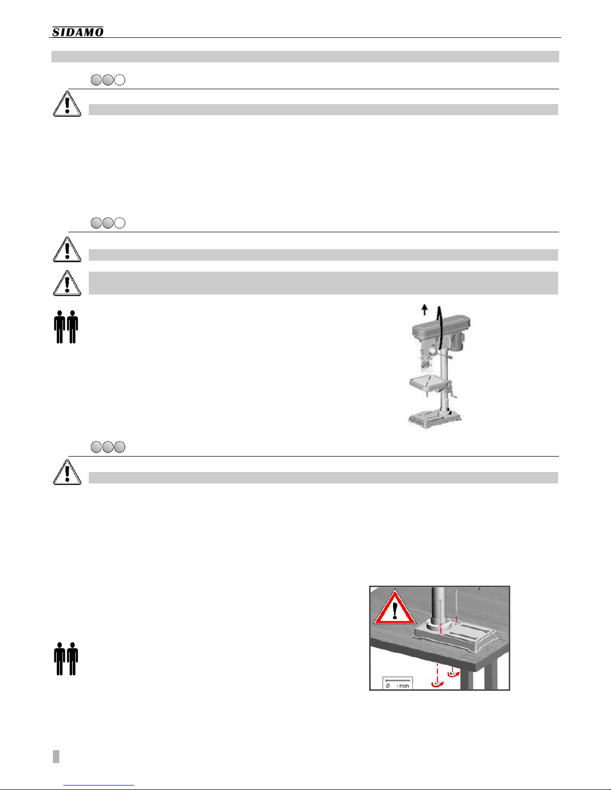
Considering the weight of the machine (49 kg),
several persons, using an adapted lifting device, are
required to install the machine.
To lift the machine, use a slinging system (ex :
polyester cable, with lifting rings and a convenient capacity).
Position the lifting device as shown on next figure.
Make sure all moving parts are securely fixed and be very
careful when lifting the drilling machine. Keep any foreign
person away.
5.3.
5.3.5.3.
5.3. INSTALLING THE MACH
INSTALLING THE MACH INSTALLING THE MACH
INSTALLING THE MACHINE
INEINE
INE
Only qualified and authorized persons can perform below operations.
Only qualified and authorized persons can perform below operations.Only qualified and authorized persons can perform below operations.
Only qualified and authorized persons can perform below operations.
Vicinity of the equipment :
Vicinity of the equipment :Vicinity of the equipment :
Vicinity of the equipment :
Main power should comply with the specifications
of the machine.
Ambient temperature : between +5°C and +35°C.
Relative Humidity : not over 90%.
Sufficient ventilation of the workshop.
Good lighting conditions in the working area : min.
300 lux.
Consider the location of the machine in the room.
Movements and movings should be easy. Respect a
distance of min. 800 mm between the back of the machine
and the wall.
Several persons are required to install the machine.
Position the machine on a flat and horizontal
surface, so that it is level and as stable as possible.
Use a strong enough support base for the machine.
Drill the fixing holes in the support. They must match base
holes. Fix the machine.
Prior to tightening bolt, make sure the machine is level. To
adjust level, use adapted metal sheets (reference shims)
between the surface of the support and the feet.
To perform machining while respecting ergonomic criteria,
the vice plane should be ideally positioned at about 90/95
cm from the floor.
12
User’s manual PE22A
9
Cleaning a new machine :
Cleaning a new machine :Cleaning a new machine :
Cleaning a new machine :
All our machines are supplied with rustproof oil on
ground surfaces. Before using the machine, first
remove this oil, using a thinner. This is very
important. Please use extreme care when
performing this cleaning : jammings can occur if
this oil is not totally removed.
There should be no chips and no oil residues on the
surface of the clamping table.
Once the machine has been cleaned, apply a thin
film of oil onto all non-painted surfaces, using
medium-viscosity oil.
Clean the inner part of both spindle and chuck,
using a dry cloth and firmly insert the Morse taper
into the spindle. Then, insert firmly the chuck into
the shank of the Morse taper.
5.4.
5.4.5.4.
5.4. ASSEMBLING
ASSEMBLING ASSEMBLING
ASSEMBLING
Only qualified and authorized persons can perform below operations.
Only qualified and authorized persons can perform below operations.Only qualified and authorized persons can perform below operations.
Only qualified and authorized persons can perform below operations.
Several persons are required to assemble
Several persons are required to assemble Several persons are required to assemble
Several persons are required to assemble the machine.
the machine.the machine.
the machine.
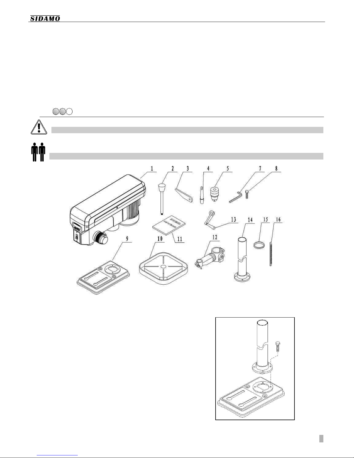
Figure 2
1. Install the base (9 fig.2) on a solid and flat surface.
2. Assemble the column (14 fig.2) to the base and fix
it using bolts (8 fig.2).
 Loading...