

Sicunet SHR-7004, SHR-7016, 7008, SHR-8004 User Manual

1
DVR SHR-7004/7008/7016/8004
Sicunet Inc.
3001 Red Hill Ave. Suite 2-205
Costa Mesa, CA 92626
www.sicunet.com
User Manual

2
Important Safety Instruction
Instruction and Warnings for Safety
Read these operating instructions carefully before using the unit. Follow all the safety
instructions listed below. Keep these operating instructions handy for future reference.
·
Read these instructions.
·
Keep these instructions.
·
Heed all warnings.
·
Follow all instructions.
·
Do not use this apparatus near water.
·
Clean only with dry cloth.
·
Do not block any ventilation openings, Install in accordance with the manufacturer’s
instructions.
·
Do not install near any heat sources such as radiators, heat registers, stoves, or other
apparatus (including ampliers) that produce heat.
·
Do not defeat the safety purpose of the polarized or grounding- type plug. A polarized plug
has two blades with one wider than the other. A grounding type plug has two blades and a third
grounding prong. The wide blade or the third prongs are provided for your safety. If the
provided plug does not t into your outlet, consult an electrician for replacement of the
obsolete outlet.
·
Protect the power cord from being walked on or pinched particularly at plugs, convenience
receptacles, and the point where they exit from the apparatus.
·
Only use attachments/accessories specied by the manufacturer.
·
Use only with the cart, stand, tripod, bracket, or table specied by the manufacturer, or
sold with the apparatus. When a cart is used, use caution when moving the cart/apparatus
combination to avoid injury from tip-over.
·
Unplug this apparatus during lightning storms or when unused for long periods of time.
Refer all servicing to qualied service personnel. Servicing is required when the apparatus
has been damaged in any way, such as power-supply cord or plug is damaged, liquid has
been spilled or objects have fallen into the apparatus, the apparatus

3
This user manual provides Information for using the DVR such as brief introduction,
part names, functions, connection to other equipment, menu setup, etc. Users have to
keep in mind the following notices.
·
Manufactures retains the copyright on this manual.
·
This manual cannot be copied without Manufacture’s prior written approval.
·
We are not liable for any or all losses to the product incurred by your use of non-standard
product or violation of instructions mentioned in this manual.
·
Prior to opening the case, please consult a qualied technician rst. Whenever this is needed
power must be removed from the unit.
·
Before installing an additional HDD or connecting an external storage device (USB memory or
USB HDD) to this DVR, check the compatibility. Consult your provider for the compatibility list.
Before Start
·
Replacement Battery or Hard Disk
It is essential that when changing the battery or HDD in the unit, the replacement must be
of the same type or recommended ones, otherwise there may be a possibility of damage or
explosion.
·
System Shutdown
Turning off the power while the product is in operation, or undertaking improper actions may
cause damage or malfunction to the hard drive or the product. Please turn off the power using
the Power button on the front of your DVR. After selecting <OK> in the pop-up menu, you can
pull off the power cord. You may want to install a UPS system for safe operation in order to
prevent damage caused by an unexpected power stoppage. (Any questions concerning UPS,
consult your UPS retailer.)
·
Operation Temperature
The guaranteed operating temperature range of this product is 0°C ~ 40°C (32°F ~ 104°F).This
product may not work properly if you run right after a long period of storage at a temperature
below the guaranteed one. Prior to using a device that has been stored for a long period in low
temperatures, allow the product to stand at room temperature for a period. Especially for the
built-in HDD in the product, its guaranteed temperature range is 5°C ~ 55°C (41°F ~ 131°F).
Likewise, the hard drive may not work at a temperature below the guaranteed one.
Warning

4
2.1 COMPRESSION FORMAT 8
2.2 LIVE SURVEILLANCE 8
2.3 RECORD MEDIA 8
2.4 BACKUP 8
2.5 RECORD & PLAYBACK 8
2.6 ALARM 9
2.7 PTZ CONTROL 9
2.8 SECURITY 9
2.9 NETWORK 9
Content
7
10
1. Overview
1. Open-package Check
3. Front Panel Description
6. Control with Mouse
8
11
12
17
Chapter 1
Chapter 2
Product Introduction
Getting Started
2. Main Features
2. Install Hard Drive
5. Remote Controller
4. Rear Panel Description
7. Login
8
11
16
14
17

5
Content
19
20
21
21
21
21
21
21
22
22
22
22
22
22
23
23
23
24
25
25
1. Control Menu 20
Chapter 3
Menu Setup Guide
1.1 Live Preview
1.2 Control
1.2.1 PTZ
1.2.2 E-Zoom
1.2.3 Audio
1.2.4 Color
1.2.5 Dwell
1.2.6 Snap
1.2.7 Manual Alarm
1.3 Status
1.3.1 Event
1.3.2 Network
1.3.3 Users
2.1 Playback
2.2 Search
2.2.1 Time Search
2.2.2 Event Search
2.2.3 File Management
2.3 Quick Setup (WIZARD)
2. Main Menu 23

6
Content
2.4 Setup
2.4.1 System
2.4.2 Record
2.4.3 Network
2.4.4 Device
2.4.5 Event
2.4.6 Reset
2.4.7 Import/Export
2.5 Backup
2.6 Tools
2.6.1 Storage Manager (Disk Management)
2.6.2 System Log
2.7 System Info
2.8 Logout
2.9 Reboot
49
50
51
Appendix A
Appendix B
Appendix C
FAQ
Compatible Devices
Specications
26
26
30
34
37
41
46
46
47
48
48
48
48
48
48

7
Chapter 1
Product Introduction

02
Main Features
8
This model of DVR (Digital Video Recorder) is designed for high performance CCTV solutions. It adopts
state of the art video processing chips and embedded Linux system.
2.1 COMPRESSION FORMAT
• Standard H.264 compression with low bit rate and better image quality
2.2 LIVE SURVEILLANCE
• Support HDMI 1080P output
• Support channel security by hiding live display
• Display the local record state and basic information
• Support USB mouse to make full control
2.3 RECORD MEDIA
• Support a SATA HDD to record (HDD le system is FAT32 format) for a longer time without any limitation
2.4 BACKUP
• Support USB 2.0 devices to backup
• Support saving recorded les to a remote computer through internet
2.5 RECORD & PLAYBACK
• Record modes: Manual, Schedule, Motion detection and Sensor alarm recording
• Support recycle after HDD full
• Resolution, frame rate and picture quality are adjustable
• 1 or 4 audio channels available
• Support multi-channel playback simultaneously
• Support deleting and locking the recorded les one by one
• Four record search mode: time search, event search, le management and image search
• Support remote playback in Network Client through LAN or internet
Overview
Product Introduction
01

9
2.6 ALARM
• Support multi-channel alarm input and alarm output available
• Support schedule for Motion detection and Sensor alarm
• Support pre-alarm recording and post-alarm recording
• Support linked channels recording once motion or alarm triggered on certain channel
• Support linked PTZ preset, cruise and track
• Support linked sending alarm email
• Support linked snap picture
2.7 PTZ CONTROL
• Support various PTZ protocols
• Support 128 PTZ presets and 8 cruise lines
• Support remote PTZ control through internet
2.8 SECURITY
• Customize user right
• Support 1 administrator and 63 users
• Support event log recording and checking
2.9 NETWORK
• Support TCP/IP, DHCP, PPPoE, DDNS protocol
• Support browser to do remote view
• Support setup client connection amount
• Support dual stream. Network stream is adjustable independently to t the network bandwidth and
environment
• Support various controls over the network
• Support remote search and channel playback
• Support remote PTZ control
• Support remote full menu setup and remote parameter change
• Support CMS to manage multi devices on internet
Product Introduction

10
Chapter 2
Getting Started
Open-package Check
Install Hard Drive
02
Fig 2-1
11
When you receive the DVR, please check the unit and the accessories:
First, please check whether there is any visible damage to the package appearance.
Then, please open the box. Check whether there is any visible damage to the DVR appearance.
At last, please open the machine crust and check the data wire, power wire, the connection between the fan
power and the main board.
Front panel and rear panel
• The key function specication in the front panel and the interface specication in the real panel are in
the user manual.
• Please check the product type in the front panel whether is accordant with the product type you order.
The label in the rear panel is very important for the after-sale services. Please protect it carefully. When you
contact us for after-sale service, please provide the product type and serial number in the label.
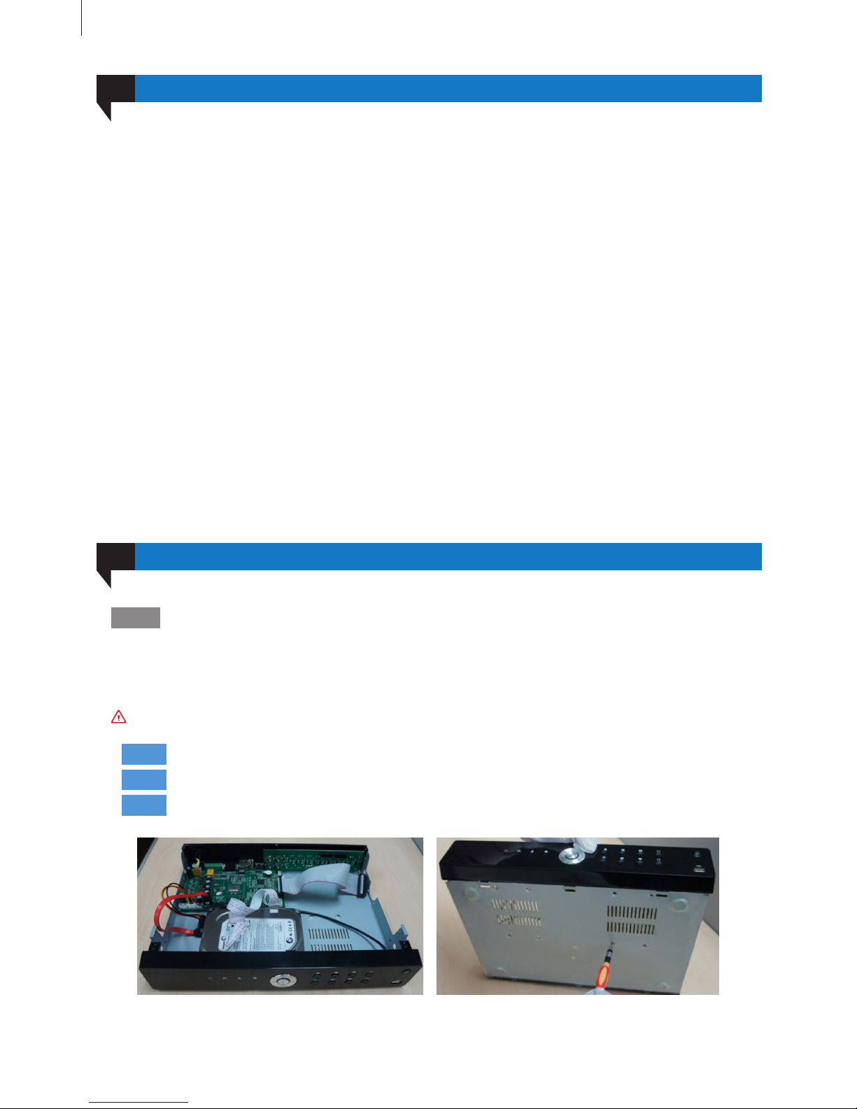
DVR supports one or two hard disk. Please use the hard drive recommended by the manufacturers for
security and safe eld. Please refer to “Appendix B Compatible Devices 2”.
01
Step1
Note :
Step2
Step3
Disassemble the screw and open the top cover.
Connect the power and data cables. Place the HDD onto the bottom case as Fig 2-1.
Mount the HDD.
Please disconnect the power before being connected to other devices. Don’t hot plug in/out.
Getting Started
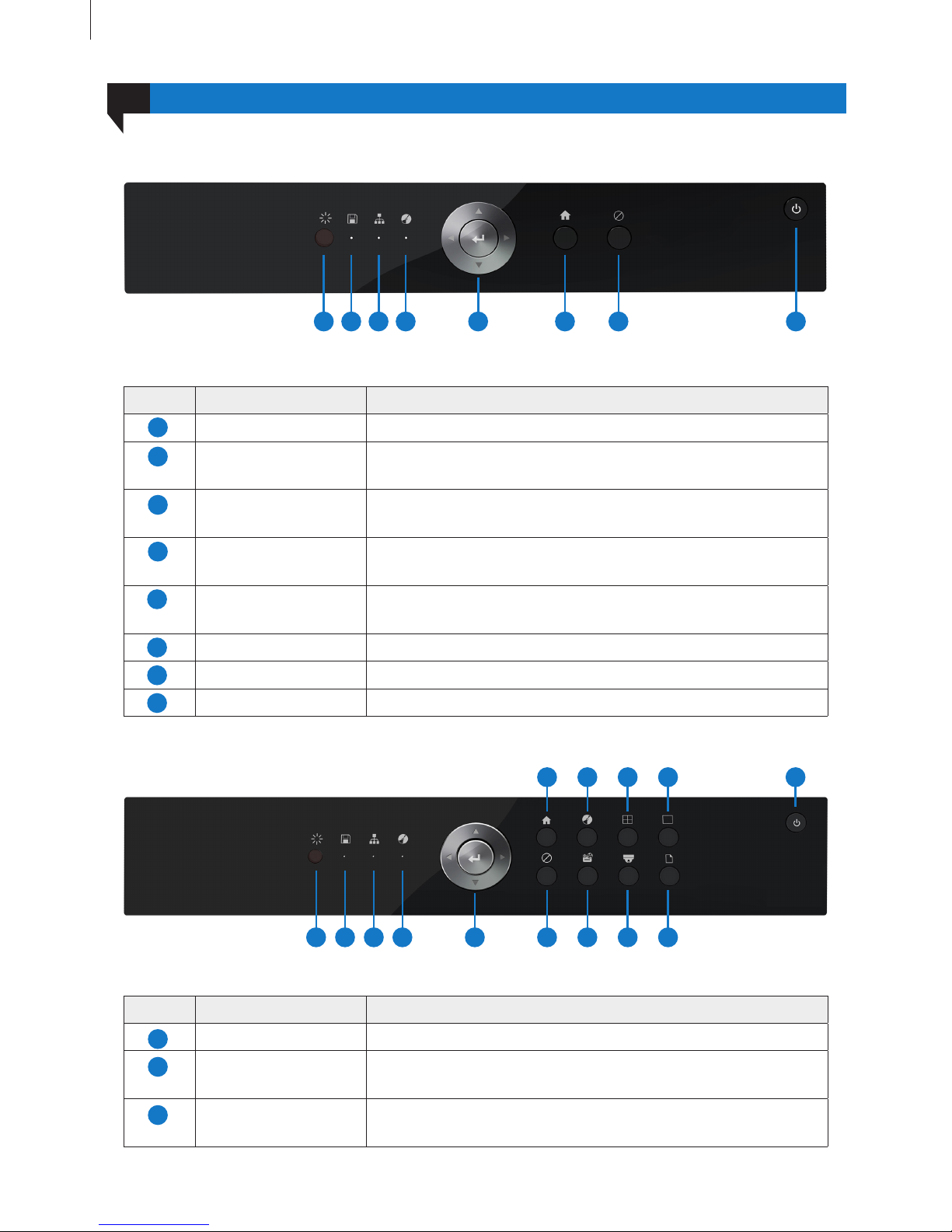
Fig 2-2
Front Panel Description
Fig 2-3
Item Name Description
IR Receive the signal of remote controller.
HDD Hard disk status indicator.
When HDD is writing or reading, the light is white.
Network Network connection indicator.
When the network connection is successful, the light is white.
12
Item Name Description
IR Receive the signal of remote controller.
HDD Hard disk status indicator.
When HDD is writing or reading, the light is white.
Network Network connection indicator.
When the network connection is successful, the light is white.
Rec Recording status indicator.
When recording, the light is white.
Direction and Enter Direction keys: change direction to select items.
Enter key: conrm selection.
Menu Go to the Main Menu.
Cancel Return to the previous menu or interface.
Power Power on/off the DVR.
03
1) SHR-7004
Getting Started
2) SHR-7008
1 2 3 10
6
12
8
4 11
7
13
9 14
5
1
3
2
1
3
2
4
1 2 3 64 7 85
5
7
6
8

Rec Recording status indicator.When recording, the light is white.
Direction and Enter Direction keys: change direction to select items.
Enter key: conrm selection.
Menu Go to the Main Menu.
Rec Manual recording switch.
Multi Switch to multi-screen preview.
Single Switch to single screen preview.
Cancel Return to the previous menu or interface.
Playback Playback control.
PTZ PTZ control.
Network Status Check the network information.
Power Power on/off the HD-SDI DVR.
Fig 2-4
Item Name Description
IR Receive the signal of remote controller.
HDD Hard disk status indicator.
When HDD is writing or reading, the light is white.
Network Network connection indicator.
When the network connection is successful, the light is white.
Rec Recording status indicator.When recording, the light is white.
Direction and Enter Direction keys: change direction to select items.
Enter key: conrm selection.
Menu Go to the Main Menu.
Rec Manual recording switch.
Multi Switch to multi-screen preview.
Single Switch to single screen preview.
Cancel Return to the previous menu or interface.
Playback Playback control.
PTZ PTZ control.
Network Status Check the network information.
13
10
5
12
7
14
9
4
11
6
13
8
Getting Started
3) SHR-7016/8004
1 2 3 10
6
12
8
4 11
7
13
9
15
14
5
1
3
10
5
12
7
2
9
4
11
6
13
8

Rear Panel Description
Fig 2-5
Item Name Description
V-IN Video signal input.
A-IN Audio input: connect to pickup and other audio collecting equipment.
A-OUT Audio output: connect to sound box and other audio output equipment.
V-OUT CVBS video signal output: connect to monitor with BNC interface.
HDMI port HD 1080P video signal output: connect to high-denition display.
LAN port Network connector.
VGA port VGA output: connect to monitor.
USB port USB connector: connect to USB mouse, USB disk, mobile HDD, etc.
RS-485 RS-485 communication port: connect to PTZ, keyboard, etc.
DC 12V Power input: DC 12V
Fig 2-6
Power Power on/off the HD-SDI DVR.
USB Port Connect to USB mouse, USB disk, mobile HDD, etc.
14
14
15
04
Getting Started
1
3
10
5
7
2
9
4
6
8
1) SHR-7004
103
1 2 7
4 5 6 8 9
2) SHR-7008
103
1 2 7
4 5 6 8 9
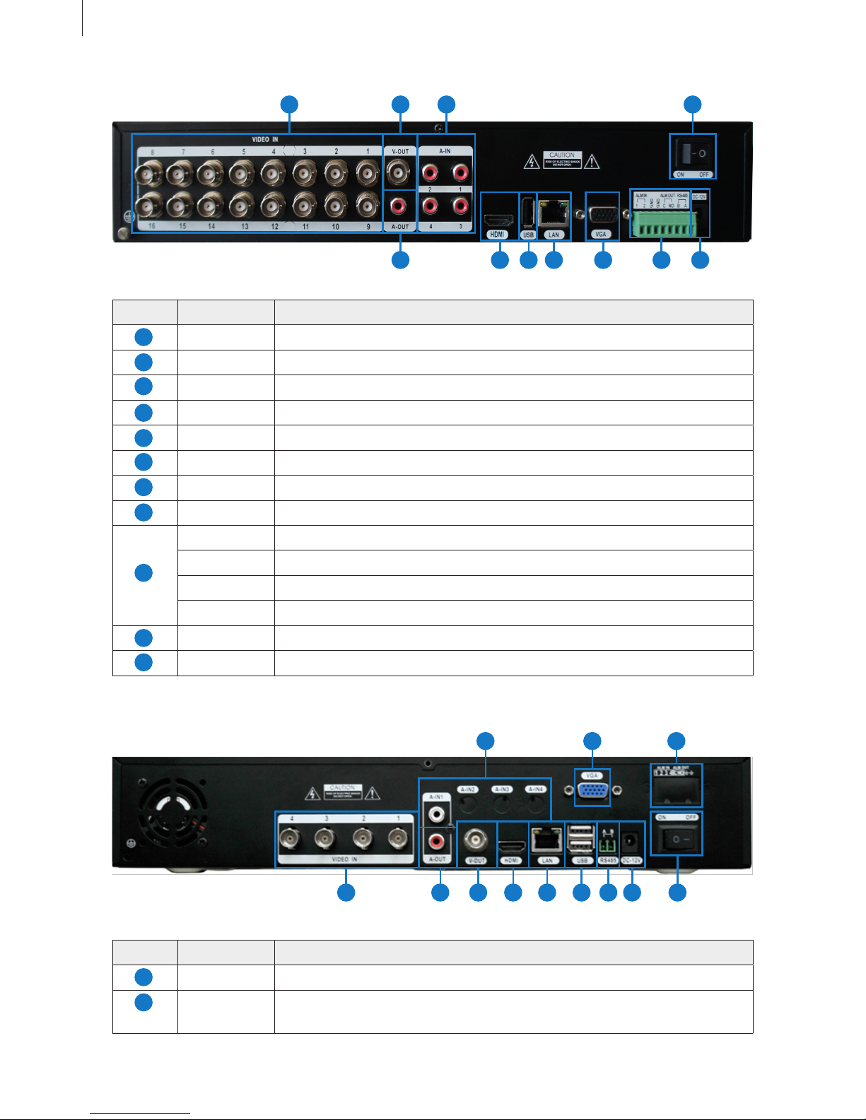
Fig 2-7
Fig 2-8
Item Name Description
VIDEO IN Video signal input.
V-OUT CVBS video signal output: connect to monitor with BNC interface.
A-IN Audio input: connect to pickup and other audio collecting equipment.
A-OUT Audio output: connect to sound box and other audio output equipment.
HDMI port HD 1080P video signal output: connect to high-denition display.
USB port Connect to USB mouse, USB disk, mobile HDD, etc.
LAN port Network connector.
VGA port VGA output: connect to monitor.
ALM IN Alarm input: connect to external alarm sensor.
ALM OUT Alarm output: connect to external alarm output device.
RS-485 RS-485 communication port: connect to PTZ, keyboard, etc.
GND Grounding
DC 12V Power input: DC 12V
Power Switch Turn on/off the power.
Item Name Description
VIDEO IN Video signal input from HD-SDI Cameras.
A-IN 4ch audio input: connect to microphone and other audio collecting
equipment.
15
Getting Started
3) SHR-7016
104
1 2 3 11
5 6 7 8 9
4) SHR-8004
1
3
10
11
5
7
2
9
4
6
8
1
2
1231
2 10 11
4 5 6 7 8 9
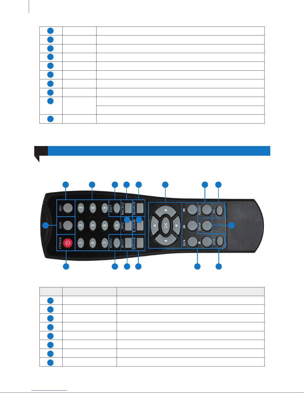
Remote Controller
05
Fig 2-9 Remote Controller
A-OUT 1ch audio output: connect to sound box and other audio output equipment.
V-OUT CVBS video signal output: connect to monitor with BNC interface.
HDMI Port HD 1080P video signal output: connect to high-denition display.
LAN Port Network connector.
USB Port Connect to USB mouse, USB disk, mobile HDD, etc.
RS-485 Connect to keyboard.
DC 12V Power input: DC 12V
VGA Port VGA output: connect to monitor.
ALARM
IN/OUT
ALM IN: 4ch alarm output: connect to external alarm sensor.
ALM OUT: 1ch alarm input: connect to external alarm output device.
Power Switch Turn on/off the power.
16
Getting Started
12
The remote controller of this product series uses two AAA size batteries and works after loading batteries:
Item Name Function
REC Button To start the manual recording.
ADD Button Input the number of DVR to control it.
POWER Button To turn on/off the device.
Digital Button Code input/number input/channel switch.
EXIT Button Return to the previous interface.
BACKUP Button To enter the backup mode.
SEARCH Button To enter the video playback interface.
SEQ Button To enter the auto dwell mode.
3
10
11
5
7
9
4
6
8
3 10 11 12 17 18
1 4 5 6 7 13 14 15
2 16
8 9
1
3
5
7
2
4
6
8
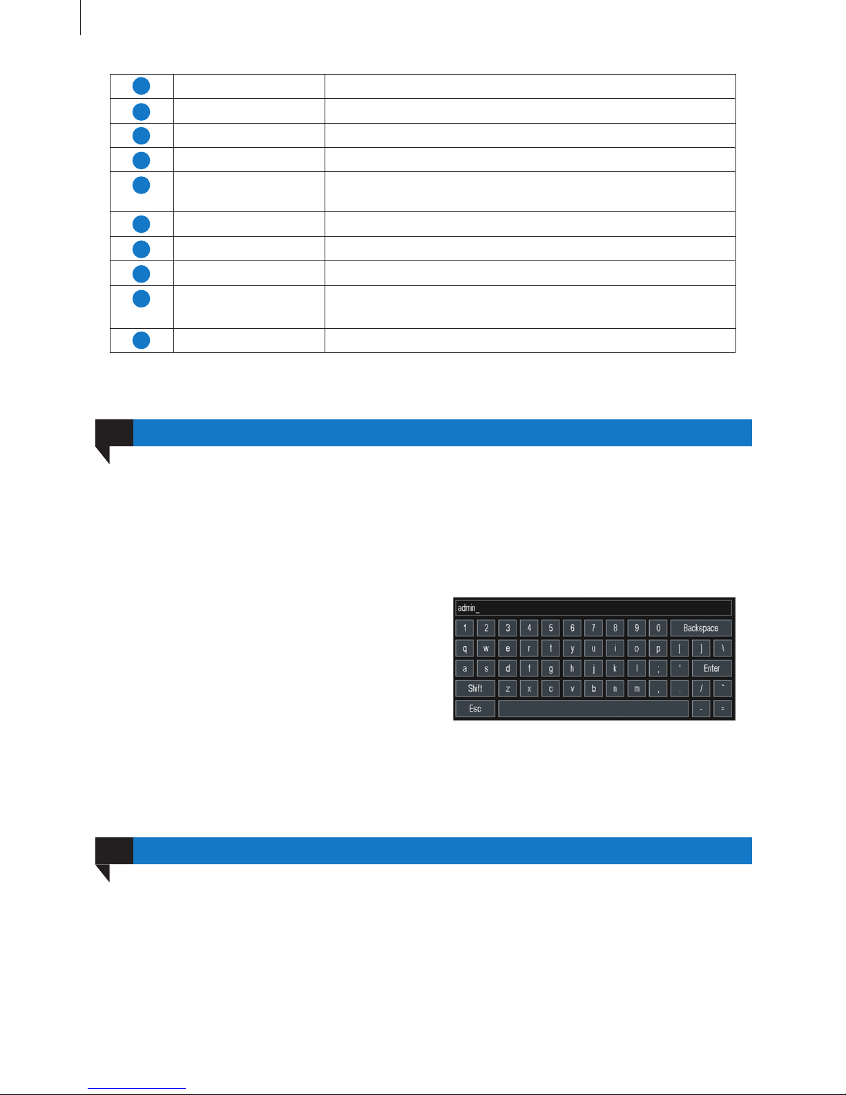
Fig 2-10
Login
07
17
It supports USB mouse through the USB ports.
In live: Double-click left button on one camera to be full screen display. Double-click again to return to the
previous screen display.
Click right button to show the control menu. Here are all control and setup. Click right mouse again to hide
the control menu.
In setup: Click left button to enter. Click right button
to cancel setup, or return to the previous.
If want to input the value, move cursor to the blank
and click. An input window will appear as Fig 2-10.
It supports digitals, letters and symbols input.
In playback and backup: Click left button to choose the options. Click right button to return to live mode.
Getting Started
E-ZOOM Button To electronic amplify the single channel.
MENU Button To enter the sub menu.
Multi Screen Button To choose multi-screen display mode.
Single Screen Button To choose single -screen display mode.
Direction and
Enter Button
Direction Button: move cursor to select items.
AUDIO Button To enter the audio adjustment interface.
Fn Button Reserved function keys.
SNAP Button To snap the live pictures.
Playback Control
Button
To control playback, pause/play, single-frame play, rewind, stop,
fast forward.
PTZ Button To enter the PTZ control interface.
Control with Mouse
06
User needs to login rst after system start, otherwise you cannot do any other operations except changing
the screen display mode. Double-click any preview window or click on any menu item to pop up the login
window. Input user name and password, then click “Login” button to continue operation, as shown in Fig
2-11:
11
13
15
17
9
12
14
16
18
10
 Loading...