

SICK IVP Ranger E/D, Ranger E, Ranger D Operating Instructions Manual
Ranger E/D
Operating Instructions
O PERATING I NSTRUCTIONS

© SICK IVP 2006-11-16
All rights reserved
8011731
Subject to change without prior notice.
Please read the complete manual before attempting to operate your Ranger.
WARNING
Turn off power before connecting
Never connect any signals while the Ranger unit is powered.
Never connect a powered Ranger E/D Connection terminal or powered I/O signals to a
Ranger.
Do not open the Ranger
The Ranger unit should not be opened. The Ranger contains no user serviceable parts
inside.
Safety Hints if used with laser equipment
Ranger is often supposed to be used in combination with laser products.
The user is responsible to comply with all laser safety requirements according to the laser
safety standards IEC 60825 – 1 (2001-08) and 21 CFR 1040.10/11 (CDRH) respectively.
Please read the chapter “Laser Safety” in Appendix B carefully.
Turn off the laser power before maintenance
If the Ranger is used with a laser (accessory), the power to the laser must be turned off
before any maintenance is performed. Failure to turn this power off when maintaining the
unit may result in hazardous radiation exposure.
ISM Radio Frequency Classification - EN55011 - Group1, Class A
Class A equipment is intended for use in an industrial environment. There may be potential
difficulties in ensuring electromagnetic compatibility in other environments, due to conducted as well as radiated disturbances.
Explanations:
Group1 – ISM equipment (ISM = Industrial, Scientific and Medical)
Group 1 contains all ISM equipment in which there is intentionally generated and/or used
conductively coupled radio-frequency energy which is necessary for the internal functioning of the equipment itself.
Class A equipment is equipment suitable for use in all establishments other than domestic
and those directly connected to a low voltage power supply network which supplies buildings used for domestic purposes.
Class A equipment shall meet class A limits.
Note: Although class A limits have been derived for industrial and commercial establishments, administrations may allow, with whatever additional measures are necessary, the
installation and use of class A ISM equipment in a domestic establishment or in an establishment connected directly to domestic electricity power supplies.
Please read and follow ALL Warning statements throughout this manual.
Windows and Visual Studio are registered trademarks of Microsoft Corporation.
All other mentioned trademarks or registered trademarks are the trademarks or registered trademarks of their
respective owner.
a

Operating Instructions
Ranger E/D
8011731 SICK IVP • Industrial Sensors • www.sickivp.com • All rights reserved 3
Contents
Contents
1 Introduction ...................................................................................................................................4
2 Installation Guide .......................................................................................................................... 6
2.1 Preparations ............................................................................................................................ 6
2.1.1 PC Hardware Requirements...................................................................................... 7
2.1.2 Preparing the Network............................................................................................... 7
2.2 Mounting the Ranger............................................................................................................... 8
2.3 Connecting the Ranger............................................................................................................ 9
2.4 Installing Ranger Software ....................................................................................................10
2.5 Getting an Image from the Ranger .......................................................................................11
2.6 Maintenance.......................................................................................................................... 12
2.7 Service ..................................................................................................................................12
3 Overview.......................................................................................................................................13
3.1 Measuring with the Ranger................................................................................................... 13
3.2 Mounting the Ranger.............................................................................................................14
3.3 Configuring the Ranger..........................................................................................................15
3.3.1 Ranger Studio ..........................................................................................................15
3.3.2 Measurement Methods ...........................................................................................16
3.4 Developing Applications........................................................................................................ 20
3.5 Triggering ...............................................................................................................................21
4 Hardware Description .................................................................................................................22
4.1 Sensor ..................................................................................................................................22
4.1.1 Light Sensitivity ........................................................................................................ 22
4.2 Electrical Connections........................................................................................................... 23
4.3 Technical Data.......................................................................................................................25
4.4 Dimensional Drawing ............................................................................................................ 26
Appendix ............................................................................................................................................27
A Ranger E and D Models.........................................................................................................27
B Laser Safety...........................................................................................................................28
C Recommended Network Cards.............................................................................................29
D Recommended Switches.......................................................................................................30
E iCon Device Configuration..................................................................................................... 30
F Connecting Encoders.............................................................................................................31
G Ranger E/D Power-I/O terminal............................................................................................33
H Laser Safety Key Box (ICT-B).................................................................................................35

Chapter 1 Operating Instructions
Ranger E/D
4 SICK IVP • Industrial Sensors • www.sickivp.com • All rights reserved 8011731
Introduction
1 Introduction
The Ranger is a high-speed 3D camera intended to be the vision component in a machine
vision system. The Ranger makes measurements on the objects that passes in front of the
camera, and sends the measurement results to a PC for further processing. The measurements can be started and stopped from the PC, and triggered by encoders and photoelectric switches in the vision system.
Figure 1.1 – The Ranger as the vision component in a machine vision system
The main function of the Ranger is to measure 3D shape of objects. Depending on model
and configuration, the Ranger can measure up to 35 000 profiles per second.
In addition to measure 3D – or range – the Ranger can also measure intensity and scatter:
Range measures the 3D shape of the object by the use of laser triangulation. This can
be used for example for generating 3D images of the object, for size rejection
or volume measurement, or for finding defects on the object if it has a wellknown shape.
Intensity measures the light that is reflected by the object. This can be used for example
for inspecting print on objects or detecting defects in the objects’ surface.
Scatter measures how the incoming light is distributed beneath the object’s surface.
This is useful for example for finding the fiber direction in wood or detecting
delamination defects.
Operating Instructions Chapter 1
Ranger E/D
8011731 SICK IVP • Industrial Sensors • www.sickivp.com • All rights reserved 5
Introduction
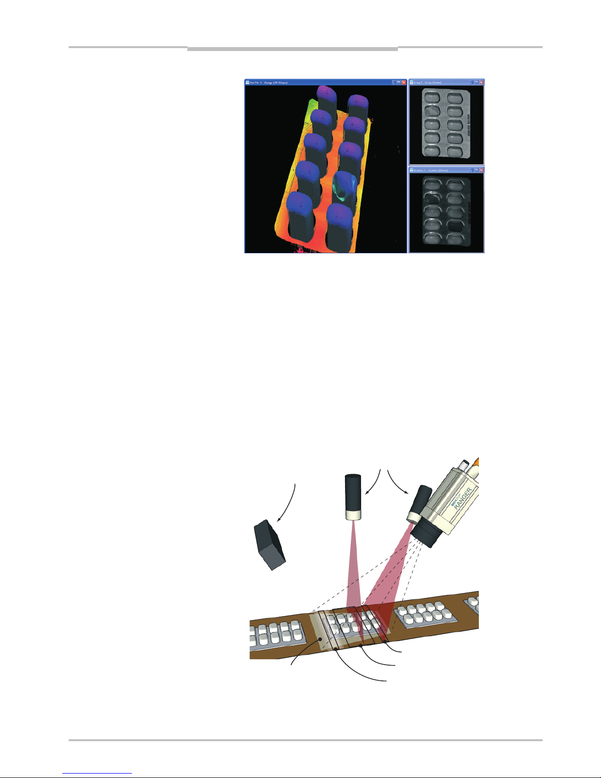
Figure 1.2 – 3D (left), intensity (top right), and scatter (bottom right) images of a blister
pack with one damaged blister and two empty blisters.
There are three different models of the Ranger available:
Ranger C Connects to the PC via CameraLink.
Ranger E Connects to the PC through a Gigabit Ethernet network.
Ranger D A low-cost, mid-performance version of the Ranger E, suitable for measuring
3D only in applications without high-speed requirements. The Ranger D can
measure up to 1000 profiles per second.
The Ranger C and E models are MultiScan cameras, which mean that they can make
several types of measurements on the object in parallel. This is achieved by applying
different measurement methods to different parts of the sensor.
By selecting appropriate illuminations for the different areas of the measurement scene,
the Ranger can be used for measuring several features of the objects at the very same
time.
Figure 1.3 – Measuring several properties of the objects at once with MultiScan, using
multiple light sources.
Field-of-vie
w
Scatte
r
3D measurement
Grayscale
White light
Lasers
Chapter 2 Operating Instructions
Ranger E/D
6 SICK IVP • Industrial Sensors • www.sickivp.com • All rights reserved 8011731
Installation Guide
2 Installation Guide
2.1 Preparations
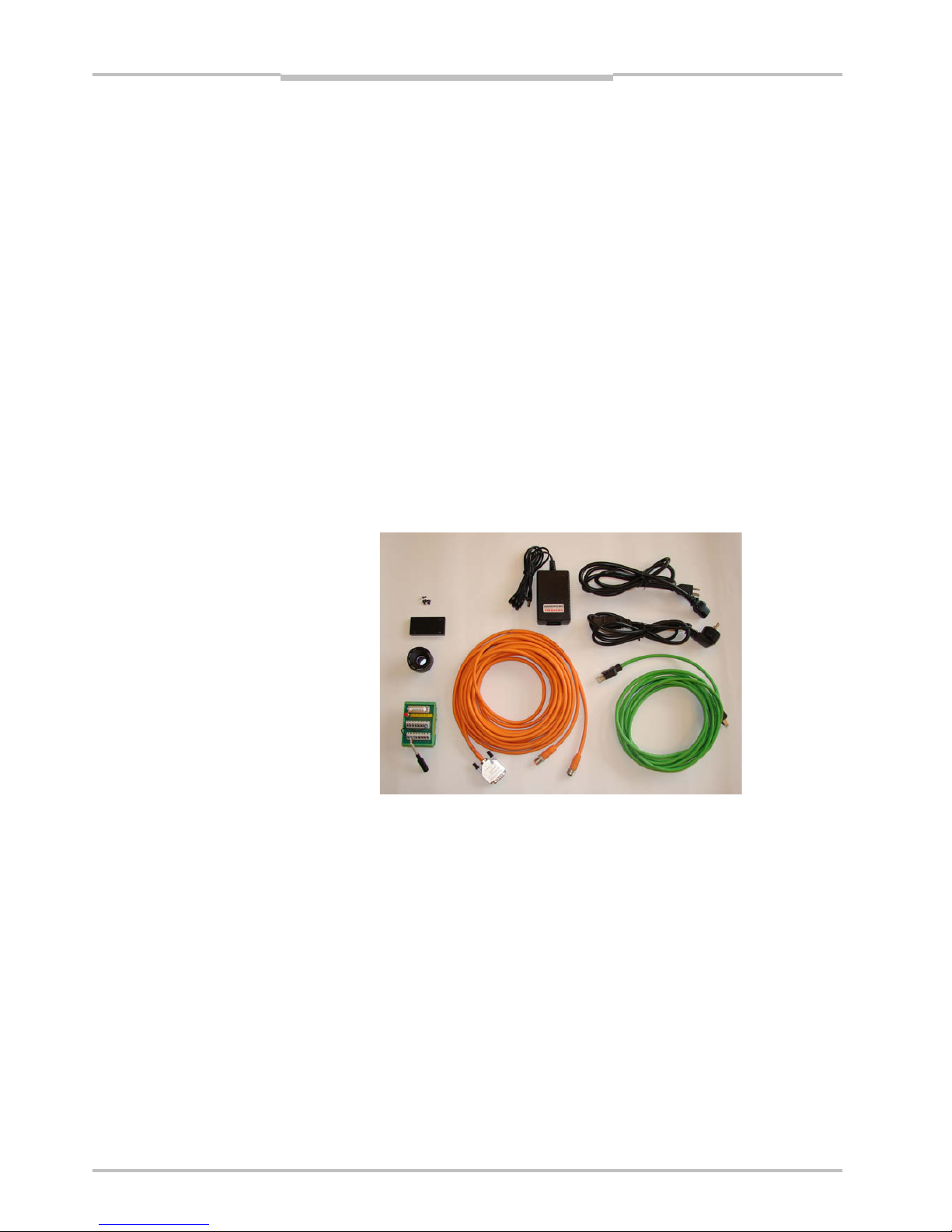
The following parts are recommended for getting started with the Ranger:
The Ranger E or D camera
A PC with a network interface card (NIC) that supports Gigabit Ethernet (for information
on requirements, see Appendix)
A Ranger E/D accessory kit:
– A Ranger E/D Power-I/O terminal
– An Ethernet cable for Gigabit Ethernet (5 m)
– A Power IO–Encoder Y-cable (2xM12 female – D-SUB male, 2 m)
– A lens, 25 mm F1.4, C-mount 1” optics
– Camera mounting parts
– A power supply (24 V DC wide range power supply with 1m cable and a standard
power input to support US/Europe cord)
– Operating Instructions (printed)
Ranger E/D Development software CD (including Ranger Studio)
Line-projecting laser, 660 nm
Laser triangulation parts
Figure 2.1 – Ranger E accessory kit
Some of parts listed above are recommended but not required for a working Ranger
system. For a minimal Ranger system the following parts are required:
A Ranger E or D camera
A 24 V DC power supply
A C-mount lens
A laser or other suitable light source
A PC with an Ethernet network interface
An Ethernet cable for camera control and data streaming
A PC application that communicates with the Ranger
Operating Instructions Chapter 2
Ranger E/D
8011731 SICK IVP • Industrial Sensors • www.sickivp.com • All rights reserved 7
Installation Guide
Warning:
Where ever Ranger is used in combination with a laser, all requirements for laser products
and laser systems according to the laser safety standards IEC 60825 – 1 (2001-08) and
21 CFR 1040.10/11 must be fulfilled. Please read chapter ”Laser Safety” in Appendix B
carefully.
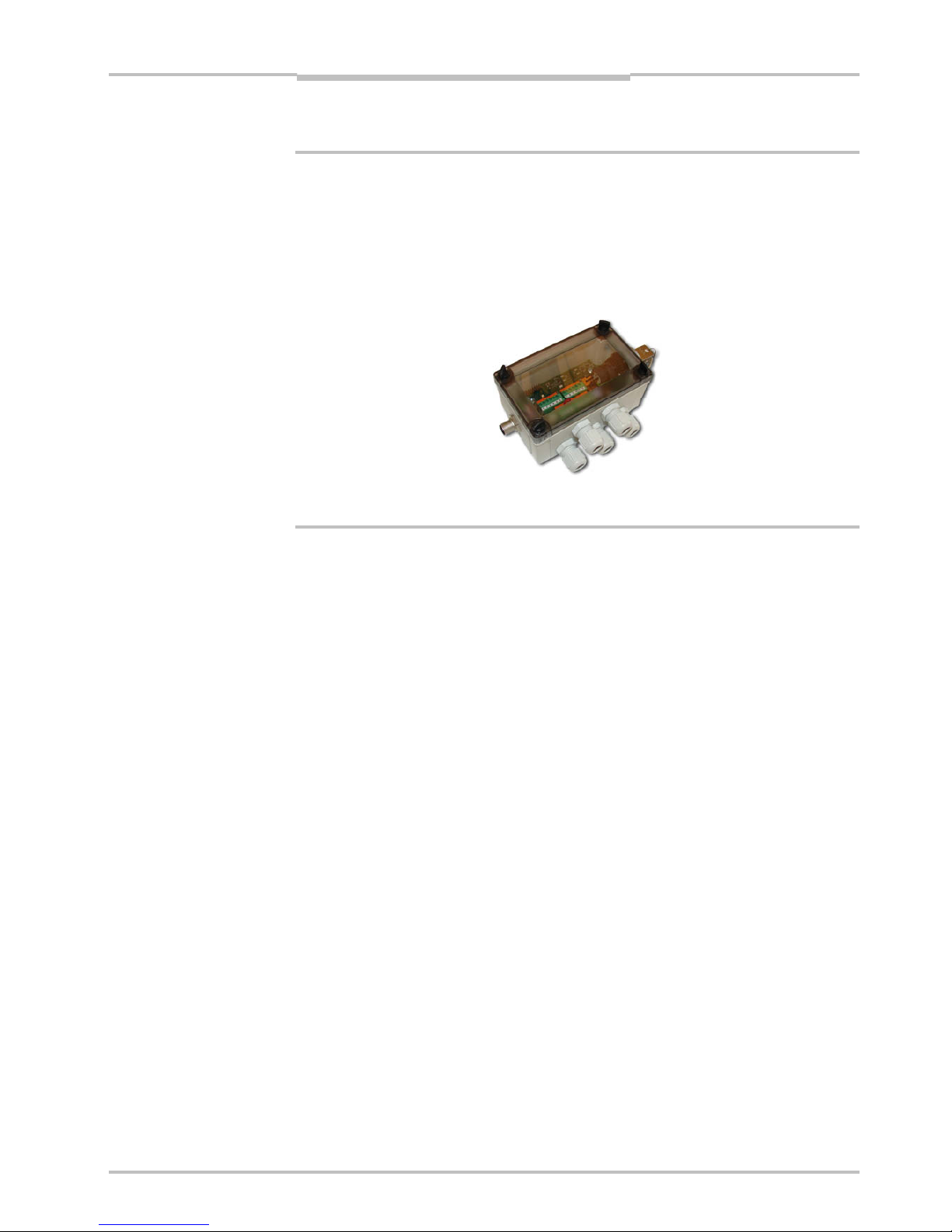
To handle class IIIb/ 3B lasers in an easy way, a laser safety box which provides a keyactuated master control, a remote interlock connection, a connection for an external
warning lamp and a delayed power-on, is available as accessory.
Figure 2.2 – ICT-B Laser safety box
2.1.1 PC Hardware Requirements
Recommended PC requirements for a Vision system:
AMD Athlon XP 2000+ or Intel P4 2.0 GHz
1024 MB RAM
800 MHz bus speed
1024*768 @ 24 bits of color
Windows XP Pro
A Gigabit Ethernet network interface card
For evaluation purposes, a PC with lower specifications may be sufficient.
2.1.2 Preparing the Network
Due to the large amount of data that the Ranger delivers, it is required to connect them to
the PC using a dedicated Gigabit Ethernet network, without other interfering traffic. If the
PC must be connected to other equipment, for example network printers, the PC should be
equipped with two network interface cards (NIC).
Many PCs today are delivered with a standard NIC for connection to an office network. This
NIC may not support Gigabit Ethernet, and even if it does it may cause performance problems when used with Rangers. Therefore the PC should always use one of the recommended NIC for Ranger related traffic.
A single Ranger can be connected with or without using a switch. Multiple Rangers are
preferably connected using a switch.
Information about recommended network interface cards and switches can be found in
Appendix C.
Chapter 2 Operating Instructions
Ranger E/D
8 SICK IVP • Industrial Sensors • www.sickivp.com • All rights reserved 8011731
Installation Guide
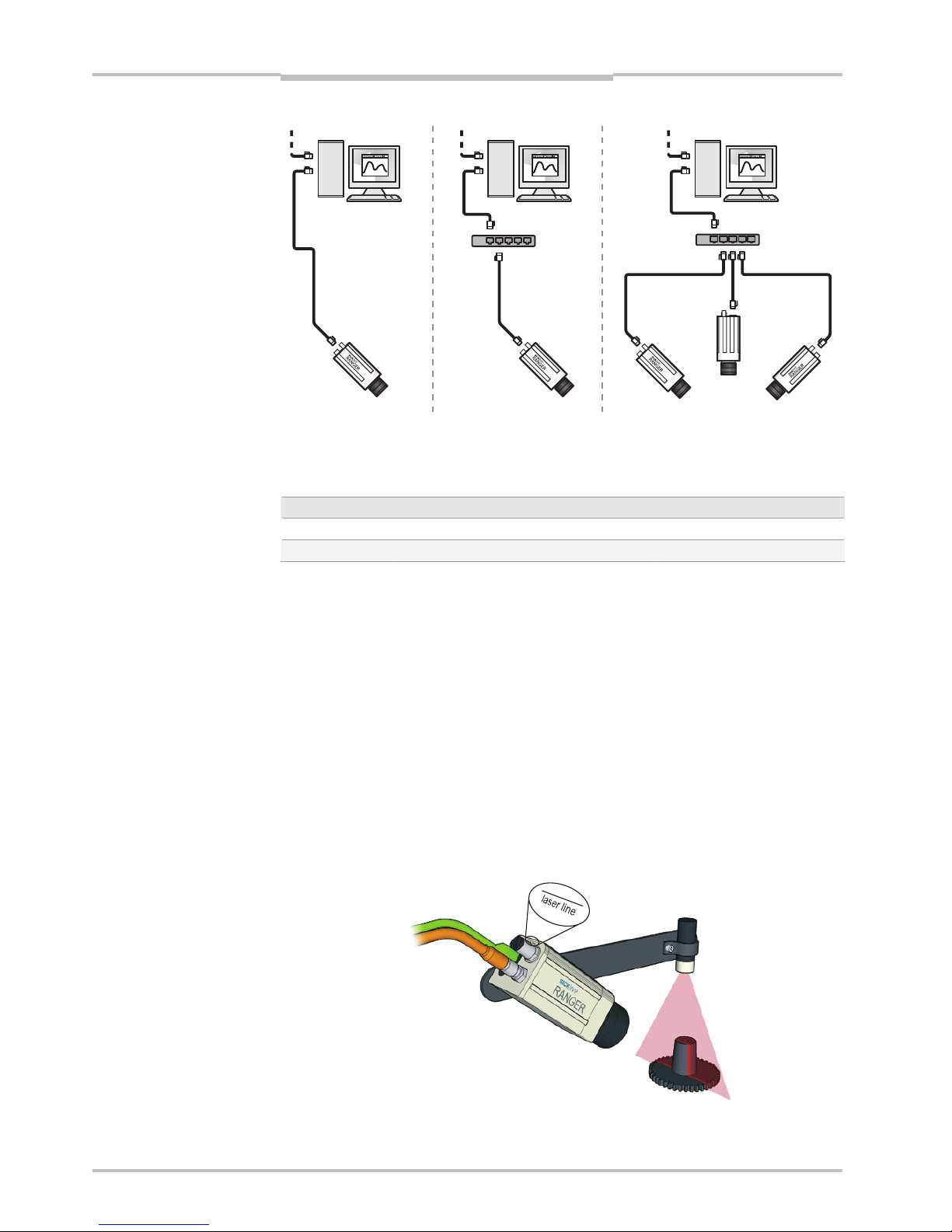
Figure 2.3 – Recommended ways of connecting one or more Rangers to a PC
The recommended IP settings:
Device IP address within the range Net mask
PC 192.168.0.1 – 192.168.0.10 255.255.255.0
Camera 192.168.0.11 – 192.168.0.254 255.255.255.0
Each Ranger needs a unique IP address when connected in a network. The Rangers are
delivered with IP addresses, which by default will work in most cases. If necessary, the IP
address of the Ranger can be changed by using the iCon Device Configuration utility.
Information on using iCon Device Configuration can be found in Appendix E.
2.2 Mounting the Ranger
When measuring range, the Ranger is used together with a line-projecting laser line that
illuminates the cross-section of the object to be measured. The Ranger and the laser
should be mounted so that the laser illuminates the object from one direction, and the
Ranger views the object from another direction.
The Ranger and the laser line should be oriented so that the laser line will appear along
the sensor in the Ranger. The Laser line mark on the back of the Ranger indicates in which
direction the Ranger will expect the laser line to be.
Exactly how to mount the Ranger and the laser depends on a whole number of factors. For
more information, see “Mounting Rangers and Lightings” in the Reference manual.
Figure 2.4 – Mounting the Ranger and a laser for measuring range.
PC
Switch
PC PC
Switch
Other network
Operating Instructions Chapter 2
Ranger E/D
8011731 SICK IVP • Industrial Sensors • www.sickivp.com • All rights reserved 9
Installation Guide
For best result it is also important to shield out direct sun light and other disturbing light
from the field of view.
It is also important to select a lens that is suitable for the field-of-view in which the Ranger
should measure. Select a high-quality lens that gives sharp images and low distortion, as
this can be essential for achieving a successful vision application.
The Ranger E has four mounting holes on each side, and two additional holes on the
bottom side near the front. The accuracy in location relative to the sensor is higher for the
two front holes than for the other holes. For drilling instructions, dimensions and further
information, see the Hardware Description on page 22.
2.3 Connecting the Ranger
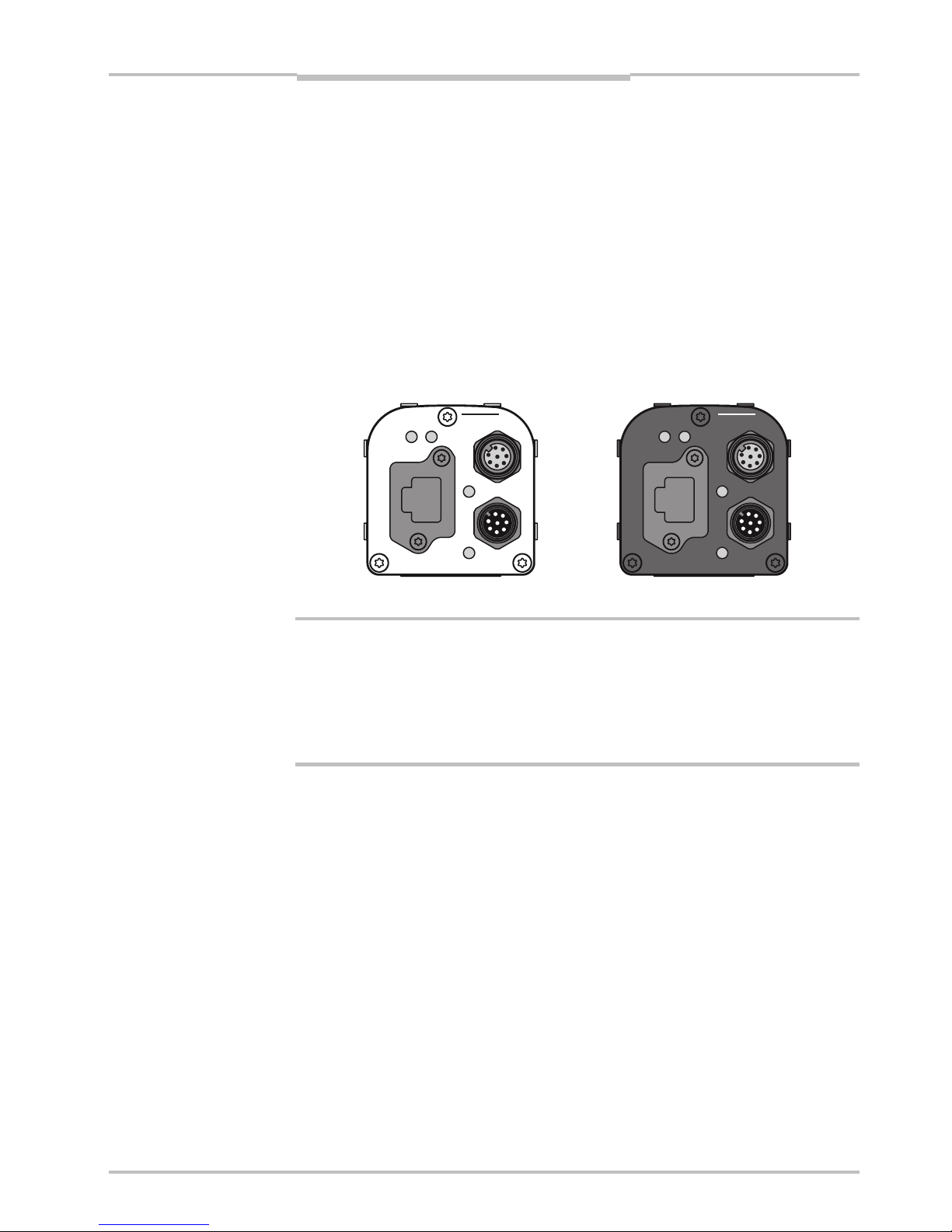
The following figure shows the position of the connectors on the back of the Ranger. For
more information on wiring and signals on the connectors, see the Hardware Description
on page 22.
encoder
Gigabit Ethernet
data
laser line
link
function on
power
encoder
Gigabit Ethernet
data
link
function on
power
laser line
Figure 2.5 – Connectors on the Ranger E and D respectively.
Warning!
Never connect any signals while the Ranger unit is powered.
Never connect a powered Ranger E/D Power-I/O terminal or powered I/O signals to a
Ranger.
If the laser trigger signal is used for lighting the laser, the laser may become activated as
soon as the Ranger is powered on. Do not look into the laser beam. Avoid looking at the
laser reflection.
Follow the following steps to prepare the Ranger for operation.
1. Ensure that all laser safety requirements are fulfilled for the applicable laser system
according to the standards IEC 60825-1 (2001-08) and 21 CFR 1040.10 / 11
(CDRH). See ”Laser Safety” in Appendix B for details.
2. Remove the protection caps covering the connections for Gigabit Ethernet, Power I/O,
and Encoder connectors.
3. Connect the Ethernet cable to the Gigabit Ethernet connector on the Ranger. Connect
the other end of the Ethernet cable to the Network Interface Card (NIC) in the PC, or to
a Gigabit Ethernet switch.
4. Connect any I/O signals to be used to the Power I/O and the Encoder connector on the
Ranger.
The Ranger E/D Power-I/O terminal is useful for connecting I/O signals to the Ranger.
It offers screw terminals for connecting the signals, and connects to the Ranger with a
Ranger E/D PowerIO-Encoder Y-cable.
5. Connect the unpowered power supply to the Power I/O connector on the Ranger, or to
the power plug on the Ranger E/D Power-I/O terminal.
6. Connect the laser to its power supply. If a stronger laser (class IIIb/3B or higher) is
used, the laser power must be connected through a laser safety box.
7. Switch on the power to the system.
a

Chapter 2 Operating Instructions
Ranger E/D
10 SICK IVP • Industrial Sensors • www.sickivp.com • All rights reserved 8011731
Installation Guide
The LEDs on the back of the Ranger will indicate that the Ranger is switched on (on),
connected to the network (link) and possibly sending data over the network (data).
For more information on how to connect I/O signals to the Ranger, see the following
sections:
Hardware Description on page 22
Connecting Encoder on page 31
Ranger E/D Power-I/O terminal on page 33
Figure 2.6 – Connecting the Ranger E and Ranger D
2.4 Installing Ranger Software
The installation program on the Ranger E/D Development software CD will install the
following items on the PC:
Ranger Studio
Ranger SDK, including the iCon APIs
Example programs
Reference Manual
Optional high-performance Ethernet drivers, for lower CPU load at high data rates
To install the Ranger E/D Development software (including Ranger Studio), insert the CD in
the PC and go through the Setup Wizard. The wizard starts automatically when the CD is
inserted. If the installation does not start automatically, double-click on setup.exe on
the CD.
For more detailed information on the installation, see the file releasenotes.txt on
the CD.
Note: You must have administrator privileges on the PC to install the Ranger E/D development software.
24 V DC
Ranger E/D
PowerIO-Encoder
Y-cable
I/O signals
24 V DC
Power supply
Gigabit Ethernet
cable
Ranger E/D
Power-I/O terminal
ICT-B Laser
s
afety box
Operating Instructions Chapter 2
Ranger E/D
8011731 SICK IVP • Industrial Sensors • www.sickivp.com • All rights reserved 11
Installation Guide
Follow the instructions in the Wizard and go through the following steps:
1. Click Next to continue from the Welcome page.
2. Select set-up type and click Next.
3. Click Install to begin the installation.
4. Follow the instructions given by the installation program.
5. Click Finish.
Ranger Studio and all other files for development purposes are installed in
/SICKIVP/3DCameras/
2.5 Getting an Image from the Ranger
In order to verify that the installation is correct, follow these steps to receive an image
from the Ranger:
6. Make sure the PC is connected to the Ranger and Ranger Studio is installed on the
PC.
7. Start Ranger Studio.
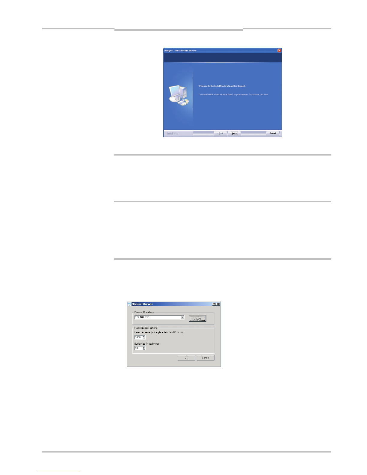
8. Choose Options
Æ Options from the Ranger Studio menu bar.
The following dialog box is displayed:
9. Fill in the Camera IP address, or select it from the menu, and click OK.
If the Ranger’s IP address is missing in the menu, use the Update button.
Updating the menu may take approximately 15 seconds. You also need to have administrator privileges on the PC for the menu to be updated properly.
If you still can not see the Ranger’s IP address, use the iCon Device Configuration utility, which can be launched from the Start menu. Information on using iCon Device
Configuration can be found in Appendix E.
Chapter 2 Operating Instructions
Ranger E/D
12 SICK IVP • Industrial Sensors • www.sickivp.com • All rights reserved 8011731
Installation Guide
10. Click Connect on the toolbar in Ranger Studio.
The status bar at the bottom of the Ranger Studio main window shows the camera
type and version. The same message is also written in the log.
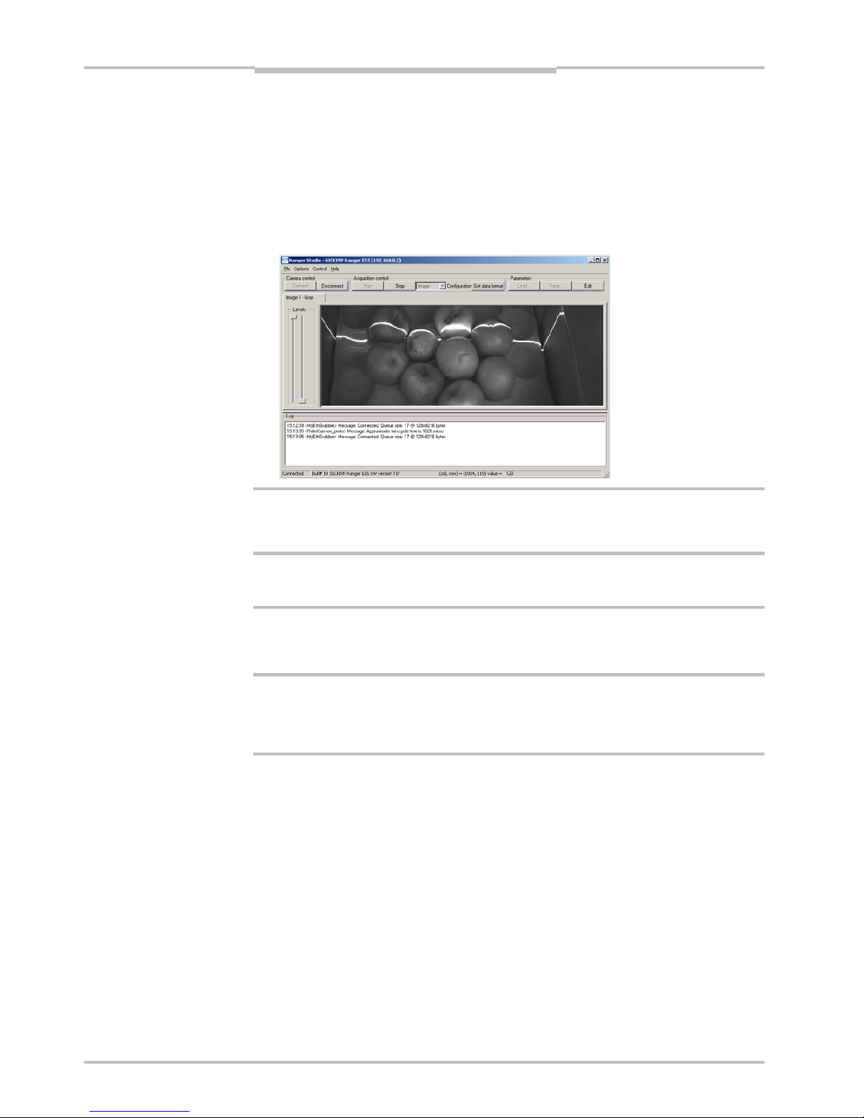
11. Choose Image from the Configuration menu.
The main window contains one visualization tab, but which is still empty.
12. Click Start to start the acquisition.
The visualization tab shows a live 2D view from the Ranger. If an object is present under a laser line, the projected laser line is also seen in the view.
The Image mode is very useful when it comes to adjusting the exposure time and to decide
the region of interest. More information on how to use the visualization window can be
found in Ranger Studio chapter.
13. When you are ready click Stop to stop the acquisition.
14. Click Disconnect to shut down the conection to the Ranger.
2.6 Maintenance
Warning
If the Ranger is used with a laser, the power to the laser must be turned off before any
maintenance is performed. Failure to turn the power off when maintaining the unit may
result in hazardous radiation exposure.
Check screw connections and connectors at regular intervals.
Clean the housing with a soft cloth, dry or dampened with a mild water diluted cleaning
agent without powder additives.
2.7 Service
The Ranger contains no user serviceable parts inside.
In case of unit failure contact SICK IVP or an SICK IVP representative that delivered the
unit for further instructions.
a
 Loading...