

Page 1
WSU/WEU26-3
Single-beam Photoelectric Safety Switch
OPERATING INSTRUCTIONS
en
Page 2

Operating Instructions
WSU/WEU263
This document is protected by the law of copyright, whereby all rights established therein remain with the
company SICK AG. Reproduction of this document or parts of this document is only permissible within the limits
of the legal determination of Copyright Law. Alteration or abridgement of the document is not permitted without
the explicit written approval of the company SICK AG.
2 © SICK AG • Industrial Safety Systems • Germany • All rights reserved 8013338/YTA4/2016-03-24
Subject to change without notice
Page 3

Operating Instructions
WSU/WEU263
Contents
Contents
1 About this document.........................................................................................................5
1.1 Function of this document....................................................................................5
1.2 Target group ..........................................................................................................5
1.3 Scope ..................................................................................................................... 5
1.4 Depth of information............................................................................................. 5
1.5 Abbreviations.........................................................................................................6
1.6 Terminology, symbols used ..................................................................................6
2 On safety.............................................................................................................................7
2.1 Qualified safety personnel.................................................................................... 7
2.2 Applications of the device.....................................................................................7
2.3 Correct use ............................................................................................................8
2.4 General safety notes and protective measures ..................................................8
2.5 Environmental protection .....................................................................................9
2.5.1 Disposal ............................................................................................... 9
2.5.2 Separation of materials ...................................................................... 9
3 Product description.........................................................................................................10
3.1 Special features ..................................................................................................10
3.2 Operating principle of the device .......................................................................10
3.2.1 Scanning range .................................................................................11
3.2.2 Restart interlock................................................................................11
3.2.3 External device monitoring (EDM)....................................................11
3.2.4 Front screen heating.........................................................................11
3.3 Structure and function........................................................................................12
3.4 Application example............................................................................................13
4 Mounting ..........................................................................................................................14
4.1 Preparation for mounting ...................................................................................14
4.1.1 Safety distance for access protection..............................................14
4.1.2 Minimum distance to reflective surfaces ........................................17
4.1.3 Mutual interference of systems in close proximity .........................18
4.2 Mechanical mounting .........................................................................................18
4.2.1 Deflector mirror .................................................................................20
5 Electrical installation......................................................................................................22
5.1 Important information for the installation .........................................................22
5.2 System connection..............................................................................................23
5.2.1 Pin assignment sender .....................................................................23
5.2.2 Tested ................................................................................................23
5.2.3 Pin assignment receiver ...................................................................24
5.3 Arc-suppression...................................................................................................25
5.4 Cross-circuit monitoring......................................................................................25
5.5 Overcurrent protection (fuse) .............................................................................25
8013338/YTA4/2016-03-24 © SICK AG • Industrial Safety Systems • Germany • All rights reserved 3
Subject to change without notice
Page 4

Contents
WSU/WEU263
6 Commissioning................................................................................................................ 26
6.1 Aligning sender and receiver .............................................................................26
6.1.1 Alignment using the diagnostics LEDs ............................................ 26
.1.2 Alignment using the AR60 laser alignment aid ..............................27
6
6.2 Test notes............................................................................................................ 28
6.2.1 Tests before the initial commissioning............................................28
6.2.2 Daily functional checks of the protective device ............................28
6.2.3 Regular inspection of the protective device by qualified
safety personnel ...............................................................................29
7 Care and maintenance ...................................................................................................30
8 Fault diagnosis ................................................................................................................31
8.1 In the event of faults or errors ........................................................................... 31
8.2 SICK support .......................................................................................................31
8.3 Status displays of the diagnostics LEDs ........................................................... 31
9 Technical specifications ................................................................................................ 33
10 Ordering information ...................................................................................................... 36
10.1 Devices................................................................................................................ 36
10.2 Deflector mirror................................................................................................... 36
10.3 Accessories ......................................................................................................... 36
10.4 Dimensional drawings ........................................................................................ 37
Operating Instructions
11 Annex................................................................................................................................ 40
11.1 Compliance with EU directives........................................................................... 40
11.2 Checklist for the manufacturer.......................................................................... 41
11.3 List of tables .......................................................................................................42
11.4 List of illustrations ..............................................................................................42
4 © SICK AG • Industrial Safety Systems • Germany • All rights reserved 8013338/YTA4/2016-03-24
Subject to change without notice
Page 5

Operating Instructions Chapter 1
WSU/WEU263
About this document
1 About this document
lease read this chapter carefully before you work with these operating instructions and
P
the WSU/WEU26@3 single-beam photoelectric safety switches, referred to in the following
as WSU/WEU26@3 devices.
1.1 Function of this document
These operating instructions are designed to address the technical personnel of the
machine manufacturer or the machine operator in regards to safe mounting, installation,
configuration, electrical installation, commissioning, operation and maintenance of the
WSU/WEU26@3 devices.
These operating instructions do not provide instructions for operating machines on which
the WSU/WEU26@3 devices are, or will be, integrated. Information on this is to be found in
the appropriate operating instructions for the machine.
1.2 Target group
These operating instructions are addressed to planning engineers, machine designers and
operators of plants and systems which are to be protected by the WSU/WEU26@3 devices.
They are also addressed to people who integrate the WSU/WEU26@3 devices into a
machine, initialise its use, or who are in charge of servicing and maintaining the device.
1.3 Scope
These operating instructions are original operating instructions.
These operating instructions are only applicable to the WSU/WEU26@3 single-beam
photoelectric safety switch with one of the following entries on the type label in the field
Operating Instructions:
• 8013336
• 8013336/YTA4
This document is part of SICK part number 8013336 (operating instructions
“WSU/WEU26@3 single-beam photoelectric safety switch” in all available languages).
1.4 Depth of information
These operating instructions contain the following information on the WSU/WEU26@3
devices:
• mounting,
• electrical installation,
• commissioning,
• application,
Planning and using protective devices such as the WSU/WEU26@3 devices also require
specific technical skills which are not detailed in this documentation.
When operating the WSU/WEU26@3 devices, the national, local and statutory rules and
regulations must be observed.
General information on accident prevention using opto-electronic protective devices can
be found in the brochure “Guidelines Safe Machinery – Six steps to the safe machine”.
• error diagnosis and troubleshooting,
• part numbers,
• conformity and approval,
• care and maintenance.
8013338/YTA4/2016-03-24 © SICK AG • Industrial Safety Systems • Germany • All rights reserved 5
Subject to change without notice
Page 6

Chapter 1 Operating Instructions
WSU/WEU263
About this document
Note
EDM
ESD
ESPE
LED
OSSD
Recommendation
Note
Red, Yellow,
Green
Take action …
We also refer you to the SICK homepage on the Internet at www.sick.com.
Here you will find information on:
• sample applications,
• these operating instructions in different languages for viewing and printing,
• EU declaration of conformity and other documents.
1.5 Abbreviations
External device monitoring
Electro-static discharge
Electro-sensitive protective equipment
Light Emitting Diode
Output signal switching device
1.6 Terminology, symbols used
Recommendations are designed to give you some assistance in your decision-making
process with respect to a certain function or a technical measure.
Refer to notes for special features of the device.
LED symbols describe the state of a diagnostics LED. Examples:
Red The red LED is illuminated constantly.
Yellow The yellow LED is flashing.
Green The green LED is off.
Instructions for taking action are shown by an arrow. Read carefully and follow the
instructions for action.
WARNING
Warning!
A warning notice indicates an actual or potential risk or health hazard. They are designed
to help you to prevent accidents.
Read carefully and follow the warning notices!
Sender and receiver
In drawings and diagrams, the symbol denotes the sender and the symbol denotes
the receiver.
The term “dangerous state”
The dangerous state (standard term) of the machine is always shown in the drawings and
diagrams of this document as a movement of a machine part. In practical operation, there
may be a number of different dangerous states:
• machine movements,
• electrical conductors,
• visible or invisible radiation,
• a combination of several risks and hazards.
6 © SICK AG • Industrial Safety Systems • Germany • All rights reserved 8013338/YTA4/2016-03-24
Subject to change without notice
Page 7

Operating Instructions Chapter 2
WSU/WEU263
On safety
2 On safety
his chapter deals with your own safety and the safety of the equipment operators.
T
Please read this chapter carefully before working with the WSU/WEU26@3 devices or with
the machine protected by the WSU/WEU26@3 devices.
2.1 Qualified safety personnel
The WSU/WEU26@3 devices must be mounted, commissioned and serviced only by
qualified safety personnel. Qualified safety personnel are defined as persons who
have undergone the appropriate technical training
and
who have been instructed by the responsible machine operator in the operation of the
machine and the current valid safety guidelines
and
who have access to these operating instructions.
WARNING
2.2 Applications of the device
The WSU/WEU26@3 devices are electro-sensitive protective equipment (ESPE), type 4 in
accordance with IEC 61496-1 and IEC 61496-2 and may for this reason be used in
controllers of safety category 4 in accordance with EN ISO 13849, SILCL3 in accordance
with EN 62061 or up to PL e in accordance with EN ISO 13849. The WSU/WEU26@3
devices are used for:
hazardous area protection,
access protection.
The photoelectric switch must be installed such that the hazardous area can only be
reached by interrupting the light path between sender and receiver. It must not be possible
to start the plant/system as long as personnel are within the hazardous area.
The WSU/WEU26-3 devices are intended only for use in industrial environments. When
used in residential areas it can cause radio interferences.
Please refer chapter 3.4 on page 13 for an illustration of the protection mode and an
example application.
Only use the WSU/WEU263 devices as an indirect protective measure!
Opto-electronic protective devices as the WSU/WEU26@ 3 devices cannot provide any
protection against parts thrown out or against radiation. Transparent objects are not
detected.
Depending on the application, mechanical protective devices may be required in addition
to the WSU/WEU26@3 devices.
8013338/YTA4/2016-03-24 © SICK AG • Industrial Safety Systems • Germany • All rights reserved 7
Subject to change without notice
Page 8

Chapter 2 Operating Instructions
WSU/WEU263
On safety
2.3 Correct use
he WSU/WEU26@3 devices may only be used as specified in chapter 2.2 “Applications of
T
the device”. They are only allowed to be used by qualified safety personnel and only on the
machine on which they have been installed and initialised by qualified safety personnel as
per these operating instructions.
All warranty claims against SICK AG are forfeited in the case of any other use, or
alterations being made to the WSU/WEU26@3 devices, even as part of their mounting or
installation.
2.4 General safety notes and protective measures
Safety notes
WARNING
Please observe the following items in order to ensure the correct and safe use of the
WSU/WEU26@3 devices.
• National/international rules and regulations apply to the installation, commissioning,
use and periodic technical inspections of the WSU/WEU26@3 devices, in particular:
– Machinery Directive,
– Work Equipment Directive,
– the work safety regulations/safety rules,
– other relevant safety regulations.
• Manufacturers and operators of the machine on which the WSU/WEU26@3 devices are
used are responsible for obtaining and observing all applicable safety regulations and
rules.
• It is imperative the test notes from page 28 of these operating instructions (“Tests
before the first commissioning”, “Daily functional checks of the protective device”,
“Regular inspection of the protective device by qualified safety personnel”) are followed.
• The tests must be carried out by qualified safety personnel or specially qualified and
authorised personnel and must be recorded and documented to ensure that the tests
can be reconstructed and retraced at any time.
• The operating instructions must be made available to the operator of the machine where
the WSU/WEU26@3 devices are used. The machine operator is to be instructed in the
use of the device by qualified safety personnel and must be instructed to read the
operating instructions.
• The external voltage supply for the devices must be capable of buffering brief mains
voltage failures of 20 ms as specified in EN 60204. Suitable power supplies are
available as accessories from SICK.
• A safety extra-low voltage SELV/PELV must be used to supply power to the
WSU/WEU26@3 devices.
8 © SICK AG • Industrial Safety Systems • Germany • All rights reserved 8013338/YTA4/2016-03-24
Subject to change without notice
Page 9

Operating Instructions Chapter 2
Tab. 1:
Overview on disposal
WSU/WEU263
On safety
2.5 Environmental protection
he WSU/WEU26@3 devices are constructed in such a way that they adversely affect the
T
environment as little as possible. The devices use only a minimum of power and natural
resources.
At work, always act in an environmentally responsible manner. For this reason please note
the following information on disposal.
2.5.1 Disposal
Always dispose of unserviceable or irreparable devices in compliance with local/national
rules and regulations with respect to waste disposal.
Note
We would be pleased to be of assistance on the disposal of this device. Contact your local
SICK representative.
Information on the individual materials in the WSU/WEU26@3 is given in chapter 9
“Technical specifications” from page 33.
2.5.2 Separation of materials
by components
WARNING
Only appropriately trained personnel are allowed to separate materials!
Caution is required when dismantling devices. There is a risk of injuries.
Before you send the devices for appropriate recycling, it is necessary to separate the
different materials in the WSU/WEU26@3 devices.
Separate the housing from the rest of the parts (in particular the circuit board).
Send the separated parts for recycling as appropriate (see Tab. 1).
Components Disposal
Product
Housing
Circuit boards, cable, connector and
electrical connecting pieces
Packaging
Cardboard, paper
Polyethylene packaging
Metal recycling (aluminium)
Electronic recycling
Paper/cardboard recycling
Plastic recycling
8013338/YTA4/2016-03-24 © SICK AG • Industrial Safety Systems • Germany • All rights reserved 9
Subject to change without notice
Page 10
Chapter 3 Operating Instructions
F
ig. 1:
Key data for the
0.5 ... 20 m
Light path between se
nder and receiver
WSU/WEU263
Product description
3 Product description
his chapter provides information on the special features, the operating principle, the
T
structure and the function of the WSU/WEU26@3 devices.
Please read this chapter before mounting, installing and commissioning the
WSU/WEU26@3 devices.
3.1 Special features
• relay outputs
• rugged type of construction
• high operating range up to 70 m
• front screen heating
3.2 Operating principle of the device
The single-beam photoelectric safety switch consists of a WSU26-3 sender unit and a
WEU26-3 receiver. The sender unit WSU26-3 emits a beam of light that is received by the
receiver unit WEU26-3.
WSU/WEU26&3 devices
WSU26-3 WEU26-3
RW
15 ... 70 m
If the light beam is interrupted by an object, a switching command is triggered. The
machine or plant controller that evaluates this message must then bring the dangerous
movement to a halt.
Sender and receiver units are equipped with LEDs for the operational check. Their function
as diagnostic elements is described in chapter 6 “Commissioning”.
The diagnostics LEDs are used for fault diagnosis (see chapter 8 “Fault diagnosis”).
The WSU/WEU26@3 devices are not equipped with an internal restart interlock.
10 © SICK AG • Industrial Safety Systems • Germany • All rights reserved 8013338/YTA4/2016-03-24
Subject to change without notice
Page 11

Operating Instructions Chapter 3
Tab. 2:
Receiver variants
WSU/WEU263
WARNING
Note
Product description
3.2.1 Scanning range
Use the receiver with the permitted operating range to suit the length of the light path
between the sender and receiver!
• If the operating range is too low, the single-beam photoelectric safety switch may not
switch to green.
• If the operating range is too large, the single-beam photoelectric safety switch may
malfunction due to reflections. This would mean that the operator is at risk.
Two receiver with different scanning ranges are available:
Receiver Operating range
WEU26-3-103A00 0.5 ... 20 m
WEU26-3-203A00 15 ... 70 m
3.2.2 Restart interlock
The WSU/WEU26@3 devices do not have an internal restart interlock. It is only possible to
implement a restart interlock for the machine externally. During this process the
WSU/WEU26@3 devices have no control over the restart.
A restart interlock prevents the machine starting again after an error or an interruption of
the light path.
WARNING
Note
WARNING
Always operate the application with restart interlock!
Ensure an external restart interlock is always activated on the machine. The
WSU/WEU26@3 devices are unable to verify if the external restart interlock of the machine
is operable. If you deactivate the external restart interlock, the operator of the machine will
be at acute risk of injury.
3.2.3 External device monitoring (EDM)
The WSU/WEU26@3 devices do not have any feature for monitoring the downstream
contactors. External device monitoring on the downstream contactors is only possible with
an external circuit. You will find additional explanations on the connection of downstream
contactors in chapter 5.2 “System connection”.
An EDM checks if the downstream contactors actually de-energize when the protective
device is tripped.
3.2.4 Front screen heating
Sender and receiver have front screen heating. The front screen heating counteracts the
formation of droplets, mist, frost and ice.
Ensure the optical properties of the front screen are not changed by the formation of
droplets, mist, frost or ice, otherwise there will be a hazard for the operator.
8013338/YTA4/2016-03-24 © SICK AG • Industrial Safety Systems • Germany • All rights reserved 11
Subject to change without notice
Page 12
Chapter 3 Operating Instructions
Fig. 2:
Diagnostics LEDs
Tab. 3:
Diagnostics LEDs
Fig. 3:
Diagnostics LEDs
Tab. 4:
Diagnostics LEDs
WSU/WEU263
Product description
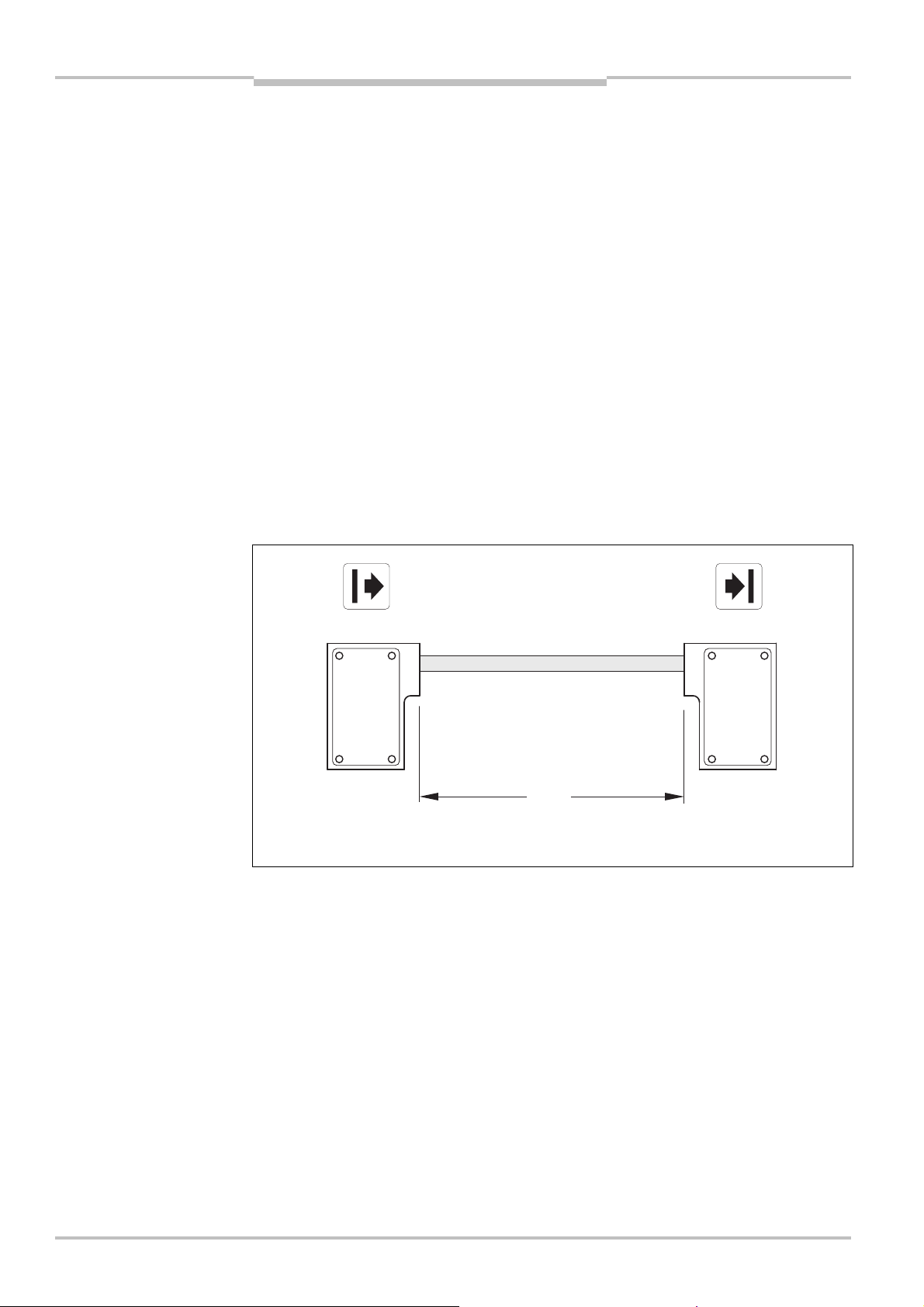
3.3 Structure and function
he WSU/WEU26@3 devices are equipped with diagnostics LEDs:
T
Diagnostics LEDs of the sender
WSU26-3
WSU26-3
Yellow Red
WSU26-3
WEU26-3
WEU26-3
Display
Yellow Red
Meaning
Device on, test inactive
Device on, test active, test contacts open
Diagnostics LEDs of the receiver
WEU26-3
Green Yellow Red
Display
Green Yellow Red
Output signal switching devices on, light path
Meaning
unoccupied
12 © SICK AG • Industrial Safety Systems • Germany • All rights reserved 8013338/YTA4/2016-03-24
Output signal switching devices off, light path
interrupted or inadequate alignment or device
not yet ready after switch on (see technical
specifications)
Output signal switching devices on, light path
unoccupied, weak signal
Output signal switching devices off, light path
interrupted or inadequate alignment. Prior to the
complete interruption of the light path the signal
was weak.
Subject to change without notice
Page 13
Operating Instructions Chapter 3
Fig. 4:
Access guarding with
Access guarding with
M
echanical protection
Direction of entry
into the hazardous
WSU/WEU263
Product description
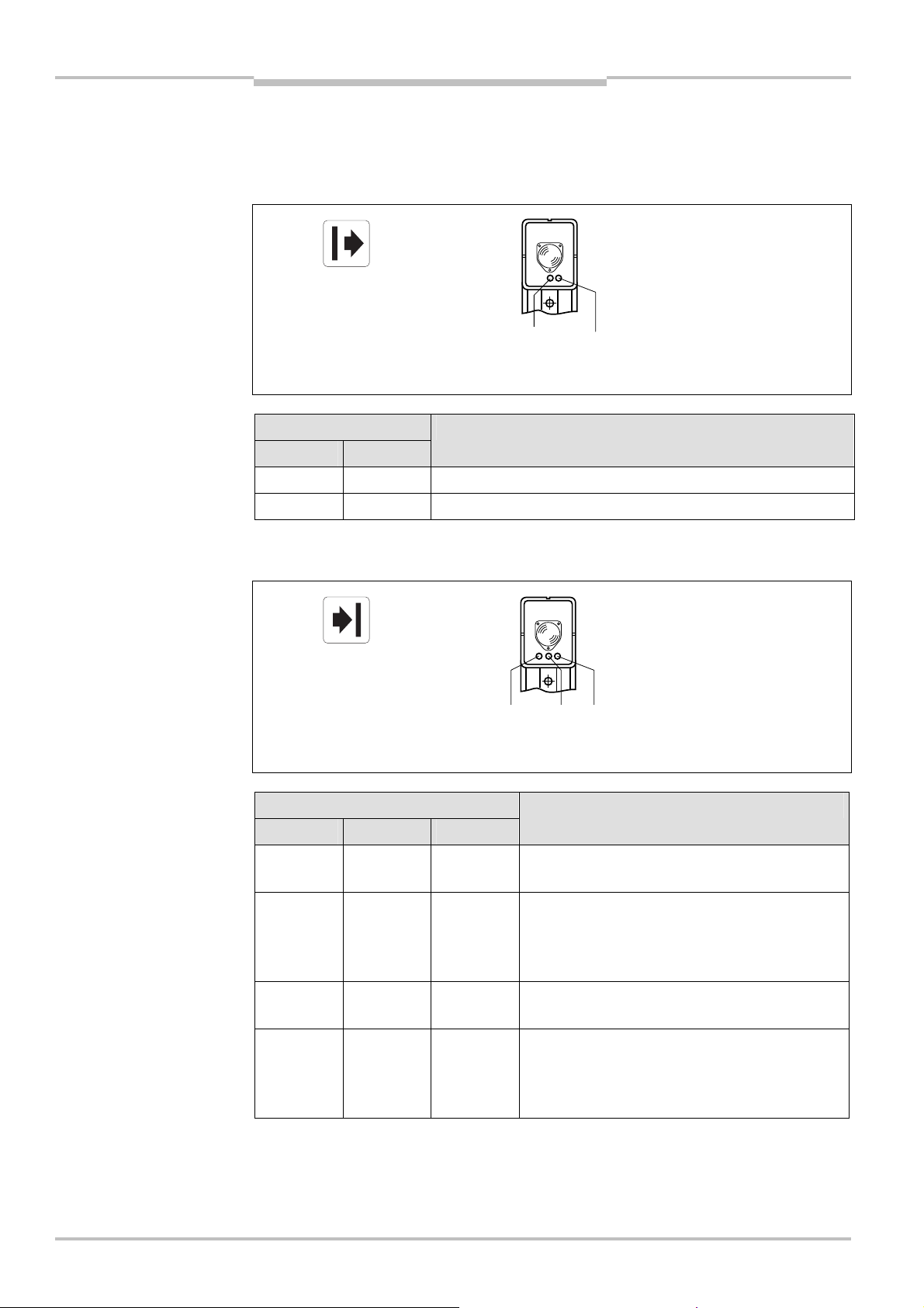
3.4 Application example
he WSU/WEU26@3 devices are used as access protection for hazardous areas on
T
machines or systems (Fig. 4). The devices are permanently mounted in the access area
with the necessary safety distance from the nearest hazardous point. If the light beam is
interrupted by an object, a switching command is triggered. The machine or plant
controller that evaluates this message must then bring the dangerous movement to a halt.
WSU/WEU26&3
WSU/WEU26@3
Hazardous point
S
area
8013338/YTA4/2016-03-24 © SICK AG • Industrial Safety Systems • Germany • All rights reserved 13
Subject to change without notice
Page 14

Chapter 4 Operating Instructions
WSU/WEU263
Mounting
4 Mounting
his chapter describes the preparation and completion of the installation of the
T
WSU/WEU26@3 devices:
• calculating the necessary safety distance,
• calculating the distance from reflective surfaces,
mounting the device.
•
The following steps are necessary after mounting:
• complete the electrical connections (chapter 5),
• alignment of senders and receivers (chapter 6.1),
• testing the installation (chapter 6.2).
No protective function without sufficient safety distance!
WARNING
The reliable protective effect of the single-beam photoelectric safety switches depends on
the WSU/WEU26@3 devices being mounted with the correct safety distance from the
hazardous point.
4.1 Preparation for mounting
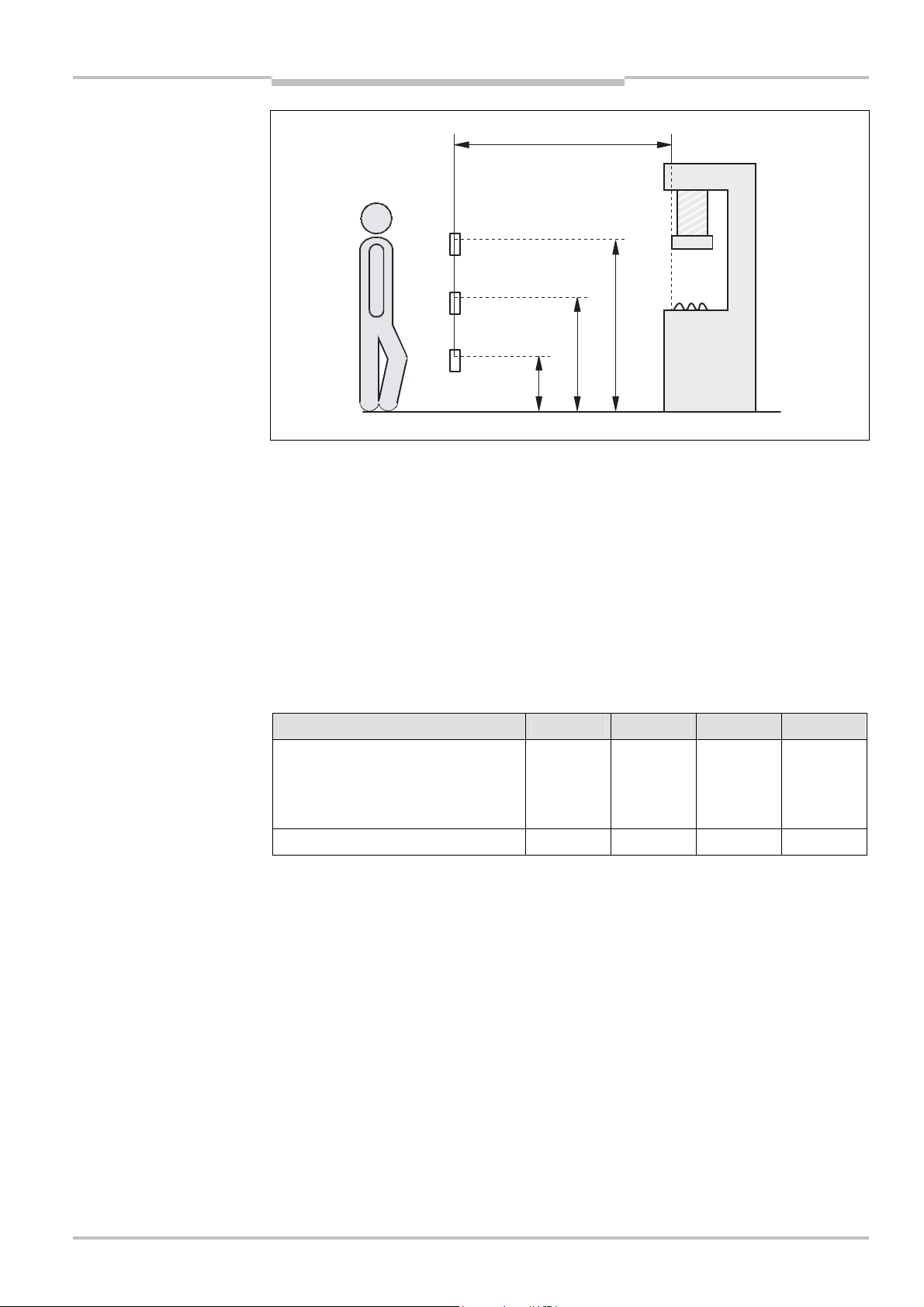
4.1.1 Safety distance for access protection
A safety distance must be maintained between the protective field and the hazardous
point. This safety distance ensures that the hazardous point can only be reached after the
dangerous state of the machine has been completely stopped.
The safety distance as per EN ISO 13855 and EN ISO 13857 depends on:
• stopping/run-down time of the machine or system (The stopping/run-down time is
shown in the machine documentation or must be determined by taking a
measurement.),
• response time of the entire protective device,
• reach or approach speed,
• number of beams/beam separation.
Under the authority of OSHA and ANSI the safety distance as specified by
ANSI B11.19 (Annex D) E.4.2.3.3.5 and Code of Federal Regulations, Volume 29,
Part 1910.217 ... (h) (9) (v) depends on:
• stopping/run-down time of the machine or system (The stopping/run-down time is
shown in the machine documentation or must be determined by taking a
measurement.),
• response time of the entire protective device,
• reach or approach speed,
• other parameters that are stipulated by the standard depending on the application.
14 © SICK AG • Industrial Safety Systems • Germany • All rights reserved 8013338/YTA4/2016-03-24
Subject to change without notice
Page 15
Operating Instructions Chapter 4
Fig. 5:
Safety distance S to
Tab. 5:
Height of the beams
Hazardous
WSU/WEU263
Mounting
the light beam
Note
Safety distance S (D
)
S
1.100
oint
p
700
WSU/WEU26@3
300
How to calculate the safety distance S according to EN ISO 13855 and EN ISO 13857:
The following calculation shows an example calculation of the safety distance. Depending
on the application and the ambient conditions, a different calculation may be necessary.
First, calculate S using the following formula:
S = K × T + C [mm]
Where ...
T = Stopping/run-down time of the machine + response time of the WSU/WEU26@3
devices after light path interruption [s]
S = Safety distance [mm]
K = Approach speed 1.6 [m/s]
C = Depending on the number of beams (1, 2, 3 or 4), see Tab. 5
above the floor
Number of beams 1 2 3 4
Height of the beams above the floor
[mm]
750 400
900
300
700
1,100
300
600
900
1,200
C 1,200 850 850 850
Example:
Access guarding with two beams C = 850 mm
Stopping/run-down time of the machine = 290 ms
Response time after light path interruption = 22 ms
Approach speed = 1.6 m/s
T = 290 ms + 22 ms = 312 ms = 0.31 s
S = 1,600 × 0.31 + 850 = 1,346 mm
8013338/YTA4/2016-03-24 © SICK AG • Industrial Safety Systems • Germany • All rights reserved 15
Subject to change without notice
Page 16

Chapter 4 Operating Instructions
WSU/WEU263
Note
Note
Mounting
How to calculate the safety distance DSaccording to ANSI B11.19 (Annex D)
E.4.2.3.3.5 and Code of Federal Regulations, Volume 29, Part 1910.217 … (h) (9) (v):
he following calculation shows an example calculation of the safety distance. Depending
T
on the application and the ambient conditions, a different calculation may be necessary.
First, calculate D
D
= HS× (TS+ TC+ Tr+ Tbm) + Dpf
S
Where ...
D
= The minimum distance in inches (or millimetres) from the hazardous point to the
S
protective device
= A parameter in inches/second or millimetres/second, derived from data on
H
S
approach speeds of the body or parts of the body. Often 63 inches/second is
used for H
T
= Stopping/run down time of the machine tool measured at the final control
S
element
= Stopping/run-down time of the control system
T
C
T
= Response time of the entire protective device after light path interruption
r
T
= Additional response time allowed for brake monitor to compensate for wear
m
b
Any additional response times must be accounted for in this calculation.
D
= An additional distance added to the overall safety distance required. This value is
pf
based on intrusion toward the hazardous point prior to actuation of the electrosensitive protective equipment (ESPE). For applications that can be reached over,
the value D
arms or the detectable object size is greater than 63 mm, the value D
using the following formula:
s
.
S
= 1.2 m. For beam arrangements that permit reaching in with the
f
p
f
p
= 0.9 m.
WARNING
WARNING
Maintain the safety distance!
The WSU/WEU26@3 devices are to be fitted such that when the light beam is interrupted,
the hazardous point is only reached when the dangerous state is no longer present.
Risk of failure to detect!
Persons who are in the hazardous area but not in the light path between sender and
receiver are not detected by the WSU/WEU26@3 devices. It is therefore to be ensured that
the hazardous area is fully visible and any dangerous state can only be initiated if there
are no personnel in the hazardous area.
The WSU/WEU26@3 devices are not allowed to be used for hand and finger protection.
The applicable legal and official regulations apply to the use and mounting of the
protective device. These regulations vary depending on the application.
16 © SICK AG • Industrial Safety Systems • Germany • All rights reserved 8013338/YTA4/2016-03-24
Subject to change without notice
Page 17
Operating Instructions Chapter 4
Fig. 6:
Minimum distance to
Fig. 7:
Graph, minimum
Tab. 6:
Formula for the
Reflective surface
Field of view
Minimum
Distance D sender
–
receiver
WSU/WEU263
reflective surfaces
Mounting
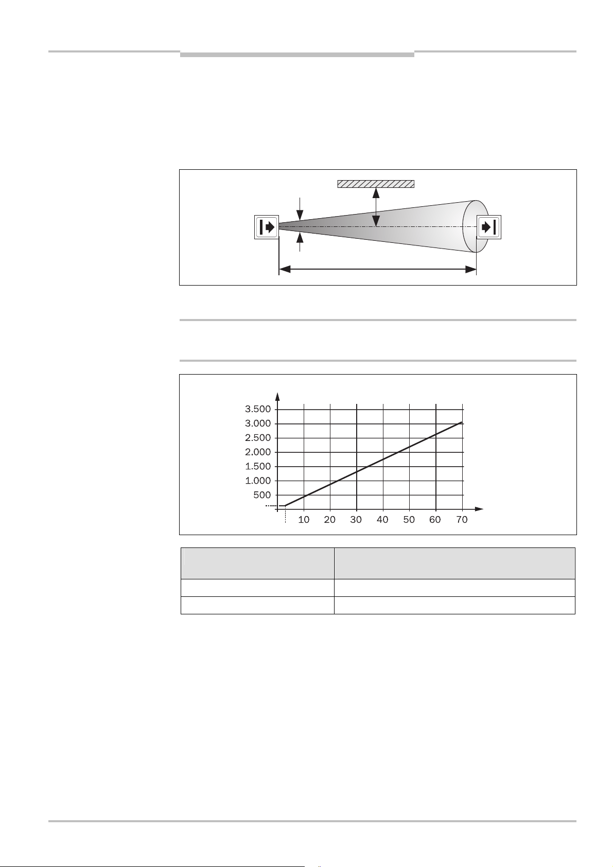
4.1.2 Minimum distance to reflective surfaces
The light beams from the sender may be deflected by reflective surfaces. This can result in
failure to identify the object.
Therefore all reflective surfaces and objects (e.g. material bins) must be a minimum
distance a from the light path between sender and receiver of the WSU/WEU26@ 3 devices.
The minimum distance a depends on the distance D between sender and receiver.
distance a
Note
WARNING
distance from reflective
surfaces
calculation of the minimum
distance to reflective
surfaces
Sender and receiver optics have the same field of view.
The minimum distances to reflective surfaces only apply when the light path is clear. On
the usage of transparent guard windows, these values may change.
a [mm]
131
3
Distance D [m] sender – receiver Calculation of the minimum distance a
from reflective surfaces
D Q 3 m a [mm] = 131
D [m]
8013338/YTA4/2016-03-24 © SICK AG • Industrial Safety Systems • Germany • All rights reserved 17
Subject to change without notice
D > 3 m a [mm] = tan (2.5°) x 1,000 x D [m] = 43.66 x D [m]
Page 18
Chapter 4 Operating Instructions
Fig. 8:
Mounting two
WSU/WEU263
Mounting
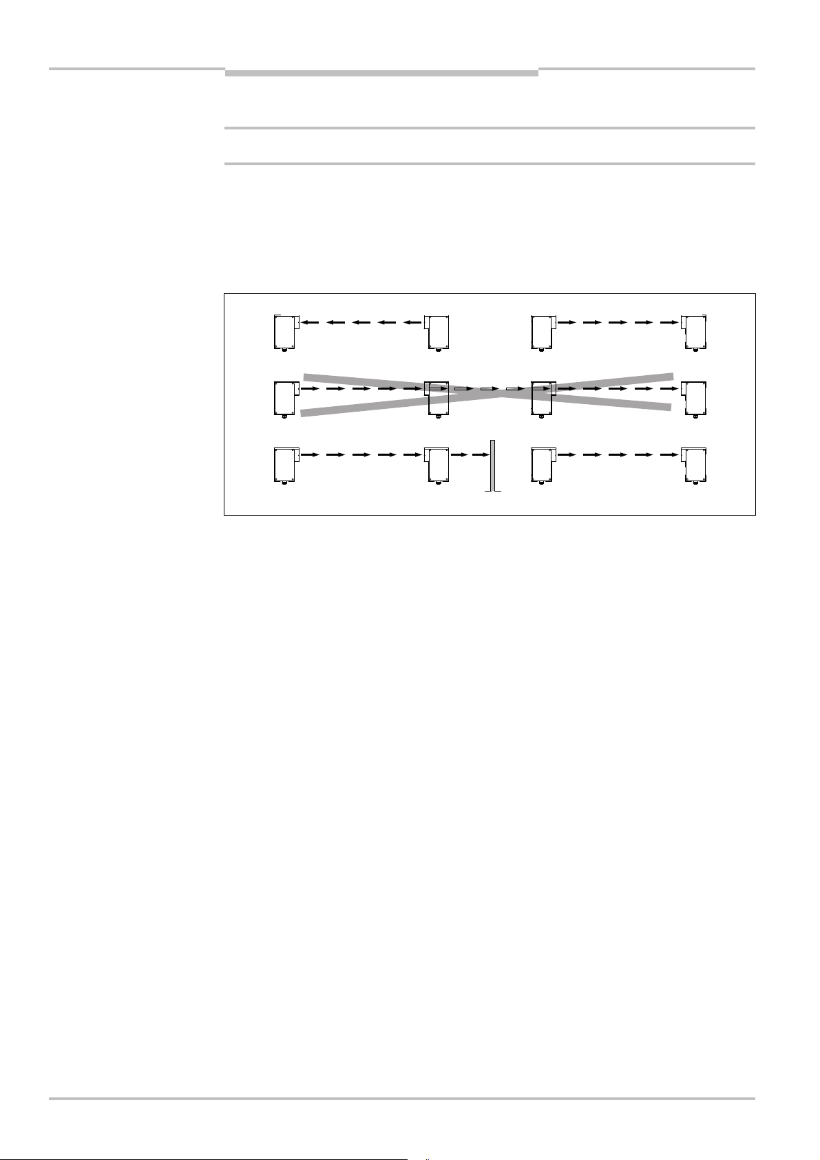
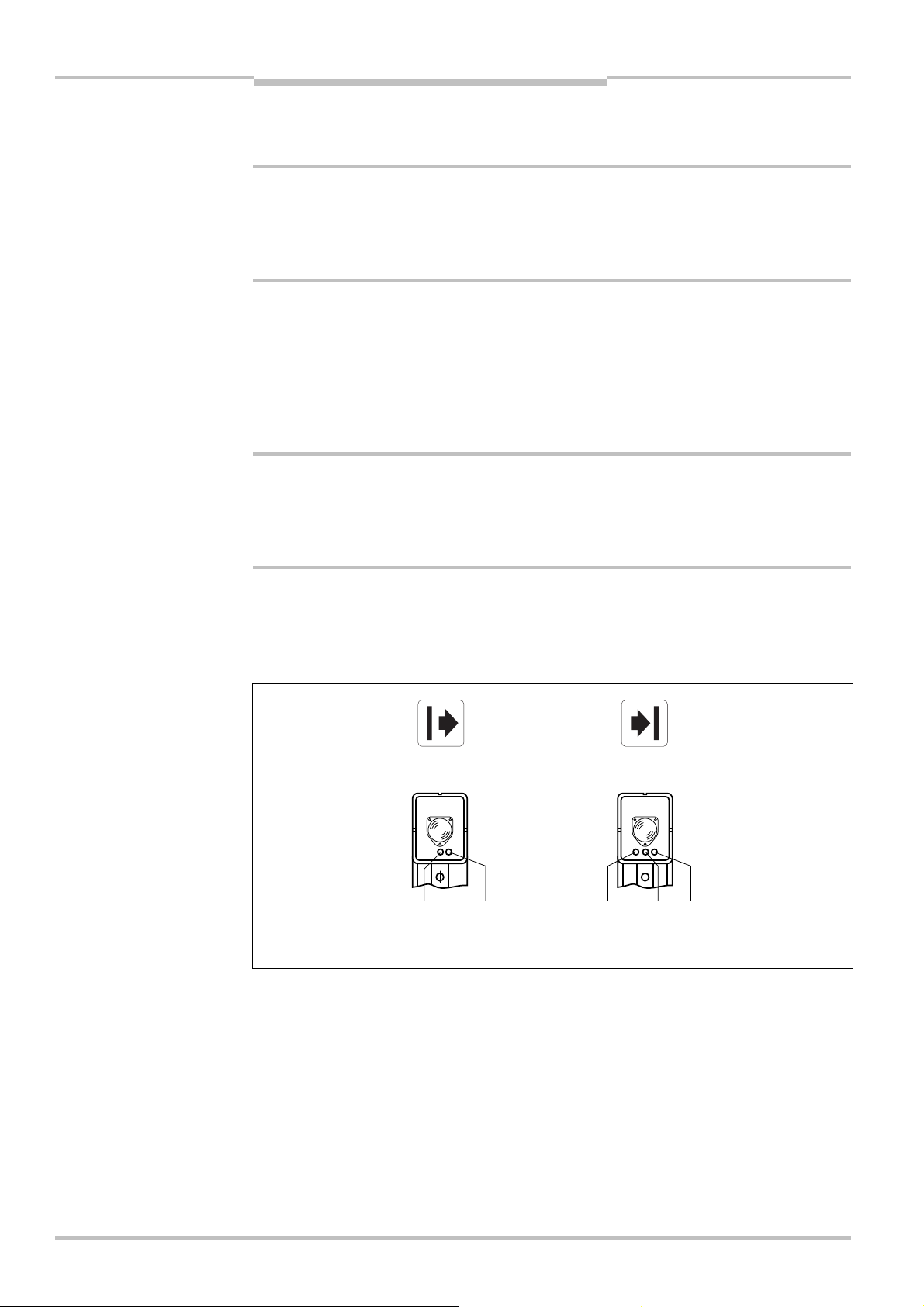
4.1.3 Mutual interference of systems in close proximity
Prevent the mutual interference of systems mounted in close proximity!
WARNING
WSU/WEU26&3 devices in
series
If several WSU/WEU26@3 devices operate in close physical proximity, the sender beams
from one device may interfere with the receiver for another device such that the protective
function of the different WSU/WEU26@3 devices is no longer ensured and there is a hazard
for the operator. You must avoid such mounting scenarios or take appropriate measures,
e.g. by mounting non-reflective sight protection walls or by reversing the transmission
direction of a device.
WEU
WSU WSU
WEU
Note
WSU
WSU
WEU
WEU
WSU
WSU
WEU
WEU
4.2 Mechanical mounting
WSU26-3 and WEU26-3 are to be mounted to suit the local conditions on one of the sides
of their housing or using the mounting bracket. The mounting bracket significantly eases
alignment. The device can be operated in any position. WSU26-3 and WEU26-3 are,
however, to be mounted such that the axis of the beam emitted by the WSU26-3 is always
aligned with the axis of the WEU26-3 optics (alignment sight, see Fig. 18, page 27).
The mounting brackets are to be attached such that all fixing screws are easily accessibly
for alignment. Fig. 9 shows examples. The devices are to be attached such that it is
possible to align with the related device opposite using the alignment sight.
18 © SICK AG • Industrial Safety Systems • Germany • All rights reserved 8013338/YTA4/2016-03-24
Subject to change without notice
Page 19

Operating Instructions Chapter 4
Fig. 9:
Mounting possibilities
Mounting bracket
WSU/WEU263
using mounting brackets
Mounting
8013338/YTA4/2016-03-24 © SICK AG • Industrial Safety Systems • Germany • All rights reserved 19
Subject to change without notice
Part number 2007900
Page 20

Chapter 4 Operating Instructions
Tab. 7:
Reduction in the
Fig. 10:
Hazardous area
Deflector mirror
Deflector mirror
Deflector mirror
Mirror deflection
Safety distance
Hazardous area
Machine
Machine
Hazardous area
WSU/WEU263
Mounting
4.2.1 Deflector mirror
With the WSU/WEU26@3 and deflector mirrors, access protection on several sides can be
realised (Fig. 10).
Note
The usage of deflector mirrors reduces the effective scanning range of the system
WSU/WEU26@3 as specified in Tab. 7.
Note
The usage of mirrors (Fig. 11) requires very precise alignment. It is recommended to use
the AR60 laser alignment aid. The AR60 alignment aid is available as an accessory (Tab.
17, page 36).
scanning range on the usage
of deflector mirrors with
= 90°
protected on several sides
Number of mirrors WEU26-3 with short scanning range WEU26-3 with long scanning range
1 0.5 ... 18 m 14.2 ... 63 m
2 0.5 ... 16 m 13.5 ... 56 m
3 0.5 ... 14.3 m 12.8 ... 50 m
4 0.5 ... 12.8 m 12.2 ... 45 m
20 © SICK AG • Industrial Safety Systems • Germany • All rights reserved 8013338/YTA4/2016-03-24
possible
too short
Machine
Subject to change without notice
Page 21
Operating Instructions Chapter 4
Fig. 11:
Two-beam protection
Tab. 8:
Distances of the
Fig. 12:
Incorrect alignment
Fig. 13:
Correct alignment of
D
eflector mirror
Deflector mirror
Distance deflector mirror
–
WSU/WEU26
-
3
Deflector mirror
Deflector mirror
Field of view 5°
Fie
ld of view 5°
Deflector mirror
Deflector mirror
WSU/WEU263
with one system
WSU/WEU26&3
Mounting
90˚
W
EU
deflector mirrors
of sender and receiver
Note
90˚
WSU
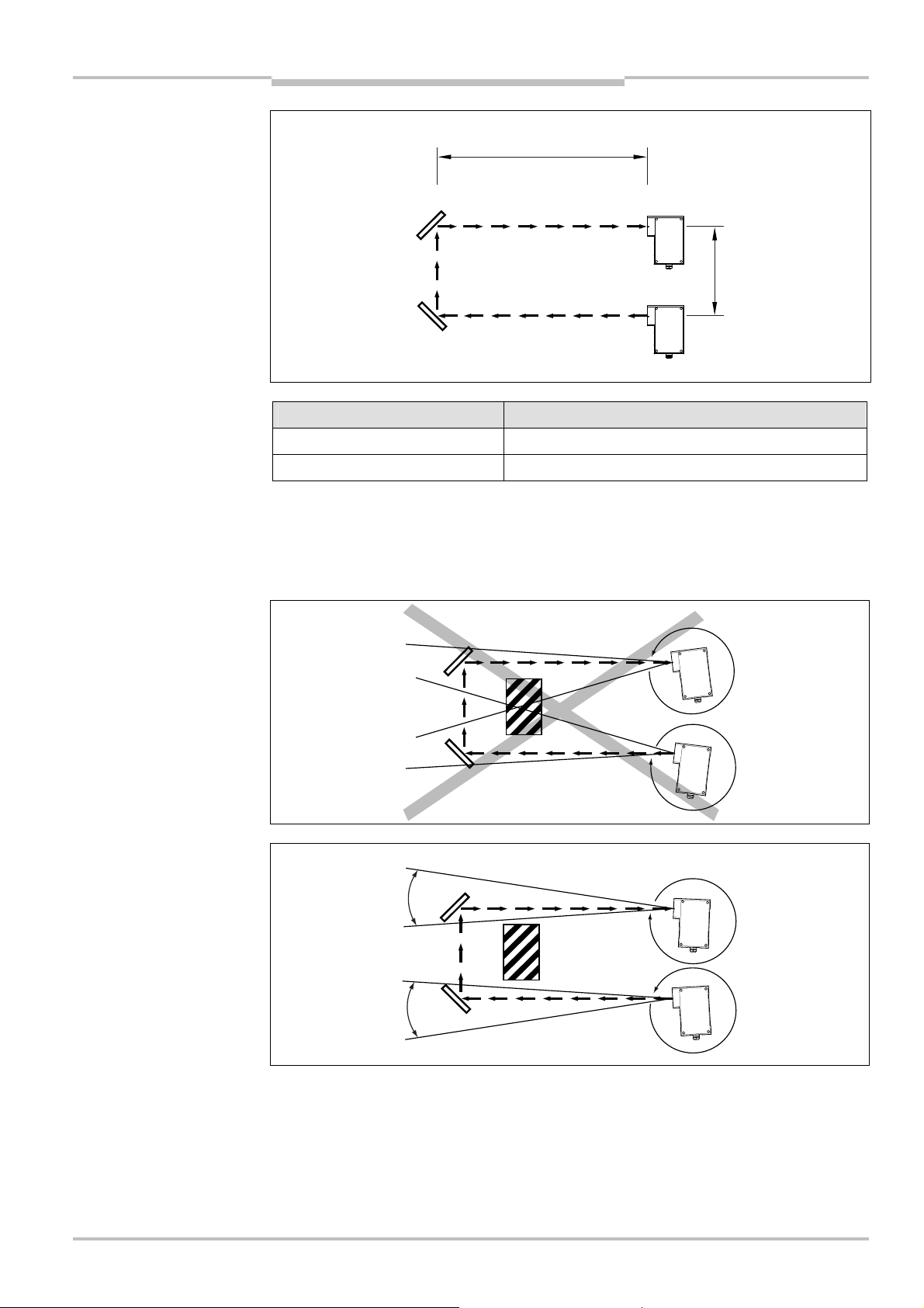
WEU26-3 receiver Distance deflector mirror – WSU/WEU26-3
500 mm
Low scanning range 0.5 ... 7.5 m
High scanning range > 7.5 m
If there are reflective surfaces in the area of the light path between the sender and
receiver or such surfaces may occur, the alignment of the system must be adjusted:
Sender and receiver must always be aligned such that there are no reflecting surfaces in
the area of the field of view (see Fig. 13).
90˚
Reflective surface
WEU
90˚
WSU
sender and receiver
8013338/YTA4/2016-03-24 © SICK AG • Industrial Safety Systems • Germany • All rights reserved 21
Subject to change without notice
90˚
90˚
WEU
Reflective surface
WSU
Page 22

Chapter 5 Operating Instructions
WSU/WEU263
Electrical installation
5 Electrical installation
5.1 Important information for the installation
Switch the entire machine/system off line!
WARNING
The machine/system could inadvertently start up while you are connecting the devices.
Ensure that the entire machine/system is disconnected during the electrical installation.
Notes:
• The WSU/WEU26@3 single-beam photoelectric safety switch meets the interference
suppression requirements (EMC) for industrial use (interference suppression class A).
When used in residential areas it can cause interference.
• A safety extra-low voltage SELV/PELV must be used to supply power to the
WSU/WEU26@3 devices.
• The external voltage supply must bridge a brief mains failure of 20 ms (EN 60204).
Suitable power supplies are available as accessories from SICK.
• Prior to opening the cover (see chapter 10.4 “Dimensional drawings”) all cables for the
supply voltage and the relay connections must be electrically isolated.
• Only open the device with appropriate protection against ESD, i.e. pay attention to
earthing. In the device only touch the connection terminals, not the other parts of the
electronics. All work on the open device is only allowed to be undertaken by qualified
safety personnel.
• If the cover is open, the device does not provide any protective function.
• The connecting cables must be laid directly to the terminal strip.
• After mounting, the firm seating of the connecting cables in the connection terminals
must be checked.
• Observe torque figure for the protective conductor connection (“PE”) (see chapter 5.2
“System connection”, Tab. 9/Tab. 10, Fig. 14/Fig. 15).
• On the installation of another PG connector, it is necessary to comply with the torque
data for the PG connector (see chapter 10.4 “Dimensional drawings”).
• Prior to screwing in place the cover, the seal must be checked for contamination and
damage. Fasten the cover to the related torque (see chapter 10.4 “Dimensional
drawings”).
• After opening the cover, the complete commissioning function test must be performed
(see chapter 6 “Commissioning”).
22 © SICK AG • Industrial Safety Systems • Germany • All rights reserved 8013338/YTA4/2016-03-24
Subject to change without notice
Page 23

Operating Instructions Chapter 5
Tab. 9:
Assignment of the
Fig. 14:
Assignment of the
WSU/WEU263
Electrical installation
5.2 System connection
5.2.1 Pin assignment sender
sensor contacts, sender
WSU26-3
sensor contacts, sender
WSU26-3
Note
Note
Pin Designation
1/2 Voltage supply 24 V DC
3 Ground 0 V
10
11
PE Protective earth
The torque for the PE connection is 2.0 ± 0.5 Nm.
Connect the contacts on the WSU26-3 only to circuits that comply with the requirements
for safety extra-low voltage (SELV/PELV).
5.2.2 Tested
Test contacts
PE
1/2
+ 24 V
3 10 11
0 V
Note
WARNING
The test makes it possible to check the loads connected. For this purpose the electrical
connection between test contacts 10 and 11 on the WSU26-3 is interrupted for a certain
amount of time (see chapter 9 “Technical specifications”). As a result the sender does not
emit a beam of light and simulates an interruption to the light path.
The test must be performed by the machine controller during the unhazardous phase (e.g.
an unhazardous movement). If the test is not successful, the machine must receive a shut
down signal from the machine controller.
To operate the WSU/WEU26@3 devices without testing, a wire jumper must be connected
between the test contacts 10 and 11 on the WSU26-3.
Use test function for the purpose described!
The test input is only allowed to be used in the manner described.
8013338/YTA4/2016-03-24 © SICK AG • Industrial Safety Systems • Germany • All rights reserved 23
Subject to change without notice
Page 24

Chapter 5 Operating Instructions
Tab. 10:
Assignment of the
Fig. 15:
Assignment of the
Electrical installation
WSU/WEU263
5.2.3 Pin assignment receiver
sensor contacts, receiver
WEU26-3
Note
sensor contacts, connection
diagram WEU26-3 on UE43
Pin Designation
1/2 Voltage supply 24 V DC
3 Ground 0 V
4
Safety relay, normally open contact
5
6
Safety relay 1/2, normally closed contacts connected in parallel internally
7
8
Safety relay 2, normally open contact
9
PE Protective earth
Both normally open contacts are to be used for safety-related functions. In a subsequent
dual-channel circuit the two normally open outputs are to be connected to a safety
controller with a suitable level of safety (see Fig. 15).
The normally closed contacts are not allowed to be used for safety-related functions.
If the downstream logic is realised using discrete contactors, they must be positively
guided and externally monitored. The monitoring cannot be provided by the WEU26-3.
The torque for the PE connection is 2.0 ± 0.5 Nm.
+ 24 V
0 V
PE
32/1
A1
UE43-2MF2D2
A2
4
S1
5
S11
+
+
S33 S34 S35
1K
2K
76
S12 S31 S21 S22 13 23 31
CH1+ CH2+
RESET
98
2K2
K
3K3
K
1K 2K
1K
2K
1K
2K
+ VE/L
322414
– VE/N
24 © SICK AG • Industrial Safety Systems • Germany • All rights reserved 8013338/YTA4/2016-03-24
Note
The cross-circuit monitoring on the connecting cables between the normally open contacts
4 and 5 or 8 and 9 on the WEU26-3 is provided by the safety controller UE43.
Subject to change without notice
Page 25

Operating Instructions Chapter 5
Fig. 16:
Circuit for an
Tab. 11:
Examples for arc
-
Supply
Contact in the
Consumer
R
WSU/WEU263
Electrical installation
5.3 Arc-suppression
n case of an inductive load: Use arc-suppression elements!
I
WARNING
inductive load
Suitable arc-suppressors must be connected in parallel with the inductance. Connection in
parallel with the output contact is not permitted. Please also note that the selection of the
suppressors can increase the total switch off times.
uppression diodes should not be used as arc-suppressors, as they considerably increase
S
the switch off time. RC elements are more suitable than varistors.
WEU26-3
suppressors
WARNING
voltage
Supply voltage Part No. R C
115 ... 230 V 6001224 220 U 0.22 VF
24 V 6001225 100 U 2.2 VF
Design: encapsulated in plastic; Connection wires NYAF Ø 0.5 with cable lug; Mounting
using adhesive film or cable tie.
C
5.4 Cross-circuit monitoring
The cables for the relay contacts are not monitored for cross-circuits by the WEU26-3.
Suitable measures
Take suitable measures for cross-circuit monitoring.
These can be:
• laying cables from the WEU26-3 to the loads protected against cross-circuits,
• screening output cables separately and connecting screen to 0 V,
• integration of the two normally open contacts at different voltage levels.
8013338/YTA4/2016-03-24 © SICK AG • Industrial Safety Systems • Germany • All rights reserved 25
Subject to change without notice
5.5 Overcurrent protection (fuse)
A fuse is to be installed in the control circuit with a rating to suit the maximum current on
the output relay.
Page 26
Chapter 6 Operating Instructions
Fig. 17:
WSU26
-
3 sender unit
WSU/WEU263
Commissioning
6 Commissioning
ommissioning requires a thorough check by qualified safety personnel!
C
WARNING
WARNING
Before you operate a system protected by the WSU/WEU26@3 devices for the first time,
make sure that the system is first checked and released by qualified safety personnel.
Please read the notes in chapter 2 “On safety”.
The device is switched on by applying the supply voltage to the sender and receiver unit.
After max. 10 s the WSU/WEU26@3 devices are ready for operation.
6.1 Aligning sender and receiver
After all parts have been mounted and connected, the related sender and receiver must
be aligned in relation to each other.
Secure the plant/system. No dangerous movement possible!
Ensure that the dangerous state of the machine is (and remains) switched off! During the
alignment process, the outputs of the WSU/WEU26@3 devices are not allowed to have any
effect on the machine.
and WEU26-3 receiver unit
6.1.1 Alignment using the diagnostics LEDs
Switch on power supply. The yellow diagnostics LED of the WSU26-3 must light up.
Align devices such that the green diagnostics LED on the WEU26-3 illuminates.
WSU26-3 WEU26-3
Yellow Red
For optimal alignment the sender and receiver, the boundaries are to be determined by
pivoting the sender unit and receiver unit horizontally and vertically. On leaving the related
optical area, the yellow diagnostics LED on the WEU26-3 starts to illuminate. Then fasten
sender and receiver in the middle of the optical area determined.
Green Yellow Red
26 © SICK AG • Industrial Safety Systems • Germany • All rights reserved 8013338/YTA4/2016-03-24
Subject to change without notice
Page 27
Operating Instructions Chapter 6
F
ig. 18:
Mounting the laser
Fixing screw
Adapter for
WSU26@3 sen
der
WEU26@3 receiver
Alignment sight
Alignment aid AR60
WSU/WEU263
Commissioning
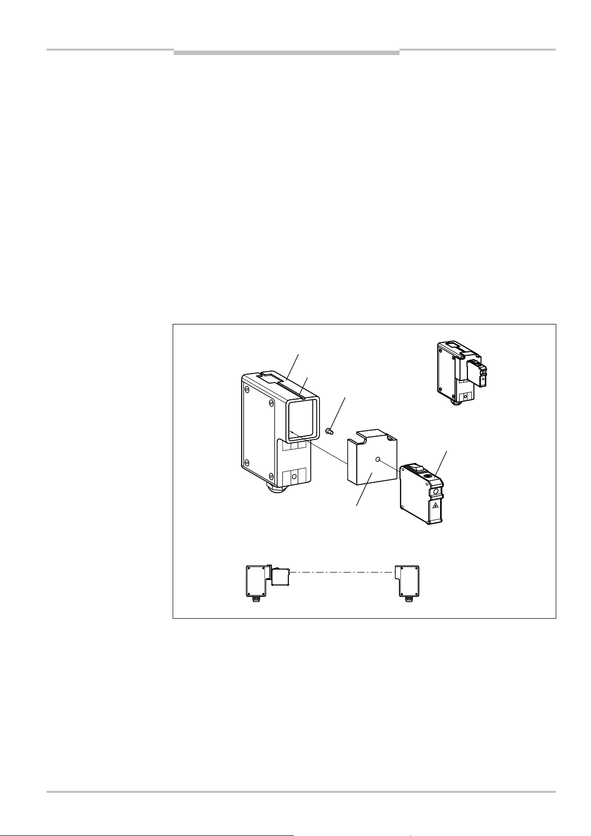
6.1.2 Alignment using the AR60 laser alignment aid
At large scanning ranges or in case of the usage of deflector mirrors, the laser alignment
aid AR60 significantly simplifies alignment. The AR60 alignment aid is available as an
ccessory (Tab. 17, page 36).
a
Screw the adapter to the AR60,
mount the AR60 in front of the sender (clamp),
switch on AR60,
attach a piece of white cardboard or with cardboard reflective tape to the receiver (beam
array is easier to detect),
align sender such that the laser beam array is incident on the middle of the receiver
optics,
fasten sender in this position,
switch off AR60,
remove AR60,
repeat the process starting from the receiver,
switch on sensors.
alignment aid AR60
WSU/WEU26@3
M4 × 10
WSU/WEU26@3
8013338/YTA4/2016-03-24 © SICK AG • Industrial Safety Systems • Germany • All rights reserved 27
Subject to change without notice
Page 28

Chapter 6 Operating Instructions
WSU/WEU263
Commissioning
6.2 Test notes
6.2.1 Tests before the initial commissioning
Check the protective device as described below and in accordance with the applicable
standards and regulations.
To ensure the correct function, check as described in chapter 6.2.2 “Daily functional
checks of the protective device”.
Number of sender and receiver must match, the distance between them must comply
with the operating range stated in the technical specifications.
It must only be possible to access the hazardous area through the light path between
sender and receiver.
It must not be possible to climb over, to crawl beneath or to circumnavigate the
protective device.
Additionally, check the effectiveness of the protective device mounted to the machine,
using all selectable operating modes as specified in the checklist (see chapter 11.2
“Checklist for the manufacturer”). Use this checklist as a reference before
commissioning the system for the first time.
Ensure that the operating personnel of the machine protected by the WSU/WEU26@3
devices are correctly instructed by qualified safety personnel before being allowed to
operate the machine. Instructing the operating personnel is the responsibility of the
machine owner.
6.2.2 Daily functional checks of the protective device
The effectiveness of the protective device must be checked daily or prior to the start of
work by a specialist or by authorised personnel, using the correct test rod.
Testing the light path between sender and receiver:
Completely cover each light beam with a test rod that is not transparent to light (at
least 30 mm diameter) at the following positions:
• immediately in front of the sender,
• in the middle between sender and receiver (or between the deflector mirrors),
• immediately in front of the receiver,
• on the use of deflector mirrors, immediately before and after the deflection.
This must produce the following result:
• The red diagnostics LED must illuminate on the receiver for the related single-beam
photoelectric safety switch
and
• as long as the light beam is interrupted, it must not be possible to initiate the
dangerous state.
Do not operate the machine if during the test the green diagnostics LED on the receiver
is lit!
WARNING
If the green diagnostics LED on the receiver lights up during the test even for a short
period, work must stop at the machine. In this case the installation of the WSU/WEU26@3
devices must be checked by qualified safety personnel.
28 © SICK AG • Industrial Safety Systems • Germany • All rights reserved 8013338/YTA4/2016-03-24
Subject to change without notice
Page 29

Operating Instructions Chapter 6
WSU/WEU263
Commissioning
Further tests
Check the protective device for damage or wear, particularly the mounting, the electrical
onnection and the connection cable, the housing and the front screen.
c
Check whether the access to the hazardous area is only possible by interrupting the light
path between sender and receiver (e.g. correct mounting of mechanical protective
devices).
Check whether the protective device is effective for the set operating mode.
6.2.3 Regular inspection of the protective device by qualified safety personnel
Check the system, following the inspection intervals specified in the national rules and
regulations. This procedure ensures that any changes on the machine or manipulations
of the protective device after the initial commissioning are detected.
If major changes have been made to the machine or the protective device, or if the
single-beam photoelectric safety switch has been modified or repaired, check the plant
again as per the checklist in the annex.
8013338/YTA4/2016-03-24 © SICK AG • Industrial Safety Systems • Germany • All rights reserved 29
Subject to change without notice
Page 30

Chapter 7 Operating Instructions
WSU/WEU263
Care and maintenance
7 Care and maintenance
he WSU/WEU26@3 devices are maintenance-free. The integrated relay contacts are
T
subject to normal wear. The front screen of the sensors should be regularly cleaned and
also if contaminated.
Note
Note
Note
Avoid scratches and misting of the front screens as well as the formation droplets, frost
nd ice on the front screens, as the optical properties may change.
a
Do not use aggressive cleaning agents.
Do not use abrasive cleaning agents.
Static charges cause dust particles to be attracted to the front screen. You can reduce this
effect by using the antistatic plastic cleaner (SICK part number 5600006) and the SICK
lens cloth (part number 4003353).
How to clean the front screen:
Use a clean and soft brush to remove dust from the front screen.
Now wipe the front screen with a clean and damp cloth.
After cleaning, check the position of sender and receiver to ensure that the protective
device cannot be bypassed (climbing over, crawling beneath or standing behind).
Verify the effectiveness of the protective device as described in chapter 6.2 “Test notes”.
30 © SICK AG • Industrial Safety Systems • Germany • All rights reserved 8013338/YTA4/2016-03-24
Subject to change without notice
Page 31

Operating Instructions Chapter 8
Tab. 12:
Diagnostics LEDs
WSU/WEU263
Fault diagnosis
8 Fault diagnosis
his chapter describes how to identify and rectify errors and malfunctions during the
T
operation of the WSU/WEU26@3 devices.
8.1 In the event of faults or errors
Cease operation if the cause of the malfunction has not been clearly identified!
WARNING
WARNING
Stop the machine if you cannot clearly identify or allocate the error or if you cannot safely
rectify the malfunction.
Complete function test after rectification of fault!
After rectifying a fault, perform a complete function test as per chapter 6.2 “Test notes”.
8.2 SICK support
WSU26-3
If you cannot remedy an error with the help of the information provided in this chapter,
please contact your local SICK representative.
8.3 Status displays of the diagnostics LEDs
This section describes the meaning of the diagnostics LED and how to respond.
Diagnostics LEDs of the sender
Display
Yellow Red
No operating voltage,
(1 Hz,
power up
delay 10 %)
Possible cause Rectification of the error
Check the supply voltage and
or voltage too low
System error Switch the device off for at least
activate, if necessary.
3 seconds and then back on again.
If the error continues to occur:
Replace the device.
8013338/YTA4/2016-03-24 © SICK AG • Industrial Safety Systems • Germany • All rights reserved 31
Subject to change without notice
Page 32

Chapter 8 Operating Instructions
Tab. 13:
Diagnostics LEDs
WSU/WEU263
Fault diagnosis
Diagnostics LEDs of the receiver
WEU26-3
Display
Green Yellow Red
Possible cause Rectification of the error
No operating
voltage, or voltage
too low
System error Switch the device off for
(1 Hz,
power up
delay 10 %)
(1 Hz,
power up
delay 90 %)
Error in the supply
voltage or
unknown sender
detected
Check the supply voltage
and activate, if necessary.
at least 3 seconds and
then back on again.
If the error continues to
occur:
Replace the device.
Switch the device off for
at least 3 seconds and
then back on again.
Check whether the power
supply complies with the
specification (see
chapter 5.1 on page 22).
Check whether the power
supply complies with the
technical specifications
(see chapter 9 on
page 33).
Check the distance from
reflective surfaces (see
chapter 4.1.2 on page 17)
and from other singlebeam photoelectric safety
switches.
Mount non-reflective field
of view guards, if
necessary.
If the error continues to
occur:
Replace the device.
32 © SICK AG • Industrial Safety Systems • Germany • All rights reserved 8013338/YTA4/2016-03-24
Subject to change without notice
Page 33

Operating Instructions Chapter 9
Tab. 14:
Technical
WSU/WEU263
Technical specifications
9 Technical specifications
specifications
Minimum Typical Maximum
General system data
Operating range
WEU26-3-103A00
WEU26-3-203A00
0.5 m
15 m
20 m
70 m
Number of beams 1
Synchronisation optical, without separate synchronisation cable
Detection capability 30 mm
Protection class
(EN 50178:1998)
)
1
I
Enclosure rating (IEC 60529) IP 67
Operating mode Protective operation without start and restart interlock
Supply voltage V
Residual ripple
Power-up delay of receiver and
2)
S
)
3
19.2 V DC 24 V DC 28.8 V DC
±10 %
5 s 10 s
sender before ready
Type Type 4 (IEC 61496)
Safety integrity level
Category Category 4 (EN ISO 13849)
Performance Level
B
value AC-15, 230 V, 0.4 A: 1 x 10⁶switching operations
10d
PFHd (mean probability of a
4)
)
4
SIL3 (IEC 61508), SILCL3 (EN 62061)
PL e (EN ISO 13849)
AC-15, 230 V, 2.0 A: 2.6 x 10
DC-13, 24 V, 0.6 A: 1 x 10
DC-13, 24 V, 1.5 A: 2 x 10
4.0 x 10
5
6
switching operations
5
switching operations
–9
switching operations
dangerous failure per hour)
TM(mission time) 20 years (EN ISO 13849)
1)
Safety extra-low voltage SELV/PELV is mandatory.
2)
The external voltage supply must be capable of buffering brief mains voltage failures of 20 ms as specified in
EN 60204. Suitable power supplies are available as accessories from SICK.
3)
The maximum supply voltage limits must not be exceeded, minimum levels must be achieved.
4)
For detailed information on the exact design of your machine/system, please contact your local SICK
representative.
8013338/YTA4/2016-03-24 © SICK AG • Industrial Safety Systems • Germany • All rights reserved 33
Subject to change without notice
Page 34

Chapter 9 Operating Instructions
WSU/WEU263
Technical specifications
Minimum Typical Maximum
Sender unit
Wavelength 950 nm
Test input
Type of circuit:
– Duration of the actuation of
the normally closed contact
– Response time to test input
Volt-free normally closed contact or wire jumpers
)
between the test contacts
0 ms
5
1
150 ms
200 ms
signal
Power consumption 6 W
Weight 1 kg
Receiver unit
Outputs Volt-free relay contacts, 2 normally open contacts,
1 normally closed contact (2 normally closed contacts
connected in parallel internally)
Contact material Ag alloy with Au coating
Switching frequency 0.2 Hz
Switching voltage 10 V DC
10 V AC
30 V DC
230 V AC
Switching current 20 mA 2 A
Mechanical life relay contacts Z 107switching operations
Electrical service life of relay
5
switching operations
Z 10
contacts with reference loads
Reference loads by usage
category
AC-15 with 230 V, 2 A,
AC-1 with 230 V, 2 A,
DC-1 with 24 V, 2 A,
DC-13 with 24 V, 1.5 A
Response time 22 ms
Switch-off time 80 ms
Power consumption 8 W
Weight 1 kg
1)
Connect the contacts on the WSU26-3 only to circuits that comply with the requirements for safety extra-low
voltage (SELV/PELV).
34 © SICK AG • Industrial Safety Systems • Germany • All rights reserved 8013338/YTA4/2016-03-24
Subject to change without notice
Page 35

Operating Instructions Chapter 9
WSU/WEU263
Technical specifications
Minimum Typical Maximum
Operational data
Connection Cable gland (PG 13.5)
Core cross-section 0.2 mm
2
1.5 mm
2
Cable length for cross-section1)
– 0.25 mm
– 0.75 mm
– 1.5 mm
2
2
2
14 m
42 m
83 m
Ambient operating temperature –25 °C +55 °C
Storage temperature –25 °C +70 °C
Air humidity (non-dewing) 15 % 95 %
Dimensions see Dimensional drawings
Vibration resistance 5 g, 10 ... 55 Hz according to EN 60068-2-6
Shock resistance 10 g, 16 ms according to EN 60068-2-29
Environmental data
Housing Aluminium alloy ALSI12(CU)
Front screen Polycarbonate (scratch-resistant coating)
Circuit boards Glassfibre reinforced epoxy resin
Packaging Corrugated cardboard
1)
When using copper cables ([ = 0.018 U mm2/m).
8013338/YTA4/2016-03-24 © SICK AG • Industrial Safety Systems • Germany • All rights reserved 35
Subject to change without notice
Page 36

Chapter 10 Operating Instructions
Tab. 15:
Ordering
Tab. 16:
Ordering
Tab. 17:
Ordering
WSU/WEU263
Ordering information
10 Ordering information
10.1 Devices
information devices
information deflector mirrors
Part Type Part number
Single-beam photoelectric safety switch:
Sender unit
Single-beam photoelectric safety switch:
Receiver unit, scanning range 0.5 m ... 20 m
Single-beam photoelectric safety switch:
Receiver unit, scanning range 15 m ... 70 m
WSU26/3-103A00 1047984
WEU26/3-103A00 1047985
WEU26/3-203A00 1048379
10.2 Deflector mirror
Part Type Part number
Deflector mirror PSK1 1005229
Bracket for PSK1 deflector mirror BEF-GH 2009292
Spring fastening for deflector mirror PSK1 BEF-4AAAAHST3 2012473
Deflector mirror PSK 45 5306053
Deflector mirror PNS75-008 1026647
10.3 Accessories
information accessories
Part Type Part number
Mounting bracket WSU/WEU BEF-4WNAEFAL1 2007900
Alignment aid AR60 1015741
Adapter for alignment aid AR60 4031156
PG expansion, PG 13.5 auf PG 21 5306052
PG cable entry PG 21 in the case of the usage
of two cables
Power supply, voltage supply 24 V DC, 2.1 A 7028789
Power supply, voltage supply 24 V DC, 3.9 A 7028790
Arc-suppression element RC-A
0.22 µF + 220 U (115 ... 230 V)
Arc-suppression element RC-AD
2.2 µF + 100 U (24 V)
Dust protection tube 1003556
Weather protection 1003619
Test rod bracket BEF-3WNAAAAL1 2052249
Test rod, 30 mm 2022602
5305978
6001224
6001225
36 © SICK AG • Industrial Safety Systems • Germany • All rights reserved 8013338/YTA4/2016-03-24
Subject to change without notice
Page 37

Operating Instructions Chapter 10
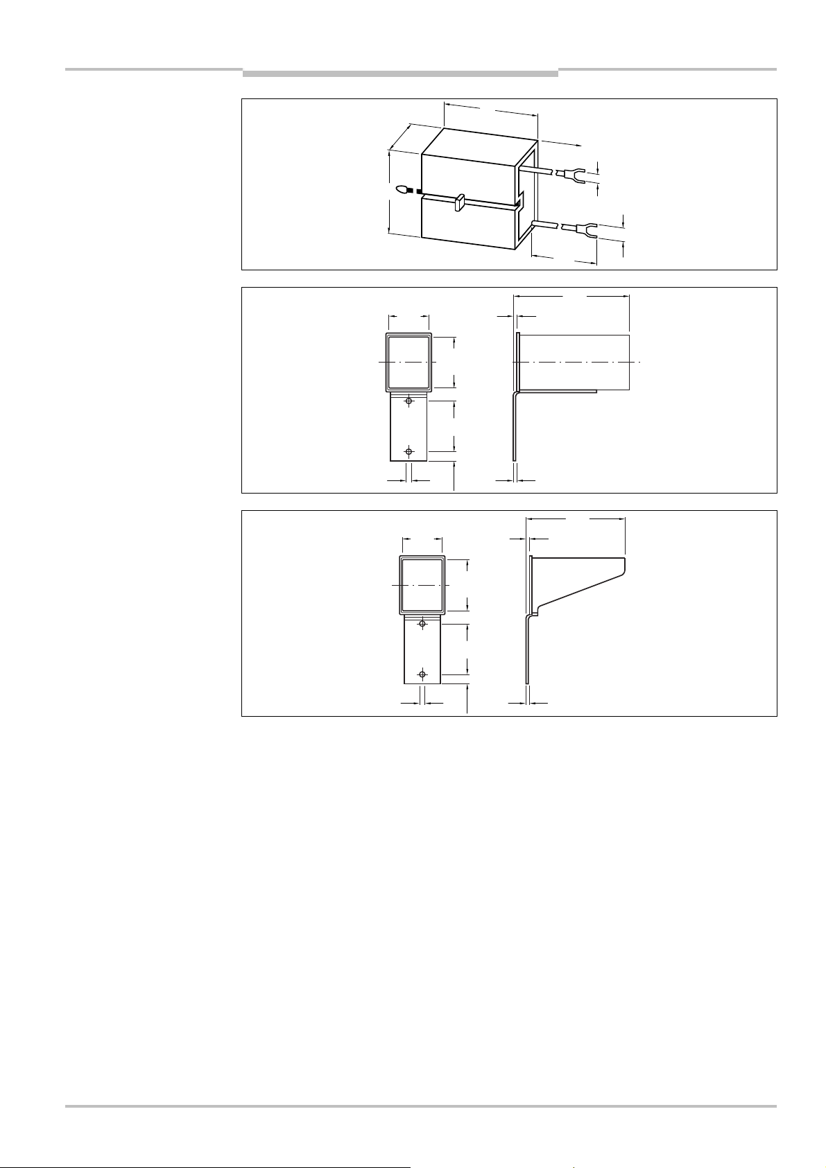
Fig. 19:
WSU/WEU26
-
3
Fig. 20:
Deflector mirr
or
Fig. 21:
Bracket for PSK1
Cover
Cover screws
Torque:
PG13.5
Ordering information
WSU/WEU263
10.4 Dimensional drawings
PSK1
65
156
65
14
18 ± 0.5 Nm
50
67
34
M6 x 8
17.5
128
15.5
116
torque:
2.0 ± 0.5 Nm
65
95
96
deflector mirror 1
124
149
160
177
7
ø
38
96
100
M8 x 30 SW13
20
26
40
43
22
M6 M6
16.5
33.5
63
14
8.5
20
58
71
M8 x 30 SW13
2.5
10
8013338/YTA4/2016-03-24 © SICK AG • Industrial Safety Systems • Germany • All rights reserved 37
Subject to change without notice
Page 38

Chapter 10 Operating Instructions
Fig. 22:
Spring fastening for
Fig. 23:
Deflector mirro
r
Fig. 24:
Mounting bracket
Fig. 25:
Arc-su
ppression
Ordering information
WSU/WEU263
deflector mirror PSK1
PSK45 (M = Middle of the
mirror surface)
80
96.5
M
WSU/WEU
76
40.5
64.5
64.5
8.5
46.5
39.5
40
°
45
8.5
146.5
6.5
65
65
6
51
82
51
6.5
20˚
60˚
69.5
9
8.5
63
ø 5.5
80
9
element 115 ... 230 V
38 © SICK AG • Industrial Safety Systems • Germany • All rights reserved 8013338/YTA4/2016-03-24
27
13
20
250
3.8
6.3
135
Subject to change without notice
Page 39
Operating Instructions Chapter 10
Fig. 26:
Arc-suppression
Fig. 27:
Dust protection tube
Fig. 28:
Weather protectio
n
Ordering information
WSU/WEU263
element 24 V
35
15
30
5
0.5
65.565
7
11.8
250
3.8
6.3
135
140
4
3
119
50.5
65.565
73
12.3
4
8013338/YTA4/2016-03-24 © SICK AG • Industrial Safety Systems • Germany • All rights reserved 39
Subject to change without notice
Page 40

Chapter 11 Operating Instructions
WSU/WEU263
Annex
11 Annex
11.1 Compliance with EU directives
EU declaration of conformity (excerpt)
The undersigned, representing the following manufacturer herewith declares that the
product is in conformity with the provisions of the following EU directive(s) (including all
applicable amendments), and that the respective standards and/or technical
specifications are taken as the basis.
Complete EU declaration of conformity for download: www.sick.com
40 © SICK AG • Industrial Safety Systems • Germany • All rights reserved 8013338/YTA4/2016-03-24
Subject to change without notice
Page 41

Operating Instructions Chapter 11
WSU/WEU26-3
Annex
11.2 Checklist for the manufacturer
Κ
Checklist for the manufacturer/installer for the installation of electro-
sensitive protective equipment (ESPE)
Details about the points listed below must be present at least during initial commissioning – they are, however,
dependent on the respective application, the specifications of which are to be controlled by the manufacturer/installer.
This checklist should be retained and kept with the machine documentation to serve as reference during recurring
tests.
1.
Have the safety rules and regulations been observed in compliance with the
directives/standards applicable to the machine?
2. Are the applied directives and standards listed in the declaration of conformity? Yes No
3.
Does the protective device comply with the required PL/SIL claim limit and PFHd in accordance
with EN ISO 13849-1/EN 62061 and the required type in accordance with IEC 61496-1?
4.
Is the access to the hazardous area/hazardous point only possible through the protective field
of the ESPE?
5.
Have appropriate measures been taken to protect (mechanical protection) or monitor
(protective devices) any persons or objects in the hazardous area when protecting a hazardous
area or hazardous point, and have these devices been secured or locked to prevent their
removal?
6.
Are additional mechanical protective measures fitted and secured against manipulation which
prevent reaching under, over or around the ESPE?
7.
Has the maximum stopping and/or stopping/run-down time of the machine been measured,
specified and documented (at the machine and/or in the machine documentation)?
8.
Has the ESPE been mounted such that the required minimum distance from the nearest
hazardous point has been achieved?
9. Are the ESPE devices correctly mounted and secured against manipulation after adjustment? Yes No
10. Are the required protective measures against electric shock in effect (protection class)? Yes No
11.
Is the control switch for resetting the protective device (ESPE) or restarting the machine present
and correctly installed?
12.
Are the outputs of the ESPE (OSSD) integrated according to required PL/SILCL compliant with
EN ISO 13849-1/EN 62061 and does the integration correspond to the comply with the circuit
diagrams?
13.
Has the protective function been checked in compliance with the test notes of this
documentation?
14. Are the specified protective functions effective at every operating mode that can be set? Yes No
15. Are the switching elements activated by the ESPE, e.g. contactors, valves, monitored? Yes No
16. Is the ESPE effective over the entire period of the dangerous state? Yes No
17.
Once initiated, will a dangerous state be stopped when switching the ESPE on or off and when
changing the operating mode, or when switching to another protective device?
18.
Has the information label for the daily check been attached so that it is easily visible for the
operator?
Yes No
Yes No
Yes No
Yes No
Yes No
Yes No
Yes No
Yes No
Yes No
Yes No
Yes No
Yes No
This checklist does not replace the initial commissioning, nor the regular inspection by qualified safety personnel.
8013338/YTA4/2016-03-24 © SICK AG • Industrial Safety Systems • Germany • All rights reserved 41
Subject to change without notice
Page 42

Chapter 11 Operating Instructions
Annex
WSU/WEU26-3
11.3 List of tables
Tab. 1: Overview on disposal by components ...................................................................9
Tab. 2: Receiver variants................................................................................................ 11
Tab. 3: Diagnostics LEDs WSU26-3 ............................................................................... 12
Tab. 4: Diagnostics LEDs WEU26-3................................................................................ 12
Tab. 5: Height of the beams above the floor.................................................................. 15
Tab. 6: Formula for the calculation of the minimum distance to reflective surfaces..... 17
Tab. 7: Reduction in the scanning range on the usage of deflector mirrors with
= 90°.............................................................................................................. 20
Tab. 8: Distances of the deflector mirrors...................................................................... 21
Tab. 9: Assignment of the sensor contacts, sender WSU26-3....................................... 23
Tab. 10: Assignment of the sensor contacts, receiver WEU26-3 ..................................... 24
Tab. 11: Examples for arc-suppressors............................................................................ 25
Tab. 12: Diagnostics LEDs WSU26-3 ............................................................................... 31
Tab. 13: Diagnostics LEDs WEU26-3................................................................................ 32
Tab. 14: Technical specifications..................................................................................... 33
Tab. 15: Ordering information devices............................................................................. 36
Tab. 16: Ordering information deflector mirrors............................................................... 36
Tab. 17: Ordering information accessories ...................................................................... 36
42 © SICK AG • Industrial Safety Systems • Germany • All rights reserved 8013338/YTA4/2016-03-24
Subject to change without notice
Page 43

Operating Instructions Chapter 11
WSU/WEU26-3
Annex
11.4 List of illustrations
Fig. 1: Key data for the WSU/WEU26-3 devices............................................................10
Fig. 2: Diagnostics LEDs WSU26-3 ...............................................................................12
Fig. 3: Diagnostics LEDs WEU26-3 ................................................................................12
Fig. 4: Access guarding with WSU/WEU26-3.................................................................13
Fig. 5: Safety distance S to the light beam ....................................................................15
Fig. 6: Minimum distance to reflective surfaces............................................................17
Fig. 7: Graph, minimum distance from reflective surfaces............................................17
Fig. 8: Mounting two WSU/WEU26-3 devices in series .................................................18
Fig. 9: Mounting possibilities using mounting brackets.................................................19
Fig. 10: Hazardous area protected on several sides........................................................20
Fig. 11: Two-beam protection with one system WSU/WEU26-3 ......................................21
Fig. 12: Incorrect alignment of sender and receiver........................................................21
Fig. 13: Correct alignment of sender and receiver...........................................................21
Fig. 14: Assignment of the sensor contacts, sender WSU26-3........................................23
Fig. 15: Assignment of the sensor contacts, connection diagram WEU26-3 on
UE43...................................................................................................................24
Fig. 16: Circuit for an inductive load................................................................................25
Fig. 17: WSU26-3 sender unit and WEU26-3 receiver unit..............................................26
Fig. 18: Mounting the laser alignment aid AR60 .............................................................27
Fig. 19: WSU/WEU26-3 ...................................................................................................37
Fig. 20: Deflector mirror PSK1.........................................................................................37
Fig. 21: Bracket for PSK1 deflector mirror 1....................................................................37
Fig. 22: Spring fastening for deflector mirror PSK1.........................................................38
Fig. 23: Deflector mirror PSK45 (M = Middle of the mirror surface)................................38
Fig. 24: Mounting bracket WSU/WEU..............................................................................38
Fig. 25: Arc-suppression element 115 ... 230 V ..............................................................38
Fig. 26: Arc-suppression element 24 V............................................................................39
Fig. 27: Dust protection tube ...........................................................................................39
Fig. 28: Weather protection .............................................................................................39
8013338/YTA4/2016-03-24 © SICK AG • Industrial Safety Systems • Germany • All rights reserved 43
Subject to change without notice
Page 44

8013338/YTA4/2016-03-24 ∙ REIPA/XX (2016-04) ∙ A4 sw int44
Australia
+61 3 9457 0600
Phone
1800 334 802 – tollfree
E-Mail sales@sick.com.au
Austria
Phone +43 (0)22 36 62 28 8-0
E-Mail office@sick.at
Belgium/Luxembourg
Phone +32 (0)2 466 55 66
E-Mail info@sick.be
Brazil
Phone +55 11 3215-4900
E-Mail marketing@sick.com.br
Canada
Phone +1 905 771 14 44
E-Mail information@sick.com
Czech Republic
Phone +420 2 57 91 18 50
E-Mail sick@sick.cz
Chile
Phone +56 2 2274 7430
E-Mail info@schadler.com
China
Phone +86 4000 121 000
E-Mail info.china@sick.net.cn
Denmark
Phone +45 45 82 64 00
E-Mail sick@sick.dk
Finland
Phone +358-9-2515 800
E-Mail sick@sick.fi
France
Phone +33 1 64 62 35 00
E-Mail info@sick.fr
Gemany
Phone +49 211 5301-301
E-Mail info@sick.de
Great Britain
Phone +44 (0)1727 831121
E-Mail info@sick.co.uk
Hong Kong
Phone +852 2153 6300
E-Mail ghk@sick.com.hk
Hungary
Phone +36 1 371 2680
E-Mail office@sick.hu
India
Phone +91–22–4033 8333
E-Mail info@sick-india.com
Israel
Phone +972-4-6881000
E-Mail info@sick-sensors.com
Italy
Phone +39 02 27 43 41
E-Mail info@sick.it
Japan
Phone +81 (0)3 5309 2112
E-Mail support@sick.jp
Malaysia
Phone +603 808070425
E-Mail enquiry.my@sick.com
Netherlands
Phone +31 (0)30 229 25 44
E-Mail info@sick.nl
New Zealand
Phone +64 9 415 0459
0800 222 278 – tollfree
E-Mail sales@sick.co.nz
Norway
Phone +47 67 81 50 00
E-Mail sick@sick.no
Poland
Phone +48 22 837 40 50
E-Mail info@sick.pl
Romania
Phone +40 356 171 120
E-Mail office@sick.ro
Russia
Phone +7-495-775-05-30
E-Mail info@sick.ru
Singapore
Phone +65 6744 3732
E-Mail sales.gsg@sick.com
Slovakia
Phone +421 482 901201
E-Mail mail@sick-sk.sk
Slovenia
Phone +386 (0)1-47 69 990
E-Mail office@sick.si
South Africa
Phone +27 11 472 3733
E-Mail info@sickautomation.co.za
South Korea
Phone +82 2 786 6321
E-Mail info@sickkorea.net
Spain
Phone +34 93 480 31 00
E-Mail info@sick.es
Sweden
Phone +46 10 110 10 00
E-Mail info@sick.se
Switzerland
Phone +41 41 619 29 39
E-Mail contact@sick.ch
Taiwan
Phone +886 2 2375-6288
E-Mail sales@sick.com.tw
Thailand
Phone +66 2645 0009
E-Mail tawiwat@sicksgp.com.sg
Turkey
Phone +90 (216) 528 50 00
E-Mail info@sick.com.tr
United Arab Emirates
Phone +971 (0) 4 88 65 878
E-Mail info@sick.ae
USA/Mexico
Phone +1(952) 941-6780
1 (800) 325-7425 – tollfree
E-Mail info@sick.com
Vietnam
Phone +84 8 62920204
E-Mail Ngo.Duy.Linh@sicksgp.com.sg
More representatives and agencies
at www.sick.com
SICK AG | Waldkirch | Germany | www.sick.com
 Loading...