

Page 1
TECHNICAL DESCRIPTION
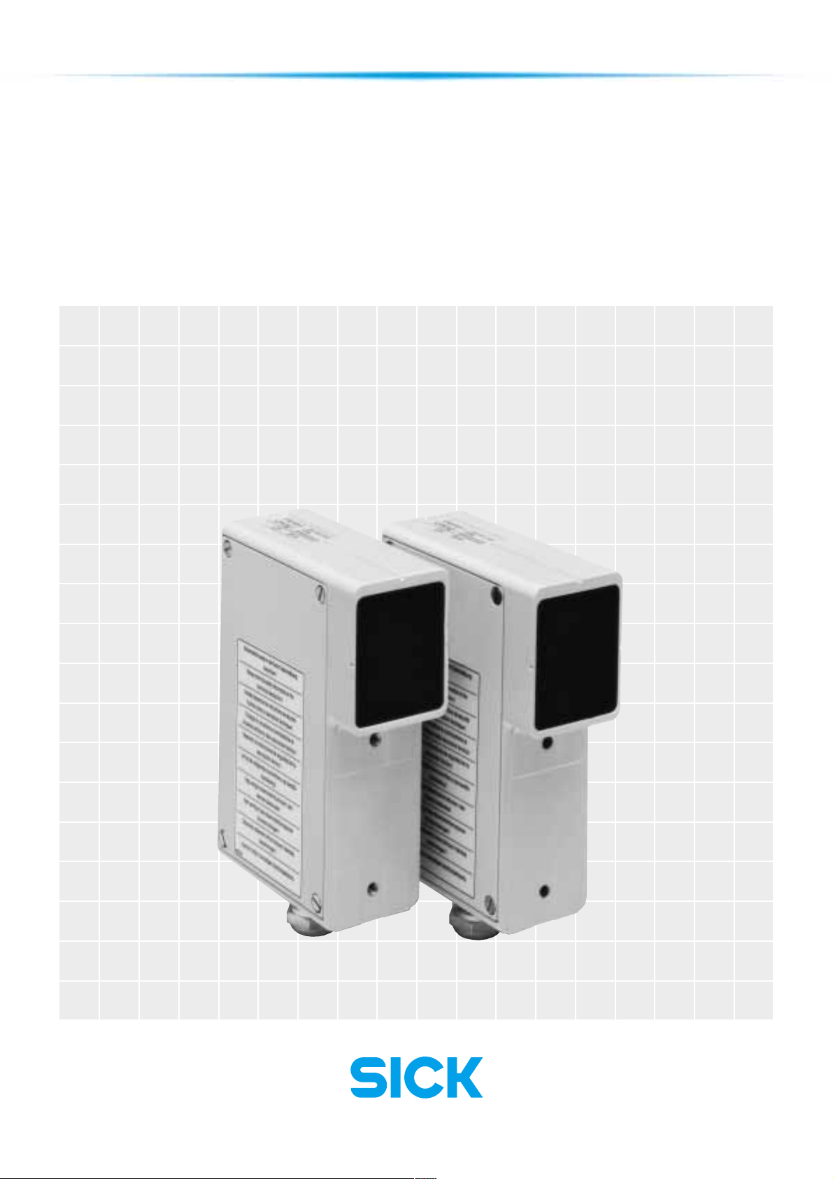
WSU 26/2 – WEU 26/2
Photoelectric Safety Switch
‡ EASY INSTALLATION †
‡ UNIVERSAL USABILITY†
‡ SOLID CONSTRUCTION †
Page 2
Contents
SICK WSU 26/2 – WEU 26/2
1 General Introduction 3
2 Device/System
Construction 4
3 Description of Function 4
4
Possible Areas of Application
and Application Conditions
4.1 Possible Areas
of Application 5
4.2 Application Conditions 5
5 Mechanical Arrangement
and Mounting 6
5.1 Safety Distance 6
5.2 Mechanical Mounting 7
5.3 Multiple Safeguarding 8
5.3.1 Mutual Interference 8
5.4 Corner Mirrors 10
6 Mounting 11
6.1 Mounting Requirements 11
6.2 Detecting Reflections 11
7 Electrical Connection 13
7.1 General 13
7.2 Wiring Diagram 14
12 Technical Data 25
13 Dimensional Drawing 26
14
At a glance: What is new?
15 Selection Table,
WSU/WEU 32
15.1 Conversion List 33
5
16 Selection Table,
Accessories 34
Standards and
Regulations
To be observed in use
and installation
Approvals
EU Europe
EC prototype test conducted by
31
BG - Berufsgenossenschaft
(Trade association)
Fachausschuß Eisen und Metall III
(Technical committee
for iron and metal III)
Graf-Recke-Str. 69
D-40239 Düsseldorf
Approval number: 97074
8 Commissioning 22
8.1 Alignment of WSU and
WEU 22
8.2 Alignment of WSU and
WEU with Alignment Aid
AR 60 22
8.3 Checking 22
9 Maintenance 23
10 Commissioning 23
11 Malfunctions 23
11.1 Diagnostic Elements 23
This technical description must be observed when installing and
commissioning the WSU 26/2 - WEU 26/2. Inspection and
commissioning must be carried out by specialists, if this is specified in the
directives or guidelines.
2
Warning
Failure to observe
may result in
dangerous operation
Usage
Information regarding
how to use the
product correctly
and efficiently
Generally recognized technical
regulations and quality assurance
system ISO 9000 are carefully
applied during the development
and production of SICK
products.
8 008 692/9-12-99 Technical Description · WSU/WEU 26-2 © SICK AG · Safety Systems · Germany · All rights reserved
Page 3
SICK WSU 26/2 – WEU 26/2
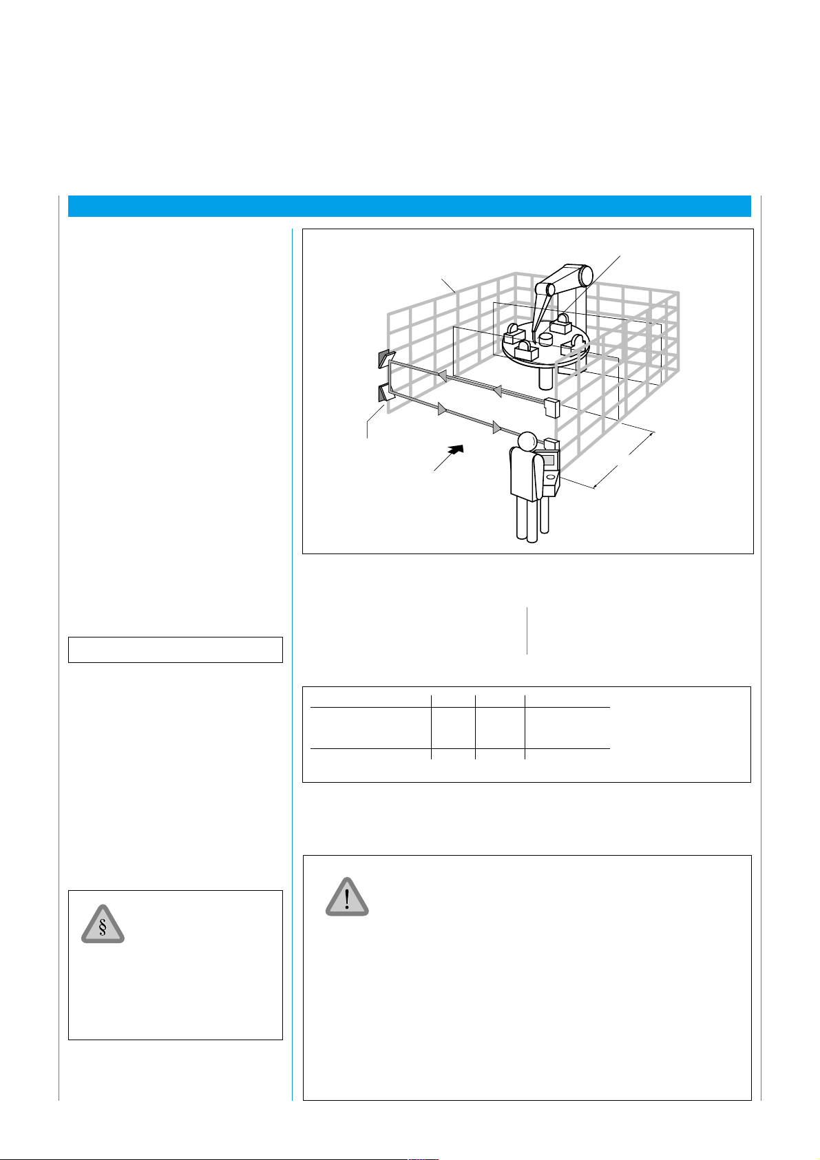
1 General Introduction
1 General Introduction
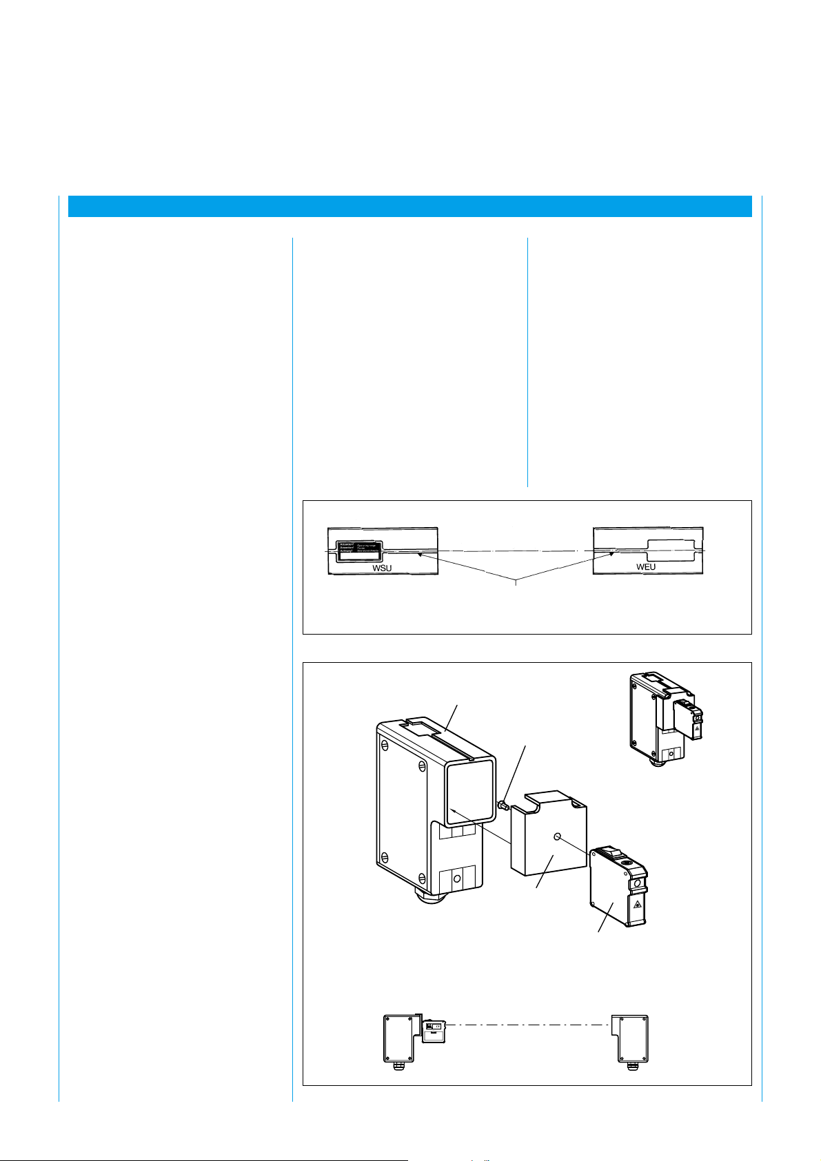
The WSU 26/2 / WEU 26/2
photoelectric safety switch is a single-beam non-contact protective
system. It consists of a WSU light
sender and a WEU light receiver.
The light beam between the
emitting and receiving units
provides access protection for
hazardous areas.
The safety switch is designed for
industrial applications. Its features
include
‡ universal usability
‡ easy installation
‡ solid construction
‡ heated front screen, i.e. it can be
deployed even in unfavorable
ambient conditions.
The WSU/WEU complies with
safety requirements according to
pr EN 50.100, safety category type 4.
The following key data are
applicable in practical use:
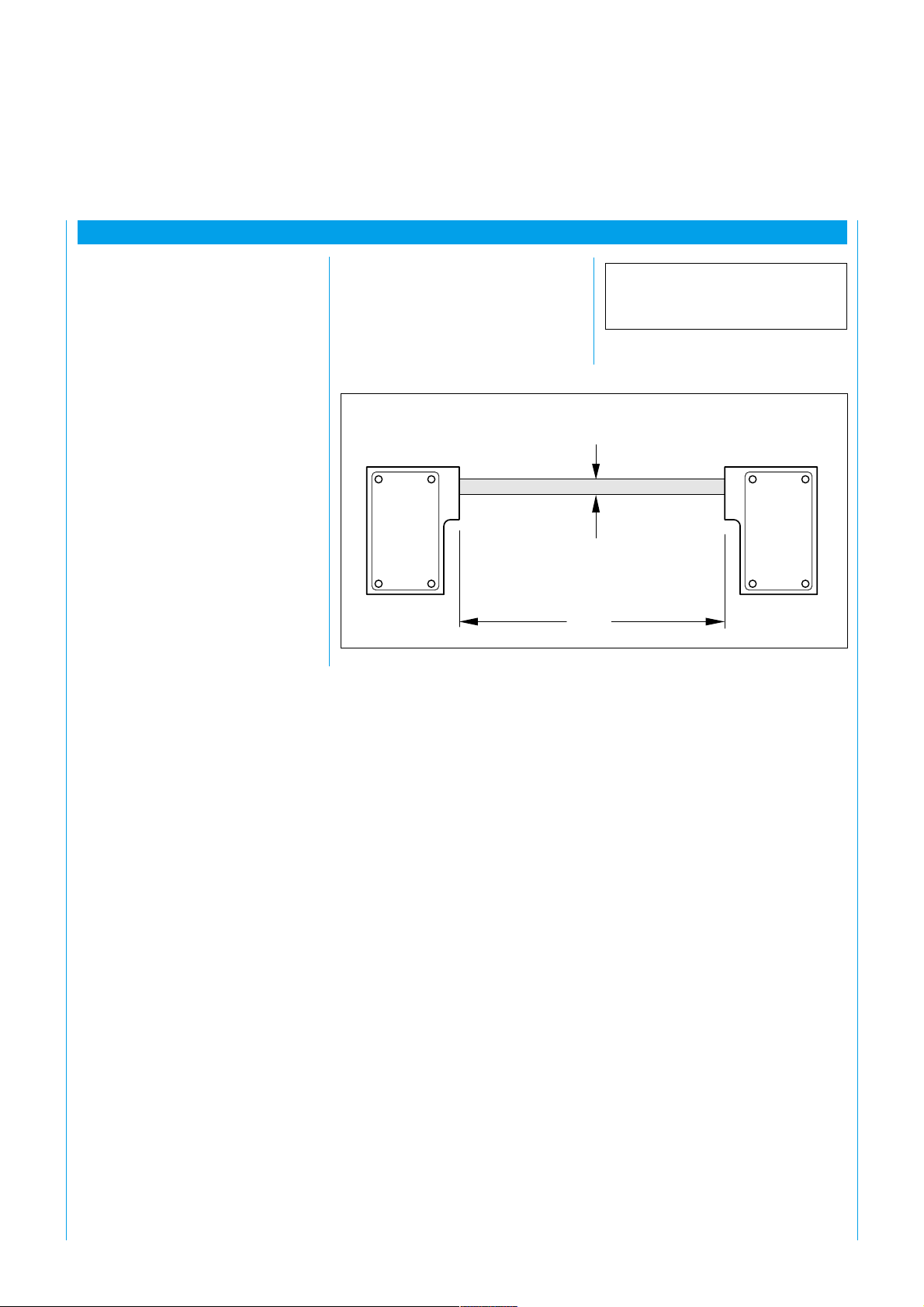
Beam diameter
WSU WEU
Fig. 1: System construction of the WSU 26/2 / WEU 26/2 photoelectric safety switch
Scanning range 0.5 ... 18 m
15 ... 70 m
Beam diameter 23 mm
23 mm
Range
8 008 692/9-12-99 Technical Description · WSU/WEU 26-2 © SICK AG · Safety Systems · Germany · All rights reserved
3
Page 4
3 Description of Function
2 Device/System Construction
SICK WSU 26/2 – WEU 26/2
The WSU/WEU comprises:
‡ WSU 26/2 sender unit and
‡ WEU 26/2 receiver unit
Each complete break in the light
beam between the light sender and
light receiver triggers a signal which
can be used to immediately stop
the dangerous movement of the
power-driven machinery
(abbreviated as ”PDM”).
The WSU/WEU 26/2 must not be used as a hand or finger guard.
3 Description of Function
The WSU and WEU are mounted
separately in die-cast housings. Each
has its own power supply (Fig. 2).
The WSU contains a clock
generator and the sender diode.
The diode emits infrared pulses at
the clock rate set by the generator,
which are evaluated by the receiver
unit WEU if the light path is
uninterrupted.
The WEU contains the output
relays A and B, which pick up if the
light path is uninterrupted.
If the light path or the connection
between terminals 10 and 11 on
the WSU is interrupted (testing),
both relays are released.
The WSU 26/2 / WEU 26/2 serves
as a protective cut-off device to
protect hazardous areas on powerdriven machinery. The machinery
may be:
‡ plastics machinery
‡ stackers
‡ settling machinery
in the stoneworking industry
‡ machining centers
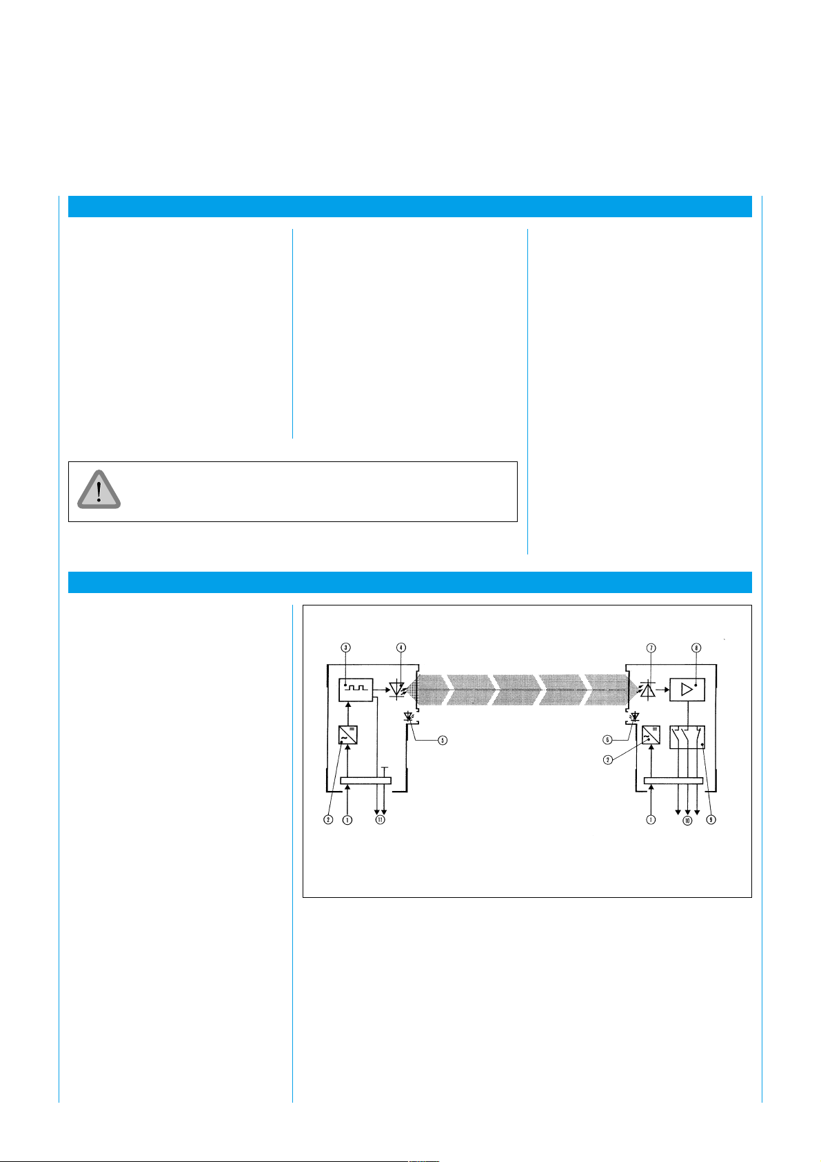
1 Connection
for power supply
2 Power supply
3 Clock generator
4 Sender diode
5 LED, WSU
6 LED, WEU
7 Photoelectric converter
8 Amplifier
9 Relay with positively-driven contacts
10 Outputs
11 Test contact
Fig. 2: Principle of function of the WSU/WEU 26/2, AC version
4
8 008 692/9-12-99 Technical Description · WSU/WEU 26-2 © SICK AG · Safety Systems · Germany · All rights reserved
Page 5

SICK WSU 26/2 – WEU 26/2
4 Possible Areas of Application and Application Conditions
4 Possible Areas of Application
4.1 Possible Areas
of Application
The WSU/WEU provides access
protection for hazardous areas
(Fig. 3).
4.2 Application
Conditions
Safe cut-off can only be effected
when the light beam diameter of
23 mm is fully covered.
The protective function of the
WSU/WEU is ensured when the
conditions set out in the adjacent
box are met.
The power-driven machinery (”PDM”) must be
controllable by electrical means.
The dangerous movement of the machine must be able
to be stopped at any time.
The WSU/WEU must be positioned so that entry into
the hazardous area is only possible by breaking the light
beam.
The command unit must be positioned so that it cannot
be activated from the hazardous area.
8 008 692/9-12-99 Technical Description · WSU/WEU 26-2 © SICK AG · Safety Systems · Germany · All rights reserved
5
Page 6
5 Mechanical Arrangement
5 Mechanical Arrangement and Mounting
SICK WSU 26/2 – WEU 26/2
5.1 Safety distance
The WSU/WEU must be attached
such that, if the light beam is
broken during hazardous
movement of the machinery, the
point-of-operation can only be
reached when this hazardous
movement has ceased. For this
purpose, a safety distance S must
be maintained between the nearest
boundary of the point-of-operation
and the light beam (Fig. 4). The
safety distance depends on the
machine stopping time and on the
approach speed of the personnel.
The machine stopping time must be
determined by repeating
measurements under practical
conditions. 1.6 m/s is the
recommended approach speed.
The safety distance is calculated as
follows:
S = v (t
+ t2) + C
1
Mechanical
safeguarding
Entry/exit
guarding
with
WSU/WEU
Fig. 4: Safety distance to light beam
Direction
of entry
into
hazardous
area
Table 1 shows which C value must
be used for which application.
Point-of-operation
S
S Safety distance (mm)
v Approach speed
1.6 m/s
t
Machine stopping time (ms)
1
t
Response time of WEU (22 ms)
2
C Dependent on number of beams
(1, 2, or 3), see Table 1
pr EN 999
Safety of machinery
Approach speed of body parts
for arrangement of protective
systems
6
Number of beams 01 02 03
Height of beam(s) 750 400 0300
above floor (mm) 900 0700
1100
C 1200 850 0850
Table 1: Height of beams above floor
The WSU/WEU must be attached such that, if the light beam is
broken during hazardous movement of the machinery, the pointof-operation can only be reached when the power-driven
machinery is no longer in a hazardous state.
For this purpose, a safety distance must be maintained between the
light beam and the nearest boundary of the point-of-operation.
This safety distance is determined according to pr EN 999.
People within the hazardous area but outside the light beam are
not detected. It must, however, be ensured that any hazardous
state can only be initiated when there is no one in the hazardous
area.
Use and mounting of the protective systems is subject to the relevant official rules and regulations. These provisions differ depending
on the area of application.
8 008 692/9-12-99 Technical Description · WSU/WEU 26-2 © SICK AG · Safety Systems · Germany · All rights reserved
Page 7
SICK WSU 26/2 – WEU 26/2
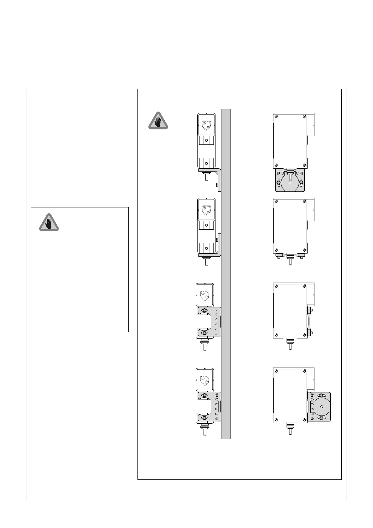
5.2 Mechanical Mounting
The WSU and WEU units can be
mounted on one of the sides of
their housing or using the mounting
bracket, depending on site
circumstances. The mounting
bracket greatly assists alignment.
The devices can be mounted in any
operating position. However, the
WSU and WEU should be
mounted such that the axis of the
light beam emitted by the WSU
always matches the axis of the
WEU optic (alignment sight).
The mounting brackets should be
affixed so that all fixing screws are
easily accessible for alignment
purposes. Figure 5 shows examples.
The devices should be attached
such that the opposing device can
be aligned in the alignment sight.
When using the
15 + PE plug,
mounting modes
a and b
are not possible.
Order number
Mounting bracket
2 007 900
a
b
If, for reasons of space, the devices
need to be arranged as shown in
Figures 5 a and b, hexagon screws
must be used.
c
d
Fig. 5: Mounting options using a mounting bracket
8 008 692/9-12-99 Technical Description · WSU/WEU 26-2 © SICK AG · Safety Systems · Germany · All rights reserved
7
Page 8
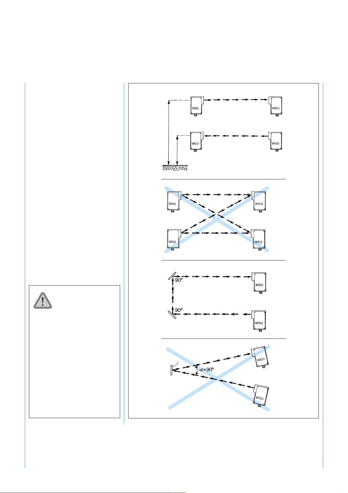
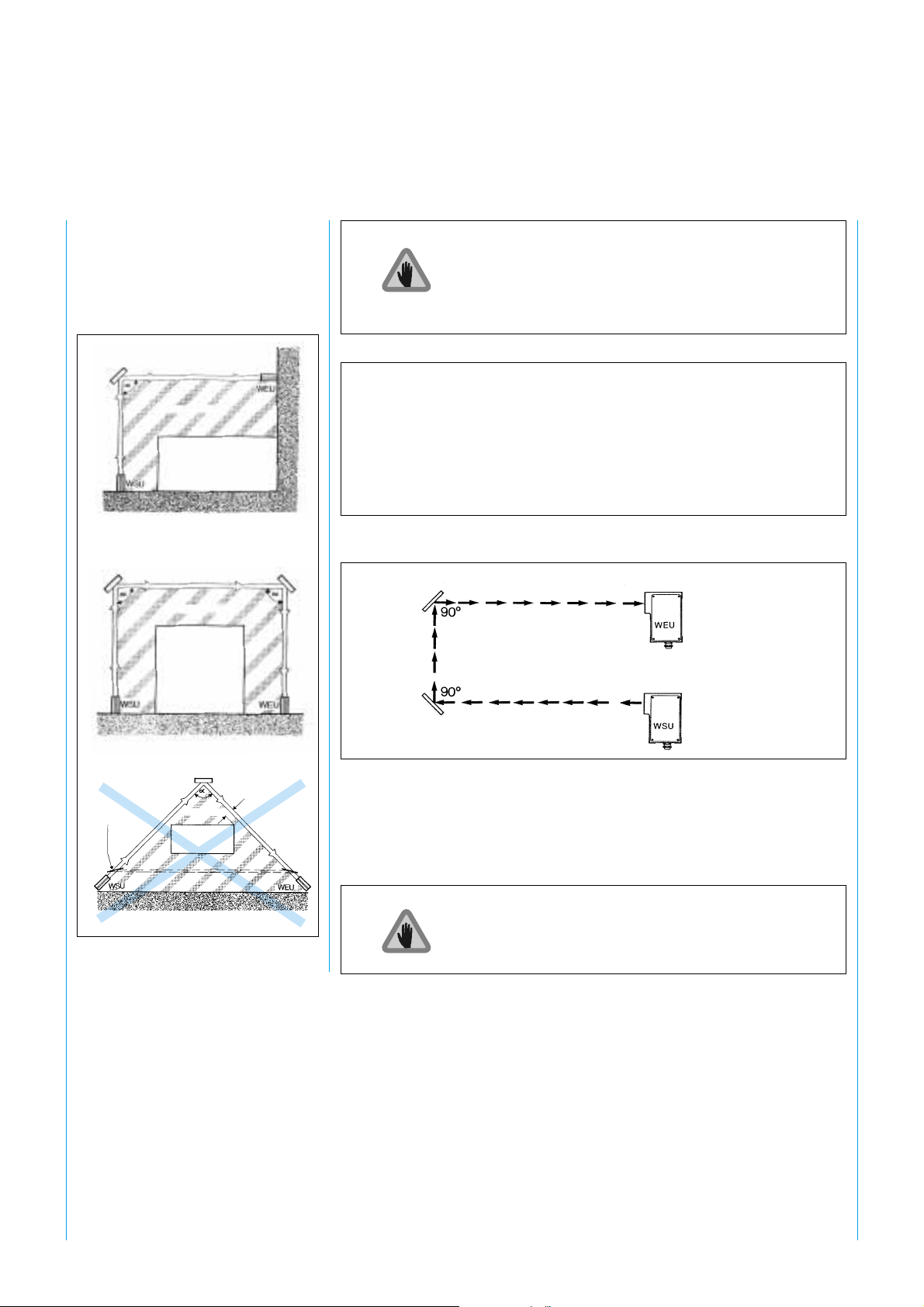
5.3 Multiple
Safeguarding
When using two WSU/WEU units
in a protective system, the
possibility of mutual interference
must be excluded. Since the light
beam of the WSU diverges, the
cross-section of the beam increases
as the distance between the WSU
and WEU grows. The following
conditions must therefore be met
when arranging the WSU/WEU:
SICK WSU 26/2 – WEU 26/2
approx. 900
approx. 400
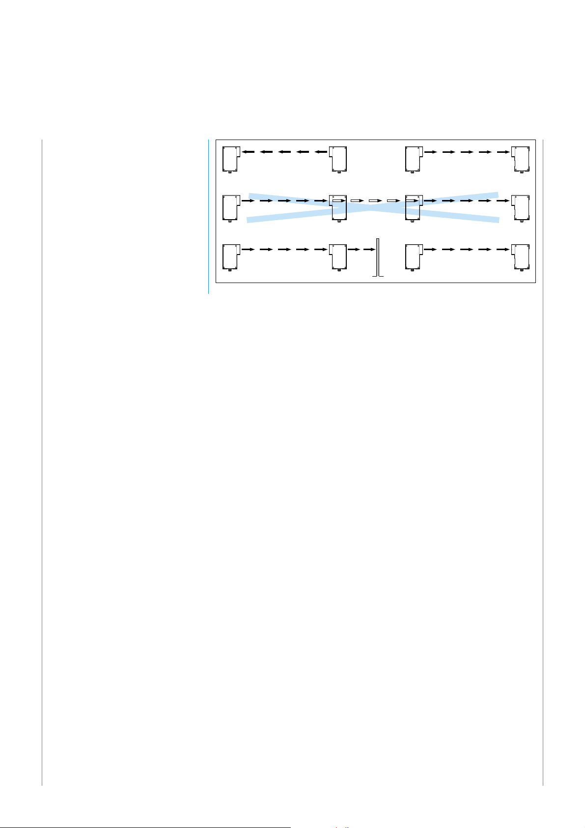
5.3.1 Mutual Interference
The light beam of the WSU must
only be received by the
corresponding WEU. To prevent
mutual interference between
several WSU/WEU installations
arranged adjacent to or above each
other, the specified beam diameters
must be taken into account when
mounting the devices (Fig. 6).
There are two versions
of the WSU, for
operating ranges
0.5 ... 18 m and
15 ... 70 m. The WSU
must not be used for
operating ranges below
15 m. The operating
range is given on the
rating plate.
Mutual interference is possible
Corner mirror
Corner mirror
Corner mirror
Fig. 6: Safeguarding a hazardous area with WSU/WEU
8
8 008 692/9-12-99 Technical Description · WSU/WEU 26-2 © SICK AG · Safety Systems · Germany · All rights reserved
Page 9
SICK WSU 26/2 – WEU 26/2
WEU
WSU
WSU
WSU
WEU
WEU
Fig. 7: Mounting of two WSU/WEU units in series
WSU
WSU
WSU
WEU
WEU
WEU
8 008 692/9-12-99 Technical Description · WSU/WEU 26-2 © SICK AG · Safety Systems · Germany · All rights reserved
9
Page 10
5.4 Corner mirrors
SICK WSU 26/2 – WEU 26/2
In conjunction with corner mirrors,
the WSU/WEU provides multisided, two-beam access protection
(Fig. 8 and 9).
Corner mirror
Hazardous area
Power-driven
machinery (PDM)
Corner mirror
Hazardous area
Power-driven
machinery
(PDM)
Corner mirror
The use of corner mirrors reduces the scanning range
of the WSU/WEU system as cited in the table.
Number of mirrors Reduced scanning range Reduced scanning range
0.5 ... 18 m WSU 15 ... 70 m WSU
1 17 m 67 m
2 15.5 m 61 m
3 13 m 51 m
4 11 m 42 m
Tab. 2: Reduction in scanning range when using corner mirrors
Corner mirror
Safety distance
Reflection
possible
KA
Fig. 8: Multi-sided protection of hazardous
areas
too small
Corner mirror
Fig. 9: Two-beam protection with a WSU/WEU 26 system
The use of more than 2 mirrors requires a very accurate
alignment.
10
8 008 692/9-12-99 Technical Description · WSU/WEU 26-2 © SICK AG · Safety Systems · Germany · All rights reserved
Page 11
SICK WSU 26/2 – WEU 26/2
6 Mounting
6.1 Mounting
Requirements
The devices should be mounted
and connected in accordance with
the on-site application conditions
and connections, taking account of
the following:
The scanning range is based on the width of the area being
protected. Bypassing or encircling must be prevented by suitable
(mechanical) means.
Where one or more WSU/WEU units are used, the height and
number of light beams must comply with the applicable
regulations.
There must be no reflective surfaces in the emitting or receiving
beam path.
The minimum distance must be maintained.
6 Mounting
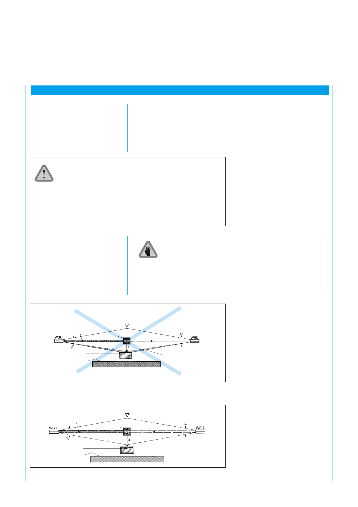
6.2 Detecting
Reflections
The light beam must not be
unintentionally reflected back to the
receiver by reflective surfaces.
Reflections can be detected as
follows:
Entry direction
Central beam
Reflective object
(e.g. material container)
Boundary
of point-ofoperation
Fig. 10: Incorrect mounting: reflective object in divergent light beam. No detection of the
obstacle due to reflection. No protection.
Entry direction
Central beam
Cover the light beam between the sender and receiver fully with
an obstacle (100 mm x 100 mm) and slowly move the obstacle
from the sender unit to the receiver unit.
While this is happening the green LED on the WEU must not
light up. If it lights up even just briefly during this check, reflection
is occurring.
See also 8. Commissioning.
Beam array
broken
Beam array
broken
Reflective object
(e.g. material container)
Boundary
of point-ofoperation
Fig. 11: Correct mounting, correctly aligned: reflective object outside divergent light beam.
No reflection. The obstacle is clearly detected.
8 008 692/9-12-99 Technical Description · WSU/WEU 26-2 © SICK AG · Safety Systems · Germany · All rights reserved
11
Page 12

a (mm)
SICK WSU 26/2 – WEU 26/2
2500
WSU WEU
2000
1500
1000
500
400
300
200
100
Fig. 12: Distance a as a function of scanning range SR
4°
3
10
a
a
6
20
30
a (70 m)
4°
a (18 m)
RW (m)
9
12
40
15
50
18
60
21
70
12
8 008 692/9-12-99 Technical Description · WSU/WEU 26-2 © SICK AG · Safety Systems · Germany · All rights reserved
Page 13

SICK WSU 26/2 – WEU 26/2
7 Electrical Connection
7 Electrical Connection
7.1 General Introduction
Depending on type, the WSU/WEU
26/2 photoelectric safety switch is
available for a supply voltage of
‡ 24 V DC
‡ 115 V AC or
‡ 230 V AC.
The rating plate gives details.
Before connection, check that the
supply voltage and mains frequency
on-site are consistent with the
specifications on the rating plate.
The cable is fed through the PG
connector and connected inside the
device, or connected to the
equipment plug. The wiring diagram
is depicted again on the housing
cover of the respective device.
The two system components must
be of the same voltage version and
the same scanning ranges.
Single- or fine-wire conductors up
to 1.5 mm
2
can be connected to
the screwless terminals (to VDE
0607). Stripping length: 11 mm.
The electrical connection of the WSU/WEU must only
be made or changed with the power disconnected.
Unscrew the housing cover to connect the WSU/WEU
with a PG connector.
Arc-suppression elements are essential under inductive load!
Arc-suppression elements must be connected in parallel with
the inductance. Connection in parallel with the output contact
is not permitted.
Diodes must not be used as arc-suppression elements.
At least two outputs must be
connected to the downstream
machine controller (Fig. 20/21).
Each of the two outputs (NO
contacts) must be assigned an
electromagnetic switching element.
Guide values for arc-suppression elements
The enclosure rating for the devices
can only be guaranteed when the
cable is properly clamped in the PG
connector and the housing seals fit
perfectly. Where long leads are
used, the cable cross-sections
should be chosen to ensure the
Operating
voltage
C
R
Contact
in WEU
Consumers,
contactor
Operating voltage Order no. R C
V ΩµF
115 ... 230 6 001 224 220 0.22
24 6 001 225 100 2.2
Plastic-encapsulated; connecting wires NYAF 0.5
dia. with cable lugs; mounting with adhesive tape
or cable tie.
devices are always supplied with
the required voltage (see Technical
Data).
Tab. 3: Overview for arc-suppression elements
8 008 692/9-12-99 Technical Description · WSU/WEU 26-2 © SICK AG · Safety Systems · Germany · All rights reserved
13
Page 14

7.2 Wiring Diagram
SICK WSU 26/2 – WEU 26/2
31011
1/2
PE +24V
Fig. 13: Wiring diagram WSU/WEU for 24 V DC supply, with PG connector
0V 0V
31011
1/2
PE
1/2
+24V
1/2
456789
3
456789
3
PE
230V/
NN
115 V
Fig. 14: Wiring diagram WSU/WEU for AC supply, with PG connector
Connecting leads max. 1.5 mm
WSU
Test contact (10, 11)
Floating U 24 V DC
I 10 mA
Opening time t ≥ 50 ms
2
WEU
Outputs (4 - 9)
Umax. 250 V AC
Imax. 2 A per output
Imin. 0.02 A per output
PE
230V/
115 V
14
8 008 692/9-12-99 Technical Description · WSU/WEU 26-2 © SICK AG · Safety Systems · Germany · All rights reserved
Page 15

SICK WSU 26/2 – WEU 26/2
1/2
PE +24V
1/2
PE +24V
31011
1
2
0V
31011
5
6
0V
WSU 26/2 -131
231
1
B
A
2
G
F
3
3
4
Coded to
C
6
A or
D
5
E
4
Equipment plug
WSU 26/2 -133 WSU 26/2 -233
1
B
A
2
G
F
3
3
4
Equipment plug
Coded to
C
6
E or. 4
D
5
E
4
1
B
A
2
C
G
6
F
D
3
5
E
4
Equipment plug
Coded to
B or 1
3456789
1/2
3
2
1
PE +24V
0V
3456789
1/2
3
2
1
+24V 0V
PE
3456789
1/2
63
5
PE +24V 0V
WEU 26/2 -131
231
1
B
A
2
G
F
3
4
6
5
Coded to
C
6
D or 5
D
5
E
4
Equipment plug
WEU 26/2 -132
232
1
B
A
2
G
F
3
5
6
4
Coded to
C
6
E or 4
D
5
E
4
Equipment plug
WEU 26/2 -133
233
1
B
A
2
G
F
3
1
4
2
Equipment plug
Coded to
C
6
E or 4
D
5
E
4
Fig. 15: Wiring diagram WSU/WEU 26/2 for 24 V DC supply, interchangeable design
8 008 692/9-12-99 Technical Description · WSU/WEU 26-2 © SICK AG · Safety Systems · Germany · All rights reserved
15
Page 16

SICK WSU 26/2 – WEU 26/2
PE
PE
1/2
230 V/
115 V
1/2
230 V/
115 V
1
5
31011
3
2
N
31011
3
6
N
WSU 26/2 -121
-221
-111
1
-211
B
A
2
C
G
6
Coded to
F
D
3
4
C or 6
5
E
4
Equipment plug
WSU 26/2 -113 WSU 26/2 -213
1
B
A
2
C
G
6
F
3
4
Coded to
D
A or
5
E
4
Equipment plug
WSU 26/2 -123
Equipment plug
1
B
A
2
G
F
D
3
E
4
Equipment plug
1
B
A
2
C
G
6
F
D
3
5
E
4
C
6
Coded to
G or 2
5
-223
Coded to
F or 3
3456789
1/2
3
2
1
N
PE
230 V/
115 V
1/2
3456789
3
6
5
PE
N
230 V/
115 V
3456789
1/2
3
2
1
PE 230/
N
115 V
WEU 26/2 -112
-122
-212
-222
1
B
A
2
C
G
6
6
4
F
3
5
Coded to
D
F or 3
5
E
4
Equipment plug
WEU 26/2 -113
-213
-123
-223
1
B
4
2
1
A
2
G
F
3
Coded to
C
6
A or
D
5
E
4
Equipment plug
WEU 26/2 -111
-211
1
B
A
2
C
G
6
4
6
5
F
3
Coded to
D
G or 2
5
E
4
Equipment plug
WEU 26/2 -121
-221
1
B
A
2
C
G
6
F
3
Equipment plug
Coded to
D
C or 6
5
E
4
Fig. 16: Wiring diagram WSU/WEU 26/2 for AC supply, interchangeable design
WSU 26/2 -114
B
C
A
+24V/L1 (1/2)
1
2
0V/N (3)
Test (10)
Test (11)
3
4
5
PE
(...) Terminals on electronic card (...) Terminals on electronic card
ABC
1 24 V n.c. Test
L 1
(1/2) (10)
2 0V n.c. Test
N
(3) (11)
3 n.c. n.c. n.c.
4 n.c. n.c. n.c.
5 n.c. n.c. n.c.
-214
-124
-224
-134
-234
WEU
B
C
A
1
+24V/L1 (1/2)
2
0V/N (3)
3
4
S1 (4)
S1 (5)
5
PE
ABC
1 24 V n.c. n.c.
L 1
(1/2)
2 0V n.c. n.c.
N
(3)
3 n.c. n.c. n.c.
4 S 1 Ö 1/2 S 2
(4) (6) (8)
5 S 1 Ö 1/2 S 2
(5) (7) (9)
26/2 -114
Ö1/2 (6)
S2 (8)
S2 (9)
Ö1/2 (7)
-214
-124
-224
-134
-234
Fig. 17: Pin assignment WSU/WEU 26/2, AC/DC version with equipment plug (15 + PE)
16
8 008 692/9-12-99 Technical Description · WSU/WEU 26-2 © SICK AG · Safety Systems · Germany · All rights reserved
Page 17

SICK WSU 26/2 – WEU 26/2
63
29.5
47
PG 13.5
For line dia. 6 ... 9 mm
Pay attention
to coding!
29,5
29.5
15.2
15,2
55,2
55.2
11
Plugs and sockets:
DIN 43651: 6 + PE
with crimp contacts
78
M 26 x 1.5
M 26x1,5
dia. 28
ø 28
straight
Order no. 6 006 612
Fig. 18: Cable receptacles 6 + PE
7,5
7.5
25,5
22.5
53
angled
Order no. 6 006 613
For line dia. 4 ... 11 mm
Important: Mark plug and socket
unambiguously! The WEU socket
must not be connected
to the WSU plug
In some cases no longer complies with
requirements for clearance and
creepage distances (VDE 0160 05/88
and VDE 0110); see selection table.
PG
16
54.5
54.5
Order no. 2 019 076
63
PG
13.5
29.5
29.5
47
Order no. 2 019 075
63
29.5
29.5
Fig. 19: Cable receptacles 15 + PE
8 008 692/9-12-99 Technical Description · WSU/WEU 26-2 © SICK AG · Safety Systems · Germany · All rights reserved
17
Page 18

+24V
SICK WSU 26/2 – WEU 26/2
S1
2)
A1
A2PETo
C1 D1 PE C2 D2 PE T3 T4 C3 D3 PE C4 D4 14 24 32
PE T13 T14
X11 X12
WSU WEU
PE
1/2
10
11
3
PE
0V
+24V
Tes t
Tes t
+24V
0V
PE
1/2
4
8
9
5
3
PE
0 V
PE
Fig. 20: WSU/WEU 26/2 with Safety Interface LCU-X
k1
T21 T22
k2
X21 X22
K1
1)
x
y
k1
k2
x
13
23 31
y
z
k1
k2
z
K2
18
8 008 692/9-12-99 Technical Description · WSU/WEU 26-2 © SICK AG · Safety Systems · Germany · All rights reserved
Page 19
SICK WSU 26/2 – WEU 26/2
+24V
Start
10
WSU
1/2
311
+24V
Y32
Y35
1/2 4 8 6
WEU
3597
A1+ S52 S12 S22 S21 13 23 33 41 Y36
23
1
2
3
1
323
&
12 3
0V
0V
Outside switch cabinet separate line laying to receiver. Terminals 1, 3, 8 and 9 and 4, 5, 6 and 7 respectively in one plastic-sheathed
cable. Use PG 21 (order no. 5 305 978) and PG extension (order no. 5 306 052).
Fig. 21: WSU/WEU 26/2 with PNOZ 8 (Pilz); BIA-tested application no. 01131202933
8 008 692/9-12-99 Technical Description · WSU/WEU 26-2 © SICK AG · Safety Systems · Germany · All rights reserved
S11 Y1 Y2 A3 14 24 34 42 Y37 A2
19
Page 20
SICK WSU 26/2 – WEU 26/2
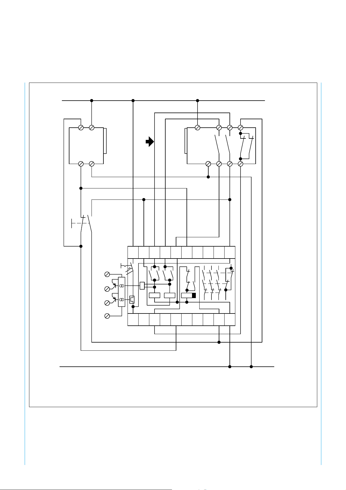
F
S
k 1
k 2
k 3
K 1 K 2 K 3 K 4
k 1
k 2
k 3
k 4
k 1
k 2
k 3
K1 to K4 Contactors or relays with positively-driven contacts
(not supplied)
Fu Arc-suppression, essential
S Command unit, e.g. pushbutton, key-operated switch etc.
Press button S to start, otherwise red LED on WEU remains lit.
x and y Insert in safe machine controller to interrupt the hazardous
movement. For safety reasons, the two contact rows (x and y)
must be inserted separately into the controller (two-channel).
z If, in exceptional cases, depending on the risk assessment, the
controller of the power-driven machinery is only of single-channel
design, contact row z can be used.
k 4
k 1
k 3
k 4
k 2
k 4
k 1
k 2
k 3
k 4
20
Fig. 22: Example of a connection with one WSU/WEU-26 system
8 008 692/9-12-99 Technical Description · WSU/WEU 26-2 © SICK AG · Safety Systems · Germany · All rights reserved
Page 21

SICK WSU 26/2 – WEU 26/2
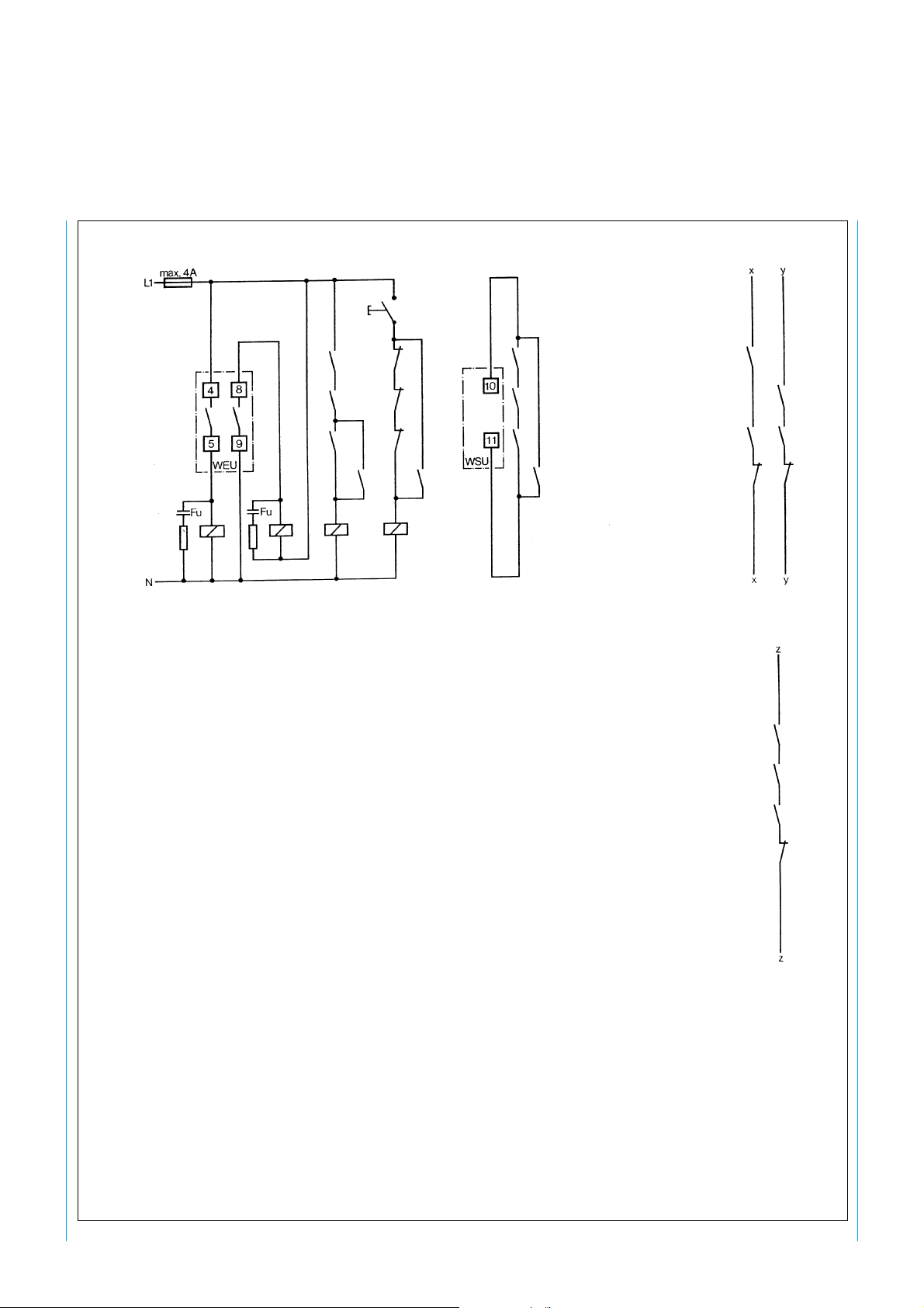
F
k 1
k 1
k 2
k 2
k 3
k 3
k 4
k 4
k 5
k 5
k 6
k 6
K 1 K 2 K 3 K 4 K 5 K 6
K1 to K6 Contactors or relays with positively-driven contacts
(not supplied)
Fu Arc-suppression, essential
S Command unit, e.g. pushbutton, key-operated switch etc.
Press button S to start, otherwise red LED on WEU remains lit.
x and y Insert in safe machine controller to interrupt the hazardous
movement. For safety reasons, the two contact rows (x and y)
must be inserted separately into the controller (two-channel).
z If, in exceptional cases, depending on the risk assessment, the
controller of the power-driven machinery is only of single-channel
design, contact row z can be used.
k 1
k 3
k 5
k 6
k 2
k 4
k 5
k 6
k 1
k 3
k 5
k 6
k 2
k 4
k 5
k 6
k 1
k 2
k 3
k 4
k 5
Fig. 23: Example of a connection with two WSU/WEU-26 systems
8 008 692/9-12-99 Technical Description · WSU/WEU 26-2 © SICK AG · Safety Systems · Germany · All rights reserved
k 6
21
Page 22
8 Commissioning
8 Commissioning
SICK WSU 26/2 – WEU 26/2
8.1 Alignment of WSU
and WEU
After checking the electrical
connections, loosen the fixing
screws on the WSU/WEU and
align the devices to each other
roughly using the alignment sight.
For further alignment keep pressing
button S or jumper terminals 10
and 11 on the WSU and switch on
the devices. When this is done the
LED on the WSU (yellow LED)
lights up (Fig. 24).
Align the devices to each other so
that the green and yellow LEDs on
the WEU light up.
For optimum alignment, ascertain
the limits of the emitting and
receiving ranges by swiveling the
WSU and WEU horizontally and
vertically one after the other. Just
before the limit of the optical range
the yellow LED on the WEU begins
to flash (Fig. 26). Beyond the
optical range the red LED on the
WEU lights up.
Then secure the WSU and WEU
respectively in the middle of the
resulting ranges. The yellow LED on
the WEU must be permanently lit.
8.3 Checking
Incorrect alignment may mean that
an obstacle is not detected or that
operational safety is not attained
investigate the diversion of the light
beam between the WSU and the
WEU (reflection may be occurring,
see 6.2 Detecting Reflections).
(Fig. 24).
The functional safety of the
photoelectric safety switch is
A function check of this kind must
be carried out
checked by breaking the light beam
continually and along its entire
length, from just in front of the
‡ daily prior to start of production,
‡ after any change in the WSU/
WEU back to the WSU (surface
area 100 mm x 100 mm). While
‡ after any servicing or
this check is being performed, the
red LED on the WEU must remain
continuously lit. If it does not,
Optical axis
Alignment sight
Fig. 24: Alignment with the aid of the alignment sight
WSU/WEU 26/2
Fixing screw M4 x 10
WEU configuration,
maintenance work on the
protective system.
8.2
Alignment of WSU
and WEU with
Alignment Aid AR 60
For precise alignment of the WSU
and WEU the alignment aid AR 60
is available.
The alignment aid is clamped in
front of the WSU and WEU
respectively on a bracket (Fig. 25),
which is mounted underneath the
optic and held in place by two
Adapter for
WSU/WEU 26/2
Alignment aid AR 60
screws.
The AR 60 emits a visible laser
beam which exactly marks the
optical axes of WSU and WEU if
they are correctly mounted.
22
8 008 692/9-12-99 Technical Description · WSU/WEU 26-2 © SICK AG · Safety Systems · Germany · All rights reserved
Fig. 25: Laser alignment aid AR 60 and WSU/WEU
Sender
optic
electronic
Receiver
Page 23
SICK WSU 26/2 – WEU 26/2
9 Maintenance
The front screens of the WSU and
WEU should be cleaned at regular
intervals, according to the site
conditions. The screens must only
be cleaned with a clean, soft cloth
or with cotton wool.
Use plastic cleaner as the cleaning
agent.
10 Commissioning
9 Maintenance
Since the WSU/WEU is a
protective system, it is
recommended that the system be
commissioned into operation by an
expert. Experts are deemed to be
only persons trained in the handling
of such safety equipment who are
11 Malfunctions
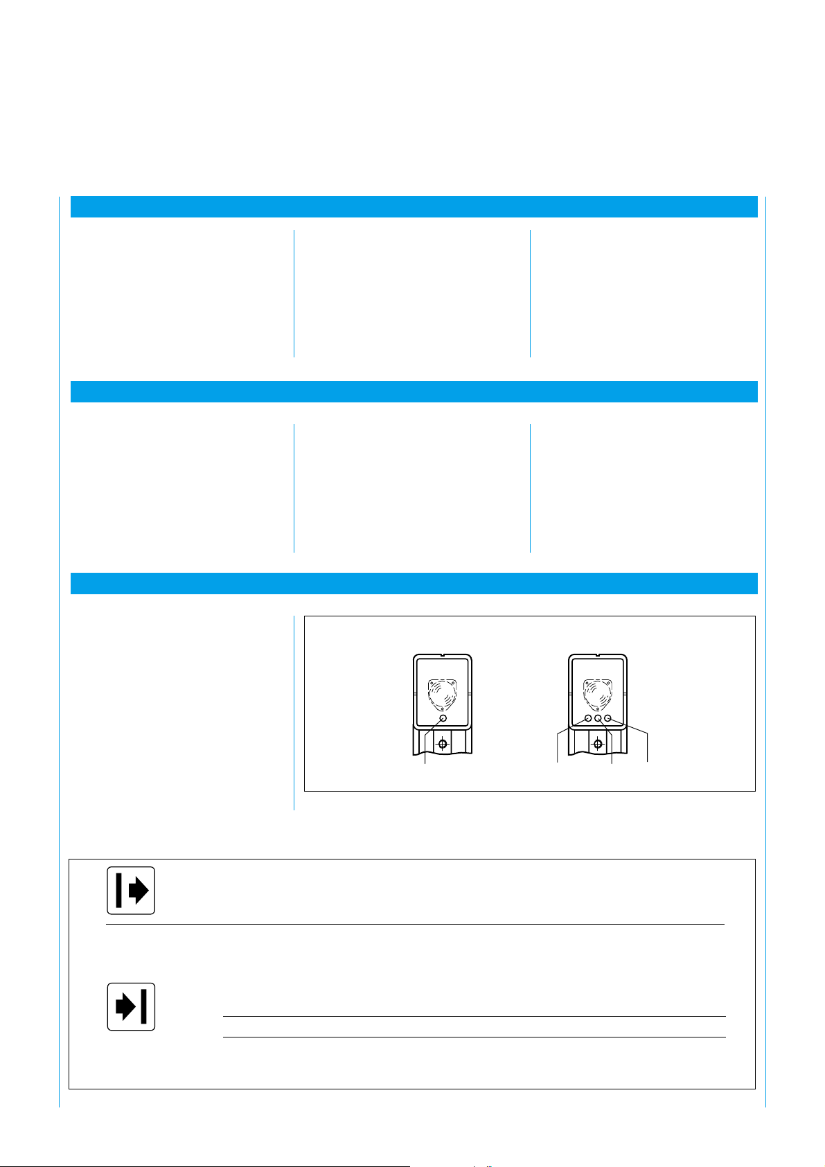
11.1 Diagnostic Elements
The LEDs on the WSU and WEU
indicate the following operating
states (Fig. 26):
‡ employees of SICK,
‡ employees of SICK subsidiaries
and representatives abroad,
WSU
yellow
Fig. 26: LEDs of the WSU and WEU
‡ employees of companies who
operate large quantities of SICK
safety equipment at their
premises, provided they have
been trained by SICK and have
been assigned by their
employers to perform such
duties.
WEU
green yellow red
Continuously lit yellow Operating voltage applied (test contact closed)
Off yellow No operating voltage applied or test active (For duration of test)
Continuously lit green Light beam of sender unit reaching receiver
yellow Sufficient light received
red Light beam broken, briefly during test
yellow + red Interference of another emitter element
Flashing yellow Insufficient light received, unit still functioning
Off green No operating voltage applied, light beam broken, test performed
yellow Light beam broken, testing performed, no operating voltage applied
red No operating voltage applied, light received from sender
Tab. 4: Functioning of the LEDs
8 008 692/9-12-99 Technical Description · WSU/WEU 26-2 © SICK AG · Safety Systems · Germany · All rights reserved
23
Page 24
Simple malfunctions can be rectified
by referring to the chart below.
Before opening up the units clean
the housing thoroughly to prevent
dirt entering the interior.
SICK WSU 26/2 – WEU 26/2
Do not touch any electrical connections when the unit is open
and switched on.
Fault
LED on WSU not lit
LED on WSU lit,
none of the three LEDs
on the WEU lit
The red LED on the WEU
is permanently lit
(no light being received)
The yellow LED on the WEU flashes
(insufficient light being received)
The yellow and red LEDs
on the WEU are permanently lit
Cause
No power supply
Break between terminals 10 and 11
(test contact)
No power supply on WEU
Break at relay contact
Relay defective
Unit out of alignment
Front screen dirty
Test input (sender) interrupted
Receiver WEU defective
Sender WSU not emitting
Sender WSU defective
Units or corner mirrors out of alignment
Front screen of WSU/WEU or corner
mirror dirty
Electronics activated:
Interference of another emitter element
Electronic card defective
Testing and remedy
Check voltage
Check passage
Check voltage on WEU
Replace unit
Re-align WSU and WEU units
Clean front screens of WSU and WEU
Check testing
Replace unit
On WSU briefly switch power off and
on again (min. 1 s)
Replace unit
Adjust units or corner mirrors to
optimum alignment
Clean front screen or corner mirror
On WEU briefly switch power off and
on again (min. 1 s)
WEU must only respond to the
corresponding WSU
Replace unit
.
24
8 008 692/9-12-99 Technical Description · WSU/WEU 26-2 © SICK AG · Safety Systems · Germany · All rights reserved
Page 25

SICK WSU 26/2 – WEU 26/2
12 Technical Data WSU 26/2 / WEU 26/2
Dimensions
Protective field range 0.5 ... 18 m, 15 ... 70 m
Number of beams 1 beam
Light beam diameter 23 mm
Sender/receiver unit
Supply voltage (Uv) 24 V DC ± 20 %
230 V DC ± 10 % / - 15 %
115 V DC ± 10 % / - 15 %
Ripple Max. 5 % of U
Frequency 48 ... 62 Hz with AC version
Input, sender Test contact
Test time max. 150 ms
Min. opening time of NC
contact for test 75 ms
Power consumption (typical)
Voltage version 24 V 115 V 230 V
Sender unit 4 W 7 W 7 W
Receiver unit 6 W 10 VA 10 VA
Synchronization Optical
Outputs Relay max. operating frequency 0.2 Hz
(1 operation in 5 s)
Switching current (max./min.) 2 A / 0.02 A
Switching voltage (max./min.) 250 V AC / 24 V DC
Response time ≤ 22 ms
Connection cable: PG connector: IP 67
Connection plug: IP 65
Front screen heating As standard
Operating data
Protection class I
Enclosure rating IP 65 (connection plug)
IP 67 (PG connector)
Safety category Satisfies type 4 requirements
Requirements To pr EN 61496 Part I/Part II
Ambient operating
temperature – 25 ... + 55 °C
Storage temperature – 25 ... + 70 °C
Air humidity 15 ... 95 %
Vibrostability 5 g, 10 ... 55 Hz to IEC 68-2-6
Impact resistance 10 g, 16 ms to IEC 68-2-29
Weight Sender unit Approx. 0.9 ... 1.3 kg
Receiver unit Approx. 1.0 ... 1.4 kg
V
12 Technical Data
8 008 692/9-12-99 Technical Description · WSU/WEU 26-2 © SICK AG · Safety Systems · Germany · All rights reserved
25
Page 26

13 Dimensional Drawing
13 Dimensional Drawing
SICK WSU 26/2 – WEU 26/2
50
65
156
65
14
PG13.5
Dimensional Drawing WSU 26/2-xx0 and WEU 26/2-xx0
34
17.5
128
15.5
116
65
95
96
26
8 008 692/9-12-99 Technical Description · WSU/WEU 26-2 © SICK AG · Safety Systems · Germany · All rights reserved
Page 27

SICK WSU 26/2 – WEU 26/2
156
65
65
14
50
34
128
15.5
65
95
96
116
81
50 mm
approx.
Dimensional Drawing WSU 26/2-xx4 and WEU 26/2-xx4
8 008 692/9-12-99 Technical Description · WSU/WEU 26-2 © SICK AG · Safety Systems · Germany · All rights reserved
27
Page 28

SICK WSU 26/2 – WEU 26/2
156
65
65
14
50
34
128
15.5
65
95
96
116
100
50 mm
approx.
Dimensional Drawing WSU 26/2-xx1 and -xx3 and WEU 26/2-xx1, -xx2 and -xx3
28
8 008 692/9-12-99 Technical Description · WSU/WEU 26-2 © SICK AG · Safety Systems · Germany · All rights reserved
Page 29

SICK WSU 26/2 – WEU 26/2
6.5
65
51
82
65
51
6.5
6
64.5
64.5
20°
46.5
39.5
60°
67
124
149
38
14
96
100
Corner mirror PSK 1
Order number 1 005 229
9
9
Mounting bracket
Order number 2 007 900
160
177
ø 7
8.5
2.5
10
20
26
40
43
22
M6
16.5
M 8x30 SW 13
M 8x45 SW 13
33.5
63
Bracket for corner mirror PSK 1
Order number 2 009 292
+0.2_
7
44.5
14
30
12
_
+0.5
190
160 Mirror length
+0,1
Ø 20
58
71
M6
+0.5
_
40.5
+1
_
95
Mirror width
105
_
+0.2
135
+2
156
Corner mirror PNS 105-1
Order number 1 004 076
76
40
40.5
8.5
Corner mirror PSK 45
Order number 5 306 053
146.5
80
96.5
45˚
8.5
69.5
Center of
mirror surface
63
8.5
80
Mounting set for PSK 1
Order number 2 012 473
8 008 692/9-12-99 Technical Description · WSU/WEU 26-2 © SICK AG · Safety Systems · Germany · All rights reserved
29
Page 30

50.5
SICK WSU 26/2 – WEU 26/2
119
4
Snow shield
65.5
65
12.3
7
3
Order number 1 003 619
50.5
65.565
73
4
11.8
140
Dust shield
Order number 1 003 556
30
8 008 692/9-12-99 Technical Description · WSU/WEU 26-2 © SICK AG · Safety Systems · Germany · All rights reserved
Page 31

SICK WSU 26/2 – WEU 26/2
14 At a glance: What is new about the WSU/WEU 26/2 in relation to the WSU/WEU 26?
Previously: WSU 26 / WEU 26
Now: WSU 26/2 / WEU 26/2
‡ The optical axis of the WSU/WEU
26/2 is shifted 6 mm toward the
device connection.
‡ There are two terminals for
connection of the power supply:
terminal 1/2 and terminal 3.
‡ Voltage versions
230 V AC
115 V AC
24 V DC
‡ A new adapter is required for
AR 60.
‡ No fiber-optic cable version is
available.
‡ An additional marking on the side
identifies the middle of the beam.
‡ The scanning ranges have changed:
WSU/WEU 26 WSU/WEU 26/2
0.5 ... 30 m 0.5 ... 18 m
30 ... 60 m 15 ... 70 m
For each range segment there is a
sender and a receiver.
‡ The beam diameter has changed:
WSU/WEU 26 WSU/WEU 26/2
33 mm 23 mm
‡ Connector version: the previous
connector no longer complies with
requirements for clearance and
creepage distances (VDE 0160 05/
88 and VDE 0110).
‡ New front screen: may only be
cleaned with plastic cleaner.
‡ The power consumption has
increased:
WSU/WEU 26 WSU/WEU 26/2 Version
5 VA / 7 VA 7 VA / 10 VA 115/230 V AC
3 W / 5 W 4 W / 6 W 24 V DC
‡ Response time
WSU/WEU 26: 20 ms
WSU/WEU 26/2: 22 ms
Components of the (new) WSU/
WEU 26/2 system cannot be
combined with components of the
(old) WSU/WEU 26 system. When
exchanging in the event of repair
please note that the following
combinations are not possible:
WSU 26 with WEU 26/2
WSU 26/2 with WEU 26
Exchange in pairs.
8 008 692/9-12-99 Technical Description · WSU/WEU 26-2 © SICK AG · Safety Systems · Germany · All rights reserved
31
Page 32

15 Selection Table
SICK WSU 26/2 – WEU 26/2
15 Selection Table WSU / WEU
Voltage Scanning Termination Sender unit Receiver unit
range type Type Order number Type Order number
230 V AC 0.5 ... 18 m PG WSU 26/2-110 1 015 615 WEU 26/2-110 1 015 616
Plug WSU 26/2-111 1 015 712 WEU 26/2-111 1 015 713
Plug *) WSU 26/2-113 1 015 715 WEU 26/2-113 1 015 715
Plug *) WEU 26/2-112 1 015 714
Plug 15 + PE*) WSU 26/2-114 1 015 834 WEU 26/2-114 1 015 835
15 ... 70 m PG WSU 26/2-210 1 015 731 WEU 26/2-210 1 015 743
Plug WSU 26/2-211 1 015 733 WEU 26/2-211 1 015 744
Plug *) WSU 26/2-213 1 015 736 WEU 26/2-213 1 015 748
Plug *) WEU 26/2-212 1 015 746
Plug 15 + PE*) WSU 26/2-214 1 015 840 WEU 26/2-214 1 015 841
115 V AC 0.5 ... 18 m PG WSU 26/2-120 1 015 717 WEU 26/2-120 1 015 718
Plug WSU 26/2-121 1 015 719 WEU 26/2-121 1 015 720
Plug *) WSU 26/2-123 1 015 723 WEU 26/2-123 1 015 722
Plug *) WEU 26/2-122 1 015 721
Plug 15 + PE*) WSU 26/2-124 1 015 836 WEU 26/2-124 1 015 837
15 ... 70 m PG WSU 26/2-220 1 015 738 WEU 26/2-220 1 015 749
Plug WSU 26/2-221 1 015 740 WEU 26/2-221 1 015 750
Plug *) WSU 26/2-223 1 015 737 WEU 26/2-223 1 015 505
WEU 26/2-222 1 015 751
Plug 15 + PE*) WSU 26/2-224 1 015 842 WEU 26/2-224 1 015 843
24 V DC 0.5 ... 18 m PG WSU 26/2-130 1 015 724 WEU 26/2-130 1 015 725
15 ... 70 m PG WSU 26/2-230 1 015 745 WEU 26/2-230 1 015 504
*) See electrical wiring diagram
Selection of plug variant,
WSU/WEU
Since 1989 VDE 0160 05/88 and
VDE 0110 have stipulated doubled
clearance and creepage distances. In
the following cases the necessary
clearance and creepage distances of
the 6-PE Hirschmann connecting
plug on the WEU are not met:
32
Plug WSU 26/2-131 1 015 726 WEU 26/2-131 1 015 727
Plug *) WSU 26/2-133 1 015 730 WEU 26/2-133 1 015 729
Plug *) WEU 26/2-132 1 015 728
Plug 15 + PE*) WSU 26/2-134 1 015 838 WEU 26/2-134 1 015 839
Plug WSU 26/2-231 1 015 747 WEU 26/2-231 1 015 753
Plug *) WSU 26/2-233 1 015 739 WEU 26/2-233 1 015 755
Plug *) WEU 26/2-232 1 015 754
Plug 15 + PE*) WSU 26/2-234 1 015 844 WEU 26/2-234 1 015 845
Supply voltage Voltage at WEU Remarks
WEU output relays
230 V AC 230 V AC Only in case of separated
circuits/phases (e.g. L1 to L2)
230 V AC 024 V DC –
024 V DC 230 V AC –
In order to meet the VDE requirements for clearance and creepage
distances in these cases, the square 15-pin + PE plug must be used.
8 008 692/9-12-99 Technical Description · WSU/WEU 26-2 © SICK AG · Safety Systems · Germany · All rights reserved
Page 33

SICK WSU 26/2 – WEU 26/2
14.1 Conversion List
WSU to be Nex type 26/2
replaced Scanning range 0.5 ... 18 m Scanning range 15 ... 70 m
WSU 26-110 WSU 26/2-110 1 015 615 WSU 26/2-210 1 015 731
WSU 26-111 WSU 26/2-111 1 015 712 WSU 26/2-211 1 015 733
WSU 26-112 WSU 26/2-113 1 015 716 WSU 26/2-213 1 015 736
WSU 26-120 WSU 26/2-120 1 015 717 WSU 26/2-220 1 015 738
WSU 26-121 WSU 26/2-121 1 015 719 WSU 26/2-221 1 015 740
WSU 26-130 WSU 26/2-130 1 015 724 WSU 26/2-230 1 015 745
WSU 26-131 WSU 26/2-131 1 015 726 WSU 26/2-231 1 015 747
WSU 26-132 WSU 26/2-133 1 015 730 WSU 26/2-233 1 015 739
WSU 26-210 WSU 26/2-210 1 015 731
WSU 26-211 WSU 26/2-211 1 015 733
WSU 26-212 WSU 26/2-213 1 015 736
WSU 26-220 WSU 26/2-220 1 015 738
WSU 26-221 WSU 26/2-221 1 015 740
WSU 26-230 WSU 26/2-230 1 015 745
WSU 26-231 WSU 26/2-231 1 015 747
WSU 26-232 WSU 26/2-233 1 015 739
old
WEU to be New type 26/2
replaced Scanning range 0.5 ... 18 m Scanning range 15 ... 70 m
WEU 26-710 WEU 26/2-110 1 015 616 WEU 26/2-210 1 015 743
WEU 26-712 WEU 26/2-112 1 015 713 WEU 26/2-211 1 015 744
WEU 26-713 WEU 26/2-113 1 015 715 WEU 26/2-213 1 015 748
WEU 26-720 WEU 26/2-120 1 015 718 WEU 26/2-220 1 015 749
WEU 26-730 WEU 26/2-130 1 015 725 WEU 26/2-230 1 015 504
WEU 26-731 WEU 26/2-131 1 015 727 WEU 26/2-231 1 015 753
WEU 26-732 WEU 26/2-132 1 015 728 WEU 26/2-232 1 015 754
WEU 26-733 WSU 26/2-133 1 015 729 WEU 26/2-233 1 015 755
old
8 008 692/9-12-99 Technical Description · WSU/WEU 26-2 © SICK AG · Safety Systems · Germany · All rights reserved
33
Page 34

16 Selection Table, Accessories
16 Selection Table, Accessories
Description Order number
Alignment aid AR 60, complete 1 015 741
Adapter for alignment aid AR 60 4 031 156
Mounting bracket for WSU/WEU 2 007 900
Corner mirror PSK 1, for scanning range 0.5 ... 18 m 1 005 229
Mounting set for PSK 1 2 012 473
Hinged bracket for corner mirror PSK 1 (x 1) 2 009 292
Corner mirror PNS 105-1, for scanning range 15 ... 70 m 1 004 076
Corner mirror PSK 45 5 306 053
Cable receptacle, straight, 6 + PE (plastic) 6 006 612
Cable receptacle, angled, 6 + PE (plastic) 6 006 613
Cable receptacle, 15 + PE, lateral cable outlet, PG 16 2 019 076
Cable receptacle, 15 + PE, straight cable outlet, PG 13.5 2 019 075
Arc-suppression element 0.22 µF + 220 Ω (115 ... 230 V) 6 001 224
Arc-suppression element 2.2 µF + 100 Ω (24 V) 6 001 225
Switching amplifier LCU-X 24 V DC 1 013 410
Switching amplifier (PILZ)
Switching amplifier PST 1 24 V DC 6 010 808
230 V AC 6 010 809
SICK WSU 26/2 – WEU 26/2
Switching amplifier PST 3 24 V DC 6 008 424
Switching amplifier PNOZ 8 24 V DC 6 010 810
PG cable gland PG 21 5 305 978
for use of 2 cables with PNOZ 8
PG extension PG 13.5 to PG 21 5 306 052
for use of 2 cables with PNOZ 8
230 V AC 6 008 423
230 V AC 6 010 811
34
8 008 692/9-12-99 Technical Description · WSU/WEU 26-2 © SICK AG · Safety Systems · Germany · All rights reserved
Page 35

SICK AG · Safety Systems · P.O. Box 310 · D-79177 Waldkirch
Phone +49 76 81/2 02-0 · Fax +49 76 81/2 02-38 15 · http://www.sick.de
8 008 692/9-12-99 · KF · KF · Printed in Germany (1299)
·
Subject to change without prior notice
E 2.02
Your contacts:
Australia
Phone +61/3 94 97 4100
008/33 4802 – toll free
Fax +61/3 94 9711 87
Austria
Phone +43/2 23 66 2288-0
Fax +43/2 23 6622 88-5
Belgium/Luxembourg
Phone +32/24 66 55 66
Fax +32/24 66 6026
Brazil
Phone +55 11/55 61 2683
Fax +5511/5354153
China/Hong Kong
Phone +8 52/27 63 6966
Fax +8 52/27 6363 11
Czech Republik
Phone +42 /02 578 10561
Fax +42 /02 57810 559
Denmark
Phone +45/45 82 64 00
Fax +45/45 82 6401
Finland
Phone +3 58/9-728 85 00
Fax +3 58/9-72 88 50 55
France
Phone +33/1-64 62 35 00
Fax +33/1-64 62 3577
Germany
Phone +49 7681/2 02-0
Fax +49 76 81/2 02-3815
Great Britain
Phone +44/17 27-83 11 21
Fax +44/17 27-85 6767
Italy
Phone +3 90/2-92 14 20 62
Fax +3 90/2-92 14 20 67
Japan
Phone +8 13/33 58-13 41
Fax +8 13/33 58-05 86
Netherlands
Phone +31/30 229 25 44
Fax +31/30 229 39 94
Norway
Phone +47/67 56 75 00
Fax +47/67 56 6610
Poland
Phone +48/2 26 44 8345
Fax +48/2 26 4483 42
Singapore
Phone +65/7 44 37 32
Fax +65/8 41 7747
Spain
Phone +34/93 4 80 3100
Fax +34/93 4 7344 69
Sweden
Phone +46/8-6 80 64 50
Fax +46/8-7 10 1875
Switzerland
Phone +41/4 16 19 2939
Fax +41/4 16 1929 21
Taiwan
Phone +88 62/23 65 6292
Fax +88 62/23 6873 97
USA
Phone +16 12/9 41-67 80
Fax +16 12/9 41-9287
Representatives and agencies
in all major industrial nations.
 Loading...