

Page 1
WI180C-EC
WI180C-EC EtherCAT coupler
O P E R A T I N G I N S T R U C T I O N
Page 2

Described product
2006/42/EC
NO
SAFETY
WI180C-EC
Manufacturer
SICK AG
Erwin-Sick-Str. 1
79183 Waldkirch
Germany
Legal information
This work is protected by copyright. Any rights derived from the copyright shall be
reserved for SICK AG. Reproduction of this document or parts of this document is only
permissible within the limits of the legal determination of Copyright Law. Any modifica‐
tion, abridgment or translation of this document is prohibited without the express writ‐
ten permission of SICK AG.
The trademarks stated in this document are the property of their respective owner.
© SICK AG. All rights reserved.
Original document
This document is an original document of SICK AG.
2
O PE R AT I NG IN S TR U CT I ON | WI180C-EC 8024001/2019-05-27 | SICK
Subject to change without notice
Page 3

Contents
CONTENTS
1 About this document........................................................................ 5
1.1 Purpose of this document........................................................................ 5
1.2 Target group.............................................................................................. 5
1.3 Information depth..................................................................................... 5
1.4 Explanation of symbols............................................................................ 5
1.5 Product information.................................................................................. 6
1.6 Further information................................................................................... 6
2 Safety information............................................................................ 7
2.1 General safety notes................................................................................ 7
2.2 Correct use................................................................................................ 7
2.3 Forseeable misuse................................................................................... 7
3 Product description........................................................................... 8
3.1 Product characteristics............................................................................ 8
3.2 Setup and function................................................................................... 8
3.3 Interfaces.................................................................................................. 8
3.3.1 EtherCAT................................................................................... 8
3.3.2 Power supply............................................................................ 9
3.3.3 Grounding................................................................................. 9
4 Transport and storage....................................................................... 10
4.1 Transport................................................................................................... 10
4.2 Storage...................................................................................................... 10
5 Mounting............................................................................................. 11
5.1 Required materials................................................................................... 11
5.2 Preparing mounting location.................................................................... 11
5.3 Scope of delivery....................................................................................... 11
5.4 Mounting procedure................................................................................. 11
5.5 Connecting the device.............................................................................. 12
6 Commissioning.................................................................................. 13
6.1 Parameterization....................................................................................... 13
6.2 Switching on.............................................................................................. 13
7 Operation............................................................................................ 14
7.1 Safety......................................................................................................... 14
7.2 Daily thorough check................................................................................ 14
7.3 LED status indicators............................................................................... 14
7.4 Device slots and modules........................................................................ 15
7.5 Cyclic data (process data)........................................................................ 16
7.6 Acyclic data (service data)........................................................................ 17
7.7 Object library............................................................................................. 17
7.7.1 Standard objects..................................................................... 18
8024001/2019-05-27 | SICK O P ER A TI N G I NS T RU C TI O N | WI180C-EC
Subject to change without notice
3
Page 4

CONTENTS
7.7.2 Module data............................................................................. 20
7.7.3 Coupler data............................................................................. 21
7.7.4 WLL180T.................................................................................. 23
7.7.5 KTL180..................................................................................... 25
7.7.6 OD1 on AOD1........................................................................... 27
7.7.7 OL1 on AOD1............................................................................ 31
8 Diagnosis............................................................................................ 35
9 Decommissioning............................................................................. 36
9.1 Dismantling............................................................................................... 36
9.2 Disposal..................................................................................................... 36
10 Technical data.................................................................................... 37
10.1 Dimensional drawings.............................................................................. 37
10.2 Technical data........................................................................................... 37
10.3 UL Satisfaction Ratings............................................................................ 39
10.4 Ordering information, accessories........................................................... 39
4
O PE R AT I NG IN S TR U CT I ON | WI180C-EC 8024001/2019-05-27 | SICK
Subject to change without notice
Page 5

1 About this document
1.1 Purpose of this document
These operating instructions contain information required during the life cycle of the
device.
These operating instructions must be made available to all those who work with the
device.
Please read these operating instructions carefully and make sure that you understand
the content fully before working with the device.
1.2 Target group
These operating instructions are intended for the following target groups: Project devel‐
opers (planners, developers, designers), installers, electricians, programmers, opera‐
tors and maintenance personnel.
The structure of these operating instructions is based on the life-cycle phases of the
device: Project planning, mounting, electrical installation, commissioning, operation,
maintenance and disposal.
ABOUT THIS DOCUMENT 1
1.3 Information depth
These operating instructions contain information about the following topics relating to
the device:
Product description
•
Mounting
•
Electrical installation
•
Commissioning and configuration
•
Furthermore, when planning and using sensors such as the device, technical expertise
is required, which is not covered in this document.
Official and legal regulations for operating the device volume measurement system
must always be complied with.
You can find further information on the Internet at www.sick.com.
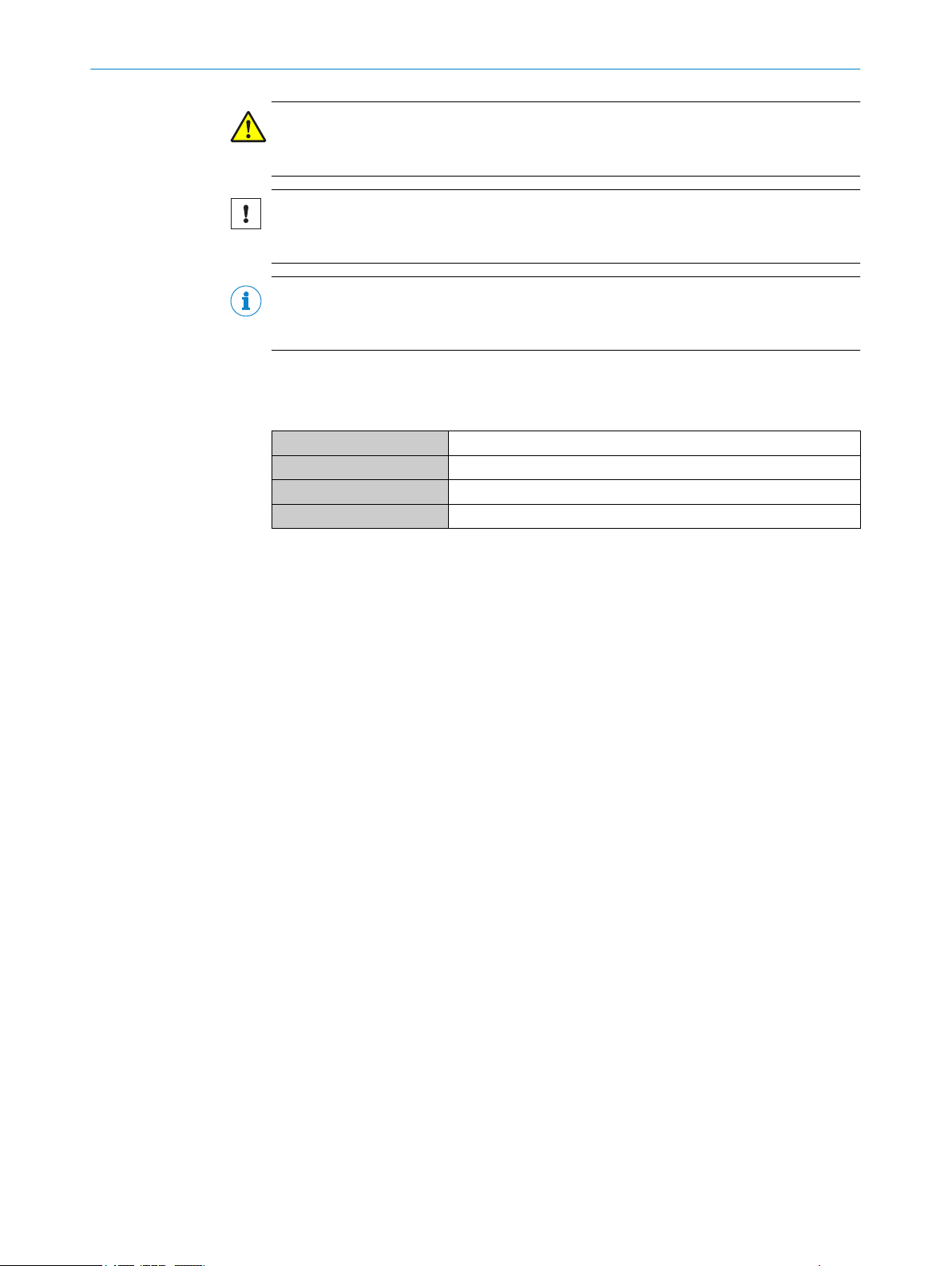
1.4 Explanation of symbols
Warnings and important information in this document are labeled with symbols. The
warnings are introduced by signal words that indicate the extent of the danger. These
warnings must be observed at all times and care must be taken to avoid accidents, per‐
sonal injury, and material damage.
DANGER
… indicates a situation of imminent danger, which will lead to a fatality or serious
injuries if not prevented.
WARNING
… indicates a potentially dangerous situation, which may lead to a fatality or serious
injuries if not prevented.
8024001/2019-05-27 | SICK O P ER A TI N G I NS T RU C TI O N | WI180C-EC
Subject to change without notice
5
Page 6
1 ABOUT THIS DOCUMENT
CAUTION
… indicates a potentially dangerous situation, which may lead to minor/slight injuries if
not prevented.
NOTICE
… indicates a potentially harmful situation, which may lead to material damage if not
prevented.
NOTE
… highlights useful tips and recommendations as well as information for efficient and
trouble-free operation.
1.5 Product information
Table 1: Product information
Product name WI180C-EC
Article number 6068089
Device version EtherCAT
Manufacturer SICK AG
1.6 Further information
www.sick.com
The following information is available on the Internet:
Other language versions
•
Data sheets and application examples
•
CAD data of drawings and dimensional drawings
•
Certificates (e.g. EU declaration of conformity)
•
Current device files
•
6
O PE R AT I NG IN S TR U CT I ON | WI180C-EC 8024001/2019-05-27 | SICK
Subject to change without notice
Page 7

2 Safety information
2.1 General safety notes
The mounting, electrical installation and configuration of the device must be car‐
•
ried out by professionally qualified personnel only.
Before mounting, it is imperative that you familiarize yourself with the operating
•
instructions for the connected devices.
When mounting and electrical installation work is being carried out, always comply
•
with applicable health and safety and environmental regulations.
The device must not be used outdoors or in areas with flammable/explosive
•
atmospheres!
When installing the device, always consider the electrical connected loads.
•
Replace faulty or damaged cables and male connectors immediately.
•
Replace damaged or faulty couplers immediately.
•
When mounting the device, it is imperative that you use suitable mounting equip‐
•
ment and that you consider their specific requirements.
Ensure a constant power supply to the device within the set parameters.
•
Only operate the device within the set operating parameters.
•
Regularly check that the device is functioning properly.
•
Structural modifications to the device are not permitted.
•
The device is not designed as a safety product.
•
This device complies with the Radio Safety Requirements (EMC) for the industrial
•
sector (Radio Safety Class A). It may cause radio interference if used in a residen‐
tial area.
SAFETY INFORMATION 2
2.2 Correct use
Correct use requires that the device is used industrially indoors without any specific cli‐
matic and atmospheric requirements. Any use outside of the areas mentioned in each
case will be considered to be incorrect use and void any warranty claims against
SICK AG.
2.3 Forseeable misuse
Not taking account of the pin assignment or using an incorrect adapter cable may dam‐
age or destroy the connected EtherCAT coupler.
Connecting the EtherCAT coupler to signal or power cables that are too long may lead to
a loss of data and damage to the EtherCAT coupler.
8024001/2019-05-27 | SICK O P ER A TI N G I NS T RU C TI O N | WI180C-EC
Subject to change without notice
7
Page 8
1
2
3
6
5
4
1
43
2
3 PRODUCT DESCRIPTION
3 Product description
3.1 Product characteristics
The device is an interface coupler that can be used to connect connected devices (e.g.
WLL180T) to the EtherCAT network. The relevant devices are connected via a simple
plug system on the side of the coupler.
Normally the entire system is installed on a mounting rail near the application.
The coupler supports up to 16 connected devices, which are likewise connected to one
another via the plug system.
Further properties:
EtherCAT slave
•
Configuration via CoE protocol (CANopen over EtherCAT)
•
2 Ethernet connections with transmission rate of 100 Mbaud
•
Further specifications can be found in the technical data (see "Technical data",
page 37).
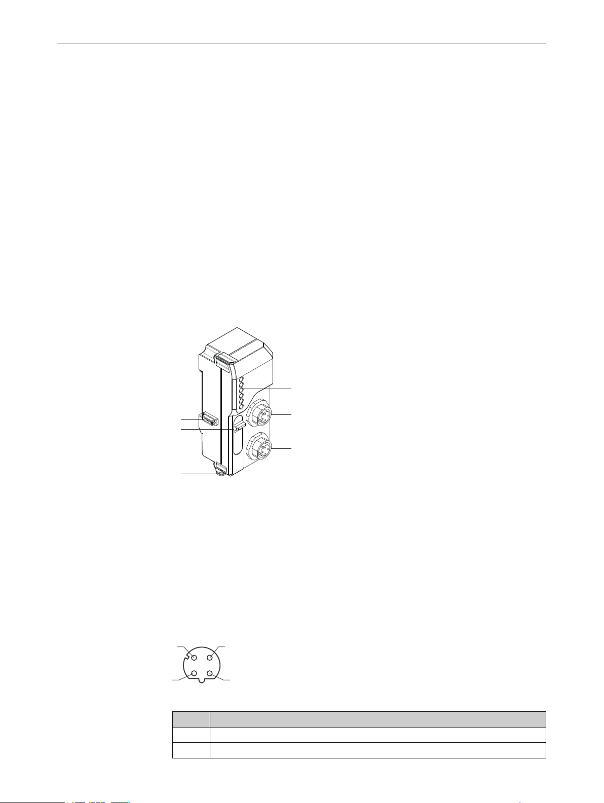
3.2 Setup and function
Bus male connector (system bus)
1
Service port
2
Power supply connection (M8), 4-pin
3
D-coded M12 connector, 4-pin, EtherCAT
4
D-coded M12 connector, 4-pin, EtherCAT
5
Status LEDs
6
3.3 Interfaces
3.3.1 EtherCAT
8
O PE R AT I NG IN S TR U CT I ON | WI180C-EC 8024001/2019-05-27 | SICK
Table 2: EtherCAT pin assignment
Pin Pin assignment
1 Tx+
2 Rx+
Subject to change without notice
Page 9
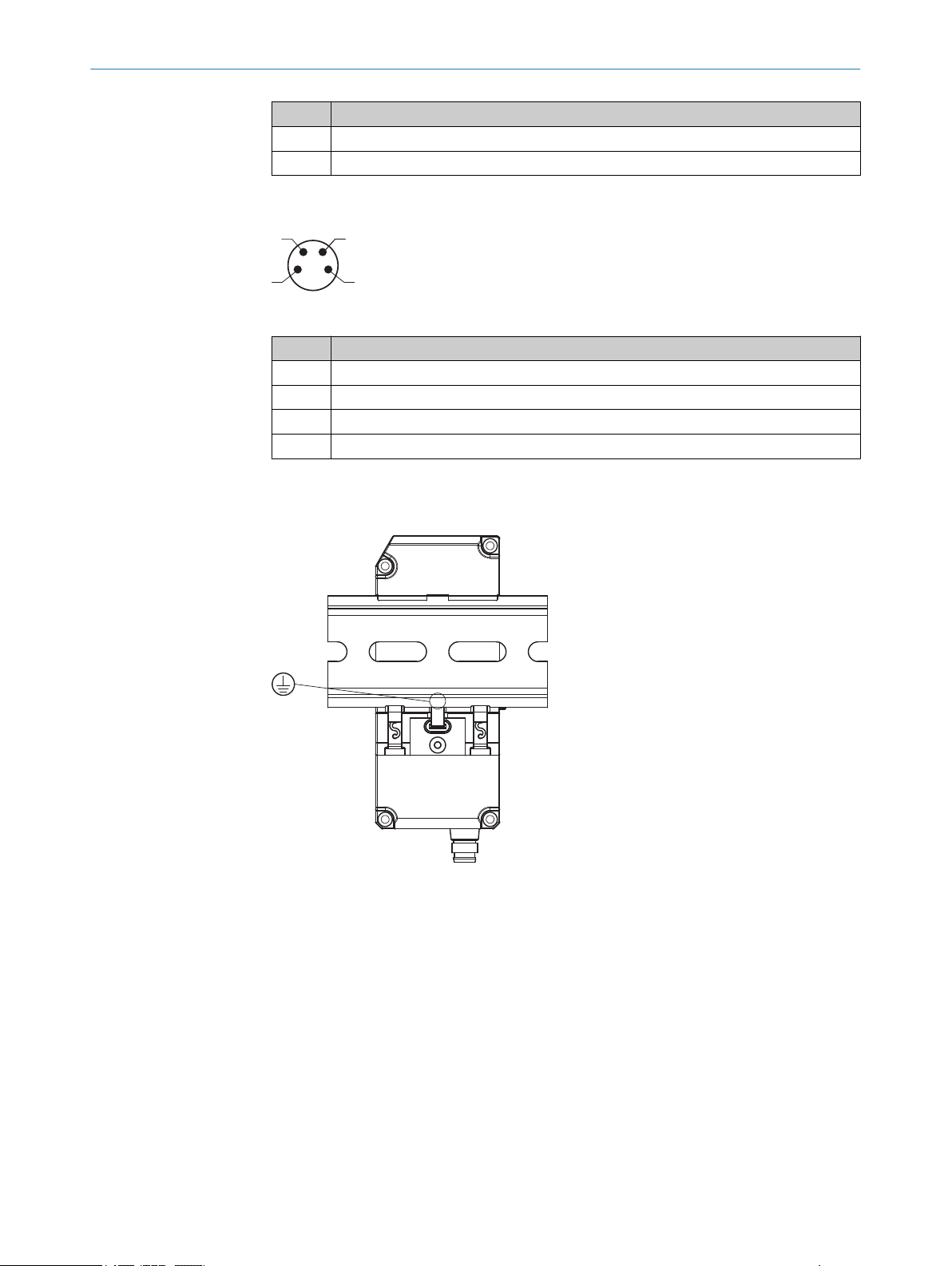
3.3.2 Power supply
2 4
1
3
3.3.3 Grounding
PRODUCT DESCRIPTION 3
Pin Pin assignment
3 Tx-
4 Rx-
Table 3: Power supply pin assignment
Pin Pin assignment
1 +12 – 24 VDC
2 Not assigned
3 GND
4 Not assigned
The device is grounded via the mounting rail by means of a spring contact:
8024001/2019-05-27 | SICK O P ER A TI N G I NS T RU C TI O N | WI180C-EC
Subject to change without notice
9
Page 10

4 TRANSPORT AND STORAGE
4 Transport and storage
4.1 Transport
Either transport the device in the original packaging or use a padded transport con‐
tainer. Make sure that you comply with the maximum permitted environmental condi‐
tions (see "Technical data", page 37).
4.2 Storage
If you want to store the devicefor a relatively long time, pack it as you would for trans‐
port. Make sure that the storage location complies with the permitted environmental
conditions (see "Technical data", page 37).
10
O PE R AT I NG IN S TR U CT I ON | WI180C-EC 8024001/2019-05-27 | SICK
Subject to change without notice
Page 11
5 Mounting
1
2
5.1 Required materials
You need the following additional materials to mount the device:
grounded mounting rail (pre-mounted)
•
pre-assembled cable (max. 30 m) with M8 female connector (see "Interfaces",
•
page 8)
pre-assembled cable for EtherCAT with M12 D-coded male connector (see "Inter‐
•
faces", page 8)
one or more signal sources (e.g. WLL180T)
•
small slotted screwdriver
•
MOUNTING 5
5.2
Preparing mounting location
1. Mount a grounded mounting rail in the same area as the application.
2. Lay the two pre-assembled cables so that they can easily be connected to the con‐
nections of the device. If necessary, use cable channels, cable ties and cable
grips.
5.3 Scope of delivery
WI180C-EC
•
Quick start instructions
•
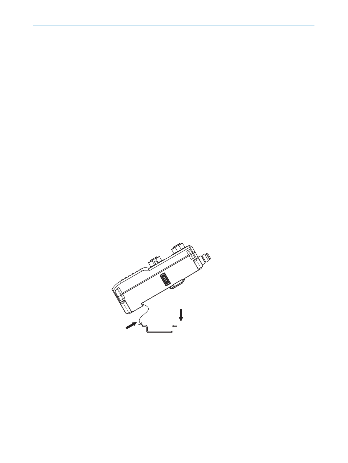
5.4 Mounting procedure
1. Carefully unpack the device.
2. Clamp the device onto the mounting rail, as shown in the image.
3. Clamp the series-connected devices onto the mounting rail as shown in their
mounting instructions.
8024001/2019-05-27 | SICK O P ER A TI N G I NS T RU C TI O N | WI180C-EC
Subject to change without notice
11
Page 12
5 MOUNTING
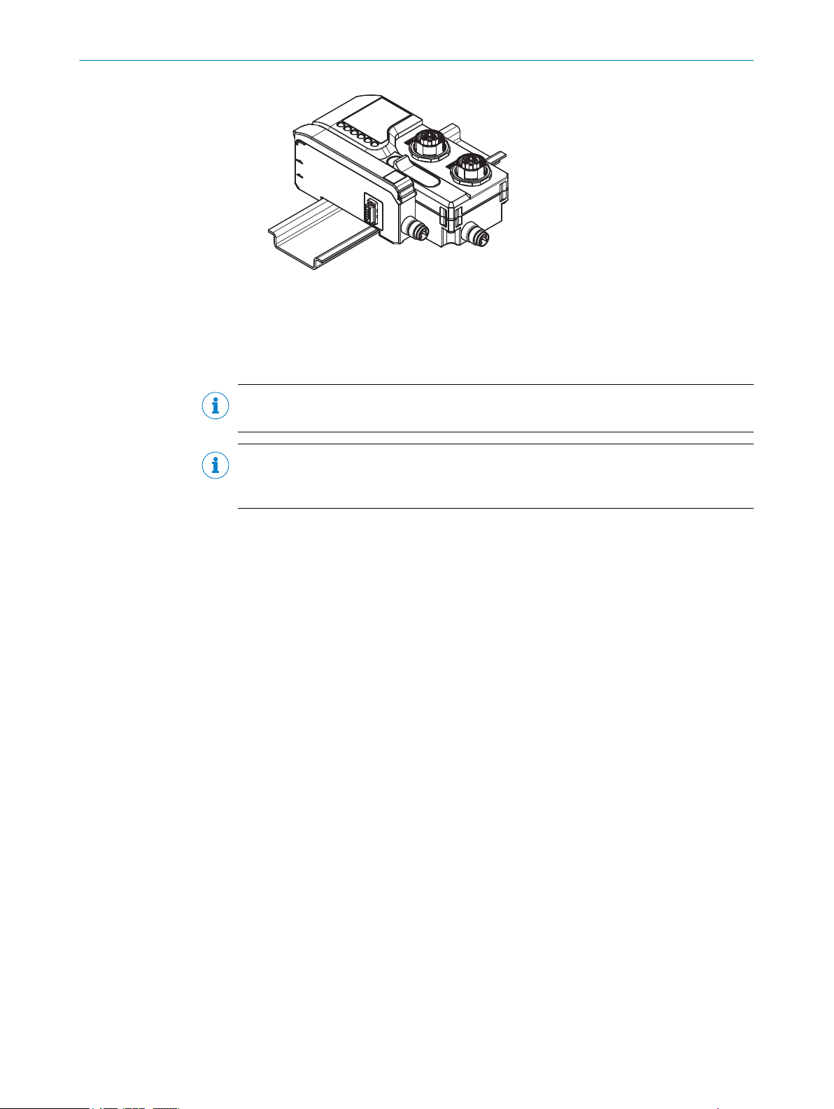
4. Push the series-connected devices onto the 5-pin connection on the left side of
the device. Make sure that the sequence is correct.
5. Fix the connected devices on the mounting rail without any spaces.
5.5 Connecting the device
NOTE
Switch off the voltage supply before you connect or replace the devices.
NOTE
Select the right EtherCAT connection for your network. Connection 1 has the function of
the “EtherCAT IN port”, connection 2 has the function of the “EtherCAT OUT port”.
1. Connect the D-coded M12 male connector for the EtherCAT network to the Ether‐
CAT connection on the device, and fasten it with the coupling nut.
2. Connect the M8 female connector to the voltage supply on the bottom of the
device and tighten the corresponding male connector.
1)
1)
see the operating instructions for the relevant device
12
O PE R AT I NG IN S TR U CT I ON | WI180C-EC 8024001/2019-05-27 | SICK
Subject to change without notice
Page 13

6 Commissioning
6.1 Parameterization
The WI180C-EC can be integrated in a Beckhoff control system. An ESI file is loaded in
the system for this purpose. The ESI file for the WI180C-EC is available for download
from www.sick.de.
NOTE
All configuration information relates to controls manufactured by Beckhoff, which are
configured and diagnosed with the TwinCAT™ configuration tool.
1. Copy the ESI file in the TwinCAT™ directory into the TwinCAT\3.1\Config\IO\Ether‐
CAT folder.
2. Then restart the TwinCAT™ system manager.
3. Insert WI180C-EC into the device tree as a box.
4. For this purpose, select the WI180C-EC under SICK AG.
The WI180C-EC is shown in the device tree as box n.
5. Then switch the TwinCAT™ system manager to configuration mode.
You will be asked in sequence whether the TwinCAT system manager™ should be
switched to configuration mode, whether the data should be loaded from the I/O
device, and whether the system should be switched to Free Run operating mode.
6. Click OK or Yes in each instance.
The status display at the bottom right changes between Free Run in red and Config
Mode in blue. All object parameters can now be read out and configured on the
CoE - Online tab.
COMMISSIONING 6
6.2 Switching on
1. Switch on the power supply for the device.
2. Wait approximately two seconds until the device indicates that it is ready, see "LED
status indicators", page 14.
8024001/2019-05-27 | SICK O P ER A TI N G I NS T RU C TI O N | WI180C-EC
Subject to change without notice
13
Page 14

1
2
3
4
5
6
7 OPERATION
7 Operation
7.1 Safety
A few guidelines must be followed to ensure the operational safety of the device:
Carry out a daily functional check (see "Daily thorough check", page 14).
•
If you want to connect devices to the device or remove devices, switch off the
•
power supply first.
Only operate the WI180C-EC under the specified operating conditions (see "Tech‐
•
nical data", page 37).
7.2 Daily thorough check
You should carry out the following functional checks once a day:
Check the function of the LED indicators.
•
Use appropriate status queries to check communication with each of the con‐
•
nected devices.
7.3 LED status indicators
14
Table 4: LED status indicators
LED Display Meaning
PWR Green
1
ERR (error) Red
2
RUN (operation) Green
3
STATUS Green
4
O PE R AT I NG IN S TR U CT I ON | WI180C-EC 8024001/2019-05-27 | SICK
O
o
o
Single flash Local error in the device
Double flash Timeout in the device
O
Ö
o
O
Ö
o
O
Voltage supply on
Voltage supply off
No error
Application controller fault
Invalid configuration
Device initializes
Device has OPERATIONAL status
Device has PRE-OPERATIONAL status
Device not configured
Device is running
Subject to change without notice
Page 15

LED Display Meaning
1 2 3 16
L/A1 (Link/Activ‐
5
ity 1)
L/A2 (Link/Activ‐
6
ity 2)
7.4 Device slots and modules
WI180C-EC uses the EtherCAT “Modular Device Profile” (MDP) and every connected
device occupies one or more module slots.
The module slots 1 to 16 represent the connected devices, as shown in the figure
below.
Green
Green
o
O
Ö
o
O
Ö
OPERATION 7
No network connection at connection 1
Network connection at connection 1 avail‐
able, no communication
Network connection, communication
active
No network connection at connection 2
Network connection at connection 2 avail‐
able, no communication
Network connection, communication
active
8024001/2019-05-27 | SICK O P ER A TI N G I NS T RU C TI O N | WI180C-EC
Subject to change without notice
The WI180C-EC supports up to 16 device modules. The following products are sup‐
ported:
Table 5: Supported products
Supported products Product description Note
WLL180T-L*
WLL180T-M*
WLL180T-E*
WLL180T-F*
Fiber amplifier basic device
Fiber amplifier expansion
module
The WLL180T basic device
•
can be installed only as
Module 1 (on the far out‐
side left of the mounting
rail)
No additional voltage supply
•
is required for the WLL180T
device
The WLL180T basic device
•
can be installed only as
Module 2 to Module 16
No additional voltage supply
•
is required for the WLL180T
device
15
Page 16

7 OPERATION
Supported products Product description Note
OD1 at one input of AOD1-M Displacement sensor
Evaluation unit basic device
OL1 at one input of AOD1-M Displacement sensor
Evaluation unit basic device
•
•
•
•
OD1 at one input of AOD1-S Displacement sensor
Evaluation unit expansion
module
OL1 at one input of AOD1-S Displacement sensor
Evaluation unit expansion
module
•
•
•
•
KTL180-ML*
KTL180-MM*
Fiber contrast sensor basic
device
•
•
KTL180-ME*
KTL180-MF*
Fiber contrast sensor expan‐
sion module
•
•
For each AOD1 unit con‐
nected, the number of plug‐
gable modules decreases
by one (max. 8 AOD1
devices possible)
If AOD1 and WLL180T are
used in combination with
WI180C-EC, all WLL180T
devices must be placed on
the left of AOD1
The AOD1-M basic device
can be installed only as
Module 1/2 (on the far out‐
side left of the mounting
rail)
Voltage supply required for
the AOD1-M device
For each AOD1 unit con‐
nected, the number of plug‐
gable modules decreases
by one (max. 8 AOD1
devices possible)
If AOD1 and WLL180T are
used in combination with
WI180C-EC, all WLL180T
devices must be placed on
the left of AOD1
The AOD1-S expansion
module can be installed
only as Module 3/4 to Mod‐
ule 15/16
Voltage supply required for
the AOD1-S device
The KTL180 basic device
can be installed only as
Module 1 (on the far out‐
side left of the mounting
rail)
No additional voltage supply
is required for the KTL180
device
The KTL180 expansion
module can be installed
only as Module 2 to Mod‐
ule 16
No additional voltage supply
is required for the KTL180
device
7.5 Cyclic data (process data)
WI180C-EC supports both “Transmit PDOs” (WI180C-EC to control) and “Receive PDOs"
(control to WI180C-EC). The PDOs are permanently implemented in the WI180C-EC and
it is not possible to map any other objects than the predefined objects. The minimum
PDO cycle time is 1000 µs.
16
O PE R AT I NG IN S TR U CT I ON | WI180C-EC 8024001/2019-05-27 | SICK
Subject to change without notice
Page 17

7.6 Acyclic data (service data)
WI180C-EC supports the “CANopen over EtherCAT” (CoE) protocol for transmission of
service data. Service data objects (SDO) form the communication channel through
which device parameters are transmitted (e.g. programming switching thresholds).
Transmission of these parameters to SDOs is acyclic (i.e. takes place just once when
starting up the network). The objects of the object library (see "Object library",
page 17) can be accessed with the SDOs.
NOTE
It is possible to access the device parameters of every connected device via SDOs. The
specific addressing for each module depends on which modules were configured in the
control software.
7.7 Object library
The WI180C-EC device is structured according to the EtherCAT “Modular Device Profile”
(MDP). Objects are correspondingly available in the following address ranges:
Index range Use
0x1000 ...
0x1FFF
0x6000 ...
0x6FFF
0x7000 ...
0x7FFF
0x8000 ...
0x8FFF
0x9000 ...
0x9FFF
0xA000 ...
0xAFFF
0xF000 ...
0xFFFF
Standard communication objects
Input process data of connected modules
Output process data of connected modules
Configuration data of connected modules
Identification data of connected modules
Diagnostic data of connected modules
Data of the EtherCAT coupler WI180C-EC
OPERATION
7
NOTE
16 unique data record addresses are available for each module in the address ranges
0x6... / 0x7... / 0x8... / 0x9... / 0xA:
- Slot 1, sensor 1 (outside far left)
Data records
0x6000...0x600F / 0x7000...0x700F / 0x8000...0x800F / 0x9000...0x900F / 0xA000
...0xA00F
- Slot 2, sensor 2
Data records
0x6010...0x601F / 0x7010...0x701F / 0x8010...0x801F / 0x9010...0x901F / 0xA010
...0xA01F
- ...
- Slot 16, sensor 16
Data records
0x60F0...0x60FF / 0x70F0...0x70FF / 0x80F0...0x80FF / 0x90F0...0x90FF / 0xA0F0...
0xA0FF
The available objects are listed below. The following abbreviations apply:
8024001/2019-05-27 | SICK O P ER A TI N G I NS T RU C TI O N | WI180C-EC
Subject to change without notice
17
Page 18

7 OPERATION
Abbreviation Meaning
R Read only access
R/W Read/write access
STRG String = a chain of characters of varying length
BOOL Boolean = logical value 0 or 1
ENUM Freely selectable values with a limited value range (e.g. BLACK, RED, BLUE,
YELLOW)
INT Signed Integer = whole number value with sign (e.g. INT-32 =
-2.147.483.648 ... 2.147.483.647)
UINT Unsigned Integer = whole number value (e.g. UINT-32 = 0 ...
4.294.967.295)
ARRAY Data sequence of a data type (e.g. Array UINT-8 = character string of the
data type UINT-8)
RECORD Sequence of data containing different data types (e.g. UINT-8, UINT-32,
UINT-32, UINT-16)
STRUCT Sequence of data containing different data types (e.g. UINT-8, UINT-32,
UINT-32, UINT-16)
7.7.1 Standard objects
Table 6: Standard objects
Detailed descrip‐
Object Function
tion
0x1000 Device type - R UINT-32 EtherCAT device type: 0x00001389, corre‐
0x1008 Device name - R STRG Type code
0x1009 Hardware version number - R STRG Hardware revision status
0x100A Software version number - R STRG Firmware revision status
0x1018 Identity Subindex, data
type
.00, UINT-8
.01, UINT-32
.02, UINT-32
.03, UINT-32
.04, UINT-32
0x10F3 Diagnostics history Subindex, data
type
.00, UINT-8
.01, UINT-8
.02, UINT-8
.03, UINT-8
.04, BOOL
.05, UINT-16
.06…xx, ARRAY
UINT-8
0x1600…
0x160F
Receive PDOs modules
(0x70n0)
Subindex, data
type
.00, UINT-8
.01, UINT-32
.02, UINT-32
Acc
ess Data type Content/meaning
sponding to Modular Device Profile
R RECORD EtherCAT identification values
Subindex 00 = Number of subindices
Subindex 01 = Vendor ID (SICK AG)
Subindex 02 = Product code
Subindex 03 = Revision number (Firmware
version)
Subindex 04 = Serial number
R RECORD Error history
Subindex 00 = Number of subindices
Subindex 01 = Max. number of stored
diagnostic messages (from subindex 06)
Subindex 02 = Subindex of the latest diag‐
nostic message
Subindex 03 = Latest confirmed diagnostic
message
Subindex 04 =New diagnostic message
present
Subindex 05 = Flags for transmission and
storage of diagnostic messages
Subindex 06...xx = Diagnostic messages
R RECORD Receive PDOs of the connected modules
Subindex 00 = Number of subindices
Subindex 01 = Object 0x70n0.01, Teach
Request
Subindex 02 = Object 0x70n0.02, Error
Clear
18
O PE R AT I NG IN S TR U CT I ON | WI180C-EC 8024001/2019-05-27 | SICK
Subject to change without notice
Page 19

OPERATION 7
Object Function
0x16FF Receive PDO gateway
(0xF700)
0x1A00…
0x1A0F
Transmit PDOs modules
(0x60n0)
0x1AFF Transmit PDO gateway
(0xF600)
0x1C00 Sync manager communica‐
tion types
0x1C12 Sync Manager 2 (Rx) PDO
Assignment
Detailed descrip‐
tion
Subindex, data
type
.00, UINT-8
.01, UINT-32
.02, UINT-32
.03, UINT-32
Subindex, data
type
.00, UINT-8
.01, UINT-32
.02, UINT-32
.03, UINT-32
.04, UINT-32
.05, UINT-32
.06, UINT-32
Subindex, data
type
.00, UINT-8
.01, UINT-32
.02, UINT-32
.03, UINT-32
.04, UINT-32
.05, UINT-32
.06, UINT-32
Subindex, data
type
.00, UINT-8
.01, UINT-16
.02, UINT-16
...
.10, UINT-16
.11, UINT-16
Acc
ess Data type Content/meaning
R RECORD Receive PDOs of the gateway
Subindex 00 = Number of subindices
Subindex 01 = Object 0xF700.01, Teach
Request, all modules
Subindex 02 = Object 0xF700.02, Error
Clear, all modules
Subindex 02 = Object 0xF700.03, Error
Clear Gateway
R RECORD Transmit PDOs of the connected modules
Subindex 00 = Number of subindices
Subindex 01 = Object 0x60n0.01, Output
1
Subindex 02 = Object 0x60n0.02, Output
2
Subindex 03 = Object 0x60n0.03, Output
3 / Ext. input
Subindex 04 = Object 0x60n0.04, Error
Status
Subindex 05 = Object 0x60n0.05, Quality
of run Alarm
Subindex 06 = Object 0x60n0.06, mea‐
sured value
R RECORD Transmit PDOs of the gateway
Subindex 00 = Number of subindices
Subindex 01 = Object 0xF600.01, Output
1, all modules
Subindex 02 = Object 0xF600.02, Output
2, all modules
Subindex 03 = Object 0xF600.03, Output
3 / Ext. input, all modules
Subindex 04 = Object 0xF600.04, Error
Status, all modules
Subindex 05 = Object 0xF600.05, Quality
of run Alarm, all modules
Subindex 06 = Object 0xF600.06, Error
Status Gateway
R ARRAY
UINT-8
Sync manager communication types
Subindex 00 = Number of subindices
Subindex 01 = Communication type sync
manager 0
Subindex 02 = Communication type sync
manager 1
Subindex 03 = Communication type sync
manager 2
Subindex 04 = Communication type sync
manager 3
R RECORD Sync Manager 2 PDO Assignment
Subindex 00 = Number of subindices
Subindex 01 = PDO 0x1600
Subindex 02 = PDO 0x1601
...
Subindex 10 = PDO 0x160F
Subindex 11 = PDO 0x16FF
8024001/2019-05-27 | SICK O P ER A TI N G I NS T RU C TI O N | WI180C-EC
Subject to change without notice
19
Page 20

7 OPERATION
Object Function
0x1C13 Sync Manager 3 (Tx) PDO
Assignment
Detailed descrip‐
tion
Subindex, data
type
.00, UINT-8
.01, UINT-16
.02, UINT-16
...
.10, UINT-16
Acc
ess Data type Content/meaning
R RECORD Sync Manager 3 PDO Assignment
Subindex 00 = Number of subindices
Subindex 01 = PDO 0x1A00
Subindex 02 = PDO 0x1A01
...
Subindex 10 = PDO 0x1A0F
Subindex 11 = PDO 0x1AFF
.11, UINT-16
7.7.2 Module data
Table 7: Module data
Object Function Detailed descrip‐
tion
0x60n0 Module Transmit PDO Subindex, data
type
.00, UINT-8
.01, UINT-8
.02, UINT-8
.03, UINT-8
.04, UINT-8
.05, UINT-8
.06, INT-16
0x70n0 Module Receive PDO Subindex, data
type
.00, UINT-8
.01, UINT-8
.02, UINT-8
0x80n0 Module Configuration R/W RECORD Configuration data of a module. See
0x90n0 Module Identification R RECORD Identification data of a module. See
Acc
Data type Content/meaning
ess
R RECORD Available input process data of a
module
Subindex 00 = Number of
subindices
Subindex 01 = Output 1. Output
state of first output (00 = Off, 01 =
On)
Subindex 02 = Output 2. Output
state of second output (00 = Off, 01
= On)
Subindex 03 = Output 3 / Ext. Input.
Output state of third output or exter‐
nal input (00 = Off, 01 = On)
Subindex 04 = Error Status. Error
status (00 = No error, 01 = Error)
Subindex 05 = Quality of run Alarm.
Validity of process data (00 = Data
valid, 01 = Data invalid)
Subindex 06 = Measured value of
module
R RECORD Available output process data of a
module
Subindex 00 = Number of
subindices
Subindex 01 = The subindex per‐
mits teach-in of the module switch‐
ing point(s). The first switching point
is taught at the change from 00 to
01 (or the teach-in process is
started in the case of dynamic
teach-in). The second switching
point is taught at the change from
01 to 00 (or the teach-in process is
ended in the case of dynamic teachin).
Subindex 02 = The subindex allows
an error message of the module to
be acknowledged (when the value
changes from 00 to 01)
following subchapters for details
following subchapters for details
20
O PE R AT I NG IN S TR U CT I ON | WI180C-EC 8024001/2019-05-27 | SICK
Subject to change without notice
Page 21

OPERATION 7
Object Function Detailed descrip‐
tion
Acc
Data type Content/meaning
ess
0xA0n0 Module Diagnostics R RECORD Diagnostic data of a module. See
following subchapters for details
7.7.3 Coupler data
Table 8: Coupler data
Object Function Detailed descrip‐
tion
0xF000 Modular Device Profile Subindex, data
type
.00, UINT-8
.01, UINT-16
.02, UINT-16
0xF030 Configured Module Ident List R/W ARRAY
0xF050 Detected Module Ident List R ARRAY
0xF100 Gateway Status Subindex, data
type
.00, UINT-8
.01, UINT-16
.02, UINT-16
.03, UINT-16
0xF200 Gateway Control Subindex, data
type
.00, UINT-8
.01, UINT-16
Acc
Data type Content/meaning
ess
R RECORD Definition values of the profile
Subindex 00 = Number of
subindices
Subindex 01 = Index distance of
modules (16)
Subindex 02 = Max. number of mod‐
ules (16)
Configured module identification
UINT-32
numbers
Detected module identification num‐
UINT-32
bers
R RECORD Status of the gateway
Subindex 00 = Number of
subindices
Subindex 01 = Operating status (00
= Initialization, 01 = Idle, 02 = Run,
03 = In use by user)
Subindex 02 = Number of modules
present
Subindex 03 = Last error code
R/W RECORD Control of the gateway
Subindex 00 = Number of
subindices
Subindex 01 = Global diagnostics
(00 = Off, 01 = On)
8024001/2019-05-27 | SICK O P ER A TI N G I NS T RU C TI O N | WI180C-EC
Subject to change without notice
21
Page 22

7 OPERATION
Object Function Detailed descrip‐
tion
0xF600 Gateway Transmit PDO Subindex, data
type
.00, UINT-8
.01, UINT-16
.02, UINT-16
.03, UINT-16
.04, UINT-16
.05, UINT-16
.06, UINT-8
0xF700 Gateway Receive PDO Subindex, data
type
.00, UINT-8
.01, UINT-16
.02, UINT-16
.03, UINT-8
Acc
Data type Content/meaning
ess
R RECORD Available input process data of the
gateway
Subindex 00 = Number of
subindices
Subindex 01 = Output 1, all mod‐
ules. Output state of first output of
all modules (every bit 0 = Off, 1 =
On)
Subindex 02 = Output 2, all mod‐
ules. Output state of second output
of all modules (every bit 0 = Off, 1 =
On)
Subindex 03 = Output 3 / Ext. Input,
all modules. Output state of third
output or external input of all mod‐
ules (every bit 0 = Off, 1 = On)
Subindex 04 = Error Status, all mod‐
ules. Error status of all modules
(every bit 0 = No error, 1 = Error)
Subindex 05 = Quality of run Alarm,
all modules. Validity of process data
of all modules (every bit 0 = Data
valid, 1 = Data invalid)
Subindex 06 = Error Status Gateway.
Error status of the gateway (00 = No
error, 01 = Error)
R RECORD Available output process data of the
gateway
Subindex 00 = Number of
subindices
Subindex 01 = Teach Request, all
modules. Teach Request for all mod‐
ules (for bit coding, see object
0x70n0.1)
Subindex 02 = Error Clear, all mod‐
ules. Acknowledgment of error mes‐
sage for all modules (every bit 0 =
No action, 1 = Acknowledge error)
Subindex 03 = Error Clear Gateway.
Acknowledgment of gateway error
message (when value changes from
00 to 01)
22
O PE R AT I NG IN S TR U CT I ON | WI180C-EC 8024001/2019-05-27 | SICK
Subject to change without notice
Page 23

OPERATION 7
Object Function Detailed descrip‐
tion
0xF800 Gateway Configuration Subindex, data
type
.00, UINT-8
.01, UINT-16 (R)
.02, UINT-16 (R)
.03, UINT-16 (R)
.04, UINT-16 (R)
.05, STRG (R)
.06, STRG (R)
.07, STRG (R)
.08, STRG (R/W)
.C8, UINT-16 (R)
.C9, UINT-16 (R)
.CA, UINT-16
(R/W)
.D4, UINT-16
(R/W)
Acc
Data type Content/meaning
ess
R(/W)RECORD Identification/parameterization of
the gateway
Subindex 00 = Number of
subindices (255)
Subindex 01 = Product series. Bits
15…12 = Manufacturer (1 = SICK),
Bits 11…8 = Categories (5 = Com‐
munication unit), Bit 7…0 = Family
(TBD)
Subindex 02 = Product type. TBD =
WI180C-EC
Subindex 03 = Firmware version
(01 h)
Subindex 04 = Product version
(01 h)
Subindex 05 = Vendor name (“SICK
AG”)
Subindex 06 = Product name
(“WI180C-EC”)
Subindex 07 = Product ID
(“6068089”)
Subindex 08 = User ID (max.
32 characters)
Subindex C8 = Firmware ID, applica‐
tion
Subindex C9 = Firmware ID, commu‐
nication
Subindex CA = Find me (00 = Stop,
01 = Initialization)
Subindex D4 = Reset to factory set‐
tings (03 = Execute)
7.7.4 WLL180T
Table 9: WLL180T
Detailed descrip‐
Object Function
tion
0x80n0.00 Number of module parame‐
ters
0x80n0.01 Display R/W UINT-16 0: Numeric display
0x80n0.03 Teach-in mode CH1 R/W UINT-16 0: 1-point
0x80n0.04 CH2 R/W UINT-16
0x80n0.05 Response speed R/W UINT-16 0: 16 us
0x80n0.06 Sender strength R/W UINT-16 0: low strength
Acc
ess Data type Content/meaning
R UINT-8 Number of parameters/subindices
(155)
1: Bar graph
2: Percentage display
1: 2-point
2: Auto
3: Zone
4: Glass
1: 70 us
2: 250 us
3: 2 ms
4: 8 ms
1: medium strength
2: normal
8024001/2019-05-27 | SICK O P ER A TI N G I NS T RU C TI O N | WI180C-EC
Subject to change without notice
23
Page 24

7 OPERATION
Object Function
Detailed descrip‐
tion
Acc
ess Data type Content/meaning
0x80n0.07 MF input R/W UINT-16 0: External teach-in
1: Test input
2: Synchronization
3: Reset counter
4: Master teach-in
5: No function
0x80n0.08 Key lock R/W UINT-16 0: cancel
1: Completely locked
2: Locked, but external teach-in
available
0x80n0.09 Operating mode CH1 R/W UINT-16 0: Light on
0x80n0.0A CH2 R/W UINT-16
1: Dark on
0x80n0.0B Threshold CH1 Lower limit R/W UINT-16 -999 ... 9,999 All values outside the
0x80n0.0C CH1 Upper limit R/W UINT-16
0x80n0.0D CH2 Lower limit R/W UINT-16
range
will be replaced by the nearest valid
values.
0x80n0.0E CH2 Upper limit R/W UINT-16
0x80n0.0F Counter setting CH1 R/W UINT-16 0: Delay off
0x80n0.10 CH2 R/W UINT-16
1: Single pulse
0x80n0.11 Delay time off CH1 R/W UINT-16 0 ... 9,999: 0 ... 9,999 ms
0x80n0.12 Delay time on CH1 R/W UINT-16
-1 … -9: 0.1 ... 0.9 ms
0x80n0.13 Delay time off CH2 R/W UINT-16
0x80n0.14 Delay time on CH2 R/W UINT-16
0x80n0.18 Hysteresis R/W UINT-16 1 ... 40
0x80n0.1A ASC (automated switching
threshold adjustment)
R/W UINT-16 0: Off
1: Normal
0x80n0.1B Eco Mode R/W UINT-16 0: Off
1: Display in energy-saving mode
0x80n0.1C Reverse display R/W UINT-16 0: normal
1: Display reversed
0x80n0.65 Save zero reset R/W UINT-16 Write any value to clear
zero reset
0x80n0.66 Cancel zero reset R/W UINT-16 Write any value to clear
zero reset
0x80n0.67 Teach-in 1-point R/W UINT-16 1: CH1 2: CH2
0x80n0.68 Teach-in 2-point R/W UINT-16 1: CH1 2: CH2
0x80n0.6F Reset R/W UINT-16 3: Execute
0x80n0.70 Return to start menu R/W UINT-16 Write any value to return to start
menu
0x80n0.71 Reset to factory settings R/W UINT-16 3: Execute
Object Function
90n0.00 h Number of module informa‐
tion elements
24
O PE R AT I NG IN S TR U CT I ON | WI180C-EC 8024001/2019-05-27 | SICK
Detailed descrip‐
tion
Acc
ess Data type Content/meaning
R UINT-8 Number of parameters/subindices
(32)
Subject to change without notice
Page 25

OPERATION 7
Object Function
Detailed descrip‐
tion
Acc
ess Data type Content/meaning
90n0.01 h Product series - R UINT-16 0x1101 (model with 1 output)
- 0x1102 (model with 2 outputs)
b15–12 Manu‐
1: SICK
facturer
b11–8 Cate‐
1: Fiber amplifier
gories
b7–0 Family 1: WLL180T 1 output
- 2: WLL180T 2 outputs
90n0.02 h Product type R UINT-16 17: WLL180T
90n0.03 h Firmware version R UINT-16 0x0200 or higher
90n0.04 h Product version R UINT-16 1
90n0.06 h Vendor name R STRG “SICK AG”
90n0.07 h Product name R STRG Respective product type name
90n0.08 h Product ID R STRG Respective product type code
90n0.09 h User ID R/W STRG Reserved (max. 32 characters)
Object Function
Detailed descrip‐
tion
Acc
ess Data type Content/meaning
A0n0.00 h Number of module diagnoses R UINT-8 Number of parameters/subindices
(2)
A0n0.01 h Operating status R/W UINT-16 0 = Initialization
1: Idle
2: Execute
3: In use by user
A0n0.02 h Error code R/W UINT-16 Read: last error code
Write any value: delete last error
code
7.7.5 KTL180
Table 10: KTL180
Detailed descrip‐
Object Function
tion
0x80n0.00 Number of module parame‐
ters
0x80n0.01 Display R/W UINT-16 0: Numeric display
0x80n0.03 Teach-in mode CH1 R/W UINT-16 0: 1-point
0x80n0.04 CH2 R/W UINT-16
0x80n0.05 Response speed R/W UINT-16 0: 16 us
0x80n0.06 Receiver amplification R/W UINT-16 0: Low
Acc
ess Data type Content/meaning
R UINT-8 Number of parameters/subindices
(155)
1: Bar graph
2: Percentage display
1: 2-point
2: Dynamic
1: 200 us
1: Standard
2: High
3: Auto
8024001/2019-05-27 | SICK O P ER A TI N G I NS T RU C TI O N | WI180C-EC
Subject to change without notice
25
Page 26

7 OPERATION
Object Function
Detailed descrip‐
tion
Acc
ess Data type Content/meaning
0x80n0.07 MF input R/W UINT-16 0: External teach-in
1: Teach-in all
2: L/D selection
3: Blanking
4: No function
0x80n0.08 Key lock R/W UINT-16 0: cancel
1: Completely locked
2: Locked, but external teach-in
available
0x80n0.09 Operating mode CH1 R/W UINT-16 0 = Auto
0x80n0.0A CH2 R/W UINT-16
1: Light on
2: Dark on
0x80n0.0B Threshold CH1 Lower limit R/W UINT-16 -999 ... 9,999 All values outside the
0x80n0.0C CH1 Upper limit R/W UINT-16
0x80n0.0D CH2 Lower limit R/W UINT-16
range
will be replaced by the nearest valid
values.
0x80n0.0E CH2 Upper limit R/W UINT-16
0x80n0.0F Counter setting CH1 R/W UINT-16 0: Delay off
0x80n0.10 CH2 R/W UINT-16
1: Single pulse
0x80n0.11 Delay time off CH1 R/W UINT-16 0 ... 9,999: 0 ... 9,999 ms
0x80n0.12 Delay time on CH1 R/W UINT-16
-1 … -9: 0.1 ... 0.9 ms
0x80n0.13 Delay time off CH2 R/W UINT-16
0x80n0.14 Delay time on CH2 R/W UINT-16
0x80n0.16 Synchronization R/W UINT-16 0 = Asynchronous
1: Synchronous
0x80n0.18 Sensitivity R/W UINT-16 0: 10%
1: 20%
2: 50%
0x80n0.1A ASC (automated switching
threshold adjustment)
R/W UINT-16 0: Off
1: Normal
0x80n0.1B Eco Mode R/W UINT-16 0: Off
1: Display in energy-saving mode
0x80n0.1C Reverse display R/W UINT-16 0: normal
1: Display reversed
0x80n0.65 Save zero reset R/W UINT-16 Write any value to clear
zero reset
0x80n0.66 Cancel zero reset R/W UINT-16 Write any value to clear
zero reset
0x80n0.67 Teach-in 1-point R/W UINT-16 1: CH1 2: CH2
0x80n0.68 Teach-in 2-point R/W UINT-16 1: CH1 2: CH2
0x80n0.6F Reset R/W UINT-16 3: Execute
0x80n0.70 Return to start menu R/W UINT-16 Write any value to return to start
menu
0x80n0.71 Reset to factory settings R/W UINT-16 3: Execute
Object Function
90n0.00 h Number of module informa‐
tion elements
26
O PE R AT I NG IN S TR U CT I ON | WI180C-EC 8024001/2019-05-27 | SICK
Detailed descrip‐
tion
Acc
ess Data type Content/meaning
R UINT-8 Number of parameters/subindices
(32)
Subject to change without notice
Page 27

OPERATION 7
Object Function
Detailed descrip‐
tion
Acc
ess Data type Content/meaning
90n0.01 h Product series - R UINT-16 1,111 h (model with 1 output)
- 1,112 h (model with 2 outputs)
b15–12 Manu‐
1: SICK
facturer
b11–8 Cate‐
1: Fiber amplifier
gories
b7–0 Family 11: KTL180 1 output
- 12: KTL180 2 outputs
90n0.02 h Product type R UINT-16 17: KTL180
90n0.03 h Firmware version R UINT-16 0100 h
90n0.04 h Product version R UINT-16 1
90n0.06 h Vendor name R STRG “SICK AG”
90n0.07 h Product name R STRG Respective product type name
90n0.08 h Product ID R STRG Respective product type code
90n0.09 h User ID R/W STRG Reserved (max. 32 characters)
Object Function
Detailed descrip‐
tion
Acc
ess Data type Content/meaning
A0n0.00 h Number of module diagnoses R UINT-8 Number of parameters/subindices
(2)
A0n0.01 h Operating status R/W UINT-16 0 = Initialization
1: Idle
2: Execute
3: In use by user
A0n0.02 h Error code R/W UINT-16 Read: last error code
Write any value: delete last error
code
7.7.6 OD1 on AOD1
Table 11: OD1 on AOD1
Detailed descrip‐
Object Function
tion
0x80n0.00 Number of module parame‐
ters
0x80n0.01 Threshold Near R/W UINT-16 -32,768 ... 32,767 (default: depend‐
0x80n0.02 Far R/W UINT-16 -32,768 ... 32,767 (default: depend‐
0x80n0.03 Output hysteresis R/W UINT-16 0 ... 32,767 (default: depending on
0x80n0.04 Calculation flags R/W UINT-16 0: No calculation
0x80n0.05 Calculation coefficient addi‐
tion
0x80n0.06 Calculation coefficient multi‐
plication
0x80n0.07 Calculation coefficient divi‐
sion
Acc
ess Data type Content/meaning
R UINT-8 Number of parameters/subindices
(155)
ing on sensor type)
ing on sensor type)
sensor type)
1: Calculation
R/W UINT-16 -10,000 ... 10,000 (default: 0)
R/W UINT-16 -10,000 ... 10,000 (default: 1)
R/W UINT-16 1 ... 32,767 (default: 1)
8024001/2019-05-27 | SICK O P ER A TI N G I NS T RU C TI O N | WI180C-EC
Subject to change without notice
27
Page 28

7 OPERATION
Object Function
Detailed descrip‐
tion
Acc
ess Data type Content/meaning
0x80n0.08 Monitor cumulative values R/W UINT-16 Field bus channel 2 data selection
(0: Head2,
1: Cumulative value)
0x80n0.09 Cumulative values Head1 R/W UINT-16 0: None
0x80n0.0A Head2 R/W UINT-16
0x80n0.0B Left unit Head1 R/W UINT-16
1: Add
2: Subtract
3: Difference
0x80n0.0C Left unit Head2 R/W UINT-16
0x80n0.0D I/O polarity R/W UINT-16 0: PNP (N/O / Normally open)
1: NPN (N/O / Normally open)
2: PNP (N/C / Normally closed)
3: NPN (N/C / Normally closed)
0x80n0.0E Output selection Out1 R/W UINT-16 0: Off
0x80n0.0F Out2 R/W UINT-16
0x80n0.10 Out3 R/W UINT-16
1: Calculated GO
2: Calculated LO
3: Calculated HI
4: Head 1 GO
5: Head 1 LO
6: Head 1 HI
7: Head 2 GO
8: Head 2 LO
9: Head 2 HI
0x80n0.11 Selection of external
input
R/W UINT-16 0: Off
1: Teach-in (rising: far, falling: near)
2: OBSB teach-in
3: Zero reset
4: Laser off
0x80n0.12 Selection of analog output R/W UINT-16 0: Off
1: Calculated
2: Head 1
3: Head 2
0x80n0.13 Analog scaling R/W UINT-16 0: Off
1: On
0x80n0.14 Analog scaling (max.) 10 V / 20 mA R/W UINT-16 -32,768 ... 32,767 (default: 10,000)
0x80n0.15 Analog scaling (min.) 0 V / 4 mA R/W UINT-16 -32,768 ... 32,767 (default:
-10,000)
0x80n0.16 Baud rate 0: No sensor head
1: 9.6 k
2: 19.2 k
3: 38.4 k
4: 57.6 k
5: 115.2 k
6: 230.4 k
7: 312.5 k
8: 460 k
9: 500 k
10: 625 k
11: 833 k
12: 921 k
13: 1,250 k (default: 9)
28
O PE R AT I NG IN S TR U CT I ON | WI180C-EC 8024001/2019-05-27 | SICK
Subject to change without notice
Page 29

OPERATION 7
Object Function
Detailed descrip‐
tion
Acc
ess Data type Content/meaning
0x80n0.1F Switching point Near R/W UINT-16 OD1 15 mm: -7,499 ... 7,499
(default:
-1,000)
OD1 35 mm: -2,249 ... 2,249
(default:
-300)
OD1 100 mm: -7,499 ... 7,499
(default:
-1,000)
0x80n0.20 Far R/W UINT-16 OD1 15 mm: -7,499 ... 7,499
(default:
1,000)
OD1 35 mm: -2,249 ... 2,249
(default:
300)
OD1 100 mm: -7,499 ... 7,499
(default:
1,000)
0x80n0.21 Background
ObSB
R/W UINT-16 OD1 15 mm: -7,499 ... 7,499
(default: 0)
OD1 35 mm: -2,249 ... 2,249
(default: 0)
OD1 100 mm: -7,499 ... 7,499
(default: 0)
0x80n0.22 Tolerance ObSB R/W UINT-16 OD1 15 mm: 0 ... 7,499 (default:
1,000)
OD1 35 mm: 0 ... 2,249 (default:
300)
OD1 100 mm: 0 ... 7,499 (default:
1,000)
0x80n0.23 Moving average R/W UINT-16 0: over one value
1: 8 values
2: 64 values
3: 512 values
0x80n0.24 Teach-in mode R/W UINT-16 0: 2-point
1: 1-point
2: ObSB
0x80n0.25 Sampling rate R/W UINT-16 0: 500 us
1: 1,000 us
2: 2,000 us
3: 4,000 us
4: Auto
0x80n0.26 Key lock R/W UINT-16 0: Unlocked
1: Locked
0x80n0.27 Switching behavior R/W UINT-16 0: Light ON
1: Dark ON
0x80n0.28 Calibration, near distance R/W UINT-16 OD1 15 mm: -7,499 ... 7,499
(default:
-5,000)
OD1 35 mm: -2,249 ... 2,249
(default:
-1,500)
OD1 100 mm: -7,499 ... 7,499
(default:
-5,000)
8024001/2019-05-27 | SICK O P ER A TI N G I NS T RU C TI O N | WI180C-EC
Subject to change without notice
29
Page 30

7 OPERATION
Object Function
Detailed descrip‐
tion
Acc
ess Data type Content/meaning
0x80n0.29 Calibration, far distance R/W UINT-16 OD1 15 mm: -7,499 ... 7,499
(default:
5,000)
OD1 35 mm: -2,249 ... 2,249
(default:
1,500)
OD1 100 mm: -7,499 ... 7,499
(default:
5,000)
0x80n0.2A Error behavior R/W UINT-16 0: Clamp
1: Hold
0x80n0.2B Clamp holding time R/W UINT-16 0 ... 9,999 (default: 0)
0x80n0.2D Zeroing value R/W UINT-16 OD1 15 mm: -7,499 ... 7,499
(default: 0)
OD1 35 mm: -2,249 ... 2,249
(default: 0)
OD1 100 mm: -7,499 ... 7,499
(default: 0)
0x80n0.31 Barycenter R/W UINT-16 0: Max. light
1: Closest
2: 2nd point
3: 3rd point
4: 4th point
5: 5th point
0x80n0.34 Hysteresis value R/W UINT-16 OD1 15 mm: 0 ... 7,499 (default:
50)
OD1 35 mm: 0 ... 2,249 (default:
50)
OD1 100 mm: 0 ... 7,499 (default:
50)
0x80n0.35 Sensitivity R/W UINT-16 0: Auto adjust
1: Min. sense
2: 2nd sense
3: 3rd sense
4: 4th sense
5: 5th sense
6: Max. sense
0x80n0.36 Light threshold R/W UINT-16 0: Lowest
1: Lower
2: Middle
3: Upper
0x80n0.38 Key lock active R/W UINT-16 0: Display active if locked
1: Display inactive if locked
0x80n1.00 Number of module com‐
mands
R UINT-8 Number of parameters/subindices
(56)
0x80n1.01 Save zero reset R/W UINT-16
0x80n1.02 Cancel zero reset R/W UINT-16
0x80n1.03 Teach-in 1-point R/W UINT-16
0x80n1.04 Teach-in 2-point R/W UINT-16
0x80n1.05 Teach-in ObSB R/W UINT-16
0x80n1.0B Reset R/W UINT-16 3: Execute
0x80n1.0C Return to start menu R/W UINT-16 Write any value to return to start
menu
30
O PE R AT I NG IN S TR U CT I ON | WI180C-EC 8024001/2019-05-27 | SICK
Subject to change without notice
Page 31

OPERATION 7
Object Function
Detailed descrip‐
tion
Acc
ess Data type Content/meaning
0x80n1.0D Reset to factory settings R/W UINT-16 3: Execute
Object Function
0x90n0.00 Number of module informa‐
tion elements
Detailed descrip‐
tion
Acc
ess Data type Content/meaning
R UINT-8 Number of parameters/subindices
(32)
0x90n0.01 Product series - R UINT-16 0x1301 (15 mm model)
- 0x1302 (35 mm model)
- 0x1303 (100 mm model)
b15–12 Manu‐
1: SICK
facturer
b11–8 Cate‐
3: Displacement
gories
b7–0 Family 1: OD1 15 mm
- 2: OD1 35 mm
- 3: OD1 100 mm
0x90n0.02 Product type R UINT-16 1: AOD1
0x90n0.03 Firmware version R UINT-16 0x0100
0x90n0.04 Product version R UINT-16 0
0x90n0.06 Vendor name R STRG “SICK AG”
0x90n0.07 Product name R STRG Respective product type name
0x90n0.08 Product ID R STRG Respective product type code
0x90n0.09 User ID R/W STRG Reserved (max. 32 characters)
0x90n0.0A Product series, amplifier b15–b0: Ampli‐
R UINT-16 0x1503
fier product
series
Object Function
Detailed descrip‐
tion
Acc
ess Data type Content/meaning
0xA0n0.00 Number of module diagnoses R UINT-8 Number of parameters/subindices
(2)
0xA0n0.01 Operating status R/W UINT-16 0 = Initialization
1: Idle
2: Execute
3: In use by user
0xA0n0.02 Error code R/W UINT-16 Read: last error code
Write any value: delete last error
code
7.7.7 OL1 on AOD1
Detailed descrip‐
Object Function
tion
0x80n0.00 Number of module parame‐
ters
0x80n0.01 Threshold Near R/W UINT-16 -32,768 ... 32,767 (default: depend‐
0x80n0.02 Far R/W UINT-16 -32,768 ... 32,767 (default: depend‐
Acc
ess Data type Content/meaning
R UINT-8 Number of parameters/subindices
(53)
ing on sensor type)
ing on sensor type)
8024001/2019-05-27 | SICK O P ER A TI N G I NS T RU C TI O N | WI180C-EC
Subject to change without notice
31
Page 32

7 OPERATION
Object Function
Detailed descrip‐
tion
Acc
ess Data type Content/meaning
0x80n0.03 Output hysteresis R/W UINT-16 0 ... 32,767 (default: depending on
sensor type)
0x80n0.04 Calculation flags R/W UINT-16 0: No calculation
1: Calculation
0x80n0.05 Calculation coefficient addi‐
R/W UINT-16 -10,000 ... 10,000 (default: 0)
tion
0x80n0.06 Calculation coefficient multi‐
R/W UINT-16 -10,000 ... 10,000 (default: 1)
plication
0x80n0.07 Calculation coefficient divi‐
R/W UINT-16 1 ... 32,767 (default: 1)
sion
0x80n0.08 Monitor cumulative values R/W UINT-16 Field bus channel 2 data selection
(0: Head2, 1: cumulative
value)
0x80n0.09 Cumulative values Head1 R/W UINT-16 0: None
0x80n0.0A Head2 R/W UINT-16
0x80n0.0B Left unit Head1 R/W UINT-16
1: Add
2: Subtract
3: Difference
0x80n0.0C Left unit Head2 R/W UINT-16
0x80n0.0D I/O polarity R/W UINT-16 0: PNP (N/O / Normally open)
1: NPN (N/O / Normally open)
2: PNP (N/C / Normally closed)
3: NPN (N/C / Normally closed)
0x80n0.0E Output selection Out1 R/W UINT-16 0: Off
0x80n0.0F Out2 R/W UINT-16
0x80n0.10 Out3 R/W UINT-16
1: Calculated GO
2: Calculated LO
3: Calculated HI
4: Head 1 GO
5: Head 1 LO
6: Head 1 HI
7: Head 2 GO
8: Head 2 LO
9: Head 2 HI
0x80n0.11 Selection of external
input
R/W UINT-16 0: Off
1: Teach-in (rising: far, falling: near)
2: OBSB teach-in
3: Zero reset
4: Laser off
0x80n0.12 Selection of analog output R/W UINT-16 0: Off
1: Calculated
2: Head 1
3: Head 2
0x80n0.13 Analog scaling R/W UINT-16 0: Off
1: On
0x80n0.14 Analog scaling (max.) 10 V / 20 mA R/W UINT-16 -32,768 ... 32,767 (default: 10,000)
0x80n0.15 Analog scaling (min.) 0 V / 4 mA R/W UINT-16 -32,768 ... 32,767 (default:
-10,000)
32
O PE R AT I NG IN S TR U CT I ON | WI180C-EC 8024001/2019-05-27 | SICK
Subject to change without notice
Page 33

OPERATION 7
Object Function
Detailed descrip‐
tion
Acc
ess Data type Content/meaning
0x80n0.16 Baud rate 0: No sensor head
1: 9.6 k
2: 19.2 k
3: 38.4 k
4: 57.6 k
5: 115.2 k
6: 230.4 k
7: 312.5 k
8: 460 k
9: 500 k
10: 625 k
11: 833 k
12: 921 k
13: 1,250 k (default: 9)
0x80n0.23 Moving average R/W UINT-16 1 … 128 (scanning points)
0x80n0.24 Measurement type R/W UINT-16 0: Positive edge
1: Negative edge
2: Width
0x80n0.25 Sampling rate R/W UINT-16 0: 500 µs (fixed value)
0x80n0.2C Measurement direction R/W UINT-16 0: From top to bottom
1: From bottom to top
0x80n0.2D Zeroing value R/W UINT-16 -9,999 ... 5,000 (default: 0)
0x80n0.35 Sensitivity R/W UINT-16 0: Min. sense
1: 2nd sense
2: 3rd sense
3: 4th sense
4: Max. sense
5: Adjusted
0x80n1.00 Number of module com‐
mands
R UINT-8 Number of parameters/subindices
(13)
0x80n1.01 Save zero reset R/W UINT-16
0x80n1.02 Cancel zero reset R/W UINT-16
0x80n1.0D Reset to factory settings R/W UINT-16 3: Execute
Object Function
0x90n0.00 Number of module informa‐
tion elements
Detailed descrip‐
tion
Acc
ess Data type Content/meaning
R UINT-8 Number of parameters/subindices
(32)
0x90n0.01 Product series - R UINT-16 0x1321
b15–12 Manu‐
1: SICK
facturer
b11–8 Cate‐
3: Displacement
gories
b7–0 Family 21: OL1
0x90n0.02 Product type R UINT-16 11: AOD1 / OL1
0x90n0.03 Firmware version R UINT-16 0x1011
0x90n0.04 Product version R UINT-16 0
0x90n0.06 Vendor name R STRG “SICK AG”
0x90n0.07 Product name R STRG Respective product type name
0x90n0.08 Product ID R STRG Respective product type code
0x90n0.09 User ID R/W STRG Reserved (max. 16 characters)
8024001/2019-05-27 | SICK O P ER A TI N G I NS T RU C TI O N | WI180C-EC
Subject to change without notice
33
Page 34

7 OPERATION
Detailed descrip‐
Object Function
tion
0x90n0.0A Product series, amplifier b15–b0: Ampli‐
Acc
ess Data type Content/meaning
R UINT-16 0x1503
fier product
series
Object Function
Detailed descrip‐
tion
Acc
ess Data type Content/meaning
0xA0n0.00 Number of module diagnoses R UINT-8 Number of parameters/subindices
(1)
0xA0n0.01 Operating status R/W UINT-16 0 = Initialization
1: Idle
2: Execute
3: In use by user
34
O PE R AT I NG IN S TR U CT I ON | WI180C-EC 8024001/2019-05-27 | SICK
Subject to change without notice
Page 35

8 Diagnosis
DIAGNOSIS 8
The device transmits error states in various ways. If a connected module detects a
fault, this is transmitted in the corresponding “Error status” process datum. Details
about the detected faults can be retrieved using the “Service Data Object” 0x1F03
(diagnosis history).
In addition, the gateway status object 0xF100 will report in subindex 3 the last occurred
error. The following table shows possible errors:
Diagnosis History (0x10F3) Last Gateway Error (0xF100:3) Description
Diag Code Diag Type
0x0006E0000x02 (Error) 0x0206 Number of connected modules
changed during run-time.
0x0007E0000x01 (Warn‐
ing)
0x0008E0000x01 (Warn‐
ing)
0x0107 An invalid module is connected
to the gateway.
0x0108 The order of connected modules
is wrong (see ch. 7.4).
8024001/2019-05-27 | SICK O P ER A TI N G I NS T RU C TI O N | WI180C-EC
Subject to change without notice
35
Page 36

2
1
9 DECOMMISSIONING
9 Decommissioning
9.1 Dismantling
1. Switch off the power supply for the device.
2. Disconnect the male connector of the power supply and the EtherCAT male con‐
nector.
3. Detach the mountings for the connected devices.
4. Disconnect the connected devices from the bus male connector of the device.
5. Carefully push up the device until you can tip it forwards.
9.2 Disposal
6. Remove the device from the mounting rail.
At the end of its service life, the device must be disposed of correctly as waste electron‐
ics. Take the regulations in your country into account also.
36
O PE R AT I NG IN S TR U CT I ON | WI180C-EC 8024001/2019-05-27 | SICK
Subject to change without notice
Page 37

10 Technical data
(37.9) (1.49)
33.2 (1.31)
39 (1.54)
(41.8) (1.65)
36.3 (1.43)
11 (0.43)
26 (1.02)
52 (2.05)
79 (3.11)
92 (3.62)
36.6 (1.44)
18.8
(0.74)
102.55 (4.04)
10.4 (0.41)
1
2
3
4
5
6
7
à
á
7
8
9
ß
â
10.1 Dimensional drawings
TECHNICAL DATA 10
1
2
3
4
5
6
7
8
9
ß
à
á
â
10.2 Technical data
Electrical system
Table 12: Electrical data
Description Value
Supply voltage 12 ... 24 VDC ± 10%
Power consumption (with‐
out connected devices)
Switch-on delay 1,000 ms
Switch-on delay (complete
system)
PWR-LED
BF/ERR/NS-LED
SF/RUN/MS-LED
STATUS-LED
L/A1-LED
L/A2-LED
Power supply connection M8, 4-pin
Bus male connection, 5-pin (system bus)
D-coded M12 connector, 4-pin, EtherCAT
D-coded M12 connector, 4-pin, EtherCAT
Factory reset button
Service port (USB, Micro-B)
M12 Connector Cap (accessory)
3 W
2,000 ms
8024001/2019-05-27 | SICK O P ER A TI N G I NS T RU C TI O N | WI180C-EC
Subject to change without notice
37
Page 38

10 TECHNICAL DATA
Description Value
LEDs PWR, BF/ERR/NS, SF/RUN/MS, STATUS, L/A1, L/A2
Voltage supply M8 male connector, 4-pin
Other interfaces Bus male connector, 5-pin, internal system bus
2 x M12 male connector, 4-pin, D-coded, EtherCAT
EtherCAT
Table 13: EtherCAT data
Description Value
Maximum number of mod‐
ules that can be connected
Transmission rate 100 Mbit/s
Maximum distance
between nodes
Process data Depending on selected modules
Asynchronous data Service data objects (SDOs) over CANopen-over-EtherCAT (CoE).
Observed standard IEEE802.3u (100Base-Tx)
Ethernet connections 2
ESI file Available on www.sick.com
16
100 m
12 bytes input and 6 bytes output Gateway
8 bytes input and 3 bytes output per module
Minimum cycle time: TBD
EMC
Table 14: EMC data
Description Value
Noise immunity (length of
In accordance with EN 61000-6-2 / EN 61131-2
cable ≤ 30 m)
Emission In accordance with EN 55011, Class A
Product safety
Table 15: Product safety data
Description Value
Protection class 3
Short-circuit protection In accordance with VDE 0160
Mechanical system
Table 16: Mechanical data
Description Value
Enclosure rating IP54
Vibration resistance IEC 60068, 10 ... 55 Hz
Shock resistance IEC 60068, 500 m/s² (~50 g)
Housing material Polycarbonate
Dimensions (W x H x D) inmm39 x 102.55 x 36.3
1
38
1
Valid if WI180C-EC is connected to modules that comply with IP54 via internal system bus
O PE R AT I NG IN S TR U CT I ON | WI180C-EC 8024001/2019-05-27 | SICK
Subject to change without notice
Page 39

Environmental parameters
Table 17: Environmental parameters
Description Value
Air humidity
(operation/storage)
Temperature range
(storage)
Temperature range
(operation, ≤ 3 connected
devices)
Temperature range
(operation, ≤ 8 connected
devices)
Temperature range
(operation, ≤ 16 connected
devices)
1
Temperature ranges apply if there is no output current at the connected devices
10.3 UL Satisfaction Ratings
35 ... 85% relative humidity
-40 ... +70 °C
-25 ... +55 °C
-25 ... +50 °C
-25 ... +45 °C
1
1
1
TECHNICAL DATA 10
The total control output current and ambient temperature will be retricted as follows
depends on the number of sensors (proximity switch) connected to the programmable
controller.
Up to 3 units:
Input 12 - 24 V dc, max. 1.02 A, Class 2
Output 12 - 24 V dc, max. 0.45 A, Class 2
Maximum surround air Temperature +55°C.
Up to 8 units:
Input 12 - 24 V dc, max. 1.02 A, Class 2
Output 12 - 24 V dc, max. 0.8 A, Class 2
Maximum surround air Temperature +50°C.
Up to 16 units:
Input 12 - 24 V dc, max. 1.02 A, Class 2
Output 12 - 24 V dc, max. 0.8 A, Class 2
Maximum surround air Temperature +45°C.
10.4 Ordering information, accessories
Table 18: Ordering information
Type Description Part number
YF8U14-020VA3XLEAX Female connector, M8, 4-pin,
2095888
straight, 2 m cable
8024001/2019-05-27 | SICK O P ER A TI N G I NS T RU C TI O N | WI180C-EC
Subject to change without notice
39
Page 40

10 TECHNICAL DATA
Type Description Part number
YF8U14-050VA3XLEAX Female connector, M8, 4-pin,
2095889
straight, 5 m cable
YG8U14-020VA3XLEAX Female connector, M8, 4-pin, angled,
2095962
2 m cable
YG8U14-050VA3XLEAX Female connector, M8, 4-pin, angled,
2095963
5 m cable
SSL-1204-G02MZ90 Male connector, M12, 4-pin, straight,
6048241
D-coded, 2 m cable
40
O PE R AT I NG IN S TR U CT I ON | WI180C-EC 8024001/2019-05-27 | SICK
Subject to change without notice
Page 41

TECHNICAL DATA 10
8024001/2019-05-27 | SICK O P ER A TI N G I NS T RU C TI O N | WI180C-EC
Subject to change without notice
41
Page 42

Detailed addresses and further locations at www.sick.com
Australia
Phone +61 (3) 9457 0600
1800 33 48 02 – tollfree
E-Mail sales@sick.com.au
Austria
Phone +43 (0) 2236 62288-0
E-Mail office@sick.at
Belgium/Luxembourg
Phone +32 (0) 2 466 55 66
E-Mail info@sick.be
Brazil
Phone +55 11 3215-4900
E-Mail comercial@sick.com.br
Canada
Phone +1 905.771.1444
E-Mail cs.canada@sick.com
Czech Republic
Phone +420 234 719 500
E-Mail sick@sick.cz
Chile
Phone +56 (2) 2274 7430
E-Mail chile@sick.com
China
Phone +86 20 2882 3600
E-Mail info.china@sick.net.cn
Denmark
Phone +45 45 82 64 00
E-Mail sick@sick.dk
Finland
Phone +358-9-25 15 800
E-Mail sick@sick.fi
France
Phone +33 1 64 62 35 00
E-Mail info@sick.fr
Germany
Phone +49 (0) 2 11 53 010
E-Mail info@sick.de
Greece
Phone +30 210 6825100
E-Mail office@sick.com.gr
Hong Kong
Phone +852 2153 6300
E-Mail ghk@sick.com.hk
Hungary
Phone +36 1 371 2680
E-Mail ertekesites@sick.hu
India
Phone +91-22-6119 8900
E-Mail info@sick-india.com
Israel
Phone +972 97110 11
E-Mail info@sick-sensors.com
Italy
Phone +39 02 27 43 41
E-Mail info@sick.it
Japan
Phone +81 3 5309 2112
E-Mail support@sick.jp
Malaysia
Phone +603-8080 7425
E-Mail enquiry.my@sick.com
Mexico
Phone +52 (472) 748 9451
E-Mail mexico@sick.com
Netherlands
Phone +31 (0) 30 229 25 44
E-Mail info@sick.nl
New Zealand
Phone +64 9 415 0459
0800 222 278 – tollfree
E-Mail sales@sick.co.nz
Norway
Phone +47 67 81 50 00
E-Mail sick@sick.no
Poland
Phone +48 22 539 41 00
E-Mail info@sick.pl
Romania
Phone +40 356-17 11 20
E-Mail office@sick.ro
Russia
Phone +7 495 283 09 90
E-Mail info@sick.ru
Singapore
Phone +65 6744 3732
E-Mail sales.gsg@sick.com
Slovakia
Phone +421 482 901 201
E-Mail mail@sick-sk.sk
Slovenia
Phone +386 591 78849
E-Mail office@sick.si
South Africa
Phone +27 10 060 0550
E-Mail info@sickautomation.co.za
South Korea
Phone +82 2 786 6321/4
E-Mail infokorea@sick.com
Spain
Phone +34 93 480 31 00
E-Mail info@sick.es
Sweden
Phone +46 10 110 10 00
E-Mail info@sick.se
Switzerland
Phone +41 41 619 29 39
E-Mail contact@sick.ch
Taiwan
Phone +886-2-2375-6288
E-Mail sales@sick.com.tw
Thailand
Phone +66 2 645 0009
E-Mail marcom.th@sick.com
Turkey
Phone +90 (216) 528 50 00
E-Mail info@sick.com.tr
United Arab Emirates
Phone +971 (0) 4 88 65 878
E-Mail contact@sick.ae
United Kingdom
Phone +44 (0)17278 31121
E-Mail info@sick.co.uk
USA
Phone +1 800.325.7425
E-Mail info@sick.com
Vietnam
Phone +65 6744 3732
E-Mail sales
.gsg@sick.com
8024001/2019-05-27/en
SICK AG | Waldkirch | Germany | www.sick.com
 Loading...