

Page 1

WFZ
Fork sensors
O P E R A T I N G I N S T R U C T I O N S
Page 2

WFZ
Fork sensors
O P E R A T I N G I N S T R U C T I O N S
de
en
Page 3

Described product
2006/42/EC
NO
SAFETY
WFZ
Manufacturer
SICK AG
Erwin-Sick-Str. 1
79183 Waldkirch
Germany
Legal information
This work is protected by copyright. Any rights derived from the copyright shall be
reserved for SICK AG. Reproduction of this document or parts of this document is only
permissible within the limits of the legal determination of Copyright Law. Any modifica‐
tion, abridgment or translation of this document is prohibited without the express writ‐
ten permission of SICK AG.
The trademarks stated in this document are the property of their respective owner.
© SICK AG. All rights reserved.
Original document
This document is an original document of SICK AG.
8023382.14JZ | SICK
Subject to change without notice
3
Page 4

CONTENTS
Contents
1 General safety notes......................................................................... 5
2 Intended use...................................................................................... 5
3 Operating elements and status indicators.................................... 6
4 Mounting............................................................................................. 7
5 Electrical installation........................................................................ 7
5.1 DC.............................................................................................................. 8
6 Commissioning.................................................................................. 8
7 Troubleshooting................................................................................. 10
8 Disassembly and disposal............................................................... 11
9 Maintenance...................................................................................... 11
10 Technical data.................................................................................... 11
4
8023382.14JZ | SICK
Subject to change without notice
Page 5
1 General safety notes
2006/42/EC
NO
SAFETY
EN/IEC 60825-1:2014
IEC60825-1:2007
LASERKL ASSE 1
Laser
1
Maximum pulse power < 2,5 mW
Puls length: 4 µs
Wavelength: 650 - 670 nm
Complies with 21 CFR 1040.10
and 1040.11 except for deviations
pursuant to Laser Notice No. 50,
dated June 24, 2007
■
Read the operating instructions before commissioning.
■
Connection, mounting, and adjustment may only be performed by trained
specialists.
■
Not a safety component in accordance with the EU Machinery Directive.
■
When commissioning, protect the device from moisture and contamination.
■
These operating instructions contain information required during the life cycle of
the sensor.
■
The radiation of the emitted light must not be focused by additional optical
devices.
GENERAL SAFETY NOTES 1
2 Intended use
8023382.14JZ | SICK
Subject to change without notice
ATTENTION
WARNING: Interruption, manipulation or incorrect use can lead to hazardous exposure
due to laser radiation.
The WFZ through-beam photoelectric sensor consists of two opto-electronic sender and
receiver units. The respective sender and receiver units are arranged crosswise so that
objects in the center of the crossing point can be positioned using signals from both
switching outputs (Q1 + Q2). The WFZ is used for the optical, non-contact detection and
positioning of objects.
5
Page 6

4
4
2
3
6
5
7
4
1
3 OPERATING ELEMENTS AND STATUS INDICATORS
3 Operating elements and status indicators
Figure 1: Indicator LEDs
Cover side = upper side
1
Detection axis
2
Male connector, M12, 5-pin
3
Fixing hole Ø 5.4 mm
4
LED indicator green: supply voltage active
5
LED indicator yellow: Status of received light beam Q2
6
LED indicator yellow: Status of received light beam Q1
7
6
8023382.14JZ | SICK
Subject to change without notice
Page 7
4 Mounting
1 2 3
6 5
4
MOUNTING 4
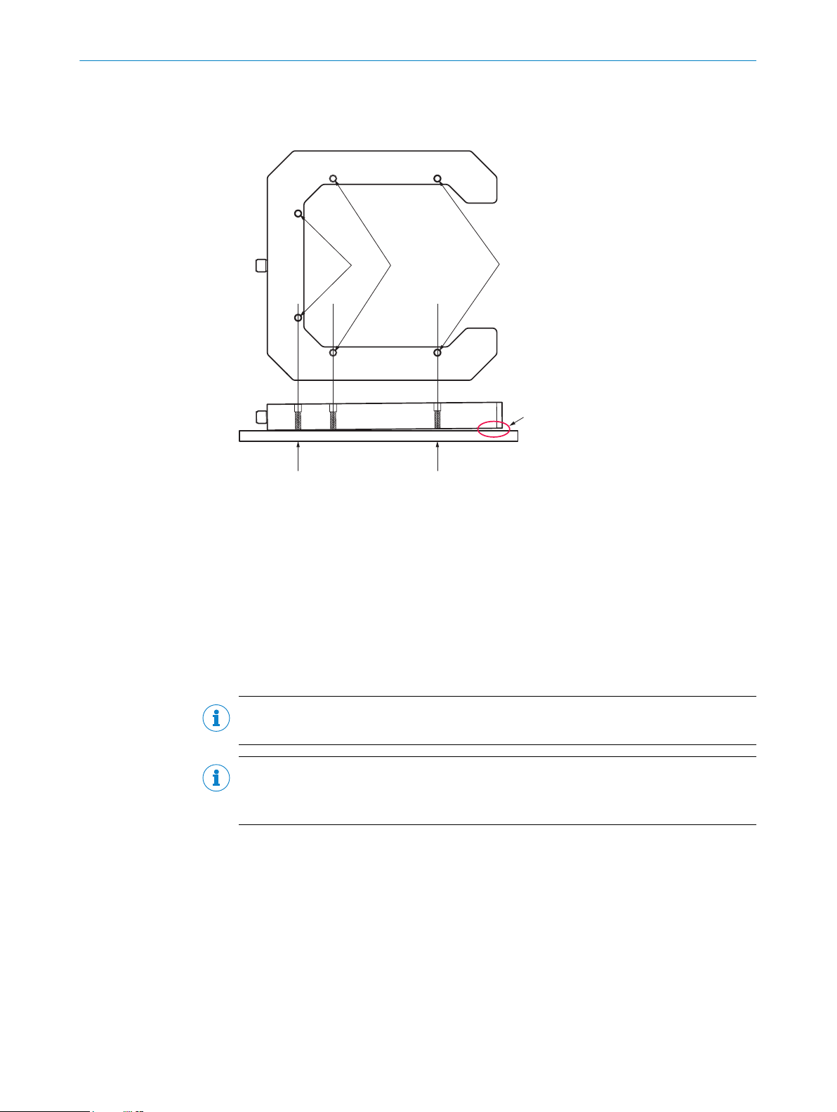
Figure 2: Mounting
Base screws
1
Optional base screws
2
Flank screws
3
No deformation!
4
Flank screws are loose
5
Base screws are tight
6
Normal mounting is recommended to be done with the base screws.
To obtain better stability the optional base screws can be used.
NOTE
It is important that the mounting surface is flat.
NOTE
To obtain full vibration resistance all 6 screws are to be used.
This requires an absolute flat mounting surface to avoid twisting of the sensor.
The reference points of the respective fixing holes to the crossed light beam can be
seen in the dimensional drawing, see figure 8.
5 Electrical installation
8023382.14JZ | SICK
Subject to change without notice
The sensors must be connected in a voltage-free state (UV = 0 V). The following informa‐
tion must be observed, depending on the connection type:
– Plug connection
Only apply voltage/switch on the voltage supply (UV > 0 V) once all electrical connec‐
tions have been established.
7
Page 8
1
2
5
4 3
3
1
2
5 ELECTRICAL INSTALLATION
Explanations of the connection diagram (Tables 2–7):
Q = switching outputs
5.1 DC
DC: 10 V ... 30 V DC, see "Technical data", page 11
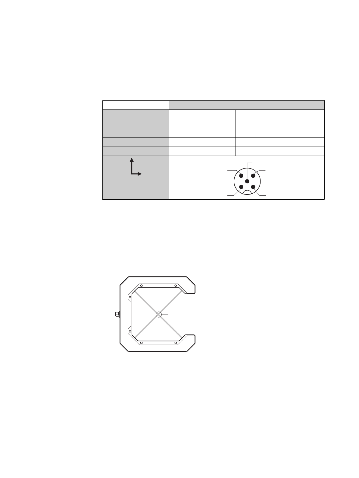
Table 1: DC
WFZ
1 BN + (L+)
2 WH Q2
3 BU - (M)
4 BK Q1
5 GY ET
6 Commissioning
1 Alignment: Positioning of objects in the crossed light beams
If one of the two crossed light beams is interrupted, this is signaled by the respective
switching behavior of Q1/Q2.
If light beam 1 is interrupted, switching output Q1 (pin 4) is deactivated.
If light beam 2 is interrupted, switching output Q2 (pin 2) is deactivated.
If an object covers both light beams, light beams 1+2 are interrupted and signaled by
switching outputs Q1 + Q2.
Figure 3: Switching outputs
1
2
3
Light beam 1, Q1
Light beam 2, Q2
Crossing point
8
8023382.14JZ | SICK
Subject to change without notice
Page 9

1.
2.
3.
1
2
3
COMMISSIONING
Figure 4: Reference points
The size of the object must be taken into account when positioning the switching point, see
figure 4.
The positioning procedure is carried out as follows:
Point determination
1. Move the tool into the WFZ until a switching output switches
2. Move the tool sideways until the second switching output switches
3. Move back to the central position and then move towards the center of the fork until
the crossing point is reached and both switching outputs switch
6
8023382.14JZ | SICK
Subject to change without notice
Figure 5: Point determination at the object tip
The alignment of the tool on the Z axis can also be ascertained by repositioning the tool on
the Z axis after point determination has been carried out (Step 4, 5 and 6).
9
Page 10

4
5
6
7 TROUBLESHOOTING
Figure 6: Second point determination
If two points on the tool’s Z axis lie within the WFZ’s crossing point, the tool is not only cen‐
trally aligned but also perpendicular to the WFZ.
Figure 7: Correct positioning in the crossing point, perpendicular to the WFZ
2 Teach-in function
Route pin 5 and gray cable to + (L+) for > 1 s. The yellow LEDs flash during the teach-in
procedure.
NOTE
For maximum accuracy, we recommend using the teach-in function before every measure‐
ment. At least, however:
•
•
•
3 PNP (Load → M): light path free, output (Q) high
7 Troubleshooting
The Troubleshooting table indicates measures to be taken if the sensor stops working.
10
after initial commissioning of the sensor
after cleaning
if the light beams display a weak signal, even though the light path is clear
8023382.14JZ | SICK
Subject to change without notice
Page 11

Table 2: Troubleshooting
LED indicator/fault pattern Cause Measures
Green LED does not light up or
flickers
Q-LED flashes yellow Sensor is still ready for opera‐
One of the two Q-LEDs do not
light up
8 Disassembly and disposal
The sensor must be disposed of according to the applicable country-specific regula‐
tions. Efforts should be made during the disposal process to recycle the constituent
materials (particularly precious metals).
No voltage or voltage below
the limit values
Voltage interruptions Ensure there is a stable power
Sensor is faulty If the power supply is OK,
tion, but the operating condi‐
tions are not ideal
The respective light beam is
interrupted
The optical surfaces are cont‐
aminated
Check the power supply,
check all electrical connec‐
tions (cables and plug connec‐
tions)
supply without interruptions
replace the sensor
Cleaning of the optical sur‐
faces. Perform teach-in again.
Remove object from light
beam
Cleaning of the optical sur‐
faces. Perform teach-in again.
NOTE
Disposal of batteries, electric and electronic devices
•
•
•
9 Maintenance
SICK sensors are maintenance-free.
We recommend doing the following regularly:
•
•
No modifications may be made to devices.
Subject to change without notice. Specified product properties and technical data are
not written guarantees.
According to international directives, batteries, accumulators and electrical or
electronic devices must not be disposed of in general waste.
The owner is obliged by law to return this devices at the end of their life to the
respective public collection points.
This symbol on the product, its package or in this document, indicates
that a product is subject to these regulations.
Clean the external lens surfaces
Check the screw connections and plug-in connections
10 Technical data
WFZ
Laser class I
8023382.14JZ | SICK
Subject to change without notice
11
Page 12

220 (8.66)
120 (4.72)
5.4 (0.21)
29.5
(1.16)
63 (2.48)
100 (3.94)
220 (8.66)
167 (6.57)
156 (6.14)
100 (3.94)
113 (4.45)
78 (3.07)
3
3
1
25 (0.98)
2
4
3
10 TECHNICAL DATA
WFZ
Wavelength 650 nm
Fork width 120 mm
Fork depth 185 mm
Smallest detectable object (MDO) 0.5 mm
Switching function Light switching
Supply voltage V
S
Current consumption < 100mA
Output current I
max.
Max. switching frequency 1,000 Hz
10 V DC ... 30 V DC
2)
100 mA
3)
Reproducibility ± 0.01 mm
Max. response time 0.5 ms
4)
Initialization time 50 ms
Enclosure rating IP67
Protection class III
Ambient operating temperature -10 °C ... +50 °C
Storage temperature -30 °C ... +65 °C
1)
Limit value; operation in short-circuit protection mains max. 8 A; residual ripple max. 5 V
2)
Without load.
3)
With light / dark ratio 1:1
4)
Signal transit time with resistive load
5)
Do not bend cables below 0 °C.
ss
1)
5)
Dimensional drawing
Figure 8: Dimensional drawing
Detection axes
1
Male connector, M12, 5-pin
2
12
8023382.14JZ | SICK
Subject to change without notice
Page 13

Fixing hole Ø 5.4 mm
3
LED indicator
4
TECHNICAL DATA 10
8023382.14JZ | SICK
Subject to change without notice
13
Page 14

WFZ
Gabelsensoren
B E T R I E B S A N L E I T U N G
de
en
Page 15

Beschriebenes Produkt
2006/42/EC
NO
SAFETY
WFZ
Hersteller
SICK AG
Erwin-Sick-Str. 1
79183 Waldkirch
Deutschland
Rechtliche Hinweise
Dieses Werk ist urheberrechtlich geschützt. Die dadurch begründeten Rechte bleiben
bei der Firma SICK AG. Die Vervielfältigung des Werks oder von Teilen dieses Werks ist
nur in den Grenzen der gesetzlichen Bestimmungen des Urheberrechtsgesetzes zuläs‐
sig. Jede Änderung, Kürzung oder Übersetzung des Werks ohne ausdrückliche schriftli‐
che Zustimmung der Firma SICK AG ist untersagt.
Die in diesem Dokument genannten Marken sind Eigentum ihrer jeweiligen Inhaber.
© SICK AG. Alle Rechte vorbehalten.
Originaldokument
Dieses Dokument ist ein Originaldokument der SICK AG.
8023382.14JZ | SICK
Subject to change without notice
15
Page 16

INHALT
Inhalt
11 Allgemeine Sicherheitshinweise..................................................... 17
12 Bestimmungsgemäße Verwendung............................................... 17
13 Bedien- und Anzeigeelemente........................................................ 18
14 Montage.............................................................................................. 19
15 Elektrische Installation..................................................................... 19
15.1 DC.............................................................................................................. 20
16 Inbetriebnahme................................................................................. 20
17 Störungsbehebung............................................................................ 22
18 Demontage und Entsorgung............................................................ 23
19 Wartung.............................................................................................. 23
20 Technische Daten.............................................................................. 24
16
8023382.14JZ | SICK
Subject to change without notice
Page 17

11 Allgemeine Sicherheitshinweise
2006/42/EC
NO
SAFETY
EN/IEC 60825-1:2014
IEC60825-1:2007
LASERKL ASSE 1
Laser
1
Maximale Pulsleistung: < 2,5 mW
Impulsdauer: 4 µs
Wellenlänge: 650 - 670 nm
Entspricht 21 CFR 1040.10
und 1040.11 mit Ausnahme von
Abweichungen nach
Laser-Hinweis 50, 24. Juni 2007
■
Vor der Inbetriebnahme die Betriebsanleitung lesen.
■
Anschluss, Montage und Einstellung nur durch Fachpersonal.
■
Kein Sicherheitsbauteil gemäß EU-Maschinenrichtlinie.
■
Gerät bei Inbetriebnahme vor Feuchte und Verunreinigung schützen.
■
Diese Betriebsanleitung enthält Informationen, die während des Lebenszyklus des
Sensors notwendig sind.
■
Die Strahlung des Sendelichtes darf nicht durch zusätzliche optische Bauteile
fokussiert werden.
ALLGEMEINE SICHERHEITSHINWEISE 11
12 Bestimmungsgemäße Verwendung
8023382.14JZ | SICK
Subject to change without notice
ACHTUNG
ACHTUNG: Eingriffe oder Manipulationen oder nicht bestimmungsgemäße Verwendung
kann zu gefährlicher Belastung durch Laser-Lichtstrahlung führen.
Das Einweg-Lichtschranken-System WFZ besteht aus zwei optoelektronischen Sendeund Empfangseinheiten. Die jeweiligen Sende- und Empfangseinheiten sind gekreuzt
angeordnet, sodass Objekte im Mittelpunkt des Kreuzungspunkts, durch Signalisierung
beider Schaltausgänge (Q1 + Q2) positioniert werden können. Das WFZ wird zum opti‐
schen, berührungslosen Erfassen und Positionieren von Objekten eingesetzt.
17
Page 18

4
4
2
3
6
5
7
4
1
13 BEDIEN- UND ANZEIGEELEMENTE
13 Bedien- und Anzeigeelemente
Abbildung 9: Anzeige LEDs
Deckelseite = obere Seite
1
Detektionsachse
2
Stecker M12, 5-polig
3
Befestigungsbohrung Ø 5,4 mm
4
Anzeige-LED grün: Betriebsspannung aktiv
5
Anzeige-LED gelb: Status Lichtempfang Q2
6
Anzeige-LED gelb: Status Lichtempfang Q1
7
18
8023382.14JZ | SICK
Subject to change without notice
Page 19

14 Montage
1 2 3
6 5
4
MONTAGE 14
Abbildung 10: Montage
1
2
3
4
5
6
Zur normalen Montage der WFZ wird empfohlen, die Basisschrauben zu verwenden.
Um eine bessere Stabilität zu erzielen, können die optionalen Basisschrauben verwen‐
det werden.
HINWEIS
Es ist wichtig, dass die Montageoberfläche eben ist.
HINWEIS
Um die maximale Vibrationsfestigkeit zu erreichen, müssen alle sechs Befestigungs‐
bohrungen verwendet werden.
Dies erfordert eine absolut ebene Montagefläche, um ein Verdrehen des Sensors zu
vermeiden.
Die Bezugspunkte der jeweiligen Befestigungsbohrungen zum gekreuzten Lichtstrahl
kann der Maßzeichnung entnommen werden, siehe Abbildung 16.
Basisschrauben
Optionale Basisschrauben
Gabelschrauben
Keine Verformung!
Gabelschrauben sind lose
Basisschrauben sind fest
15
8023382.14JZ | SICK
Subject to change without notice
Elektrische Installation
Anschluss der Sensoren muss spannungsfrei (UV = 0 V) erfolgen. Je nach Anschlussart
sind die folgenden Informationen zu beachten:
– Steckeranschluss
19
Page 20

1
2
5
4 3
3
1
2
15 ELEKTRISCHE INSTALLATION
Erst nach Anschluss aller elektrischen Verbindungen die Spannungsversorgung (UV > 0
V) anlegen bzw. einschalten.
Erläuterungen zum Anschlussschema (Tabellen 2-7):
Q = Schaltausgänge
15.1 DC
DC: 10 V ... 30 V DC, siehe "Technische Daten", Seite 24
Tabelle 3: DC
WFZ
1 BN + (L+)
2 WH Q2
3 BU - (M)
4 BK Q1
5 GY ET
16 Inbetriebnahme
1 Ausrichtung: Positionierung von Objekten in den gekreuzten Lichtstrahlen
Das Unterbrechen eines der beiden gekreuzten Lichtstrahlen wird durch das jeweilige
Schaltverhalten Q1 / Q2 signalisiert.
Wird der Lichtstrahl 1 unterbrochen, so wird der Schaltausgang Q1 (pin 4) deaktiviert.
Wird der Lichtstrahl 2 unterbrochen, so wird der Schaltausgang Q2 (pin 2) deaktiviert.
Deckt ein Objekt beide Lichtstrahlen ab, so werden die Lichtstrahlen 1 + 2 unterbrochen
und durch die Schaltausgänge Q1 + Q2 signalisiert.
Abbildung 11: Schaltausgänge
1
2
3
Lichtstrahl 1, Q1
Lichtstrahl 2, Q2
Kreuzungspunkt
20
8023382.14JZ | SICK
Subject to change without notice
Page 21

1.
2.
3.
1
2
3
INBETRIEBNAHME
Abbildung 12: Bezugspunkte
Bei der Schaltpunktpositionierung muss die Größe des Objektes berücksichtigt werden,
siehe Abbildung 12.
Der Positioniervorgang kann wie folgt vorgenommen werden:
Punktbestimmung
1. Mit dem Werkstück in das WFZ einfahren, bis ein Schaltausgang schaltet
2. Das Werkstück seitlich bewegen, bis der zweite Schaltausgang schaltet
3. Zurück zur mittleren Position bewegen und anschließend Richtung Gabelmitte bewe‐
gen bis der Kreuzungspunkt erreicht ist und beide Schaltausgänge schalten
16
8023382.14JZ | SICK
Subject to change without notice
Abbildung 13: Punktbestimmung an der Objektspitze
Die Ausrichtung des Werkstücks auf der Z-Achse kann zusätzlich ermittelt werden, indem
das Werkstück nach der Punktbestimmung auf der Z-Achse verschoben nochmals positio‐
niert wird (Schritt 4, 5 und 6).
21
Page 22

4
5
6
17 STÖRUNGSBEHEBUNG
Abbildung 14: Erneute Punktbestimmung
Wenn zwei Punkte auf der Z-Achse des Werkstücks im Kreuzungspunkt des WFZ liegen, ist
das Werkstück nicht nur mittig sondern auch senkrecht zum WFZ ausgerichtet.
Abbildung 15: Korrekte Positionierung im Kreuzungspunkt, senkrecht zum WFZ
2 Teach-in-Funktion
Pin 5 bzw. graue Leitung > 1 s auf + (L+) legen. Während des Teach-Vorgangs blinken die
gelben LED-Anzeigen.
HINWEIS
Es wird empfohlen, für die maximale Messgenauigkeit die Teach-in-Funktion vor jeder Mes‐
sung durchzuführen. Mindestens aber:
nach der Erstinbetriebnahme des Sensors
•
nach der Reinigung
•
wenn die Lichtstrahlen ein schwaches Signal anzeigen, obwohl der Lichtweg frei ist
•
3 PNP (Last → M): Lichtweg frei, Ausgang (Q) High
17 Störungsbehebung
Tabelle Störungsbehebung zeigt, welche Maßnahmen durchzuführen sind, wenn die
Funktion des Sensors nicht mehr gegeben ist.
22
8023382.14JZ | SICK
Subject to change without notice
Page 23

Tabelle 4: Störungsbehebung
Anzeige-LED / Fehlerbild Ursache Maßnahme
Grüne LED leuchtet nicht bzw.
flackert
Q-LED blinkt gelb Sensor ist noch betriebsbe‐
Eine der beiden Q-LEDs leuch‐
tet nicht
18 Demontage und Entsorgung
keine Spannung oder Span‐
nung unterhalb der Grenz‐
werte
Spannungsunterbrechungen Sicherstellen einer stabilen
Sensor ist defekt Wenn Spannungsversorgung
reit, aber die Betriebsbedin‐
gungen sind nicht optimal
Der entsprechende Lichtstrahl
ist unterbrochen
Die optischen Flächen sind
verschmutzt
Spannungsversorgung prüfen,
den gesamten elektrischen
Anschluss prüfen (Leitungen
und Steckerverbindungen)
Spannungsversorgung ohne
Unterbrechungen
in Ordnung ist, dann Sensor
austauschen
Reinigung der optischen Flä‐
chen. Teach-in erneut durch‐
führen.
Objekt aus Lichtstrahl entfer‐
nen
Reinigung der optischen Flä‐
chen. Teach-in erneut durch‐
führen.
19 Wartung
Die Lichtschranke muss entsprechend den geltenden länderspezifischen Vorschriften
entsorgt werden. Bei der Entsorgung sollte eine werkstoffliche Verwertung (insbeson‐
dere der Edelmetalle) angestrebt werden.
HINWEIS
Entsorgung von Batterien, Elektro- und Elektronikgeräten
Gemäß den internationalen Vorschriften dürfen Batterien, Akkus sowie Elektro-
•
und Elektronikgeräte nicht mit dem Hausmüll entsorgt werden.
Der Besitzer ist gesetzlich verpflichtet, diese Geräte am Ende ihrer Lebensdauer
•
bei den entsprechenden öffentlichen Sammelstellen abzugeben.
•
Dieses Symbol auf dem Produkt, dessen Verpackung oder im vorliegen‐
den Dokument gibt an, dass ein Produkt den genannten Vorschriften unterliegt.
SICK-Sensoren sind wartungsfrei.
Wir empfehlen, in regelmäßigen Abständen
die optischen Grenzflächen zu reinigen
•
Verschraubungen und Steckverbindungen zu überprüfen
•
Veränderungen an Geräten dürfen nicht vorgenommen werden.
8023382.14JZ | SICK
Subject to change without notice
Irrtümer und Änderungen vorbehalten. Angegebene Produkteigenschaften und techni‐
sche Daten stellen keine Garantieerklärung dar.
23
Page 24

20 TECHNISCHE DATEN
20 Technische Daten
WFZ
Laserklasse I
Wellenlänge 650 nm
Gabelweite 120 mm
Gabeltiefe 185 mm
Kleinstes detektierbares Objekt (MDO) 0,5 mm
Schaltfunktion Hellschaltend
Versorgungsspannung U
Stromaufnahme < 100mA
Ausgangsstrom I
Schaltfolge max. 1.000 Hz
Reproduzierbarkeit ± 0,01 mm
Ansprechzeit max. 0,5 ms
Initialisierungszeit 50 ms
Schutzart IP67
Schutzklasse III
Betriebsumgebungstemperatur -10 °C ... +50 °C
Lagertemperatur -30 °C ... +65 °C
1)
Grenzwerte; Betrieb im kurzschlussgeschützten Netz max. 8 A; Restwelligkeit max. 5 V
2)
Ohne Last.
3)
Mit Hell- / Dunkelverhältnis 1:1
4)
Signallaufzeit bei ohmscher Last
5)
Unter 0 °C Leitung nicht verformen.
max.
V
10 V DC ... 30 V DC
2)
1)
100 mA
3)
4)
5)
ss
24
8023382.14JZ | SICK
Subject to change without notice
Page 25

Maßzeichnung
220
120
5,4
29,5
63
100
220
167
156
100
113
78
3
3
1
25
2
4
3
TECHNISCHE DATEN 20
Abbildung 16: Maßzeichnung
Detektionsachsen
1
Stecker, M12, 5-polig
2
Befestigungsbohrung Ø 5,4 mm
3
Anzeige LED
4
8023382.14JZ | SICK
Subject to change without notice
25
Page 26

Detailed addresses and further locations at www.sick.com
Australia
Phone +61 (3) 9457 0600
1800 33 48 02 – tollfree
E-Mail sales@sick.com.au
Austria
Phone +43 (0) 2236 62288-0
E-Mail office@sick.at
Belgium/Luxembourg
Phone +32 (0) 2 466 55 66
E-Mail info@sick.be
Brazil
Phone +55 11 3215-4900
E-Mail comercial@sick.com.br
Canada
Phone +1 905.771.1444
E-Mail cs.canada@sick.com
Czech Republic
Phone +420 234 719 500
E-Mail sick@sick.cz
Chile
Phone +56 (2) 2274 7430
E-Mail chile@sick.com
China
Phone +86 20 2882 3600
E-Mail info.china@sick.net.cn
Denmark
Phone +45 45 82 64 00
E-Mail sick@sick.dk
Finland
Phone +358-9-25 15 800
E-Mail sick@sick.fi
France
Phone +33 1 64 62 35 00
E-Mail info@sick.fr
Germany
Phone +49 (0) 2 11 53 010
E-Mail info@sick.de
Greece
Phone +30 210 6825100
E-Mail office@sick.com.gr
Hong Kong
Phone +852 2153 6300
E-Mail ghk@sick.com.hk
Hungary
Phone +36 1 371 2680
E-Mail ertekesites@sick.hu
India
Phone +91-22-6119 8900
E-Mail info@sick-india.com
Israel
Phone +972 97110 11
E-Mail info@sick-sensors.com
Italy
Phone +39 02 27 43 41
E-Mail info@sick.it
Japan
Phone +81 3 5309 2112
E-Mail support@sick.jp
Malaysia
Phone +603-8080 7425
E-Mail enquiry.my@sick.com
Mexico
Phone +52 (472) 748 9451
E-Mail mexico@sick.com
Netherlands
Phone +31 (0) 30 229 25 44
E-Mail info@sick.nl
New Zealand
Phone +64 9 415 0459
0800 222 278 – tollfree
E-Mail sales@sick.co.nz
Norway
Phone +47 67 81 50 00
E-Mail sick@sick.no
Poland
Phone +48 22 539 41 00
E-Mail info@sick.pl
Romania
Phone +40 356-17 11 20
E-Mail office@sick.ro
Russia
Phone +7 495 283 09 90
E-Mail info@sick.ru
Singapore
Phone +65 6744 3732
E-Mail sales.gsg@sick.com
Slovakia
Phone +421 482 901 201
E-Mail mail@sick-sk.sk
Slovenia
Phone +386 591 78849
E-Mail office@sick.si
South Africa
Phone +27 10 060 0550
E-Mail info@sickautomation.co.za
South Korea
Phone +82 2 786 6321/4
E-Mail infokorea@sick.com
Spain
Phone +34 93 480 31 00
E-Mail info@sick.es
Sweden
Phone +46 10 110 10 00
E-Mail info@sick.se
Switzerland
Phone +41 41 619 29 39
E-Mail contact@sick.ch
Taiwan
Phone +886-2-2375-6288
E-Mail sales@sick.com.tw
Thailand
Phone +66 2 645 0009
E-Mail marcom.th@sick.com
Turkey
Phone +90 (216) 528 50 00
E-Mail info@sick.com.tr
United Arab Emirates
Phone +971 (0) 4 88 65 878
E-Mail contact@sick.ae
United Kingdom
Phone +44 (0)17278 31121
E-Mail info@sick.co.uk
USA
Phone +1 800.325.7425
E-Mail info@sick.com
Vietnam
Phone +65 6744 3732
E-Mail sales
.gsg@sick.com
SICK
26
Subject to change without notice
8023382.14JZ | SICK
 Loading...