

Page 1
WSU 26/2 – WEU 26/2
Photoelectric Safety Switch
T
ECHNICAL D ESCRIPTION
Page 2

Technical Description
WSU 26/2 – WEU 26/2
Photoelectric Safety Switch
The information contained in
this document may be revised
or supplemented without prior
notice.
2
8 008 692/23-07-01 © SICK AG • Industrial Safety Systems • Germany • All rights reserved
Page 3

Technical Description
WSU 26/2 – WEU 26/2
Photoelectric Safety Switch
Contents
Contents
1 Document Information .................................................................................................. 5
1.1 About this document ..................................................................................................... 5
1.2 Target group .......................................................................................................................5
1.3 Scope of information ....................................................................................................6
1.4 Symbols used in this document ............................................................................6
2 Safety....................................................................................................................................... 7
2.1 General safety advice and protective measures........................................ 7
2.2 Application areas ............................................................................................................. 8
2.3 Intended use of the device ...................................................................................... 9
2.4 Environmental compatibilty ....................................................................................... 9
3 Product Description..................................................................................................... 10
3.1 Characteristics................................................................................................................ 10
3.2 Device functionality..................................................................................................... 10
4 Mounting ............................................................................................................................ 11
4.1 Positioning the sensors ........................................................................................... 11
4.2 Safety distance.............................................................................................................. 11
4.3 Distance to reflective surfaces........................................................................... 13
4.4 Multiple safeguarding ................................................................................................ 15
4.4.1 Mutual interference ................................................................................................. 16
4.5 Mechanical mounting.................................................................................................. 16
4.5.1 Corner mirrors ............................................................................................................. 18
5 Electrical Installation................................................................................................. 19
5.1 Test instructions............................................................................................................ 20
5.2 Spark suppression....................................................................................................... 20
5.3 Short-circuit monitoring............................................................................................. 21
5.4 Overvoltage protection (fuse)............................................................................... 21
5.5 Wiring diagram ................................................................................................................ 22
5.6 Alignment of WSU and WEU ................................................................................... 30
5.6.1 Alignment of WSU and WEU with Alignment Aid AR 60.................... 31
6 Test Instructions ............................................................................................................ 32
6.1 Pre-commissioning tests ......................................................................................... 32
6.2 Regular testing of the safety device by competent personnel...... 32
6.3 Daily testing of the safety module by competent personnel .......... 33
7 Maintenance .................................................................................................................... 34
8 Diagnostic Elements ................................................................................................... 35
9 Technical Data ............................................................................................................... 36
9.1 Overview technical data ........................................................................................... 36
9.2 Dimensional drawings ................................................................................................ 38
10 At a glance: Comparison of old versus new devices............................ 42
11 Selection Table ............................................................................................................ 43
11.1 Conversion list ............................................................................................................. 44
12 Accessories Selection Table ............................................................................... 45
13 Checklist .......................................................................................................................... 46
8 008 692/23-07-01 © SICK AG • Industrial Safety Systems • Germany • All rights reserved
3
Page 4

Technical Description
WSU 26/2 – WEU 26/2
Photoelectric Safety Switch
4
8 008 692/23-07-01 © SICK AG • Industrial Safety Systems • Germany • All rights reserved
Page 5

Technical Description
WSU 26/2 – WEU 26/2
Photoelectric Safety Switch
Document Information
Abbreviations
Chapter 1
PDM
WSU
WEU
OSSD
AOPD
Power-driven machinery (machinery, plant)
Photoelectric Safety Switch: Sender unit
Photoelectric Safety Switch: Receiver unit
Output Signal Switching Device
Active Optoelectronic Protective Device
1 Document Information
1.1 About this document
This document provides instructions for the operation of the WSU/WEU
photoelectric safety switch. It contains information on
Application
Mounting
Electrical installation
Commissioning
Maintenance
Ordering
1.2 Target group
The target group of this document is those who install, commission and
use the WSU/WEU photoelectric safety switch.
8 008 692/23-07-01 © SICK AG • Industrial Safety Systems • Germany • All rights reserved
5
Page 6

Chapter 1
Document Information
Technical Description
WSU 26/2 – WEU 26/2
Photoelectric Safety Switch
1.3 Scope of information
This technical description contains information on how to install,
commission and operate the device. Official and legal regulations must
always be observed. It is not possible to provide comprehensive
information on all these requirements in this document. In Germany, for
example, the Trade Association Directives (ZH 1/597 and ZH 1/281) in
particular must be observed.
Further information on health and safety with respect to optoelectronic
guarding systems can be obtained directly from your local SICK
distributor, e. g. Safe Machines (SICK guidelines on the operation of
optoelectronic guarding systems).
1.4 Symbols used in this document
Some information in this document is highlighted to ease rapid access to
this information:
Note
Explanation
Recommendation
WARNING
A note provides information on special features of the device.
An explanation gives basic information.
A recommendation assists in deciding upon the best action.
Warning!
A warning indicates actual or potential hazards. This is to reduce the risk
of accidents.
Always read warning notices carefully and follow them closely.
6
8 008 692/23-07-01 © SICK AG • Industrial Safety Systems • Germany • All rights reserved
Page 7

Technical Description
WSU 26/2 – WEU 26/2
Photoelectric Safety Switch
Safety
Chapter 2
2
Safety
WARNING
The devices can only perform their safety function if they are used
correctly and integrated into the process in a failsafe manner.
The WSU/WEU photoelectric safety switch meets the requirements of
Type 4 Safety Devices as stipulated in EN 61 496-1 and pr EN 50 100-2.
2.1 General safety advice and protective
measures
1 National and international regulations apply for the operation of non-
contact protection equipment as well as for commissioning and
regular maintenance checks, in particular
Machinery Safety Regulation 98/37 EC
Provision and Use of Work Equipment Regulations
89/665 EEC
Relevant safety regulations
Accident prevention regulations and safety guidelines
It is the responsibility of the manufacturers and operators of the
machine on which SICK protection equipment is used to discuss all
safety legislation, which may apply, with the responsible authorities
and to observe these rules and regulations.
2 Furthermore, our notes, in particular the Test Regulations (see
section ‘Tests’) in this Technical Description or the Operating
Instructions (such as use, assembly, installation or integration in the
machine control unit) must be observed.
3 The tests must be performed by qualified personell or by specially
authorised and instructed personnel and must be documented in
such a way as to be viewed and understood at any time.
4 These Operating Instructions shall be given to the employee
(operator) working with the machine on which SICK guarding systems
are installed. The employee shall be trained for their job and
operation of the equipment by a competent person.
5 The Test Protocol relating to use of the non-contact safety device is
printed at the end of these Technical Description. Acceptance testing
should be performed on the basis of that protocol.
6 Mounting and connection may only be done by qualified personnel.
Before commissioning, the mounting and connection must be
inspected by the operator’s responsible staff member, as is required
by the standards and directives of the specific country.
8 008 692/23-07-01 © SICK AG • Industrial Safety Systems • Germany • All rights reserved
7
Page 8
Chapter 2
Safety
Technical Description
WSU 26/2 – WEU 26/2
Photoelectric Safety Switch
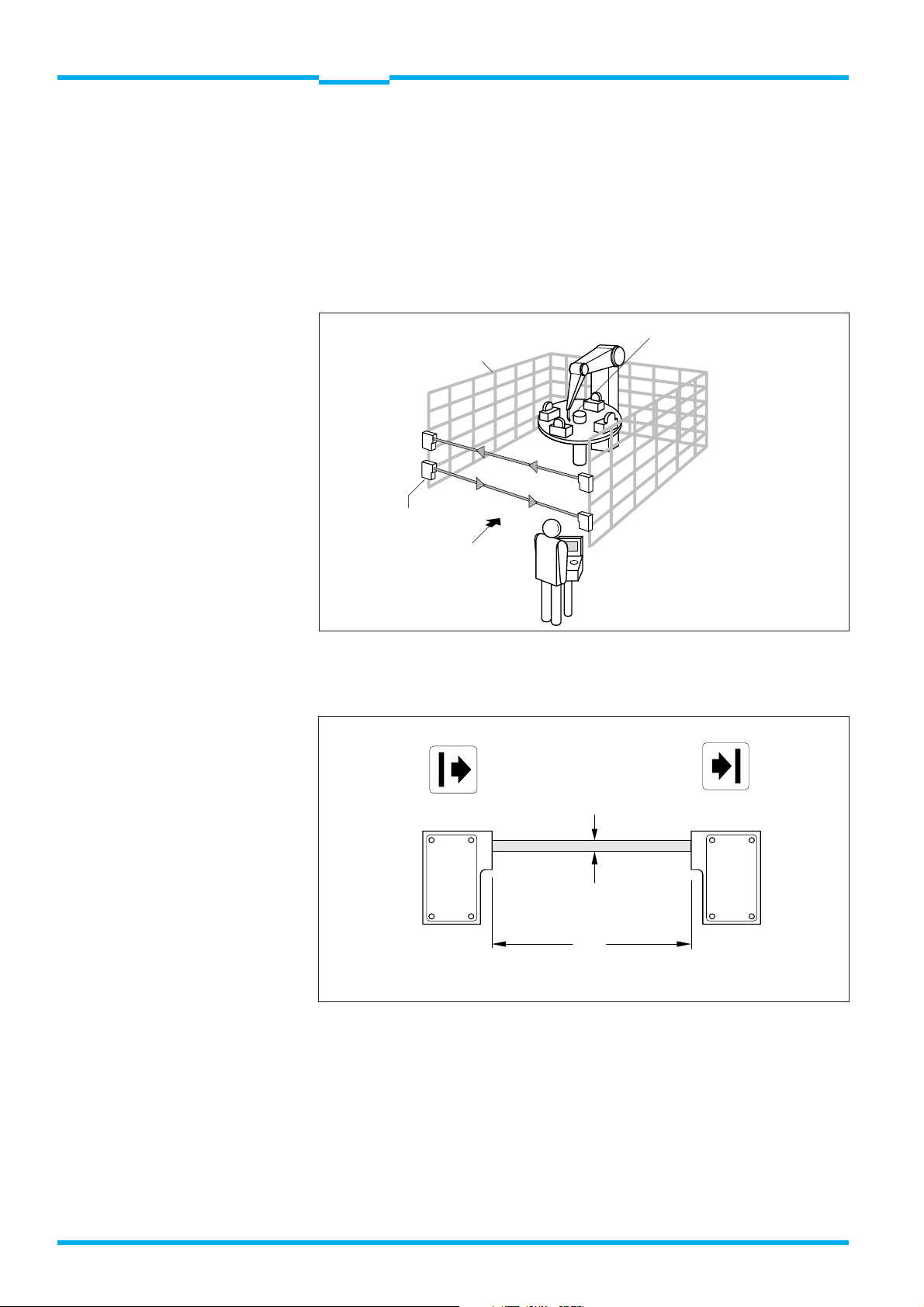
2.2 Application areas
The WSU/WEU 26/2 photoelectric safety switch is used as an access
safety system to hazardous areas around machinery or plant. The device
is securely mounted in the access area at a pre-determined safe
distance from the hazardous point. When the light beam is interrupted
the device transmits an emergency stop signal to the machinery or
plant.
Point-of-operation
Mechanical
mechanische
Absicherung
guarding
Gefahrstelle
Zugangssicherung
Entry/exit guarding
mit WSU/WEU
with WSU/WEU
Direction of entry
Eintrittsrichtung
into hazardous
in Gefahrbereich
area
Fig. 1: Entry/exit safeguarding using a WSU/WEU 26/2
The following key points are important for correct operation (Fig. 2):
Beam diameter
Lichtstrahldurchmesser
23 mm
WSU WEU
23 mm
RW
0.5 to 18 m
15 to 70 m
Fig. 2: System construction of the WSU/WEU 26/2
8
8 008 692/23-07-01 © SICK AG • Industrial Safety Systems • Germany • All rights reserved
Page 9

Technical Description
WSU 26/2 – WEU 26/2
Photoelectric Safety Switch
Safety
Chapter 2
2.3 Intended use of the device
The WSU/WEU photoelectric safety switch may only be used as
specified in Section 2.2 Application areas. The device may be operated
only in accordance with its technical specifications. Any other use or
modification – including during mounting and installation – will
invalidate any guarantee and any claim against SICK AG.
2.4 Environmental compatibility
The WSU/WEU photoelectric safety switch is designed to have the
lowest possible impact on the environment. It neither emits nor
contains any environmentally damaging substances, and consumes
minimal quantities of energy and resources.
Disposal
Unusable systems or systems beyond repair must be disposed of in
accordance with the regulations on refuse disposal currently valid in the
respective country.
The aluminium housing should be recycled. If possible, remove the
plastic front panel.
All electronic components can be simply dismantled. They should be
disposed of as special waste. SICK AG will not accept back unusable
systems or systems beyond repair.
When dismantling and disposing of components, provisions relating to
occupational safety, the environment and disposal should be observed.
8 008 692/23-07-01 © SICK AG • Industrial Safety Systems • Germany • All rights reserved
9
Page 10
Chapter 3
Product Description
Technical Description
WSU 26/2 – WEU 26/2
Photoelectric Safety Switch
3
Product Description
3.1 Characteristics
Special characteristics of the WSU/WEU 26/2 photoelectric safety
switch are:
easy installation
universal functionality
solid construction
various connecton options
universal power supply
wide scanning range
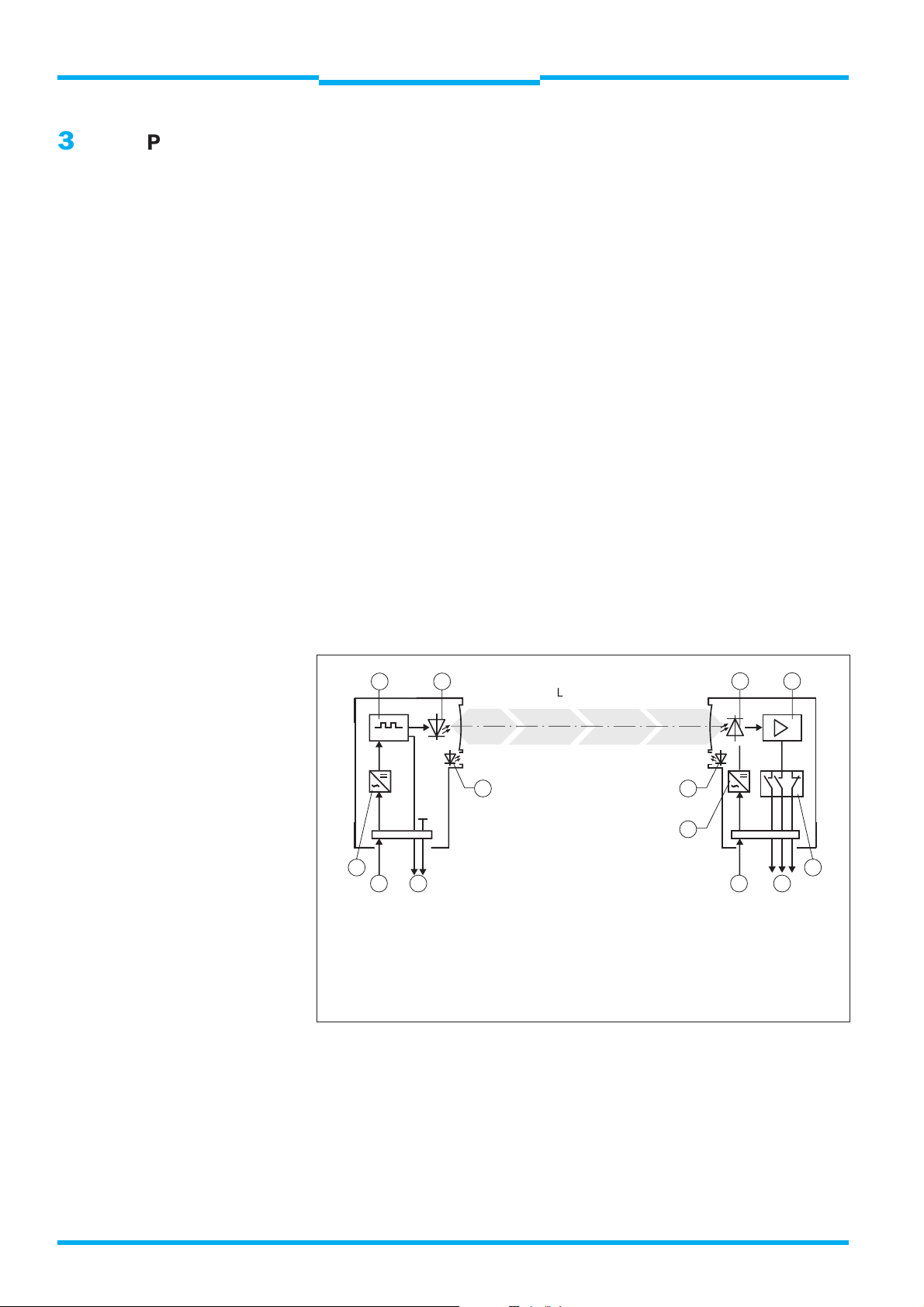
3.2 How the device functions
The housing of WSU/WEU consists of die-cast Aluminium. In the WSU,
an infrared sender diode emits pulse modulated light (Fig. 3).
If the light path is uninterrupted the output relays in the WEU are deenergized.
3 4
5 6
2
11 1 10
1
1 Connection for power supply
2 Power supply
3 Clock generator
4 Sender diode
5 LED, WSU
6 LED, WEU
Fig. 3: Principle of function of the WSU/WEU 26/2, AC version
Light beam
Lichtbündel
10 Outputs
11 Test contact
2
7 Photoelectric converter
8 Amplifier
9 Relay with positively-guided contacts
7 8
9
Diagnostic lights on the instruments signal the various operating
conditions (see 8 Diagnostic Elements). Their display, however, is not
safety related.
The diagnostic lights also serve as error diagnostics, see 8, Diagnostic
Elements.
10
8 008 692/23-07-01 © SICK AG • Industrial Safety Systems • Germany • All rights reserved
Page 11
Technical Description
WSU 26/2 – WEU 26/2
Photoelectric Safety Switch
Mounting
Chapter 4
4
Mounting
4.1 Positioning the sensors
The WSU/WEU can be operated in any position. Regulations regarding
safety distances must be observed as well as sufficient height of
beams above floor.
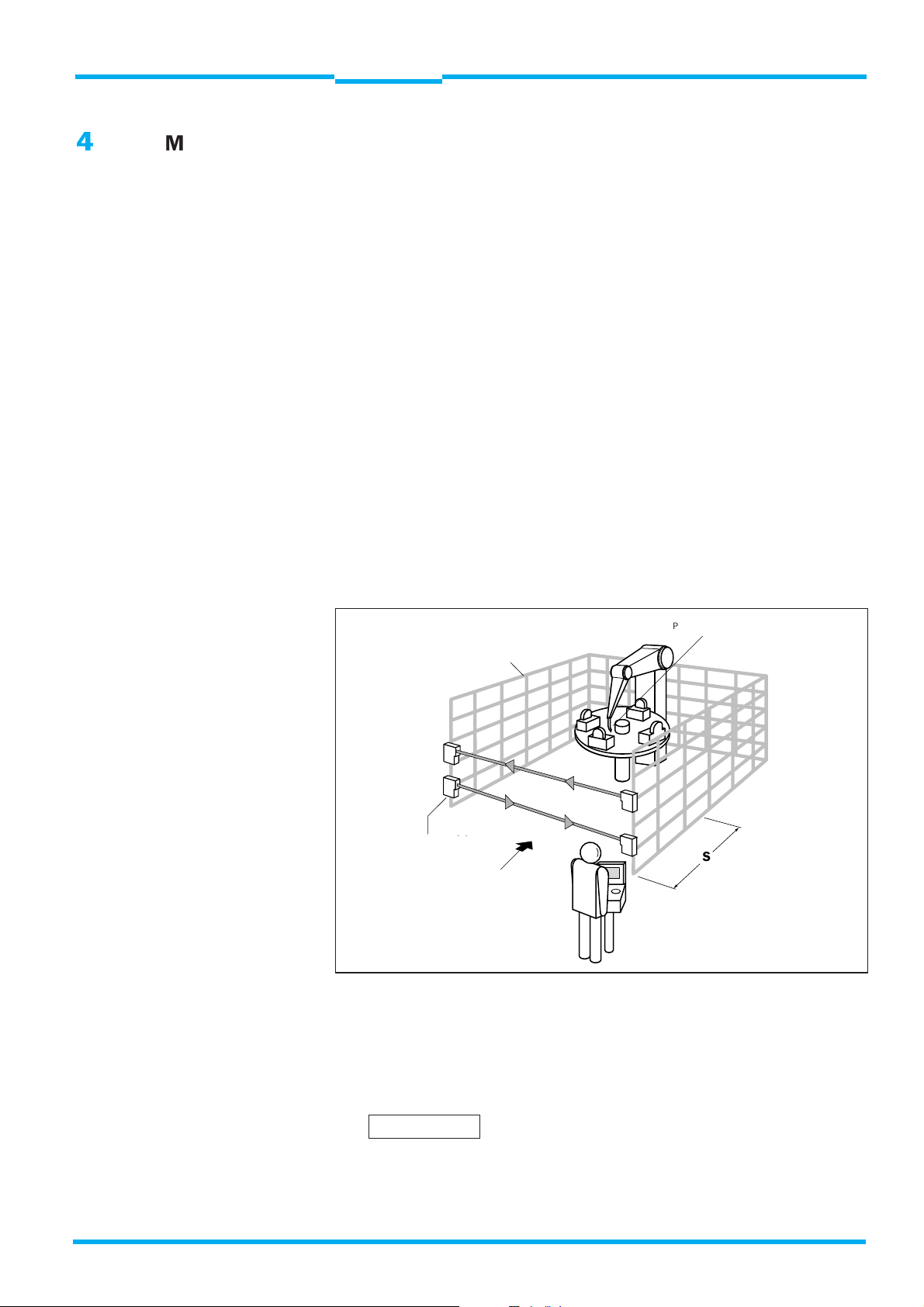
4.2 Safety distance
The WSU/WEU must be mounted such that, if the light beam is broken
during hazardous movement of the machinery, the point-of-operation can
only be reached when this hazardous movement has ceased. For this
purpose, a safety distance S must be maintained between the nearest
trapping point and the light beam (Fig. 4). The safety distance depends
on the machine stopping time and on the approach speed of the
personnel.
Point-of-operation
Mechanical
mechanische
guarding
Absicherung
Zugangssicherung
Entry/exit guarding
mit WSU/WEU
with WSU/WEU
Eintrittsrichtung
Direction of entry
in Gefahrbereich
into hazardous
area
Fig. 4: Safety distance S to light beam
Gefahrstelle
S
The machine stopping time must be determined by repeated measurements under practical conditions. 1.6 m/s is the recommended (by
EN 999) approach speed.
The safety distance is calculated as follows:
8 008 692/23-07-01 © SICK AG • Industrial Safety Systems • Germany • All rights reserved
11
Page 12
Chapter 4
Mounting
Technical Description
WSU 26/2 – WEU 26/2
Photoelectric Safety Switch
S = K · T + C
S Safety distance (mm)
K Approach speed 1.6 m/s
T Machine stopping time (ms) + response time of WEU
(see Technical Data)
C Dependent on number of beams (1, 2, or 3), see Table 1
Table 1 shows which C value must be used for which application.
Number of beams 1 2 3
Height of beam(s) 750 400 300
above floor (mm) 900 700
C 1200 850 850
Tab 1: Height of beams above floor
1100
WARNING
WARNING
Maintain safety distance!
The WSU/WEU must be mounted such that, if the light beam is broken
during hazardous movement of the machinery, the point-of-operation can
only be reached when the power-driven machinery is no longer in a
hazardous state.
For this purpose, a safety distance must be maintained between the
light beam and the nearest boundary of the point-of-operation. This
safety distance is determined according to pr EN 999.
EN 999
Safety of machinery
Approach speed of body parts for arrangement of protective systems
Danger of non-detection
People within the hazardous area but outside the light beam are not
detected. It must, however, be ensured that any hazardous state can
only be initiated when there is no one in the hazardous area.
The WSU/WEU may not be utilised as a hand- and finger protection
system.
12
Use and mounting of the protective systems is subject to the relevant
official rules and regulations. These provisions differ depending on the
area of application.
8 008 692/23-07-01 © SICK AG • Industrial Safety Systems • Germany • All rights reserved
Page 13
Technical Description
WSU 26/2 – WEU 26/2
Photoelectric Safety Switch
Mounting
Chapter 4
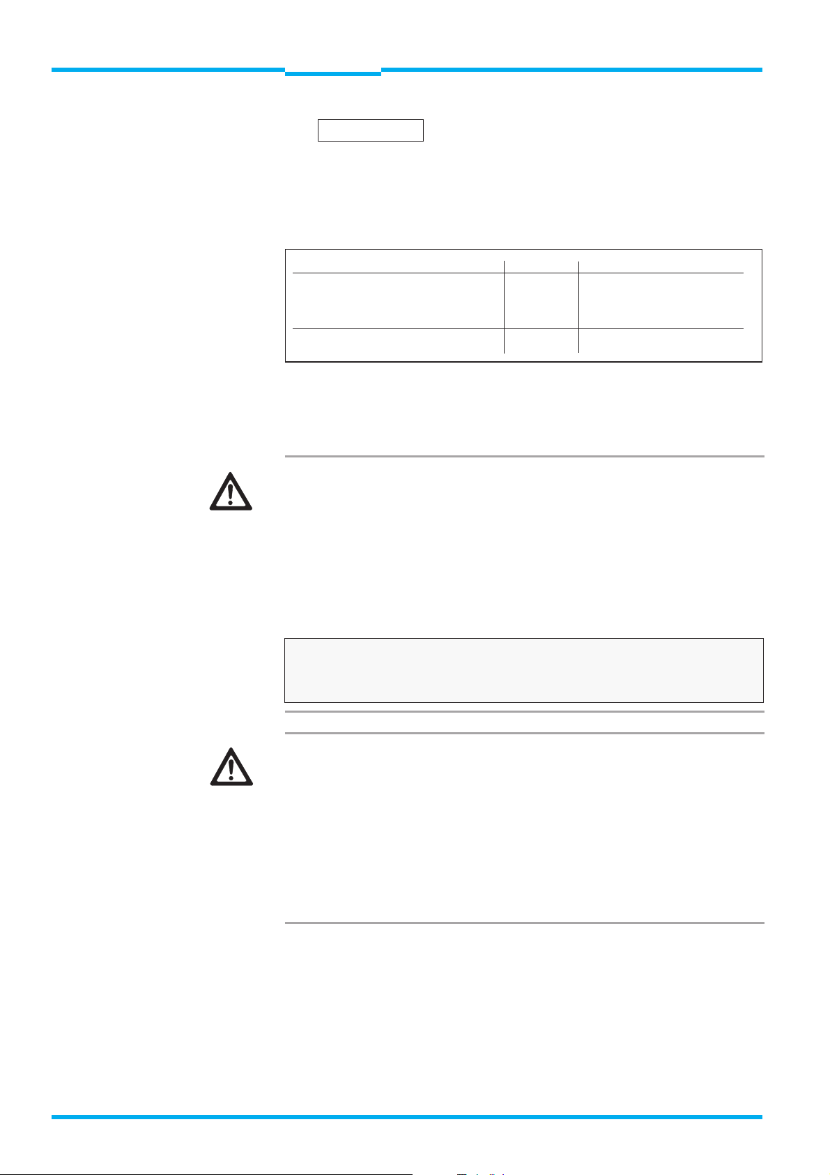
4.3 Distance to reflective surfaces
Reflective surfaces located (placed or fixed) within the sender and
receiver range, may cause reflection and thus prevent an obstacle from
being reliably detected (Fig. 5).
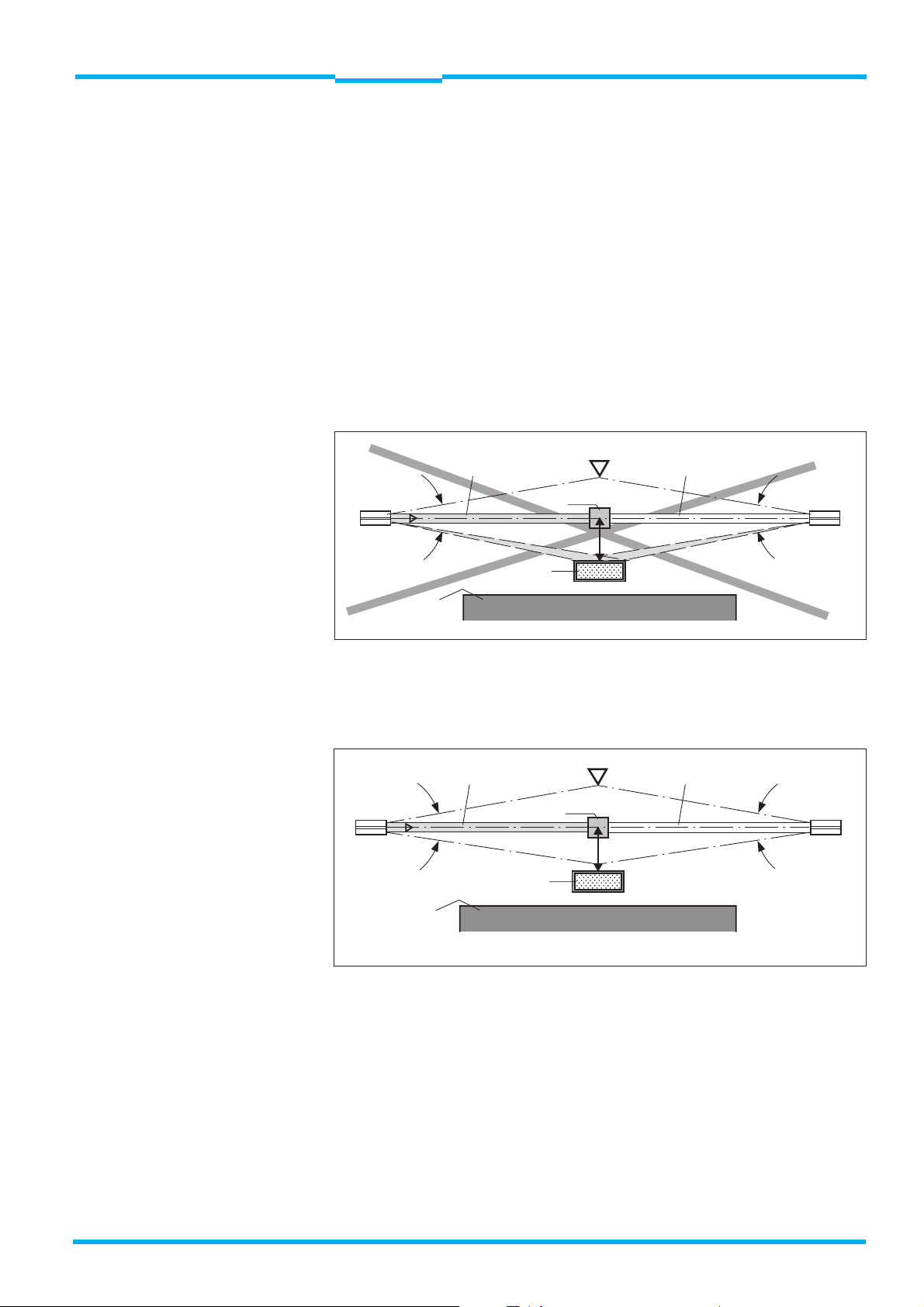
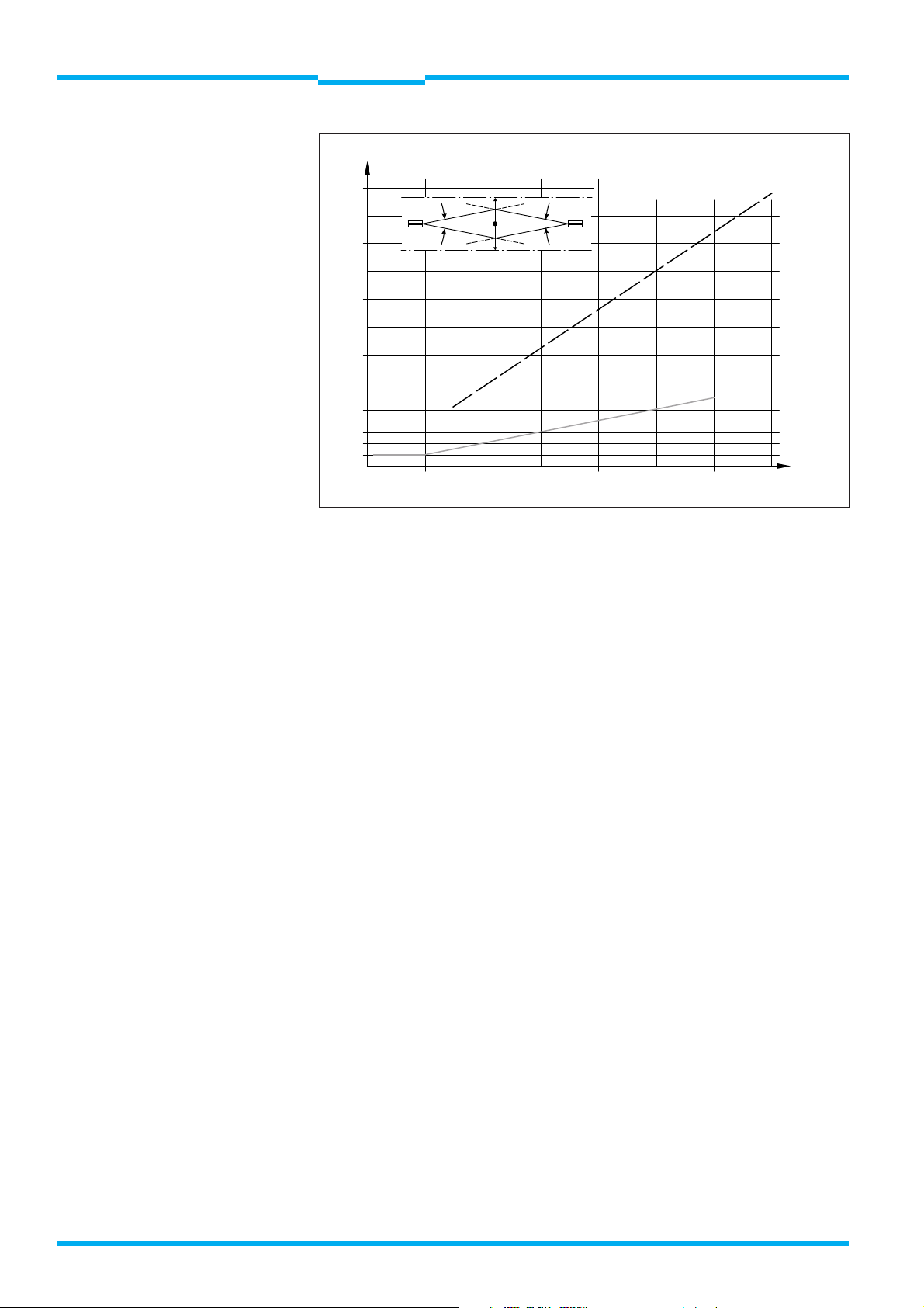
For this reason, a minimum distance “a” from reflective surfaces to
the optical axis (linear connection between transmitter and receiver)
must be maintained (Fig. 6). The distance “a” is dependent on the
distance between the sender and receiver (Fig. 7).
Testing for spurious reflection is described in Section 6 Test
Instructions.
Entry direction
Central beam
Obstacle
Beam array
broken
4
WSU WEU
4
Reflective object
(e. g. material container)
Boundary of
point-ofoperation
a
Deflection: “a” should be set higher
because of the reflection
Fig. 5: Incorrect mounting: reflective object in divergent light beam. No
detection of the obstacle due to reflection. No protection.
Entry direction
Central beam
WSU WEU
4˚
Reflective object
(e. g. material container)
Boundary of
point-ofoperation
Obstacle
a
Beam array
broken
4˚
Fig. 6: Correct mounting, correctly aligned: reflective object outside divergent
light beam. No reflection. The obstacle is clearly detected.
8 008 692/23-07-01 © SICK AG • Industrial Safety Systems • Germany • All rights reserved
13
Page 14
Chapter 4
Mounting
a (mm)
Technical Description
WSU 26/2 – WEU 26/2
Photoelectric Safety Switch
2500
2000
1500
1000
500
400
300
200
100
WSU WEU
4˚
3
10
20
a
30
4˚
9
12
40
15
50
a
6
Fig. 7: Distance “a” as a function of scanning range RW
a (18 m)
18
60
a (70 m)
21
70
RW (m)
RW I
RW II
14
8 008 692/23-07-01 © SICK AG • Industrial Safety Systems • Germany • All rights reserved
Page 15
Technical Description
WSU 26/2 – WEU 26/2
Photoelectric Safety Switch
Mounting
Chapter 4
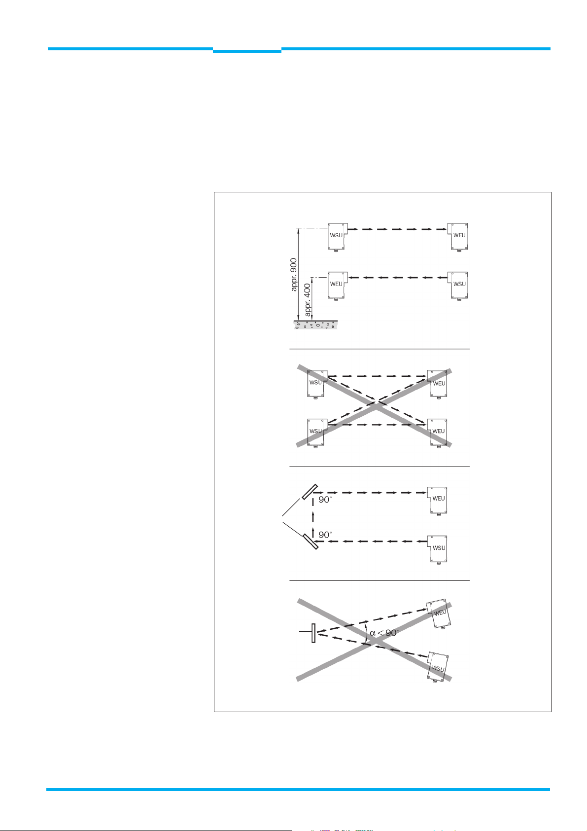
4.4 Multiple safeguarding
When using two WSU/WEU units in a protective system, the possibility
of mutual interference must be excluded. Since the light beam of the
WSU diverges, the cross-section of the beam increases as the distance
between the WSU and WEU increases. The following conditions must
therefore be met when arranging the WSU/WEU (Fig. 8).
Correct
Wrong
Correct
Corner mirror
Wrong
Corner mirror
Fig. 8: Safeguarding a hazardous area with WSU/WEU
8 008 692/23-07-01 © SICK AG • Industrial Safety Systems • Germany • All rights reserved
15
Page 16

Chapter 4
Mounting
Technical Description
WSU 26/2 – WEU 26/2
Photoelectric Safety Switch
4.4.1 Mutual interference
The transmitted light beam of the WSU must only be received by the
corrsponding WEU. To prevent mutual interference between several
WSU/WEU installations arranged adjacent to or above each other, the
specified beam diameters must be taken into account when mounting
the devices (Fig. 9), see 9 Technical Data.
WARNING
WEU
WSU
WSU
WSU WSU
WEU
WEU
WSU
WSU
WEU
WEU
WEU
Fig. 9: Mounting of two WSU/WEU units in series
There are two versions of WSU ...
... for operating ranges 0.5 - 18 m and 15 - 70 m. The WSU for 15 - 70
m must not be used for operating ranges below 15 m. The operating
range is given on the information plate attached to the device.
4.5 Mechanical mounting
Note
WSU and WEU units can be mounted on one of the sides of their housing or using the mounting bracket, depending on site circumstances.
The mounting bracket greatly assists alignment. The devices can be
mounted in any operating orientation. However, the WSU and WEU
should be mounted such that the axis of the light beam emitted by the
WSU always matches the axis of the WEU optic (alignment sight).
The mounting brackets should be affixed so that all fixing screws are
easily accessible for alignment purposes. Fig. 10 shows examples. The
devices should be mounted such that the opposing device can be
aligned using the alignment sight.
16
8 008 692/23-07-01 © SICK AG • Industrial Safety Systems • Germany • All rights reserved
Page 17

Technical Description
WSU 26/2 – WEU 26/2
Photoelectric Safety Switch
Mounting
Chapter 4
Do not use with
WSU/WEU 26/2-xx4
Do not use with
WSU/WEU 26/2-xx4
Note
plug version
Note
plug version
Mounting bracket
Part No. 2 007 900
Fig. 10: Mounting options using a mounting bracket
8 008 692/23-07-01 © SICK AG • Industrial Safety Systems • Germany • All rights reserved
17
Page 18

Chapter 4
Mounting
Technical Description
WSU 26/2 – WEU 26/2
Photoelectric Safety Switch
4.5.1 Corner mirrors
In conjunction with corner mirrors the WSU/WEU provides multisided,
two-beam access protection (Fig. 11).
Note
Note
The use of corner mirrors reduces the scanning range of the WSU/WEU
system as indicated in the table.
The use of more than 2 mirrors (Fig. 12) requires a very accurate alignment. Use of alignment aid AR 60 is recommended.
Number of mirrors 0.5 ... 18 m WSU 15 ... 70 m WSU
1 17 m 68 m
2 15.5 m 61 m
3 13 m 51 m
4 11 m 42 m
Tab. 2: Reduction in scanning range when using corner mirrors with a = 90°
Corner mirror
Hazardous area
Corner mirror
Hazardous area
Reflection
possible
Power-driven
machinery (PDM)
Corner mirror
Power-driven
machinery
(PDM)
Safety
distance too
small
Umlenkspiegel
Corner mirror
Umlenkspiegel
Corner mirror
18
Fig. 11: Multi-sided protection of
hazardous areas
Fig. 12: Two-beam protection with a
WSU/WEU-26-system
8 008 692/23-07-01 © SICK AG • Industrial Safety Systems • Germany • All rights reserved
Page 19

Technical Description
WSU 26/2 – WEU 26/2
Photoelectric Safety Switch
Electrical Installation
Chapter 5
5
Electrical Installation
Note
Depending on type, the WSU/WEU 26/2 photoelectric safety switch is
available for the following supply voltages:
24 V DC,
115 V AC or
230 V AC
The information plate gives details.
The two system components must be of the same voltage version and
the same scanning range.
Before connection, check that the supply voltage and mains frequency
on-site are consistent with the specifications on the information plate.
The cable is fed through the PG connector and connected inside the
device, or connected to the equipment plug. The wiring diagram is
depicted again on the housing cover of the respective device.
WARNING
WARNING
The enclosure rating of the devices can only be guaranteed when the
cable is properly clamped in the PG connector and the housing seals fit
correctly. Where long leads are used, the cable cross-sections should
be chosen to ensure the devices are always supplied with the required
voltage (see 9 Technical Data).
Single- or fine-wire conductors up to 1.5 mm2 can be connected to the
clamp terminals (to VDE 0607). Strip to length: 11 mm.
Switch off power!
The electrical connection of the WSU/WEU must only be made or
changed with the power disconnected.
Unscrew the housing cover to connect the WSU/WEU with a PG
connector.
Use both normally-open contacts!
At least two outputs must be connected to the control unit of the
machine being protected (Figs. 22/23). An electromagnetic contact
element (relay) must be connected to each of the two outputs
(normally-open contacts).
8 008 692/23-07-01 © SICK AG • Industrial Safety Systems • Germany • All rights reserved
19
Page 20

Chapter 5
WARNING
Electrical Installation
Technical Description
WSU 26/2 – WEU 26/2
Photoelectric Safety Switch
Use normally-open outputs!
In new installations, both normally-open outputs must be independently
supplied to two contact elements (e.g. contactors, relays). The normallyclosed output should be used only for functions that are not directly
safety-related.
Explanation
In general, the normally-open contacts
should be used. However, in older
installations a normally-open / normally-
456789
closed combination may have been selected.
This no longer conforms to presentday safety requirements. Should the
WSU/WEU be installed on existing installations,
K2
both normally-open contacts should
K1
be connected in series to the normallyclosed contact as a second channel.
Fig. 13: Installation in
old factories
5.1 Test instructions
The test function enables a check to be made on the connected
contactor mechanisms. In the process, the sender is switched off when
the normally-closed contact is opened. The testing functions is
triggered during a minimum opening time (see 9 Technical Data).
The testing function should be performed via the machinery control
system in the non-hazardous phase (e. g. during a non-hazardous
motion). If the test fails, the power-driven machinery — initiated via the
WEU – must receive a stop signal from the machinery control system.
20
Use the testing function as described!
The test input must be used exclusively as described.
WARNING
5.2 Spark suppression
Spark suppressors are required when using an inductive load ...
... and must be connected in parallel to the inductive load (Fig. 14).
WARNING
8 008 692/23-07-01 © SICK AG • Industrial Safety Systems • Germany • All rights reserved
Connections that are made in parallel to the output contact are not
permissible, and may result in unsafe operation.
Diodes must not be used as spark-suppression elements.
Page 21

Technical Description
WSU 26/2 – WEU 26/2
Photoelectric Safety Switch
Electrical Installation
Contact
Kontakt
im
in
WEU
Supply
Betriebs-
spannung
voltage
Fig. 14: Wiring for inductive contact element
C
R
WEU
Verbraucher,
User
Schütz
relay
Chapter 5
WARNING
Supply voltage Part No. R C
V WmF
115 ... 230 6 001 224 22 0 0,22
2 4 6 001 225 100 2,2
Tab. 3: Summary of spark-suppressor values
Option: plastic encapsulated; connection wires
NYAF 0.5 mm Ø with spade
terminals; fixing with
adhesive pad or cable ties.
5.3 Short-circuit monitoring
The cables from the output contacts are not monitored by the WEU for
short circuits.
Suitable measures
Suitable steps should be taken for monitoring short circuits.
These could be
Short-circuit safe (protected) routing of cables from the WEU to the
contact elements
Screening output cables individually and connect screening to 0 V
Incorporating both contacts to differing voltage levels
Using relay(s) at the outputs where the pull in voltage must be greater
than UV /2.
5.4 Overvoltage protection (fuse)
A fuse must be provided for the control circuit. The fuse rating must
correspond to the maximum current drawn by the output relay.
8 008 692/23-07-01 © SICK AG • Industrial Safety Systems • Germany • All rights reserved
21
Page 22

Chapter 5
Electrical Installation
5.5 Wiring diagram
31011
1/2
PE
0 V
+ 24 V
WSU 26/2 – WEU 26/2
Photoelectric Safety Switch
3456789
1/2
0 V
PE
+24 V
Technical Description
K1
K2
Fig. 15: Wiring diagram WSU/WEU for 24 V DC supply, with PG connector
1/2
PE L1 N
31011
PE
3456789
1/2
N
L 1
K1
K2
22
Fig. 16: Wiring diagram WSU/WEU for AC supply, with PG connector
8 008 692/23-07-01 © SICK AG • Industrial Safety Systems • Germany • All rights reserved
Page 23

Technical Description
f
f
f
f
f
WSU 26/2 – WEU 26/2
Photoelectric Safety Switch
Electrical Installation
Chapter 5
1/2
PE +24V
1/2
5
PE +24V
31011
1
2
0V
31011
6
3
0V
3
4
WSU 26/2 -133
4
Equipment plug
WSU 26/2 - 131
A
2
G
F
3
E
4
Gerätestecker
Equipment plug
1
B
A
2
C
G
F
3
Gerätestecker
Coded to
6
Codiert auf
E bzw. 4
D
E or 4
5
E
4
231
1
B
Coded to
C
6
Codiert au
A or
A bzw.
D
5
WSU 26/2 -233
Equipment plug
B
A
2
G
F
3
E
4
Gerätestecker
1
C
6
D
5
Coded to
Codiert au
B bzw. 1
B or 1
3456789
1/2
3
2
1
PE +24V
0V
3456789
1/2
3
2
1
+24V 0V
PE
3456789
1/2
63
5
PE +24V 0V
WEU 26/2- 131
-231
1
B
A
2
G
F
4
6
5
3
4
Gerätestecker
Equipment plug
Coded to
C
6
Codiert au
D or 5
D bzw. 5
D
5
E
WEU 26/2 -132
-232
1
B
A
2
G
F
5
6
4
3
4
Gerätestecker
Equipment plug
Coded to
C
6
Codiert au
E or 4
E bzw. 4
D
5
E
WEU 26/2 -133
-233
1
B
A
2
C
G
F
1
4
2
3
Gerätestecker
Equipment plug
Coded to
6
Codiert au
E bzw. 4
D
E or 4
5
E
4
Fig. 17: Wiring diagram WSU/WEU for 24 V DC supply, interchangeable design
8 008 692/23-07-01 © SICK AG • Industrial Safety Systems • Germany • All rights reserved
23
Page 24

f
f
f
Chapter 5
Electrical Installation
Technical Description
WSU 26/2 – WEU 26/2
Photoelectric Safety Switch
PE
1/2
1
L 1 NPE
1/2
5
L 1 N
31011
3
2
4
31011
3
6
4
WSU 26/2 -121
1
B
A
2
C
G
3
Gerätestecker
Equipment plug
2
G
F
3
Gerätestecker
Equipment plug
6
F
D
5
E
4
1
B
A
C
6
D
5
E
4
-221
-111
-211
Coded to
Codiert auf
C bzw. 6
C or 6
Coded
Codiert auf
to
A bzw.
A or
Equipment plug
Equipment plug
WSU 26/2 -213WSU 26/2-113
1
B
A
2
C
G
F
3
Gerätestecker
Coded to
6
Codiert auf
G bzw. 2
D
G or 2
5
E
4
WSU 26/2-123
-223
1
B
A
2
G
F
3
4
Gerätestecker
Coded to
C
6
Codiert au
F or 3
F bzw. 3
D
5
E
3456789
1/2
3
2
1
PE
L 1 N
1/2
3456789
3
6
5
PE 230/
N
115 V
3456789
1/2
3
2
1
PE 230/
N
115 V
WEU 26/2-122
-112
-212
-222
1
B
A
2
G
F
3
5
6
4
Gerätestecker
Equipment plug
Coded to
C
6
Codiert au
F bzw. 3
F or 3
D
5
E
4
WEU 26/2 -113
-213
-123
1
-223
B
A
2
C
G
6
Coded to
Codiert au
F
3
4
2
1
Gerätestecker
A bzw.
D
A or
5
E
4
Equipment plug
WEU 26/2 -111
-211
1
B
A
4
6
5
2
G
F
3
4
Equipment plug
Gerätestecker
Coded to
C
6
Codiert auf
G or 2
G bzw. 2
D
5
E
WEU 26/2 -121
221
1
B
A
2
G
F
3
4
Gerätestecker
Equipment plug
Coded to
C
6
Codiert auf
C or 6
C bzw. 6
D
5
E
Fig. 18: Wiring diagram WSU/WEU for AC supply, interchangeable design
24
8 008 692/23-07-01 © SICK AG • Industrial Safety Systems • Germany • All rights reserved
Page 25

Technical Description
WSU 26/2 – WEU 26/2
Photoelectric Safety Switch
Electrical Installation
Chapter 5
ABC
WSU 26/2 -114
+24 V/L1 (1/2)
1
2
0 V/N (3)
Test (10)
Test (11)
3
4
5
PE
(...) Terminals on electronic card
ABC
1
24 V / L 1 n.c. Test
(1/2) (10)
2
0 V / N n.c. Test
(3) (11)
3
n.c. n.c. n.c.
4
n.c. n.c. n.c.
5
n.c. n.c. n.c.
-214
-124
-224
-134
-234
ABC
WEU 26/2 -114
+24 V/L1 (1/2)
1
2
3
4
5
0 V/N (3)
S 1 (4)
S 1 (5)
Ö 1/2 (6)
S 2 (8)
S 2 (9)
Ö1/2 (7)
PE
(...) Terminals on electronic card
ABC
1
24 V / L 1 n.c. n.c.
(1/2)
2
0 V / N n.c. n.c.
(3)
3
n.c. n.c. n.c.
4
S 1 Ö 1/2 S 2
(4) (6) (8)
5
S 1 Ö 1/2 S 2
(5) (7) (9)
-214
-124
-224
-134
-234
Fig. 19: Pin assignment WSU/WEU 26/2, AC/DC version with equipment plug 15 P + E
8 008 692/23-07-01 © SICK AG • Industrial Safety Systems • Germany • All rights reserved
25
Page 26
Chapter 5
Electrical Installation
Technical Description
WSU 26/2 – WEU 26/2
Photoelectric Safety Switch
41
ø 28
78
straight
Part no. 6 006 612
Plugs and sockets must be correctly
keyed. The WEU socket must not be
connected to WSU plug.
PG 11
Pay attention to
coding!
66
15
29.5
29,5
40
7.5
7,5
25,5
25.5
53
angled
Part no. 6 006 613
In some cases no longer complies with
requirements for clearance and
creepage distances (pr EN 50 178 und
IEC 664); see selection table. Unsure of
the meaning of this statement!
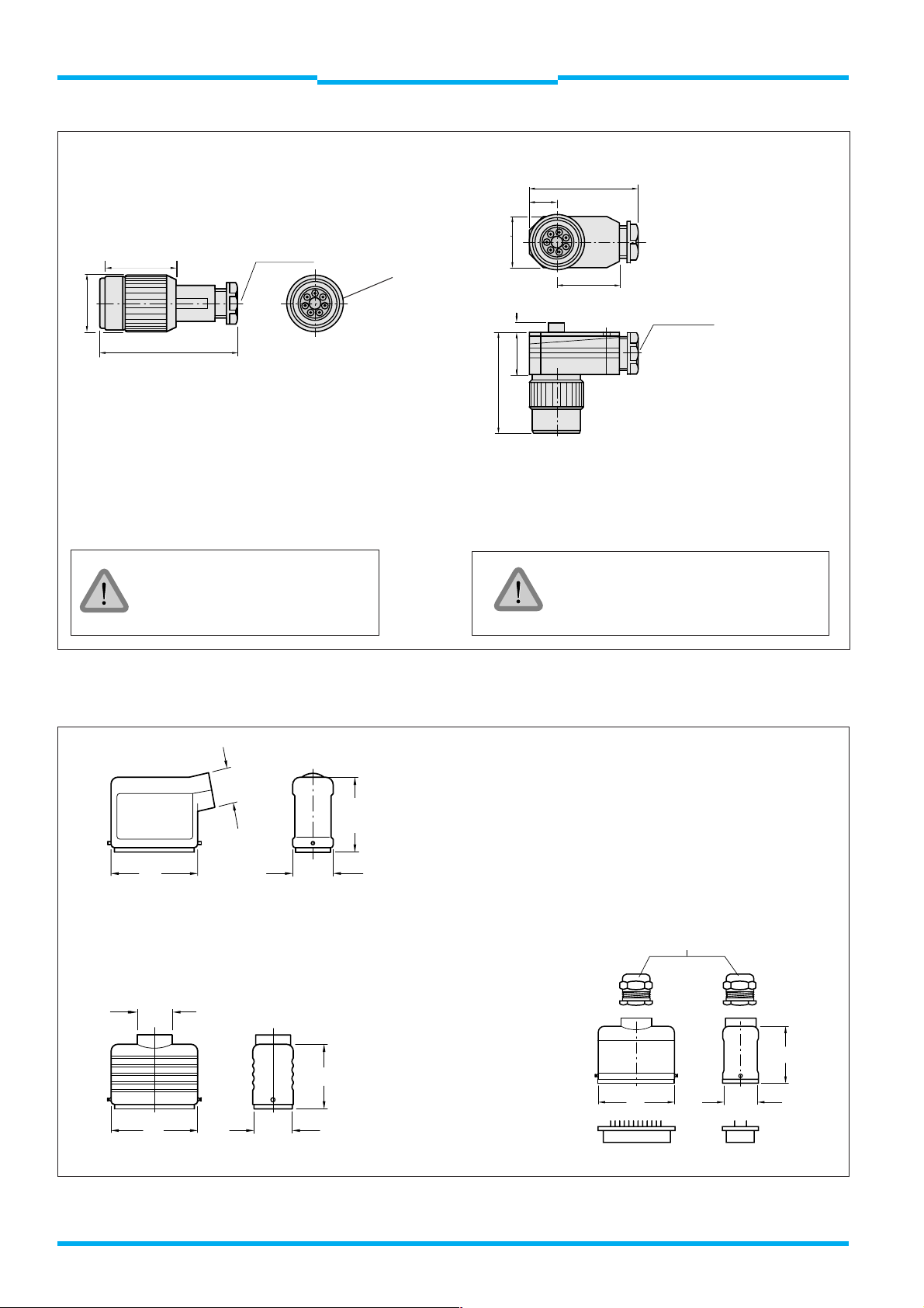
Plugs and sockets:
DIN 43 651: 6 + PE
with crimp contacts
PG 11
Fig. 20: Cable receptacles 6 + PE
PG 16
63
PG 13.5
PG 13,5
63
29.5
29,5
29,5
47
54,5
54.5
Part no. 2 019 076
Part no. 2 019 075
63
PG 13.5
PG 13,5
29,5
29.5
47
Fig. 21: Cable receptacles 15 P + PE
26
8 008 692/23-07-01 © SICK AG • Industrial Safety Systems • Germany • All rights reserved
Page 27
Technical Description
WSU 26/2 – WEU 26/2
Photoelectric Safety Switch
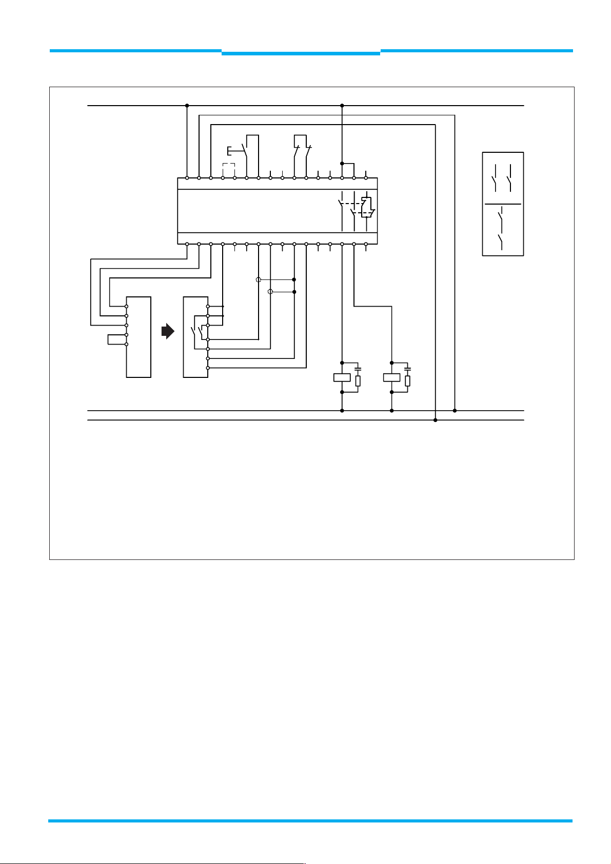
+24 V
Electrical Installation
S1
k1 k2
2
)
A1 A2 PE T0PE T13T14 X11 X12 T21 T22 X21
X22
13 2 3
N.O.
Chapter 5
XY
31
N.C.
N.O.
k1 k2
XY
WSU WEU
PE
PE
3
0V
1/2
+24V
10
Test
11
Test
LCU-X
C1 D1 PE C2 D2 PE T3 T4 C3 D3 PE C4 D4 14 24 32
1
)
1
)
1/2
+24V
4
8
9
5
3
0V
PE
PE
Z
k1
k2
Z
K2K1
0 V
PE
1
) The output contacts of the receiver must be separate and screened; screens must be connected to the negative potential, so that
any cross-connection of the cables on short circuit is detected (see 5.3 Short circuit monitoring).
2
) Potential compensation if power supply unit 0 V is not connnected with PE (VDE 0160)
x und y Connection to the machine controller to interrupt the hazardous movement. For safety reasons, the two
independent contacts
(x and y) must be inserted separately into the controller (two channel)
z If, in exceptional cases, depending on the risk assessment, the controller of the power-driven machinery is only of
a single-channel design, contact row z can be used
Fig. 22: WSU/WEU 26/2 with LCU-X safety interface
8 008 692/23-07-01 © SICK AG • Industrial Safety Systems • Germany • All rights reserved
27
Page 28
Chapter 5
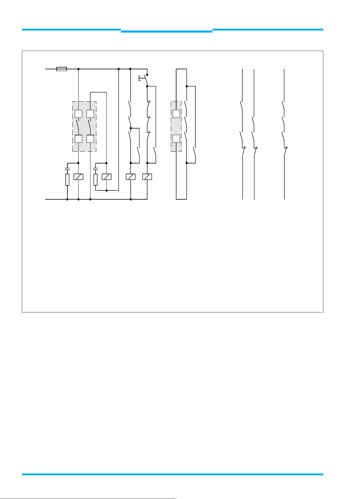
L1
F
max.4A
Electrical Installation
S
Technical Description
WSU 26/2 – WEU 26/2
Photoelectric Safety Switch
XY Z
WEU
k1
48
k2
k1
k2
WSU
10
k1
k2
k1
k2
k1
k2
1x
WSU/WEU26
59
Fu
K1
Fu
K2 K3 K4
N
K 1 to K 4 Contactors or relays with positively-driven contacts (not supplied)
Fu Spark-suppression, essential
S Command unit, e. g. pushbutton, key-operated switch etc.
Press button S to start, otherwise red LED on WEU remains lit
x und y Insert in safe machine controller to interrupt the hazardous movement. For safety reasons, the two contact rows
(x and y) must be inserted separately into the controller (two channel)
z If, in exceptional cases, depending on the risk assessment, the controller of the power-driven machinery is only
of single-channel design, contact row z can be used
k3
k3
11
k4 k4 k4
k3
k3
k3
k3
k4 k4 k4
XY Z
In this circuit example, short circuit monitoring is guaranteed by both relays K 1 (N-reference) and K 2 (L1-reference) being
connected at differing voltage levels.
An opened test contact (10 - 11 on WSU) ensures that the sender does not emit and the receiver is de-activated.
Fig. 23: Example connection with a single WSU/WEU-26/2 system
28
8 008 692/23-07-01 © SICK AG • Industrial Safety Systems • Germany • All rights reserved
Page 29
Technical Description
WSU 26/2 – WEU 26/2
Photoelectric Safety Switch
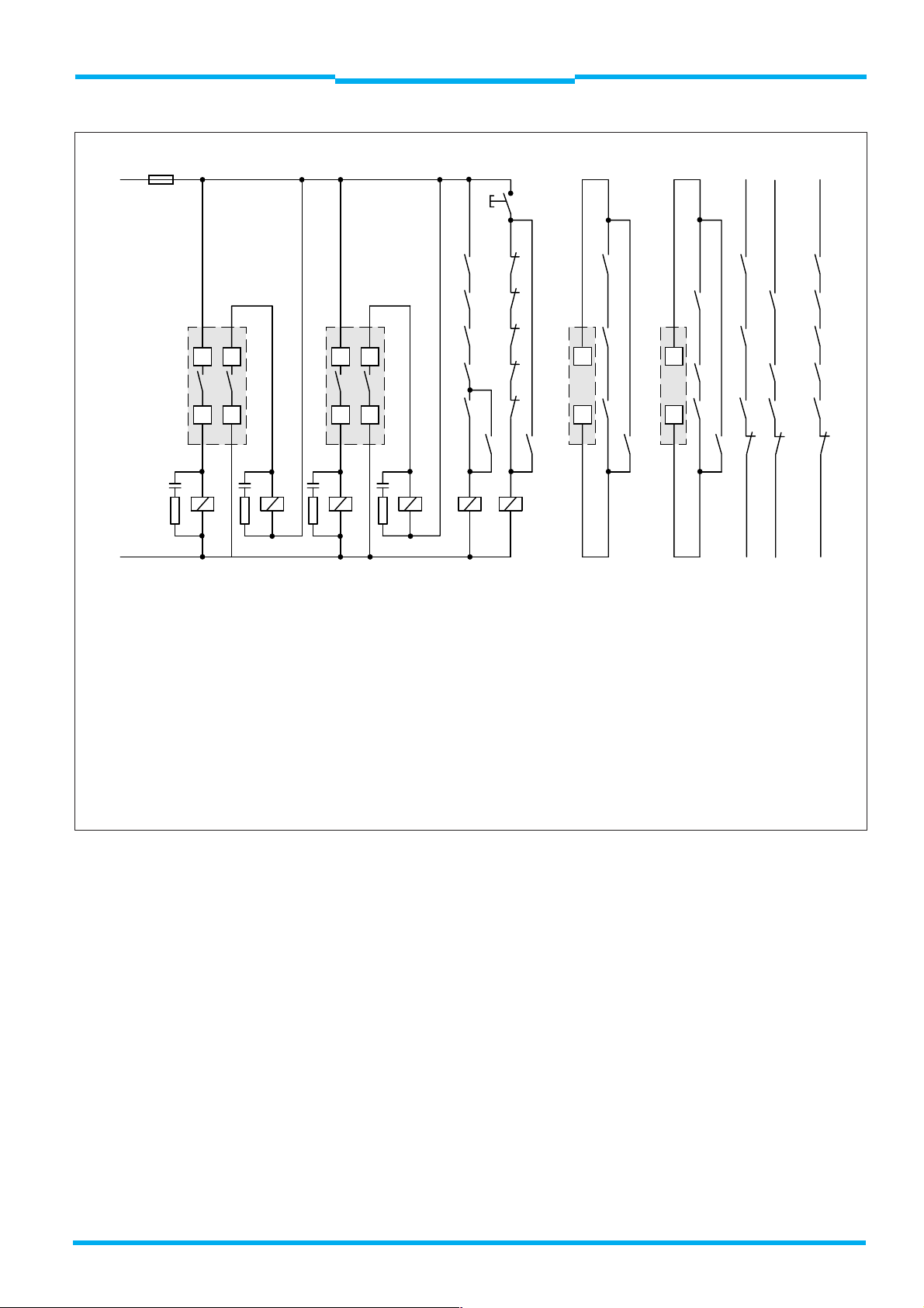
F
max.4A
L1
WEU
48
2 x
WSU/WEU 26
59
Electrical Installation
S
k1
k1
k2
k2
WEU WSU WSU
k3
k3
48
59
k4
k5
k4
k5
10
11
k1
k3
k5
10
11
XY Z
k1
k2
k3
k4
k5
k5
Chapter 5
k2
k4
k5
k1
k2
k3
k4
k5
k6 k6 k6
Fu
K1
N
K 1 to K 6 Contactors or relays with positively-guided contacts (not supplied)
Fu Spark-suppression required
S Reset unit, e. g. pushbutton, key-operated switch etc.
Press button S to start, otherwise red LED on WEU remains lit
x und y Connection to the machine controller to interrupt the hazardous movement. For safety reasons, the two contact
lines (x and y) must be inserted separately into the controller (two channel)
z If, in exceptional cases, depending on the risk assessment, the controller of the power-driven machinery is only
of a single-channel design, contact line z can be used
In this circuit example, short circuit monitoring is guaranteed by both relays K 1 (N-reference) and K 2 (L1-reference) being
connected at differing voltage levels.
An opened test contact (10 - 11 on WSU) ensures that the sender does not emit and the receiver is de-activated.
Fu Fu Fu
K2 K3 K4 K5 K6
k6 k6 k6 k6
XY Z
Fig. 24: Example connection with two WSU/WEU-26/2 systems
8 008 692/23-07-01 © SICK AG • Industrial Safety Systems • Germany • All rights reserved
29
Page 30
Chapter 5
Electrical Installation
Technical Description
WSU 26/2 – WEU 26/2
Photoelectric Safety Switch
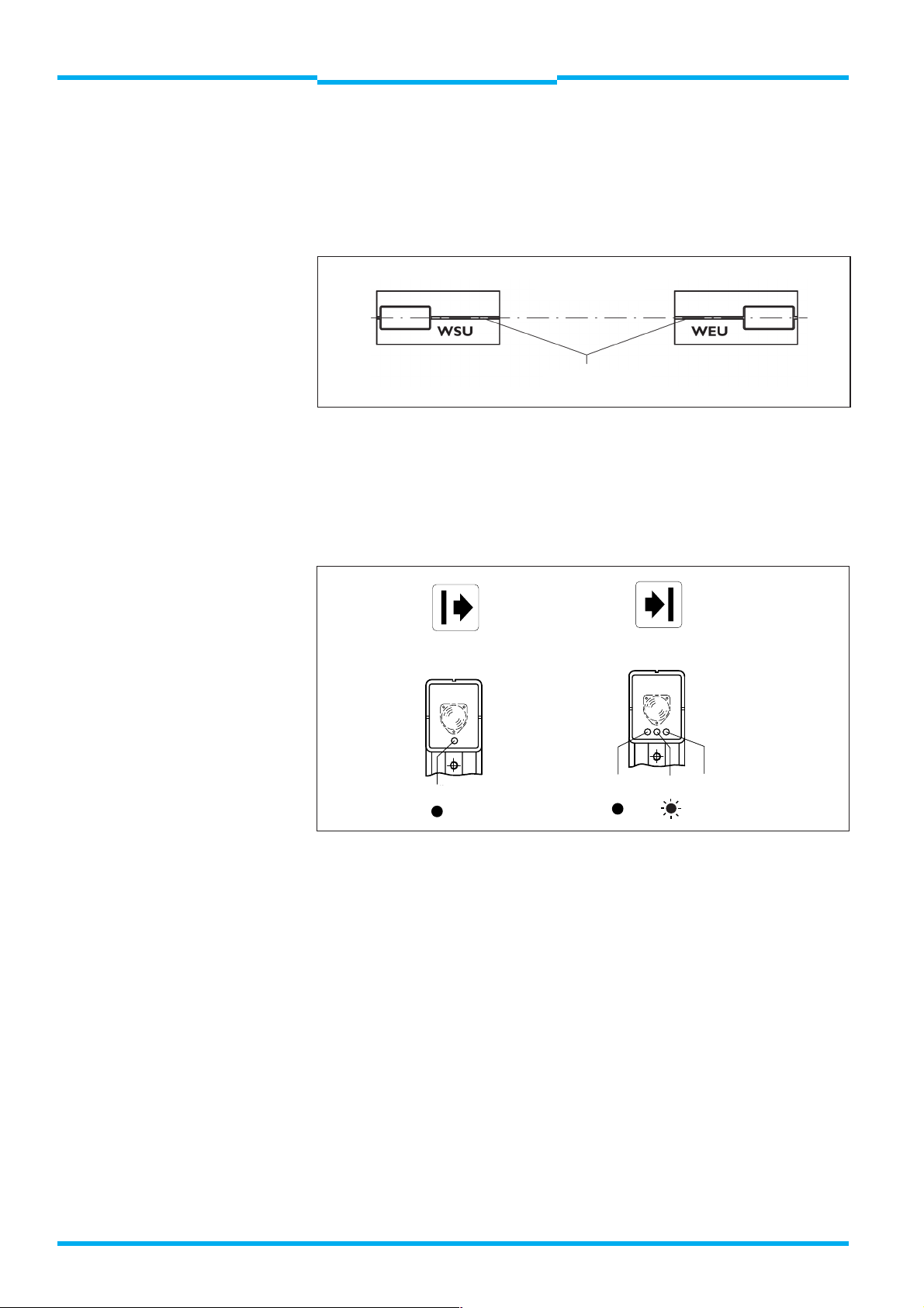
5.6 Alignment of WSU and WEU
After checking the electrical connections, lossen the fixing screws on
the WSU/WEU and roughly align the devices to each other using the
alignment sight (Fig. 25).
Optical axis
Alignment sight
Fig. 25: Alignment with the aid of the alignment sight
If the circuit example Fig. 23 or 24 is used: For further alignment keep
pressing button S or jumper terminals 10 and 11 on the WSU and switch
on the device. When this is done, the LED on the WSU (yellow LED)
lights up (Fig. 26).
Note
WSU
gelb
yellow
Fig. 26: LEDs of the WSU und WEU
WEU
grün gelb rot
green yellow red
Align the devices to each other so that the green LED on the WEU lights
up.
For optimum alignment, determine the limits of the transmission and
receiving range by pivoting the sender and receiver units horizontally
and vertically. When the device leaves its respective optical range, the
yellow LED on the WEU begins to flash. Then fix the sender and
receiver units in the middle of the determined optical range.
The yellow LED on the WEU must be permanently lit.
30
8 008 692/23-07-01 © SICK AG • Industrial Safety Systems • Germany • All rights reserved
Page 31
Technical Description
WSU 26/2 – WEU 26/2
Photoelectric Safety Switch
Electrical Installation
Chapter 5
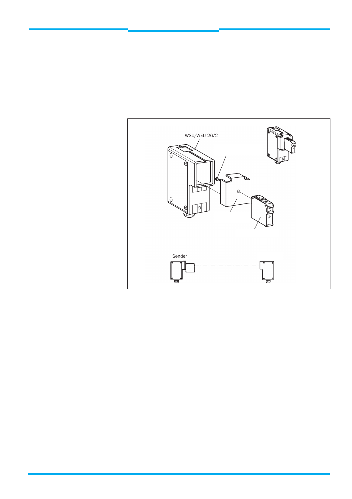
5.6.1 Alignment of WSU and WEU with alignment aid AR 60
For precise alignment of the WSU and WEU the alignment aid AR 60 is
available. The alignment aid is clamped on the front of the WSU and
WEU respectively on a bracket (Fig. 27).
The AR 60 emits a visible laser beam which exactly marks the optical
axes of WSU and WEU if they are correctly mounted.
Fixing screw
M4 x 10
Note
Adapter for
WSU/WEU 26/2
Alignment aid AR 60
Receiver
Fig. 27: Laser alignment aid AR 60 and WSU/WEU
Incorrect alignment may mean that an obstacle is not detected or that
operational safety is not achieved (Fig. 25).
8 008 692/23-07-01 © SICK AG • Industrial Safety Systems • Germany • All rights reserved
31
Page 32

Chapter 6
Test Instructions
Technical Description
WSU 26/2 – WEU 26/2
Photoelectric Safety Switch
6
Test Instructions
6.1 Pre-commissioning tests
Inspection prior to commissioning is used to confirm compliance with
Inspection of the effectiveness of the protection equipment on the
Qualified personnel must, prior to starting work, instruct the personnel
Note
Incorrect alignment may mean that an obstacle is not detected or that
operational safety is not achieved (Fig. 25).
The light beam must not be unintentionally reflected by reflecting
surfaces. Reflections can be detected as follows:
the safety requirements specified in national or international
regulations, in particular the machinery safety regulations or the
provision and use of work equipment regulations.
machine in all the operating modes in which the machine can be
placed.
operating the machine protected by the safety device. Instruction is
the responsibility of the machine operating company.
Using an object (surface: 100 x 100 mm2), break the light beam
continuously and without any gaps, starting in front of the WEU and
moving up to the WSU. In the process, the red diode on the WEU must
illuminate continuously. If this is not the case, an inspection should be
made to establish the diversion path the beam takes from the WSU to
the WEU.
This type of functionality check must be performed:
daily before commencing production;
after modifying the WSU/WEU alignment;
after all maintenance and service work carried out on the protection
system.
6.2 Regular testing of the safety device by
competent personnel
Inspection should be carried out in accordance with valid national
regulations at the intervals defined in the regulations. The objective
of these inspections is to detect any changes or modifications to the
protection device since original commissioning.
Inspections should also be carried out whenever major modifications
are made to the machine or protection equipment, as well as after readjustment or repairs in the event of damage occurring to housing,
front lens, connecting cable, etc.
32
8 008 692/23-07-01 © SICK AG • Industrial Safety Systems • Germany • All rights reserved
Page 33

Technical Description
WSU 26/2 – WEU 26/2
Photoelectric Safety Switch
WARNING
Test Instructions
Chapter 6
6.3 Daily testing of the safety module by
authorised personnel
Daily testing provides assurance that an effective personnel protection
system is in place.
It is the duty of the operator’s staff to perform testing before each
working day.
Inspection by fully covering the light beam: the red diode on the
receiver unit must illuminate.
Inspection
If the green or yellow diodes illuminate on the WEU, then no more work
may be done using the machinery. It is recommended in this case to
check the system as specified in 6.1 Pre-commissioning tests.
8 008 692/23-07-01 © SICK AG • Industrial Safety Systems • Germany • All rights reserved
33
Page 34

Chapter 7
Maintenance
Technical Description
WSU 26/2 – WEU 26/2
Photoelectric Safety Switch
7
Maintenance
Note
The system requires no maintenance. However, if the exit window is very
dirty, a clean brush should be used to remove any dust deposits. The
exit window must then be cleaned using a soft, damp cloth.
The following cleaning agents are recommended:
· Non-corrosive window cleaners
· Anti-static plastic cleaners
Do not use any cleaning agents containing alcohol.
If the module has to be opened due to faulty operation, the housing
must be cleaned thoroughly before opening to prevent dirt ingress.
Switch the power off before doing this.
34
8 008 692/23-07-01 © SICK AG • Industrial Safety Systems • Germany • All rights reserved
Page 35

Technical Description
WSU 26/2 – WEU 26/2
Photoelectric Safety Switch
Diagnostic Elements
Chapter 8
8
WSU
gelb
yellow green yellow red
Diagnostic Elements
WEU
grün gelb rot
Indicator lamp
WSU WEU Cause Inspection and rectification
yellow green yellow red
No voltage supply to WSU Check voltage
Break between terminals Check connection
10 and 11 (Test contact)
No voltage supply to WEU Check voltage on WEU
Break on relay contact, Exchange device
Relay defective
Device misaligned Re-align WSU and WEU devices
Front lens dirty Clean front lens of WSU
and WEU
WEU receiver defective Exchange device
WSU sender does not transmit Briefly switch off voltage
at WSU, then switch on (at least 1 s),
and if no function after this:
exchange WSU
Device or mirror misaligned Re-align device or
mirror
Front lens of WSU/WEU or Clean
mirror dirty
Electronics energize Switch off voltage
briefly and switch on (at least 1 s)
Spurious transmitters WEU may only respond to
WSU allocated to it
Defective electronics card Exchange device
LED off
LED illuminated
LED flashing LED no influence
8 008 692/23-07-01 © SICK AG • Industrial Safety Systems • Germany • All rights reserved
35
Page 36

Technical DataChapter 9
Technical Description
WSU 26/2 – WEU 26/2
Photoelectric Safety Switch
9
Technical Data
9.1 Overview technical data
min. typ. max.
General system data
Protective field range 0,5 m 18 m
15 m 70 m
Number of beams 1
Synchronization optical, without separate synchronization
Light beam diameter in front of WSU 23 mm
divergence angle 4°
Wave length of sender 950 nm
Protection class 1
Enclosure rating IP 65 (connection plug)
IP 67 (PG connector)
Operating mode Guard only without start and restart inhibit
Supply voltage U
Frequency AC version 48 Hz 62 Hz
1
Ripple
Voltage if power fails (20 ms) 2) 18 V
On-transition time
Transmitter unit
Test output for floating switches
Test input
Power consumption
) 1.2 V
After applying the supply voltage
of sender and receiver 1.8 s
Output current 10 mA
Reaction time on test 50 ms 60 ms
Opening time of contact for test 75 ms
Test time 150 ms
Version 24 V DC 4 W
Version 115 V AC 7 VA
Version 230 V AC 7 VA
V
19.2 V DC 24 V DC 28.8 V DC
195.5 V AC 230 V AC 253 V AC
97.75 V AC 115 V AC 126 V AC
SS
Receiver unit
Outputs Relay max. operating frequency 0.2 Hz (1 operation in 5 s)
Response time 22 ms
Current 0.02 A 2 A
Voltage 24 V DC 250 V AC
Switch-on time
36
Power (DC/AC) 144 W / 1380 VA
Mech. life expectancy (lifetime) 10
Electr. life expectancy (lifetime)
DC at 2 A current 80 x 10
AC at 2 A current 50 x 10
Normally-open contacts 10 ms
Normally-closed contacts 9 ms
Reference point for measured values: equipment plug or terminals
8 008 692/23-07-01 © SICK AG • Industrial Safety Systems • Germany • All rights reserved
7
3
3
Page 37

Technical Description
Technical Data
WSU 26/2 – WEU 26/2
Photoelectric Safety Switch
min. typ. max.
Power consumption
Version 24 V DC 6 W
Version 115 V AC 10 VA
Version 230 V AC 10 VA
Operating data
Connection Connecting cables (PG 13.5)
Connectors
Safety category Type 4
Tested to EN 61 496 part 1 and pr EN 50 100 part 2
Ambient operating temperature –25 °C +55 °C
Storage temperature –25 °C +70 °C
Air humidty (non-condensing) 15 % 95 %
Dimensions see Dimensional Drawings
Vibration resistance 5 g, 10 ... 55 Hz to IEC 68-2-6
Shock resistance 10 g, 16 ms to IEC 68-2-29
Weight
Sender unit 0.9 kg 1.3 kg
Receiver unit 1.0 kg 1.4 kg
Chapter 9
1
) The voltage must not exceed or fall below the limit values.
2
) In conformity with EN 60 204, external voltage supply for the devices must be capable of sustaining a short power
interruption of 20 ms. Suitable power supplies can be obtained from SICK as accessories (Siemens Series 6 EP 1).
8 008 692/23-07-01 © SICK AG • Industrial Safety Systems • Germany • All rights reserved
37
Page 38

Chapter 9
Technical Data
9.2 Dimensional Drawings
Technical Description
WSU 26/2 – WEU 26/2
Photoelectric Safety Switch
50
34
65
156
65
14
PG 13.5
PG13,5
Fig. 28: Dimensional Drawing WSU 26/2-xx0 and WEU 26/2-xx0
50
M6 x 8
17.5
17,5
128
15.5
15,5
116
65
95
96
116
156
65
65
14
34
M6 x 8
128
15.5
15,5
65
95
96
81
Space
ca. 50
appr. 50
Freiraum
38
Fig. 29: Dimensional Drawing WSU 26/2-xx4 and WEU 26/2-xx4
8 008 692/23-07-01 © SICK AG • Industrial Safety Systems • Germany • All rights reserved
Page 39

Technical Description
WSU 26/2 – WEU 26/2
Photoelectric Safety Switch
Technical Data
Chapter 9
156
65
65
14
50
34
M6 x 8
128
15,5
116
65
95
96
100
Space
min. 50
Freiraum
appr. 50
Fig. 30: Dimensional Drawing WSU 26/2-xx1 and -xx3 and WEU 26/2
-xx1, -xx2 and -xx3
8 008 692/23-07-01 © SICK AG • Industrial Safety Systems • Germany • All rights reserved
39
Page 40

Chapter 9
64.5
46.5
39.5
64.5
Mounting bracket WSU/WEU
Part no. 2 007 900
Technical Data
Technical Description
WSU 26/2 – WEU 26/2
Photoelectric Safety Switch
M 8 x 30 SW 13
6.5
65
20˚
60˚
51
82
65
51
6
6.5
9
9
40
43
22
M 6
Bracket for corner mirror PSK 1
Part no. 2 009 292
20
26
16.5 33.5
63
ø 20
7
58
71
M 8 x 30 SW13
M 6
67
38
96
100
Corner mirror PSK 1
Part no. 1 005 229
124
14
149
40.5
95
8.5
160
177
2.5
ø 7
14
30
12
190
160 Miroor length
10
Mirror width
105
135
156
Corner mirror PNS 105-1
Part no. 1 004 076
80
96.5
Center of mirror
surface
76
40
40.5
8.5
45˚
146.5
Corner mirror PSK 45
Part no. 5 306 053
Fig. 31: Dimensional drawing accessories
40
8 008 692/23-07-01 © SICK AG • Industrial Safety Systems • Germany • All rights reserved
69.5
8,5
8.5
63
Ø 5.5
80
Mounting set for PSK 1
Part no. 2 012 473
Page 41

Technical Description
WSU 26/2 – WEU 26/2
Photoelectric Safety Switch
Technical Data
50.5
65.565
73
12.3
50.5
65.565
Chapter 9
119
4
Snow shield
Part no. 1 003 619
140
4
Dust shield
Part no. 1 003 556
7
3
11.8
Fig. 32: Dimensional drawing snow/dust shield
27
13
20
35
15
30
250
250
135
135
3.8
Spark-suppression element
110 - 220 V Part no. 6 001 224
3.8
6.3
Spark-suppression element
48 V Part no. 6 001 225
6.3
Fig. 33: Dimensional drawing spark-suppression element
8 008 692/23-07-01 © SICK AG • Industrial Safety Systems • Germany • All rights reserved
41
Page 42
Chapter 10
At a glance: old versus new
Technical Description
WSU 26/2 – WEU 26/2
Photoelectric Safety Switch
10
At a glance: Comparison of old versus new devices
This has changed:
The optical axis of the WSU/WEU 26/2 is shifted 6 mm toward the
device connection
There are two terminals for connection of the power supply: terminal
1/2 and terminal 3
Voltage versions
230 V AC
115 V AC
24 V DC
A new adapter is required for AR 60
No fiber-optic cable version is available
An additional marking on the side identifies the middle of the beam
Die Reichweiten haben sich geändert (siehe unten)
For each range segement there is a sender and a receiver
The beam diameter has changed (see below)
Connector version: the previous connector no longer complies with
requirements for clearance and creepage distances (VDE 0160 05/88
and VDE 0110)
New front screen: may only be cleaned with plastic cleaner
The power consumption has increased (see below)
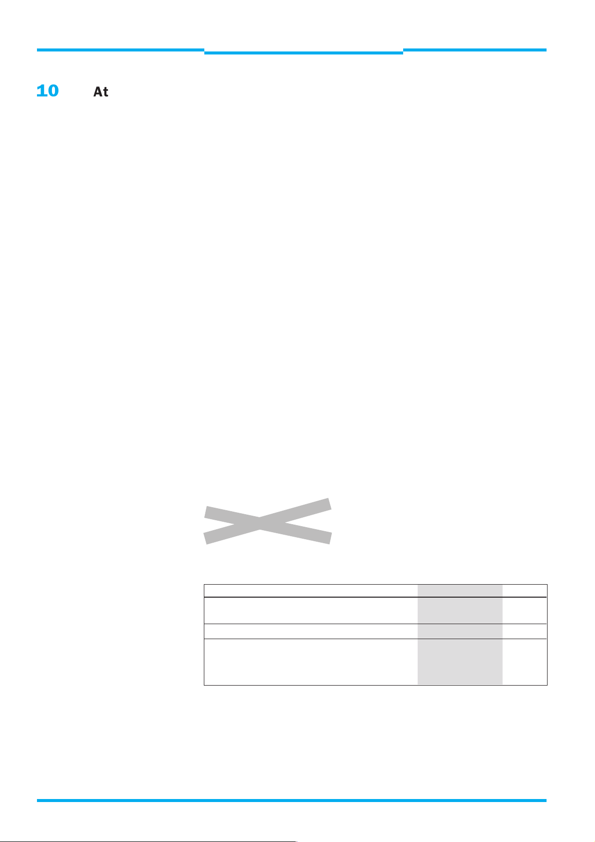
Note
Components of the (new) WSU/WEU 26/2 system cannot be combined
of the (old) WSU/WEU 26 system. When exchanging in the event of
repair please note that the following combinations are not possible:
WSU 26 with WEU 26/2
WSU 26/2 with WEU 26
Exchange in pairs.
WSU/WEU 26 WSU/WEU 26-2 Value
Scanning range 0.5 to 30 0.5 to 18 m
30 to 60 15 to 70 m
Beam diameter 33 23 m m
Power consumption
115/230 V AC 5 /7 7/10 VA
24 V DC 3/5 4/6 W
42
8 008 692/23-07-01 © SICK AG • Industrial Safety Systems • Germany • All rights reserved
Page 43
Technical Description
WSU 26/2 – WEU 26/2
Photoelectric Safety Switch
Selection table
Chapter 11
11
Voltage Scanning Termination Sender unit Receiver unit
230 V AC 0.5 to 18 mPG WSU 26/2-110 1 015 615 WEU 26/2-110 1 015 616
115 V AC 0,5 to 18 mPG WSU 26/2-120 1 015 717 WEU 26/2-120 1 015 718
Selection Table
range type Type Part no. Type Part no.
Plug WSU 26/2-111 1 015 712 WEU 26/2-111 1 015 713
Plug *) WSU 26/2-113 1 015 716 WEU 26/2-113 1 015 715
Plug *) WEU 26/2-112 1 015 714
Plug 15 P + E *) WSU 26/2-114 1 015 834 WEU 26/2-114 1 015 835
15 to 70 m PG WSU 26/2-210 1 015 731 WEU 26/2-210 1 015 743
Plug WSU 26/2-211 1 015 733 WEU 26/2-211 1 015 744
Plug *) WSU 26/2-213 1 015 736 WEU 26/2-213 1 015 748
Plug *) WEU 26/2-212 1 015 746
Plug 15 P + E *) WSU 26/2-214 1 015 840 WEU 26/2-214 1 015 841
Plug WSU 26/2-121 1 015 719 WEU 26/2-121 1 015 720
Plug *) WSU 26/2-123 1 015 723 WEU 26/2-123 1 015 722
Plug *) WEU 26/2-122 1 015 721
Plug 15 P + E *) WSU 26/2-124 1 015 836 WEU 26/2-124 1 015 837
15 to 70 m PG WSU 26/2-220 1 015 738 WEU 26/2-220 1 015 749
Plug WSU 26/2-221 1 015 740 WEU 26/2-221 1 015 750
Plug *) WSU 26/2-223 1 015 737 WEU 26/2-223 1 015 505
WEU 26/2-222 1 015 751
Plug 15 P + E *) WSU 26/2-224 1 015 842 WEU 26/2-224 1 015 843
24 V DC 0,5 to 18 m PG WSU 26/2-130 1 015 724 WEU 26/2-130 1 015 725
Stecker WSU 26/2-131 1 015 726 WEU 26/2-131 1 015 727
Stecker *) WSU 26/2-133 1 015 730 WEU 26/2-133 1 015 729
Stecker *) WSU 26/2-231 1 015 747 WEU 26/2-231 1 015 753
Plug *) WSU 26/2-233 1 015 739 WEU 26/2-233 1 015 755
Plug *) WEU 26/2-232 1 015 754
Plug 15 P + E *) WSU 26/2-234 1 015 844 WEU 26/2-234 1 015 845
*) See electrical wiring diagram
Selection of plug variant WSU/WEU
Since 1989 VDE 0160 05/88 and VDE 0110 have stipulated doubled
WARNING
clearance and creepage distances. In the following cases the necessary
clearance and creepage distance of the 6 PE Hirschmann connecting
plug on the WEU are not met:
Supply voltage Voltage at WEU Remarks
WEU output relays
230 V AC 230 V AC Only in case of separated
circuits/phases
230 V AC 24 V DC –
24 V DC 230 V AC –
In order to meet the VDE requirements for clearance and creepage
distances in theses cases, the square 15-pin + PE plug must be used.
8 008 692/23-07-01 © SICK AG • Industrial Safety Systems • Germany • All rights reserved
43
Page 44

Chapter 11
Selection Table
WSU 26/2 – WEU 26/2
Photoelectric Safety Switch
11.1 Conversion list
WSU to be New type 26/2
replaced Scanning range 0.5 to 18 m Scanning range 15 to 70 m
WSU 26-110 WSU 26/2-110 1 015 615 WSU 26/2-210 1 015 731
WSU 26-111 WSU 26/2-111 1 015 712 WSU 26/2-211 1 015 733
WSU 26-112 WSU 26/2-113 1 015 716 WSU 26/2-213 1 015 736
WSU 26-120 WSU 26/2-120 1 015 717 WSU 26/2-220 1 015 738
WSU 26-121 WSU 26/2-121 1 015 719 WSU 26/2-221 1 015 740
WSU 26-130 WSU 26/2-130 1 015 724 WSU 26/2-230 1 015 745
old
WSU 26-131 WSU 26/2-131 1 015 726 WSU 26/2-231 1 015 747
WSU 26-132 WSU 26/2-133 1 015 730 WSU 26/2-233 1 015 739
WSU 26-210 WSU 26/2-210 1 015 731
WSU 26-211 WSU 26/2-211 1 015 733
WSU 26-212 WSU 26/2-213 1 015 736
WSU 26-220 WSU 26/2-220 1 015 738
WSU 26-221 WSU 26/2-221 1 015 740
WSU 26-230 WSU 26/2-230 1 015 745
WSU 26-231 WSU 26/2-231 1 015 747
WSU 26-232 WSU 26/2-233 1 015 739
Technical Description
WEU to be New type 26/2
replaced Scanning range 0.5 to 18 m Scanning range 15 to 70 m
WEU 26-710 WEU 26/2-110 1 015 616 WEU 26/2-210 1 015 743
WEU 26-712 WEU 26/2-112 1 015 713 WEU 26/2-211 1 015 744
WEU 26-713 WEU 26/2-113 1 015 715 WEU 26/2-213 1 015 748
WEU 26-720 WEU 26/2-120 1 015 718 WEU 26/2-220 1 015 749
WEU 26-730 WEU 26/2-130 1 015 725 WEU 26/2-230 1 015 504
old
WEU 26-731 WEU 26/2-131 1 015 727 WEU 26/2-231 1 015 753
WEU 26-732 WEU 26/2-132 1 015 728 WEU 26/2-232 1 015 754
WEU 26-733 WEU 26/2-133 1 015 729 WEU 26/2-233 1 015 755
44
8 008 692/23-07-01 © SICK AG • Industrial Safety Systems • Germany • All rights reserved
Page 45

Technical Description
WSU 26/2 – WEU 26/2
Photoelectric Safety Switch
Selection Table Accessories
Chapter 12
12
Selection Table Accessories
Description Part no.
Alignment aid AR 60, complete 1 015 741
Adapter for alignment aid AR 60 4 031 156
Mounting bracket for WSU/WEU 2 007 900
Corner mirror PSK 1, for scanning range 0.5 to 18 m 1 005 229
Mounting set for PSK 1 2 012 473
Hinged bracket for corner mirror PSK 1 (1 piece) 2 009 292
Corner mirror PNS 105-1,
for scanning range 15 to 70 m 1 004 076
Corner mirror PSK 45 5 306 053
Cable receptacle, straight, 6 + PE (plastic) 6 006 612
Cable receptacle, angled (plastic) 6 006 613
Cable receptacle 15 P + E, lateral cable outlet,
PG 16 2 019 076
Cable receptacle 15 P + E, lateral cable outlet,
PG 13.5 2 019 075
Spark-suppression element RC-A
0,22 mF + 220 W (115 to 230 V) 6 001 224
Spark-suppression element RC-AD
2,2 mF + 100 W (24 V) 6 001 225
Switching amplifier LCU-X 24 V DC 1 013 410
PG-cable gland PG 21 5 305 978
for use of 2 cables with PNOZ 8
PG extension PG 13.5 to PG 21 5 306 052
for use of 2 cables with PNOZ 8
Dust shield 1 003 556
Snow shield 1 003 619
8 008 692/23-07-01 © SICK AG • Industrial Safety Systems • Germany • All rights reserved
45
Page 46

Chapter 13
Checklist
Technical Description
WSU 26/2 – WEU 26/2
Photoelectric Safety Switch
13
Maßbilder Spiegel
Checklist
Checklist for machine manufacturer/installer for the
installation of Electro Sensitive Protective Equipment (ESPE)
Dependent upon the application, the checks listed below are a minimum when placing an ESPE
into operation for the first time.
For reference purposes the list should be retained or stored with the machine documents.
1. Are the relevant safety standards incorporated into the machine build?
Will they satisfy the Regulations? Yes No
2. Are the standards listed in the Declaration of Conformity? Yes No
3. Is the ESPE the correct type and interfaced to the correct category? Yes No
4. Is access to the danger zone/point of danger only possible through
the ESPE? Yes No
5. Are measures in place to prevent standing between the ESPE and
the danger zone? If so, are these measures secured against removal? Yes l No
6. Has the overall machine stopping time been checked and
documented? Yes No
7. Is the resultant safety distance observed between the danger point
and the ESPE? Yes No
8. Is the ESPE correctly fixed and secured against movement after
setting in its fixed position? Yes No
9. Are the required protection measures against electric shock in place? Yes No
10. Is the re-set/re-start switch for the ESPE installed and fitted to the
correct standard? Yes No
11. Are the OSSDs of the ESPE connected in accordance with the machine
circuit diagram? Yes No
12. Have the protective functions been inspected in accordance with the
inspection instructions of this document? Yes No
13. Are the protective functions effective in every setting of the operating
mode switch? Yes No
14. Are the switching elements controlled by the ESPE, e. g. contactors,
valves monitored? Yes No
15. Is the ESPE effective during the entire hazardous state? Yes No
16. Is the hazardous state ended when the ESPE is switched on or off,
as well as upon changing operation modes or on switching over to
another protective device? Yes No
17. Is the Daily Check Requirement sign positioned in a place visible to
the operator? Yes No
46
This checklist does not replace the initial commissioning of regular inspections by qualified
personnel.
8 008 692/23-07-01 © SICK AG • Industrial Safety Systems • Germany • All rights reserved
Page 47

Technical Description
WSU 26/2 – WEU 26/2
Photoelectric Safety Switch
8 008 692/23-07-01 © SICK AG • Industrial Safety Systems • Germany • All rights reserved
47
Page 48

8 008 692/23-07-01 · KW/KF · Printed in Germany (03.02)
·
Subject to change without prior notice GB 8.02 TB
SICK AG · Industrial Safety Systems · P.O. Box 310 · 79177 Waldkirch · Deutschland
Phone +49 76 81 2 02 0 · Fax +49 76 81 2 02 38 15 · www.sick.de
Your contacts:
A ustralia
Phone +61 3 94 9741 00
008 33 48 02 – toll free
Fax +61 3 94971187
A ustria
Phone +43 2 23 66 22 88-0
Fax +43 2 23 66 22 88-5
Belgium/Luxembourg
Phone +32 24 66 55 66
Fax +32 24 63 31 04
Brazil
Phone +55 11 55 6126 83
Fax +55 11 55 35 41 53
China/Hong Kong
Phone +8 52 27 63 69 66
Fax +8 52 2763 6311
Czech Republik
Phone +42 02 578 10 561
Fax +42 02 578 10 559
Denmark
Phone +45 45 82 64 00
Fax +45 45 82 64 01
Finland
Phone +3 58 9-728 85 00
Fax +3 58 9-72 88 5055
F rance
Phone +33 1 64 62 35 00
Fax +33 1 64 62 35 77
Germany
Phone +49 2 11 53 01 0
Fax +49 2 11 53 01 100
Great Britain
Phone +44 17 27-83 11 21
Fax +44 17 27-85 67 67
Italy
Phone +39 02 92 14 20 62
Fax +39 02 92 14 20 67
Japan
Phone +813 33 58 13 41
Fax +8 13 33 58 05 86
Netherlands
Phone +31 30 229 25 44
Fax +31 30 229 39 94
Norway
Phone +47 6756 7500
Fax +47 67 56 6610
Poland
Phone +48 22 8 3740 50
Fax +48 22 8 37 43 88
Singapore
Phone +65 7 44 37 32
Fax +65 8 417747
Spain
Phone +34 93 4 80 31 00
Fax +34 93 4 73 44 69
Sweden
Phone +46 8 6 80 64 50
Fax +46 8 7 10 18 75
Switzerland
Phone +41 4 16 19 29 39
Fax +41 4 16192921
Taiwan
Phone +88 62 23 65 62 92
Fax +88 62 23 68 73 97
USA
Phone +1(952) 9 41-67 80
Fax+1(952) 9 41-92 87
Representatives and agencies
in all major industrial nations.
 Loading...