

Page 1
O P E R A T ING INS T R U CT I ONS
VMS4200 / VMS5200
Track and trace systems
Page 2

2
8022965/2018-08-16|SICK
O RI G IN A L O P ER A TI N G I NS T RU C TI O NS | VMS4200 / VMS5200 volume measurement system
Subject to change without notice
Product described
Product name: VMS4200 / VMS5200
Document identification
Title: VMS4200 / VMS5200 operating instructions
Part number: 8022965
Status: 2018-08-16
Manufacturer
SICK AG
Erwin-Sick-Str. 1 · 79183 Waldkirch · Germany
Trademarks
IBM is a trademark of the International Business Machine Corporation.
MS-DOS is a trademark of the Microsoft Corporation.
Windows is a trademark of the Microsoft Corporation.
Other product names in this document may also be trademarks and are only
used here for identification purposes.
Original documents
The German version 8022964 of this document is an original SICK AG
document.
SICK AG does not assume liability for the correctness of any unauthorized
translation.
In case of doubt, contact SICK AG or your local agency.
Legal notes
Subject to change without notice
© SICK AG. All rights reserved
Page 3

CONTENTS
3
8022965/2018-08-16|SICK
Subject to change without notice
O RI G IN A L O P ER A TI N G I NS T RU C TI O NS | VMS4200 / VMS5200 volume measurement system
Content
1 About this document ............................................................................................ 6
1.1 Purpose of this document ........................................................................ 6
1.2 Abbreviations used................................................................................... 6
1.3 Symbols used ........................................................................................... 6
2 On safety ................................................................................................................ 7
2.1 Qualified safety personnel ....................................................................... 7
2.2 Intended use ............................................................................................. 7
2.3 General safety notes and protective measures ..................................... 8
2.3.1 Safety notes and symbols ........................................................ 8
2.3.2 General safety notes ................................................................. 9
2.3.3 Additional operating instructions ............................................. 9
2.3.4 Dangers connected with handling of the system .................. 10
2.4 RoHS Directive........................................................................................ 14
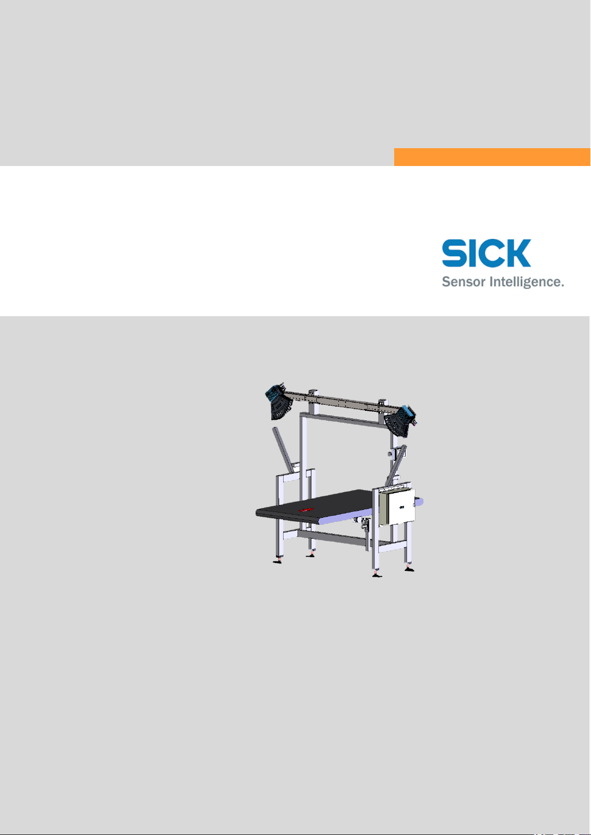
3 System description ............................................................................................. 15
3.1 Scope of delivery .................................................................................... 15
3.2 Structure of the volume measurement system .................................... 16
3.2.1 System components ............................................................... 16
3.2.2 Expanding the system with a reading station ........................ 19
3.3 Operating principle of the volume measurement system .................... 20
3.3.1 Operating modes ..................................................................... 20
3.3.2 Calculating the volume ........................................................... 22
3.3.3 Data processing and data output .......................................... 24
3.4 Nominal value conditions ...................................................................... 26
3.4.1 Fixed scale values ................................................................... 26
3.4.2 Dynamic scale value switchover ............................................ 29
3.5 System requirements ............................................................................. 30
3.5.1 Required interfaces ................................................................ 30
3.5.2 Requirements at the operation site ....................................... 30
3.5.3 Object requirements ............................................................... 30
3.5.4 Conveying equipment requirements ...................................... 30
3.5.5 Mounting requirements .......................................................... 31
3.6 Officially verifiable operation ................................................................. 34
3.6.1 Information labels ................................................................... 34
3.6.2 Security seal ............................................................................ 38
3.6.3 SD card with alibi memory ...................................................... 41
3.6.4 LFT display ............................................................................... 43
3.6.5 Test instructions for market surveillance .............................. 46
3.7 Status indicators .................................................................................... 50
3.7.1 LMS4xxx volume measurement devices ............................... 50
3.7.2 Status indicators on the SIM2000 controller ........................ 50
3.8 Interfaces ................................................................................................ 51
4 Mounting ............................................................................................................. 52
4.1 Mounting volume measurement devices ............................................. 52
4.1.1 Assembling the profiles of the telescopic tube ..................... 53
4.1.2 Mounting telescopic tube to the frame ................................. 53
4.1.3 Mounting the volume measurement devices to the retaining
plates ....................................................................................... 53
4.2 Mounting the measuring wheel encoder .............................................. 55
Page 4

CONTENTS
4
8022965/2018-08-16|SICK
O RI G IN A L O P ER A TI N G I NS T RU C TI O NS | VMS4200 / VMS5200 volume measurement system
Subject to change without notice
4.3 Mounting the photoelectric retro-reflective sensor and reflector
(optional) ................................................................................................ 56
4.4 Mounting the cabinet ............................................................................. 57
4.5 Dismantling the measurement system ................................................. 58
5 Electrical installation ......................................................................................... 59
5.1 Connection overview .............................................................................. 61
5.2 Connecting to the voltage supply .......................................................... 62
5.3 Connection for the Ethernet switch (set up at the factory) .................. 63
5.4 Connecting the volume measurement devices .................................... 64
5.5 Connecting the LFT display ................................................................... 65
5.6 Connection for the measuring wheel encoder ..................................... 66
5.7 Connection for the photoelectric retro-reflective sensor (optional) .... 67
5.8 Connecting to the customer interface .................................................. 68
6 Commissioning ................................................................................................... 69
6.1 Switching on the system ........................................................................ 69
6.2 Configuring the system with SOPAS ...................................................... 70
6.2.1 Installing SOPAS ET ................................................................ 70
6.2.2 Allocating IP addresses .......................................................... 72
6.2.3 Opening the configuration interface ...................................... 78
6.2.4 Logging into the device ........................................................... 80
6.2.5 Saving the parameters permanently ..................................... 80
7 Maintenance and repairs .................................................................................. 81
7.1 Monitoring and cleaning work ............................................................... 82
7.1.1 Control measurements ........................................................... 82
7.1.2 Visual inspection ..................................................................... 83
7.1.3 Cleaning the volume measurement devices ......................... 84
7.1.4 Checking the measuring wheel encoder components ......... 85
7.1.5 Cleaning the photoelectric retro-reflective sensor ................ 86
7.1.6 Keeping the cabinets cool ...................................................... 86
7.2 Replacing components .......................................................................... 88
7.2.1 Replacing the volume measuring device .............................. 88
7.2.2 Replacing the measuring wheel encoder .............................. 90
7.2.3 Replacing the photoelectric retro-reflective sensor .............. 91
8 Fault diagnosis ................................................................................................... 92
8.1 Response to errors................................................................................. 92
8.2 SICK Support .......................................................................................... 92
8.3 Fault indicators of the components ...................................................... 92
8.4 Troubleshooting for the SIC2000.......................................................... 93
8.4.1 Checking the trigger ................................................................ 93
8.4.2 Checking the incremental encoder ........................................ 94
8.4.3 Checking CAN cabling ............................................................. 95
8.5 Faults during operation ......................................................................... 96
8.6 Detailed fault analysis ........................................................................... 97
8.6.1 The status log .......................................................................... 97
8.6.2 Checking the status log with SOPAS ...................................... 97
9 Appendix .............................................................................................................. 98
9.1 Technical data ........................................................................................ 98
9.1.1 Data sheet ............................................................................... 98
Page 5

CONTENTS
5
8022965/2018-08-16|SICK
Subject to change without notice
O RI G IN A L O P ER A TI N G I NS T RU C TI O NS | VMS4200 / VMS5200 volume measurement system
9.1.2 Dimensional drawings of the volume measurement
devices ..................................................................................... 99
9.2 Compliance with EU directives ............................................................ 100
10 Disposal ............................................................................................................. 101
Page 6

1 ABOUT THIS DOCUMENT
6
8022965/2018-08-16|SICK
O RI G IN A L O P ER A TI N G I NS T RU C TI O NS | VMS4200 / VMS5200 volume measurement system
Subject to change without notice
1 About this document
Please read this chapter carefully before you begin working with this documentation and
the VMS4200 / VMS5200.
1.1 Purpose of this document
These operating instructions guide technical personnel in the safe mounting,
parameterization, electrical installation, commissioning, operation, and maintenance of
the VMS4200 / VMS5200 volume measurement system.
1.2 Abbreviations used
Controller Area Network = standardized fieldbus system that uses a message-based
data exchange protocol
Light emitting diode
Laser measurement scanner = 2D LiDAR sensor from SICK AG
Random Access Memory = direct-access volatile memory
SICK OPEN PORTAL for APPLICATION and SYSTEMS Engineering Tool = software for
configuring the VMS4200 / VMS5200
Volume Measurement System from SICK AG
1.3 Symbols used
Recommendations are designed to assist you in the decision-making process with respect
to the use of a certain function or technical measure.
Notes provide information about the features of a device, application tips, or other useful
information.
Instructions requiring specific action are indicated by an arrow. Carefully read and follow
the instructions for action.
LED icons describe the status of a diagnostics LED. Examples:
The LED is illuminated continuously.
The LED is flashing.
The LED is off.
CAN
LED
LMS
RAM
SOPAS ET
VMS
Recommendation
Note
,
Page 7
ON SAFETY 2
7
8022965/2018-08-16|SICK
Subject to change without notice
O RI G IN A L O P ER A TI N G I NS T RU C TI O NS | VMS4200 / VMS5200 volume measurement system
2 On safety
This chapter concerns your own safety and the safety of the system operator.
▸
Please read this chapter carefully before you begin working with the volume
measurement system.
2.1 Qualified safety personnel
The volume measurement system must only be mounted, commissioned, and maintained
by properly qualified safety personnel.
The following qualifications are necessary for the various tasks:
Activities
Qualification
Mounting and
maintenance
Practical technical training
Knowledge of the current safety regulations in the workplace
Electrical installation
and device replacement
Practical electrical training
Knowledge of current electrical safety regulations
Knowledge of device control and operation in the particular
application concerned (e.g., conveying system, etc.)
Commissioning,
operation, and
configuration
Knowledge of the operation and control of the devices in their
particular application (e.g., conveying system)
Knowledge concerning the software and hardware environment of
the particular application concerned (e.g., conveying system)
Basic knowledge of the Windows operating system used
Basic knowledge of data transmission
Basic knowledge of the design and setup (addressing) of Ethernet
connections when connecting the system to the Ethernet
Table 1Qualified safety personnel
2.2 Intended use
The VMS4200 / VMS5200 volume measurement system is used to measure cubic and
non-cubic objects on flat conveying systems in industrial environments.
The objects must be dimensionally stable, opaque, and non-reflective.
The VMS4200 / VMS5200 determines length, width, and height, and can calculate the
volume of the smallest enveloping cuboid (box volume) using these values.
All measurement results are transferred to the customer network via the data interface of
the SIM2000 control unit.
The VMS5200 volume measurement system is verified as legal for trade and can be used
for billing purposes.
WARNING
Danger due to intended use
Intended use of the system can lead to danger to the life and limb of persons and damage
to the plant in which the system is integrated.
▸
The system should only be used in line with the intended use.
▸
The system should not be used outdoors or in an explosion-protected environment.
Page 8
2 ON SAFETY
8
8022965/2018-08-16|SICK
O RI G IN A L O P ER A TI N G I NS T RU C TI O NS | VMS4200 / VMS5200 volume measurement system
Subject to change without notice
2.3 General safety notes and protective measures
2.3.1 Safety notes and symbols
The following safety and hazard information is for your own safety, for the safety of third
parties, and for the protection of the volume measurement system. You should therefore
observe them at all times.
DANGER
Denotes an immediate hazard that may result in severe to fatal injuries.
The symbol shown on the left-hand side of the note refers to the type of hazard in
question (the example here shows a risk of injury resulting from electrical current).
WARNING
Denotes a potentially dangerous situation that may result in severe to fatal injuries.
The symbol shown on the left-hand side of the note refers to the type of hazard in
question (the example here shows a risk of injury resulting from falling components).
CAUTION
Caution note
Denotes a potentially dangerous situation that may result in minor personal injury or
possible material damage.
The symbol shown on the left-hand side of the note refers to the type of hazard in
question (the example here shows a risk of damage to the eye by laser beams).
NOTE
Denotes a potential risk of damage or functional impairment of the device or the devices
connected to it.
This symbol refers to supplementary technical documentation.
Page 9
ON SAFETY 2
9
8022965/2018-08-16|SICK
Subject to change without notice
O RI G IN A L O P ER A TI N G I NS T RU C TI O NS | VMS4200 / VMS5200 volume measurement system
2.3.2 General safety notes
General, recognized safety-related rules and regulations were taken into account in the
design and manufacture of the volume measurement system. However, risks for the user
resulting from the system cannot be completely ruled out. The safety notes below must
therefore be observed.
WARNING
Observe the following to ensure the safe use of the system as intended.
The notes in this documentation must be complied with.
All official and statutory regulations governing the operation of the system must be
complied with.
The national and international legal specifications apply to the installation and use of
the system, to its commissioning, and to recurring technical inspections, in particular:
– The accident prevention regulations and work safety regulations
– Any other relevant safety regulations
The manufacturer and user of the system are responsible for coordinating and
complying with all applicable safety specifications and regulations in cooperation with
the relevant authorities.
The checks must be carried out by qualified safety personnel or specially qualified and
authorized personnel, and must be recorded and documented to ensure that the tests
can be reconstructed and retraced at any time.
These operating instructions must be made available to the operator of the system.
The system operator must be instructed by qualified safety personnel and must read
the operating instructions.
Maintenance and repair work may only be performed by trained and authorized SICK
AG service technicians or qualified safety personnel of the customer.
2.3.3 Additional operating instructions
Other operating instructions of the individual components are enclosed along with this
system description.
▸
When working on or with the system components, please observe the notes in the
relevant operating instructions.
Page 10
2 ON SAFETY
10
8022965/2018-08-16|SICK
O RI G IN A L O P ER A TI N G I NS T RU C TI O NS | VMS4200 / VMS5200 volume measurement system
Subject to change without notice
2.3.4 Dangers connected with handling of the system
Awareness of potential hazardous points in the system will help you to work in a safer
manner and thus prevent accidents.
Dangers due to electrical current
DANGER
Risk of injury due to electrical current
Electrical voltage can cause severe personal injury or death by electric shock.
▸
Electrical installation work may only be carried out by electrically qualified persons.
▸
Be sure to disconnect the voltage supply before attaching or detaching any electrical
connections.
▸
Only connect the system to a voltage source that meets the technical requirements.
▸
National and regional regulations must be complied with.
▸
Safety requirements relating to work on electrical systems must be complied with.
DANGER
Dangerous equipotential bonding currents
As a result of possible equipotential bonding currents between the device and other
earthing devices in the system, faulty earthing of the device can give rise to the following
dangers and faults:
Dangerous voltages on the metal housing, e.g., of the laser scanner.
Incorrect functioning of or irreparable damage to the devices
Damage/irreparable damage to the cable shields due to heating and cable fires.
Measures
▸
Only skilled electricians should be permitted to carry out work on the electrical system.
▸
Ensure that the ground potential is the same at all grounding points.
▸
If the cable insulation is damaged, disconnect the voltage supply immediately and have
the damage repaired.
▸
Where local conditions are unfavorable and thus do not meet conditions for a safe
earthing method (same ground potential at all grounding points), take measures in
accordance with the following explanations.
Page 11
ON SAFETY 2
11
8022965/2018-08-16|SICK
Subject to change without notice
O RI G IN A L O P ER A TI N G I NS T RU C TI O NS | VMS4200 / VMS5200 volume measurement system
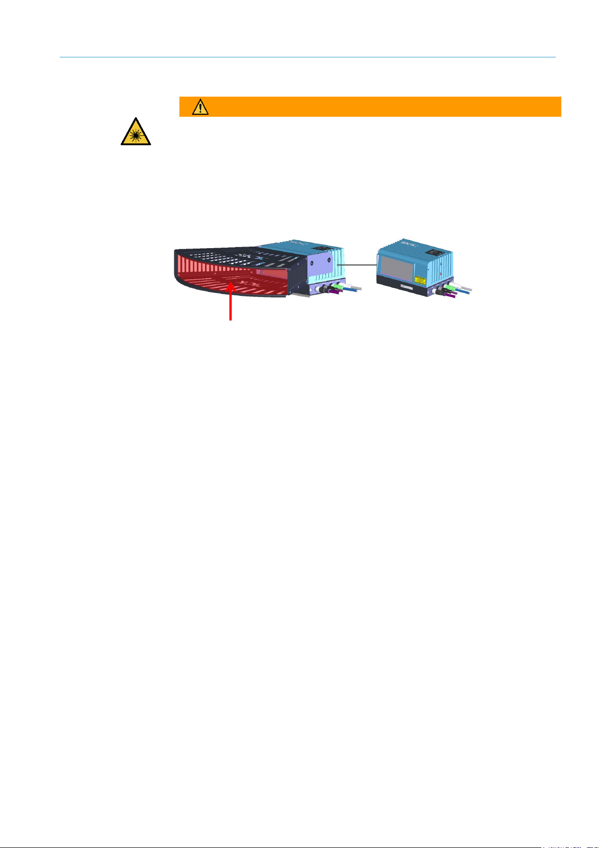
Danger due to laser light
WARNING
Damage to the eye by laser beams
The LMS4xxx volume measurement devices work with red, class-2 lasers.
The human eye is not at risk when briefly exposed to the radiation for up to 0.25 seconds.
Exposure to the laser beam for longer periods of time may cause damage to the retina.
The laser radiation is harmless to human skin.
The laser output aperture is the front screen of the devices.
Fig.1: Laser output aperture of the laser scanner
▸
Do not look into the laser beam intentionally.
▸
Never point the laser beam at people’s eyes.
▸
If it is not possible to avoid looking directly into the laser beam, e.g., during
commissioning and maintenance work, suitable eye protection must be worn.
▸
Avoid laser beam reflections caused by reflective surfaces. Be particularly careful
during mounting and alignment work.
▸
Do not open the housing. Opening the housing will not switch off the laser. Opening the
housing may increase the level of risk.
▸
Applicable national regulations regarding laser protection must be observed.
Measures
Page 12
2 ON SAFETY
12
8022965/2018-08-16|SICK
O RI G IN A L O P ER A TI N G I NS T RU C TI O NS | VMS4200 / VMS5200 volume measurement system
Subject to change without notice
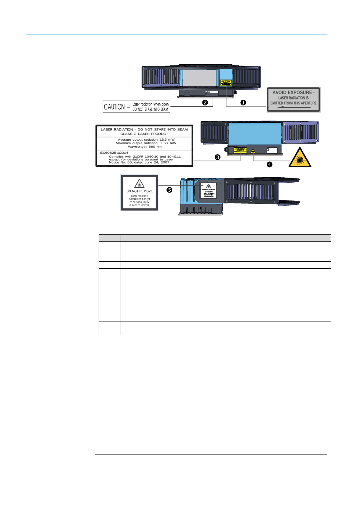
The laser warning labels are located on the respective devices.
Fig.2: Laser warning labels
No.
Meaning
1
Avoid exposure – Laser radiation is emitted from this aperture.
Laser output aperture corresponds to the front screen at the height of the position
shown.
2
Caution – Laser radiation when open. Do not stare into beam.
3
Laser radiation – Do not stare into beam. Class 2 laser product
Average output radiation: 13.5 mW
Maximum output radiation: 27 mW
Wavelength: 660 nm
IEC60825-1:2014
Complies with 21CFR 1040.10 and 1040.11 except for deviations pursuant to Laser
Notice No. 50, dated June 24, 2007.
4
Warning symbol: Laser radiation
5
Do not remove – Laser radiation hazard and danger of personal injury in case of
removal.
“RADIATION – DO NOT STARE INTO BEAM” is to be replaced with a warning label in a
language that the operators of the system understand. Laser warning labels in German
and French are included in the scope of delivery.
If the device is installed in a system/casing in way that means that the warning labels
are covered, other warning labels (not included with delivery) must be attached to the
system/casing next to the laser output aperture.
When operating with the trigger, the laser diode is switched on by the switch-on signal
and switched off again by the deactivation signal. When free output of measured
values is set, the laser diode is continuously on.
The device automatically monitors beam generation and automatically shuts down the
laser diode in the event of irregularities. If this happens, the red “Status” LED lights up.
The device stops sending measured values and an entry is added to the error memory.
Laser warning labels
Notes
Page 13
ON SAFETY 2
13
8022965/2018-08-16|SICK
Subject to change without notice
O RI G IN A L O P ER A TI N G I NS T RU C TI O NS | VMS4200 / VMS5200 volume measurement system
Dangers when mounting
WARNING
Risk of injury due to components tipping over
If profiles of the mounting frame have been upended, they could possibly tip over during
disassembly.
▸
Do not do mounting work alone.
▸
Ask a second person to assist you. during mounting where necessary.
▸
Wear safety shoes.
Risks during operation
WARNING
Risk of injury and/or material damage caused by incorrect operation.
Risk of injury and/or material damage due to absence of qualification and/or incorrect
and non-intended use.
▸
Observe the notes on intended use.
▸
Only use the plant in perfect working order and for its intended purpose, keeping safety
and potential dangers in mind, and in compliance with the system documentation.
WARNING
Danger due to malfunction!
Cease operation if the cause of the malfunction has not been clearly identified.
▸
Take the system out of operation if an error cannot be clearly identified and safely
remedied.
Risks during maintenance
and repair work
NOTE
Repair work on the individual components may only be performed by qualified and
authorized service personnel.
NOTE
Claims under the warranty rendered void
If the device is opened, any warranty claims against SICK AG will be void.
▸
Do not open the device housing.
Page 14

2 ON SAFETY
14
8022965/2018-08-16|SICK
O RI G IN A L O P ER A TI N G I NS T RU C TI O NS | VMS4200 / VMS5200 volume measurement system
Subject to change without notice
2.4 RoHS Directive
This system has been designed for specific applications in industrial plants according to
article 2 (4) e, RoHS 2011/65 / EU, and must therefore only be used in such plants.
The product is neither suited for nor certified for use outside of these plants. SICK
therefore cannot assume any type of warranty or liability for such use.
Page 15

SYSTEM DESCRIPTION 3
15
8022965/2018-08-16|SICK
Subject to change without notice
O RI G IN A L O P ER A TI N G I NS T RU C TI O NS | VMS4200 / VMS5200 volume measurement system
3 System description
This chapter describes the design and operating principle of the system.
3.1 Scope of delivery
NOTE
▸
It is recommended that you carefully check for and report transport damage of any kind
as soon as possible after receiving the system.
▸
Also verify that the delivery includes all components listed on the delivery note.
System components
2 LMS4421R-16000 volume measurement devices with laser protective cover
(VMS4200) or
2 LMS4521R-16000 volume measurement devices with laser protective cover
(VMS5200 MID)
1 LFT display (only VMS5200)
1 SIC2000 cabinet with SIM2000 controller, voltage supply module, and Ethernet
switch
1 measuring wheel encoder with mounting kit (e.g., DFV60, DBS36)
1 modular mounting set
2 beam blockers
Connecting cables
Optional
1 photoelectric retro-reflective sensor for triggered systems (e.g., WL18-3 or WL27-3)
Page 16
3 SYSTEM DESCRIPTION
16
8022965/2018-08-16|SICK
O RI G IN A L O P ER A TI N G I NS T RU C TI O NS | VMS4200 / VMS5200 volume measurement system
Subject to change without notice
3.2 Structure of the volume measurement system
3.2.1 System components
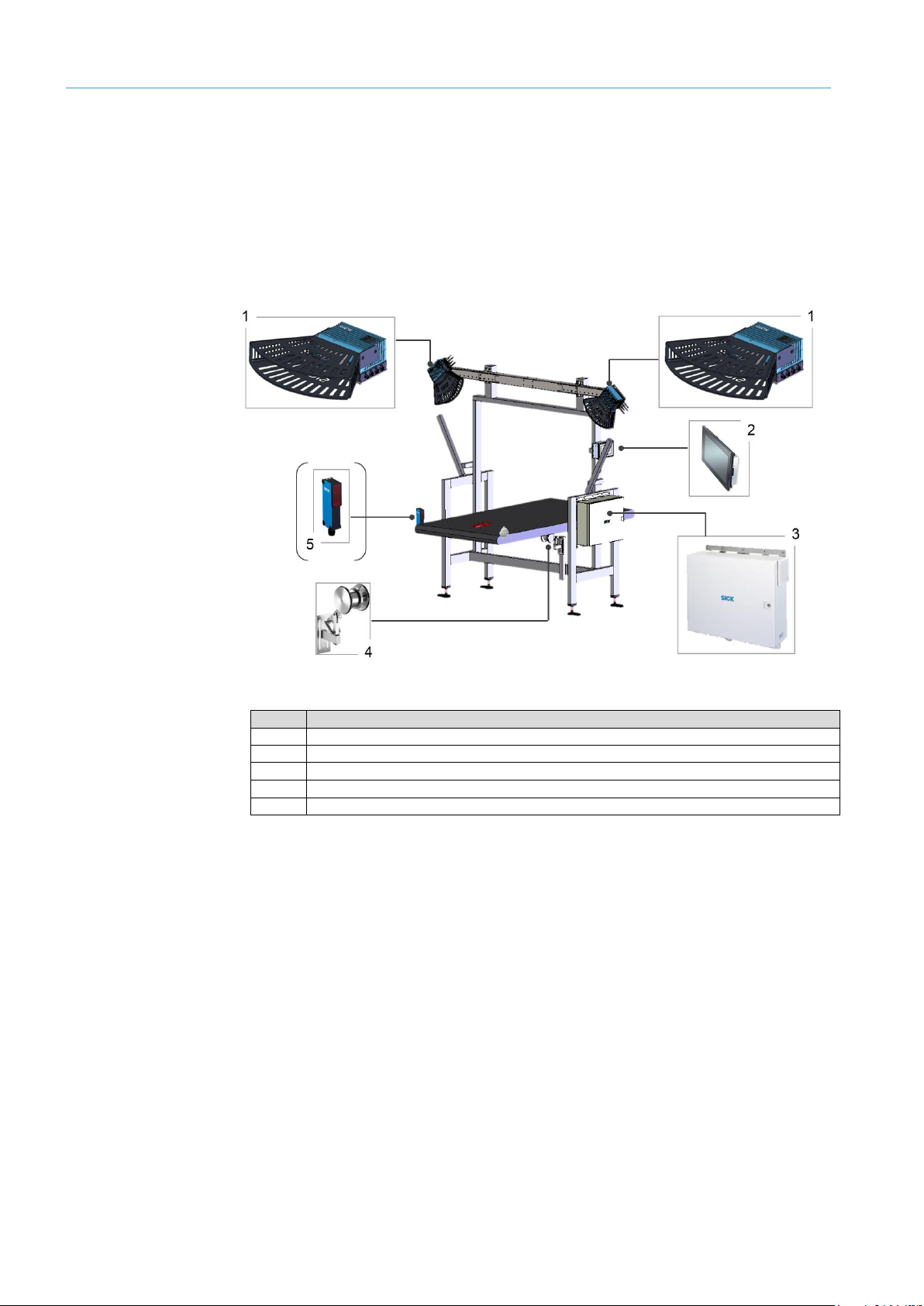
The VMS4200 / VMS5200 volume measurement system consists of two LMS4xxx volume
measurement devices, an LFT display, a measuring wheel encoder, and a cabinet
containing the SIM2000 control unit.
Systems for which measuring is triggered via a signal also have a photoelectric retro-
reflective sensor as an accessory.
Fig.3: System components
No.
Meaning
1
LMS4xxx volume measurement devices with laser protective cover
2
LFT display
3
Cabinet with SIM2000 control, voltage supply unit, and Ethernet switch
4
Measuring wheel encoder (e.g., DFV60)
5
Photoelectric retro-reflective sensor for triggered systems (e.g., WL-18-3)
All system components are mounted on a frame provided by the customer according to
the technical drawing. The volume measurement devices are mounted using a mounting
system included in the scope of delivery, which is attached to the frame.
Additional glare protection on the frame (beam blocker) prevents objects located outside
of the measuring range from being taken into account when calculating the measured
values.
The figures in these operating instructions show the mounting set consisting of a width-
adjustable telescopic tube with pre-mounted attachment mechanism for the volume
measurement devices and for mounting to a frame provided by the customer.
Note
Page 17
SYSTEM DESCRIPTION 3
17
8022965/2018-08-16|SICK
Subject to change without notice
O RI G IN A L O P ER A TI N G I NS T RU C TI O NS | VMS4200 / VMS5200 volume measurement system
The VMS4200 / VMS5200 volume measurement system consists of two LMS4xxx volume
measurement devices, which are mounted on the left and right above the conveying
equipment. The volume measurement devices configured as master and slave scan the
object and transmit the detected measuring points to the SIM2000 control unit.
Fig.4: Volume measurement devices
No.
Meaning
1
LMS4xxx master
2
LMS4xxx slave
3
Modular mounting set
The officially verifiable VMS5200 volume measurement system also has a separate LFT
display to show the measurement results, status information, the firmware version, and
the logbook (version history).
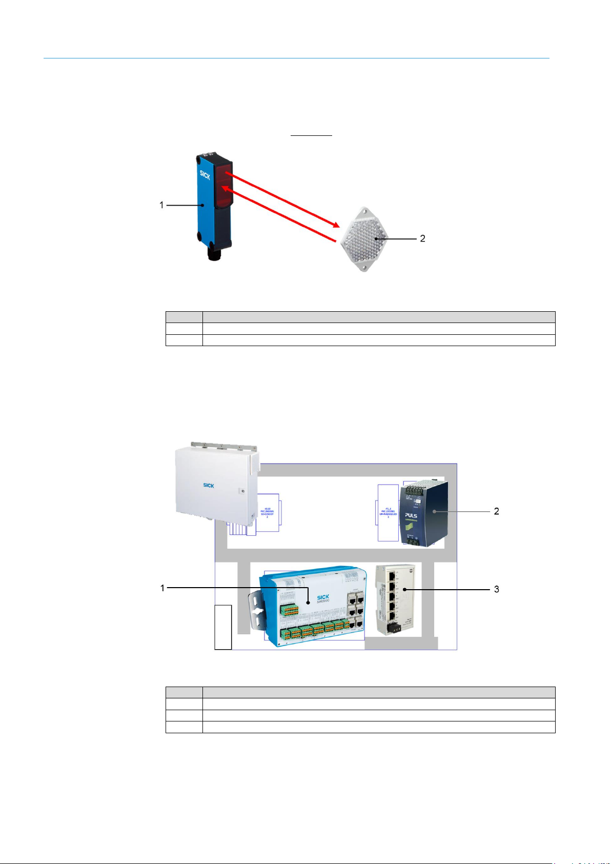
The measuring wheel encoder mounted below the conveyor belt is needed for position
determination of the object on the conveyor belt and for the calculation of the 3D model.
As part of this process, the encoder sends two incremental signals to the controller –
there is a 90-degree phase shift between the signals.
Measurement is performed directly on the running surface of the conveyor belt using a
precise measuring wheel, which is mounted on a spring-loaded arm.
Fig.5: Measuring wheel encoder (e.g., DFV60)
No.
Meaning
1
Running surface of the conveyor belt
2
Measuring wheel
3
Spring-loaded mounting arm
Volume measurement
devices
LFT display
Measuring wheel
encoder
Page 18
3 SYSTEM DESCRIPTION
18
8022965/2018-08-16|SICK
O RI G IN A L O P ER A TI N G I NS T RU C TI O NS | VMS4200 / VMS5200 volume measurement system
Subject to change without notice
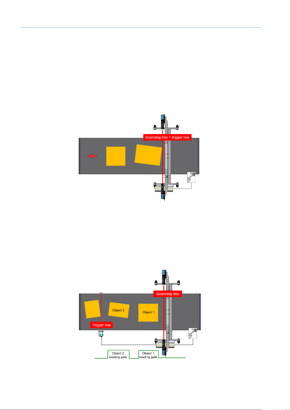
In the case of systems for which measuring is triggered, an additional photoelectric retro-
reflective sensor with reflector attached before the measuring field also provides a trigger
signal. The trigger signal activates the sensors and opens the internal reading gate. The
photoelectric sensor trigger is optionally available.
Fig.6: Photoelectric retro-reflective sensor with reflector (e.g., WL18-3)
No.
Meaning
1
Photoelectric retro-reflective sensor (e.g., WL18-3)
2
Reflector
The cabinet contains the SIM2000, which is the central control unit of the volume
measurement system, the voltage supply unit with fuse module for supplying voltage to
the components, and an Ethernet switch as the central interface for the sensor network.
In the case of the officially verifiable VMS5200, the SIM2000 also contains the legally
relevant memory (alibi memory) for the entire system.
Fig.7: SIC2000 cabinet
No.
Meaning
1
SIM2000 controller (for the VMS5200 with alibi memory)
2
Voltage supply unit with fuse modules
3
Ethernet switch
Photoelectric sensor
trigger
Cabinet
Page 19

SYSTEM DESCRIPTION 3
19
8022965/2018-08-16|SICK
Subject to change without notice
O RI G IN A L O P ER A TI N G I NS T RU C TI O NS | VMS4200 / VMS5200 volume measurement system
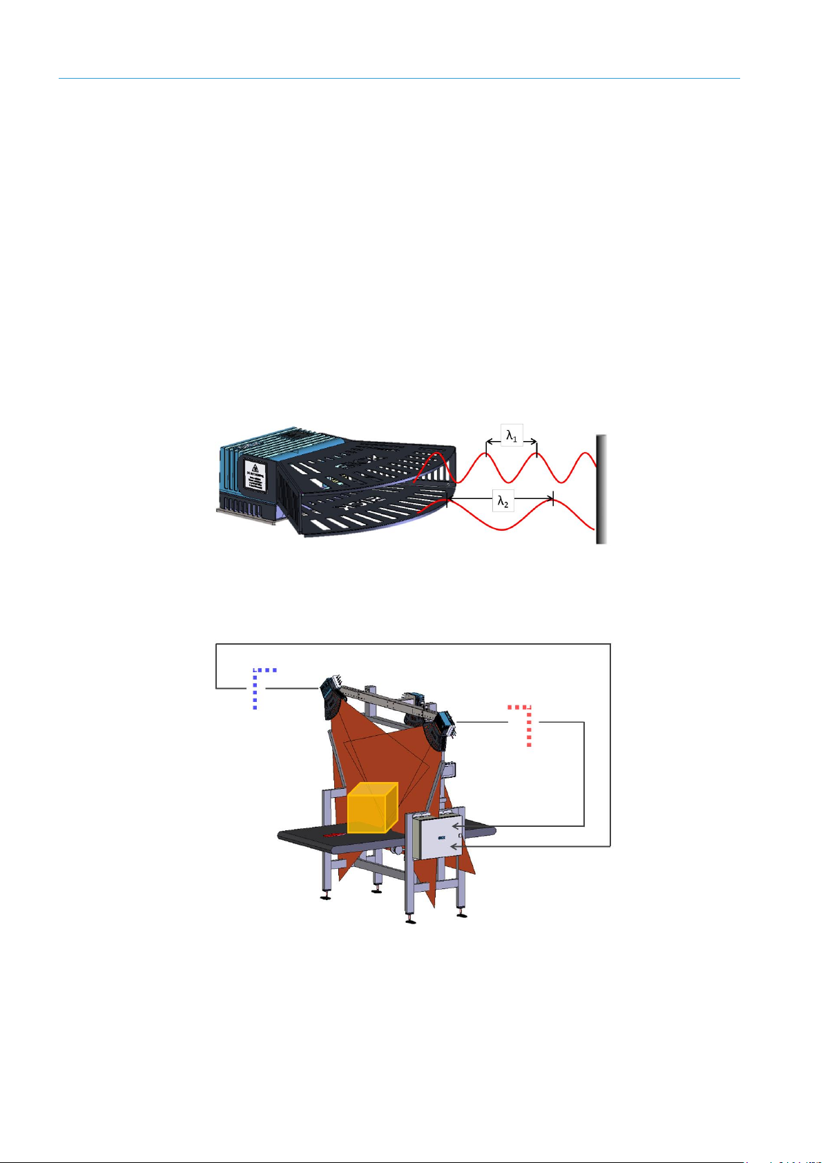
3.2.2 Expanding the system with a reading station
The VMS4200 / VMS5200 volume measurement system can be expanded to include a
reading station. The reading station allows automated identification of objects by reading
their bar codes, which in turn enables faster process automation. Depending on the
application case, this station can consist of scanners, cameras and/or a combination of
both in any desired arrangement.
The devices are connected to the volume measurement system via the CAN bus of the
SIM2000 controller. The controller links the acquired identification data with the
dimensional values calculated by the VMS4200 / VMS5200 and outputs both data types
to the higher-level system.
Fig.8: Expanding the system with a reading station
The volume measurement system can also supply the focus information for the connected
camera systems.
Note
Page 20
3 SYSTEM DESCRIPTION
20
8022965/2018-08-16|SICK
O RI G IN A L O P ER A TI N G I NS T RU C TI O NS | VMS4200 / VMS5200 volume measurement system
Subject to change without notice
3.3 Operating principle of the volume measurement system
The VMS4200 / VMS5200 volume measurement system measures cubic and irregularly
shaped objects that are moved past the measuring station on flat conveying systems.
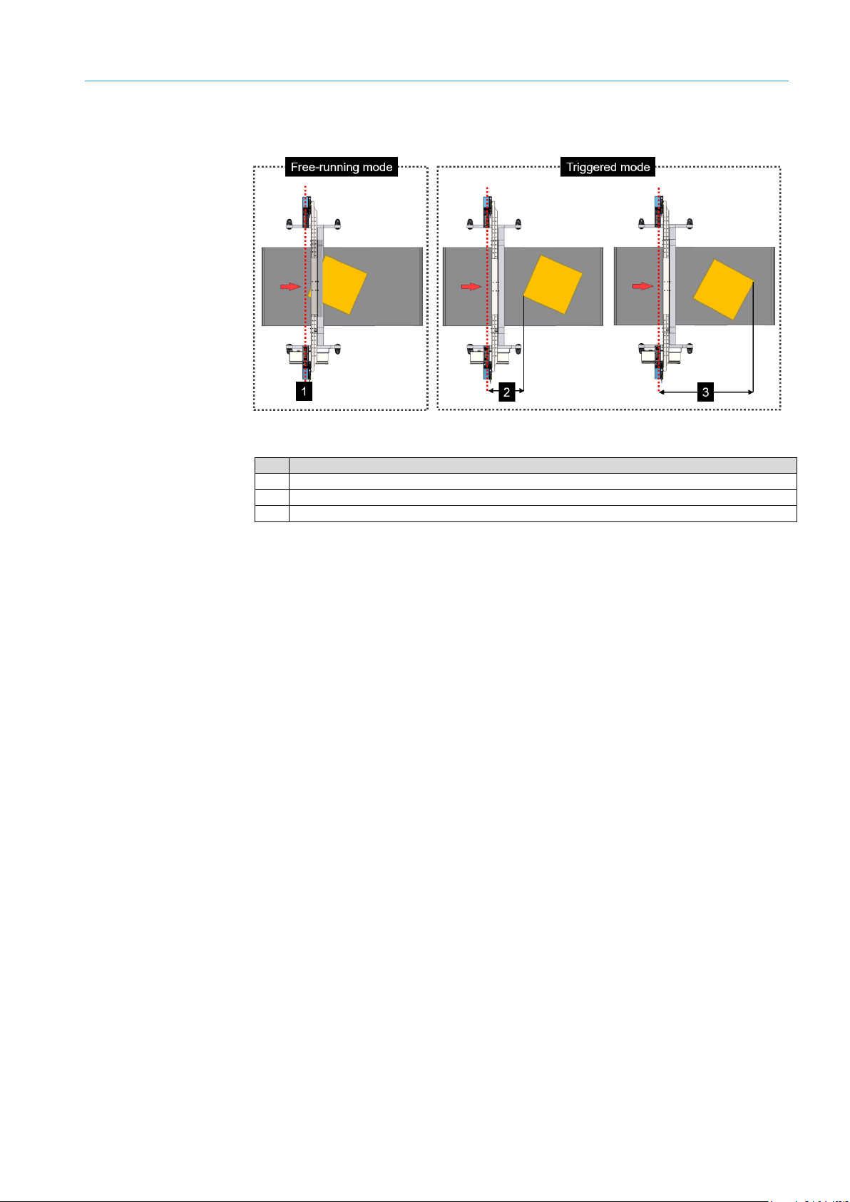
3.3.1 Operating modes
The volume measurement system can either be in free-running or triggered operating
mode.
In free-running mode, the volume measurement system detects the objects to be
measured itself. The measurement starts when an object enters the scanning line of the
volume measurement devices. It ends when the object leaves the scanning line.
Fig. 9: Free-running operating mode
In triggered mode, the object is detected via a trigger signal, not automatically. The trigger
signal can be triggered by the entry of the object into the path of a photoelectric retro-
reflective sensor or via a customer-controlled digital signal.
The trigger signal activates the volume measurement devices and opens the internal
reading gate. The reading gate determines the start and the end of the measuring
process. It corresponds to the trigger length in the conveying direction. The measuring
process lasts for as long as the reading gate is open, regardless of whether the object is
entering the scanning line or leaving it.
Fig. 10: Triggered operating mode
Object detection via a trigger signal also reliably detects very flat objects.
Free-running operating
mode
Triggered operating
mode
Note
Page 21
SYSTEM DESCRIPTION 3
21
8022965/2018-08-16|SICK
Subject to change without notice
O RI G IN A L O P ER A TI N G I NS T RU C TI O NS | VMS4200 / VMS5200 volume measurement system
In both operating modes, the incremental encoder supplies information to the conveying
equipment for exact position definition of the object. This information is required to
calculate the length information and for correct assignment of the measurement results
to the object.
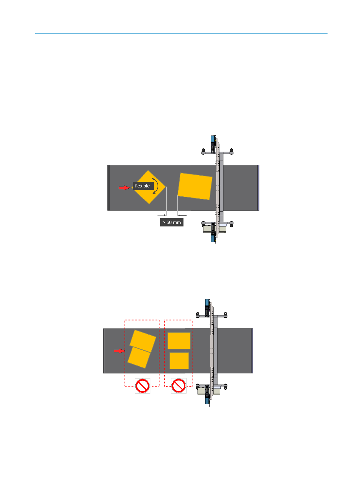
The supplying conveying equipment must pass on the objects to the volume
measurement system separately and at the minimum distance of 50 mm, which is
required for error-free processing. The objects may be placed on the conveyor belt in any
direction.
Fig. 11: Object conveyance with minimum distance and rotation angle
Objects that are touching or lying side-by-side cannot be measured using the volume
measurement system. The system does not give plausible measurement results in this
case.
Fig. 12: Unable to measure objects that are touching or lying side by side
Object tracking
Minimum distance
Page 22
3 SYSTEM DESCRIPTION
22
8022965/2018-08-16|SICK
O RI G IN A L O P ER A TI N G I NS T RU C TI O NS | VMS4200 / VMS5200 volume measurement system
Subject to change without notice
3.3.2 Calculating the volume
The calculation of measurement values begins as soon as an object is transported past
the volume measurement devices on the equipment below. The volume measurement
devices span a two-dimensional measuring range and scan the surfaces of the object
located within this range on the conveying equipment, without making contact. The
volume measurement device measures its surroundings in two-dimensional polar
coordinates, relative to its measurement origin. This is marked by a circular indentation
on the upper side of the housing.
The VMS4200 / VMA5200 is an active system featuring a laser in the visible range (red).
It does not require position marks, reflectors, or object illumination.
If a laser beam strikes an object, the position of that object is determined in terms of
distance and angle. This functions according to the principle of phase shift (continuous
wave). There is a phase difference between the transmitter and receiver beams resulting
from the run time of the light and the wavelength used. This phase difference is used to
calculate the distance of the object from the zero point.
Fig. 13: Functioning of the volume measurement device
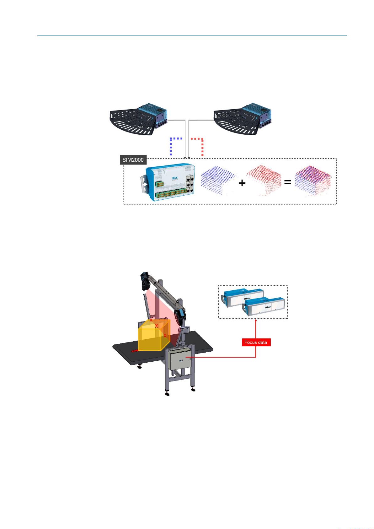
The measuring points determined by the two volume measurement devices are cyclically
transmitted to the SIM2000 controller.
Fig. 14: Measuring point determination by LMS4xxx
Page 23
SYSTEM DESCRIPTION 3
23
8022965/2018-08-16|SICK
Subject to change without notice
O RI G IN A L O P ER A TI N G I NS T RU C TI O NS | VMS4200 / VMS5200 volume measurement system
Using the established speed of the conveyor element and the specific position of the
object on the belt, the controller creates a spatial model from which the smallest
rectangular box that fully encloses the object is determined and the values for volume,
length, width and height are calculated. The measurement results of the officially verified
volume measurement system are shown on a separate LFT display.
Fig. 15: Volume calculation in the SIM2000
If the VMS4200 / VMS5200 volume measurement system is working in a complete
system with a reading station, the contour data can be used as the basis for the dynamic
camera focusing. For this purpose, the controller supplies continuous information about
the distance of the measurement sensor to the object surface via the CAN bus.
Fig. 16: Contour data as focus data for connected reading systems
Focus data
Page 24
3 SYSTEM DESCRIPTION
24
8022965/2018-08-16|SICK
O RI G IN A L O P ER A TI N G I NS T RU C TI O NS | VMS4200 / VMS5200 volume measurement system
Subject to change without notice
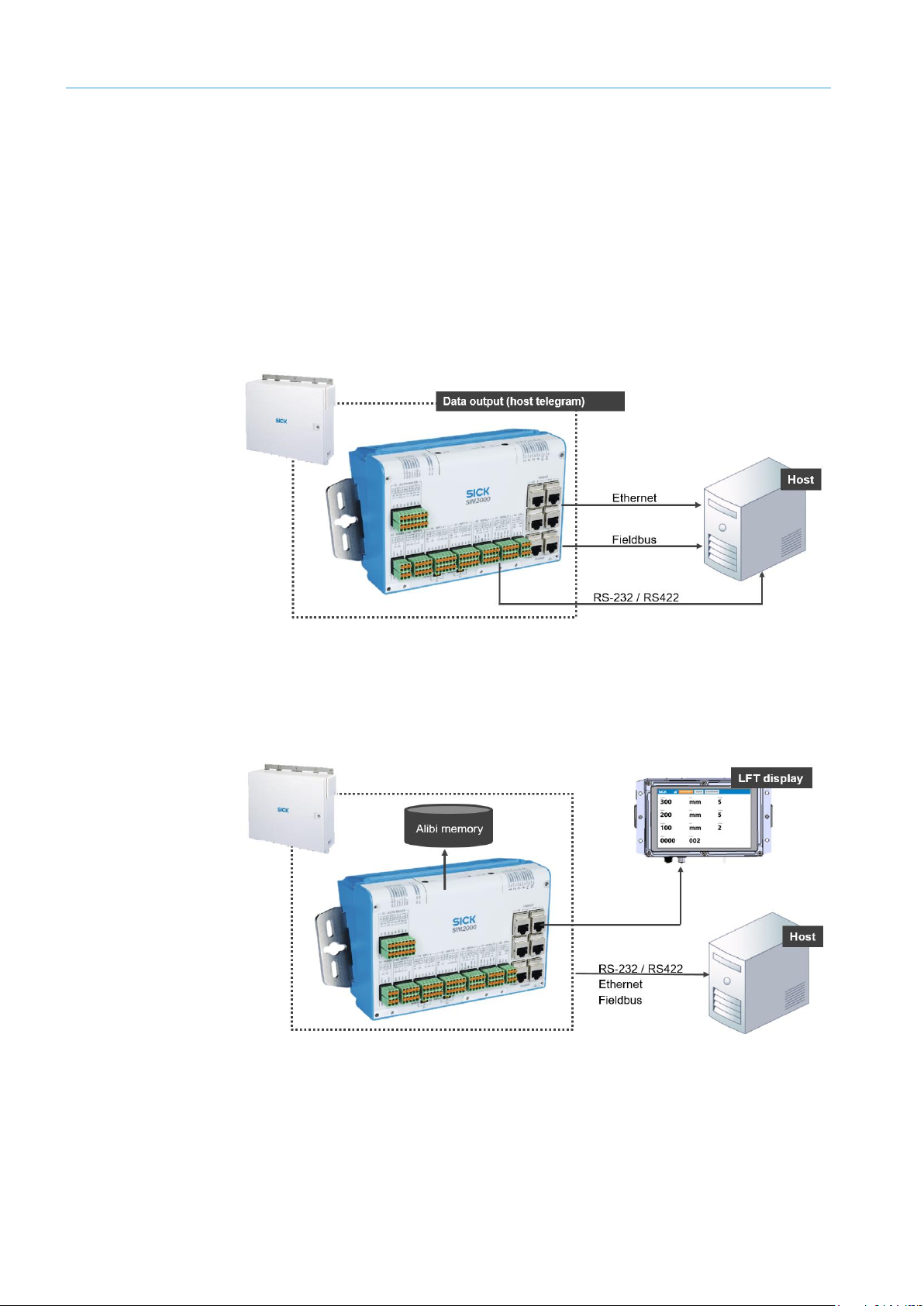
3.3.3 Data processing and data output
The SIM2000 is the volume measurement system’s central control unit. All the volume
measurement system information is processed here. It assumes the measuring points
from the volume measurement devices and uses this to generate a three-dimensional
model. It processes the signals from the measuring wheel encoder and (optionally from
the photoelectric retro-reflective sensor).
It calculates the volume and uses this to determine the length, width, and height. It
assigns the measurement results to the object and outputs them to the higher-level
system via a host telegram coordinated by the customer.
The calculated 3D point cloud of the calculated model can be optionally output here.
Fig. 17: Data output (host telegram)
In the case of an officially verifiable VMS5200, the measurement results are saved in the
SIM2000 alibi memory, which is required for verification, prior to output. The
measurement results are also displayed on the LFT display.
Fig. 18: Data processing (LFT mode)
VMS5200
Page 25
SYSTEM DESCRIPTION 3
25
8022965/2018-08-16|SICK
Subject to change without notice
O RI G IN A L O P ER A TI N G I NS T RU C TI O NS | VMS4200 / VMS5200 volume measurement system
You can define the output time via the SOPAS configuration software as follows.
Fig. 19: Configuring the time of the data output
No.
Meaning
1
Output as soon as possible after leaving the scanning line.
2
After a defined distance from X position in relation to the rear edge of an object.
3
After a defined distance from X position in relation to the leading edge of an object.
Configuring output
times
Page 26

3 SYSTEM DESCRIPTION
26
8022965/2018-08-16|SICK
O RI G IN A L O P ER A TI N G I NS T RU C TI O NS | VMS4200 / VMS5200 volume measurement system
Subject to change without notice
3.4 Nominal value conditions
The VMS4200 / VMS5200 volume measurement system can determine the length, width,
and height of the smallest rectangular box that fully encloses the object for cubic and
irregularly shaped measuring objects.
The different nominal operating conditions are described below depending on the object
size.
3.4.1 Fixed scale values
If the plant is operated without scale value switchover, the measuring range and scale
interval are fixed throughout the entire system depending on the application, and are
therefore the same for all measured objects.
Measuring range and scale interval for VMS5200 (operating condition 1)
Min.
Max.
Scale value (d)
Comment
Length
≥ 50 mm
≥ 2.0"
5,500 mm
216.0"
5 mm
0.2"
Longest dimension of
measuring object
Width
≥ 50 mm
≥ 2.0"
1,600 mm
63.0"
5 mm
0.2"
Dimension of measuring
object orthogonal to longest
dimension
Height
≥ 20 mm
≥ 1.0"
1,100 mm
< 43.0"
2 mm
0.1"
Maximum height of
measuring object relative to
belt surface
v
min
: ≥ 0.1 m/s
v
max
: 4.0 m/s, start/stop operation permitted.
Minimum distance between objects: 50 mm / 2"
Table 2: Measuring range and scale interval for VMS5200 (operating condition 1)
Measuring range and scale interval for VMS5200 (operating condition 2)
Min.
Max.
Scale value (d)
Comment
Length
≥ 50 mm
≥ 2.0"
5,500 mm
216.0"
5 mm
0.2"
Longest dimension of
measuring object
Width
≥ 50 mm
≥ 2.0"
1,600 mm
63.0"
5 mm
0.2"
Dimension of measuring
object orthogonal to longest
dimension
Height
≥ 50 mm
≥ 2.0"
1,100 mm
< 43.0"
5 mm
0.2"
Maximum height of
measuring object relative to
belt surface
v
min
: ≥ 0.1 m/s
v
max
: 4.0 m/s, start/stop operation permitted.
Minimum distance between objects: 50 mm / 2"
Table 3: Measuring range and scale interval for VMS5200 (operating condition 2)
Page 27

SYSTEM DESCRIPTION 3
27
8022965/2018-08-16|SICK
Subject to change without notice
O RI G IN A L O P ER A TI N G I NS T RU C TI O NS | VMS4200 / VMS5200 volume measurement system
Measuring range and scale interval for VMS5200 (operating condition 3)
Min.
Max.
Scale value (d)
Comment
Length
≥ 100 mm
≥ 4.0"
5,500 mm
216.0"
10 mm
0.4"
Longest dimension of
measuring object
Width
≥ 50 mm
≥ 2.0"
1,600 mm
63.0"
5 mm
0.2"
Dimension of measuring
object orthogonal to longest
dimension
Height
≥ 50 mm
≥ 2.0"
1,100 mm
< 43.0"
5 mm
0.2"
Maximum height of
measuring object relative to
belt surface
v
min
: ≥ 0.1 m/s
v
max
: 4.0 m/s, start/stop operation permitted.
Minimum distance between objects: 50 mm / 2"
Table 4: Measuring range and scale interval for VMS5200 (operating condition 3)
Measuring range and scale interval for VMS5200 (operating condition 4)
Min.
Max.
Scale value (d)
Comment
Length
≥ 100 mm
≥ 4.0"
5,500 mm
216.0"
10 mm
0.4"
Longest dimension of
measuring object
Width
≥ 100 mm
≥ 4.0"
1,600 mm
63.0"
10 mm
0.4"
Dimension of measuring
object orthogonal to longest
dimension
Height
≥ 50 mm
≥ 2.0"
1,100 mm
< 43.0"
5 mm
0.2"
Maximum height of
measuring object relative to
belt surface
v
min
: ≥ 0.1 m/s
v
max
: 4.0 m/s, start/stop operation permitted.
Minimum distance between objects: 50 mm / 2"
Table 5: Measuring range and scale interval for VMS5200 (operating condition 4)
Measuring range and scale interval for VMS5200 (operating condition 5)
Min.
Max.
Scale value (d)
Comment
Length
≥ 100 mm
≥ 4.0"
5,500 mm
216.0"
10 mm
0.4"
Longest dimension of
measuring object
Width
≥ 100 mm
≥ 4.0"
1,600 mm
63.0"
10 mm
0.4"
Dimension of measuring
object orthogonal to longest
dimension
Height
≥ 100 mm
≥ 4.0"
1,100 mm
43.0"
10 mm
0.4"
Maximum height of
measuring object relative to
belt surface
v
min
: ≥ 0.1 m/s
v
max
: 4.0 m/s, start/stop operation permitted.
Minimum distance between objects: 50 mm / 2"
Table 6: Measuring range and scale interval for VMS5200 (operating condition 5)
Page 28

3 SYSTEM DESCRIPTION
28
8022965/2018-08-16|SICK
O RI G IN A L O P ER A TI N G I NS T RU C TI O NS | VMS4200 / VMS5200 volume measurement system
Subject to change without notice
Measuring range and scale interval for VMS5200 (operating condition 6)
Min.
Max.
Scale value (d)
Comment
Length
≥ 100 mm
≥ 4.0"
5,500 mm
216.0"
10 mm
0.4"
Longest dimension of
measuring object
Width
≥ 50 mm
≥ 2.0"
1,600 mm
63.0"
5 mm
0.2"
Dimension of measuring
object orthogonal to longest
dimension
Height
≥ 20 mm
≥ 1.0"
1,100 mm
43.0"
2 mm
0.1"
Maximum height of
measuring object relative to
belt surface
v
min
: ≥ 0.1 m/s
v
max
: 4.0 m/s, start/stop operation permitted.
Minimum distance between objects: 50 mm / 2"
Table 7: Measuring range and scale interval for VMS5200 (operating condition 6)
Measuring range and scale interval for VMS5200 (operating condition 7)
Min.
Max.
Scale value (d)
Comment
Length
≥ 100 mm
≥ 4.0"
5,500 mm
216.0"
10 mm
0.4"
Longest dimension of
measuring object
Width
≥ 100 mm
≥ 4.0"
1,600 mm
63.0"
10 mm
0.4"
Dimension of measuring
object orthogonal to longest
dimension
Height
≥ 20 mm
≥ 1.0"
1,100 mm
43.0"
2 mm
0.1"
Maximum height of
measuring object relative to
belt surface
v
min
: ≥ 0.1 m/s
v
max
: 4.0 m/s, start/stop operation permitted.
Minimum distance between objects: 50 mm / 2"
Table 8: Measuring range and scale interval for VMS5200 (operating condition 7)
Measuring range and scale interval for VMS5200 (operating condition 8)
Min.
Max.
Scale value (d)
Comment
Length
≥ 200 mm
≥ 8.0"
5,500 mm
216.0"
20 mm
0.8"
Longest dimension of
measuring object
Width
≥ 50 mm
≥ 2.0"
1,600 mm
63.0"
5 mm
0.2"
Dimension of measuring
object orthogonal to longest
dimension
Height
≥ 20 mm
≥ 1.0"
1,100 mm
43.0"
2 mm
0.1"
Maximum height of
measuring object relative to
belt surface
v
min
: ≥ 0.1 m/s
v
max
: 4.0 m/s, start/stop operation permitted.
Minimum distance between objects: 50 mm / 2"
Table 9: Measuring range and scale interval for VMS5200 (operating condition 8)
Page 29
SYSTEM DESCRIPTION 3
29
8022965/2018-08-16|SICK
Subject to change without notice
O RI G IN A L O P ER A TI N G I NS T RU C TI O NS | VMS4200 / VMS5200 volume measurement system
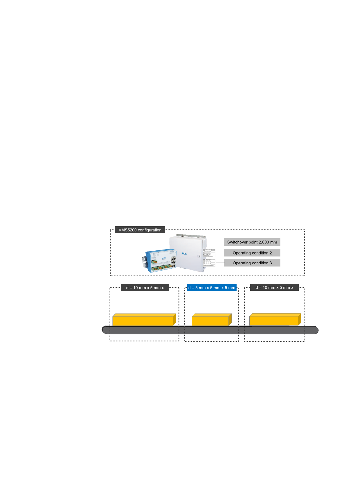
3.4.2 Dynamic scale value switchover
In the case of dynamic scale value switchover, the scale interval can be changed depending
on the relevant measured object dimension, i.e., length, width, or height.
The defined scale intervals need to be documented on the information label. It is only
permitted to select scale intervals based on the scale values from section 3.4.1 Fixed scale
values.
The measurement accuracy switchover can take place from object to object. The switchover
point is set during commissioning and cannot be changed when the calibration switch is
activated and locked (for information on the calibration switch, see chapter 3.6.3 SD card
with alibi memory).
In the following example, the volume measurement system is working with the two scale
intervals 5 mm x 5 mm x 5 mm (scale values for operating condition 2) and 10 mm x
5 mm x 5 mm (scale values for operating condition 3). An object length of 2,000 mm has
been defined as the switchover point during commissioning.
Objects with a length less than or equal to 2,000 mm are measured under operating
condition 2 with the scale values 5 mm x 5 mm x 5 mm.
For objects with a length greater than 2,000 mm, the volume measurement system
automatically uses the scale values 10 mm x 5 mm x 5 mm due to the detected object
length.
Fig. 20: Dynamic scale value switchover
In the case of dynamic scale value switchover, the relevant scale values (see the tables
above) used by the VMS5200 are also displayed on the LFT display together with the
measurement result.
Example
Note
Page 30

3 SYSTEM DESCRIPTION
30
8022965/2018-08-16|SICK
O RI G IN A L O P ER A TI N G I NS T RU C TI O NS | VMS4200 / VMS5200 volume measurement system
Subject to change without notice
3.5 System requirements
3.5.1 Required interfaces
The following is required to operate the VMS5200 volume measurement system:
Supply voltage AC 100 ... 264 V / 50 ... 60 Hz for the VMS5200 components.
Host computer with RS-232, RS-422/485, Ethernet or PROFIBUS data interface for
further processing of the measurement results.
3.5.2 Requirements at the operation site
The operation site of the volume measurement system must have the following features:
Enclosed or covered spaces
Flat and firm surface
Low-vibration environment
Protected from wind and free of drafts
No direct sunlight
Well-lit
Clean and dry (air humidity 95%, non-condensing)
Room temperature from –10 °C to 50 °C
Regardless of the space requirements for the components, there must be enough space
at the operation site for the following activities:
Reading the measurement results off the LFT display
Opening the cabinet door completely
Cleaning, repair, and service
3.5.3 Object requirements
The transported objects must have the following properties:
Cubic and irregularly shaped objects can be measured.
All measuring objects must be dimensionally stable and have non-reflective and
opaque surfaces.
3.5.4 Conveying equipment requirements
The VMS4200 / VMS5200 volume measurement system is designed for flat conveying
systems.
The conveyor speed must not exceed 4 m/s.
Relative movements of the measuring objects are not permitted while measurements are
in progress. The measuring objects must not be exposed to any vibrations.
Page 31

SYSTEM DESCRIPTION 3
31
8022965/2018-08-16|SICK
Subject to change without notice
O RI G IN A L O P ER A TI N G I NS T RU C TI O NS | VMS4200 / VMS5200 volume measurement system
NOTE
Transport behavior of the packages
Any relative movement of the package to the conveyor belt will cause the measurement
results to be distorted.
Objects that rotate, vibrate, roll, or slip on the belt and uneven conveying surfaces may
reduce the accuracy.
General requirements
In an area before and after the measuring station, the conveying equipment must run
straight and evenly, and may not exhibit any deviation. Both the front and back area in
this case correspond to the maximum length of the measuring objects (see also
chapter 3.4 Nominal value conditions). If the specific installation position of the
measuring equipment does not meet this requirement, the maximum length of the
measuring objects must be restricted accordingly and is to be specified on the
information label (see chapter 3.6.1).
Positive or negative slopes of the conveying equipment must be kept flat enough to
prevent the measuring objects from sliding.
The conveying equipment must not have any shiny or reflective surfaces.
No guides for measuring objects may be installed in the vicinity of the measuring
station.
3.5.5 Mounting requirements
The measurement system requires both a stable, secure frame to prevent rotation and a
sufficient load bearing capacity to support the system components.
To achieve a high level of measurement accuracy, use the optional aluminum profiles
and the corresponding mounting kits for mounting.
The frame must be attached to the conveying system in such a way that it is free of
vibrations and oscillations.
The frame must be positioned at right angles to the conveying direction.
The maximum working range of the LMS4xxx is 3 m. The minimum distance between the
zero point of the LMS4xxx measurement and the measuring object is 700 mm. In the
delivery state, the zero point of the distance measurement is the origin of the laser
(marked with a point on the upper and lower side of the housing).
The working range of the LMS4xxx covers an angle of 70°.
Frame
Mounting the
LMX4xxx
Page 32

3 SYSTEM DESCRIPTION
32
8022965/2018-08-16|SICK
O RI G IN A L O P ER A TI N G I NS T RU C TI O NS | VMS4200 / VMS5200 volume measurement system
Subject to change without notice
Fig. 21: Working range of the LMS4xxx
The volume measurement devices are mounted on the right and left of the conveying
equipment in such a way that it is free of vibrations and oscillations.
To achieve a high level of measurement accuracy, use the supplied mounting set with
telescopic tube and brackets when mounting the equipment. See also chapter 4.1
Mounting volume measurement devices.
The telescopic tube must be mounted precisely at right angles to the conveying
equipment.
To achieve an optimal read result, observe the following:
The smallest permissible distance of the measuring object from the zero point of the
LMS4xxx is 700 mm. The zero point is marked on both the upper and lower side of the
housing of the LMS4xxx.
Fig. 22: Requirements for mounting the LMS4xxx
The typical space requirement for the installation of the volume measurement system
is approximately 700 mm above the tallest object.
The volume measurement devices must have a clear view of the conveying system.
The laser beams of the LMS4xxx should not reach beyond the application space, so
that people or goods, which are being transported on an adjacent conveyor system, are
not detected. The boundary is set via beam separation (see below).
The maximum detection must be limited to the working range of three meters, as the
specified scale interval may otherwise not be achieved.
The LMS4xxx must be far enough away from bends, induction lines, start/stop areas,
areas with upward and downward slopes, and breaks in the conveying system.
Recommendation
Optimization
Page 33

SYSTEM DESCRIPTION 3
33
8022965/2018-08-16|SICK
Subject to change without notice
O RI G IN A L O P ER A TI N G I NS T RU C TI O NS | VMS4200 / VMS5200 volume measurement system
It is important to make sure that the volume measurement devices are aimed at the
beam blockers. The beam blockers attached to the mounting frame prevent objects
located outside of the measuring range from being taken into account when calculating
the measured values, therefore also preventing the falsification of the measurement
result.
The beam blockers of the lower volume measurement devices also enable detection of
objects with excessively low remission (black objects).
Fig. 23: Beam blockers for restricting the laser beams to the measuring range
Beam separation
Page 34

3 SYSTEM DESCRIPTION
34
8022965/2018-08-16|SICK
O RI G IN A L O P ER A TI N G I NS T RU C TI O NS | VMS4200 / VMS5200 volume measurement system
Subject to change without notice
3.6 Officially verifiable operation
The MID-compliant, and therefore officially verifiable, VMS5200 system has been typetested by the Physikalisch-Technische Bundesanstalt (PTB). It can therefore be used for
billing purposes.
When operating the VMS5200 in a situation requiring official legal-for-trade verification,
be sure to comply with applicable national law. SICK can assist you with this in an
advisory capacity on request. However, this assistance is not a substitute for legal advice.
3.6.1 Information labels
There are two types of information labels:
To ensure that the VMS5200 volume measurement system is operated in such a way
that it can be verified as legal for trade, one or two system information labels –
depending on whether fixed scale values or dynamic scale value switchover is in
operation – containing information about the maximum and minimum dimensions for
the length (L), width (W), and height (H), as well as the relevant scale value (d) must be
attached to the volume measurement system in a highly visible location.
The missing values are to be entered by hand on site, using waterproof permanent ink.
Each system information label must be attached to the system in such a manner that it
can be seen by the operator and assigned to the volume measurement system.
The type labels of the LMS4xxx volume measurement devices contain additional
information and are to be affixed to the information label in the LMS 1 and LMS 2
fields. The SW field contains the version number of the device software.
The label with the metrology information label must also be attached.
The SIM2000 system controller type label is affixed to the metrology information label.
Page 35

SYSTEM DESCRIPTION 3
35
8022965/2018-08-16|SICK
Subject to change without notice
O RI G IN A L O P ER A TI N G I NS T RU C TI O NS | VMS4200 / VMS5200 volume measurement system
System information label with fixed scale values
If fixed scale values are defined for the VSM5200, the relevant operating condition is
specified on the information label in indelible ink.
The fix scale value and the measuring unit (mm or inch) must be specified on the
namepalte in indelible ink.
The LMS4xxx type labels must be affixed in the appropriate fields.
Fig. 24: Nameplate for the VMS5200 for fixed scale values with affixed type labels for the
LMS4xxx
Page 36

3 SYSTEM DESCRIPTION
36
8022965/2018-08-16|SICK
O RI G IN A L O P ER A TI N G I NS T RU C TI O NS | VMS4200 / VMS5200 volume measurement system
Subject to change without notice
System information labels with dynamic scale value switchover
In the case of dynamic scale value switchover, the scale values of the two scale intervals
used must be described in two separate information labels and attached to the system
indelibly.
The dynamic scale value and the measuring unit (mm or inch) must be specified on the
information label for scale interval 1 in indelible ink. The type labels for the LMS4xxx are
also affixed to this nameplates.
The dynamic scale value with the associated dimension values must be specified on the
nameplates for scale interval 2.
Fig. 25: MID Nameplates for the VMS5200 (dynamic scale value switchover) with affixed type
labels for the LMS4xxx
Page 37

SYSTEM DESCRIPTION 3
37
8022965/2018-08-16|SICK
Subject to change without notice
O RI G IN A L O P ER A TI N G I NS T RU C TI O NS | VMS4200 / VMS5200 volume measurement system
Metrology information label
The metrology marking – M18 for the year 2018 in the figure below – must be indicated
in accordance with Article 21 of the MID. Additionally, the CE marking and the number of
the notified body – 0102 for PTB in the figure below – must be indicated.
The SIM2000 system controller type label is affixed to the metrology information label.
Fig. 26: Sample label for the metrology marking, CE marking, and number of the notified body
with SIM2000 type label
The nature of the metrology information label must be such that its removal will result in
the destruction of the label itself or of a security seal.
Note
Page 38

3 SYSTEM DESCRIPTION
38
8022965/2018-08-16|SICK
O RI G IN A L O P ER A TI N G I NS T RU C TI O NS | VMS4200 / VMS5200 volume measurement system
Subject to change without notice
3.6.2 Security seal
In order to protect measurement systems that have been verified as legal for trade
against manipulation, all legally relevant components that influence the measurement
result must be provided with seals in accordance with the seal diagram depicted in the
figure below.
The security seals are attached to the VMS5200 components after mounting and the
conformity check.
NOTE
Never tamper with the seal
The seals must not be broken.
If a seal is broken, the verification validity period will end prematurely, and the VMS5200
must no longer be used for billing purposes. This must be reported to the manufacturer
and the office of weights and measures.
Security seals prevent the attachment mechanism of the volume measurement devices
and the plug connectors of the connections from misaligning.
Fig. 27: Security seals for the VMS5200 volume measurement devices
No.
Meaning
1
Security seal on the mounting plate of the modular bracket on the frame.
2
Security seal on the two adjusters of the telescopic tube.
3
Security seal on the retaining plates of the volume measurement devices.
4
Security seal on all plug connectors for the electrical connections.
Seal on the
VMS5200
Page 39

SYSTEM DESCRIPTION 3
39
8022965/2018-08-16|SICK
Subject to change without notice
O RI G IN A L O P ER A TI N G I NS T RU C TI O NS | VMS4200 / VMS5200 volume measurement system
A manipulation protective plate protects the SIM2000 controller installed in the cabinet
against disassembly and removal of the connections. The protective plate also prevents
the DIP switch from shifting.
The service flap on the upper side of the controller is also sealed to prevent the microSD
memory card containing the alibi memory from being removed.
Fig. 28: SIM2000 security seals
No.
Meaning
1
Manipulation protective plate.
2
Security seal on the manipulation plate.
3
Security seal on the service flap.
4
Data lines protected against removal.
5
Cable entries protected against removal.
A manipulation protective plate protects the Ethernet switch installed in the cabinet
against disassembly and removal of the connecting cables.
Fig. 29: Ethernet switch security seals
No.
Meaning
1
Manipulation protective plate.
2
Security seal on the manipulation plate.
Security seal
on the SIM2000
Security seal on the
Ethernet switch
Page 40

3 SYSTEM DESCRIPTION
40
8022965/2018-08-16|SICK
O RI G IN A L O P ER A TI N G I NS T RU C TI O NS | VMS4200 / VMS5200 volume measurement system
Subject to change without notice
The measuring wheel encoder is protected against disassembly and disconnection of the
connecting cable.
Fig. 30: Security seals on the measuring wheel encoder (DFV60 in the image)
No.
Meaning
1
Security seal on the bracket.
2
Security seal on the male connector.
The LFT display is protected against disassembly and disconnection of the connecting
cable.
Fig. 31: Security seals on the LFT display
No.
Meaning
1
Security seal on the LFT display housing.
2
Security seal on the male connectors.
Security seal on the
Ethernet switch
Security seal on the LFT
display
Page 41

SYSTEM DESCRIPTION 3
41
8022965/2018-08-16|SICK
Subject to change without notice
O RI G IN A L O P ER A TI N G I NS T RU C TI O NS | VMS4200 / VMS5200 volume measurement system
3.6.3 SD card with alibi memory
The slot for the microSD card containing the alibi memory is located beneath the sealed
service flap on the upper side of the device. A second SD card containing the firmware is
included with delivery.
Fig. 32: MicroSD card with alibi memory and firmware
Alibi memory
Measurement and calibration legislation stipulates that a measured value which is
detected on a measurement device that has been verified as legal for trade in an
application requiring official verification, and is transmitted to an electronic data
processing system must be available to read from the alibi memory for at least three
months before it can be overwritten with new data sets.
Documentation takes place in what is referred to as an alibi memory, which is a fixed
component of the officially verifiable system. This memory must be approved by the
Physikalisch-Technische Bundesanstalt (PTB) or another notified body.
The VMS5200 volume measurement system uses the alibi memory to ensure compliance
with official verification regulations for measurement data, and to provide traceability for
all measurement processes within the measurement system. For this purpose, the alibi
memory stores all measured values recorded along with their date, time, and a unique
consecutive alibi ID.
NOTE
The operating entity of the VMS5200 system variant is responsible for complying with
the relevant regulations and guidelines at all times in connection with operating the
system in a way that is verified as legal for trade.
Page 42

3 SYSTEM DESCRIPTION
42
8022965/2018-08-16|SICK
O RI G IN A L O P ER A TI N G I NS T RU C TI O NS | VMS4200 / VMS5200 volume measurement system
Subject to change without notice
Separation of application software and metrological software
The firmware of the volume measurement system is separated into an application part
and a metrologically relevant part.
This separation allows customer-specific parameters to be changed via the SOPAS
configuration software without violating the LFT conformity of the volume measurement
system.
The software relevant to the LFT conformity with the associated LFT parameters is
protected by a calibration switch. This calibration switch is also located beneath the
sealed service flap.
It is interlocked by turning the calibration switch to the zero position.
Fig. 33: Calibration switch for interlocking the metrological software parameters
Page 43

SYSTEM DESCRIPTION 3
43
8022965/2018-08-16|SICK
Subject to change without notice
O RI G IN A L O P ER A TI N G I NS T RU C TI O NS | VMS4200 / VMS5200 volume measurement system
3.6.4 LFT display
When operating the VMS5200 volume measurement system in a way that is verified as
legal for trade, the measurement results are displayed one after another on an LFT
display connected to the controller.
The LFT display also allows users to display system information, the current firmware
version, and a version history.
Fig. 34: User interface of the LFT display
The screen is controlled by gently touching the respective touch pads. The touch pads on
the LFT display vary according to the operational context.
NOTE
Notes on the correct use of the LFT display
You are only permitted to touch the LFT display with your fingers. Gently press the touch
pads to operate them. Do not apply force.
Do not operate the LFT display with pointed or sharp objects; otherwise, the surface of the
LFT display will become damaged.
NOTE
The operation of the LFT display only permits the display of measurement data and
system information.
No measurement and system data can be changed.
Page 44

3 SYSTEM DESCRIPTION
44
8022965/2018-08-16|SICK
O RI G IN A L O P ER A TI N G I NS T RU C TI O NS | VMS4200 / VMS5200 volume measurement system
Subject to change without notice
Displaying the measurement results
The MEASUREMENT tab displays the results of the last measurement. The length, width,
and height are output with scale values in mm.
The status line provides additional information about the measurement result and
indicates, for example, whether the measurement was completed successfully (display
reads 0 0 0 0). Other numerical sequences indicate the reason why a measurement was
invalid.
Fig. 35: LFT display – display of the measurement results
Displaying the firmware version
The VERSION tab displays the current firmware statuses of the system components with
the firmware checksums saved in the SIM2000. The checksum of the metrologically
relevant LFT test parameters saved in the SIM2000 is also listed.
Fig. 36: LFT display – display of the firmware versions
Page 45

SYSTEM DESCRIPTION 3
45
8022965/2018-08-16|SICK
Subject to change without notice
O RI G IN A L O P ER A TI N G I NS T RU C TI O NS | VMS4200 / VMS5200 volume measurement system
The HISTORY buttons can be used to call up current and any older version statuses of a
component.
Fig. 37: LFT display – display of the firmware versions (history)
Displaying the data sets saved in the alibi memory
The ALIBI BROWSER tab displays the data sets saved in the alibi memory. Enter a date to
specify the date from which the data sets should be displayed.
The display is automatically updated.
Fig. 38: LFT display – display of the data sets saved in the alibi memory
Page 46

3 SYSTEM DESCRIPTION
46
8022965/2018-08-16|SICK
O RI G IN A L O P ER A TI N G I NS T RU C TI O NS | VMS4200 / VMS5200 volume measurement system
Subject to change without notice
3.6.5 Test instructions for market surveillance
This chapter describes the procedure for inspecting the certified VMS5200 measurement
system with regard to:
The performance of metrological measurements with defined test objects and the
display of the measurement results on the LFT display.
The display of data sets stored in the alibi memory on the LFT display.
The display of system component firmware versions via the LFT display.
Starting the system
▸
Establish the voltage supply of the devices via the voltage supply unit in the SIC2000.
All system components start up automatically and are then ready for use.
The LFT display shows the MEASUREMENT tab. No measured values are available yet.
Measuring test objects
▸
Measure test objects made from a dimensionally stable material of various shapes and
surface qualities.
▸
The measurements can be performed in both free-running and triggered mode (for
more information on this, see also chapter 3.3.1 Operating modes).
The nominal dimensions (length, width, height) must cover approximately 90%, 50%,
and 10% of the total measuring range for each dimension.
The actual dimensions must not be less than the minimum dimensions or exceed
the maximum dimensions specified for the VMS4200 / VMS5200.
▸
Ensure that the required minimum distance of 50 mm is maintained between the test
objects.
▸
Compare the dimension values displayed on the LFT display with the actual values of
the respective measured test object.
Valid measurement results have the status 0 0 0 0. They are LFT-verified and can be used
for billing.
Note
Note
Page 47

SYSTEM DESCRIPTION 3
47
8022965/2018-08-16|SICK
Subject to change without notice
O RI G IN A L O P ER A TI N G I NS T RU C TI O NS | VMS4200 / VMS5200 volume measurement system
Displaying values saved in the alibi memory
The measured values saved in the alibi memory of the VMS5200 can be displayed on the
display.
▸
Switch to the ALIBI BROWSER tab in the LFT display. The data sets saved in the alibi
memory are listed line by line. A maximum of 20 data sets can be displayed on one
page.
Valid measurement results have the status 0 0 0 0. They are LFT-verified and can be
used for billing.
▸
Use the arrow buttons to change between the individual pages. The numbers between
the arrow keys indicate which page you are on and how many pages there are in total.
Symbol
Meaning
Opens the first page.
Changes from the current page to the previous page.
Changes from the current page to the next page.
Opens the last page.
▸
Enter a date to set the period for which you want to display the alibi memory values.
This list is updated automatically.
Page 48

3 SYSTEM DESCRIPTION
48
8022965/2018-08-16|SICK
O RI G IN A L O P ER A TI N G I NS T RU C TI O NS | VMS4200 / VMS5200 volume measurement system
Subject to change without notice
Displaying firmware versions
▸
Switch to the VERSION tab in the LFT display.
The current firmware statuses of the system components are displayed together with
the checksum saved in the SIM2000.
▸
Press the HISTORY button to call up current and any older version statuses of a
component.
Page 49

SYSTEM DESCRIPTION 3
49
8022965/2018-08-16|SICK
Subject to change without notice
O RI G IN A L O P ER A TI N G I NS T RU C TI O NS | VMS4200 / VMS5200 volume measurement system
Displaying the history of the checksum for LFT parameters
▸
In the VERSION tab, read off the checksum of the metrologically relevant LFT
parameters saved in the SIM2000.
▸
On the right next to the SIM2000 parameter checksum, press the HISTORY button to
call up current and any older checksums for the LFT parameters. Modified SIM2000
LFT parameters must be officially reported to the responsible verification authority in
each case.
Page 50

3 SYSTEM DESCRIPTION
50
8022965/2018-08-16|SICK
O RI G IN A L O P ER A TI N G I NS T RU C TI O NS | VMS4200 / VMS5200 volume measurement system
Subject to change without notice
3.7 Status indicators
3.7.1 LMS4xxx volume measurement devices
Four LEDs provide a visual indication of the operational status of the device and any
occurring faults.
Fig. 39: Status indicators of the LMS4xxx
LED
Color
Meaning
Status
Green
Device ready.
Yellow
Warning.
Red
Hardware or software error.
Ethernet
Green
LINK route established (LED continuously lit).
Data transmission (LED flashing).
Sync
Green
Master: Sync signals are being sent (LED continuously lit).
Slave: Sync connection active (flashing), sync connection active and
device synchronized (LED continuously lit).
In/Out
Yellow
Switching input or switching output active.
Table 10: Status indicators of the LMS4xxx
3.7.2 Status indicators on the SIM2000 controller
During operation, the operational statuses of the controller connections are indicated
visually by status LEDs.
Using these status indicators, you can find out quickly and easily whether the cabinet and
the peripherals are working properly or whether any faults or errors have occurred.
Fig. 40: Status indicators – LEDs on the controller
For more information, please see the operating instructions for the SIC2000.
Chapter 8.4.2 Checking the incremental encoder describes how to check the
functionality of the connected measuring wheel encoder and the photoelectric retro-
reflective sensor.
Page 51

SYSTEM DESCRIPTION 3
51
8022965/2018-08-16|SICK
Subject to change without notice
O RI G IN A L O P ER A TI N G I NS T RU C TI O NS | VMS4200 / VMS5200 volume measurement system
3.8 Interfaces
Numerous interfaces are available on the controller of the cabinet.
Fig. 41: Data interfaces
No.
Interface
Connection
Function
1
IO-Link
IO LINK
MASTER
IO-Link to support the point-to-point communication with
sensors without any effort required for addressing.
The interfaces can also be used as digital inputs and
outputs.
2
Ethernet
ETHERNET
4 Ethernet interfaces to provide the measuring and reading
results in defined output formats for further processing by
the host computer, to connect sensors, and to connect to a
network or a configuration PC.
3
Fieldbus
FIELDBUS
2 Ethernet-based fieldbus interfaces to provide the
measuring and reading results in defined output formats
for further processing by the host computer.
4
CAN bus
CAN
Support for a SICK CAN network to integrate the connected
sensors.
5
Serial host
interfaces
SERIAL A,
SERIAL B
4 serial interfaces supported by
RS-232 / RS-422 to provide the measuring and reading
results in defined output formats for further processing by
the host computer. Read diagnosis and monitoring of the
host interfaces.
6
Digital I/Os
INPUT
Various items, including the sensors for triggering and the
encoder signal, are connected to eight digital (isolated)
inputs.
Additional digital inputs can be configured via the IO-Link
interface. These are not isolated.
7
Digital I/Os
OUTPUT
Switching signals which are independent of one another
can be output at four digital (isolated) outputs.
The status of a measuring and reading result (e.g., a failed
decoding) can be displayed in this way. In addition, it is
possible to signal system statuses (operational readiness,
excess temperature in the cabinet, etc.).
Additional digital outputs can be configured via the IO-Link
interface. These are not isolated.
Table 11: Function of data interfaces
Page 52

4 MOUNTING
52
8022965/2018-08-16|SICK
O RI G IN A L O P ER A TI N G I NS T RU C TI O NS | VMS4200 / VMS5200 volume measurement system
Subject to change without notice
4 Mounting
4.1 Mounting volume measurement devices
The volume measurement devices are mounted above the conveying equipment using the
mounting set included in the scope of delivery.
The mounting set has a modular design and is preconfigured accordingly upon delivery. It
consists of a width-adjustable telescopic tube with pre-mounted and pre-aligned mounting
plates to hold the volume measurement devices.
The telescopic tube is attached to the customer’s frame via a pre-mounted attachment
mechanism, consisting of a mounting plate and a spring plate.
Fig. 42: Mounting the volume measurement devices
No.
Meaning
1
Telescopic rod with adjuster via defined wells
2
Components of the attachment mechanism for mounting the modular bracket on the
frame
Mounting plate
Spring plate
3
Retaining plates for mounting the LMSxxx volume measurement devices.
Steps for mounting
1. Assemble the profiles of the telescopic tube.
2. Mount the telescopic rod on the frame.
3. Mount the volume measurement device on the retaining plates.
Adjustment after mounting is not required. The volume measurement devices are
correctly pre-aligned at the factory by aligning the retaining plates on the telescopic rod.
If you are using an alternative attachment mechanism (e.g., mounting the volume
measurement devices on a hollow shaft), adjustment will be required.
Note
Page 53

MOUNTING 4
53
8022965/2018-08-16|SICK
Subject to change without notice
O RI G IN A L O P ER A TI N G I NS T RU C TI O NS | VMS4200 / VMS5200 volume measurement system
4.1.1 Assembling the profiles of the telescopic tube
Assemble the profile parts of the telescopic tube.
Fig. 43: Assembling profiles of the telescopic tube
No.
Meaning
1
Main tube
2
Right and left telescopic tube
▸
Insert the right and left telescopic tube into the base tube and tighten them.
▸
With the help of the marks, the tube can be quickly adjusted to the desired width.
Fig. 44: Markings on the telescopic tube
4.1.2 Mounting telescopic tube to the frame
Attach the telescopic tube to a profile using the retaining and spring plate that is pre-
mounted on the base tube.
Fig. 45: Attaching the telescopic tube to the frame
4.1.3 Mounting the volume measurement devices to the retaining plates
Mount the two volume measurement devices on the retaining plates of the telescopic
tube.
Page 54

4 MOUNTING
54
8022965/2018-08-16|SICK
O RI G IN A L O P ER A TI N G I NS T RU C TI O NS | VMS4200 / VMS5200 volume measurement system
Subject to change without notice
Each retaining plate has a press-in bolt on its rear side to hold the volume measurement
device. This coding prevents the device from being incorrectly rotated by 180° when
mounted.
Fig. 46: Attaching the volume measurement devices to the retaining plate
▸
Insert the press-in bolt of the retaining plate into the locating hole of the volume
measurement device.
▸
Use one hand to press on the device and screw it onto the retaining plate.
▸
Check the device is firmly attached.
Page 55

MOUNTING 4
55
8022965/2018-08-16|SICK
Subject to change without notice
O RI G IN A L O P ER A TI N G I NS T RU C TI O NS | VMS4200 / VMS5200 volume measurement system
4.2 Mounting the measuring wheel encoder
The measuring wheel encoder can be used to detect the position and speed of objects
directly on the conveyor belt. Measurements are performed directly on the running
surface of the conveyor belt using a precise measuring wheel, which is mounted on a
spring-loaded arm. This arm compensates for mechanical errors in different directions on
the conveyor belt.
Fig. 47: Mounting the measuring wheel encoder (e.g., DFV60)
No.
Meaning
1
Running surface of the conveyor belt
2
Measuring wheel
3
Spring-loaded mounting arm
Mounting
The measuring wheel encoder is attached directly to the conveyor belt and does not
interfere with the existing structure in any way.
Fig. 48: Attaching the measuring wheel encoder to the conveyor belt
The encoder must be attached at a point where the level of vibration on the belt is as low
as possible.
▸
Therefore, you should mount the measuring wheel encoder close to the pulley or at the
end of the belt.
Note
Page 56

4 MOUNTING
56
8022965/2018-08-16|SICK
O RI G IN A L O P ER A TI N G I NS T RU C TI O NS | VMS4200 / VMS5200 volume measurement system
Subject to change without notice
4.3 Mounting the photoelectric retro-reflective sensor and reflector (optional)
Mount the photoelectric sensor and reflector on the frame in accordance with the
technical drawing. A suitable mounting bracket is included for the mounting of the
photoelectric retro-reflective sensor.
A WL18 or WL27-type photoelectric retro-reflective sensor can be used.
Mounting
▸
Mount the mounting bracket supplied on the frame.
▸
Mount the photoelectric retro-reflective sensor on the mounting bracket.
▸
Mount the reflector on the opposite side of the conveyor belt. Use the supplied adapter
plate.
The reflector must be positioned in line with the light beam from the photoelectric retro-
reflective sensor.
Fig. 49: Photoelectric retro-reflective sensor and reflector
Note
Page 57

MOUNTING 4
57
8022965/2018-08-16|SICK
Subject to change without notice
O RI G IN A L O P ER A TI N G I NS T RU C TI O NS | VMS4200 / VMS5200 volume measurement system
4.4 Mounting the cabinet
The cabinet containing the SIM2000 central control unit, the Ethernet switch, and
assembly units for the voltage supply is mounted on the frame.
The position selected for the cabinet should ensure that cables can be easily routed and
that the cabinet is easy to open.
WARNING
Risk of injury due to falling components
The cabinet weighs approx. 20 kg.
▸
Do not perform mounting work alone.
▸
Ask a second person to hold the components during mounting.
▸
Wear safety shoes.
Mounting
▸
Fasten the controller cabinet on two transverse profiles using the attachment rail, as
per the technical drawing.
Fig. 50: Cabinet mounting
Page 58

4 MOUNTING
58
8022965/2018-08-16|SICK
O RI G IN A L O P ER A TI N G I NS T RU C TI O NS | VMS4200 / VMS5200 volume measurement system
Subject to change without notice
4.5 Dismantling the measurement system
Personnel must be instructed before disassembly.
The entire area is to be cordoned off to prevent unauthorized access. Respective
information labels are to be attached to the cordons.
WARNING
Risk of injury due to components tipping over
If profiles of the mounting frame have been upended, it is possible that they could tip over
during disassembly.
▸
Do not perform mounting work alone.
▸
Ask a second person to hold the components during mounting.
▸
Wear safety shoes.
Disassembly
1. Switch off the voltage supply.
2. Disconnect all connection cables.
3. Remove all devices from the mounting brackets.
4. Dismantle the frame.
On final decommissioning, please observe the requirements for environmentally correct
disposal in chapter Fehler! Verweisquelle konnte nicht gefunden werden. Fehler!
Verweisquelle konnte nicht gefunden werden..
Note
Page 59

ELECTRICAL INSTALLATION 5
59
8022965/2018-08-16|SICK
Subject to change without notice
O RI G IN A L O P ER A TI N G I NS T RU C TI O NS | VMS4200 / VMS5200 volume measurement system
5 Electrical installation
DANGER
Risk of injury due to electrical current
Only a qualified electrician or trained persons working under the guidance and
supervision of a qualified electrician are permitted to work on electrical systems or
equipment and must comply with electrical regulations when doing so.
DANGER
Risk of injury due to electrical current
The cabinet’s voltage supply unit is connected to the voltage supply
(AC 100 ... 264 V / 50 ... 60 Hz).
▸
Comply with standard safety requirements when working on electrical systems.
▸
Be sure to disconnect the voltage supply before attaching or detaching any electrical
connections.
▸
Select and implement wire cross-sections and their correct fuse protection at the
beginning of the wire (as viewed from the power source) in accordance with applicable
standards.
DANGER
Risk of injury due to electrical current
The voltage supply (AC 100 ... 264 V / 50 ... 60 Hz) is protected by a 1-pin line protective
filter (phase).
If the phase and neutral conductors are swapped when connecting to the -X100 terminal
block, there is a risk of electrocution if you touch the respective contacts, even after the
input circuit has been switched off with the -F12 circuit breaker.
▸
Carefully connect the voltage supply to the -X100 terminal block.
▸
Verify that the voltage supply is connected correctly before the main switch is used to
switch on the customer’s power.
DANGER
Risk of injury due to electrical current
The voltage supply IN is also applied to the socket in the cabinet.
The socket is not equipped with a residual current device (RCD) from the factory.
▸
The socket can only be used by qualified electricians for service purposes, e.g., to
connect a laptop. If necessary, insert a mobile plug-in FI circuit-breaker in the socket
according to the safety concept provided by the customer.
▸
The socket is not suitable for connecting work equipment such as drilling equipment,
cleaning equipment (e.g., vacuum), etc.
▸
If necessary, insert an external automated voltage supply isolator (e.g., residual current
device) for the voltage supply IN of the cabinet according to the safety concept
provided by the customer.
Page 60

5 ELECTRICAL INSTALLATION
60
8022965/2018-08-16|SICK
O RI G IN A L O P ER A TI N G I NS T RU C TI O NS | VMS4200 / VMS5200 volume measurement system
Subject to change without notice
DANGER
Risk of injury and damage caused by electrical current
Due to equipotential bonding currents, incorrect earthing can lead to the following
dangers and faults: Voltage is applied to the metal housing, cable fires due to cable
shields heating up, the product and other devices become damaged.
Measures
▸
Generate the same ground potential at all grounding points.
▸
Ground the equipotential bonding via the functional ground connection with a low
impedance (use standard cable lug with M4 hole).
DANGER
Risk of damage due to incorrect supply voltage
An incorrect supply voltage may result in damage to the device.
Measures
▸
Only operate the cabinet with the specified supply voltage.
▸
All connected circuits must be designed as SELV circuits (in accordance with EN 60950
or ES1 EN 60368-1).
Page 61

ELECTRICAL INSTALLATION 5
61
8022965/2018-08-16|SICK
Subject to change without notice
O RI G IN A L O P ER A TI N G I NS T RU C TI O NS | VMS4200 / VMS5200 volume measurement system
5.1 Connection overview
The following graphic provides an overview of how the system components are connected.
Fig. 51: Connection overview
Also observe the circuit diagram for the VMS4200 / VMS5200 volume measurement
system, which is included in the scope of delivery.
Page 62

5 ELECTRICAL INSTALLATION
62
8022965/2018-08-16|SICK
O RI G IN A L O P ER A TI N G I NS T RU C TI O NS | VMS4200 / VMS5200 volume measurement system
Subject to change without notice
5.2 Connecting to the voltage supply
DANGER
Risk of injury due to electrical current
The voltage supply (AC 100 ... 264 V / 50 ... 60 Hz) is protected by a 1-pin line protective
filer (phase).
If the phase and neutral conductors are swapped when connecting to the -X100
terminal block, there is a risk of electrocution if you touch the respective contacts,
even after the input circuit has been switched off with the -F12 circuit breaker.
▸
Carefully connect the voltage supply to the -X100 terminal block.
▸
Verify that the voltage supply is connected correctly before the main switch is used to
switch on the customer’s power.
To ensure the cables are securely attached and in compliance with the enclosure rating,
the coupling nuts for strain relief on the cabinet must be tightened.
▸
Check that the cables are firmly attached.
▸
No visible metal surfaces are permitted on the wires.
Pin assignment on the -x100 terminal block
Fig. 52: Pin assignment of the -X100 terminal block on the cabinet
Terminal
Color of the
terminal block
Signal
Function
-X100/1.1
Gray L Voltage supply AC 100 ... 264 V / 50 ... 60 Hz
(phase)
-X100/1.4
Blue N Voltage supply AC 100 ... 264 V / 50 ... 60 Hz
(neutral conductor)
-X100/1.6
Green-yellow
PE
Protective conductor
-X100/1.6
Green-yellow
PE
Table 12: Pin assignment of the -X100 terminal block on the SIC2000
Note
Page 63

ELECTRICAL INSTALLATION 5
63
8022965/2018-08-16|SICK
Subject to change without notice
O RI G IN A L O P ER A TI N G I NS T RU C TI O NS | VMS4200 / VMS5200 volume measurement system
5.3 Connection for the Ethernet switch (set up at the factory)
The Ethernet switch is connected to the cabinet voltage supply and the SIM2000
controller at the factory.
Fig. 53: Connection for the Ethernet switch (set up at the factory)
Voltage supply
Wire color
Area on fuse block
Connection
Red
F1_6A
12 +
Dark blue
F1_6A
22 -
Ethernet
Connection to the Ethernet switch
Connection to the SIM2000
X4
X9 -1
Table 13: Connection for the Ethernet switch (set up at the factory)
Page 64

5 ELECTRICAL INSTALLATION
64
8022965/2018-08-16|SICK
O RI G IN A L O P ER A TI N G I NS T RU C TI O NS | VMS4200 / VMS5200 volume measurement system
Subject to change without notice
5.4 Connecting the volume measurement devices
The volume measurement devices are linked to one another and connected to the
SIM2000 controller. Voltage is supplied to the devices via the CAN bus.
Fig. 54: Connection of volume measurement devices
CAN
Wire color
Terminal block
Connection
White
X8 CAN
1 CAN_H
Blue
X8 CAN
2 CAN_L
Wire color
Area on fuse block
Connection
Red
F1_6A
13 +
Black
F1_6A
23 -
Connection to the LMS4xxx master
Connection to the LMS4xxx slave
CAN OUT
CAN IN
Increment/synchronization
Wire color
Terminal block
Connection
Gray
X4 INPUT A
3 IN2+
Black
X5 INPUT B
2 IN5+
White
X5 INPUT B
4 IN6+
Black
X5 INPUT B
10 GND ISO (X5)
Blue
X5 INPUT B
Ethernet
Connection to the LMS4xxx master
Connection to the Ethernet switch
Ethernet
1
Table 14: Connection for LMS4xxx master
CAN
Connection to the LMS4xxx slave
Connection to the LMS4xxx master
CAN OUT
Termination
CAN IN
CAN OUT
Synchronization
Wire color
Terminal block
Connection
Blue
X4 INPUT A
4 IN2+
Gray
X4 INPUT A
10 GND ISO (X5)
Ethernet
Connection to the LMS4xxx slave
Port on Ethernet switch
Ethernet
2
Table 15: Connection for LMS4xxx slave
LMS4xxx
master
LMS4xxx
slave
Page 65

ELECTRICAL INSTALLATION 5
65
8022965/2018-08-16|SICK
Subject to change without notice
O RI G IN A L O P ER A TI N G I NS T RU C TI O NS | VMS4200 / VMS5200 volume measurement system
5.5 Connecting the LFT display
The LFT display is controlled by the SIM2000 via an Ethernet cable. The voltage is
supplied via the fuse module in the cabinet.
Fig. 55: Connection for the LFT display
Ethernet data cable
Connection to the LFT display
Port on Ethernet switch
ETHERNET (X118)
3
Voltage supply
Wire color
Area on fuse block
Connection
Brown
F1_6A
15 +
Blue
F1_6A
25 -
Table 16: Connection for the LFT display
Page 66

5 ELECTRICAL INSTALLATION
66
8022965/2018-08-16|SICK
O RI G IN A L O P ER A TI N G I NS T RU C TI O NS | VMS4200 / VMS5200 volume measurement system
Subject to change without notice
5.6 Connection for the measuring wheel encoder
The DFV60 measuring wheel encoder is connected to the controller via a connecting cable
that is included with delivery. There is an M12 female connector at one end of this. The
other end is open with shielding.
Fig. 56: Connection for the measuring wheel encoder
Encoder signal
Wire color
Terminal block
Connection
Blue
X5 INPUT B
1 IN5+
White
X5 INPUT B
3 IN6+
Brown
X5 INPUT B
7 24 V
Blue
X5 INPUT B
8 GND ISO (X5)
Table 17: Connection for the measuring wheel encoder
Page 67

ELECTRICAL INSTALLATION 5
67
8022965/2018-08-16|SICK
Subject to change without notice
O RI G IN A L O P ER A TI N G I NS T RU C TI O NS | VMS4200 / VMS5200 volume measurement system
5.7 Connection for the photoelectric retro-reflective sensor (optional)
The photoelectric retro-reflective sensor is connected to the controller via a connecting
cable included with delivery. There is an M12 plug connector at one end of it. The other
end is open without shielding.
Fig. 57: Connection for the trigger photoelectric sensor (optional)
Trigger signal
Wire color
Terminal block
Connection
Black
X4 INPUT A
1 IN1+
Brown
X4 INPUT A
7 24 V
Blue
X4 INPUT A
8 GND ISO (X4)
Table 18: Connection for the trigger photoelectric sensor (optional)
If the encoder signal comes from an external source, the switching input can be
connected to the controller in a volt-free manner. In this case, the DIP switch S2 must be
set to GND_ISO (X5). The connection with terminal 7 (24 V) can be omitted.
Note
Page 68

5 ELECTRICAL INSTALLATION
68
8022965/2018-08-16|SICK
O RI G IN A L O P ER A TI N G I NS T RU C TI O NS | VMS4200 / VMS5200 volume measurement system
Subject to change without notice
5.8 Connecting to the customer interface
The measuring and reading data is output to the customer system in either the RS-
232 / RS-422, fieldbus, or Ethernet data output format.
Fig. 58: Connection to the customer network
If a reading station has been integrated, the image information processed by the camera
systems can be transferred to a customer server via a separate Ethernet or Gbit interface.
Note
Page 69

COMMISSIONING 6
69
8022965/2018-08-16|SICK
Subject to change without notice
O RI G IN A L O P ER A TI N G I NS T RU C TI O NS | VMS4200 / VMS5200 volume measurement system
6 Commissioning
Initial commissioning of the VMS5200 volume measurement system is performed by the
manufacturer.
All of the system functions are set up by configuring the measuring conditions on-site.
Initial commissioning by the manufacturer is not covered in these supplementary
operating instructions.
NOTE
Be sure to also read the important information on commissioning contained in the
operating instructions for the VMS5200 volume measurement system.
6.1 Switching on the system
Establish the voltage supply of the devices via the voltage supply unit in the SIC2000. All
system components automatically start up.
Internal check for operational readiness
Self-diagnosis is performed to check the operational readiness of the devices. During the
power-up cycle, the status indicators show the device status.
Putting the system into operation
The system in which the volume measurement system is integrated is put into operation
via the higher-level control.
Note
Page 70

6 COMMISSIONING
70
8022965/2018-08-16|SICK
O RI G IN A L O P ER A TI N G I NS T RU C TI O NS | VMS4200 / VMS5200 volume measurement system
Subject to change without notice
6.2 Configuring the system with SOPAS
The measurement system is adjusted by configuring the measuring conditions on site.
This enables measurement, analysis, and output properties to be configured as required.
The SOPAS ET configuration software (included) allows interactive configuration. You can
use the software to configure and test the properties, analysis behavior, and output
properties of the system as required.
6.2.1 Installing SOPAS ET
The SOPAS configuration software is installed on a PC, which is connected to a free port
on the Ethernet switch of the SIC2000 via an Ethernet cable.
The configuration software is available for download from the SICK home page.
Fig. 59: Establishing a connection between the configuration PC and the controller
▸
Make sure that the configuration PC is in the number range of the device components.
▸
If not, change the IP address of the configuration PC accordingly.
Installation
Install the latest version of SOPAS (≥ 2018.1).
Software
Function
Version
SOPAS Engineering Tool 2018
Configuration software
≥ 2018.1
1. Open the www.sick.de website in the browser.
2. Enter SOPAS into the search field and start the search.
3. Download the SOPAS Engineering Tool software and save this in a temporary directory
on the configuration PC.
Note
Page 71

COMMISSIONING 6
71
8022965/2018-08-16|SICK
Subject to change without notice
O RI G IN A L O P ER A TI N G I NS T RU C TI O NS | VMS4200 / VMS5200 volume measurement system
4. Start installation by double-clicking the setup.exe file.
5. Select the Installation installation type. The installation is prepared.
6. Select the user language of the wizard.
7. Click OK to confirm. The Setup Wizard opens.
8. Follow the Setup Wizard and perform the installation. Depending on the configuration,
a program group is created and an icon is placed on the desktop.
Page 72

6 COMMISSIONING
72
8022965/2018-08-16|SICK
O RI G IN A L O P ER A TI N G I NS T RU C TI O NS | VMS4200 / VMS5200 volume measurement system
Subject to change without notice
6.2.2 Allocating IP addresses
When delivered, the components of the VMS4200 / VMS 5200 have the following IP
addresses:
Component
Default IP address
SIM2000
192.168.0.1
LMS4xxx master
192.168.3.1
LMS4xxx slave
192.168.3.1
Table 19: Default IP addresses of device components
To enable the components within the system to communicate, any IP addresses that are
the same must be changed.
Suggestions for assigning CAN and IP addresses:
Component
CAN
TCP/IP
SIM2000
32
192.168.0.32
LMSxxx master
33
192.168.3.33
LMSxxx slave
34
192.168.3.34
Table 20: Recommended addresses of device components
As the IP addresses are the same, the IP addresses must be assigned for each device
individually.
1. Ensure that the volume measurement devices are properly mounted and electrically
connected.
2. Detach all Ethernet connections from the Ethernet switch so that only one volume
measurement device is connected to the Ethernet switch.
3. Connect the configuration PC to a free port on the Ethernet switch.
Fig. 60: Procedure for assigning IP addresses
▸
Make sure that the configuration PC is in the number range of the device components.
▸
If not, change the IP address of the configuration PC accordingly.
Overview
Note
Page 73

COMMISSIONING 6
73
8022965/2018-08-16|SICK
Subject to change without notice
O RI G IN A L O P ER A TI N G I NS T RU C TI O NS | VMS4200 / VMS5200 volume measurement system
You have already connected the configuration PC to the Ethernet switch via the Ethernet
interface.
▸
Start SOPAS via the desktop icon or the Windows Start menu. A new project is
automatically created in SOPAS ET.
One or more devices are combined and edited in a single project.
Use the device search to add the volume measurement device that has been connected
via Ethernet to the SOPAS project.
1. Click the Search settings button. The Connection Wizard starts. This helps you to
establish a link with a connected device.
2. Select the Device family oriented search option and click Next to confirm.
Launching SOPAS
Adjusting the IP
address of the first
LMS4xxx
Starting the device
search
Page 74

6 COMMISSIONING
74
8022965/2018-08-16|SICK
O RI G IN A L O P ER A TI N G I NS T RU C TI O NS | VMS4200 / VMS5200 volume measurement system
Subject to change without notice
3. In the list, select the device families to restrict the search for the connected device
accordingly. In the example, we are restricting the search to the LMS4000 volume
measurement devices. Click Next to confirm.
4. Specify which interface is to be used for the configuration work. If, as shown in the
example, the configuration is to take place using an Ethernet cable, place a check in
the check box labeled Ethernet communication (TCP/IP).
5. Confirm the following pages of the wizard by pressing Next each time and click Finish
to finish configuring the search settings.
Page 75

COMMISSIONING 6
75
8022965/2018-08-16|SICK
Subject to change without notice
O RI G IN A L O P ER A TI N G I NS T RU C TI O NS | VMS4200 / VMS5200 volume measurement system
If the number ranges for the configuration PC and the device correspond, then the
connected volume measurement device is detected and displayed in the device list on the
right-hand side. Alternatively, you can perform a search based on communication
interfaces.
The volume measurement device (like all SICK devices) uses two ports. Ports are part of
the network address and can be used to establish various connections between the
devices. Port 2112 is freely configurable but port 2111 is a fixed port for outputting data.
It is used for device configuration.
Add the detected volume measurement device to the SOPAS project.
1. In the list, select the device with the port 2111.
2. Click the Add icon to transfer the device into the project.
Alternatively, you can transfer by double-clicking on the list entry or dragging and
dropping.
The transferred volume measurement device is displayed in the left-hand window as a
tile.
A notification will appear if the device driver for the volume measurement device is not yet
known in the SOPAS project.
Note
Transferring a device to
a SOPAS project
Note
Page 76

6 COMMISSIONING
76
8022965/2018-08-16|SICK
O RI G IN A L O P ER A TI N G I NS T RU C TI O NS | VMS4200 / VMS5200 volume measurement system
Subject to change without notice
Install the device driver for the volume measurement device. The device driver can be
transferred directly from the device to SOPAS.
1. Press OK to confirm you have seen the notification.
2. Click Install device driver in the tile.
3. You will be asked where you want to get the device drivers from. Load the device
drivers from the device or from sick.com.
4. Click OK to confirm. The device drivers are downloaded and installed in the SOPAS
project.
The device tile indicates that the volume measurement device is now detected by the
configuration PC.
Now change the volume measurement device’s IP address. The IP address set at the
factory is displayed in the tile.
1. In the device tile, click the pen icon next to the IP address.
The TCP/IP Settings window opens.
Loading device drivers
into the SOPAS project
Changing the
IP address
Page 77

COMMISSIONING 6
77
8022965/2018-08-16|SICK
Subject to change without notice
O RI G IN A L O P ER A TI N G I NS T RU C TI O NS | VMS4200 / VMS5200 volume measurement system
2. Under the Use the following IP settings option, define the IP address that is to be
used to access the volume measurement device in the sensor network.
3. Click OK to save the entry.
The altered IP address is displayed in the device tile.
If the configuration PC and the volume measurement device continue to be in the same
number range, the connection to the altered IP address of the volume measurement
device can be established directly.
Now assign the IP address to the other volume measurement devices.
1. Now connect the next volume measurement device to a free port on the Ethernet
switch.
As the default IP address for the first volume measurement device was changed, this
device can remain connected via Ethernet.
2. Perform the device search and change the default IP address as described.
It is not necessary to install the device driver for the LMS4xxx, as this was completed
when the first volume measurement device was transferred.
As a final step, alter the IP address of the SIM2000. The two volume measurement
devices can remain connected via Ethernet.
1. Connect the SIM2000 to the Ethernet switch.
2. Change the default IP address as described.
Result
All devices along with their device tiles are now included in the SOPAS project.
Note
Configuring the IP
address of the
LMS4xxx
Note
Note
Changing the IP
address of the
SIM2000
Page 78

6 COMMISSIONING
78
8022965/2018-08-16|SICK
O RI G IN A L O P ER A TI N G I NS T RU C TI O NS | VMS4200 / VMS5200 volume measurement system
Subject to change without notice
6.2.3 Opening the configuration interface
Open the SOPAS configuration interface by double-clicking the respective device tile.
Transfer the standard parameters for the respective devices to the SOPAS project. These
parameters are adapted to the requirements of the volume measurement system in
SOPAS.
1. Click the Offline button in the tile (the LMS45xxx opens in the example).
2. You are prompted to synchronize the controller’s device data with the device data of
the SOPAS project.
3. As the standard parameters are currently only available in the controller and are not yet
in the SOPAS project, click the Read parameters option.
The connection between the controller and the configuration PC is now established. The
standard parameters are transferred from the controller into the SOPAS project.
Online appears in the tile. The LED lights up green.
Page 79

COMMISSIONING 6
79
8022965/2018-08-16|SICK
Subject to change without notice
O RI G IN A L O P ER A TI N G I NS T RU C TI O NS | VMS4200 / VMS5200 volume measurement system
All configurable parameters of the volume measurement device are compiled together in
a corresponding device description for the SOPAS configuration software.
You can open the individual functional areas of the configuration via the tab.
Configuration
interface
Page 80

6 COMMISSIONING
80
8022965/2018-08-16|SICK
O RI G IN A L O P ER A TI N G I NS T RU C TI O NS | VMS4200 / VMS5200 volume measurement system
Subject to change without notice
6.2.4 Logging into the device
To be able to configure the devices with the SOPAS configuration software, you must log
into the device using the Authorized client user level.
After the first start-up, the configuration software works with the Maintenance technician
user level (= operator level).
1. On the SOPAS toolbar, click the icon consisting of three dots and select the Device
Login entry.
2. Select the Authorized client user level and enter the default password client.
3. Click LOGIN to confirm your entry.
The parameters that were previously shown grayed out on the tabs are now accessible.
6.2.5 Saving the parameters permanently
All parameters which you enter in SOPAS are transferred to and executed on the
connected controller with the Immediate Download option. However, the data is only
saved temporarily in the controller.
Saving the configuration in non-volatile memory
To retain the changes after the controller is restarted, the configuration must be
permanently saved in the controller.
1. To do this, go to the SOPAS toolbar and click the Permanently save parameters icon.
The configuration is transferred to the controller and saved there permanently.
2. The configuration that is saved permanently in the device is loaded whenever the
controller is restarted.
Saving the configuration on the PC
You can also save the configured and displayed settings in a configuration file on your PC
in the format *.spr. The settings within this file can be loaded subsequently (if required)
and transferred to the controller.
1. Go to the project window SOPAS toolbar and click the Save Project button.
2. Select a directory and file name and then confirm your choice.
Page 81

MAINTENANCE AND REPAIRS 7
81
8022965/2018-08-16|SICK
Subject to change without notice
O RI G IN A L O P ER A TI N G I NS T RU C TI O NS | VMS4200 / VMS5200 volume measurement system
7 Maintenance and repairs
The following maintenance work must be carried out at the specified time intervals:
Device
Maintenance task
Interval*
Version
LMS4xxx
Clean the front screen
1x/month
Trained
personnel
Measuring
wheel
encoder
(optional)
Visually inspect the measuring wheel encoder for signs of
measuring wheel wear and check the measuring
wheel/conveyor belt contact
1x/month
Trained
personnel
Photoelectric
sensor
(optional)
Clean the light emission and reflector
Visually inspect the photoelectric retro-reflective sensor
and reflector for rotation that may have occurred as a
result of touching or similar
4x/year
Trained
personnel
Cabinet
Cleaning the air inlets and outlets
Replacement of the filter mat in the air inlets and outlets
4x/year
Trained
personnel
General
Visual monitoring for contamination
Daily
Trained
personnel
Optical monitoring of conveying equipment for foreign
bodies/damage
Daily
Trained
personnel
Control measurements with test objects to check the scale
interval of the volume measurement system
Whenever the system
is started
Trained
personnel
Visual electrical equipment check and wiring for damage
1x/year
Trained
personnel
Maintenance of the individual components
2x/year
Service
technician
Checking the complete system including measurement
system/reading performance/image quality/reading range
1x/year
Service
technician
* The intervals depend on the ambient conditions and degree of contamination. In addition, the intervals must be defined
according to how significant they are for the customer process.
Table 21: Maintenance intervals
Page 82

7 MAINTENANCE AND REPAIRS
82
8022965/2018-08-16|SICK
O RI G IN A L O P ER A TI N G I NS T RU C TI O NS | VMS4200 / VMS5200 volume measurement system
Subject to change without notice
7.1 Monitoring and cleaning work
NOTE
Repair work on the individual components may only be performed by qualified and
authorized service personnel from SICK AG.
DANGER
Disconnect the power to the system
All maintenance and repair work on the volume measurement system may only be carried
out when it is free of voltage.
▸
Stop the conveying equipment and disconnect the volume measurement system from
the voltage supply for the entire time that you are carrying out maintenance and repair
work.
7.1.1 Control measurements
Ensure fault-free functioning of the measuring and reading stations with regular control
measurements.
In particular, check the scale interval of the officially verified volume measurement
system using defined test objects.
Should unexpected deviations in the measurement results be found during the checks,
this can indicate mechanical damage. In this case, complete checks of the entire system
or appropriate service by SICK AG are required.
During measurement, the plant-specific specifications regarding speed and ambient
conditions must be upheld without fail.
▸
Place the reference object in the center on a conveyor element. The volume
measurement devices need to be able to detect the entire reference object when it
passes the laser line.
▸
Make sure that the reference object does not change its spatial position when passing
the laser line.
Note
Operational check
of the volume
measurement
Page 83

MAINTENANCE AND REPAIRS 7
83
8022965/2018-08-16|SICK
Subject to change without notice
O RI G IN A L O P ER A TI N G I NS T RU C TI O NS | VMS4200 / VMS5200 volume measurement system
7.1.2 Visual inspection
Visual inspection of the conveying equipment
▸
Regularly check the conveying equipment for damage or contamination.
▸
Replace damaged conveyor belts and cross-belt conveying elements immediately.
Visual inspection of the cables
▸
Check the electrical installation regularly.
▸
Make sure that all cable connections are secure.
DANGER
Damaged cable insulation
If the insulation on the connecting cables is damaged, there is a risk of fatal electrocution.
WARNING
Loose connections or scorched cables
▸
Rectify defects such as loose connections or scorched cables immediately.
Page 84

7 MAINTENANCE AND REPAIRS
84
8022965/2018-08-16|SICK
O RI G IN A L O P ER A TI N G I NS T RU C TI O NS | VMS4200 / VMS5200 volume measurement system
Subject to change without notice
7.1.3 Cleaning the volume measurement devices
The volume measurement devices are maintenance-free. No maintenance is necessary to
ensure compliance with laser class 2.
To achieve full optical output on the volume measurement devices, regularly check the
front screen for contamination. This particularly applies in harsh operating environments
(dust, abrasion, humidity, fingerprints).
WARNING
Eye damage caused by laser beam
The human eye is not at risk when briefly exposed to the radiation for up to 0.25 seconds.
Exposure to the laser beam for longer periods of time may cause damage to the retina.
The laser radiation is harmless to human skin.
▸
Do not look into the laser beam intentionally.
▸
Never point the laser beam at people’s eyes.
▸
If it is not possible to avoid looking directly into the laser beam, e.g., during
commissioning and maintenance work, suitable eye protection must be worn.
▸
Avoid laser beam reflections caused by reflective surfaces. Be particularly careful
during mounting and alignment work.
▸
Do not open the housing. Opening the housing will not switch off the laser. Opening the
housing may increase the level of risk.
▸
Applicable national regulations regarding laser protection must be observed.
▸
Switch off the device during cleaning.
▸
Remove dust from the front screen using a soft, clean brush.
▸
Then wipe the front screen with a clean, damp, lint-free cloth.
Use a mild, anti-static lens cleaning fluid if necessary.
Static charge causes dust particles to adhere to the reading window. You can reduce this
effect by using a SICK anti-static plastic cleaner (part number 5600006) and a SICK lens
cloth (part number 4003353).
Fig. 61: Cleaning the front screen of the volume measurement device
Cleaning the
front screen
Recommendation
Page 85

MAINTENANCE AND REPAIRS 7
85
8022965/2018-08-16|SICK
Subject to change without notice
O RI G IN A L O P ER A TI N G I NS T RU C TI O NS | VMS4200 / VMS5200 volume measurement system
NOTE
Reduced reading performance due to scratches or streaks on the front screen
The front screen is made of glass. The optical output is weakened by scratches and
streaks on the front screen.
▸
Do not use aggressive cleaning agents.
▸
Do not use any abrasive cleaning agents.
▸
Avoid any movements that could cause scratches or abrasions on the front screen.
7.1.4 Checking the measuring wheel encoder components
The measuring wheel of the measuring wheel encoder mounted on the conveying
equipment must have direct and steady contact with the conveyor belt and must turn
without any slipping.
Contamination on the measuring wheel or damaged rubber rings can cause faulty
behavior of the measuring wheel encoder.
Fig. 62: Visual inspection of measuring wheel encoder
▸
Remove contamination on the measuring wheel of the measuring wheel encoder.
▸
Replace damaged rubber rings.
▸
Check the wear of the measuring wheel. If it is so badly worn that contact with the
conveyor belt is impaired, the measuring wheel encoder must be replaced (see below).
Page 86

7 MAINTENANCE AND REPAIRS
86
8022965/2018-08-16|SICK
O RI G IN A L O P ER A TI N G I NS T RU C TI O NS | VMS4200 / VMS5200 volume measurement system
Subject to change without notice
7.1.5 Cleaning the photoelectric retro-reflective sensor
Contamination on the photoelectric retro-reflective sensor can cause faulty switching
behavior.
▸
Remove contamination from the optical effect surfaces of the sensors.
Fig. 63: Cleaning the optical surfaces of the photoelectric sensor array
▸
Check that the photoelectric sensor and reflector are aligned correctly at regular
intervals.
7.1.6 Keeping the cabinets cool
To prevent the electrical devices from overheating and becoming damaged, the
components installed in the cabinets must be sufficiently cooled. Cooling is always
provided by an integrated fan.
To ensure sufficient cooling of the components, the air inlets and outlets must be cleaned
regularly. Contaminated or clogged filters at the air inlets and outlets must be replaced
immediately. This particularly applies in harsh operating environments (dust, abrasion,
etc.).
Fig. 64: Cleaning the air inlets and outlets on the cabinet
CAUTION
Damage in the event of dirty or covered air inlets and outlets
Air inlets and outlets on the control cabinet ensure that the voltage supply units are
sufficiently cooled.
▸
Keep the air inlets and outlets clean.
▸
Do not cover the air inlets and outlets.
▸
Check the filter mats at regular intervals and replace if necessary.
Page 87

MAINTENANCE AND REPAIRS 7
87
8022965/2018-08-16|SICK
Subject to change without notice
O RI G IN A L O P ER A TI N G I NS T RU C TI O NS | VMS4200 / VMS5200 volume measurement system
WARNING
Damage due to compressed air
There is a risk of damaging the electronic components.
▸
Never use compressed air to clean the ventilation grilles.
▸
Only knock the dirt off the ventilation grilles or clean them with a brush.
WARNING
Never wet-clean the ventilation grilles
If the ventilation grilles are damp or wet-cleaned, there is a risk of short-circuit in the
control cabinet.
Measures
▸
Only knock the dirt off the ventilation grilles or clean them with a brush.
▸
Remove dust from the openings at the air inlets and outlets.
▸
Use a soft brush to do so.
One filter mat is located behind each of the covers for the air inlets and outlets on the
cabinet. Contaminated or clogged filters can cause the voltage supply units to overheat
and therefore must be immediately replaced with new filters. It is not necessary to open
the control cabinet for this.
▸
Remove all the covers from the air inlets and outlets. To do this, insert your finger into
the semi-circular recess in the cover and carefully pull the cover forward.
▸
Remove old filter mats and replace them with new ones.
Fig. 65: Replacing the filters at the air inlets and outlets of the control cabinet
▸
Reattach the covers the right way up and press them down until they click into place.
Cleaning air inlets and
outlets
Replacing filters
Page 88

7 MAINTENANCE AND REPAIRS
88
8022965/2018-08-16|SICK
O RI G IN A L O P ER A TI N G I NS T RU C TI O NS | VMS4200 / VMS5200 volume measurement system
Subject to change without notice
7.2 Replacing components
Faulty or damaged components must be dismantled and replaced with new or repaired
components.
All customer-specific parameters are saved as a parameter set in the internal memory of
the respective device and on storage media:
NOTE
Repair work on the individual components may only be performed by qualified and
authorized service personnel from SICK AG.
NOTE
Claims under the warranty rendered void
Do not open the device housing.
If the device is opened, any warranty claims against SICK AG will be void.
NOTE
Only replace components which do not endanger the LFT status of the system
Only minor interventions by the operating entity are permitted on a system operated in
LFT (Legal for Trade) mode.
▸
Never replace components that are fitted with a seal yourself. Contact the
manufacturer.
▸
Never break seals.
7.2.1 Replacing the volume measuring device
A defective volume measuring device needs to be replaced immediately.
A replacement device is available under the following part number:
Part No.
Meaning
1094132
LMS4421R-16000 volume measurement device with pre-mounted laser
protective cover for the VMS4200 volume measurement system
1086802
LMS4521R-16000 volume measurement device with pre-mounted laser
protective cover for the VMS5200 volume measurement system
NOTE
If the VMS5200 volume measurement system is officially verified, the customer must not
disassemble the volume measurement devices.
Security seals prevent the attachment mechanism of the volume measurement devices
and the plug connectors of the connections from misaligning.
▸
Contact the manufacturer if a repair is needed.
Page 89

MAINTENANCE AND REPAIRS 7
89
8022965/2018-08-16|SICK
Subject to change without notice
O RI G IN A L O P ER A TI N G I NS T RU C TI O NS | VMS4200 / VMS5200 volume measurement system
Removing a defective device
▸
Remove the three M6 fixing screws on the rear side of the retaining plate.
Fig. 66: Removing the volume measurement device from the retaining plate
When loosening the last screw of the volume measurement device, press on the
bracket with one hand to fasten the device.
▸
Remove the defective volume measuring device from the bracket. The retaining plate
remains mounted on the telescopic tube.
Mounting the replacement device
The retaining plate has a press-in bolt on its rear side to hold the volume measurement
device. This coding prevents the device from being incorrectly rotated by 180° when
mounted.
▸
Insert the press-in bolt of the retaining plate into the locating hole of the volume
measurement device.
▸
Use one hand to press on the device and screw it onto the retaining plate.
▸
Check the device is firmly attached.
▸
Reattach the connecting cables.
▸
Switch the voltage supply back on.
▸
Check that the status LED lights up green after approximately 40 seconds.
Note
Page 90

7 MAINTENANCE AND REPAIRS
90
8022965/2018-08-16|SICK
O RI G IN A L O P ER A TI N G I NS T RU C TI O NS | VMS4200 / VMS5200 volume measurement system
Subject to change without notice
▸
Start a test run and check whether the VMS4200 / VMS5200 is providing plausible
measurement results.
▸
It may be necessary to recalibrate the exchanged volume measurement device using
SOPAS.
7.2.2 Replacing the measuring wheel encoder
If the measuring wheel encoder is defective, it must be replaced immediately.
A replacement device is available under the following part number:
Part No.
Meaning
2058477
DFV60 measuring wheel encoder
NOTE
If the VMS5200 volume measurement system is officially verified, the customer must not
disassemble the measuring wheel encoder.
▸
Contact the manufacturer if a repair is needed.
▸
Unscrew the M12 plug connector from the male connector on the measuring wheel
encoder.
▸
Loosen and remove the fixing screws.
Fig. 67: Replacing the measuring wheel encoder
▸
Mount the replacement device on the conveyor belt.
Observe the correct mounting direction.
▸
Screw the M12 plug connector onto the male connector on the measuring wheel
encoder.
Test run
Removing a defective
encoder
Mounting the
replacement device
Note
Page 91

MAINTENANCE AND REPAIRS 7
91
8022965/2018-08-16|SICK
Subject to change without notice
O RI G IN A L O P ER A TI N G I NS T RU C TI O NS | VMS4200 / VMS5200 volume measurement system
7.2.3 Replacing the photoelectric retro-reflective sensor
If the volume measurement system is in triggered operation, a defective photoelectric
retro-reflective sensor must be replaced immediately. The following photoelectric sensors
are available as replacement parts:
Part No.
Meaning
2034693
WL18-3 photoelectric retro-reflective sensor
1. Unscrew the M12 plug connector from the male connector on the photoelectric retro-
reflective sensor.
2. Loosen the defective photoelectric sensor from the support rail.
3. Replace the defective photoelectric sensor with a new one. Mount the new
photoelectric retro-reflective sensor on the bracket.
4. Screw the M12 plug connector onto the male connector on the photoelectric retro-
reflective sensor.
5. Align the photoelectric sensor with the reflector. The reflector must be in line with the
light beam from the photoelectric retro-reflective sensor.
Check that the photoelectric retro-reflective sensor is functioning correctly.
Note
Page 92

8 FAULT DIAGNOSIS
92
8022965/2018-08-16|SICK
O RI G IN A L O P ER A TI N G I NS T RU C TI O NS | VMS4200 / VMS5200 volume measurement system
Subject to change without notice
8 Fault diagnosis
This chapter describes how to identify and remedy faults in the system.
8.1 Response to errors
WARNING
Danger due to malfunction!
Cease operation if the cause of the malfunction has not been clearly identified.
▸
Take the system out of operation if an error cannot be clearly identified and safely
remedied.
8.2 SICK Support
If you cannot remedy the error with the help of the information provided in this chapter,
please contact your SICK subsidiary.
8.3 Fault indicators of the components
This section explains what the fault indicators for the individual devices mean and how to
respond to them.
The volume measuring device automatically monitors beam generation and automatically
shuts it down in the event of irregularities. In such cases, the Status LED illuminates red.
The device no longer sends any measured values.
LED
Color
Meaning
Status
Red
Hardware or software error.
Table 22: LED fault indication for the LMS4xxx
Deleting a fault status
▸
Disconnect the voltage supply of the sensors via the cabinet connecting cable.
▸
Restore the voltage supply.
If the fault persists or occurs again after the voltage supply has been restored, check the
device status using SOPAS. If faults are listed there, please contact SICK Service.
The following behavior by the LED receive indicator is indicative of a fault/error:
LED
Meaning
Permanently off
Reflector is not aligned with the light beam of the photoelectric sensor.
▸ Readjust the photoelectric sensor, clean it, or check the application
conditions.
Flashing
Reflector is only being detected in the fringe range.
▸ Readjust the photoelectric sensor, clean it, or check the application
conditions.
Lit or flashing even
when there is an
object in the path of
the light beam
▸ Reduce the sensitivity via the potentiometer until the LED goes out.
Once the object is removed, the LED should light up again.
▸ If this does not happen, adjust the sensitivity until the switching
threshold has been set correctly.
Table 23: LED fault indication in the event of a photoelectric retro-reflective sensor fault
Fault indication
on the LMS4xxx
Note
Photoelectric sensor
fault indication
Page 93

FAULT DIAGNOSIS 8
93
8022965/2018-08-16|SICK
Subject to change without notice
O RI G IN A L O P ER A TI N G I NS T RU C TI O NS | VMS4200 / VMS5200 volume measurement system
8.4 Troubleshooting for the SIC2000
Check that all SIC2000 interfaces are connected correctly.
8.4.1 Checking the trigger
If the photoelectric sensor has been connected via the INPUT A terminal block, LED 1
should light up if both the measuring range and the path to the reflector are clear.
Fig. 68: Fault situation: Checking triggering on the controller
If the LED does not light up, possible causes might be:
Cause
Remedy
Path of the beam is permanently
interrupted by an object
▸ Stop the beam from being permanently interrupted by
the object.
Photoelectric sensor is not aligned
with the reflector
▸ Readjust the photoelectric sensor and align it with the
reflector.
Signal ground not
activated
▸ The S1 signal ground switch is not set to GND.
Wire is not attached correctly in the
terminal block.
▸ Check that the wires are attached correctly.
Photoelectric sensor is defective
▸ Replace the device.
Table 24: Fault situation: Checking triggering on the controller
Page 94

8 FAULT DIAGNOSIS
94
8022965/2018-08-16|SICK
O RI G IN A L O P ER A TI N G I NS T RU C TI O NS | VMS4200 / VMS5200 volume measurement system
Subject to change without notice
8.4.2 Checking the incremental encoder
If the incremental encoder has been correctly connected via the INPUT B terminal block,
LEDs 5 and 6 should flash when the conveyor belt is turning.
Fig. 69: Fault situation: Checking the incremental signals on the controller
If the LEDs do not flash, possible causes might be:
Cause
Remedy
There is no/insufficient contact
between the measuring wheel
and the conveyor belt
▸ Make sure that there is good contact between the
measuring wheel and the conveyor belt on site.
▸ If the measuring wheel shows signs of wear, replace it.
Signal ground not
activated
▸ Set the S2 signal ground switch to GND.
Wire is not attached correctly in
the terminal block.
▸ Check that the wires are attached correctly.
Encoder is defective
▸ Replace the device.
Table 25: Fault situation: Checking the incremental signals on the controller
Page 95

FAULT DIAGNOSIS 8
95
8022965/2018-08-16|SICK
Subject to change without notice
O RI G IN A L O P ER A TI N G I NS T RU C TI O NS | VMS4200 / VMS5200 volume measurement system
8.4.3 Checking CAN cabling
If the CAN is cabled correctly, the ACT LED in the CAN terminal block lights up dimly
during operation.
If the conveyor belt is switched off, the LED should flicker if the CAN cabling is correct.
Fig. 70: Fault situation: Checking CAN cabling
If the LED lights up brightly like the others, the device CAN connection is not correct.
Possible causes might be:
Cause
Remedy
The wires have been swapped
▸ Connect the sensors to the CAN bus correctly.
Wire is not attached correctly in
the terminal block
▸ Check that the wires are attached correctly.
Terminator is defective
▸ Replace the terminator.
Table 26: Fault situation: CAN cabling
Page 96

8 FAULT DIAGNOSIS
96
8022965/2018-08-16|SICK
O RI G IN A L O P ER A TI N G I NS T RU C TI O NS | VMS4200 / VMS5200 volume measurement system
Subject to change without notice
8.5 Faults during operation
In normal controller operation, the DEV RDY LED must light up.
Fig. 71: Fault situation: Checking normal operation of the controller
If the Dev RDY LED does not light up, possible causes might be:
Cause
Remedy
Fuse is defective.
▸ Check the fuse block and replace the defective fuse if
necessary.
Voltage is not switched on.
▸ Establish the correct voltage supply.
Controller is defective.
▸ Replace the controller.
Table 27: Fault situation: ‘Dev RDY’ LED does not light up
If all of the connected sensors are configured and working properly, the Sys RDY LED
lights up on the controller. This means that the controller has received a positive feedback
signal from all the components and that the devices are communicating with one another.
If the LED does not light up, possible causes might be:
Cause
Remedy
LMS4xxx is defective
▸ Replace the device.
Controller is defective
▸ Replace the controller.
CAN cable attached incorrectly
▸ Check the CAN connection on the CAN terminal block.
Table 28: Fault situation: ‘Sys RDY’ LED does not light up
Page 97

FAULT DIAGNOSIS 8
97
8022965/2018-08-16|SICK
Subject to change without notice
O RI G IN A L O P ER A TI N G I NS T RU C TI O NS | VMS4200 / VMS5200 volume measurement system
8.6 Detailed fault analysis
The SIM2000 control unit outputs faults in different ways. Fault output is staggered,
allowing for an increasingly detailed level of analysis:
Communication errors can occur when transmitting telegrams to the SIM2000, for
example. The controller then returns a fault code.
For faults that occur during reading, fault codes are written to a status log.
8.6.1 The status log
The status log distinguishes between four types of reports:
– Information
– Warning
– Fault
– Critical fault
The system saves only the last five entries for each report type.
‘Information’ and ‘Warning’ type reports are deleted after a restart.
Please contact SICK support for a more detailed analysis of the fault situation.
8.6.2 Checking the status log with SOPAS
To display the status log, the SOPAS configuration software must be connected online
with the controller.
Note
Page 98

9 APPENDIX
98
8022965/2018-08-16|SICK
O RI G IN A L O P ER A TI N G I NS T RU C TI O NS | VMS4200 / VMS5200 volume measurement system
Subject to change without notice
9 Appendix
9.1 Technical data
9.1.1 Data sheet
Type
VMS4200
VMS5200
Version
Two-scanner solution
Laser output aperture
On the front
Laser diode (wavelength)
Visible light (λ = 650 nm)
Laser power
Max. 13 mW
Laser class of the device
2
Usable aperture angle
Max. 70°
Detectable object shape
Almost any.
Object dimensions must be at least 50 mm × 50 mm ×
20 mm
Min. object size (L × W × H)
(operating condition 1)
Certified scale value
at v = 0.1 m/s to 4.0 m/s
50 mm x 50 mm x 20 mm / 2.0" x 2.0" x 1.0"
5 mm (0.2") x 5 mm x 2 mm / 0.2" x 0.2" x 0.1"
Min. object size (L × W × H)
(operating condition 2)
Certified scale value
at v = 0.1 m/s to 4.0 m/s
50 mm x 50 mm x 50 mm / 2.0" x 2.0" x 2.0"
5 mm x 5 mm x 5 mm / 0.2" x 0.2" x 0.2"
Min. object size (L × W × H)
(operating condition 3)
Certified scale value
at v = 0.1 m/s to 4.0 m/s
100 mm x 50 mm x 50 mm / 4.0" x 2.0" x 2.0"
10 mm x 5 mm x 5 mm / 0.4" x 0.2" x 0.2"
Certified scale value d (L × W × H)
(operating condition 4)
Certified scale value
at v = 0.1 m/s to 4.0 m/s
100 mm x 100 mm x 50 mm / 4.0" x 4.0" x 2.0"
10 mm x 10 mm x 5 mm / 0.4" x 0.4" x 0.2"
Certified scale value d (L × W × H)
(operating condition 5)
Certified scale value
at v = 0.1 m/s to 4.0 m/s
100 mm x 100 mm x 100 mm / 4.0" x 4.0" x 4.0"
10 mm x 10 mm x 10 mm / 0.4" x 0.4" x 0.4"
Certified scale value d (L × W × H)
(operating condition 6)
Certified scale value
at v = 0.1 m/s to 4.0 m/s
100 mm x 50 mm x 20 mm / 4.0" x 2.0" x 1.0"
10 mm x 5 mm x 2 mm / 0.4" x 0.2" x 0.1"
Certified scale value d (L × W × H)
(operating condition 7)
Certified scale value
at v = 0.1 m/s to 4.0 m/s
100 mm x 100 mm x 20 mm / 4.0" x 4.0" x 1.0"
10 mm x 10 mm x 2 mm / 0.4" x 0.4" x 0.1"
Certified scale value d (L × W × H)
(operating condition 8)
Certified scale value
at v = 0.1 m/s to 4.0 m/s
200 mm x 50 mm x 20 mm / 8.0" x 2.0" x 1.0"
20 mm x 5 mm x 2 mm / 0.8" x 0.2" x 0.1"
Object remission
2% to 200%
Min. object gap
50 mm
Max. conveyor speed
4.0 m/s, start/stop operation permitted
Optical indicators
4 LEDs per LMS4xxx
Host interface
Ethernet-based fieldbuses or serial RS232, 422, 485
Output data
Maximum dimensions
(length, width, height)
Maximum dimensions
(length, width, height)
Supply voltage/
power consumption
DC 24 V ± 10%/ ~ 60 W type.
Page 99

APPENDIX 9
99
8022965/2018-08-16|SICK
Subject to change without notice
O RI G IN A L O P ER A TI N G I NS T RU C TI O NS | VMS4200 / VMS5200 volume measurement system
Supply voltages
230 V AC, 100 V AC ... 264 V AC
Housing
Die-cast aluminum
Enclosure rating/protection class
IP 20 (in accordance with DIN 40050); with IP 65 male
connector cover
EMC test
In accordance with EN 61000-6-2:2001, EN
61000-6-4:2001
Thorough vibration/shock check
In accordance with EN 60068-2-6, -27, -29, -64
Weight
Approx. 2.4 kg per LMS4xxx without laser protective
cover
Approx. 3.7 kg per LMS4xxx with laser protective cover
Temperature (operation/storage)
–10 °C … +50 °C / –20 °C … +70 °C
Table 29: Technical data of the VMS4200 / VMS5200
9.1.2 Dimensional drawings of the volume measurement devices
Fig. 72: LMS4xxx dimensional drawing with laser protective cover
Page 100

9 APPENDIX
100
8022965/2018-08-16|SICK
O RI G IN A L O P ER A TI N G I NS T RU C TI O NS | VMS4200 / VMS5200 volume measurement system
Subject to change without notice
9.2 Compliance with EU directives
EU declaration of conformity (extract)
The undersigned, who represents the manufacturer below, hereby declares that the
product complies with the regulations of the EU directive(s) below (including all relevant
changes), and that it is based on the relevant standards and/or technical specifications.
Complete EU declaration of conformity for download
You can call up the EU declaration of conformity and the current operating instructions for
the protective device by entering the part number in the search field at www.sick.com
(part number: see the type label entry in the Ident. no. field).
After a successful conformity assessment, the declaration of conformity for the system is
declared according to the following directive:
Measuring Instruments Directive: 2014 / 32 / EU (2016-04-20)
The customer receives the certificate after a successful conformity assessment.
 Loading...