

SICK VICOTEC320 Series, VICOTEC322, VICOTEC321, VICOTEC325, VICOTEC323 Operating Instructions Manual
Page 1
I
Title Page
VICOTEC320
Air Quality Tunnel Sensors
Measurement of NO, NO2, CO and visibility
MMMOPERATING INSTRUCTIONS
OPERATING INSTRUCTIONS
MMM
Page 2

Described Product
Product name: VICOTEC320
Variants: VICOTEC321
VICOTEC322
VICOTEC323
VICOTEC325
Document ID
Title: Operating Instructions VICOTEC320
Part No.: 8011703/XF49
Version: V3-1
Release: 2019-09
Manufacturer
SICK AG
Erwin-Sick-Str. 1 · D-79183 Waldkirch · Germany
Phone: +49 7641 469-0
Fax: +49 7641 469-1149
E-mail: info.pa@sick.de
Trademarks
IBM is a trademark of the International Business Machine Corporation.
MS-DOS is a Microsoft Corporation trademark.
Windows is a Microsoft Corporation trademark.
Other product names used in this document may also be trademarks and are only used
for identification purposes.
Original document
This document is an original document of SICK AG.
SICK AG assumes no liability for the correctness of an unauthorized translation.
If in doubt, contact SICK AG or your local representative.
Legal Information
Subject to change without notice.
© SICK AG. All rights reserved.
2
8011703/XF49/V3-1/2019-09 | SICKOPERATING INSTRUCTIONS | VICOTEC320
Subject to change without notice
Page 3

Contents
Contents
CONTENTS
1 About this document................................................................................. 7
1.1 Function of this document..............................................................................7
1.2 Scope of application ....................................................................................... 7
1.3 Target groups .................................................................................................. 7
1.4 Further information ......................................................................................... 7
1.5 Symbols and document conventions .............................................................7
1.5.1 Warning symbols ............................................................................ 7
1.5.2 Information symbols ....................................................................... 8
1.5.3 Warning levels and signal words....................................................8
1.6 Data integrity ................................................................................................... 8
2 For your safety............................................................................................ 9
2.1 Basic safety information ................................................................................. 9
2.2 Intended use .................................................................................................10
2.3 Responsibility of user....................................................................................10
3 Product description .................................................................................11
3.1 Product identification ...................................................................................11
3.1.1 Type plate......................................................................................11
3.2 Product features ...........................................................................................12
3.3 Device variants..............................................................................................12
3.4 Special features ............................................................................................12
3.5 Layout and function ......................................................................................13
3.5.1 Functional principle ......................................................................13
4 Project planning....................................................................................... 14
4.1 Assembly project planning............................................................................14
4.1.1 Arrangement along the tunnel section ........................................14
4.1.2 Arrangement in cross-section profile ...........................................14
4.1.3 Arrangement with special prerequisites ......................................16
4.2 Electrical installation project planning.........................................................17
5 Installation ................................................................................................ 19
5.1 Tools required ...............................................................................................19
5.2 Material required ..........................................................................................19
5.3 Preparing the installation location ...............................................................19
5.4 Transport .......................................................................................................19
5.5 Scope of delivery ...........................................................................................19
5.6 Assembly .......................................................................................................20
5.6.1 Fitting the assembly consoles ......................................................20
5.6.2 Fitting the VICOTEC320 sensors ..................................................21
5.6.3 Fitting the connection unit ...........................................................23
8011703/XF49/V3-1/2019-09 | SICK O P E R A T I N G I N S T R U C T I O N S | VICOTEC320
Subject to change without notice
3
Page 4

CONTENTS
5.7 Electrical installation .................................................................................... 24
5.7.1 Electrical protection ..................................................................... 24
5.7.2 Connecting the sensors to the connection unit .......................... 25
5.7.3 Connection unit cabling ............................................................... 26
6 Commissioning ........................................................................................ 32
6.1 Necessary technical knowledge for commissioning ................................... 32
6.2 Commissioning checklist.............................................................................. 32
6.2.1 Device data................................................................................... 32
6.2.2 Tunnel data................................................................................... 32
6.3 Alignment ...................................................................................................... 33
6.4 Spectral analysis........................................................................................... 35
6.5 Visibility and smoke detection ..................................................................... 35
6.6 Signal outputs............................................................................................... 36
6.7 Saving data ................................................................................................... 36
7 Operation .................................................................................................. 37
7.1 Operating the VICOTEC320 .......................................................................... 37
8 Using the VICOTEC320............................................................................ 38
8.1 Software SOPAS ET....................................................................................... 38
8.1.1 Functions (overview) .................................................................... 38
8.1.2 Installing the SOPAS ET software ................................................ 38
8.2 Using SOPAS ET ............................................................................................ 38
8.2.1 Creating a connection .................................................................. 38
8.2.2 Reading out the VICOTEC320 and operating manually .............. 44
8.2.2.1 Exporting messages ................................................. 47
8.2.3 Saving the current parameter set................................................ 48
9 Maintenance............................................................................................. 49
9.1 Cleaning ........................................................................................................ 49
9.1.1 Cleaning sensors .......................................................................... 49
9.1.2 Tunnel cleaning ............................................................................ 49
9.2 Maintenance work ........................................................................................ 50
9.2.1 Persons authorized to carry out maintenance............................ 50
9.2.2 Replacing the activated charcoal ................................................ 50
9.2.3 Replacing the drying agent cartridge .......................................... 51
9.2.4 Replacing the sender lamp and LED ........................................... 52
9.2.5 Replacing the CO sensor.............................................................. 56
9.2.6 Span Test...................................................................................... 57
9.2.6.1 Determination and setting of the span factors .......59
10 Troubleshooting .......................................................................................60
10.1 Error messages ............................................................................................. 60
4
8011703/XF49/V3-1/2019-09 | SICKO P E R A T I N G I N S T R U C T I O N S | VICOTEC320
Subject to change without notice
Page 5

CONTENTS
11 Technical data ..........................................................................................61
11.1 Dimension drawings......................................................................................61
11.1.1 Sender/receiver unit ....................................................................61
11.1.2 Reflector........................................................................................62
11.1.3 Connection unit.............................................................................63
11.2 Technical data ...............................................................................................64
11.3 Part Nos. ........................................................................................................66
11.3.1 Device components ......................................................................66
11.3.2 Type code ......................................................................................67
11.3.3 Accessories ...................................................................................68
11.3.4 Expendable and wearing parts.....................................................68
12 Annex .........................................................................................................69
12.1 Conformities and approvals..........................................................................69
12.2 Mapping table SCU .......................................................................................69
12.2.1 Measured values on SCU .............................................................69
12.2.2 Operating State Table...................................................................69
12.2.3 Status ............................................................................................70
12.2.4 Status of measured values ..........................................................70
12.3 Modbus Mapping Table ................................................................................71
12.3.1 Overview........................................................................................71
12.3.2 Status ............................................................................................73
12.3.3 Failure ...........................................................................................73
12.3.4 Maintenance request ...................................................................74
12.4 Password .......................................................................................................75
8011703/XF49/V3-1/2019-09 | SICK O P E R A T I N G I N S T R U C T I O N S | VICOTEC320
Subject to change without notice
5
Page 6

CONTENTS
6
8011703/XF49/V3-1/2019-09 | SICKO P E R A T I N G I N S T R U C T I O N S | VICOTEC320
Subject to change without notice
Page 7
1About this document
1.1 Function of this document
These Operating Instructions describe:
● Device components
● Installation
● Operation
● Maintenance work required for reliable operation
1.2 Scope of application
These Operating Instructions are only applicable for the measuring device described in the
product identification.
They are not applicable for other SICK measuring devices.
The standards referred to in these Operating Instructions are to be observed in the respective valid version.
1.3 Target groups
ABOUT THIS DOCUMENT 1
This Manual is intended for persons installing, operating and maintaining the device.
1.4 Further information
▸ Observe the supplied documents.
Additional instructions
The following documents are applicable in addition to these Operating Instructions:
● SOPAS ET Software Manual
1.5 Symbols and document conventions
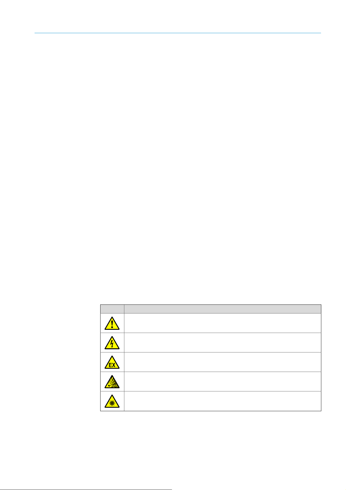
1.5.1 Warning symbols
Symbol Significance
Hazard (general)
Hazard by voltage
Hazard in potentially explosive atmospheres
Hazard through explosive substances/substance mixtures
Hazard by ultraviolet radiation (UV light)
8011703/XF49/V3-1/2019-09| SICK O PE RA T IN G I NS TR U C TI ON S | VICOTEC320
Subject to change without notice
7
Page 8

1 ABOUT THIS DOCUMENT
1.5.2 Information symbols
Symbol Significance
Important technical information for this product
Important information on electric or electronic functions
1.5.3 Warning levels and signal words
DANGER:
Risk or hazardous situation which will result in severe personal injury or death.
WARNING :
Risk or hazardous situation which could result in severe personal injury or death.
CAUTION:
Risk or hazardous situation which could result in less severe or minor injuries.
NOTICE:
Hazard which could result in property damage.
Note:
Hints
1.6 Data integrity
SICK AG uses standardized data interfaces such as standard IP technology, in its products.
The focus here is on the availability of the products and their properties.
SICK AG always assumes that the customer is responsible for the integrity and confidentiality of data and rights involved in connection with using the products.
In all cases, the customer is responsible for the implementation of safety measures suitable for the respective situation, e.g., network separation, firewalls, virus protection and
patch management.
8
8011703/XF49/2019-09| SICKO PE RA T IN G I NS TR U CT IO N S | VICOTEC320
Subject to change without notice
Page 9
2For your safety
2.1 Basic safety information
Read and always observe the safety and warning information in these Operating Instructions.
WARNING: Hazards thro ugh defe ctive devic e
The VICOTEC320 is likely to be unsafe when it:
● Shows visible damage on the outside.
● Has been penetrated by moisture.
● Has been stored or operated under irregular conditions.
When safe operation is no longer possible:
▸ Put the VICOTEC320 out of operation, separate all connectors from the
power supply and secure against unauthorized commissioning.
WARNING: Risk of explosions through explosive sample gas
▸ Do not use the VICOTEC320 to measure explosive, combustible or
flammable gases.
FOR YOUR SAFETY 2
WARNING: Explosion hazard in potentially explosive atmospheres
▸ Do not use the VICOTEC320 in potentially explosive atmospheres.
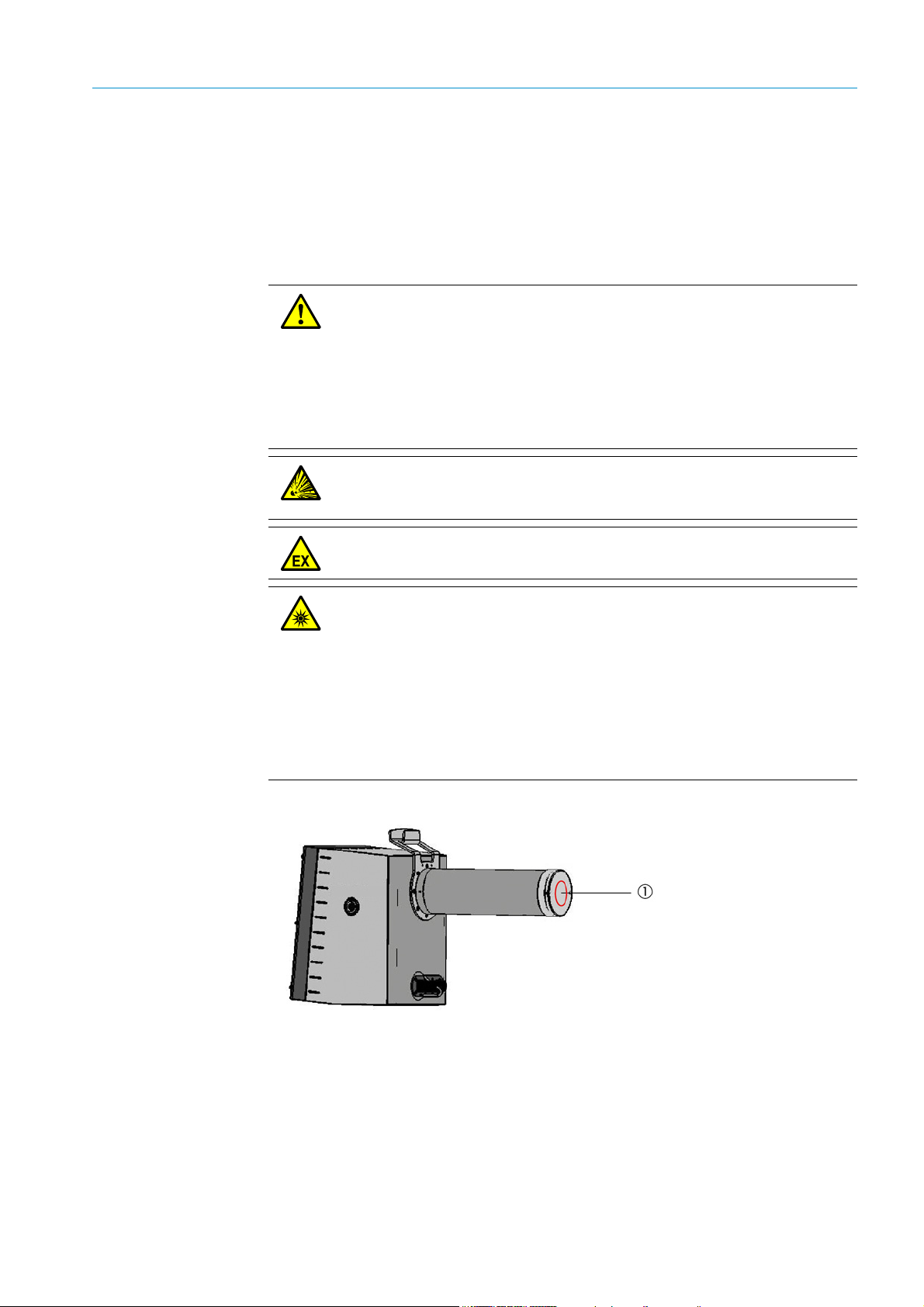
CAUTION: Eye injuries caused by improper handling of UV or blue light beams
The UV beam of the deuterium lamp or the blue light beam of the LED can
cause serious injuries through direct eye and skin contact. This results in the
following safety measures when working on the switched on device with access
to the light beam exit:
▸ Always wear UV protective goggles (in accordance with standard EN 170)
▸ The UV goggles do not provide protection against injuries caused by blue
light beams, therefore switch the LED off when working.
▸ Use the lamps only when they are perfectly safe. Operation is not allowed
when the lamp, supply lines or operating parts are visibly damaged.
Fig. 1: Sender/receiver unit
1 Light beam exit
8011703/XF49/V3-1/2019-09| SICK O PE RA T IN G I NS TR U C TI ON S | VICOTEC320
Subject to change without notice
9
Page 10

2 FOR YOUR SAFETY
2.2 Intended use
Devices of the VICOTEC320 series only serve continuous measurement of concentrations
of certain gases, visibility and the temperature in the atmosphere in road tunnels.
2.3 Responsibility of user
▸ Only put the VICOTEC320 into operation after reading the Operating Instructions.
▸ Observe all safety instructions.
▸ If there is something you do not understand: Contact SICK Customer Service.
Designated users
All operators of the VICOTEC320 should be specifically trained on this device, knowledgable
of relevant regulatio ns, and able to assess potential hazards related to its operation.
The VICOTEC320 may only be maintained by persons properly instructed on the tasks
assigned, possible risks and protective measures.
Operation
The device may only be operated by authorized persons who, based on their training on,
and knowledge of the specific device, as well as knowledge of the relevant regulations can
assess the tasks given and recognize the hazards involved.
Installing and maintaining
Skilled persons are required for installation and maintenance.
Please observe the information at the beginning of the respective Sections.
Correct use
▸ Only operate the VICOTEC320 according to the intended use (see “Intended use”,
page 10).
▸ Follow all specifications in these Operating Instructions and only operate the
VICOTEC320 as described in these Operating Instructions.
Contact your local SICK representative before performing any work described where the
information in these Operating Instructions is inadequate or capable of being misunderstood.
▸ Keep passwords in a separate, safe place and secure against unauthorized use.
▸ Pay attention to the prescribed maintenance work.
▸ Do not change any settings on or in the device and do not modify any components when
such changes are not described in these Operating Instructions or in documents referred
to in these Operating Instructions.
Special local requirements
▸ Observe the local laws, regulations and company internal operating instructions
applicable at the installation location.
Retention of documents
10
These Operating Instructions:
▸ Must be available for reference.
▸ Must be passed on to new owners.
8011703/XF49/2019-09| SICKO PE RA T IN G I NS TR U CT IO N S | VICOTEC320
Subject to change without notice
Page 11
3 Product description
3.1 Product identification
Product name: VICOTEC320
Manufacturer:
3.1.1 Type plate
The type plate is located at the following positions:
Device Type plate location
Sender/receiver unit
Reflector
Connection unit
PRODUCT DESCRIPTION 3
SICK AG
Erwin-Sick-Str. 1 · D-79183 Waldkirch · Germany
Outside: Next to the connections
Inside: At the bottom of the left enclosure side
Outside: Next to the connections
Inside: At the middle of the right enclosure side
Outside: At the top of the right enclosure side
Inside: Next to the connections
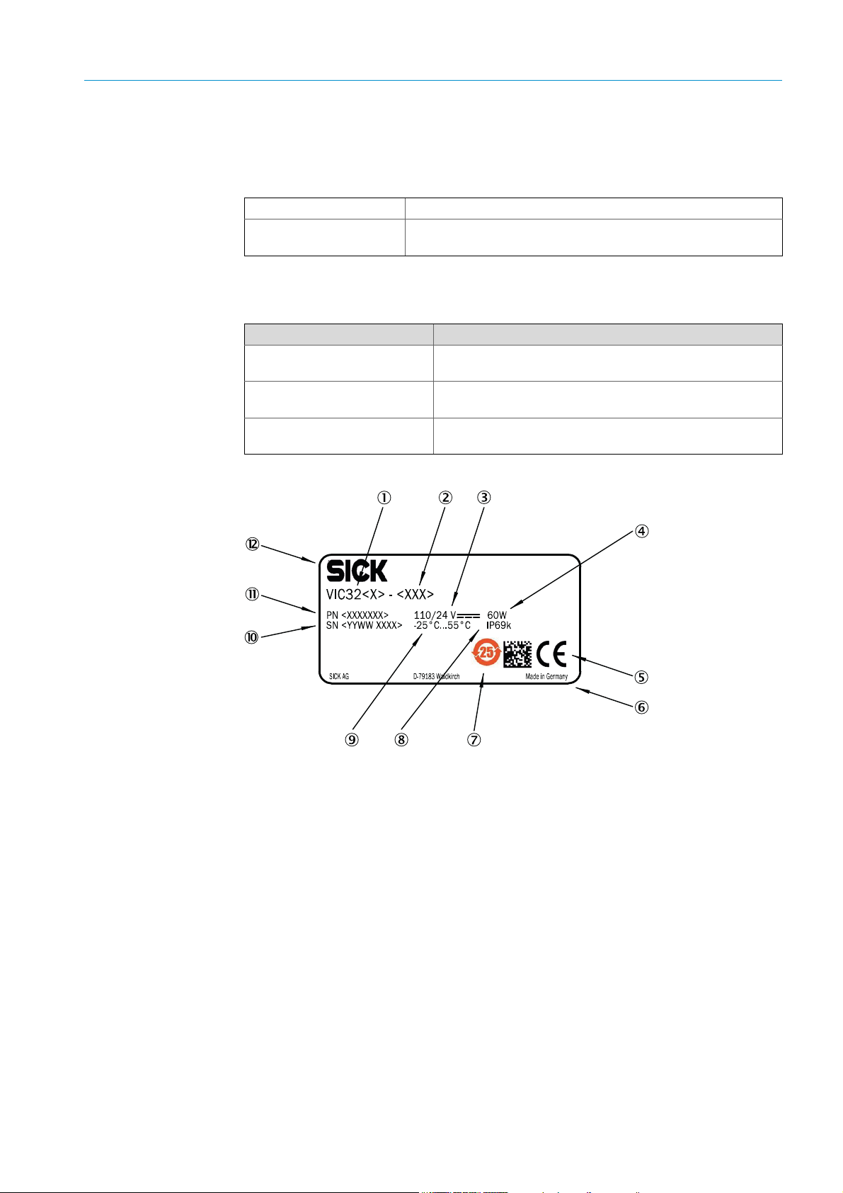
Fig. 2: Type plate
1 Device name
2Type code
3Voltage supply
4 Max. power input according to IEC61010-1
5Bar code
6 CE label
7 China RoHS
8 Degree of protection (IP code)
9 Ambient temperature
10 Serial number
11 Material number
12 Company logo
8011703/XF49/V3-1/2019-09| SICK O PE RA T IN G I NS TR U C TI ON S | VICOTEC320
Subject to change without notice
11
Page 12

3 PRODUCT DESCRIPTION
3.2 Product features
● Fast, representative local measurement
● Very low detection limits for NO and NO
●
Automatic function monitoring and zero adjust
● Independent maintenance prompt when contaminated
● Very sturdy design: IP 69K, stainless steel 1.4571
● Compatible to assembly consoles and measuring path lengths of the VICOTEC 410 from
SICK
3.3 Device variants
The following device variants are available depending on the measuring task and the
application:
Variant Measured components
VICOTEC 321 Measurement of visibility and NO
VICOTEC 322 Measurement of visibility and NO
VICOTEC 323 Measurement of visibility, NO and NO
VICOTEC 325 Measurement of visibility, NO, NO2 and NOx (option: CO)
2
2
2
The device variants differ with respect to the following:
● Measurable components
● Connection unit interfaces
The sender/receiver unit and the reflector are available for the following measuring
distances:
● 10 m
The connection unit is available with the following interfaces:
● Analog/digital
● Ethernet
● The connection unit can contain an optional CO sensor (electrochemical cell)
3.4 Special features
● Operating hour meter for sender lamp and logbook function
● High-precision adjustment through automatic mirror tracking
● Integrated ambient temperature measurement
● Reflector, heated
● Communication via CAN System bus or Ethernet (optional)
12
8011703/XF49/2019-09| SICKO PE RA T IN G I NS TR U CT IO N S | VICOTEC320
Subject to change without notice
Page 13
3.5 Layout and function
PRODUCT DESCRIPTION 3
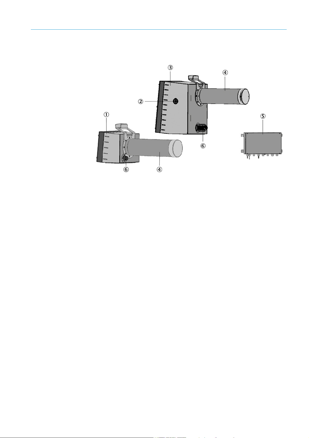
Fig. 3: Layout of measuring device components
1Reflector
2 LED matrix to signal automatic beam tracking
3 Sender/receiver unit
4 Dust protection tube
5 Connection unit
6 Plug connections
3.5.1 Functional principle
The VICOTEC320 is a sensor system for continuous measurement of NO, NO
(option) concentrations as well as visibility and temperature in road tunnels.
The following functional principles are used:
● NO, NO
● CO: Electrochemical cell
● Visibility: Transmission measurement with blue LED
: DOAS (Differential Optical Absorption Spectroscopy)
2
and CO
2
8011703/XF49/V3-1/2019-09| SICK O PE RA T IN G I NS TR U C TI ON S | VICOTEC320
Subject to change without notice
13
Page 14

4 PROJECT PLANNING
4 Project planning
4.1 Assembly project planning
4.1.1 Arrangement along the tunnel section
The number and distribution of measuring points depends on the ventilation system used.
Single factors are:
● Type of tunnel profile
● Section route
● Ventilation system design
● Number and arrangement of fans
● Regional regulations
Measuring point selection depends primarily on the following criteria:
● A combination of VICOTEC320 with VICOTEC 410 or VISIC100SF is recommended for
optimum measuring results.
● The recommended distance between visibility measurements depends on whether
these are also to be used for smoke detection:
– Without smoke detection: ≤ 400 m
– With smoke detection: ≤ 150 m
● We recommend VISIC50SF for smoke detection.
● An even spread along the tunnel length is recommended for semi and transverse
ventilation, with at least 2 measuring points per ventilation section.
● NO/NO
preferably at the tunnel exit in tunnels with one-way traffic.
● Two-way traffic can still arise in tunnels with one-way traffic. It is therefore recommended
to install at least 3 measuring points for visibility in tunnels with lengthwise ventilation:
one each about 150 m from the entrance and at least one in the middle of the tunnel.
● It is recommended to install additional fog sensors (e.g. VISIC620) near the tunnel
portals when there is a risk that fog can be sucked into the tunnel. Dust particles acting
as additional condensation crystals can strengthen the fog effect in the tunnel sections.
Fog moisture overlays visibility due to dust particles. Fog sensors serve to prevent fog
drifts being sucked into the tunnel. Alternately, visibility can be measured at the tunnel
portals using measuring devices (e.g. VISIC100SF or VICOTEC450) that heat the air
sucked in and therefore evaporate fog moisture.
● When the tunnel roadway curves, ensure that the measuring beam between single
sensors is not interrupted by the tunnel wall, fixtures or vehicles passing each other (see
see “Arrangement with special prerequisites”, page 16).
can be measured every 400 – 1000 m. Position the measuring points
2
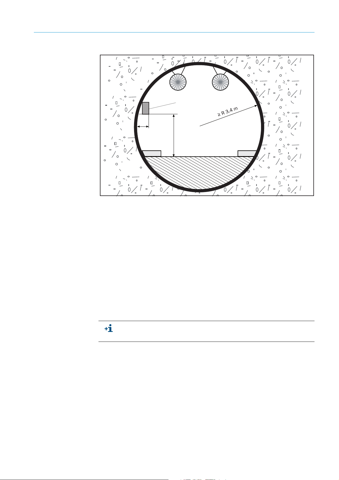
4.1.2 Arrangement in cross-section profile
Particle concentration distribution in a tunnel is generally very even across the profile
cross-section during traffic movement. Traffic flows and lengthwise flows through natural
ventilation and the piston effect of vehicle movement in separate tunnel sections for each
direction effect rapid swirling of the air in the tunnel. The turbulence behind vehicles
strengthens this effect.
The height is not critical due to excellent swirling. A fitting height between 2.8 and
4.5 meters is aimed at. The sensors contaminate faster when fitted lower and the
maintenance effort increases when the sensors are fitted higher.
14
8011703/XF49/2019-09| SICKO PE RA T IN G I NS TR U CT IO N S | VICOTEC320
Subject to change without notice
Page 15
PROJECT PLANNING 4
VICOTEC
320 sensor
2.8 … 4.5 m
400
Fig. 4: VICOTEC320 fitting height
Fitting location selection of the respective sensor pairs depends primarily on the following
criteria:
● Mount the sensors at a safe distance from traffic movement (see for example Section 2
of the German “Richtlinie für die Ausstattung und den Betrieb von Straßentunneln
RABT”, version 2006 (Regulations governing equipping and operating road tunnels)).
● Good access for maintenance and checking work must be ensured. Locate the sensors
in a protected recess when possible.
● Do not locate sensors in close vicinity to ventilators or in the fresh air flow from blowout
units so that the measured value records the effective concentration ratios.
● The measuring beam must run lengthwise between sensors and must not be hindered
by fixtures or vehicles passing each other. Fixtures that shine (e.g. emergency exit signs)
should be at least 1 m from the optical axis.
● No reflecting paint should be on the wall between sensors.
● Maintain a distance of 10
● Plan sufficient clearance to be able to flap or remove the enclosure cover.
Measured values of gases are kept constant at first when the light beams are
interrupted. A malfunction message is sent to the evaluation unit when interruptions
last lo nger than two minutes.
±
0.1
m between both sensors.
Fitting options:
● Both sensors on a wall in a recess (recommended).
● Both sensors on a wall above the side strip; requires safety measures for maintenance
work in cramped conditions.
8011703/XF49/V3-1/2019-09| SICK O PE RA T IN G I NS TR U C TI ON S | VICOTEC320
Subject to change without notice
15
Page 16
4 PROJECT PLANNING
A
R
1
A
R
2
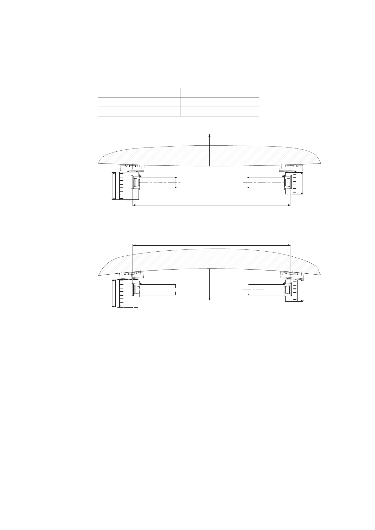
4.1.3 Arrangement with special prerequisites
Tunnel curvature
The sensors can be used with tunnel curvatures up to the following curve radiuses:
Measuring section (A) 10 m
Inner radius (R
Outer radius (R
) Min. 58 m
1
) Min. 147 m
2
Fig. 5: Fitting sensors on the inner curve wall
Fig. 6: Fitting sensors on the outer curve wall
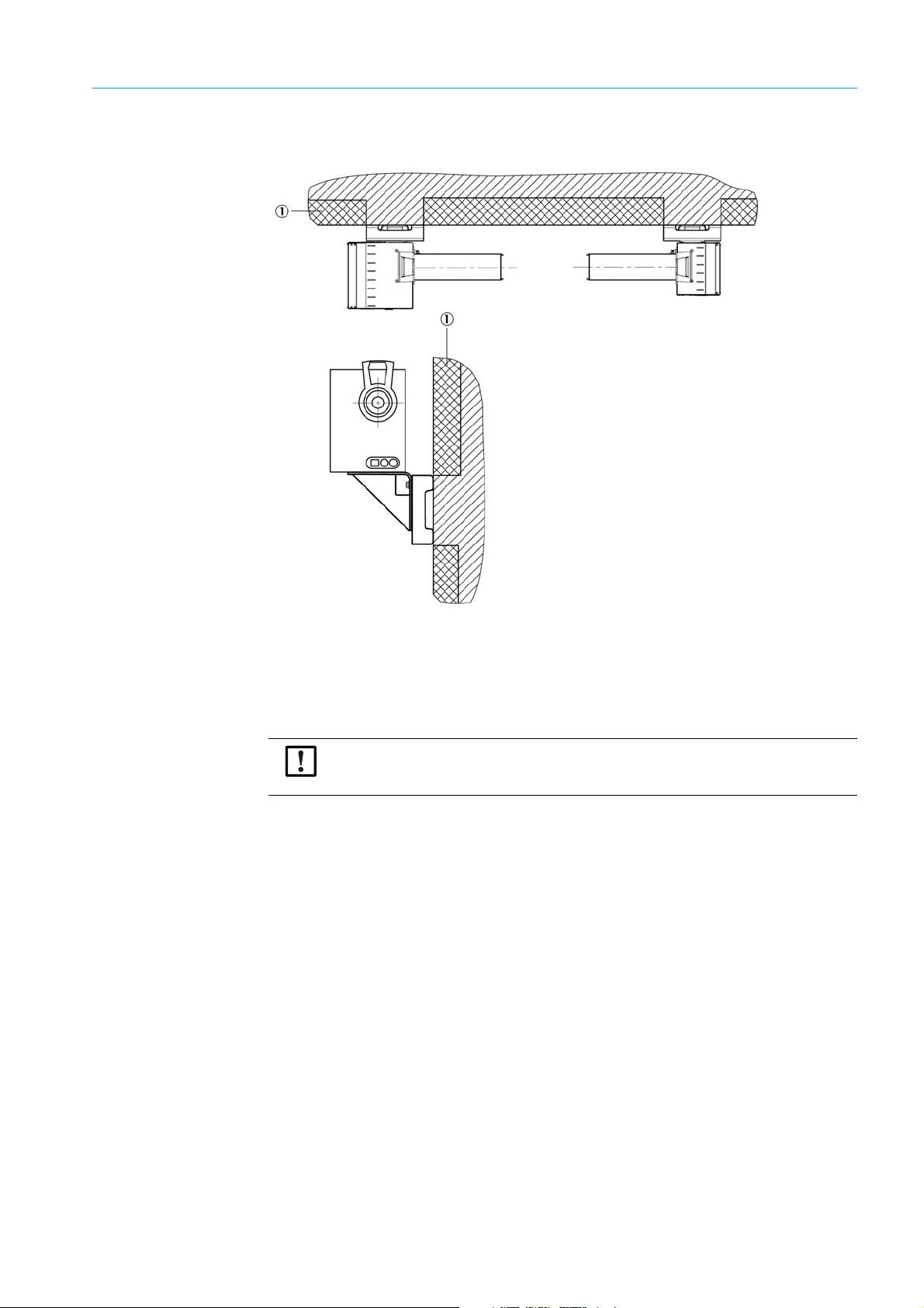
Tunnel with sound insulation wall
Provide appropriate assembly bases onsite when fitting sensors on a tunnel wall with
sound insulation.
The assembly bases must provide a firm base suitable for reliable sensor fitting.
16
8011703/XF49/2019-09| SICKO PE RA T IN G I NS TR U CT IO N S | VICOTEC320
Subject to change without notice
Page 17
PROJECT PLANNING 4
Fig. 7: Fitting sensors with sound insulation
1 Sound insulation
4.2 Electrical installation project planning
Observe the relevant safety regulations during all installation work. Take suitable
protective measures against all possible local risks or those arising in connection with
the system (see “For your safety”, page 9).
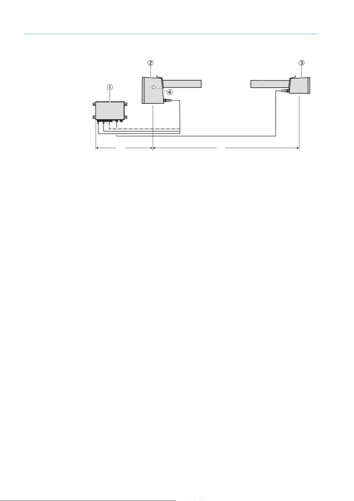
● Sender/receiver unit (2) must always be fitted on the left (see Fig. “Sensor arrange-
ment”, page 18), so that visor (4) is accessible.
● Position connection unit (1) so that it can be connected to the sender/receiver unit with
a 1 m long cable.
● It must be possible to separate every device singly from the power supply system, e.g.
using a switch or circuit breaker.
8011703/XF49/V3-1/2019-09| SICK O PE RA T IN G I NS TR U C TI ON S | VICOTEC320
Subject to change without notice
17
Page 18
4 PROJECT PLANNING
Fig. 8: Sensor arrangement
1 Connection unit
2 Sender/receiver unit
3Reflector
4Visor
A Measuring path (10
B Max. 0.7 m (cable leng th max. 1 m)
B A
±0.1
m)
18
8011703/XF49/2019-09| SICKO PE RA T IN G I NS TR U CT IO N S | VICOTEC320
Subject to change without notice
Page 19
5 Installation
5.1 Tools required
Apart from standard tools (such as drill, water level, tape measure), you also need the
following tools for the installation:
–8 mm drill bit
–15 mm drill bit
–Blowout pump for dowel holes
–18 mm Allen key
–19 mm Allen key
–Jaw wrench, 22 mm
–Torque wrench
–Rubber or plastic hammer
– Two laser adjustment units (see “Accessories”, page 68)
5.2 Material required
– 2 stainless steel assembly consoles incl. fixing accessories
– Connection lines (see “Connection lines”, page 26)
INSTALLATION 5
5.3 Preparing the installation location
CAUTION: Accident risk through inadequate fastening of the device
▸ Consider the weight of the device when selecting fastenings.
▸ Check the load capability/state of the wall/rack on which the device is to be fitted.
Preparatory actions
▸ Secure the place of work
▸ Provide adequate lighting and power
▸ Provide a jack lift or stable ladder with clearance to wall
5.4 Transport
Only use the packing provided by SICK to transport sensors. Warranty claims are void
when this is not observed.
The packing can be obtained from SICK free of charge when required.
5.5 Scope of delivery
Included in scope of delivery:
● Sender/receiver unit (incl. screws for fastening on assembly console)
● Reflector (incl. screws for fastening on assembly console)
● Connection unit (incl. dowels and screws for wall fitting)
● Connection lines from the connection unit to the sender/receiver unit and to the
reflector
● Protective covers
Keep protective covers. Use protective covers when the equipment is put out of
operation for a short time (e.g. during tunnel cleaning).
8011703/XF49/V3-1/2019-09| SICK O PE RA T IN G I NS TR U C TI ON S | VICOTEC320
Subject to change without notice
19
Page 20
5 INSTALLATION
Not included in scope of delivery:
● Stainless steel assembly consoles for the sensors
5.6 Assembly
Assembly work must only be carried out by skilled persons familiar with the assembly work.
5.6.1 Fitting the assembly consoles
The assembly consoles comprise 3 parts:
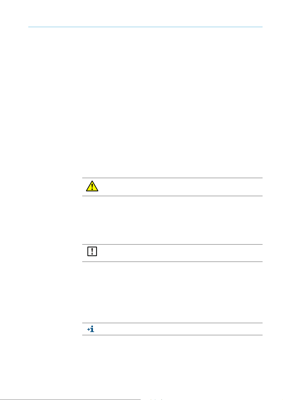
Fig. 9: Assembly console
1 Wall holder for wall fitting
2 Angle bracket to fasten the sensor
3Angle bracket screws
Two angle bracket screws fasten the wall holder and the assembly console together. The
angle bracket can be swiveled up to ±7.5° to compensate any assembly unevenness.
Observe the following points during assembly:
▸ Observe local valid safety measures.
▸ Only use high-strength and absolutely non-corrosive fastening material made of
stainless steel because the tunnel atmosphere is highly corrosive.
▸ Ensure there is enough space to remove the tube and device cover.
▸ Keep the length of the measuring section as exact as possible. Record small
deviations in the Assembly protocol.
▸ Mount both assembly consoles at the same height. Height differences in the optical
axis can be compensated later by swiveling the angle bracket.
▸ Align both assembly consoles at the same tilt angle to the tunnel wall. Different tilt
positions to the tunnel profile make the following sensor alignment difficult. Insert
washers under the wall holder when necessary.
Procedure
1 Determine the installation location for the assembly consoles according to the project
planning.
2 Drill the wall holder openings according to the Drilling plan, see see Fig. “Wall holder
assembly drilling plan”, page 21.
3 Insert dowels or wall ties according to the manufacturer's assembly specifications (walls
must be made of at least C20/25 to C25/30 concrete).
20
8011703/XF49/2019-09| SICKO PE RA T IN G I NS TR U CT IO N S | VICOTEC320
Subject to change without notice
Page 21
INSTALLATION 5
105105
210210
A
182
182
15
0
15
0
15
0
15
0
15
0
15 x 50
+2
0
15
0
4 Screw the wall holder on and tighten the screws with 70 Nm according to the
manufacturer's assembly specifications, use a torque wrench as necessary.
5 Screw the consoles on provisionally at first.
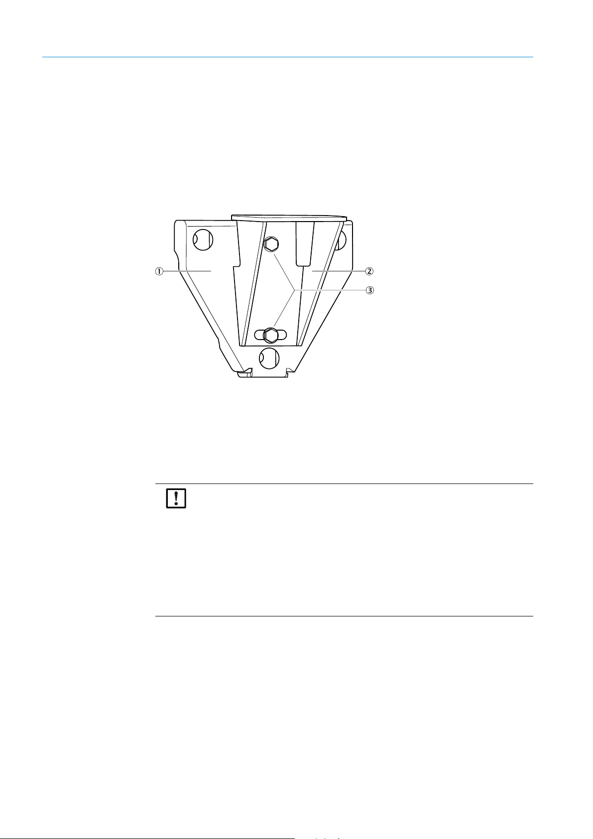
Fig. 10: Wall holder assembly drilling plan
Tolerances for measuring path A
±0.1
m
10
5.6.2 Fitting the VICOTEC320 sensors
1 Position the sender/receiver unit on the left assembly console and screw it on lightly
with both the retaining screws included in the delivery.
2 Position the reflector on the right assembly console and screw it on lightly with both the
retaining screws included in the delivery.
3 Screw a laser adjustment unit on each sensor above the tube using both knurled-head
screws.
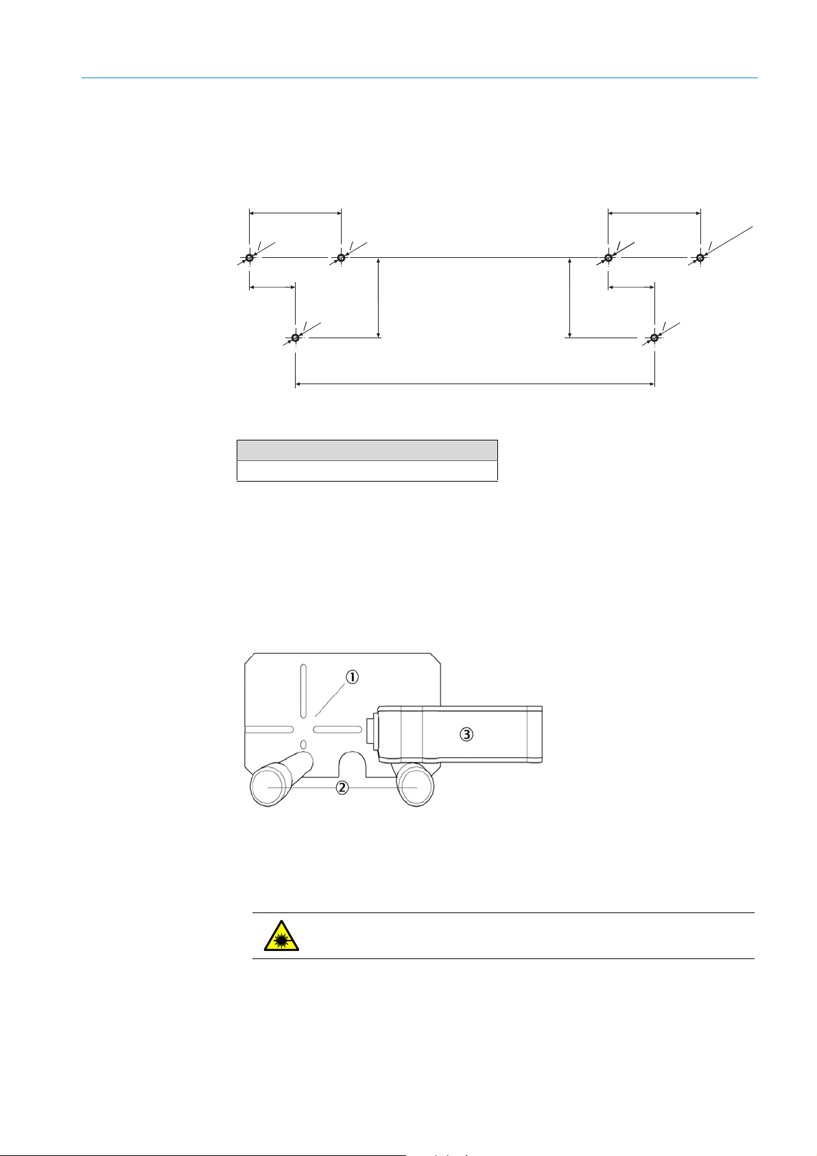
Fig. 11: Laser adjustment unit
1 Crosshair
2Knurled-head screws
3 Adjustment laser
WARNING: Laser class 2
▸ Laser radiation – do not look in the beam.
4 Switch on the laser adjustment unit on the reflector.
8011703/XF49/V3-1/2019-09| SICK O PE RA T IN G I NS TR U C TI ON S | VICOTEC320
Subject to change without notice
21
Page 22

5 INSTALLATION
5 Align the sensor horizontally so that the laser beam strikes the vertical line of the cross-
hair of the other laser adjustment unit see Fig. “Laser adjustment unit”, page 21). To do
this, tap very lightly against the front lower edge of the sensor enclosure with a rubber
hammer (see Fig. “Horizontal sensor alignment”, page 22).
Fig. 12: Horizontal sensor alignment
1 Retaining screws
2Angle bracket screws
6 Tighten both retaining screws of the sensor with 45 Nm, use a torque wrench as
necessary.
7 Slightly loosen the angle bracket screws.
8 Align the sensor vertically so that the laser beam strikes the horizontal line of the cross
hair of the other laser adjustment unit (see Fig. “Laser adjustment unit”, page 21). To do
this, tap very lightly against the front lower edge of the angle bracket with a rubber
hammer (see Fig. “Vertical sensor alignment”, page 22).
22
Fig. 13: Vertical sensor alignment
9 Tighten the angle bracket, use a torque wrench as necessary.
10 Check again whether the laser beam strikes the crosshair and correct as necessary.
11 Switch the laser adjustment unit off.
8011703/XF49/2019-09| SICKO PE RA T IN G I NS TR U CT IO N S | VICOTEC320
Subject to change without notice
Page 23

12 Repeat steps 5 to 11 on the opposite sensor and laser adjustment unit.
105105
210210
A
182
182
15
0
15
0
15
0
15
0
15
0
15 x 50
+2
0
15
0
13 Unscrew and remove the laser adjustment unit.
5.6.3 Fitting the connection unit
Position the connection unit so that it can be connected to the sender/receiver unit with
the 1 m long cables.
1 Determine the installation location for the connection unit according to the project
planning.
2 Drill the openings according to the Drilling plan, see Fig. “Connection unit assembly drill-
ing plan”, page 23.
3 Insert dowels or wall ties according to the manufacturer's assembly specifications (walls
must be made of at least C20/25 to C25/30 concrete).
4 Screw the connection unit on.
INSTALLATION 5
Fig. 14: Connection unit assembly drilling plan
8011703/XF49/V3-1/2019-09| SICK O PE RA T IN G I NS TR U C TI ON S | VICOTEC320
Subject to change without notice
23
Page 24

5 INSTALLATION
5.7 Electrical installation
WARNING : Hazard by voltage.
▸ Only allow an authorized electrician to work on the electric system.
▸ Observe the relevant safety regulations during all installation work.
▸ Take suitable protective measures against local risks and those arising from the
system.
WARNING: Endangerment of electrical safety during installation and
maintenance work when the power supply is not switched off
An electrical accident can occur during installation and maintenance work when the
power supply to the device or lines is not switched off using a power isolating switch/
circuit breaker.
▸ Before starting the work on the device, ensure the power supply can be switched off
using a power isolating switch/circuit breaker in accordance with DIN EN 61010.
▸ Make sure the power isolating switch is easily accessible.
▸ An additional disconnecting device is mandatory when the power disconnector
switch cannot be accessed or only with difficulty after installation of the device
connection.
▸ After completion of the work or for test purposes, the power supply may only be
activated again by authorized personnel complying with the safety regulations.
WARNING: Endangerment of electrical safety through power cable with
incorrect rating
Electrical accidents can occur when the specifications for replacement of a removable
power cable have not been adequately observed.
▸ Always observe the exact specifications in the Operating Instructions (Technical data
Section) when replacing a removable power cable.
5.7.1 Electrical protection
– Insulation: Class of protection 1 in accordance with EN 61140
– Insulation coordination: Overvoltage category II in accordance with EN61010-1
– Contamination: Degree of contamination II in accordance with DIN EN 61010-1
CAUTION: Device damage through incorrect or non-existing grounding
During installation and maintenance work, it must be ensured that the protective
grounding to the devices and/or lines involved is effective in accordance with
EN 61010-1.
Note: Responsibility for system safety
The person setting the system up is responsible for the safety of the system in which the
device is integrated.
24
8011703/XF49/2019-09| SICKO PE RA T IN G I NS TR U CT IO N S | VICOTEC320
Subject to change without notice
Page 25

5.7.2 Connecting the sensors to the connection unit
1 Plug the connection lines that are mounted firmly on the connection unit in the
corresponding sockets of the sender/receiver unit.
2 Connect the connection line to the reflector with the connection unit:
Observe the wiring diagram on the rear of the cover.
a) Open the connection unit.
b) Unscrew M screw fitting for W3 (1).
INSTALLATION 5
c) Pull the connection line through the M screw fitting and connect to the W3
connection (2).
d) 35
e) Tighten the M screw fitting tight with a jaw wrench.
3 Plug the connection line into the reflector.
4 Fasten the connection lines to the tunnel wall.
8011703/XF49/V3-1/2019-09| SICK O PE RA T IN G I NS TR U C TI ON S | VICOTEC320
Subject to change without notice
25
Page 26

5 INSTALLATION
5.7.3 Connection unit cabling
Connection lines
The following connection lines can be used:
For Line/type Max. length Cross-section
Energy supply:
115/230 V AC; 50/60 Hz
Digital input A2Y(L)2Y
Relay outputs A2Y(L)2Y
Etherne t
Analog outputs:
0…20 mA
–Category5 copper
line according to
ANSI/TIA -568
–Fiber optic cable
Screened and twisted
in pairs
Dependent on cable
resistance
Dependent on cable
resistance
Dependent on cable
resistance
– 100 m
– Up to about 5 km
according to type
Dependent on cable
resistance
3 x 1.5 mm
2 x 2 x 0.75 mm
4 x 2 x 0.75 mm
4 x 2 x 0.75 mm
2
2
2
2
Warranty claims are void when you use cables not released by SICK for use with the
VICOTEC320 (see “Connection lines”, page 26).
Cabling of voltage supply
Set the power voltage for the connection unit to 115 V or 230 V before connecting the unit
to the power supply system.
Use slide switch (1) in the connection unit to the correct voltage.
26
Fig. 15: Slide switch and voltage supply
1 Slide switch for voltage selection
2 Terminals for power supply
▸ Connect voltage supply according to terminal designation (L1/N/PE).
8011703/XF49/2019-09| SICKO PE RA T IN G I NS TR U CT IO N S | VICOTEC320
Subject to change without notice
Page 27

Fig. 16: Connection options for peripherals
1 Sender/receiver unit connection (2x)
2 Reflector connection
3 Ethernet (when used)
4 Input and/or output signals (when used)
5Voltage supply
INSTALLATION 5
Input/output cabling for analog/digital variants
The CAN bus terminator must be set to “ON” (LED must be on: see Fig. “Location of
LEDs in the connection unit for the analog/digital variant”, page 30)
The inputs and outputs of the connection unit are assigned as follows:
Input or output Assignment
Analog
Output 1 Visibility
Output 2 Temperature
Output 3 NO
Output 4 NO
Output 5 CO
Output 6 NO
Digital
Relay 1
Relay 2
Relay 3
2
x
Operation/fault for NO, NO
● Operation: Relay is closed
● Fault: Relay is open
, visibility
2
Maintenance request signal
● No maintenance request: Relay is open
● Maintenance request (e.g.: contamination): Relay is closed
Measuring operation signal
● Measuring operation: Relay is open
● Not in measuring operation (e.g. during maintenance, adjust-
ment etc.): Relay is closed
8011703/XF49/V3-1/2019-09| SICK O PE RA T IN G I NS TR U C TI ON S | VICOTEC320
Subject to change without notice
27
Page 28

5 INSTALLATION
Input or output Assignment
Operation/fault for CO (option)
Relay 4
● Operation: Relay is open
● Fault: Relay is closed
Input 1 Maintenance mode (measured values frozen)
I Analog Out
State
Analog
Output
0...20mA
Load
500Ω
12
Shield
AO1 AO2
- -
11 21
12 22
13 23
14 24
11 21
12 22
13 23
14 24
State
Analog
Output
0...20mA
Load
500Ω
12
12
34
Shield
AO1 AO2
- -
DO1 DO2
DO3 DO4
11 21
12 22
13 23
14 24
State
Digital
Output
Signal
Relais
State
Digital
Input
1
3
DI1 DI2
DI3 DI4
11 21
12 22
13 23
14 24
II Analog Out
2
4
III Digital Out
Operation/Fault
Maintenance call
Not in measuring
mode
IV Digital In
Maintenance
Visibility +
Visibility -
Temperature +
Temperature -
Not assigned
Not used
Not used
Not used
NO +
NO -
NO2 +
NO2 -
I - 11
I - 12
I - 21
I - 23
II - 11
II - 12
II - 21
II - 23
III - 11
III - 12
III - 22
III - 21
III - 14
III - 13
III - 23
III - 24
IV - 11
IV - 12
IV - 21
IV - 22
IV - 13
IV - 14
IV - 21
IV - 22
28
internal
I II III IV
external
Fig. 17: I/O modules and circuit diagram of analog modules without CO and NOx-inlets/outlets
8011703/XF49/2019-09| SICKO PE RA T IN G I NS TR U CT IO N S | VICOTEC320
Subject to change without notice
Page 29

INSTALLATION 5
Fig. 18: I/O modules and circuit diagram of analog modules with CO and NOx inlets/outlets
Module LED Significance
Digital out Green Active
Digital in Green Contact closed
Analog out Green Actual current value = rated current value
≤
Analog in
Green
Off
0mA
I
≥ 22 mA
on
Ion < 22 mA
▸ Connect the power supply.
Checking cabling
Correct cabling can be checked as follows (see Fig. “Location of LEDs in the connection
unit for the analog/digital variant”, page 30):
● The gateway LEDs are green (State, CAN, I/O).
● The error LED on the gateway is off.
● The 120 V LED and the 24 V LED are green.
● The status LEDs of the I/O module blink green.
● The reflector heating LED is green.
● The alignment LEDs on the sender/receiver unit flash sequentially.
8011703/XF49/V3-1/2019-09| SICK O PE RA T IN G I NS TR U C TI ON S | VICOTEC320
Subject to change without notice
29
Page 30

5 INSTALLATION
Fig. 19: Location of LEDs in the connection unit for the analog/digital variant
1 Gateway state Green LED blinks in operation
Red LED on: CAN bus is connected but not initialized
2 I/O module state LED1 blinks in I²C bus cycle pulse
LED2 blinks in data transfer cycle pulse
3 Gateway CAN LEDs blink: Data transfer via CAN bus
LEDs on: No CAN bus connected
4 Gateway I/O LED1 blinks in I²C bus cycle pulse
LED2 blinks in data transfer cycle pulse
5 Gateway error LED on: No I/O module found on gateway
or one or more modules failed during operation
6120 V
724 V
8 Reflector heating 24 V
9 CAN bus connection LED is green: CAN bus terminator is activated.
30
8011703/XF49/2019-09| SICKO PE RA T IN G I NS TR U CT IO N S | VICOTEC320
Subject to change without notice
Page 31

Connecting the Ethernet cable for Ethernet variant
INSTALLATION 5
Fig. 20: Ethernet connection
▸ Lead the Ethernet cable through the nearest cable gland (see Fig. “Connection options
for peripherals”, page 27) and plug into switch (1).
8011703/XF49/V3-1/2019-09| SICK O PE RA T IN G I NS TR U C TI ON S | VICOTEC320
Subject to change without notice
31
Page 32

6 COMMISSIONING
6 Commissioning
6.1 Necessary technical knowledge for commissioning
The commissioning must only be performed by authorized technicians and is described in
the Service Manual.
Wait two hours after commissioning until the system has heated up. It has then reached
a thermal balance and delivers measured values within the tolerance band.
6.2 Commissioning checklist
The up-to-date Operating Instructions must be available.
Please request the up-to-date commissioning checklist from SICK Service.
First enter the customer data.
6.2.1 Device data
Ente r the devic e data here.
6.2.2 Tunnel data
– Serial number: See type plate or SOPAS.
– Specify kind and type of process optics.
Enter location and measuring point here.
SOPAS supports the value of the active measuring path.
32
8011703/XF49/2019-09| SICKO PE RA T IN G I NS TR U CT IO N S | VICOTEC320
Subject to change without notice
Page 33

6.3 Alignment
COMMISSIONING 6
The mechanical alignment of the measuring device and the reflector must have already
been performed by using the laser adjustment units.
Fig. 21: Menu Adjustment / Alignment.
1 Open “Adjustment/Alignment” in the SOPAS menu tree.
Fine adjustment of horizontal alignment
1 Slightly loosen the retaining screws of the measuring device on the assembly console so
that the device can be moved.
2 Using a small plastic or rubber hammer, very carefully tap the position shown below (see
Fig. “Vertical sensor alignment”, page 34).
3 Tap until the VIS X value on the display reaches <0.15.
4 Tighten the retaining screws again.
8011703/XF49/V3-1/2019-09| SICK O PE RA T IN G I NS TR U C TI ON S | VICOTEC320
Subject to change without notice
33
Page 34

6 COMMISSIONING
Fig. 22: Horizontal sensor alignment
1 Retaining screws
2Angle bracket screws
Fine adjustment of vertical alignment
1 Slightly loosen the angle bracket screws.
2 Using a small plastic or rubber hammer, very carefully tap the position shown below (see
Fig. “Vertical sensor alignment”, page 34).
3 Tap until the VIS Y value on the display reaches <0.15.
4 Tighten the angle bracket screws again.
Fig. 23: Vertical sensor alignment
34
The LED grid in the visor of the sender/receiver unit shows the position of the light
beam in relation to the reflector center. After fine adjustment, one of the 3 x 3 LEDs in
the center of the grid should light.
If a LED outside the 3 x 3 LEDs in the center lights, fine adjustment must be performed
again.
8011703/XF49/2019-09| SICKO PE RA T IN G I NS TR U CT IO N S | VICOTEC320
Subject to change without notice
Page 35

6.4 Spectral analysis
Fig. 24: Menu Parameter/Spectral analysis
COMMISSIONING 6
1 Open “Parameter/Spectral analysis” in the SOPAS menu tree.
2 Enter the installation altitude (above sea level).
6.5 Visibility and smoke detection
Fig. 25: Menu Parameter/Visibility
1 Open “Parameter/Visibility” in the SOPAS menu tree.
>>>
Default setting: Smoke detection not activated.
Measured values of gases are kept constant at first when the light beams are
interrupted. A malfunction message is sent to the evaluation unit when interruptions
last lo nger than two minutes.
2 To activate smoke detection: Set checkmark.
A value above 22 mA is transmitted at the analog output when the light beams are
interrupted (quick drop of visibility). No malfunction message is output.
8011703/XF49/V3-1/2019-09| SICK O PE RA T IN G I NS TR U C TI ON S | VICOTEC320
Subject to change without notice
35
Page 36

6 COMMISSIONING
6.6 Signal outputs
Fig. 26: Menu Parameter\Signal output
1 Open “Parameter/Signal output” in the SOPAS menu tree.
2 Change the predefined setting when required.
6.7 Saving data
Fig. 27: SOPAS main window
1 Open “Project/Save as” in the SOPAS main window.
2 Specify project name and storage location.
36
8011703/XF49/2019-09| SICKO PE RA T IN G I NS TR U CT IO N S | VICOTEC320
Subject to change without notice
Page 37

7Operation
7.1 Operating the VICOTEC320
The VICOTEC320 runs automatically after commissioning and does not require further
operator intervention. You can however use the SOPAS ET software to change the
configuration or display measured values.
OPERATION 7
8011703/XF49/V3-1/2019-09| SICK O PE RA T IN G I NS TR U C TI ON S | VICOTEC320
Subject to change without notice
37
Page 38

8 USING THE VICOTEC320
8Using the VICOTEC320
8.1 Software SOPAS ET
The SOPAS ET software serves to set the VICOTEC320 parameters. The parameter records
can be stored as a Project file as well as archived on the PC. Measured values can also be
read out.
8.1.1 Functions (overview)
The Online Help of the SOPAS ET software (Help menu) describes the general function of
the software and how to use it.
● Menu language selection
● Setting up communication with the VICOTEC320
● Password protected configuration for different operator levels
● Output current measured values
● System diagnostics
The password can be found in the Annex, see “Password”, page 75.
8.1.2 Installing the SOPAS ET software
1 Start the PC and insert the Installation CD.
2 Call setup.exe directly from the CD when installation does not start automatically.
3 Follow the operating instructions to complete installation.
8.2 Using SOPAS ET
The SOPAS ET interface is described in the SOPAS ET Manual.
See menu: Help/SOPAS ET Manual.
8.2.1 Creating a connection
Connect data interfaces
1 Ensure the supply voltage of the VICOTEC320 is switched on.
2 Switch the PC on.
3 Make sure the WLAN is switched off.
4 Connect PC (Ethernet interface) and VICOTEC320 via Ethernet line.
5 Insert the network cable.
6 Wait until the laptop has initialized the Ethernet interface (approx. 1 min.)
Start the SOPAS ET software
1 Start the software.
>>>
The device should be found automatically and added to the project.
38
8011703/XF49/2019-09| SICKO PE RA T IN G I NS TR U CT IO N S | VICOTEC320
Subject to change without notice
Page 39

2 The IP address of the device must be adapted.
a) Click “Edit IP address”.
>>>
The TCP/IP settings window opens.
USING THE VICOTEC320 8
b) Record the current IP settings (if the device was logged off the customer network and
then has to be logged in again).
c) Select the [Automatic] button.
>>>
A corresponding IP address is displayed.
d) Confirm with [OK].
>>>
The IP address is sent to the device.
8011703/XF49/V3-1/2019-09| SICK O PE RA T IN G I NS TR U C TI ON S | VICOTEC320
Subject to change without notice
39
Page 40

8 USING THE VICOTEC320
3 Install device driver.
a) Click “Install device driver”.
b) Select the device driver source. Recommended: Select “Device upload”.
c) Confirm with [OK].
>>>
Driver is loaded from the device.
Setting device parameters
1 Double-click “Offline”.
>>>
The Go online window opens.
2 Select the “Read parameters” function.
3 Double-click the header
>>>
The device window opens.
40
8011703/XF49/2019-09| SICKO PE RA T IN G I NS TR U CT IO N S | VICOTEC320
Subject to change without notice
Page 41

Login to the device
1 Click “Login” at the top of the menu bar.
>>>
The login window opens.
2 Enter the desired user level “Authorized operator”.
3 Enter password (see “Password”, page 75).
4 Click [Login].
Integration in customer network
The sensor IP address of the device must be adapted to the customer network when
the VICOTEC320 is integrated in a network or connected to a customer WLAN
module.
1 Close the device window.
In the SOPAS main window
USING THE VICOTEC320 8
2 Click the button next to the IP address [pen].
>>>
The TCP/IP settings window opens.
8011703/XF49/V3-1/2019-09| SICK O PE RA T IN G I NS TR U C TI ON S | VICOTEC320
Subject to change without notice
41
Page 42

8 USING THE VICOTEC320
3 Enter the network information (to be provided by the customer) for the device in section
“Use the following IP settings”.
4 Confirm with [OK].
>>>
The Change TCP/IP settings window opens.
5 Confirm with [Yes].
>>>
The Change the TCP/IP settings of the device ... window opens.
6 Confirm with [Yes].
>>>
The settings are transferred to the device.
>>>
The Device not found window opens.
7 Confirm with [OK].
8 Connect the device with the customer network.
42
8011703/XF49/2019-09| SICKO PE RA T IN G I NS TR U CT IO N S | VICOTEC320
Subject to change without notice
Page 43
USING THE VICOTEC320 8
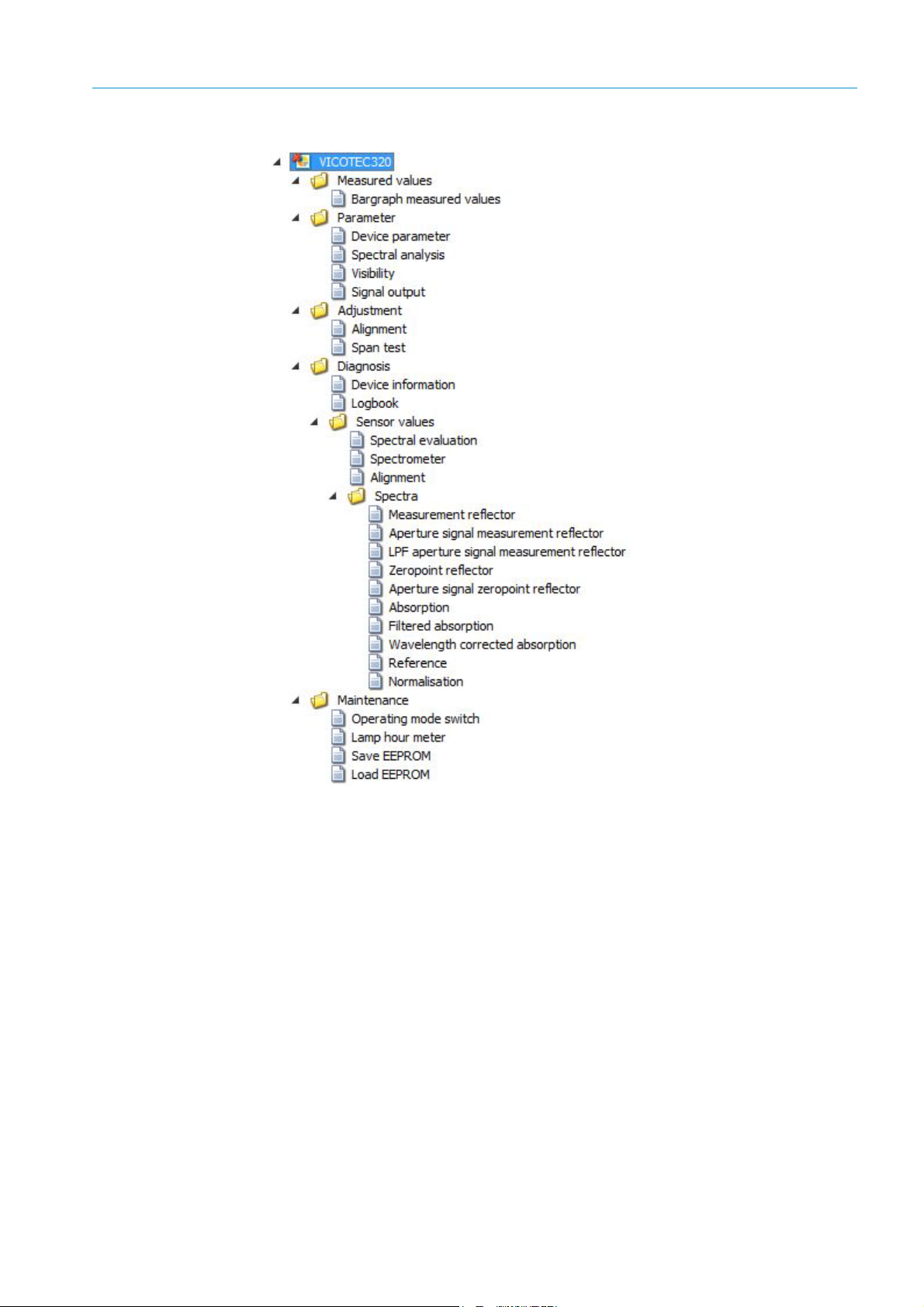
Fig. 28: Menu tree VICOTEC320
8011703/XF49/V3-1/2019-09| SICK O PE RA T IN G I NS TR U C TI ON S | VICOTEC320
Subject to change without notice
43
Page 44

8 USING THE VICOTEC320
8.2.2 Reading out the VICOTEC320 and operating manually
The corresponding operator level must first be selected to configure a device with the
SOPAS ET software. The SOPAS ET software runs in the operator level “Operator” after commissioning and parameters can only be read.
– To change the operating level to “Authorized operator”: Login via the [Login] button >
enter password (see “Password”, page 75).
– Double-click one of the functions in the project tree to start this function.
– To save all the data, select the “Export SDV file” command in the Device menu .
The following tabs are important for you; the other tabs are shown colored gray and are only
relevant for Service technicians.
Bargraph measured values
44
Fig. 29: Bargraph measured values
This screen shows whether the sensors are in measuring operation or whether a fault or
maintenance requirement exist.
Apart from that, the current measured values for visibility, temperature, NO, NO
and NOx
2
are displayed (depending on the device variant).
When fault or maintenance request is shown, the measurement triggering the fault or
maintenance request is shown next to the measured values.
The “Uncertain” LED next to the measured values signals that the measured value is
“uncertain” (e.g.: Calibration range exceeded. → Logbook).
8011703/XF49/2019-09| SICKO PE RA T IN G I NS TR U CT IO N S | VICOTEC320
Subject to change without notice
Page 45

Alignment
USING THE VICOTEC320 8
Fig. 30: Alignment
Nominal values
1 Offset <100
2 A,B,C,D: 250-500
The light beam is tracked automatically to the center of the reflector.
Manual alignment is only possible for authorized operators:
Device information
Menu: Diagnosis/Device information:
This screen shows the serial number, device process and operating hours of the sender
lamp.
8011703/XF49/V3-1/2019-09| SICK O PE RA T IN G I NS TR U C TI ON S | VICOTEC320
Subject to change without notice
45
Page 46

8 USING THE VICOTEC320
Logbook
All sensor messages are stored in the Logbook. Messages marked with a red dot are still
active, messages with a green dot are already completed.
Messages can be filtered according to type:
▸ Click on the dropdown box and select the type of message required.
Fig. 31: Logbook
Symbol Remark
Logbook fill level in %.
When the characters are
Warning mode: Further entries are not accepted.
Circular buffer mode: Oldest entries are overwritten.
Data storage:
Symbol
not crossed out
Symbol
crossed out
Circular buffer mode
Warning mode
Entries Number of entries of selected filter.
Filter for messages Only filtered messages are shown.
Reset Clear all entries.
- Show active failures
- Show all failures
- Show active maintenance request
- Show all maintenance requests
- Show active uncertain
- Show all uncertain
- Show active extended messages
- Show all extended messages
- Show active messages
- Show all messages
Classification
→
red
: The logbook is full.
: Compressed.
: Uncompressed.
Further on in this Table.
46
8011703/XF49/2019-09| SICKO PE RA T IN G I NS TR U CT IO N S | VICOTEC320
Subject to change without notice
Page 47

Symbol Remark
Export
(Only in SOPAS ET)
Update Update display of logbook entries.
Last Data Scroll back.
Next Data Scroll forward.
All entries selected via the filter (→ Further back in this Table) are saved on the PC as .log file.
Format: CSV (comma-separated list). Viewable in, e.g., EXCEL.
Sort in ascending/descending order.
To switch sorting on or change sequence: Touch column header.
Consecutive message number.
Red
LED: Message still pending.
Green
LED: Message no longer pending.
USING THE VICOTEC320 8
Device Activating element: System, measured value identifier (sample gas component), subassembly,
Entries
Text Logbook message.
Classification F = Failure
Date start Format: yy-mm-dd
Time start Format: hh:mm:ss
Date stop Format: yy-mm-dd
Time end Format: hh:mm:ss
[1] Only for compressed data storage
8.2.2.1 Exporting messages
1 Click [Export].
2 Select the storage location and file names.
3 Click [Save].
>>>
The Logbook is saved as a Log file.
Evalu ation mo dule
[1]
Number of times the error has occurred.
M = Maintenance request
C = Check
U = Uncertain
X = Extended message
For “
Uncompressed
For “
Compressed
For “
Uncompressed
For “
Compressed
Uncompressed
For “
For “
Compressed
For “
Uncompressed
For “
Compressed
”: Occurrence of message.
”: Last occurrence of message.
”: Occurrence of message.
”: Last occurrence of message.
”: Clearing of message.
”: Last clearing of message.
”: Clearing of message.
”: Last clearing of message.
8011703/XF49/V3-1/2019-09| SICK O PE RA T IN G I NS TR U C TI ON S | VICOTEC320
Subject to change without notice
47
Page 48

8 USING THE VICOTEC320
Operating mode switch
Fig. 32: Menu Maintenance/Operating mode switch
This screen serves to switch between Measuring mode and Maintenance mode. Apart from
that, a reference cycle and a system restart can also be initiated. The parameters are not
deleted. The connection between SOPAS and VICOTEC320 must be established again after
a system restart (see “Creating a connection”, page 38).
8.2.3 Saving the current parameter set
1 Save the parameter set. The saved file can then be restored, for example on new hard-
ware.
Select: Device/Export SDV file
2 Storing the project (a “project” can be several devices). This file can then, for example,
be printed but can however not be restored in the device.
a) To store the current parameter set, select the Save as command in the Project menu.
b) Enter a file name in the dialog window and confirm with [Save].
48
8011703/XF49/2019-09| SICKO PE RA T IN G I NS TR U CT IO N S | VICOTEC320
Subject to change without notice
Page 49

9 Maintenance
9.1 Cleaning
Set device to Maintenance mode
9.1.1 Cleaning sensors
The tube can be removed in order to clean the protective screen of the sender/receiver unit
or reflector.
1 Loosen both nuts at the end of the tube and pull the tube off.
2 Clean the protective screens with clean optical tissues.
3 Check the tube and the optical beam path for soiling though deposits or animals and
clean when necessary.
4 Position the tube and tighten both nuts.
MAINTENANCE 9
CAUTION: Eye injuries caused by improper handling of UV or blue light beams
The UV beam of the deuterium lamp or the blue light beam of the LED can cause serious
injuries through direct eye and skin contact. This results in the following safety measures when working on the switched on device with access to the light beam exit:
▸ Always wear UV protective goggles (in accordance with standard EN 170)
▸ The UV goggles do not provide protection against injuries caused by blue light beams,
therefore switch the LED off when working.
▸ Use the lamps only when they are perfectly safe. Operation is not allowed when the
lamp, supply lines or operating parts are visibly damaged.
9.1.2 Tunnel cleaning
▸ Set device to Maintenance mode
Fig. 33: Menu Maintenance/Operating mode switch
1 Open “Maintenance/Operating mode switch” in the SOPAS menu.
2 Click [Maintenance] below Operation.
Cover every sensor tube with a protective cap during tunnel cleaning.
8011703/XF49/V3-1/2019-09| SICK O PE RA T IN G I NS TR U C TI ON S | VICOTEC320
Subject to change without notice
49
Page 50

9 MAINTENANCE
9.2 Maintenance work
9.2.1 Persons authorized to carry out maintenance
Maintenance going beyond the tasks described here must be performed by authorized
technicians only and is described in the Service Manual.
WARNING : Hazard by voltage.
Live parts are accessible when the device is open!
▸ Switch the supply voltage off before opening the device.
▸ Only use suitable, insulated tools.
9.2.2 Replacing the activated charcoal
The activated charcoal sachet is located in the sender/receiver unit.
▸ Replace the used activated charcoal bag with a new one.
50
Fig. 34: Replacing the activated charcoal bag
8011703/XF49/2019-09| SICKO PE RA T IN G I NS TR U CT IO N S | VICOTEC320
Subject to change without notice
Page 51

9.2.3 Replacing the drying agent cartridge
The drying agent cartridge is located in the reflector.
▸ Unscrew the lid with pin key and replace the drying agent cartridge.
MAINTENANCE 9
Fig. 35: Replacing the drying agent cartridge
8011703/XF49/V3-1/2019-09| SICK O PE RA T IN G I NS TR U C TI ON S | VICOTEC320
Subject to change without notice
51
Page 52

9 MAINTENANCE
9.2.4 Replacing the sender lamp and LED
Exchange the sender lamp at regular intervals. These intervals are approx. 1 to 4 years. The
intervals can also be longer or shorter depending on the configuration of the devices and
the ambient conditions in the tunnel.
52
Fig. 36: Position of sender lamp
1Sender lamp
WARNING: The sender lamp is hot
Risk of skin burns
▸ Let the sender lamp cool down before exchanging it.
8011703/XF49/2019-09| SICKO PE RA T IN G I NS TR U CT IO N S | VICOTEC320
Subject to change without notice
Page 53

Fig. 37: Sender lamp with LED unit
1Sender lamp
2 LED unit
3 Connection of LED unit power supply
4 Connection of sender lamp power supply
Exchanging the sender lamp with LED unit
MAINTENANCE 9
WARNING : Hazard by voltage.
Live parts are accessible when the device is open!
▸ Switch the supply voltage off before opening the device.
▸ Only use suitable, insulated tools.
1 Loosen 6 screws on the rear side of the SR-unit and swivel the rear side out.
2 Pull off the voltage supply line of the LED.
3 Loosen screw (crosshead) of the plug of the sender lamp voltage supply and disconnect
the plug.
Fig. 38: Sender lamp
1 Connection of voltage supply line
2 Screws of sender lamp
3 Connection of LED unit power supply
8011703/XF49/V3-1/2019-09| SICK O PE RA T IN G I NS TR U C TI ON S | VICOTEC320
Subject to change without notice
53
Page 54

9 MAINTENANCE
4 Loosen the plug of the LED unit's (3) power supply connection.
Note:
Risk of contamination of the optical mirrors after removing the sender lamp.
▸ Cover the opening to the optical mirrors after removing the sender lamp.
5 Loosen the two screws (5 mm Allen screw) on the sender lamp and take the sender lamp
off
.
6 Remove the cap from the new sender lamp.
7 Plug in new sender lamp and screw tight.
8 Connect the plug (1) and screw tight.
9 Insert plug (3).
10 Screw the rear cover tight.
Adjustment is not required.
Note:
Reset the lamp hour meter (Maintenance > Lamp hour meter) after exchanging the light
source.
54
8011703/XF49/2019-09| SICKO PE RA T IN G I NS TR U CT IO N S | VICOTEC320
Subject to change without notice
Page 55

Replacing the LED unit
Fig. 39: Remove the LED unit from the sender lamp
1 Screws for fastening the LED unit
2Sender lamp
3 Connection of LED unit power supply
MAINTENANCE 9
Note:
The fastening screws of the LED unit are not self-locking.
Note:
The optical surfaces can be contaminated when touched with your fingers.
▸ Avoid touching the optical surfaces with your fingers.
1 Loosen 6 screws on the rear side of the SR-unit and swivel the rear side out.
2 Loosen the two fastening screws of the LED unit.
3 Loosen the plug of the LED unit's power supply connection (3).
4 Pull the LED unit off.
5 Plug in new LED unit and screw tight.
6 Insert plug (3).
7 Screw the rear cover tight.
Adjustment is not required.
Note:
Reset the lamp hour meter (Maintenance > Lamp hour meter) after exchanging the light
source.
8011703/XF49/V3-1/2019-09| SICK O PE RA T IN G I NS TR U C TI ON S | VICOTEC320
Subject to change without notice
55
Page 56

9 MAINTENANCE
9.2.5 Replacing the CO sensor
▸ Replace the CO sensor once a year (recommendation).
Procedure
1 Disconnect both connection lines from the terminals of the small electronic board of the
CO sensor.
2 Loosen 2 screws (see Fig. “Position of the CO sensor in the connection unit”, page 56).
3 Pull off the upper part of the CO sensor.
4 Insert the new CO sensor.
5 Screw the new CO sensor tight.
6 Reconnect both connection lines as previously.
7 Switch the voltage supply of the connection unit on again.
WARNING : Hazard by voltage.
Live parts are accessible when the device is open!
▸ Switch the supply voltage off before opening the device.
▸ Only use suitable, insulated tools.
Fig. 40: Position of the CO sensor in the connection unit
1Screws
56
8011703/XF49/2019-09| SICKO PE RA T IN G I NS TR U CT IO N S | VICOTEC320
Subject to change without notice
Page 57

9.2.6 Span Test
MAINTENANCE 9
Note:
Perform the span test every 5 years.
Tools required
Part No. Designation
2046658 Test tool
Fig. 41: Menu Adjustment/Span test
Designation/function Description
Span test LED shows the status.
Start Span test Activates the span test.
Maintenance Activates the Maintenance mode.
Malfunction LED shows whether the system has a malfunction.
Maintenance
LED shows whether the system is in Maintenance
mode.
1 Login as “Authorized operator”.
2 Select Adjustment/Span test in the menu.
3 Click [Maintenance].
8011703/XF49/V3-1/2019-09| SICK O PE RA T IN G I NS TR U C TI ON S | VICOTEC320
Subject to change without notice
57
Page 58

9 MAINTENANCE
4 Attach the test tool on the front of the sender/receiver unit.
Fig. 42: Attach the test tool on the front of the sender/receiver unit.
5 Click the [Start Span test] button.
>>>
The system performs a zero adjust with the test reflector, followed by a reference
cycle. The current status is shown in the Operating state text field.
>>>
The process takes approx. 10 minutes and is terminated when “Spantest (insert
cuvette)” is displayed.
6 Check the signal strength
▸ Menu: Diagnosis/Sensor values/Spectra/Measurement reflector.
>>>
The maximum intensity for NO should be in the range from 23000 to 28000 and for
NO
in the range from 42000 to 48000.
7 Observe the measured values for the zero point for approx. 5 minutes and determine the
2
average zero point. Use this value as zero point offset for the next steps.
Example: The default values of the test cuvettes must be added to the zero point offset.
The zero point offset can also be negative.
8 Insert cuvette or filter and wait for at least 5 minutes until the measurement has
stabilized.
9 Observe the displayed measured value for approx. 5 minutes and use the average value.
Compare the measured value with the default value of the test cuvette + zero point
offset (= actual default value). If required, calculate the correction factor (span
coefficient) (see “Determination and setting of the span factors”, page 59).
10 Repeat steps 7 to 9 for every test point.
11 Click [Maintenance] and wait until operating state shows “Maintenance remove
cuvette”.
Do not remove test tool beforehand.
12 Remove the test tool.
13 Restart the system:
▸ Menu: Maintenance/Operating mode switch/System reset
▸ Click [Start system reset].
14 Wait for one minute. Reconnect SOPAS ET (switch “Online”).
15 Wait until the reference cycle has completed.
>>>
The operating state is now “Measuring”.
58
8011703/XF49/2019-09| SICKO PE RA T IN G I NS TR U CT IO N S | VICOTEC320
Subject to change without notice
Page 59

9.2.6.1 Determination and setting of the span factors
Nominal value of neutral density filter
Measured value of neutral density filter VIS measurement offset–
---------------------------------------------------------------------------------------------------------------------------------------------------------------
span
NO/NO2
Nominal value of cuvette
Measured value of cuvette
---------------------------------------------------------------
=
MAINTENANCE 9
The span factors for the VIS, NO and NO
neutral density filters (VIS) or gas cuvettes (NO, NO
VIS NO NO
2 x filter 2039966 NO Mid 2043200 NO2 High 2043204
cuvette must be determined using calibrated
2
).
2
2
VIS measurement
Calculate the span factor according to the following equation:
NO/NO
measurement:
2
Calculate the span factor according to the following equation:
The determined span factors must fulfil the following criteria.
Span factor SOPAS variable
Nominal/
typical
Lower
tolerance
Upper
tolerance
VIS VIS_coeff 1 0.85 1.15
NO NO_coeff 1 0.7 1.3
NO
2
NO2_coeff 1 0.7 1.3
Enter span factors
Fig. 43: Menu Parameter/Spectral analysis
1 Open “Parameter/Spectral analysis” in the SOPAS menu tree.
2 Enter span coefficient NO/NO2.
8011703/XF49/V3-1/2019-09| SICK O PE RA T IN G I NS TR U C TI ON S | VICOTEC320
Subject to change without notice
59
Page 60

10 TROUBLESHOOTING
10 Troubleshooting
10.1 Error messages
Error messages are shown in the SOPAS ET configuration software Logbook.
Source Error message Significance Clearance
System Lamp fault Sender lamp does not go on.
System Mirror adj. End
Visibility No signal
System Lamp spectro
System Lamp 4Q
System Temp. Extern
Tem per ature
System CO failure
System System start
System Zero adjust
System Span test
Only those error messages are shown that the user can clear in own responsibility.
Please contact SICK Customer Service for all other error messages.
Exchange sender lamp (see
“Replacing the sender lamp and
LED”, page 52).
Tem p fa ilu re
Mirror tracking has reached
maximum position.
Sudden signal loss of more than
50% (light path interrupted).
UV sender lamp current for
spectrometer operation exceeds
1000 mA (limit).
UV sender lamp current for
visibility measurement operation
exceeds 1000 mA during adjustment (limit).
External temperature sensor
defec tive.
Temperature sensor signal
invalid.
The read in current of the CO
sensors is below the error limit
(see SOPAS ET: Factory setting
35 mA) or above 21 mA.
Shows when the last system start
was made.
Shows when the last adjustment
was made.
Shows when the last spantest
was made.
Check alignment and realign when
necessary (contact SICK Service).
Check for animals or dirt in the dust
tubes or other obstacles in the
optical beam path (see “Cleaning
sensors”, page 49).
Exchange the UV sender lamp if
required (see “Replacing the sender
lamp and LE D”, page 52) or correct
the parameter settings (contact
SICK Service).
Exchange the UV sender lamp if
required (see “Replacing the sender
lamp and LE D”, page 52) or correct
the parameter settings (contact
SICK Service).
Check connection, exchange the
sensor if required (contact SICK
Service).
Check connection, exchange the
sensor if required (contact SICK
Service).
Check the wiring of the CO sensor.
Check the settings of the analog
input (in SOPAS ET).
Otherwise: Replace the CO sensor
(see “Replacing the CO sensor”,
page 56).
-
-
-
60
8011703/XF49/2019-09| SICKO PE RA T IN G I NS TR U CT IO N S | VICOTEC320
Subject to change without notice
Page 61

11 Technical data
11.1 Dimension drawings
11.1.1 Sender/receiver unit
TECHNICAL DATA 11
Fig. 44: Sender/receiver unit dimensions
8011703/XF49/V3-1/2019-09| SICK O PE RA T IN G I NS TR U C TI ON S | VICOTEC320
Subject to change without notice
61
Page 62

11 TECHNICAL DATA
11.1.2 Reflector
62
Fig. 45: Reflector dimensions
8011703/XF49/2019-09| SICKO PE RA T IN G I NS TR U CT IO N S | VICOTEC320
Subject to change without notice
Page 63

11.1.3 Connection unit
TECHNICAL DATA 11
Fig. 46: Connection unit dimensions
8011703/XF49/V3-1/2019-09| SICK O PE RA T IN G I NS TR U C TI ON S | VICOTEC320
Subject to change without notice
63
Page 64

11 TECHNICAL DATA
11.2 Technical data
Measured variables Visibility (k-value), NO, NO2, NOx, CO, temperature
Maximum number of measured variables 5
Measuring principles Differential Optical Absorption Spectroscopy (DoAs),
transmission measurement, electrochemical cell, resistance thermometer
Measuring path length 10 m
Measuring ranges
k value 0 ... 15 km-¹ / 0 ... 200 km-¹
NO 0 ... 20 ppm / 0 ... 45 ppm
NO20 ... 1 ppm / 0 ... 5 ppm
CO 0 ... 100 ppm / 0 ... 300 ppm
Temperature –20 ... +55 °C / –25 ... +75 °C
Response time (t90)
Visibility (k-value) 5 s ... 360 s
Adjustable (45 s preset)
NO, NO25 s ... 360 s
Adjustable (45 s preset)
CO ≤ 60 s
Linearity
NO ± 0.48 ppm
NO2± 0.035 ppm
Detection limit
Visibility (k-value) 0.03 km-¹
NO 0.002 ppm
NO20.007 ppm
Repeatability
Visibility (k-value) 0.017 km-¹
NO 0.031 ppm
NO20.007 ppm
Ambient temperature
–20 °C ... +55 °C
CO sensor –10 °C ... +40 °C
Storage temperature
–25 °C ... +75 °C
CO sensor 0 °C ... +20 °C
Ambient pressure 700 hPa ... 1.200 hPa
Ambient humidity 10 % ... 95 %
Conformities ASTRA “Guideline - Ventilation of Road Tunnels” (2008)
Electrical safety CE
Degree of protection IP69K
Analog outputs 6 outputs:
Digital outputs 4 relay contacts:
Digital inputs 4 potential-free contacts
I/O extensions Optional optical fiber connection
relative humidity; non-condensing
RABT 2006
RVS 09.02.22
0 ... 20 mA
Depending on device version
Depending on device version
64
8011703/XF49/2019-09| SICKO PE RA T IN G I NS TR U CT IO N S | VICOTEC320
Subject to change without notice
Page 65

TECHNICAL DATA 11
Ethernet l
Function Connection with software SOPAS ET or OPC server
Modbus l
Type of field bus integration TCP
CAN bus l
Function For connection of an SCU control unit
Operation Via software SOPAS ET
Dimensions (W x H x D) 718 mm x 470 mm x 310 mm (sender/receiver unit)
Weight Sender/receiver unit: ± 20 kg
Material Stainless steel 1.4571, powder coated
Energy supply
Voltage 115 V / 230 V
Frequency 50 Hz / 60 Hz
Power input ≤ 200 W
Control functions Automatic check cycle for zero and reference point
Options CO sensor
617 mm x 278 mm x 245 mm (reflector unit)
450 mm x 254 mm x 148 mm (connection unit)
Reflector unit: ± 9 kg
Connection unit: ± 8 kg
Contamination monitoring
Manual linearity test
8011703/XF49/V3-1/2019-09| SICK O PE RA T IN G I NS TR U C TI ON S | VICOTEC320
Subject to change without notice
65
Page 66

11 TECHNICAL DATA
11.3 Part Nos.
11.3.1 Device components
Part No. Designation Type c ode
1028793 VIC320-A011 CONNECTION UNIT VIC320-A011
1041130 VIC320-A012 CONNECTION UNIT VIC320-A012
1040009 VIC320-A013 CONNECTION UNIT VIC320-A013
1041069 VIC320-A014 CONNECTION UNIT VIC320-A014
1088581 VIC320-A0150 CONNECTION UNIT VIC320-A0150
1044818
1040643 VIC320-R02 REFLECTOR MS=10M VIC320-R02
1081791 VIC325-M04 OPTICAL HEAD MS=10M VIC325-M04
1081792 VIC321-M04 OPTIC HEAD MS=10M VIC321-M04
1088295 VIC322-M04 OPTIC HEAD MS=10M VIC322-M04
1088296 VIC323-M04 OPTIC HEAD MS=10M VIC323-M04
VIC320-A0151 connection unit with
electrochemical cell for CO
VIC320-A0151
66
8011703/XF49/2019-09| SICKO PE RA T IN G I NS TR U CT IO N S | VICOTEC320
Subject to change without notice
Page 67

11.3.2 Type code
TECHNICAL DATA 11
Device family
VIC VICOTEC measuring system for tunnels
Measuring components
320 Type No. for reflector and connection unit
321 VIS, NO2
322 VIS, NO
323 VIS, NO, NO2
325 VIS, NO, NOx
System components
MDetector
RReflector
A Connection unit
Device version
Detector
00 Special version
02 Without external Ethernet connector - active measuring path 10m
04 With external Ethernet connector - active measuring path 10m
Reflector
00 Special version
02 Standard version - active measuring path 10m
Junction box
00 Special version
01 Standard version, 390 x 230 x 140
VIC 320 - A 01 1 1 S
Interfaces - connection unit and options
Measuring head or reflector
0Special version
1 CAN with 6-pole terminal block
2 RJ45 converter for fiber optics connection
34AO, 4DO, 4DI
5 6AO, 2AI, 4DO, 4DI
CO measurement, electrochemical (only junction box)
No
1Yes
Model
Standard model
S Special model
M Sample model
8011703/XF49/V3-1/2019-09| SICK O PE RA T IN G I NS TR U C TI ON S | VICOTEC320
Subject to change without notice
67
Page 68

11 TECHNICAL DATA
11.3.3 Accessories
Part No. Designation
2044095 Laser adjustment unit (2 units)
2060148 Adjustment plate for alignment (recommended)
2038938 Line RJ45/RJ45 with enclosure IP67
2045455 Assembly console made of 1.4571 stainless steel
2045456 Assembly console made of 1.4529 stainless steel
2045457 Fixing accessories for assembly console made of 1.4571 stainless steel
2045458 Fixing accessories for assembly console made of 1.4529 stainless steel
2040063 Test tool in case NO, filter F1, filter F2
2043226 Test tool in case NO, NO2, filter F1, filter F2
2058989 Test tool in case NO2, filter F1, filter F2
11.3.4 Expendable and wearing parts
Part No. Designation
2086187 SPARE PARTS SET SENDER LAMP DEUTERIUM KOMBI
2086188 SPARE PARTS SET SENDER LAMP LED BLUE
2086189 SPARE PARTS SET SENDER LAMP LOW NO
2012785 Drying agent cartridge (reflector)
5323946 Activated charcoal sachet (sender/receiver unit)
2045856 CO sensor
X
68
8011703/XF49/2019-09| SICKO PE RA T IN G I NS TR U CT IO N S | VICOTEC320
Subject to change without notice
Page 69

12 Annex
12.1 Conformities and approvals
The technical version of this device complies with the following EU directives and EN
standards:
● EU Directive: LVD (Low Voltage Directive)
● EU Directive: EMC (Electromagnetic Compatibility)
Applied EN standards:
● EN 61010-1: Safety requirements for electrical equipment for measurement, control,
and laboratory use
Laboratory use
● EN 61326, Electrical equipment for measurement, control and laboratory use - EMC
requirements
12.2 Mapping table SCU
Mapping Table for SCU parameter settings
ANNEX 12
12.2.1 Measured values on SCU
● Measured value (MV)
Index Measured value
MV01 VIS [1/Km]
MV02 T [K]
MV03 NO (not used on VICOTEC321)
MV04 NO2 [ppm]
MV05 CO [ppm]
MV06 NO
12.2.2 Operating State Table
● States (S)
Index Operating state
S01 Initialization
S02 Warming up
S03 Measuring
S04 Maintenance
S05 Maintenance Switch
S06 Zero Adjust
S07 Alignment
S08 RCycle
S09 Restart
S10 Span Test
[ppm]
X
8011703/XF49/V3-1/2019-09| SICK O PE RA T IN G I NS TR U C TI ON S | VICOTEC320
Subject to change without notice
69
Page 70

12 ANNEX
12.2.3 Status
● Failure, Maintenance, Uncertain, Check, Extended
Index Diagnostic message
F01..F64 Failure messages
M01..M32 Maintenance messages
U01..U08 Uncertain messages
C01..C08 Check messages
E01..E16 Extended messages
12.2.4 Status of measured values
● MVxx (xx = 01...04 and 06)
Index Diagnostic message
MVxxF01..F64 Failure messages
MVxxE01..E32 Extended messages
MVxxU01..U16 Uncertain messages
MVxxM01..M08 Maintenance messages
MVxxC01..C08 Check messages
70
8011703/XF49/2019-09| SICKO PE RA T IN G I NS TR U CT IO N S | VICOTEC320
Subject to change without notice
Page 71

12.3 Modbus Mapping Table
12.3.1 Overview
Name Item Modicon Address Data type Register type Comment
Address Start Width
Component 1
VIS
(321,
322,
323, 325)"
Component 2
Temp
(321,
322,
323,
324, 325)
Component 3
NO
(322,
323,
324, 325)
Component 4
NO2
(321,
323,
324, 325)
Component 5COMeasured Value 5052 2 32 Bit float Input register
Measured Value 35001 5000 2 32 Bit float Input register Measuring value
Status 35003 5002 1 16 Bit integer Input register Status 0)
Start of measuring range 30004 5003 2 32 Bit float Input register min of range
End of measuring range 30006 5005 2 32 Bit float Input register max of range
Offset / C0 30008 5007 2 32 Bit float Input register Offset (PK0)
Slope / C1 30010 5009 2 32 Bit float Input register Slope (PK1)
Correction Factor / C2 30012 5011 2 32 Bit float Input register Correction factor (C2 / PK2)
Measured Value 5013 2 32 Bit float Input register
Status 5015 1 16 Bit integer Input register
Start of measuring range 5016 2 32 Bit float Input register
End of measuring range 5018 2 32 Bit float Input register
Offset 5020 2 32 Bit float Input register
Slope 5022 2 32 Bit float Input register
Correction Factor 5024 2 32 Bit float Input register
Measured Value 5026 2 32 Bit float Input register
Status 5028 1 16 Bit integer Input register
Start of measuring range 5029 2 32 Bit float Input register
End of measuring range 5031 2 32 Bit float Input register
Offset 5033 2 32 Bit float Input register
Slope 5035 2 32 Bit float Input register
Correction Factor 5037 2 32 Bit float Input register
Measured Value 5039 2 32 Bit float Input register
Status 5041 1 16 Bit integer Input register
Start of measuring range 5042 2 32 Bit float Input register
End of measuring range 5044 2 32 Bit float Input register
Offset 5046 2 32 Bit float Input register
Slope 5048 2 32 Bit float Input register
Correction Factor 5050 2 32 Bit float Input register
Status 5054 1 16 Bit integer Input register
Start of measuring range 5055 2 32 Bit float Input register
End of measuring range 5057 2 32 Bit float Input register
Offset 5059 2 32 Bit float Input register
Slope 5061 2 32 Bit float Input register
Correction Factor 5063 2 32 Bit float Input register
ANNEX 12
8011703/XF49/V3-1/2019-09| SICK O PE RA T IN G I NS TR U C TI ON S | VICOTEC320
Subject to change without notice
71
Page 72

12 ANNEX
Name Item Modicon Address Data type Register type Comment
Address Start Width
common
OUT
Component 6
NOX
(325)
Year of current date 5065 1 16 Bit integer Input register > 2000 1)
Month of current date 5066 1 16 Bit integer Input register 1 – 12 1)
Day of current month 5067 1 16 Bit integer Input register 1 – 31 1)
Hour of current time 5068 1 16 Bit integer Input register 0 – 23 1)
Minute of current time 5069 1 16 Bit integer Input register 0 – 59 1)
Second of current time 5070 1 16 Bit integer Input register 0 – 59 1)
Failure [collective] 5071 2 32 Bit integer Input register Bit Field 2)
Maintenance required
5073 2 32 Bit integer Input register Bit Field 3)
[collective]
Reserved 5075 2 32 Bit integer Input register
Out of Spec. [collective] 5077 2 32 Bit integer Input register Bit Field 5)
Reserved 5079 2 32 Bit integer Input register
Temperature 5081 2 32 Bit float Input register
Lamp Current 5083 2 32 Bit float Input register Lamp pulse (mA) 12)
Lamp Integration 5085 2 32 Bit float Input register Exposure (ms) 12)
Temperature Optic
5087 2 32 Bit float Input register
Housing
Temperature Spectrome-
5089 2 32 Bit float Input register
ter
reserved 5091 2 32 Bit float Input register
Operating state 5093 1 16 Bit integer Input register 8)
Measured Value 5094 2 32 Bit float Input register
Status 5096 1 16 Bit integer Input register
Start of measuring range 5097 2 32 Bit float Input register
End of measuring range 5099 2 32 Bit float Input register
Offset 5101 2 32 Bit float Input register
Slope 5103 2 32 Bit float Input register
Correction Factor 5105 2 32 Bit float Input register
reserved 06002 6001 1 1 Bit Coil
Maintenance switch 06004 6003 1 1 Bit Coil sticky 10)
72
8011703/XF49/2019-09| SICKO PE RA T IN G I NS TR U CT IO N S | VICOTEC320
Subject to change without notice
Page 73

12.3.2 Status
ANNEX 12
Bit No. Multiplier Name Comment
0 0x0001 Failure Bit=1: active
1 0x0002 Maintenance_Request Bit=1: active
20x0004 reserved Bit=1: active
3 0x0008 Out of Spec Bit=1: active
40x0010 reserved Bit=1: active
50x0020 reserved Bit=1: active
60x0040 reserved Bit=1: active
7 0x0080 Maintenance Bit=1: active
80x0100 reserved Bit=1: active
9 0x0200 Rcycle Bit=1: active
10 0x0400 reserved Bit=1: active
11 0x0800 reserved Bit=1: active
12 0x1000 reserved Bit=1: active
13 0x2000 reserved Bit=1: active
14 0x4000 reserved Bit=1: active
15 0x8000 reserved Bit=1: active
12.3.3 Failure
Bit No. Multiplier Name Comment
0 0x000001 EEPROM Bit=1: active
1 0x000002 Spectro com. Bit=1: active
2 0x000004 Zero com. Bit=1: active
3 0x000008 Extinction calc Bit=1: active
4 0x0000010 Reference calc Bit=1: active
5 0x0000020 IIR Filter Bit=1: active
6 0x0000040 Interpolation Bit=1: active
7 0x0000080 Filter com. Bit=1: active
8 0x0000100 Mirror com. Bit=1: active
9 0x0000200 Visor fault Bit=1: active
10 0x0000400 Visor 4Q values Bit=1: active
11 0x0000800 Zero adj. mc adj. Bit=1: active
12 0x0001000 Lamp fault Bit=1: active
13 0x0002000 Visor no signal Bit=1: active
14 0x0004000 Mirror adj. End Bit=1: active
15 0x0008000 File measval Bit=1: active
16 0x0010000 File config Bit=1: active
17 0x0020000 File conditions Bit=1: active
18 0x0040000 File espec Bit=1: active
19 0x0080000 File cact Bit=1: active
20 0x0100000 Visor com. Bit=1: active
21 0x0200000 Lamp com. Bit=1: active
8011703/XF49/V3-1/2019-09| SICK O PE RA T IN G I NS TR U C TI ON S | VICOTEC320
Subject to change without notice
73
Page 74

12 ANNEX
Bit No. Multiplier Name Comment
22 0x0400000 Spectro para. Bit=1: active
23 0x0800000 Eval modul com. Bit=1: active
24 0x1000000 Reflector Heating Bit=1: active
25 0x2000000 LED com. Bit=1: active
26 0x4000000 LED fault Bit=1: active
27 0x8000000 Failure eval module Bit=1: active
12.3.4 Maintenance request
Bit No. Multiplier Name Comment
01 Lamp spectro Bit=1: active
1 2 Lamp 4Q Bit=1: active
2 4 Data logging: writing data Bit=1: active
3 8 Data log ging: open file B it =1: active
4 16 Temp. extern Sensor break Bit=1: active
5 32 Flashcard missing Bit=1: active
6 64 Logbook error Bit=1: active
7 128 IO com. Bit=1: active
8 256 IO error Bit=1: active
9 512 ZPR exposure minimum Bit=1: active
10 1024 CO failure Bit=1: active
11 2048 Temp. extern short circuit Bit=1: active
12 4096 MR exposure minimum Bit=1: active
13 8192 Ratio TPR-MR higher 5 Bit=1: active
14 16384 Ratio TPR-MR lower 1 Bit=1: active
15 32768 MR exposure maximum Bit=1: active
16 65536 LED Peltier error Bit=1: active
17 131072 LED temperature mismatch Bit=1: active
18 262144 Bit=1: active
19 524288 Bit=1: active
20 1048576 Bit=1: active
21 2097152 Bit=1: active
22 4194304 Bit=1: active
23 8388608 Bit=1: active
24 16777216 Bit=1: active
25 33554432 Bit=1: active
26 67108864 Bit=1: active
27 134217728 Bit=1: active
28 268435456 Bit=1: active
29 536870912 Bit=1: active
30 1073741824 Bit=1: active
31 2147483648 Bit=1: active
74
8011703/XF49/2019-09| SICKO PE RA T IN G I NS TR U CT IO N S | VICOTEC320
Subject to change without notice
Page 75

12.4 Password
HIDE
ANNEX 12
8011703/XF49/V3-1/2019-09| SICK O PE RA T IN G I NS TR U C TI ON S | VICOTEC320
Subject to change without notice
75
Page 76

Australia
6,&.$*_:DOGNLUFK_*HUPDQ\_ZZZVLFNFRP
Phone +61 (3) 9457 0600
1800 33 48 02 – tollfree
E-Mail sales@sick.com.au
Austria
8011703/XF49/V3-1/20 19-09
Phone +43 (0) 2236 62288-0
E-Mail office@sick.at
Belgium/Luxembourg
Phone +32 (0) 2 466 55 66
E-Mail info@sick.be
Brazil
Phone +55 11 3215-4900
E-Mail comercial@sick.com.br
Canada
Phone +1 905.771.1444
E-Mail cs.canada@sick.com
Czech Republic
Phone +420 234 719 500
E-Mail sick@sick.cz
Chile
Phone +56 (2) 2274 7430
E-Mail chile@sick.com
China
Phone +86 20 2882 3600
E-Mail info.china@sick.net.cn
Denmark
Phone +45 45 82 64 00
E-Mail sick@sick.dk
Finland
Phone +358-9-25 15 800
E-Mail sick@sick.fi
France
Phone +33 1 64 62 35 00
E-Mail info@sick.fr
Germany
Phone +49 (0) 2 11 53 010
E-Mail info@sick.de
Greece
Phone +30 210 6825100
E-Mail office@sick.com.gr
Hong Kong
Phone +852 2153 6300
E-Mail ghk@sick.com.hk
Hungary
Phone +36 1 371 2680
E-Mail ertekesites@sick.hu
India
Phone +91-22-6119 8900
E-Mail info@sick-india.com
Israel
Phone +972 97110 11
E-Mail info@sick-sensors.com
Italy
Phone +39 02 27 43 41
E-Mail info@sick.it
Japan
Phone +81 3 5309 2112
E-Mail support@sick.jp
Malaysia
Phone +603-8080 7425
E-Mail enquiry.my@sick.com
Mexico
Phone +52 (472) 748 9451
E-Mail mexico@sick.com
Netherlands
Phone +31 (0) 30 229 25 44
E-Mail info@sick.nl
New Zealand
Phone +64 9 415 0459
0800 222 278 – tollfree
E-Mail sales@sick.co.nz
Norway
Phone +47 67 81 50 00
E-Mail sick@sick.no
Poland
Phone +48 22 539 41 00
E-Mail info@sick.pl
Romania
Phone +40 356-17 11 20
E-Mail office@sick.ro
Russia
Phone +7 495 283 09 90
E-Mail info@sick.ru
Singapore
Phone +65 6744 3732
E-Mail sales.gsg@sick.com
Slovakia
Phone +421 482 901 201
E-Mail mail@sick-sk.sk
Slovenia
Phone +386 591 78849
E-Mail office@sick.si
South Africa
Phone +27 10 060 0550
E-Mail info@sickautomation.co.za
South Korea
Phone +82 2 786 6321/4
E-Mail infokorea@sick.com
Spain
Phone +34 93 480 31 00
E-Mail info@sick.es
Sweden
Phone +46 10 110 10 00
E-Mail info@sick.se
Switzerland
Phone +41 41 619 29 39
E-Mail contact@sick.ch
Taiwan
Phone +886-2-2375-6288
E-Mail sales@sick.com.tw
Thailand
Phone +66 2 645 0009
E-Mail marcom.th@sick.com
Turkey
Phone +90 (216) 528 50 00
E-Mail info@sick.com.tr
United Arab Emirates
Phone +971 (0) 4 88 65 878
E-Mail contact@sick.ae
United Kingdom
Phone +44 (0)17278 31121
E-Mail info@sick.co.uk
USA
Phone +1 800.325.7425
E-Mail info@sick.com
Vietnam
Phone +65 6744 3732
E-Mail sales.gsg@sick.com
Detailed addresses and further locations at www.sick.com
 Loading...