

Page 1
TiM3xx
Detecting Laser Scanner
Mounting, electrical installation and license texts
TECHNICAL INFORMATION
Page 2

Technical Information
TiM3xx Detecting Laser Scanner
Copyright
Copyright 2011
SICK AG Waldkirch
Auto Ident, Reute Plant
Nimburger Strasse 11
79276 Reute
Germany
Trademark
Windows 2000
TM
, XPTM, VistaTM, Windows 7TM are registered trademarks or trademarks of
the Microsoft Corporation in the USA and other countries.
Adobe
Reader is a registered trademark of Adobe Systems Incorporated.
Download via Internet: http://get.adobe.com/reader/
2 © SICK AG · Germany · All rights reserved · Subject to change without notice 8014318/VM03/2011-12-14
Page 3
Technical Information Chapter 1
NOTICE
WARNING
TiM3xx
About this document
1 About this document
This document summarizes supplementary information on mounting and electrical instal-
lation of the TiM3xx as well as license texts. It is aimed at sufficiently qualified personnel
for the purposes of installation and commissioning.
Notes on commissioning, configuration and maintenance can be found in the TiM3xx operating instructions.
Information on the TiM3xx can be found on the Internet on the TiM3xx product page at
www.mysick.com/en/tim3xx:
Technical specifications in the online data sheet (PDF)
Dimensional drawing and 3D CAD dimension models in various electronic formats
Range diagram (PDF)
EC Declaration of Conformity (PDF)
Configuration software SOPAS-ET with online help
Product information with overview of available accessories (PDF)
TiM3xx operation instructions (PDF) in additional languages where applicable
This technical information (PDF)
Support is also available from your sales partner, see www.sick.com/worldwide.
Symbols used
Certain information in this documentation is emphasized as follows to enable faster access
to the information:
Notice!
A notice indicates potentially damaging hazards or functional impairments to the TiM3xx or
its connected devices.
Warning!
A warning indicates specific or potential dangers to the user's physical integrity. It is
intended to protect the user against accidents.
The safety symbol to the left of the warning indicates the type of accident hazard e.g. due
to electricity. Increasing warning levels (CAUTION, WARNING, DANGER) indicate the severity
of the possible hazard.
Always reading warnings carefully and obey them meticulously.
Important This important notice informs you about special aspects.
This symbol refers to supplementary technical documentation.
8014318/VM03/2011-12-14 © SICK AG · Germany · All rights reserved · Subject to change without notice 3
Page 4

Chapter 1 Techncial Information
About this document
TiM3xx Detecting Laser Scanner
Safety information
Read the notes on mounting and electrical installation before carrying out these tasks.
Read additionally the TiM3xx operating instructions to familiarize yourself with the
device and its functions.
Only use the device in permissible ambient conditions (e.g. temperature, ground poten-
tial). Any applicable legal regulations or regulations of other authorities will have to be
observed during operation.
Opening the screws of the TiM3xx housing will invalidate any warranty claims against
SICK AG.
Repairs may only be performed on the TiM3xx by trained and authorized SICK AG ser-
vice personnel.
The TiM3xx does not constitute personal protection equipment in sense of the respec-
tive applicable safety standards for machines.
4 © SICK AG · Germany · All rights reserved · Subject to change without notice 8014318/VM03/2011-12-14
Page 5

Technical Information
TiM3xx
Contents
Table of contents
1 About this document.........................................................................................................3
2 Operating principle of the TiM3xx ...................................................................................6
2.1 Distance measurement .................................................................................................6
2.2 Direction measurement .................................................................................................6
3 Mounting.............................................................................................................................8
3.1 Delivery ...........................................................................................................................8
3.2 Notes on mounting.........................................................................................................8
3.3 Optional accessories................................................................................................... 10
4 Electrical installation ..................................................................................................... 12
4.1 Overview of all interfaces ........................................................................................... 12
4.2 Pin and wire color assignments ................................................................................. 13
4.3 Notes on electrical installation................................................................................... 15
4.4 Prerequisites for safe operation of the TiM3xx in a system..................................... 15
4.5 Installation steps......................................................................................................... 19
4.6 Use of the CDB730-001 connection module (part no. 1055981) .......................... 21
5 License texts ................................................................................................................... 25
5.1 List of software licenses ............................................................................................. 25
5.2 Used open source software and corresponding license texts ................................. 26
8014318/VM03/2011-12-14 © SICK AG · Germany · All rights reserved · Subject to change without notice 5
Page 6
Chapter 2 Techncial Information
Operating principle of the TiM3xx
TiM3xx Detecting Laser Scanner
2 Operating principle of the TiM3xx
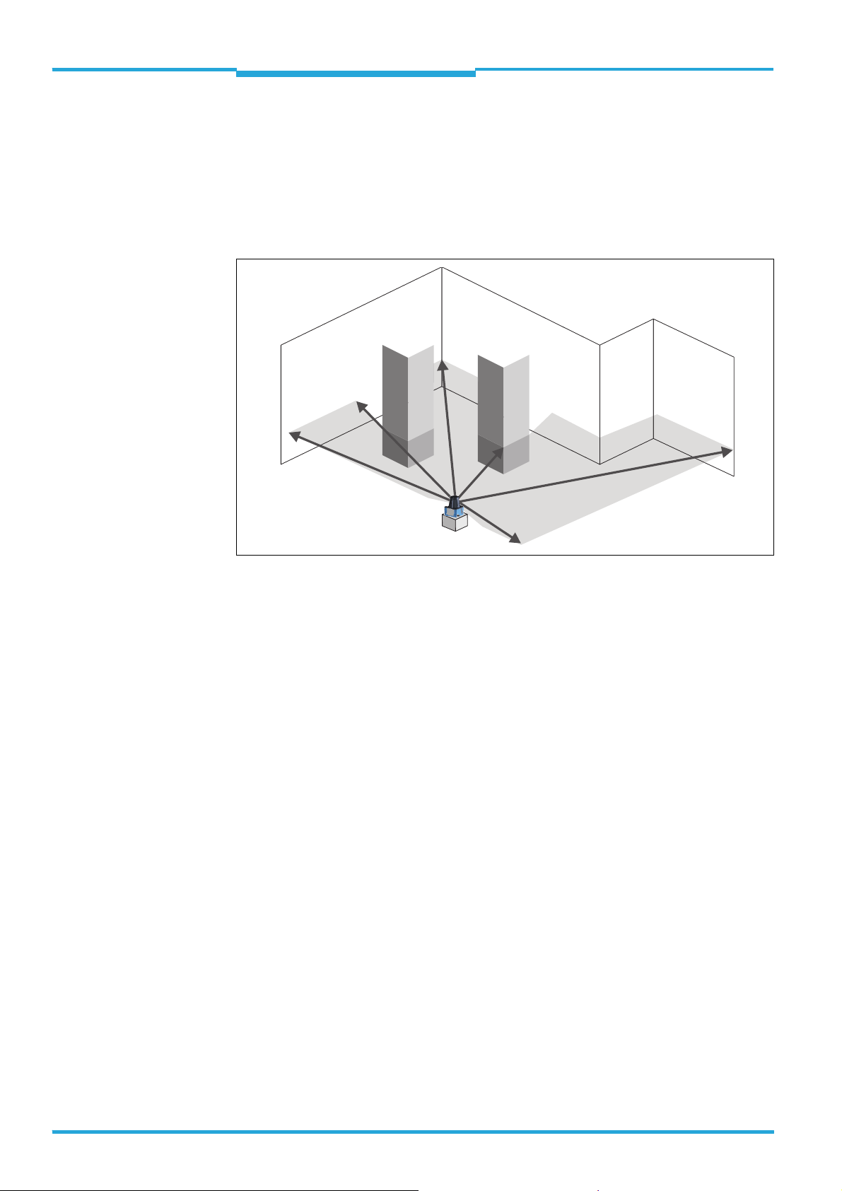
The TiM3xx is an opto-electronic laser scanner that electro-sensitively scans the perimeter
of its surroundings at a single plane with the aid of laser beams. The TiM3xx measures its
surroundings using two-dimensional polar coordinates based on its measurement origin.
This is marked on the hood in the centre using a circular indentation. If a laser beam hits
an object, its position in terms of distance and direction is determined.
Scanning is performed across a 270° sector. The maximum range of the TiM3xx is 4 m
(13.12 ft) on light, natural surfaces with an object reflectivity > 50 % (e. g. a white house
wall).
2.1 Distance measurement
The TiM3xx emits pulsed laser beams using a laser diode. If one of these laser pulses hits
an object or a person, this is reflected at its surface. The reflection is detected in the
TiM3xx's receiver by a photodiode. The TiM3xx uses HDDM technology (High Definition
Distance Measurement), a SICK own-development. Using this measurement method, a
measured value is formed by the average value for several individual pulses. The TiM3xx
calculates the distance to the object from the transit time required by the light from emission of the beam to receipt of the reflection. This principle of "time-of-flight measurement"
is used by radar systems in a similar manner.
2.2 Direction measurement
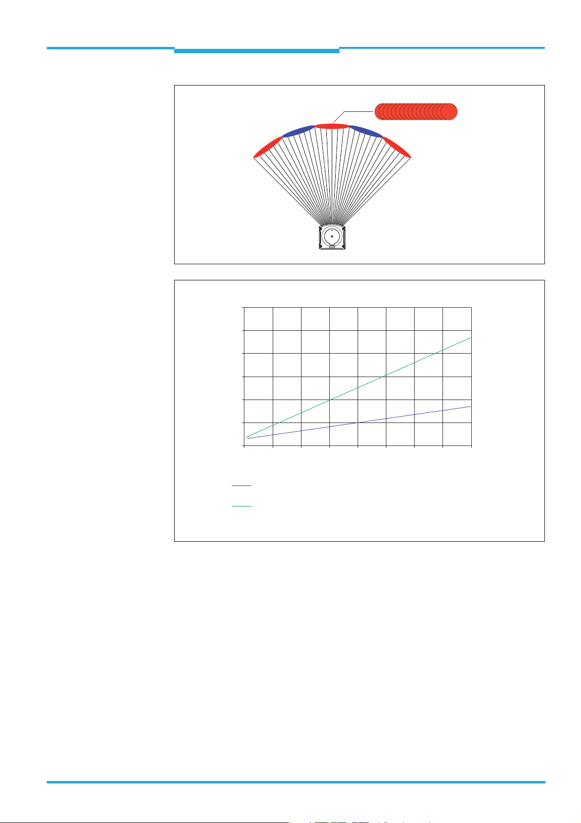
The emitted laser beams are deflected by the TiM3xx using a rotating mirror and its surroundings scanned in a circular form. The measurements are triggered internally at regular
angle increments using an angular encoder.
The TiM3xx scans at a scanning frequency of 15 Hz. The measurement method forms an
average value from several pulses to determine individual measured values.
At an angle resolution of 1°, a measuring point is formed from the average of 84 measurements. The spot geometry of the submeasuring points is virtually circular whereas a measuring point has the form of a narrow rectangle due to overlapping.
6 © SICK AG · Germany · All rights reserved · Subject to change without notice 8014318/VM03/2011-12-14
Page 7
Technical Information Chapter 2
Operating principle of the TiM3xx
TiM3xx
84 submeasuring points
TiM3xx
Spot diameter (mm/in)
120
4.73
100
3.94
80
3.15
60
2.36
40
1.58
20
0.79
0
0 0.5 1 1.5 2.5 3.5234
1.64 3.28 4.92 8.20 11.486.56 9.84 13.12
Range (m/ft)
Spot diameter of a submeasuring point.
Divergence 7 mrad, spot diameter on the front screen 6 mm (0.24 in)
Elongation of the 84 overlayed submeasuring points in direction
of deflection at angle step 1°.
Divergence 22 mrad, spot diameter on the front screen 6.5 mm (0.26 in)
8014318/VM03/2011-12-14 © SICK AG · Germany · All rights reserved · Subject to change without notice 7
Page 8
Chapter 3 Techncial Information
Mounting
TiM3xx Detecting Laser Scanner
3 Mounting
3.1 Delivery
Quantity Component Comment
1 TiM3xx laser scanner In design ordered
1 Mounting kit 1 2 straight plates, 2 x 4 mm M3 screws
1 "Manuals & Software Auto Ident“ DVD
(no. 2039442)
1 TiM3xx operating instructions Printed in English and German,
3.2 Notes on mounting
The TiM3xx can, depending on the application purpose, be mounted in any position.
Install the TiM3xx so it as unaffected by shocks and vibrations as possible.
Install the TiM3xx so it is not exposed to any direct sunlight (window, skylight) or any
other heat sources. This prevents impermissible temperature increases inside the
device.
–
available in other languages where applicable
as PDF on the DVD
Using several TiM3xx
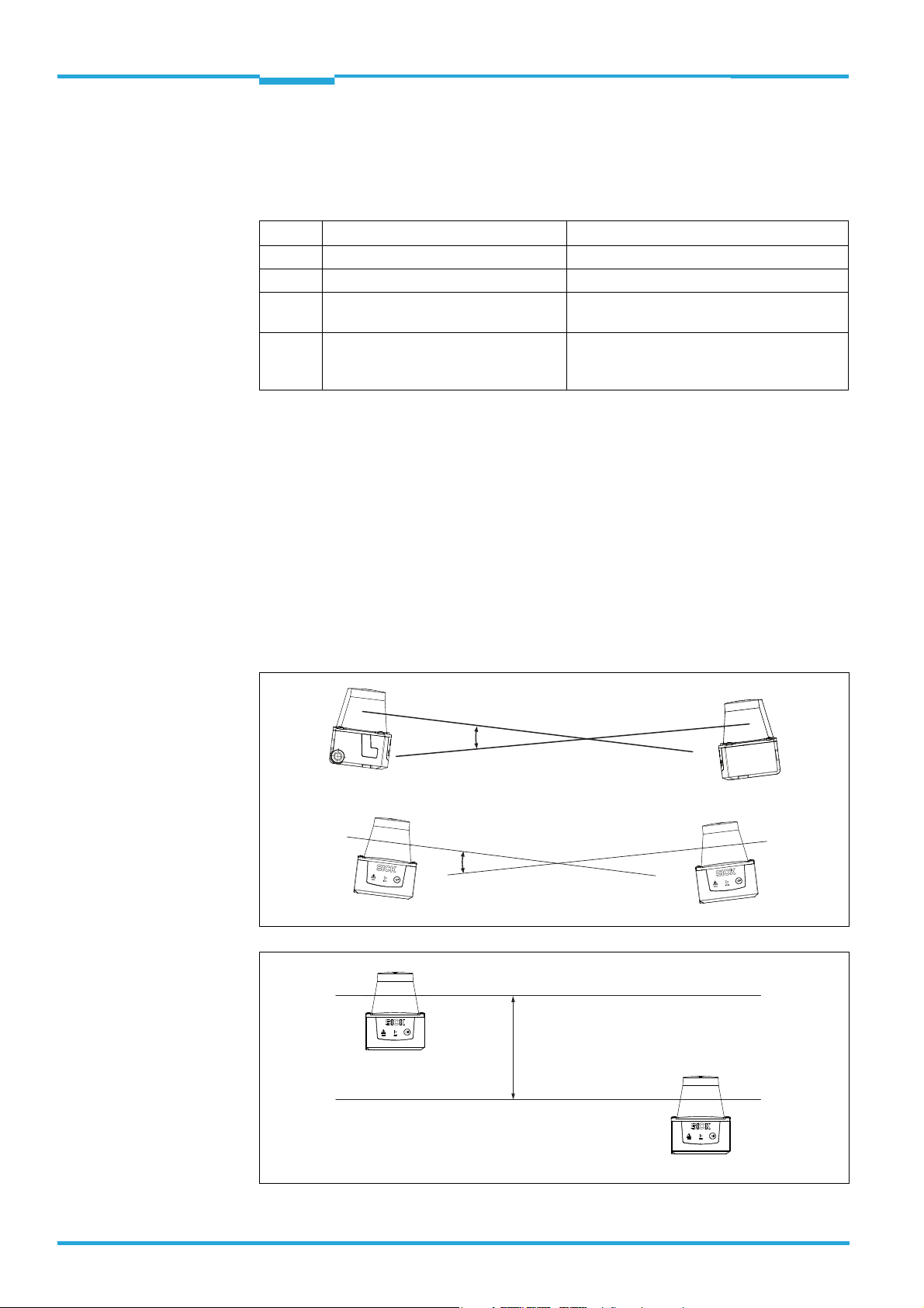
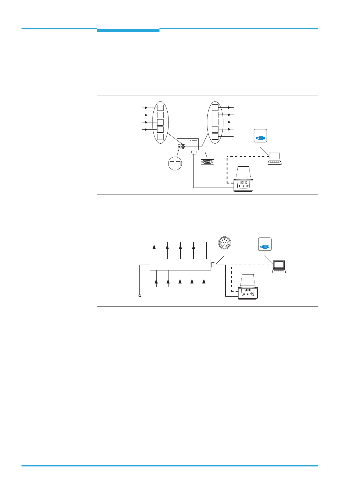
The TiM3xx is designed so that mutual interference of the same types of sensors is very unlikely. To preclude even the slightest of influences on the measuring accuracy, we recommend installing the TiM3xx as in the examples below.
Placement of two TiM3xx opposed to each other
Crosswise placement of two TiM3xx
Placement of two TiM3xx with parallel offset
8 © SICK AG · Germany · All rights reserved · Subject to change without notice 8014318/VM03/2011-12-14
Page 9
Technical Information Chapter 3
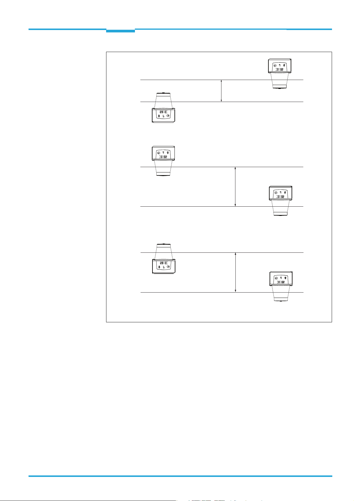
Placement of two TiM3xx with parallel offset, one of these upside down
Placement of two TiM3xx upside down, parallel offset
Placement of two TiM3xx with parallel offset, one of these upside down
TiM3xx
Mounting
8014318/VM03/2011-12-14 © SICK AG · Germany · All rights reserved · Subject to change without notice 9
Page 10
Chapter 3 Techncial Information
1
2
7
6
5
3
4
Mounting
TiM3xx Detecting Laser Scanner
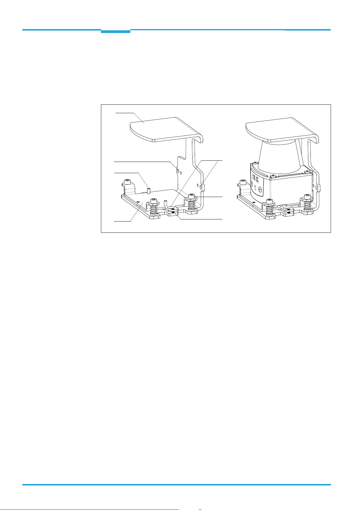
3.3 Optional accessories
3.3.1 Install mounting set 2 (part no. 2061776) on the TiM3xx
The hanger-shaped mounting set 2 is used as skirting protection and as a bracket for making fine adjustments on the scan plane. The TiM3xx can also be fastened directly onto the
bracket without the adapter plate (skirting protection only).
1 Mounting bracket
2 4.3 mm (0.17 in) diameter hole for mounting the mounting bracket horizontally or vertically on a
surface, 2 x 2
3 Cheese-head screw M4 x 16 (hexagon socket) and compression spring for aligning the TiM3xx,
3 x
4 Set screw for locking the adapter plate after alignment, 2 x
5 Adapter plate
6 Cheese-head screw M3 x 8 in a 3.2 mm (0.13 in) diameter hole for mounting the TiM3xx to the
adapter plate, 2 x
7 7.3.2 mm diameter hole for mounting the TiM3xx directly on the mounting bracket, 2 x (alterna-
tively, without option for making adjustments on the scan plane)
10 © SICK AG · Germany · All rights reserved · Subject to change without notice 8014318/VM03/2011-12-14
Page 11
Technical Information Chapter 3
Mounting
TiM3xx
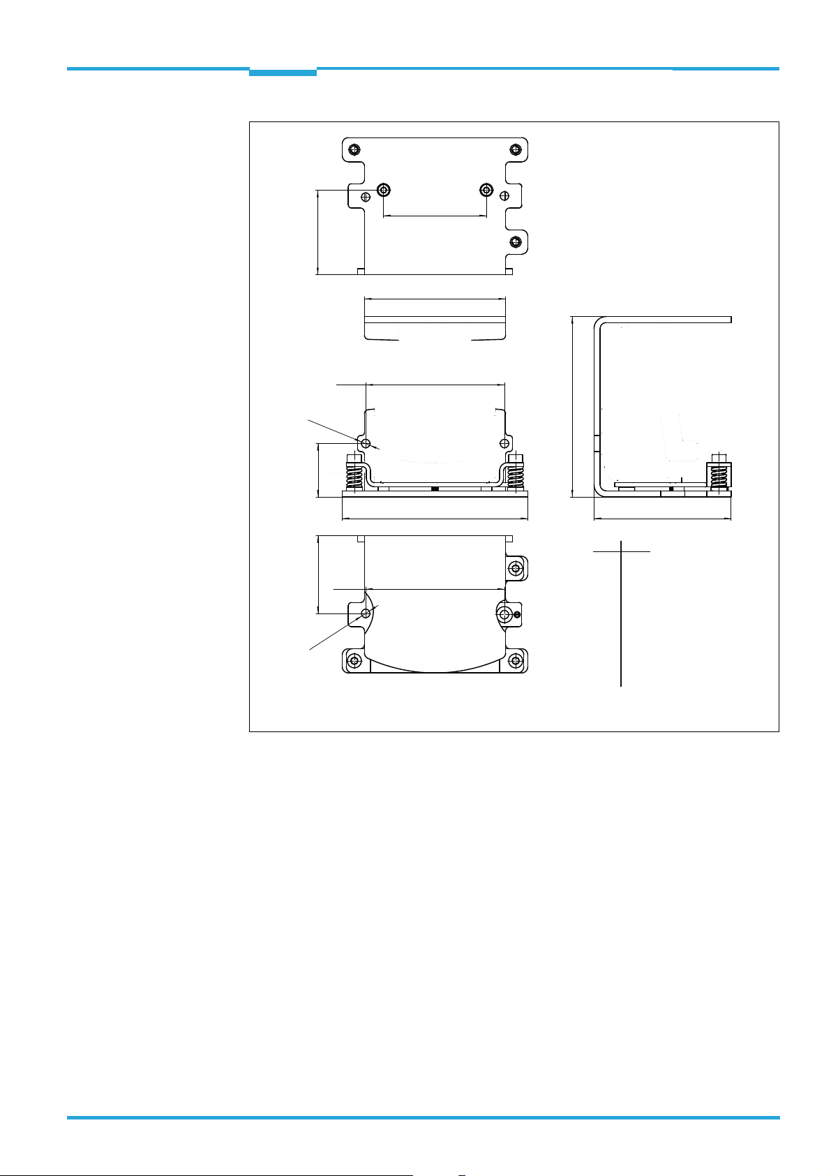
51
70
68.8
Ø 4.3 (2 x)
26.4 4238.5
92
68.8
Ø 4.3 (2 x)
89.4
mm
4.3
26.4
38.5
42.0
51.0
68.0
68.8
70.0
89.4
92.0
68
inch
0.17
1.04
1.51
1.65
2.00
2.68
2.71
2.76
3.52
3.62
All measures of length in mm
Procedure for mounting the TiM3xx
1. Mount the TiM3xx to the adapter plate using the two screws M3 x 8 supplied. For this
purpose, insert the screws from below through the hole in the mounting bracket and
the hole in the adapter plate.
2. Align the scan plane of the TiM3xx using the three cheese-head screws
3.
3. After alignment, lock the adapter plate against the mounting bracket using both set
screws
4.
8014318/VM03/2011-12-14 © SICK AG · Germany · All rights reserved · Subject to change without notice 11
Page 12
Chapter 4 Techncial Information
Electrical installation
TiM3xx Detecting Laser Scanner
4 Electrical installation
4.1 Overview of all interfaces
TiM310-1030000
IN 1
IN 2
IN 3
IN 4
SGND
TiM310-1130000
DC 10 ... 28 V
33
43
30
31
12
Connection
module
CDB730-001
...
...
1
2
OUT 1
OUT 2
OUT 3
OUT 4
GND
DC 10 ... 28 V
“Power/I/O”
customer-provided
OUT 1 OUT 2 OUT 3 OUT 4 GND
Connection box
IN 1 IN 2 IN 3 IN 4 INGND
20
21
10
13
22
“Power/I/O”
OUT 1
OUT 2
OUT 3
OUT 4
GND
“USB 2.0”
TiM3xx
“USB 2.0”
TiM3xx
USBUSB
SOPASSOPAS
Configuration
Field monitoring
Diagnosis
USBUSB
SOPASSOPAS
Configuration
Field monitoring
Diagnosis
12 © SICK AG · Germany · All rights reserved · Subject to change without notice 8014318/VM03/2011-12-14
Page 13
Technical Information Chapter 4
4
10
1112
8
6
7
9
1
5
3
2
Electrical installation
TiM3xx
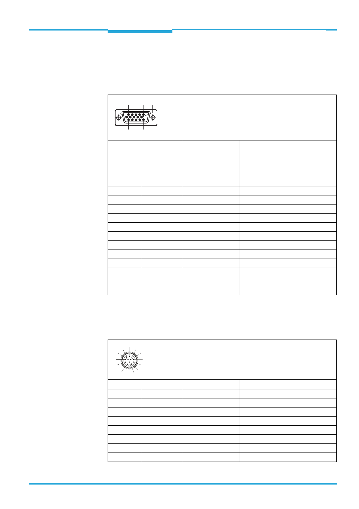
4.2 Pin and wire color assignments
4.2.1 TiM310-1030000
15-pin D-Sub HD plug on the cable
6
1
11
5
15
10
Pin Signal Color of wire Function
1 DC 10 ...28 V red Supply voltage
2n.c. purple –
3 n.c. yellow –
4 OUT 4 red + black Switching output 4 (index/error)
5GNDblack Ground
6 n.c. light blue –
7n.c. dark blue –
8 IN 1 turquoise or light gray Switching input 1 (field set selection)
9 IN 2 green Switching input 2 (field set selection)
10 IN 3 gray Switching input 3 (field set selection)
11 IN 4 pink Switching input 4 (field set selection)
12 OUT 1 brown Switching output 1 (field infringement)
13 OUT 2 orange Switching output 2 (field infringement)
14 OUT 3 white Switching output 3 (field infringement)
15 INGND white + black Common ground for all inputs
– – metal Shield
4.2.2 TiM310-1130000
12-pin M12 plug on the cable
Pin Signal Color of wire Function
1GNDblack Ground
2 DC 10 ... 28 V red Supply voltage
3 IN 1 turquoise or light gray Switching input 1 (field set selection)
4 IN 2 green Switching input 2 (field set selection)
5 OUT 1 brown Switching output 1 (field infringement)
6 OUT 2 orange Switching output 2 (field infringement)
7 OUT 3 white Switching output 3 (field infringement)
8 OUT 4 red + black Switching output 4 (index/error)
8014318/VM03/2011-12-14 © SICK AG · Germany · All rights reserved · Subject to change without notice 13
Page 14
Chapter 4 Techncial Information
Electrical installation
TiM3xx Detecting Laser Scanner
6
5
7
8
9
1
1112
4
3
2
10
Pin Signal Color of wire Function
9 INGND white + black Common ground for all inputs
10 IN 3 gray Switching input 3 (field set selection)
11 IN 4 pink Switching input 4 (field set selection)
12 n.c. – –
– – metal Shield
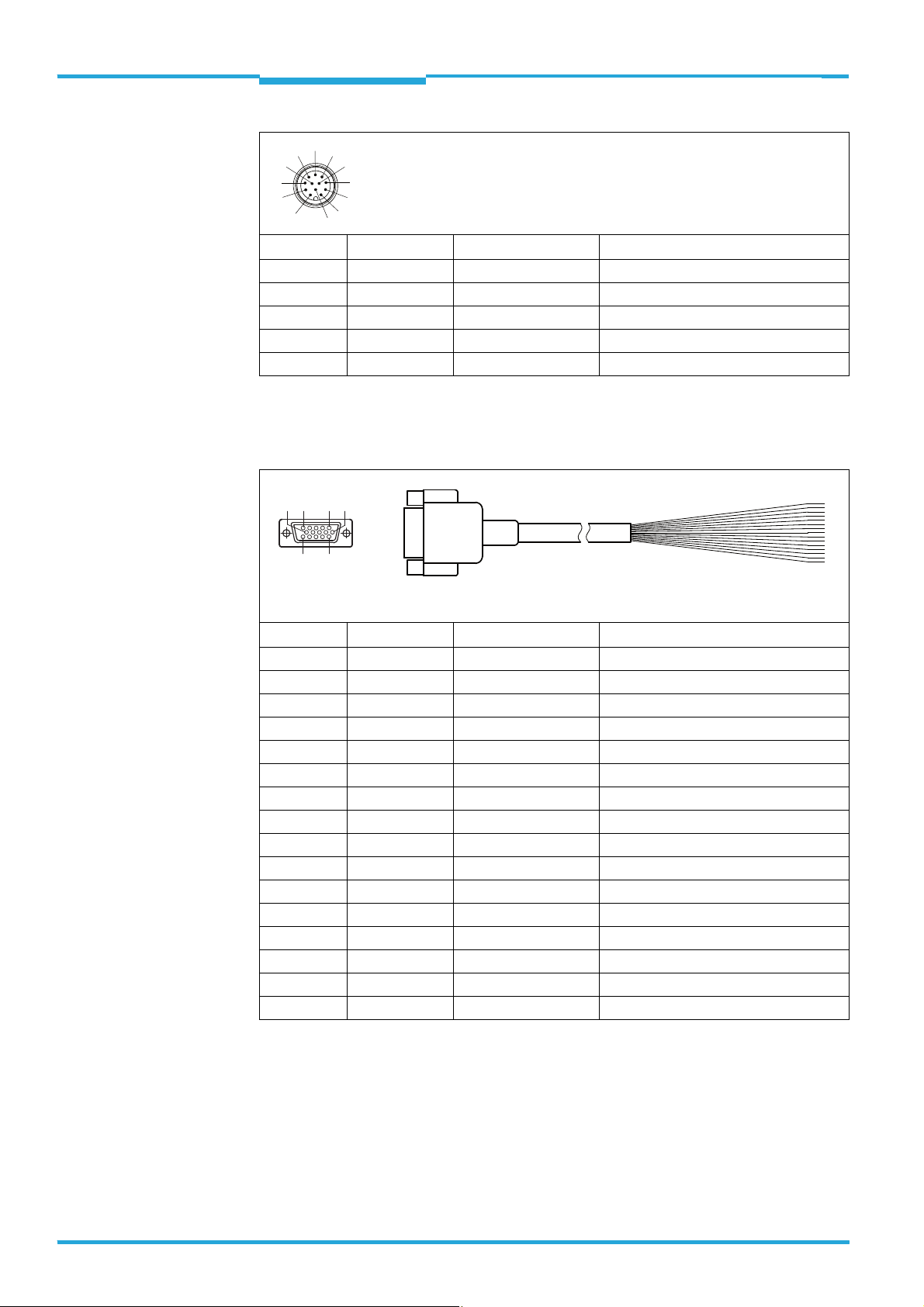
Connecting cable no. 2043413 with 15-pin D-Sub-HD socket and open end
(optional accessory)
110
5
15611
D Sub socket,
front view
Pin Signal Color of wire Function
1 DC 10 ...28 V red Supply voltage
2n.c. purple –
3 n.c. yellow –
4 OUT 4 red + black Switching output 4 (index/error)
5GNDblack Ground
6 n.c. light blue –
7n.c. dark blue –
8 IN 1 turquoise or light gray Switching input 1 (field set selection)
9 IN 2 green Switching input 2 (field set selection)
10 IN 3 gray Switching input 3 (field set selection)
11 IN 4 pink Switching input 4 (field set selection)
12 OUT 1 brown Switching output 1 (field infringement)
13 OUT 2 orange Switching output 2 (field infringement)
14 OUT 3 white Switching output 3 (field infringement)
15 INGND white + black Common ground for all inputs
– – metal Shield
14 © SICK AG · Germany · All rights reserved · Subject to change without notice 8014318/VM03/2011-12-14
Page 15

Technical Information Chapter 4
TiM3xx
Electrical installation
4.3 Notes on electrical installation
Prerequisites for enclosure rating IP 65:
The black rubber plate (USB socket) must be flush-mounted on the housing.
The TiM3xx should be protected from moisture and dust when the cover of the USB
socket is open.
Electrical connections between the TiM3xx and other devices may only be connected
or disconnected when the system is not live, otherwise the devices may be damaged.
Conducting cross sections of the supply cable from the customer's power system
should be selected and perform in accordance with the applicable standards.
If the voltage for the TiM3xx is not supplied via the optional CDB730-001 connection
module (part no. 1055981), the TiM3xx should be protected with an external 0.8 A
delay-action fuse at the start of the supply cable from the point of view of the power supply. The connection module already has a suitable fuse.
All electrical circuits connected to the TiM3xx must be designed as SELV or PELV elec-
tric circuits (SELV = Safety Extra Low Voltage, PELV = Protective Extra Low Voltage).
Do not switch on the supply voltage for the TiM3xx until the connection work has been
completed and wiring work has been checked carefully.
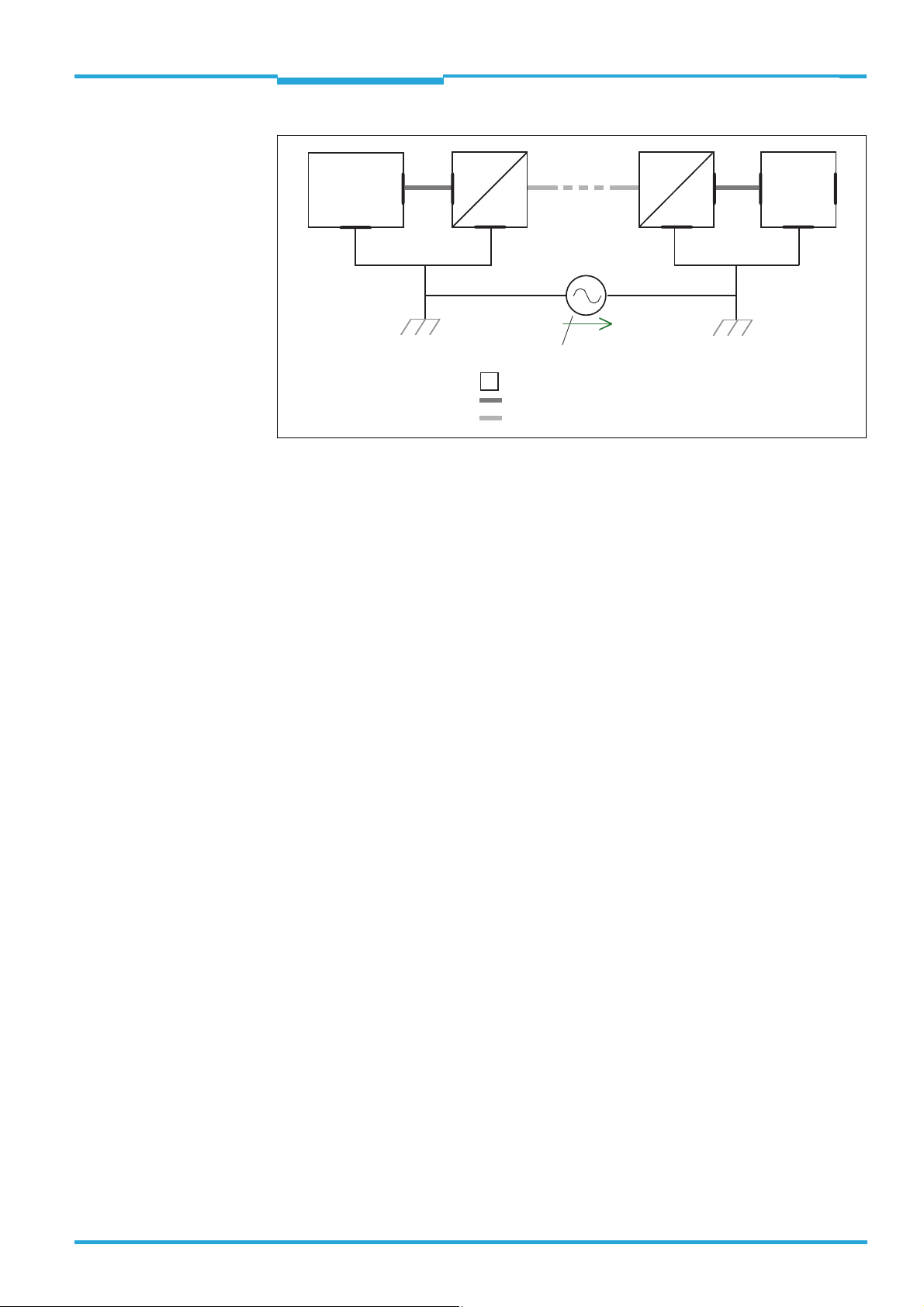
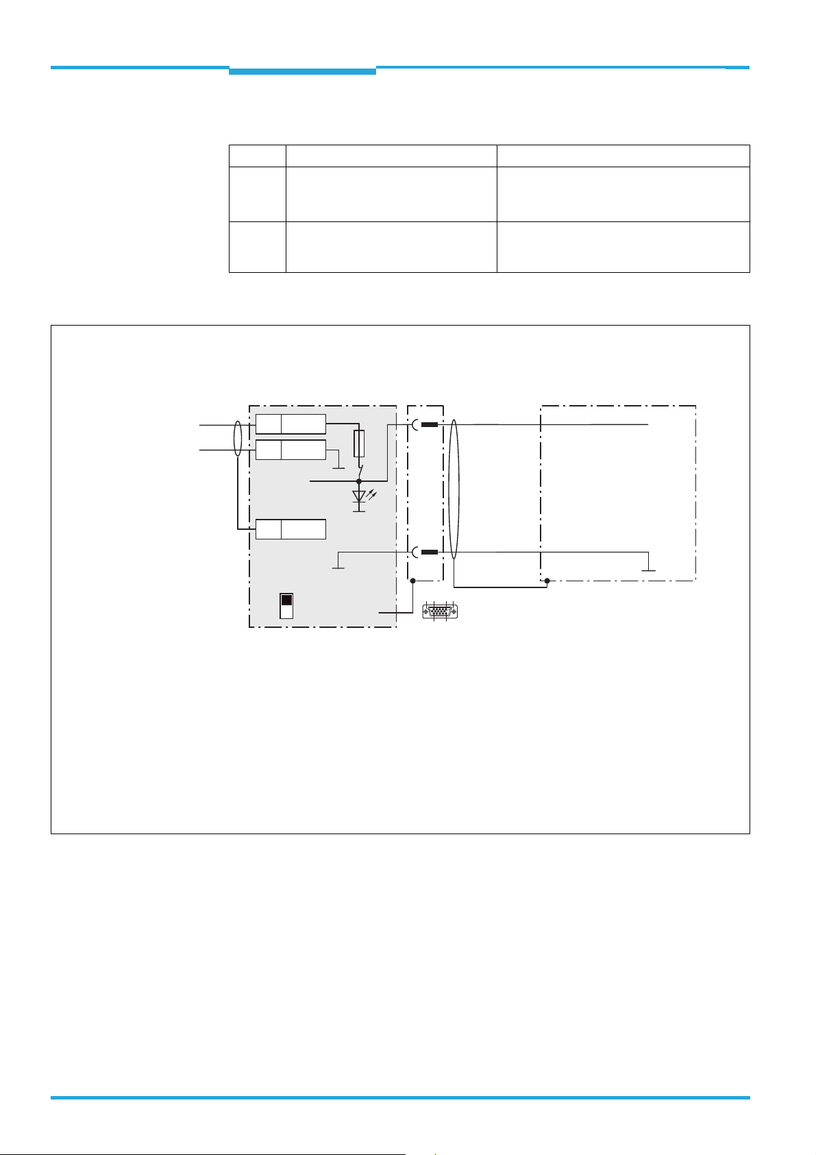
4.4 Prerequisites for safe operation of the TiM3xx in a system
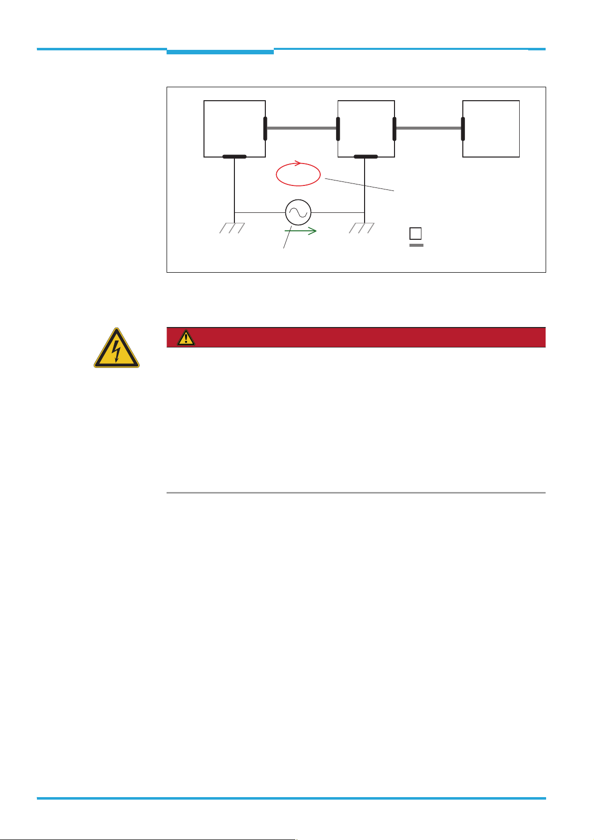
The TiM3xx is designed and tested for electrical safety according to the standard EN 609501 (2006-04)/A11 (2009-03):
It is connected to peripheral devices (power supply, control, actuators) via shielded cables.
The cable shield e.g. of the supply line is therefore flush with the metal housing of the
TiM3xx. The device can either be grounded via the cable shield or via the two straight plates.
If the peripheral devices also have metal housing and if the cable shields also flush with
their housing, it is assumed that all devices involved in installation have the same ground
potential.
This is achieved by observing the following conditions for instance:
mounting of devices on conducting metal surfaces
professional grounding of devices/metal surfaces in the system
low-impedance and current-conducting equipotential bonding between areas with dif-
ferent ground potentials if necessary.
If these conditions are not met, e.g. on devices in a widely distributed system across several
buildings, equipotential bonding currents may, due to different ground potentials, flow via
the cable shields between the devices, which can lead to dangers.
8014318/VM03/2011-12-14 © SICK AG · Germany · All rights reserved · Subject to change without notice 15
Page 16
Chapter 4 Techncial Information
DANGER
Electrical installation
Trigger for
switching inputs
Actuators for
switching outputs
TiM3xx
TiM3xx Detecting Laser Scanner
Power
supply unit
grounding point 1
grounding potential difference
I
U
grounding point 2
closed current loop
with equalizing currents
via cable shields
= metal housing
= shielded electrical cable
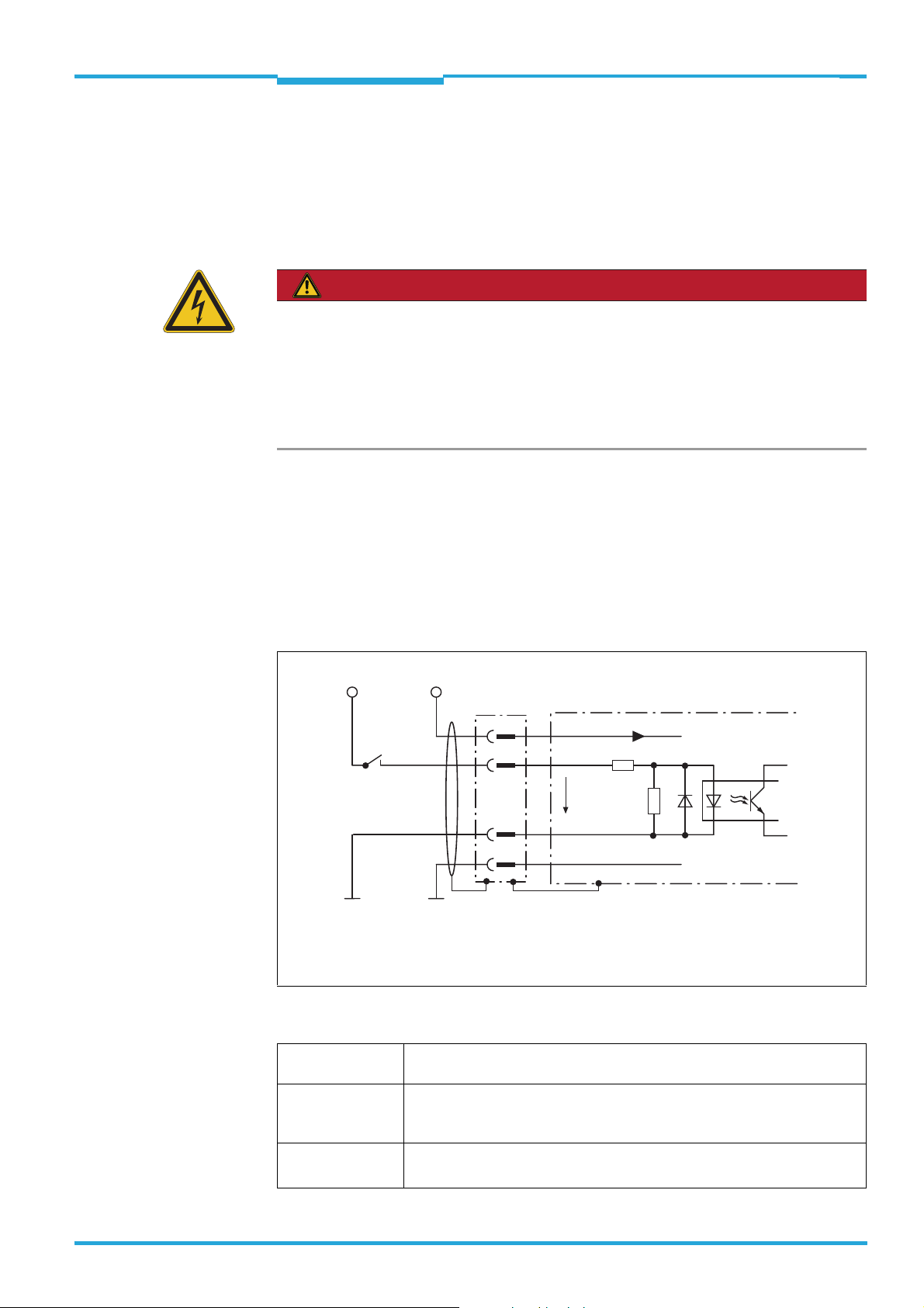
Insufficient ground potential equalization leads to voltage differences arising between
grounding points 1 and 2. The current loop closes via the shielded cables/metal housing.
Risk of injury/risk of damage due to electrical current!
Equipotential bonding currents between the TiM3xx and other grounded devices in the system may have the following effects:
dangerous currents on the metal housing e.g. of the TiM3xx
incorrect functioning or irreparable damage to the devices
Damage/irreparable damage of the cable shield due to heating and cable fires
Where local conditions are unfavorable and thus do not meet conditions for a safe
earthing method (same ground potential at all grounding points), carry out the measures below.
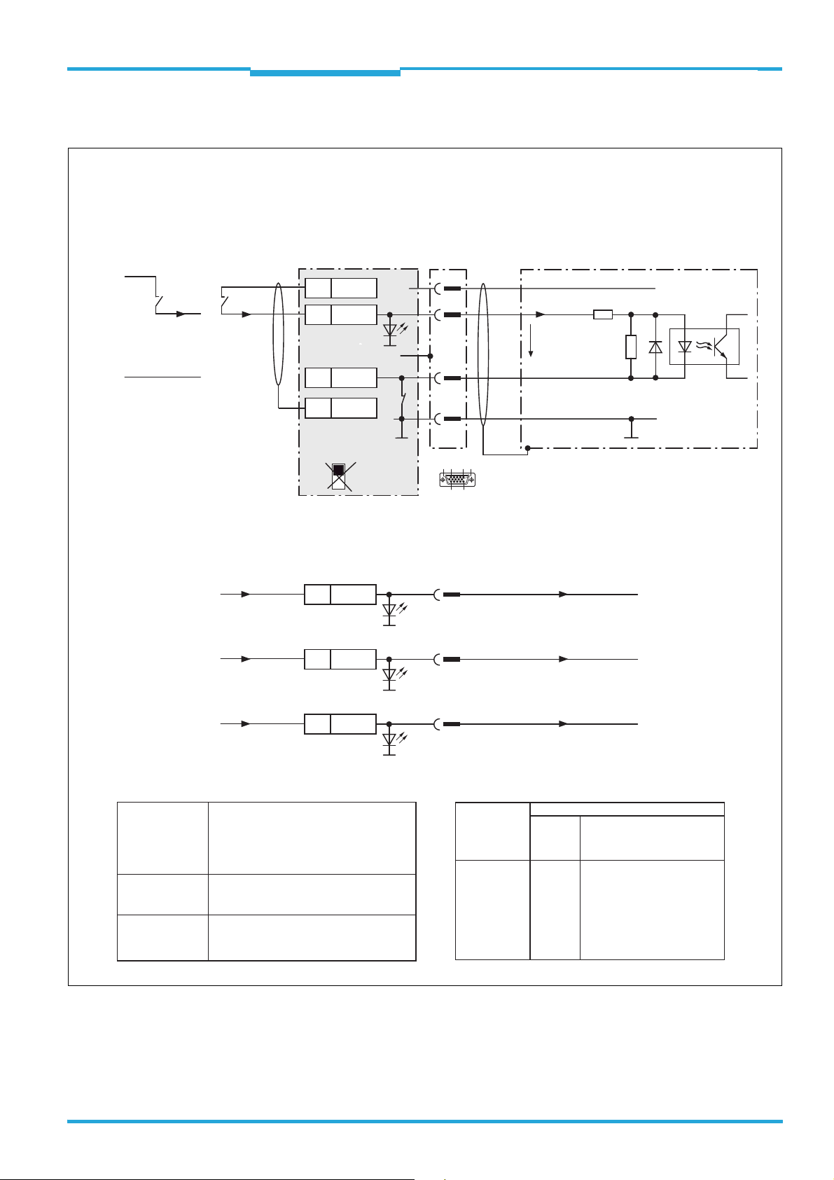
Remedial measures
The primary solution for avoiding equipotential bonding currents on the cable shields is to
guarantee low-impedance and current-conducting potential equalization. If this is not possible, the following two solution approaches are intended as suggestions.
Important It is not advisable to open up the cable shields. This can cause compliance with EMC limit
values for the devices to be no longer guaranteed.
a) Measures for widely distributed system installations
On widely distributed system installations with correspondingly large potential differences,
we recommend setting up local islands and connecting them using commercially available
electro-optical signal isolators . This will attain maximum resistance to electromagnetic interference, while observing all requirements of EN 60950-1 at the same time.
16 © SICK AG · Germany · All rights reserved · Subject to change without notice 8014318/VM03/2011-12-14
Page 17
Technical Information Chapter 4
Electrical installation
TiM3xx
Trigger for
switching inputs
Actuators for
switching outputs
Electro-
optical
signal
isolators
Electro-
optical
signal
isolators
TiM3xx
U
grounding point 1
grounding potential difference
= metal housing
= shielded electrical cable
= fiber optic cable
grounding point 2
The ground loop is isolated by using the electro-optical signal isolator between the islands.
Equalization currents are prevented on the cable shields within the islands by conductible
equipotential bonding.
8014318/VM03/2011-12-14 © SICK AG · Germany · All rights reserved · Subject to change without notice 17
Page 18

Chapter 4 Techncial Information
Trigger for
switching inputs
Actuators for
switching outputs
TiM3xx
grounding point 2 grounding point 3
grounding point 1
Power
supply unit
= metal housing
= shielded electrical cable
electrically
insulated
U
grounding potential difference
Electrical installation
TiM3xx Detecting Laser Scanner
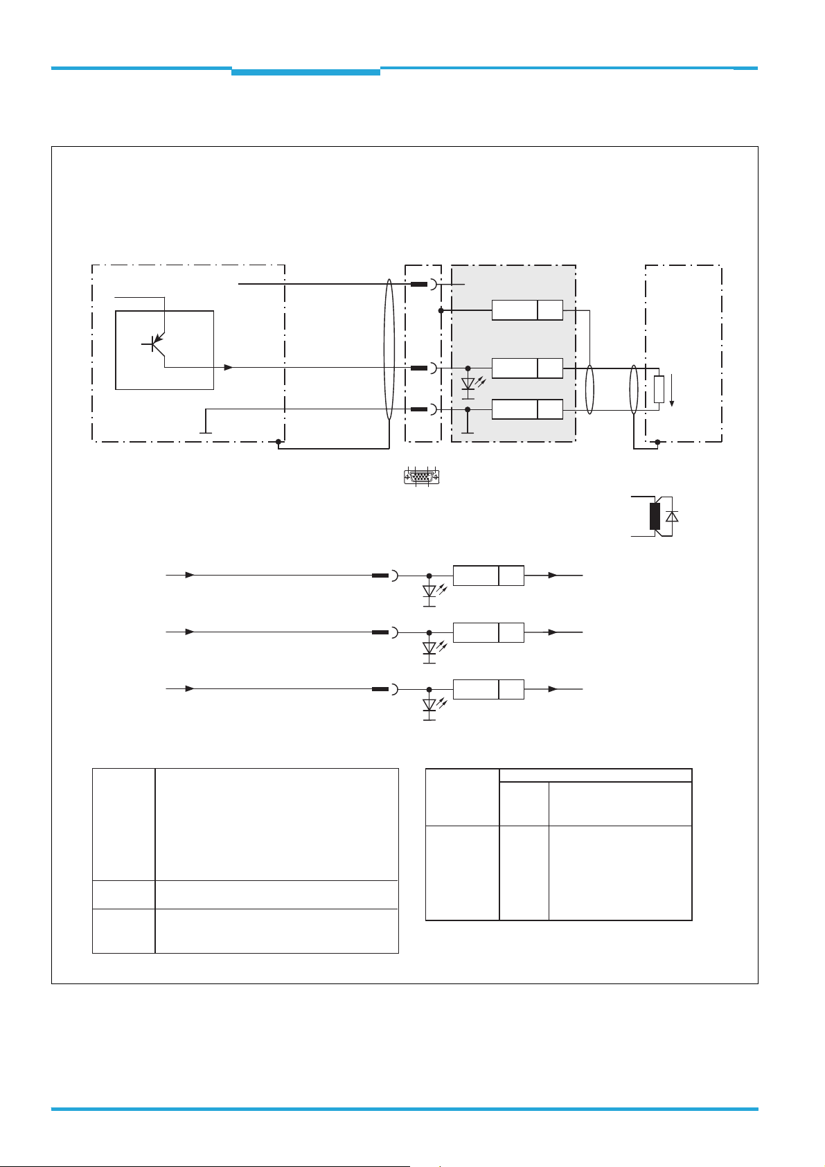
b) Measures for small system installations
For smaller installations with only slight potential differences, insulated installation of the
TiM3xx and of peripheral devices may be a sufficient solution.
Ground loops are, even in the event of large differences in ground potential, effectively prevented. This prevents any equalization currents flowing via the cable shields or metal housings.
Important The power supply for the TiM3xx and the connected peripheral devices must also guarantee
the required level of insulation.
Under certain circumstances, a tangible potential can develop between the insulated metal
housings and the local ground potential.
Special national regulations for Sweden and Norway
Varning och atjarder
Utrustning som ar kopplad till skyddsjord via jordat vagguttag och/eller via annan utrustning
och samtidigt ar kopplad till kabel-TV nat kan i vissa fall medfora risk for brand.
For att undvika detta skall vid anslutning av utrustningen till kabel-TV nat galvanisk iso-
lator finnas mellan utrustningen och kabel-TV natet.
Advarsel og tiltaker
Utstyr som er koplet til beskyttelsesjord via nettplugg og/eller via annet jordtilkoplet utstyr
- og er tilkoplet et kabel - TV nett, kan forarsake brannfare.
For a unnga dette skal det ved tilkopling av utstyret til kabel-TV nettet installeres en gal-
vanisk isolator mellom utstyret og kabel-TV nettet.
18 © SICK AG · Germany · All rights reserved · Subject to change without notice 8014318/VM03/2011-12-14
Corresponding English translation
Devices which are connected to the electrical system PE of the building via a mains connection or other devices with a connection to the PE, and which are connected to a cable distribution system with coaxial cables, can under certain circumstances cause a risk of fire.
Connections to a cable distribution system must therefore be made such that electrical
insulation is offered below a certain frequency range (galvanic separating link).
Page 19
Technical Information Chapter 4
DANGER
TiM3xx
Electrical installation
4.5 Installation steps
4.5.1 Supply voltage connection
The TiM3xx requires a supply voltage between DC 10 and 28 V (stabilized protective extralow voltage) (SELV or PELV) as per the IEC 60364-4-41 standard (VDE 0100 part 410)).
The electricity source must be able to provide a power of 5 W at minimum.
Risk of injury due to electrical current!
If the supply voltage is generated by extracting and converting current from the alternating
current network using a stabilized power supply unit, insufficient electrical separation
between the input and output circuit may lead to an electric shock.
Only use a power supply unit whose output circuit has reliable electrical separation due
to double insulation and a safety transformer as per IEC 742 (VDE 0551).
4.5.2 Wiring of switching inputs IN 1 to IN 4
The four digital switching inputs activate one of the of the 16 field sets in binary combination
as an evaluation case (combinatorics table see TiM3xx operating instructions). The inputs
are decoupled from the supply voltage of the TiM3xx. They have a common supply point
however (IN GND) and are therefore not mutually decoupled.
Important If the TiM3xx is operated together with a CDB730-001 connection module, ensure the IN-
GND supply point is permanently wired with the GND of the TiM3xx.
V
S ext
GND
Structure and wiring principle of input IN 2 (pin 9),
IN 3 (pin 10) and IN 4 (pin 11) same as input IN 1.
V
S
GND
1
8
15
5
TiM3xx
V
S
6.64 K
IN 1
V
in
3.32 K
INGND
GND
Vin = max. 32 V
V
S
GND
= DC 10 ... 28 V
V
S
Characteristic data of all switching inputs is identical.
Switching behavior Current at the input starts the allocated function in the TiM3xx.
(default setting: level: active high; debouncing: 10 ms)
Properties –Opto-decoupled
– Can be switched with an electronic switch (PNP output) or a mechanical
switch
Electrical values Low: V
High: 8 VV
8014318/VM03/2011-12-14 © SICK AG · Germany · All rights reserved · Subject to change without notice 19
2 V; Iin 0.3 mA
in
32 V; 0.7 mA Iin 5 mA
in
Page 20
Chapter 4 Techncial Information
Electrical installation
TiM3xx Detecting Laser Scanner
4.5.3 Wiring of switching outputs OUT 1 to OUT 4
Switching outputs OUT 1 to OUT 3 signal in combination infringement of the individual fields
of a field set (combinatorics table see TiM3xx operating instructions ). Output OUT 4 is used
to output an error and a regular index pulse.
TiM3xx
For inductive load:
OUT 1
GND
= DC 10 ... 28 V
V
S
Structure and wiring principle of output
OUT 2 (pin 13), OUT 3 (pin 14) and
OUT 4 (pin 4) same as output OUT 1
12
V
5
out
Characteristic data of all switching outputs is identical.
Switching behavior PNP-switching against supply voltage VS.
OUT 1 to OUT 3:
Idle level: High (no field infringement),
Working level: Low (field infringement)
Response time: 134 ms to 30 s (adjustable via SOPAS-ET)
Duration time: 0 ms to 10 s (adjustable via SOPAS-ET)
OUT 4:
Idle level: High (Device Ready),
Working level: Low (error), low pulse (15 Hz, index, corresponds to measurement at 90°)
Properties – Short-circuit resistant and temperature-protected
– Not electrically isolated from the supply voltage V
Electrical values 0 V V
Guaranteed: (VS – 1.5 V)V
out
V
S
VS at I
out
100 mA
out
Quenching circuit:
Install an anti-surge
diode directly at the
load!
S
Important Longer connecting cables at the switching outputs of the TiM3xx should be avoided due to
the resultant voltage drop. This is calculated as follows:
2 x length x current
V = --------------------------------------
Conductance value x cross section
Conductance value for copper: 56 m/ mm
2
.
20 © SICK AG · Germany · All rights reserved · Subject to change without notice 8014318/VM03/2011-12-14
Page 21
Technical Information Chapter 4
Electrical installation
TiM3xx
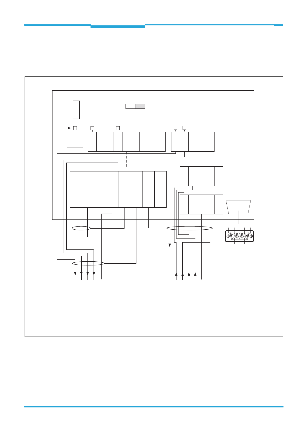
4.6 Use of the CDB730-001 connection module
(part no. 1055981)
4.6.1 Wiring overview
CDB730-001 connection module
LEDs
SGND - GND
SGND
GND
S3
OUT 4
Shield
*
IN
U
F
0.8 A T
S1
POWER
1234567 8
10 11 12 13 14 15 16 17 18
ONOFF
IN
U
OUT 3
GND
*
IN
U
IN
U
ONOFF
SGND
Shield
*)
nc
nc
Shield
DC 10 ... 28 V
20 21 22 23 24
OUT 1
SGND
OUT 2
30 31 32 33 34
IN 3
Shield
40 41 42 43 44
nc
GND
IN 4
nc
nc
GND
GND
nc
IN 1
IN 2
nc
SCANNER
nc
6110 5
1115
to
TiM3xx
U
IN*
OUT 1 2 3 4 GND IN 1 2 3 4 GND
Output
field infringement/error
Triggeri ng
switching inputs
VS = DC 10 ... 28 V on terminal UIN = UIN* after fuse F and switch S1
*) SGND of “IN 1 ... IN 4” switching inputs switched to GND of TiM3xx. Not changeable!
Do not wire terminals marked with “nc” (not connected)!
8014318/VM03/2011-12-14 © SICK AG · Germany · All rights reserved · Subject to change without notice 21
Page 22
Chapter 4 Techncial Information
Electrical installation
TiM3xx Detecting Laser Scanner
4.6.2 Switch
Switch Function Default
S1 Supply voltage present:
ON: Supply voltage U
OFF: Supply voltage U
IN*
IN*
S3 Supply potential for SGND:
on
off
ON
ON (not changeable)
ON: connected with GND of the
TiM3xx
4.6.3 Connecting the supply voltage in the CDB730-001
Wiring the power supply voltage in the CDB730-001 connection module
DC 10 ... 28 V
CDB730-001
1U
IN
2 GND
UIN*
5
Shield
S1 : POWER
ON
OFF
POWER
Shield
UIN*
F
S1
GND
1
.
.
.
5
10
6
5
1
15
11
D Sub HD
plug, 15-pin
.
.
.
V
S
GND
Vs = DC 10 ... 28 V on terminal UIN = UIN* after fuse F and switch S1
Switch S1:
ON:
Power supply voltage U
Power supply voltage U
OFF:
CDB730-001 and TiM3xx disconnected from power supply voltage.
Recommended position during all electrical installation work.
switched to UIN* via fuse to CDB730-001 and TiM3xx.
IN
* additionally available on terminals 11 and 14.
IN
TiM3xx
VS
22 © SICK AG · Germany · All rights reserved · Subject to change without notice 8014318/VM03/2011-12-14
Page 23
Technical Information Chapter 4
Electrical installation
TiM3xx
4.6.4 Wiring the switching inputs in the CDB730-001
Wiring the “IN 1 ... IN 4” switching inputs of the TiM3xx in the CDB730-001 connection module
Scheme:
Control element
supplied externally
V
S ext
GND
Control element
supplied via
CDB730-001
11
33
U
IN
IN 1
UIN*
*
Shield
12
SGND
6
Shield
S3
GND
S3 : SGND-GND
ON
OFF
*)
UIN* = DC 10 ... 28 V
1
8
15
5
10
6
5
1
15
11
D Sub HD
plug, 15-pin
TiM3xxCDB730-001
V
S
VS
IN 1
.
V
.
in
.
6.64 K
3.32 K
INGND
GND
GND
Vin = max. 32 V
*) INGND of the “IN 1 ... IN 4” switching inputs switched to GND of TiM3xx. Not changeable!
43
30
31
Ratings for “IN 1 ... IN 4” switching inputs
Switching
behavior
Features
Electrical
values
Power fed to an input in combination with
the other inputs starts the assigned field
set as evaluation case.
Default settings: active high level,
debouncing 10 ms
– Reverse polarity protected
– Can be wired with the PNP output of a
sensor or with a mechanical switch
Low: V
High: 8 V ≤ V
0.7 mA ≤ I
≤ 2 V; Iin ≤ 0.3 mA
in
≤ 32 V;
in
≤ 5 mA
in
IN 2
IN 3
IN 4
9
10
11
IN 2
IN 3
IN 4
Pin and wire color assignment of prefabricated cables
Signal
V
S
IN 1
IN 2
IN 3
IN 4
GND
Cable no. 2043413
D Sub HD
socket,
Open end,
15 cores
15-pin
1
8
9
10
11
5
Red
Turquoise or light blue
Green
Gray
Pink
Black
8014318/VM03/2011-12-14 © SICK AG · Germany · All rights reserved · Subject to change without notice 23
Page 24
Chapter 4 Techncial Information
Electrical installation
TiM3xx Detecting Laser Scanner
4.6.5 Wiring the switching outputs in the CDB730-001
Wiring the “OUT 1 ... OUT 4” switching outputs of the TiM3xx in the CDB730-001 connection module
Scheme:
TiM3xx
OUT 2
OUT 3
CDB730-001
S
1
UIN*V
Load (e.g. PLC)
5Shield
OUT 1
GND
12
5
10
6
5
1
15
11
D Sub HD
plug, 15-pin
GND
GND
* = DC 10 ... 28 V
U
IN
20OUT 1
22
V
out
For inductive load:
Quenching circuit:
13
21OUT 2
Install an anti-surge
diode directly at the
load!
14
10OUT 3
OUT 4
Ratings for “OUT 1 ... OUT 4” switching outputs
Switching
behavior
Features
Electrical
values
PNP switching against the supply voltage V
– OUT 1 ... OUT 3:
Idle level: High (no field infringement)
Working level: Low (field infringement)
– OUT 4:
Idle level: High (Device Ready)
Working level: Low (error), Low (15 Hz, Index,
corresponds to measurement at 90°)
– Short-circuit proof + temperature protected
– Galvanically not separate from V
0 V ≤ V
≤ V
out
Guaranteed:
(V
−1.5 V) ≤ V
S
S
out
≤ VS at I
out
S
≤ 100 mA
4
13OUT 4
Pin and wire color assignment of prefabricated cables
S
Signal
V
S
OUT 1
OUT 2
OUT 3
OUT 4
GND
Cable no. 2043413
D Sub HD
socket,
Open end,
15 cores
15-pin
1
12
13
14
4
5
Red
Brown
Orange
White
Red + black
Black
24 © SICK AG · Germany · All rights reserved · Subject to change without notice 8014318/VM03/2011-12-14
Page 25

Technical Information Chapter 5
TiM3xx
License texts
5 License texts
In the product TiM3xx, SICK uses unmodified open source software and, as far as required
and permitted in accordance with the relevant license conditions, modified open source
software.
5.1 List of software licenses
1. NCURSES - 5.7- License:
Copyright (c) 2006 Free Software Foundation, Inc.
2. Z-Lib 1.2.3:
Copyright (C) 1995-2004 Jean-loup Gailly and Mark Adler
3. e2fsprogs-1.41.11 (UUID-license based on BSD 3-clause license):
Copyright (C) 1996, 1997 Theodore Ts'o.
4. Dropbear - 0.52.tar.bz2:
Copyright (c) 2002-2008 Matt Johnston - Portions copyright (c) 2004 Mihnea Stoenescu
5.1 Import code in keyimport.c is modified from PuTTY's import.c, licensed as follows:
PuTTY is copyright 1997-2003 Simon Tatham - Portions copyright Robert de Bath, Joris
van Rantwijk, Delian Delchev, Andreas Schultz, Jeroen Massar, Wez Furlong, Nicolas
Barry, Justin Bradford, and CORE SDI S.A.
5. OpenSSH - 5.1p1
5.1 Cryptographic attack detector for ssh - source code: Copyright (c) 1998 CORE SDI
S.A., Buenos Aires, Argentina.
5.2 Copyright 1995, 1996 by David Mazieres <dm@lcs.mit.edu>.
5.3 Copyright (c) 1983, 1990, 1992, 1993, 1995 The Regents of the University of California.
5.4 Remaining components of the software are provided under a standard 2-term BSD licence with the following names as copyright holders: Markus Friedl, Theo de Raadt,
Niels Provos, Dug Song, Aaron Campbell, Damien Miller, Kevin Steves, Daniel Kouril,
Wesley Griffin, Per Allansson, Nils Nordman, Simon Wilkinson
Portable OpenSSH additionally includes code from the following copyright holders, also
under the 2-term BSD license: Ben Lindstrom, Tim Rice, Andre Lucas, Chris Adams,
Corinna Vinschen, Cray Inc., Denis Parker , Gert Doering, Jakob Schlyter, Jason Downs,
Juha Yrjölä, Michael Stone, Networks Associates Technology, Inc., Solar Designer, Todd
C. Miller, Wayne Schroeder, William Jones, Darren Tucker, Sun Microsystems, The SCO
Group, Daniel Walsh
5.5 Portable OpenSSH contains the following additional licenses:
a) snprintf replacement: Copyright Patrick Powell 1995
b) Compatibility code (openbsd-compat): Some code is licensed under a 3-term BSD license, to the following copyright holders: Todd C. Miller, Theo de Raadt, Damien Miller,
Eric P. Allma, The Regents of the University of California, Constantin S. Svintsoff
c) Some code is licensed under an ISC-style license, to the following copyright holders:
Internet Software Consortium: Todd C. Miller, Reyk Floeter, Chad Mynhier
d) Some code is licensed under a MIT-style license to the following copyright holders:
Free Software Foundation, Inc.
6. GNU GENERAL PUBLIC LICENSE (Version 2, June 1991):
Copyright (C) 1989, 1991 Free Software Foundation, Inc., 51 Franklin Street, Fifth
Floor, Boston, MA 02110-1301 USA
8014318/VM03/2011-12-14 © SICK AG · Germany · All rights reserved · Subject to change without notice 25
Page 26

Chapter 5 Techncial Information
License texts
TiM3xx Detecting Laser Scanner
6.1 BusyBox 1.16.1: Copyright (C) 1989, 1991 Free Software Foundation, Inc., 51 Franklin
Street, Fifth Floor, Boston, MA 02110-1301 USA
6.2 iproute2-2.6.34: Copyright (C) 1989, 1991 Free Software Foundation, Inc., 51 Franklin
Street, Fifth Floor, Boston, MA 02110-1301 USA
6.3 kexec-tools-2.0.1: Copyright (C) 1989, 1991 Free Software Foundation, Inc., 51 Franklin Street, Fifth Floor, Boston, MA 02110-1301 USA
6.4 libelf-0.8.12.: Copyright (C) 1989, 1991 Free Software Foundation, Inc., 51 Franklin
Street, Fifth Floor, Boston, MA 02110-1301 USA
6.5 libgcc: Copyright (C) 1989, 1991 Free Software Foundation, Inc., 51 Franklin Street,
Fifth Floor, Boston, MA 02110-1301 USA
6.6 ltrace-0.5: Copyright (C) 1989, 1991 Free Software Foundation, Inc., 51 Franklin
Street, Fifth Floor, Boston, MA 02110-1301 USA
6.7 lzo-2.03: Copyright (C) 1989, 1991 Free Software Foundation, Inc., 51 Franklin Street,
Fifth Floor, Boston, MA 02110-1301 USA
6.8 mtd-utils-1.3.1: Copyright (C) 1989, 1991 Free Software Foundation, Inc., 51 Franklin
Street, Fifth Floor, Boston, MA 02110-1301 USA
6.9 porcps-3.2.8 (only ps used): Copyright (C) 1989, 1991 Free Software Foundation, Inc.,
51 Franklin Street, Fifth Floor, Boston, MA 02110-1301 USA
6.10udev-119: Copyright (C) 1989, 1991 Free Software Foundation, Inc., 51 Franklin
Street, Fifth Floor, Boston, MA 02110-1301 USA
7. libstdc++:
GNU LESSER GENERAL PUBLIC LICENSE (Version 3, 29 June 2007): Copyright (C) 2007
Free Software Foundation, Inc. <http://fsf.org/>
8. Glibc 2.8
8.1 GNU LESSER GENERAL PUBLIC LICENSE (Version 3, 29 June 2007): Copyright (C) 2007
Free Software Foundation, Inc. <http://fsf.org/>
8.2 GNU GENERAL PUBLIC LICENSE (Version 3, 29 June 2007): Copyright © 2007 Free
Software Foundation, Inc. <http://fsf.org/>
5.2 Used open source software and corresponding license
texts
1. NCURSES - 5.7 - License
Copyright (c) 2006 Free Software Foundation, Inc.
Permission is hereby granted, free of charge, to any person obtaining a copy of this software
and associated documentation files (the "Software"), to deal in the Software without restriction, including without limitation the rights to use, copy, modify, merge, publish, distribute,
distribute with modifications, sublicense, and/or sell copies of the Software, and to permit
persons to whom the Software is furnished to do so, subject to the following conditions:
The above copyright notice and this permission notice shall be included in all copies or substantial portions of the Software.
THE SOFTWARE IS PROVIDED "AS IS", WITHOUT WARRANTY OF ANY KIND, EXPRESS OR IMPLIED, INCLUDING BUT NOT LIMITED TO THE WARRANTIES OF MERCHANTABILITY, FITNESS
FOR A PARTICULAR PURPOSE AND NONINFRINGEMENT. IN NO EVENT SHALL THE ABOVE
COPYRIGHT HOLDERS BE LIABLE FOR ANY CLAIM, DAMAGES OR OTHER LIABILITY, WHETHER IN AN ACTION OF CONTRACT, TORT OR OTHERWISE, ARISING FROM, OUT OF OR IN CONNECTION WITH THE SOFTWARE OR THE USE OR OTHER DEALINGS IN THE SOFTWARE.
26 © SICK AG · Germany · All rights reserved · Subject to change without notice 8014318/VM03/2011-12-14
Page 27

Technical Information Chapter 5
TiM3xx
License texts
Except as contained in this notice, the name(s) of the above copyright holders shall not be
used in advertising or otherwise to promote the sale, use or other dealings in this Software
without prior written authorization.
These are the principal authors/contributors of ncurses since 1.9.9e, in decreasing order
of their contribution:
TD Thomas E. Dickey
JPF Juergen Pfeifer
ESR Eric S Raymond
AVL Alexander V Lukyanov
PB Philippe Blain
SV Sven Verdoolaege
2. Z-Lib 1.2.3
Copyright (C) 1995-2004 Jean-loup Gailly and Mark Adler
This software is provided 'as-is', without any express or implied warranty. In no event will the
authors be held liable for any damages arising from the use of this software.
3. e2fsprogs-1.41.11 (UUID-license based on BSD 3-clause license)
Copyright (C) 1996, 1997 Theodore Ts'o.
Redistribution and use in source and binary forms, with or without modification, are permitted provided that the following conditions are met:
1. Redistributions of source code must retain the above copyright notice, and the entire
permission notice in its entirety, including the disclaimer of warranties.
2. Redistributions in binary form must reproduce the above copyright notice, this list of
conditions and the following disclaimer in the documentation and/or other materials
provided with the distribution.
3. The name of the author may not be used to endorse or promote products derived from
this software without specific prior written permission.
THIS SOFTWARE IS PROVIDED “AS IS'' AND ANY EXPRESS OR IMPLIED WARRANTIES, INCLUDING, BUT NOT LIMITED TO, THE IMPLIED WARRANTIES OF MERCHANTABILITY AND FITNESS FOR A PARTICULAR PURPOSE, ALL OF WHICH ARE HEREBY DISCLAIMED. IN NO
EVENT SHALL THE AUTHOR BE LIABLE FOR ANY DIRECT, INDIRECT, INCIDENTAL, SPECIAL,
EXEMPLARY, OR CONSEQUENTIAL DAMAGES (INCLUDING, BUT NOT LIMITED TO, PROCUREMENT OF SUBSTITUTE GOODS OR SERVICES; LOSS OF USE, DATA, OR PROFITS; OR BUSINESS INTERRUPTION) HOWEVER CAUSED AND ON ANY THEORY OF LIABILITY, WHETHER IN
CONTRACT, STRICT LIABILITY, OR TORT (INCLUDING NEGLIGENCE OR OTHERWISE) ARISING
IN ANY WAY OUT OF THE USE OF THIS SOFTWARE, EVEN IF NOT ADVISED OF THE POSSIBILITY OF SUCH DAMAGE.
4. Dropbear - 0.52.tar.bz2
Licenser: - Matt Johnston
- Mihnea Stoenescu
- Tom StDenis
- Tatu Ylonen
- Andre Lucas
- Todd C. Miller
- Simon Tatham
Dropbear contains a number of components from different sources, hence there are a few
licenses and authors involved. All licenses are fairly non-restrictive.
8014318/VM03/2011-12-14 © SICK AG · Germany · All rights reserved · Subject to change without notice 27
Page 28

Chapter 5 Techncial Information
License texts
TiM3xx Detecting Laser Scanner
The majority of code is written by Matt Johnston, under the license below.
Portions of the client-mode work are (c) 2004 Mihnea Stoenescu, under the same license:
4.1
Copyright (c) 2002-2008 Matt Johnston
Portions copyright (c) 2004 Mihnea Stoenescu
All rights reserved.
Permission is hereby granted, free of charge, to any person obtaining a copy of this software
and associated documentation files (the "Software"), to deal in the Software without restriction, including without limitation the rights to use, copy, modify, merge, publish, distribute,
sublicense, and/or sell copies of the Software, and to permit persons to whom the Software
is furnished to do so, subject to the following conditions:
The above copyright notice and this permission notice shall be included in all copies or substantial portions of the Software.
THE SOFTWARE IS PROVIDED "AS IS", WITHOUT WARRANTY OF ANY KIND, EXPRESS OR IMPLIED, INCLUDING BUT NOT LIMITED TO THE WARRANTIES OF MERCHANTABILITY, FITNESS
FOR A PARTICULAR PURPOSE AND NONINFRINGEMENT. IN NO EVENT SHALL THE AUTHORS
OR COPYRIGHT HOLDERS BE LIABLE FOR ANY CLAIM, DAMAGES OR OTHER LIABILITY,
WHETHER IN AN ACTION OF CONTRACT, TORT OR OTHERWISE, ARISING FROM, OUT OF OR
IN CONNECTION WITH THE SOFTWARE OR THE USE OR OTHER DEALINGS IN THE SOFTWARE.
4.2 Import code in keyimport.c is modified from PuTTY's import.c, licensed as follows:
PuTTY is copyright 1997-2003 Simon Tatham.
Portions copyright Robert de Bath, Joris van Rantwijk, Delian
Delchev, Andreas Schultz, Jeroen Massar, Wez Furlong, Nicolas Barry,
Justin Bradford, and CORE SDI S.A.
Permission is hereby granted, free of charge, to any person obtaining a copy of this software
and associated documentation files (the "Software"), to deal in the Software without restriction, including without limitation the rights to use, copy, modify, merge, publish, distribute,
sublicense, and/or sell copies of the Software, and to permit persons to whom the Software
is furnished to do so, subject to the following conditions:
The above copyright notice and this permission notice shall be included in all copies or substantial portions of the Software.
THE SOFTWARE IS PROVIDED "AS IS", WITHOUT WARRANTY OF ANY KIND, EXPRESS OR IMPLIED, INCLUDING BUT NOT LIMITED TO THE WARRANTIES OF MERCHANTABILITY, FITNESS
FOR A PARTICULAR PURPOSE AND NONINFRINGEMENT. IN NO EVENT SHALL THE COPYRIGHT HOLDERS BE LIABLE FOR ANY CLAIM, DAMAGES OR OTHER LIABILITY, WHETHER IN
AN ACTION OF CONTRACT, TORT OR OTHERWISE, ARISING FROM, OUT OF OR IN CONNECTION WITH THE SOFTWARE OR THE USE OR OTHER DEALINGS IN THE SOFTWARE.
5. OpenSSH - 5.1p1
5.1 Cryptographic attack detector for ssh - source code
Copyright (c) 1998 CORE SDI S.A., Buenos Aires, Argentina.
All rights reserved. Redistribution and use in source and binary forms, with or without modification, are permitted provided that this copyright notice is retained.
THIS SOFTWARE IS PROVIDED ''AS IS'' AND ANY EXPRESS OR IMPLIED WARRANTIES ARE
DISCLAIMED. IN NO EVENT SHALL CORE SDI S.A. BE LIABLE FOR ANY DIRECT, INDIRECT,
28 © SICK AG · Germany · All rights reserved · Subject to change without notice 8014318/VM03/2011-12-14
Page 29

Technical Information Chapter 5
TiM3xx
License texts
INCIDENTAL, SPECIAL, EXEMPLARY OR CONSEQUENTIAL DAMAGES RESULTING FROM THE
USE OR MISUSE OF THIS SOFTWARE.
Ariel Futoransky <futo@core-sdi.com>
<http://www.core-sdi.com
5.2
Copyright 1995, 1996 by David Mazieres <dm@lcs.mit.edu>.
Modification and redistribution in source and binary forms is permitted provided that due
credit is given to the author and the OpenBSD project by leaving this copyright notice intact.
5.3
Copyright (c) 1983, 1990, 1992, 1993, 1995
The Regents of the University of California.
All rights reserved.
Redistribution and use in source and binary forms, with or without modification, are permitted provided that the following conditions are met:
1. Redistributions of source code must retain the above copyright notice, this list of conditions and the following disclaimer.
2. Redistributions in binary form must reproduce the above copyright notice, this list of
conditions and the following disclaimer in the documentation and/or other materials
provided with the distribution.
3. Neither the name of the University nor the names of its contributors may be used to endorse or promote products derived from this software without specific prior written permission.
THIS SOFTWARE IS PROVIDED BY THE REGENTS AND CONTRIBUTORS ''AS IS'' AND ANY EXPRESS OR IMPLIED WARRANTIES, INCLUDING, BUT NOT LIMITED TO, THE IMPLIED WARRANTIES OF MERCHANTABILITY AND FITNESS FOR A PARTICULAR PURPOSE ARE
DISCLAIMED. IN NO EVENT SHALL THE REGENTS OR CONTRIBUTORS BE LIABLE FOR ANY
DIRECT, INDIRECT, INCIDENTAL, SPECIAL, EXEMPLARY, OR CONSEQUENTIAL DAMAGES (INCLUDING, BUT NOT LIMITED TO, PROCUREMENT OF SUBSTITUTE GOODS OR SERVICES;
LOSS OF USE, DATA, OR PROFITS; OR BUSINESS INTERRUPTION) HOWEVER CAUSED AND
ON ANY THEORY OF LIABILITY, WHETHER IN CONTRACT, STRICT LIABILITY, OR TORT (INCLUDING NEGLIGENCE OR OTHERWISE) ARISING IN ANY WAY OUT OF THE USE OF THIS
SOFTWARE, EVEN IF ADVISED OF THE POSSIBILITY OF SUCH DAMAGE.
5.4
Remaining components of the software are provided under a standard 2-term BSD licence
with the following names as copyright holders:
- Markus Friedl
- Theo de Raadt
- Niels Provos
- Dug Song
- Aaron Campbell
- Damien Miller
- Kevin Steves
- Daniel Kouril
- Wesley Griffin
- Per Allansson
- Nils Nordman
8014318/VM03/2011-12-14 © SICK AG · Germany · All rights reserved · Subject to change without notice 29
Page 30

Chapter 5 Techncial Information
License texts
TiM3xx Detecting Laser Scanner
- Simon Wilkinson
Portable OpenSSH additionally includes code from the following copyright holders, also under the 2-term BSD license:
- Ben Lindstrom
- Tim Rice
- Andre Lucas
- Chris Adams
- Corinna Vinschen
- Cray Inc.
- Denis Parker
- Gert Doering
- Jakob Schlyter
- Jason Downs
- Juha Yrjölä
- Michael Stone
- Networks Associates Technology, Inc.
- Solar Designer
- Todd C. Miller
- Wayne Schroeder
- William Jones
- Darren Tucker
- Sun Microsystems
- The SCO Group
- Daniel Walsh
Copyright < year > <copyright holders >. All rights reserved.
Redistribution and use in source and binary forms, with or without modification, are permitted provided that the following conditions are met:
1. Redistributions of source code must retain the above copyright notice, this list of conditions and the following disclaimer.
2. Redistributions in binary form must reproduce the above copyright notice, this list of
conditions and the following disclaimer in the documentation and/or other materials
provided with the distribution.
THIS SOFTWARE IS PROVIDED BY THE AUTHOR ''AS IS'' AND ANY EXPRESS OR IMPLIED
WARRANTIES, INCLUDING, BUT NOT LIMITED TO, THE IMPLIED WARRANTIES OF MERCHANTABILITY AND FITNESS FOR A PARTICULAR PURPOSE ARE DISCLAIMED. IN NO EVENT
SHALL THE AUTHOR BE LIABLE FOR ANY DIRECT, INDIRECT, INCIDENTAL, SPECIAL, EXEMPLARY, OR CONSEQUENTIAL DAMAGES (INCLUDING, BUT NOT LIMITED TO, PROCUREMENT
OF SUBSTITUTE GOODS OR SERVICES; LOSS OF USE, DATA, OR PROFITS; OR BUSINESS INTERRUPTION) HOWEVER CAUSED AND ON ANY THEORY OF LIABILITY, WHETHER IN CONTRACT, STRICT LIABILITY, OR TOR (INCLUDING NEGLIGENCE OR OTHERWISE) ARISING IN
ANY WAY OUT OF THE USE OF THIS SOFTWARE, EVEN IF ADVISED OF THE POSSIBILITY OF
SUCH DAMAGE.
5.5 Portable OpenSSH contains the following additional licenses:
a) md5crypt.c, md5crypt.h
"THE BEER-WARE LICENSE" (Revision 42):
30 © SICK AG · Germany · All rights reserved · Subject to change without notice 8014318/VM03/2011-12-14
Page 31

Technical Information Chapter 5
TiM3xx
License texts
<phk@login .dkn et.dk > wro te th is fi le. As lon g as you re tain this n otic e you can do whatever
you want with this stuff. If we meet some day, and you think this stuff is worth it, you can
buy me a beer in return. Poul-Henning Kamp
b) snprintf replacement
Copyright Patrick Powell 1995
This code is based on code written by Patrick Powell (papowell@astart.com)
It may be used for any purpose as long as this notice remains intact on all source code distributions
c) Compatibility code (openbsd-compat)
Apart from the previously mentioned licenses, various pieces of code in the openbsd-compat/ subdirectory are licensed as follows:
Some code is licensed under a 3-term BSD license, to the following copyright holders:
- Todd C. Miller
- Theo de Raadt
- Damien Miller
- Eric P. Allman
- The Regents of the University of California
- Constantin S. Svintsoff
Redistribution and use in source and binary forms, with or without modification, are permitted provided that the following conditions are met:
1. Redistributions of source code must retain the above copyright notice, this list of conditions and the following disclaimer.
2. Redistributions in binary form must reproduce the above copyright notice, this list of
conditions and the following disclaimer in the documentation and/or other materials
provided with the distribution.
3. Neither the name of the University nor the names of its contributors may be used to endorse or promote products derived from this software without specific prior written permission.
THIS SOFTWARE IS PROVIDED BY THE REGENTS AND CONTRIBUTORS ''AS IS'' AND ANY EXPRESS OR IMPLIED WARRANTIES, INCLUDING, BUT NOT LIMITED TO, THE IMPLIED WARRANTIES OF MERCHANTABILITY AND FITNESS FOR A PARTICULAR PURPOSE ARE
DISCLAIMED. IN NO EVENT SHALL THE REGENTS OR CONTRIBUTORS BE LIABLE FOR ANY
DIRECT, INDIRECT, INCIDENTAL, SPECIAL, EXEMPLARY, OR CONSEQUENTIAL DAMAGES (INCLUDING, BUT NOT LIMITED TO, PROCUREMENT OF SUBSTITUTE GOODS OR SERVICES;
LOSS OF USE, DATA, OR PROFITS; OR BUSINESS INTERRUPTION) HOWEVER CAUSED AND
ON ANY THEORY OF LIABILITY, WHETHER IN CONTRACT, STRICT LIABILITY, OR TORT (INCLUDING NEGLIGENCE OR OTHERWISE) ARISING IN ANY WAY OUT OF THE USE OF THIS
SOFTWARE, EVEN IF ADVISED OF THE POSSIBILITY OF SUCH DAMAGE.
d) Some code is licensed under an ISC-style license, to the following copyright holders:
- Internet Software Consortium.
- Todd C. Miller
- Reyk Floeter
- Chad Mynhier
Permission to use, copy, modify, and distribute this software for any purpose with or without
fee is hereby granted, provided that the above copyright notice and this permission notice
appear in all copies.
8014318/VM03/2011-12-14 © SICK AG · Germany · All rights reserved · Subject to change without notice 31
Page 32

Chapter 5 Techncial Information
License texts
TiM3xx Detecting Laser Scanner
THE SOFTWARE IS PROVIDED "AS IS" AND TODD C. MILLER DISCLAIMS ALL WARRANTIES
WITH REGARD TO THIS SOFTWARE INCLUDING ALL IMPLIED WARRANTIES OF MERCHANTABILITY AND FITNESS. IN NO EVENT SHALL TODD C. MILLER BE LIABLE FOR ANY SPECIAL,
DIRECT, INDIRECT, OR CONSEQUENTIAL DAMAGES OR ANY DAMAGES WHATSOEVER RESULTING FROM LOSS OF USE, DATA OR PROFITS, WHETHER IN AN ACTION OF CONTRACT,
NEGLIGENCE OR OTHER TORTIOUS ACTION, ARISING OUT OF OR IN CONNECTION WITH THE
USE OR PERFORMANCE OF THIS SOFTWARE.
e) Some code is licensed under a MIT-style license to the following copyright holders:
- Free Software Foundation, Inc.
Permission is hereby granted, free of charge, to any person obtaining a copy of this software
and associated documentation files (the "Software"), to deal in the Software without restriction, including without limitation the rights to use, copy, modify, merge, publish, distribute,
distribute with modifications, sublicense, and/or sell copies of the Software, and to permit
persons to whom the Software is furnished to do so, subject to the following conditions:
The above copyright notice and this permission notice shall be included in all copies or substantial portions of the Software.
THE SOFTWARE IS PROVIDED "AS IS", WITHOUT WARRANTY OF ANY KIND, EXPRESS OR IMPLIED, INCLUDING BUT NOT LIMITED TO THE WARRANTIES OF MERCHANTABILITY, FITNESS
FOR A PARTICULAR PURPOSE AND NONINFRINGEMENT. IN NO EVENT SHALL THE ABOVE
COPYRIGHT HOLDERS BE LIABLE FOR ANY CLAIM, DAMAGES OR OTHER LIABILITY, WHETHER IN AN ACTION OF CONTRACT, TORT OR OTHERWISE, ARISING FROM, OUT OF OR IN CONNECTION WITH THE SOFTWARE OR THE USE OR OTHER DEALINGS IN THE SOFTWARE.
Except as contained in this notice, the name(s) of the above copyright holders shall not be
used in advertising or otherwise to promote the sale, use or other dealings in this Software
without prior written authorization.
6. GNU GENERAL PUBLIC LICENSE
Version 2, June 1991
Copyright (C) 1989, 1991 Free Software Foundation, Inc., 51 Franklin Street, Fifth Floor,
Boston, MA 02110-1301 USA- Everyone is permitted to copy and distribute verbatim copies of this license document, but changing it is not allowed.
NO WARRANTY
11. BECAUSE THE PROGRAM IS LICENSED FREE OF CHARGE, THERE IS NO WARRANTY FOR
THE PROGRAM, TO THE EXTENT PERMITTED BY APPLICABLE LAW. EXCEPT WHEN OTHERWISE STATED IN WRITING THE COPYRIGHT HOLDERS AND/OR OTHER PARTIES PROVIDE
THE PROGRAM "AS IS" WITHOUT WARRANTY OF ANY KIND, EITHER EXPRESSED OR IMPLIED, INCLUDING, BUT NOT LIMITED TO, THE IMPLIED WARRANTIES OF MERCHANTABILITY AND FITNESS FOR A PARTICULAR PURPOSE. THE ENTIRE RISK AS TO THE QUALITY AND
PERFORMANCE OF THE PROGRAM IS WITH YOU. SHOULD THE PROGRAM PROVE DEFECTIVE, YOU ASSUME THE COST OF ALL NECESSARY SERVICING, REPAIR OR CORRECTION.
12. IN NO EVENT UNLESS REQUIRED BY APPLICABLE LAW OR AGREED TO IN WRITING WILL
ANY COPYRIGHT HOLDER, OR ANY OTHER PARTY WHO MAY MODIFY AND/OR REDISTRIBUTE THE PROGRAM AS PERMITTED ABOVE, BE LIABLE TO YOU FOR DAMAGES, INCLUDING
ANY GENERAL, SPECIAL, INCIDENTAL OR CONSEQUENTIAL DAMAGES ARISING OUT OF THE
USE OR INABILITY TO USE THE PROGRAM (INCLUDING BUT NOT LIMITED TO LOSS OF DATA
OR DATA BEING RENDERED INACCURATE OR LOSSES SUSTAINED BY YOU OR THIRD PARTIES OR A FAILURE OF THE PROGRAM TO OPERATE WITH ANY OTHER PROGRAMS), EVEN IF
32 © SICK AG · Germany · All rights reserved · Subject to change without notice 8014318/VM03/2011-12-14
Page 33

Technical Information Chapter 5
TiM3xx
License texts
SUCH HOLDER OR OTHER PARTY HAS BEEN ADVISED OF THE POSSIBILITY OF SUCH DAMAGES.
7. Libstdc++-v3
The source code of libstdc++-v3 is distributed under version 2 of the GNU General Public
License, with the so-called "runtime exception," as follows (or see any header or implementation file):
As a special exception, you may use this file as part of a free software library without restriction. Specifically, if other files instantiate templates or use macros or inline functions from
this file, or you compile this file and link it with other files to produce an executable, this file
does not by itself cause the resulting executable to be covered by the GNU General Public
License. This exception does not however invalidate any other reasons why the executable
file might be covered by the GNU General Public License.
8. Glibc 2.8
8.1 GNU LESSER GENERAL PUBLIC LICENSE
Version 3, 29 June 2007
Copyright (C) 2007 Free Software Foundation, Inc. <http://fsf.org/>
Everyone is permitted to copy and distribute verbatim copies of this license document, but
changing it is not allowed.
This version of the GNU Lesser General Public License incorporates the terms and conditions of version 3 of the GNU General Public License, supplemented by the additional permissions listed below.
0. Additional Definitions.
As used herein, "this License" refers to version 3 of the GNU Lesser General Public License,
and the "GNU GPL" refers to version 3 of the GNU General Public License.
"The Library" refers to a covered work governed by this License, other than an Application
or a Combined Work as defined below.
An "Application" is any work that makes use of an interface provided by the Library, but
which is not otherwise based on the Library. Defining a subclass of a class defined by the
Library is deemed a mode of using an interface provided by the Library.
A "Combined Work" is a work produced by combining or linking an Application with the Library. The particular version of the Library with which the Combined Work was made is also
called the "Linked Version".
The "Minimal Corresponding Source" for a Combined Work means the Corresponding
Source for the Combined Work, excluding any source code for portions of the Combined
Work that, considered in isolation, are based on the Application, and not on the Linked Version.
The "Corresponding Application Code" for a Combined Work means the object code and/or
source code for the Application, including any data and utility programs needed for reproducing the Combined Work from the Application, but excluding the System Libraries of the
Combined Work.
1. Exception to Section 3 of the GNU GPL.
You may convey a covered work under sections 3 and 4 of this License without being bound
by section 3 of the GNU GPL.
8014318/VM03/2011-12-14 © SICK AG · Germany · All rights reserved · Subject to change without notice 33
Page 34

Chapter 5 Techncial Information
License texts
TiM3xx Detecting Laser Scanner
2. Conveying Modified Versions.
If you modify a copy of the Library, and, in your modifications, a facility refers to a function
or data to be supplied by an Application that uses the facility (other than as an argument
passed when the facility is invoked), then you may convey a copy of the modified version:
a) under this License, provided that you make a good faith effort to ensure that, in the event
an Application does not supply the function or data, the facility still operates, and performs
whatever part of its purpose remains meaningful, or
b) under the GNU GPL, with none of the additional permissions of this License applicable
to that copy.
3. Object Code Incorporating Material from Library Header Files.
The object code form of an Application may incorporate material from a header file that is
part of the Library. You may convey such object code under terms of your choice, provided
that, if the incorporated material is not limited to numerical parameters, data structure layouts and accessors, or small macros, inline functions and templates (ten or fewer lines in
length), you do both of the following:
a) Give prominent notice with each copy of the object code that the Library is used in it and
that the Library and its use are covered by this License.
b) Accompany the object code with a copy of the GNU GPL and this license document.
4. Combined Works.
You may convey a Combined Work under terms of your choice that, taken together, effectively do not restrict modification of the portions of the Library contained in the Combined
Work and reverse engineering for debugging such modifications, if you also do each of the
following:
a) Give prominent notice with each copy of the Combined Work that the Library is used in it
and that the Library and its use are covered by this License.
b) Accompany the Combined Work with a copy of the GNU GPL and this license document.
c) For a Combined Work that displays copyright notices during execution, include the copyright notice for the Library among these notices, as well as a reference directing the user to
the copies of the GNU GPL and this license document.
d) Do one of the following:
0) Convey the Minimal Corresponding Source under the terms of this License, and the
Corresponding Application Code in a form suitable for, and under terms that permit, the
user to recombine or relink the Application with a modified version of the Linked Version to produce a modified Combined Work, in the manner specified by section 6 of the
GNU GPL for conveying Corresponding Source.
1) Use a suitable shared library mechanism for linking with theLibrary. A suitable mechanism is one that (a) uses at run time a copy of the Library already present on the user's
computer system, and (b) will operate properly with a modified version of the Library
that is interface-compatible with the Linked Version.
e) Provide Installation Information, but only if you would otherwise be required to provide
such information under section 6 of the GNU GPL, and only to the extent that such information is necessary to install and execute a modified version of the Combined Work produced
by recombining or relinking the Application with a modified version of the Linked Version. (If
you use option 4d0, the Installation Information must accompany the Minimal Corresponding Source and Corresponding Application Code. If you use option 4d1, you must provide the
34 © SICK AG · Germany · All rights reserved · Subject to change without notice 8014318/VM03/2011-12-14
Page 35

Technical Information Chapter 5
TiM3xx
License texts
Installation Information in the manner specified by section 6 of the GNU GPL for conveying
Corresponding Source.)
5. Combined Libraries.
You may place library facilities that are a work based on the Library side by side in a single
library together with other library facilities that are not Applications and are not covered by
this License, and convey such a combined library under terms of your choice, if you do both
of the following:
a) Accompany the combined library with a copy of the same work based on the Library, uncombined with any other library facilities, conveyed under the terms of this License.
b) Give prominent notice with the combined library that part of it is a work based on the Library, and explaining where to find the accompanying uncombined form of the same work.
6. Revised Versions of the GNU Lesser General Public License.
The Free Software Foundation may publish revised and/or new versions of the GNU Lesser
General Public License from time to time. Such new versions will be similar in spirit to the
present version, but may differ in detail to address new problems or concerns.
Each version is given a distinguishing version number. If the Library as you received it specifies that a certain numbered version of the GNU Lesser General Public License "or any later
version" applies to it, you have the option of following the terms and conditions either of that
published version or of any later version published by the Free Software Foundation. If the
Library as you received it does not specify a version number of the GNU Lesser General Public License, you may choose any version of the GNU Lesser General Public License ever published by the Free Software Foundation.
If the Library as you received it specifies that a proxy can decide whether future versions of
the GNU Lesser General Public License shall apply, that proxy's public statement of acceptance of any version is permanent authorization for you to choose that version for the Library.
8.2 GNU GENERAL PUBLIC LICENSE
Version 3, 29 June 2007
Copyright © 2007 Free Software Foundation, Inc. <http://fsf.org/>
Everyone is permitted to copy and distribute verbatim copies of this license document, but
changing it is not allowed.
TERMS AND CONDITIONS
0. Definitions.
"This License" refers to version 3 of the GNU General Public License.
"Copyright" also means copyright-like laws that apply to other kinds of works, such as semiconductor masks.
"The Program" refers to any copyrightable work licensed under this License. Each licensee
is addressed as "you". "Licensees" and "recipients" may be individuals or organizations.
To "modify" a work means to copy from or adapt all or part of the work in a fashion requiring
copyright permission, other than the making of an exact copy. The resulting work is called a
"modified version" of the earlier work or a work "based on" the earlier work.
A "covered work" means either the unmodified Program or a work based on the Program.
To "propagate" a work means to do anything with it that, without permission, would make
you directly or secondarily liable for infringement under applicable copyright law, except ex-
8014318/VM03/2011-12-14 © SICK AG · Germany · All rights reserved · Subject to change without notice 35
Page 36

Chapter 5 Techncial Information
License texts
TiM3xx Detecting Laser Scanner
ecuting it on a computer or modifying a private copy. Propagation includes copying, distribution (with or without modification), making available to the public, and in some countries
other activities as well.
To "convey" a work means any kind of propagation that enables other parties to make or
receive copies. Mere interaction with a user through a computer network, with no transfer
of a copy, is not conveying.
An interactive user interface displays "Appropriate Legal Notices" to the extent that it includes a convenient and prominently visible feature that (1) displays an appropriate copyright notice, and (2) tells the user that there is no warranty for the work (except to the extent
that warranties are provided), that licensees may convey the work under this License, and
how to view a copy of this License. If the interface presents a list of user commands or options, such as a menu, a prominent item in the list meets this criterion.
1. Source Code.
The "source code" for a work means the preferred form of the work for making modifications
to it. "Object code" means any non-source form of a work.
A "Standard Interface" means an interface that either is an official standard defined by a
recognized standards body, or, in the case of interfaces specified for a particular programming language, one that is widely used among developers working in that language.
The "System Libraries" of an executable work include anything, other than the work as a
whole, that (a) is included in the normal form of packaging a Major Component, but which
is not part of that Major Component, and (b) serves only to enable use of the work with that
Major Component, or to implement a Standard Interface for which an implementation is
available to the public in source code form. A "Major Component", in this context, means a
major essential component (kernel, window system, and so on) of the specific operating system (if any) on which the executable work runs, or a compiler used to produce the work, or
an object code interpreter used to run it.
The "Corresponding Source" for a work in object code form means all the source code needed to generate, install, and (for an executable work) run the object code and to modify the
work, including scripts to control those activities. However, it does not include the work's
System Libraries, or general-purpose tools or generally available free programs which are
used unmodified in performing those activities but which are not part of the work. For example, Corresponding Source includes interface definition files associated with source files
for the work, and the source code for shared libraries and dynamically linked subprograms
th at the wor k is s pecifical ly de signed to r equi re, such as by in tima te dat a com munication or
control flow between those subprograms and other parts of the work.
The Corresponding Source need not include anything that users can regenerate automatically from other parts of the Corresponding Source.
The Corresponding Source for a work in source code form is that same work.
2. Basic Permissions.
All rights granted under this License are granted for the term of copyright on the Program,
and are irrevocable provided the stated conditions are met. This License explicitly affirms
your unlimited permission to run the unmodified Program. The output from running a covered work is covered by this License only if the output, given its content, constitutes a covered work. This License acknowledges your rights of fair use or other equivalent, as
provided by copyright law.
You may make, run and propagate covered works that you do not convey, without conditions
so long as your license otherwise remains in force. You may convey covered works to others
36 © SICK AG · Germany · All rights reserved · Subject to change without notice 8014318/VM03/2011-12-14
Page 37

Technical Information Chapter 5
TiM3xx
License texts
for the sole purpose of having them make modifications exclusively for you, or provide you
with facilities for running those works, provided that you comply with the terms of this License in conveying all material for which you do not control copyright. Those thus making or
running the covered works for you must do so exclusively on your behalf, under your direction and control, on terms that prohibit them from making any copies of your copyrighted
material outside their relationship with you.
Conveying under any other circumstances is permitted solely under the conditions stated
below. Sublicensing is not allowed; section 10 makes it unnecessary.
3. Protecting Users' Legal Rights From Anti-Circumvention Law.
No covered work shall be deemed part of an effective technological measure under any applicable law fulfilling obligations under article 11 of the WIPO copyright treaty adopted on
20 December 1996, or similar laws prohibiting or restricting circumvention of such measures. When you convey a covered work, you waive any legal power to forbid circumvention
of technological measures to the extent such circumvention is effected by exercising rights
under this License with respect to the covered work, and you disclaim any intention to limit
operation or modification of the work as a means of enforcing, against the work's users,
your or third parties' legal rights to forbid circumvention of technological measures.
4. Conveying Verbatim Copies.
You may convey verbatim copies of the Program's source code as you receive it, in any medium, provided that you conspicuously and appropriately publish on each copy an appropriate copyright notice; keep intact all notices stating that this License and any non-permissive
terms added in accord with section 7 apply to the code; keep intact all notices of the absence of any warranty; and give all recipients a copy of this License along with the Program.
You may charge any price or no price for each copy that you convey, and you may offer support or warranty protection for a fee.
5. Conveying Modified Source Versions.
You may convey a work based on the Program, or the modifications to produce it from the
Program, in the form of source code under the terms of section 4, provided that you also
meet all of these conditions:
a) The work must carry prominent notices stating that you modified it, and giving a relevant date.
b) The work must carry prominent notices stating that it is released under this License
and any conditions added under section 7. This requirement modifies the requirement
in section 4 to "keep intact all notices".
c) You must license the entire work, as a whole, under this License to anyone who
comes into possession of a copy. This License will therefore apply, along with any applicable section 7 additional terms, to the whole of the work, and all its parts, regardless of how they are packaged. This License gives no permission to license the work in
any other way, but it does not invalidate such permission if you have separately received it.
d) If the work has interactive user interfaces, each must display Appropriate Legal Notices; however, if the Program has interactive interfaces that do not display Appropriate
Legal Notices, your work need not make them do so.
A compilation of a covered work with other separate and independent works, which are not
by their nature extensions of the covered work, and which are not combined with it such as
to form a larger program, in or on a volume of a storage or distribution medium, is called an
8014318/VM03/2011-12-14 © SICK AG · Germany · All rights reserved · Subject to change without notice 37
Page 38

Chapter 5 Techncial Information
License texts
TiM3xx Detecting Laser Scanner
"aggregate" if the compilation and its resulting copyright are not used to limit the access or
legal rights of the compilation's users beyond what the individual works permit. Inclusion of
a covered work in an aggregate does not cause this License to apply to the other parts of
the aggregate.
6. Conveying Non-Source Forms.
You may convey a covered work in object code form under the terms of sections 4 and 5,
provided that you also convey the machine-readable Corresponding Source under the terms
of this License, in one of these ways:
"a) Convey the object code in, or embodied in, a physical product (including a physical
distribution medium), accompanied by the Corresponding Source fixed on a durable
physical medium customarily used for software interchange.
"b) Convey the object code in, or embodied in, a physical product (including a physical
distribution medium), accompanied by a written offer, valid for at least three years and
valid for as long as you offer spare parts or customer support for that product model,
to give anyone who possesses the object code either (1) a copy of the Corresponding
Source for all the software in the product that is covered by this License, on a durable
physical medium customarily used for software interchange, for a price no more than
your reasonable cost of physically performing this conveying of source, or (2) access to
copy the Corresponding Source from a network server at no charge.
"c) Convey individual copies of the object code with a copy of the written offer to provide
the Corresponding Source. This alternative is allowed only occasionally and noncommercially, and only if you received the object code with such an offer, in accord with subsection 6b.
"d) Convey the object code by offering access from a designated place (gratis or for a
charge), and offer equivalent access to the Corresponding Source in the same way
through the same place at no further charge. You need not require recipients to copy
the Corresponding Source along with the object code. If the place to copy the object
code is a network server, the Corresponding Source may be on a different server (operated by you or a third party) that supports equivalent copying facilities, provided you
maintain clear directions next to the object code saying where to find the Corresponding Source. Regardless of what server hosts the Corresponding Source, you remain obligated to ensure that it is available for as long as needed to satisfy these requirements.
"e) Convey the object code using peer-to-peer transmission, provided you inform other
peers where the object code and Corresponding Source of the work are being offered
to the general public at no charge under subsection 6d.
A separable portion of the object code, whose source code is excluded from the Corresponding Source as a System Library, need not be included in conveying the object code work.
A "User Product" is either (1) a "consumer product", which means any tangible personal
property which is normally used for personal, family, or household purposes, or (2) anything
designed or sold for incorporation into a dwelling. In determining whether a product is a consumer product, doubtful cases shall be resolved in favor of coverage. For a particular product received by a particular user, "normally used" refers to a typical or common use of that
class of product, regardless of the status of the particular user or of the way in which the
particular user actually uses, or expects or is expected to use, the product. A product is a
consumer product regardless of whether the product has substantial commercial, industrial
or non-consumer uses, unless such uses represent the only significant mode of use of the
product.
38 © SICK AG · Germany · All rights reserved · Subject to change without notice 8014318/VM03/2011-12-14
Page 39

Technical Information Chapter 5
TiM3xx
License texts
"Installation Information" for a User Product means any methods, procedures, authorization
keys, or other information required to install and execute modified versions of a covered
work in that User Product from a modified version of its Corresponding Source. The information must suffice to ensure that the continued functioning of the modified object code is in
no case prevented or interfered with solely because modification has been made.
If you convey an object code work under this section in, or with, or specifically for use in, a
User Product, and the conveying occurs as part of a transaction in which the right of possession and use of the User Product is transferred to the recipient in perpetuity or for a fixed
term (regardless of how the transaction is characterized), the Corresponding Source conveyed under this section must be accompanied by the Installation Information. But this requirement does not apply if neither you nor any third party retains the ability to install
modified object code on the User Product (for example, the work has been installed in
ROM).
The requirement to provide Installation Information does not include a requirement to continue to provide support service, warranty, or updates for a work that has been modified or
installed by the recipient, or for the User Product in which it has been modified or installed.
Access to a network may be denied when the modification itself materially and adversely
affects the operation of the network or violates the rules and protocols for communication
across the network.
Corresponding Source conveyed, and Installation Information provided, in accord with this
section must be in a format that is publicly documented (and with an implementation available to the public in source code form), and must require no special password or key for unpacking, reading or copying.
7. Additional Terms.
"Additional permissions" are terms that supplement the terms of this License by making exceptions from one or more of its conditions. Additional permissions that are applicable to
the entire Program shall be treated as though they were included in this License, to the extent that they are valid under applicable law. If additional permissions apply only to part of
the Program, that part may be used separately under those permissions, but the entire Program remains governed by this License without regard to the additional permissions.
When you convey a copy of a covered work, you may at your option remove any additional
permissions from that copy, or from any part of it. (Additional permissions may be written to
require their own removal in certain cases when you modify the work.) You may place additional permissions on material, added by you to a covered work, for which you have or can
give appropriate copyright permission.
Notwithstanding any other provision of this License, for material you add to a covered work,
you may (if authorized by the copyright holders of that material) supplement the terms of
this License with terms:
"a) Disclaiming warranty or limiting liability differently from the terms of sections 15 and
16 of this License; or
"b) Requiring preservation of specified reasonable legal notices or author attributions
in that material or in the Appropriate Legal Notices displayed by works containing it; or
"c) Prohibiting misrepresentation of the origin of that material, or requiring that modified versions of such material be marked in reasonable ways as different from the original version; or
"d) Limiting the use for publicity purposes of names of licensors or authors of the material; or
"e) Declining to grant rights under trademark law for use of some trade names, trade-
8014318/VM03/2011-12-14 © SICK AG · Germany · All rights reserved · Subject to change without notice 39
Page 40

Chapter 5 Techncial Information
License texts
TiM3xx Detecting Laser Scanner
marks, or service marks; or
"f) Requiring indemnification of licensors and authors of that material by anyone who
conveys the material (or modified versions of it) with contractual assumptions of liability to the recipient, for any liability that these contractual assumptions directly impose
on those licensors and authors.
All other non-permissive additional terms are considered "further restrictions" within the
meaning of section 10. If the Program as you received it, or any part of it, contains a notice
stating that it is governed by this License along with a term that is a further restriction, you
may remove that term. If a license document contains a further restriction but permits relicensing or conveying under this License, you may add to a covered work material governed
by the terms of that license document, provided that the further restriction does not survive
such relicensing or conveying.
If you add terms to a covered work in accord with this section, you must place, in the relevant source files, a statement of the additional terms that apply to those files, or a notice
indicating where to find the applicable terms.
Additional terms, permissive or non-permissive, may be stated in the form of a separately
written license, or stated as exceptions; the above requirements apply either way.
8. Termination.
You may not propagate or modify a covered work except as expressly provided under this
License. Any attempt otherwise to propagate or modify it is void, and will automatically terminate your rights under this License (including any patent licenses granted under the third
paragraph of section 11).
However, if you cease all violation of this License, then your license from a particular copyright holder is reinstated (a) provisionally, unless and until the copyright holder explicitly and
finally terminates your license, and (b) permanently, if the copyright holder fails to notify you
of the violation by some reasonable means prior to 60 days after the cessation.
Moreover, your license from a particular copyright holder is reinstated permanently if the
copyright holder notifies you of the violation by some reasonable means, this is the first time
you have received notice of violation of this License (for any work) from that copyright holder, and you cure the violation prior to 30 days after your receipt of the notice.
Termination of your rights under this section does not terminate the licenses of parties who
have received copies or rights from you under this License. If your rights have been terminated and not permanently reinstated, you do not qualify to receive new licenses for the
same material under section 10.
9. Acceptance Not Required for Having Copies.
You are not required to accept this License in order to receive or run a copy of the Program.
Ancillary propagation of a covered work occurring solely as a consequence of using peer-topeer transmission to re c eive a copy likewise does not require acceptance. However, nothing
other than this License grants you permission to propagate or modify any covered work.
These actions infringe copyright if you do not accept this License. Therefore, by modifying
or propagating a covered work, you indicate your acceptance of this License to do so.
10. Automatic Licensing of Downstream Recipients.
Each time you convey a covered work, the recipient automatically receives a license from
the original licensors, to run, modify and propagate that work, subject to this License. You
are not responsible for enforcing compliance by third parties with this License.
An "entity transaction" is a transaction transferring control of an organization, or substantially all assets of one, or subdividing an organization, or merging organizations. If propaga-
40 © SICK AG · Germany · All rights reserved · Subject to change without notice 8014318/VM03/2011-12-14
Page 41

Technical Information Chapter 5
TiM3xx
License texts
tion of a covered work results from an entity transaction, each party to that transaction who
receives a copy of the work also receives whatever licenses to the work the party's predecessor in interest had or could give under the previous paragraph, plus a right to possession
of the Corresponding Source of the work from the predecessor in interest, if the predecessor
has it or can get it with reasonable efforts.
You may not impose any further restrictions on the exercise of the rights granted or affirmed
under this License. For example, you may not impose a license fee, royalty, or other charge
for exercise of rights granted under this License, and you may not initiate litigation (including a cross-claim or counterclaim in a lawsuit) alleging that any patent claim is infringed by
making, using, selling, offering for sale, or importing the Program or any portion of it.
11. Patents.
A "contributor" is a copyright holder who authorizes use under this License of the Program
or a work on which the Program is based. The work thus licensed is called the contributor's
"contributor version".
A contributor's "essential patent claims" are all patent claims owned or controlled by the
contributor, whether already acquired or hereafter acquired, that would be infringed by
some manner, permitted by this License, of making, using, or selling its contributor version,
but do not include claims that would be infringed only as a consequence of further modification of the contributor version. For purposes of this definition, "control" includes the right
to grant patent sublicenses in a manner consistent with the requirements of this License.
Each contributor grants you a non-exclusive, worldwide, royalty-free patent license under
the contributor's essential patent claims, to make, use, sell, offer for sale, import and otherwise run, modify and propagate the contents of its contributor version.
In the following three paragraphs, a "patent license" is any express agreement or commitment, however denominated, not to enforce a patent (such as an express permission to
practice a patent or covenant not to sue for patent infringement). To "grant" such a patent
license to a party means to make such an agreement or commitment not to enforce a
patent against the party.
If you convey a covered work, knowingly relying on a patent license, and the Corresponding
Source of the work is not available for anyone to copy, free of charge and under the terms
of this License, through a publicly available network server or other readily accessible
means, then you must either (1) cause the Corresponding Source to be so available, or (2)
arrange to deprive yourself of the benefit of the patent license for this particular work, or (3)
arrange, in a manner consistent with the requirements of this License, to extend the patent
license to downstream recipients. "Knowingly relying" means you have actual knowledge
that, but for the patent license, your conveying the covered work in a country, or your recipient's use of the covered work in a country, would infringe one or more identifiable patents
in that country that you have reason to believe are valid.
If, pursuant to or in connection with a single transaction or arrangement, you convey, or
propagate by procuring conveyance of, a covered work, and grant a patent license to some
of the parties receiving the covered work authorizing them to use, propagate, modify or convey a specific copy of the covered work, then the patent license you grant is automatically
extended to all recipients of the covered work and works based on it.
A patent license is "discriminatory" if it does not include within the scope of its coverage,
prohibits the exercise of, or is conditioned on the non-exercise of one or more of the rights
that are specifically granted under this License. You may not convey a covered work if you
are a party to an arrangement with a third party that is in the business of distributing software, under which you make payment to the third party based on the extent of your activity
8014318/VM03/2011-12-14 © SICK AG · Germany · All rights reserved · Subject to change without notice 41
Page 42

Chapter 5 Techncial Information
License texts
TiM3xx Detecting Laser Scanner
of conveying the work, and under which the third party grants, to any of the parties who
would receive the covered work from you, a discriminatory patent license (a) in connection
with copies of the covered work conveyed by you (or copies made from those copies), or (b)
primarily for and in connection with specific products or compilations that contain the covered work, unless you entered into that arrangement, or that patent license was granted,
prior to 28 March 2007.
Nothing in this License shall be construed as excluding or limiting any implied license or other defenses to infringement that may otherwise be available to you under applicable patent
law.
12. No Surrender of Others' Freedom.
If conditions are imposed on you (whether by court order, agreement or otherwise) that contradict the conditions of this License, they do not excuse you from the conditions of this License. If you cannot convey a covered work so as to satisfy simultaneously your obligations
under this License and any other pertinent obligations, then as a consequence you may not
convey it at all. For example, if you agree to terms that obligate you to collect a royalty for
further conveying from those to whom you convey the Program, the only way you could satisfy both those terms and this License would be to refrain entirely from conveying the Program.
13. Use with the GNU Affero General Public License.
Notwithstanding any other provision of this License, you have permission to link or combine
any covered work with a work licensed under version 3 of the GNU Affero General Public License into a single combined work, and to convey the resulting work. The terms of this License will continue to apply to the part which is the covered work, but the special
requirements of the GNU Affero General Public License, section 13, concerning interaction
through a network will apply to the combination as such.
14. Revised Versions of this License.
The Free Software Foundation may publish revised and/or new versions of the GNU General
Public License from time to time. Such new versions will be similar in spirit to the present
version, but may differ in detail to address new problems or concerns.
Each version is given a distinguishing version number. If the Program specifies that a certain numbered version of the GNU General Public License "or any later version" applies to
it, you have the option of following the terms and conditions either of that numbered version
or of any later version published by the Free Software Foundation. If the Program does not
specify a version number of the GNU General Public License, you may choose any version
ever published by the Free Software Foundation.
If the Program specifies that a proxy can decide which future versions of the GNU General
Public License can be used, that proxy's public statement of acceptance of a version permanently authorizes you to choose that version for the Program.
Later license versions may give you additional or different permissions. However, no additional obligations are imposed on any author or copyright holder as a result of your choosing
to follow a later version.
15. Disclaimer of Warranty.
THERE IS NO WARRANTY FOR THE PROGRAM, TO THE EXTENT PERMITTED BY APPLICABLE
LAW. EXCEPT WHEN OTHERWISE STATED IN WRITING THE COPYRIGHT HOLDERS AND/OR
OTHER PARTIES PROVIDE THE PROGRAM "AS IS" WITHOUT WARRANTY OF ANY KIND, EITHER EXPRESSED OR IMPLIED, INCLUDING, BUT NOT LIMITED TO, THE IMPLIED WARRAN-
42 © SICK AG · Germany · All rights reserved · Subject to change without notice 8014318/VM03/2011-12-14
Page 43

Technical Information Chapter 5
TiM3xx
License texts
TIES OF MERCHANTABILITY AND FITNESS FOR A PARTICULAR PURPOSE. THE ENTIRE RISK
AS TO THE QUALITY AND PERFORMANCE OF THE PROGRAM IS WITH YOU. SHOULD THE
PROGRAM PROVE DEFECTIVE, YOU ASSUME THE COST OF ALL NECESSARY SERVICING, REPAIR OR CORRECTION.
16. Limitation of Liability.
IN NO EVENT UNLESS REQUIRED BY APPLICABLE LAW OR AGREED TO IN WRITING WILL ANY
COPYRIGHT HOLDER, OR ANY OTHER PARTY WHO MODIFIES AND/OR CONVEYS THE PROGRAM AS PERMITTED ABOVE, BE LIABLE TO YOU FOR DAMAGES, INCLUDING ANY GENERAL, SPECIAL, INCIDENTAL OR CONSEQUENTIAL DAMAGES ARISING OUT OF THE USE OR
INABILITY TO USE THE PROGRAM (INCLUDING BUT NOT LIMITED TO LOSS OF DATA OR DATA
BEING RENDERED INACCURATE OR LOSSES SUSTAINED BY YOU OR THIRD PARTIES OR A
FAILURE OF THE PROGRAM TO OPERATE WITH ANY OTHER PROGRAMS), EVEN IF SUCH
HOLDER OR OTHER PARTY HAS BEEN ADVISED OF THE POSSIBILITY OF SUCH DAMAGES.
17. Interpretation of Sections 15 and 16.
If the disclaimer of warranty and limitation of liability provided above cannot be given local
legal effect according to their terms, reviewing courts shall apply local law that most closely
approximates an absolute waiver of all civil liability in connection with the Program, unless
a warranty or assumption of liability accompanies a copy of the Program in return for a fee.
END OF TERMS AND CONDITIONS
8014318/VM03/2011-12-14 © SICK AG · Germany · All rights reserved · Subject to change without notice 43
Page 44

8014318/2011-12-14 ∙ 5M/MC/TEO <PM/PDF/FM>/ ∙ A4 4c int37
Australia
Phone +61 3 9497 4100
1800 334 802 – tollfree
E-Mail sales@sick.com.au
Belgium/Luxembourg
Phone +32 (0)2 466 55 66
E-Mail info@sick.be
Brasil
Phone +55 11 3215-4900
E-Mail sac@sick.com.br
Canada
Phone +1(952) 941-6780
1 800-325-7425 – tollfree
E-Mail info@sickusa.com
Ceská Republika
Phone +420 2 57 91 18 50
E-Mail sick@sick.cz
China
Phone +852-2763 6966
E-Mail ghk@sick.com.hk
Danmark
Phone +45 45 82 64 00
E-Mail sick@sick.dk
Deutschland
Phone +49 211 5301-301
E-Mail kundenservice@sick.de
España
Phone +34 93 480 31 00
E-Mail info@sick.es
France
Phone +33 1 64 62 35 00
E-Mail info@sick.fr
Great Britain
Phone +44 (0)1727 831121
E-Mail info@sick.co.uk
India
Phone +91–22–4033 8333
E-Mail info@sick-india.com
Israel
Phone +972-4-999-0590
E-Mail info@sick-sensors.com
Italia
Phone +39 02 27 43 41
E-Mail info@sick.it
Japan
Phone +81 (0)3 3358 1341
E-Mail support@sick.jp
Magyarország
Phone +36 1 371 2680
E-Mail office@sick.hu
Nederlands
Phone +31 (0)30 229 25 44
E-Mail info@sick.nl
Norge
Phone +47 67 81 50 00
E-Mail austefjord@sick.no
Österreich
Phone +43 (0)22 36 62 28 8-0
E-Mail office@sick.at
Polska
Phone +48 22 837 40 50
E-Mail info@sick.pl
România
Phone +40 356 171 120
E-Mail office@sick.ro
Russia
Phone +7 495 775 05 30
E-Mail info@sick.ru
Schweiz
Phone +41 41 619 29 39
E-Mail contact@sick.ch
Singapore
Phone +65 6744 3732
E-Mail admin@sicksgp.com.sg
South Africa
Phone +27 11 472 3733
E-Mail info@sickautomation.co.za
South Korea
Phone +82-2 786 6321/4
E-Mail info@sickkorea.net
Slovenija
Phone +386 (0)1-47 69 990
E-Mail office@sick.si
Suomi
Phone +358-9-25 15 800
E-Mail sick@sick.fi
Sverige
Phone +46 10 110 10 00
E-Mail info@sick.se
Taiwan
Phone +886 2 2375-6288
E-Mail sales@sick.com.tw
Türkiye
Phone +90 216 528 50 00
E-Mail info@sick.com.tr
United Arab Emirates
Phone +971 4 8865 878
E-Mail info@sick.ae
USA/Canada/México
Phone +1(952) 941-6780
1 800-325-7425 – tollfree
E-Mail info@sickusa.com
More representatives and agencies
at www.sick.com
SICK AG | Waldkirch | Germany | www.sick.com
 Loading...