

Page 1
TiM361S
Safety-related 2D LiDAR sensor
OPERATING INSTRUCTIONS
Page 2

Product described
TiM361S
Manufacturer
SICK AG
Erwin-Sick-Str. 1
79183 Waldkirch
Germany
Legal notes
This work is protected by copyright. The associated rights are reserved by SICK AG.
Reproduction of this document or parts of this document is only permissible within the
limits of the legal provisions of copyright law.
Any modification, abridgment, or translation of this document is prohibited without the
express written permission of SICK AG.
The trademarks mentioned in this document are the property of their respective
owners.
© SICK AG. All rights reserved.
Original document
This document is an original document of SICK AG.
SAFETY-RELATED 2D LIDAR SENSOR | TIM361S 8022483/108R/2018-07-09 | SICK
2
Subject to change without notice
Page 3

CONTENTS
Contents
1 About this document ................................................................................ 5
1.1 Function ........................................................................................................... 5
1.2 Scope ............................................................................................................... 5
1.3 Target groups .................................................................................................. 5
2 Safety information .................................................................................... 7
2.1 Intended use .................................................................................................... 7
2.2 Application area .............................................................................................. 7
2.3 Requirements for the qualification of personnel ......................................... 8
2.4 Safety notes .................................................................................................... 9
2.5 Regulations and standards .......................................................................... 10
3 Product description ................................................................................. 11
3.1 Scope of delivery ........................................................................................... 11
3.2 Type label ...................................................................................................... 11
3.3 Device layout ................................................................................................. 12
3.4 Accessories .................................................................................................... 13
3.5 Safety characteristic values ......................................................................... 16
3.6 Safety-related detection capability .............................................................. 16
4 Mounting ................................................................................................... 17
4.1 Notes on mounting ....................................................................................... 17
4.2 Mutual interference ...................................................................................... 17
5 Commissioning and configuration ........................................................ 18
5.1 Notes on the electrical installation .............................................................. 18
5.2 Prerequisites for safe electrical operation .................................................. 18
5.3 Installation of SOPAS Engineering Tool ...................................................... 21
5.3.1 Installation process ..................................................................... 21
5.3.2 Installing the device driver ......................................................... 21
5.4 Configuration of the sensor .......................................................................... 22
5.4.1 Establishing the connection ....................................................... 22
5.4.2 Configure the device ................................................................... 22
5.4.3 Display of the current operational status.................................. 23
5.4.4 Changing parameters ................................................................. 23
5.4.5 Default configuration .................................................................. 23
5.4.6 Passwords ................................................................................... 27
5.5 Editing fields .................................................................................................. 27
5.5.1 Operating modes/operational statuses .................................... 28
5.5.2 Digital inputs/outputs ................................................................ 30
5.5.3 Function and status displays ..................................................... 33
6 Error behavior ........................................................................................... 34
6.1 General .......................................................................................................... 34
8022483/108R/2018-07-09 | SICK SAFETY-RELATED 2D LIDAR SENSOR | TIM361S
Subject to change without notice
3
Page 4

CONTENTS
6.2 Detected errors ............................................................................................. 34
6.3 Undetected errors and faults ....................................................................... 34
6.4 Fault exclusions ............................................................................................ 35
6.5 Manipulation ................................................................................................. 35
7 Project planning ...................................................................................... 36
7.1 Manufacturer of the machine ...................................................................... 36
7.2 Operating entity of the machine .................................................................. 36
8 Regular thorough checks ....................................................................... 38
9 Working with the product ....................................................................... 39
9.1 Maintenance and care .................................................................................. 39
9.2 Transport and storage .................................................................................. 39
9.3 Repairs ........................................................................................................... 39
9.4 Disassembly and disposal ............................................................................ 39
10 Technical data .......................................................................................... 40
10.1 General technical data ................................................................................. 40
10.2 Safety-related technical data ....................................................................... 41
11 Declaration of conformity ...................................................................... 43
SAFETY-RELATED 2D LIDAR SENSOR | TIM361S 8022483/108R/2018-07-09 | SICK
4
Subject to change without notice
Page 5

1 ABOUT THIS DOCUMENT
1 About this document
1.1 Function
These operating instructions contain the information required during the life cycle of
the TiM361S safety-related 2D LiDAR sensor (2D laser scanner).
These operating instructions must be made available to everyone who works with this
sensor.
Please read these operating instructions carefully and make sure that you understand
the content fully before working with the sensor.
1.2 Scope
These operating instructions apply to the TiM361S safety-related laser scanner (also
referred to as TiM361S, device or sensor) with part number 1090608 and the
associated safety notes, part number 8018793.
The TiM361S comes with the conformity for use within the scope of application of the
Machinery Directive 2006/42/EC and the associated standards and regulations (see
also chapter 2.5).
1.3 Target groups
These operating instructions are intended for the following target groups: project
developers (planners, developers, designers), installers, electricians, safety experts
(such as CE authorized representatives, compliance officers, people who test and
approve the application), operators, and maintenance personnel.
Commissioning, operation and maintenance.
In many applications, the target groups consist of the manufacturer and the operating
entity of the machine in which the TiM361S is integrated, as follows:
Manufacturer Project developers (planners,
Installers Mounting, page 17
Electricians Commissioning , page 18
Safety experts Project planning, page 8
Target group Specific chapters of these operating
instructions1
Project planning, page 8
developers, designers)
Configuration, page 8
Technical data, page 40
Accessories, page 13
Configuration, page 8
Commissioning , page 18
Regular thorough checks,
page 38
Technical data, page 40
1
Chapters not listed here are intended for all target groups. All target groups must comply with the safety notes in all of the operating
instructions!
8022483/108R/2018-07-09 | SICK SAFETY-RELATED 2D LIDAR SENSOR | TIM361S
Subject to change without notice
5
Page 6

1 ABOUT THIS DOCUMENT
Target group Specific chapters of these operating
instructions1
Operating entity Operator of the
device/person who performs
Configuration of the sensor,
page 22
device configuration
Maintenance personnel Regular thorough checks,
page 38
Accessories, page 13
SAFETY-RELATED 2D LIDAR SENSOR | TIM361S 8022483/108R/2018-07-09 | SICK
6
Subject to change without notice
Page 7

2 SAFETY INFORMATION
2 Safety information
2.1 Intended use
The TiM361S is a safety-related sensor suitable for the following applications:
Hazardous area protection
Hazardous point protection
Access protection
Mobile hazardous area protection (protection of mobile platforms)
The safety-related 2D LiDAR sensor must only be used within the limits of the
prescribed and specified technical data (see 10.2 Safety-related technical data,
page 41) and operating conditions at all times.
Use inconsistent with the intended use, operation beyond the technical limits, improper
modification of, or manipulation of the TiM361S, will invalidate any warranty from SICK;
in addition, any responsibility and liability of SICK AG for damage and consequential
damage caused by this is excluded.
Reasonably foreseeable misuse
DANGER
Risk of ineffectiveness of the protective device
Persons and parts of the body to be protected may not recognized in case of nonobservance. The TiM361S works as an indirect protective measure and cannot provide
protection from pieces thrown from the application nor from emitted radiation. Objects
within the blind zone and outside of the safety-related detection zone as well as
transparent objects will not be detected.
You must only use the sensor as an indirect protective measure.
The TiM361S is not suitable for the following applications, among others:
Outdoors
Underwater
In explosion-hazardous areas
Use beyond the technical specifications
As a safety-related sensor, the TiM361S safety-related 2D LiDAR sensor with
performance level b (PL b), Category B, according to EN ISO 13849 is only intended to
perform part of the safety function (partial safety function). In its safety function, it
provides sensor information to a downstream logic unit for further processing.
The safety function arises only in context with the target application, e.g., machine
tools, a mobile platform or service robot.
Requirements and features of the application may differ from the features and
characteristic values of the product and must be evaluated within the scope of project
planning.
2.2 Application area
The TiM361S safety-related laser scanner is intended for use as a sensor in personal
protection equipment, in mobile applications on electrically operated autonomous
platforms in industrial environments, as well as in stationary applications for access
protection and presence monitoring in industrial environments.
8022483/108R/2018-07-09 | SICK SAFETY-RELATED 2D LIDAR SENSOR | TIM361S
Subject to change without notice
7
Page 8

2.3 Requirements for the qualification of personnel
The TiM361S safety-related laser scanner must be configured, installed, connected,
commissioned and serviced only by qualified safety personnel.
Project planning
For project planning, a person is considered qualified when he/she has expertise and
experience in the selection and use of protective devices on machines in the respective
area of application, and is familiar with the relevant technical rules and national work
safety regulations.
Mechanical mounting
For mechanical mounting, a person is considered qualified when he/she has the
expertise and experience in the relevant field and is sufficiently familiar with the use of
the protective device on machines in the respective area of application to be able to
assess whether it is in an operationally safe state.
Electrical installation
For electrical installation, a person is considered qualified when he/she has the
expertise and experience in the relevant field and is sufficiently familiar with the use of
the protective device on machines in the respective area of application to be able to
assess whether it is in an operationally safe state.
2 SAFETY INFORMATION
Configuration
For configuration, a person is considered qualified when he/she has the expertise and
experience in the relevant field and is sufficiently familiar with the use of the protective
device on machines in the respective area of application to be able to assess whether
it is in an operationally safe state.
Commissioning
For commissioning, a person is considered qualified when he/she has the expertise
and experience in the relevant field and is sufficiently familiar with the use of the
protective device on machines in the respective area of application to be able to
assess whether it is in an operationally safe state.
Regular thorough checks
For these regular thorough checks, a person is considered qualified when he/she has
the expertise and experience in the relevant field and is sufficiently familiar with the
use of the protective device on machines in the respective area of application to be
able to assess whether it is in an operationally safe state.
Operation and maintenance
For operation and maintenance, a person is considered qualified when he/she has the
expertise and experience in the relevant field, is sufficiently familiar with the use of the
protective device on machines in the respective area of application, and has been
instructed by the operating entity of the machine in the details of operation.
An operator may clean the device and carry out specific thorough checks as instructed.
SAFETY-RELATED 2D LIDAR SENSOR | TIM361S 8022483/108R/2018-07-09 | SICK
8
Subject to change without notice
Page 9
2 SAFETY INFORMATION
2.4 Safety notes
The accessible radiation does not pose a danger when viewed directly for up to
100 seconds. It may pose a danger to the eyes and skin in the event of incorrect use.
Do not open the housing. Opening the housing will not switch off the laser.
Current national regulations regarding laser protection must be observed.
Electrical voltage can cause severe injury or death.
Work on electrical systems must only be performed by qualified electricians.
The power supply must be disconnected when attaching and detaching electrical
The product must only be connected to a voltage source as set out in the
National and regional regulations must be complied with.
Safety requirements relating to work on electrical systems must be complied with.
Caution
Optical radiation: Laser class 1!
Opening the housing may increase the level of risk.
Warning
Electrical voltage!
connections.
requirements in the operating instructions.
Warning
Dangerous equipotential bonding currents!
Improper grounding can lead to dangerous equipotential bonding currents, which may
in turn lead to dangerous voltages on metallic surfaces, such as the housing. Electrical
voltage can cause severe injury or death.
Work on electrical systems must only be performed by qualified electricians.
Follow the notes in the operating instructions.
Install the grounding for the product and the system in accordance with national
and regional regulations.
8022483/108R/2018-07-09 | SICK SAFETY-RELATED 2D LIDAR SENSOR | TIM361S
Subject to change without notice
9
Page 10

2.5 Regulations and standards
EN/IEC 60825-1:2014 - Laser safety standard
Complies with 21 CFR 1040.10 and 1040.11 except for the listed tolerances in
the document "Laser Notice No. 50" of June 24, 2007.
For safety-related parts of control systems
EN ISO 13849-1:2015
Safety of machinery – Safety-related parts of control systems – Part 1: General
principles for design
For mobile applications
EN ISO 13482:2014
Robots and robotic devices – Safety requirements for personal assistance robots
For stationary applications
DIN ISO 13855:2010
Safety of machinery – Positioning of protective devices with respect to the
approach speeds of parts of the human body
DIN CLC/TS 62046:2009
Safety of machinery – Application of protective equipment to detect the presence
of persons
2 SAFETY INFORMATION
SAFETY-RELATED 2D LIDAR SENSOR | TIM361S 8022483/108R/2018-07-09 | SICK
10
Subject to change without notice
Page 11
3 PRODUCT DESCRIPTION
3 Product description
TiM361S safety-related laser scanner
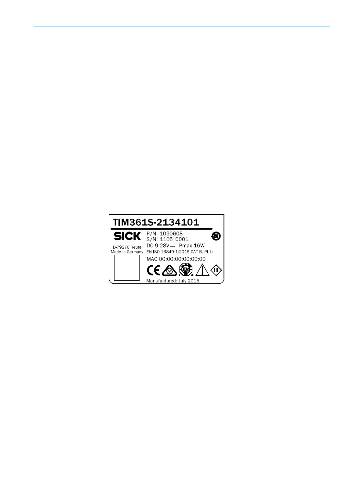
Item description: TiM361S-2134101
Design: PNP
Part no. 1090608
Valid firmware version: 2.59 or higher
SOPAS configuration software
Item description: SOPAS ET
Valid software version: 3.3.3 or higher
3.1 Scope of delivery
TiM361S--2134101 including mounting kit 1
(two straight plates, 2 M3 x 4 mm screws)
Printed safety notes with reference to the operating instructions in German and
English; in other languages via the SICK AG website, if required
Other optional accessories (if these have been ordered)
3.2 Type label
8022483/108R/2018-07-09 | SICK SAFETY-RELATED 2D LIDAR SENSOR | TIM361S
Subject to change without notice
11
Page 12
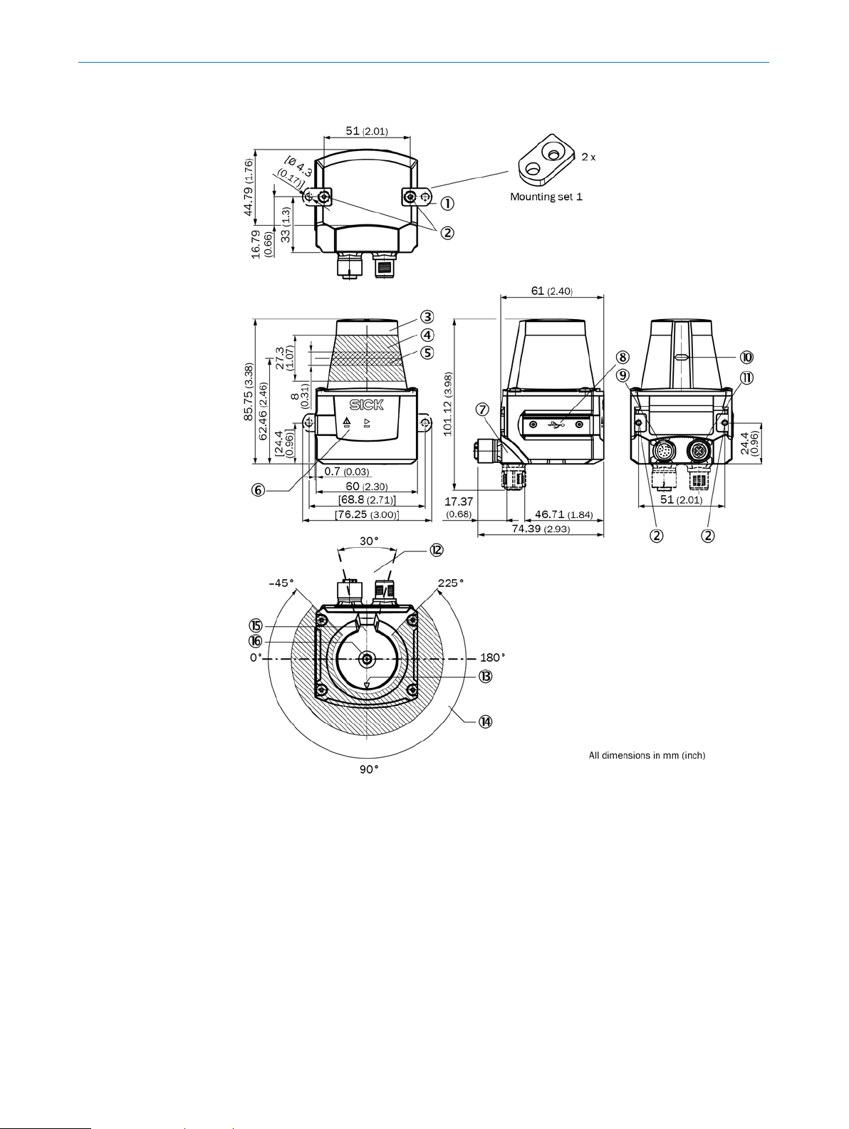
3.3 Device layout
3 PRODUCT DESCRIPTION
1 2 x straight plates with M3 x 4 mm screw (included in scope of delivery)
2 M3 threaded mounting hole, 2.8 mm deep (blind hole thread)
3 Optics cover
4 Receiving range (light inlet)
5 Transmission range (light emission)
6 Red and green LED (status displays)
7 Swivel connector unit with electrical connections
8 Micro USB port, behind the black plaster cover ("Aux interface" connection for
configuration with PC)
9 "Power/inputs and outputs" connection, 12-pin M12 male connector
10 Marking for the position of the light emission level
11 Connection (4-pin M12 female connector: not used)
12 Area in which no reflective surfaces are permitted when the device is mounted
13 Bearing marking to support alignment (90° axis)
14 270° aperture angle (visual range)
15 Internal reference target
16 Measurement origin
SAFETY-RELATED 2D LIDAR SENSOR | TIM361S 8022483/108R/2018-07-09 | SICK
12
Subject to change without notice
Page 13
3 PRODUCT DESCRIPTION
Ø 4.3
2 x Ø 4.3
39.1
26.4
12.1
101.5
68.8
68.8
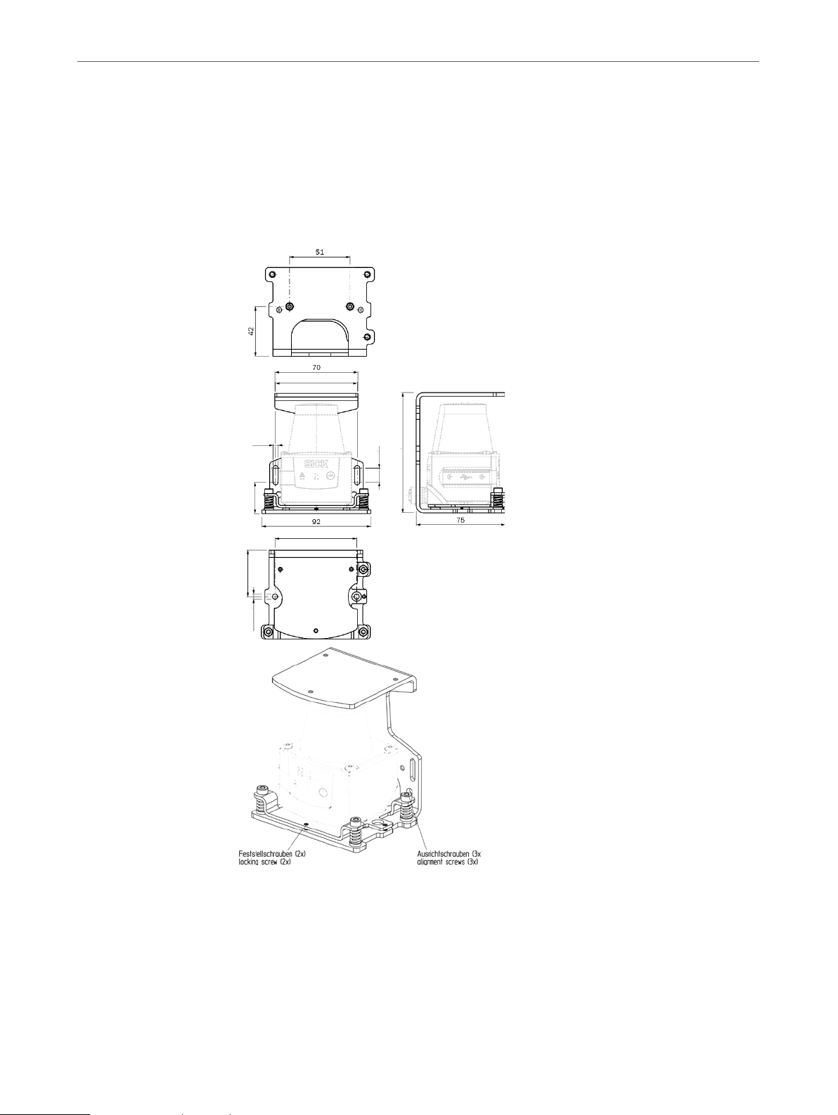
3.4 Accessories
The following accessories are permissible for safety-related use in connection with the
TiM361S.
Mounting kit with fine adjustment (2086761)
The mounting kit acts as a bracket, incl. the option of performing fine adjustment of the
scan level, and provides impact protection. The sensor can also be mounted directly on
the bracket without the adapter plate (mechanical collision protection only).
8022483/108R/2018-07-09 | SICK SAFETY-RELATED 2D LIDAR SENSOR | TIM361S
Subject to change without notice
13
Page 14
3 PRODUCT DESCRIPTION
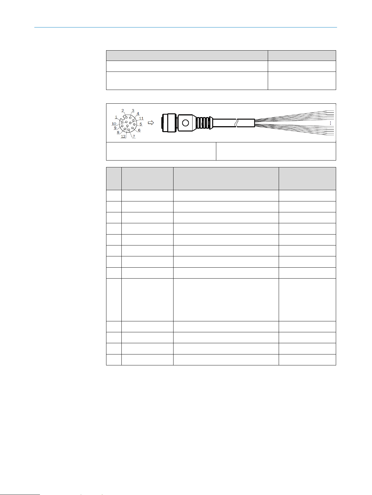
Cables
Designation Part number
USB – Guide for configuring the sensor 6036106
M12 female connector – open, 5 m, 12-wire, shielded,
6054974
PUR, halogen-free
Wire assignment, part number 6054974
M12 female connector, 12-pin,
A-coded (frontal view)
PIN Signal Function Wire color,
1 GND Ground Blue
2 DC 9 V … 28 V Supply voltage Brown
3 IN 1 Switching input 1 (field set selection) Red
4 IN 2 Switching input 2 (field set selection) Green
5 OUT 1 Switching output 1 (field breach) Pink
6 OUT 2 Switching output 2 (field breach) Yellow
Illustration may differ
connection
6054974 (5 m)
7 OUT 3 Switching output 3 (field breach) Black
8 OUT 4 Switching output 2 (index/error) Gray
9 PNP:
INGND
NPN:
IN DC 9 V … 28 V
PNP:
Common ground for all inputs
NPN:
Common reference potential of all
White
inputs
10 IN 3 Switching input 3 (field set selection) Violet
11 IN 4 Switching input 4 (field set selection) Gray-pink
12 N. c. - Red-blue
- - Shield
SAFETY-RELATED 2D LIDAR SENSOR | TIM361S 8022483/108R/2018-07-09 | SICK
14
Subject to change without notice
Page 15

3 PRODUCT DESCRIPTION
Measurement principle
The TiM361S is an opto-electronic 2D LiDAR sensor that uses laser beams to scan the
outline of its surroundings on a plane. The TiM361S measures its surroundings in twodimensional polar coordinates, relative to its measurement origin in the middle of the
optics cover. The arrow visible on the optics cover marks the 90° angle as the middle
of the scanning range. If a laser beam strikes an object, the position of that object is
determined in terms of length (distance) and direction (angle).
The sensor uses a rotating mirror to deflect the emitted laser beams, thereby scanning
its surroundings in a circular pattern across a 270° segment. The measurements are
triggered internally by an encoder in regular angle increments.
The TiM361S works with a scanning frequency of 15 Hz (15 measurements per
second).
Safety function
The sensor is intended for use in personal protective equipment for detecting safetyrelated objects in mobile and stationary applications in industrial environments.
It additionally has a safety function (also see chapter 5.5.1 Operating modes/Statuses)
In its normal functioning (monitoring mode) the safety function is to report the
presence or penetration of detected objects in its active protective fields.
The TiM361S meets the requirements of performance level b (PL b), Category B, per
EN ISO 13849 and can be used within its area of application for risk reduction
according to its features.
8022483/108R/2018-07-09 | SICK SAFETY-RELATED 2D LIDAR SENSOR | TIM361S
Subject to change without notice
15
Page 16

3.5 Safety characteristic values
The TiM361S safety-related laser scanner has the following safety characteristic values
per EN ISO 13849-1:2015:
Performance level (PL): b
Category (Cat.): B
3 PRODUCT DESCRIPTION
Mean Time To Dangerous Failure (MTTF
(at 25° ambient temperature)
Mission Time (MT) (period of use): 10 years
3.6 Safety-related detection capability
With the TiM361S safety-related laser scanner, with its emission wavelength, the
following objects can be reliably and safely detected up to a relative speed of 1.6 m/s
and at min. 5% remission:
Objects 50 mm in diameter and 400 mm in length (standing up) at a distance of
0.05 m up to max. 1.5 m with a horizontal protective field
Objects 70 mm in diameter and 400 mm in length (standing up) at a distance of
0.05 m up to max. 2 m with a horizontal protective field
Objects 200 mm in diameter and 600 mm in length in or penetrating a vertical
protective field and those lying on the ground with a horizontal protective field, at
a distance of 0.05 m up to max. 4 m
Restrictions
The safety-related detection capability (determined by the measurement procedure)
can be impaired for measurement of objects with edges and/or corners and/or those
moving too quickly. This can result in incorrect distance values, causing impairment,
reduction or complete loss of detection capability, and the device no longer being able
to perform its function.
Blind zone
): 100 years
D
No objects will be detected within a range of 0.05 m from the measurement origin,
across the entire scanning range of the TIM361S!
NOTE
Due to the necessary system reserve of the TiM361S, its detection range and/or
system range is greater than the assured distances for safety-related detection.
This system reserve must not be used for safety-related analysis!
SAFETY-RELATED 2D LIDAR SENSOR | TIM361S 8022483/108R/2018-07-09 | SICK
16
Subject to change without notice
Page 17

4 MOUNTING
4 Mounting
4.1 Notes on mounting
Mount the TiM361S safety-related laser scanner using the optionally available
mounting accessories (see chapter 3.4 "Accessories").
Mount the TiM361S on a prepared bracket. The sensor should be mounted and
operated as free from shock and vibration as possible.
The TiM361S can be mounted in any position depending on the application
purpose.
Mount the TiM361S so that it is not exposed to direct sunlight (window, skylight)
or other sources of heat. This prevents the temperature inside the device from
increasing unacceptably as well as the reduction or loss of detection capability.
During mounting, make sure there is no reflective surface behind the internal
reference target (see chapter 3.3 "Device Structure").
In general, the mounting position of the sensor should be chosen such that in the
sensor’s rear range (behind the internal reference target, see chapter 3.3
Structure"), dazzle due to other light sources is excluded, in order to prevent
reduction or loss of detection capability.
"Device
4.2 Mutual interference
The TiM361S safety-related laser scanner has been designed to minimize the
probability of mutual interference with sensors of the same type as the TiM361S. To
rule out even the slightest effects on the measurement accuracy, the devices should be
arranged such the laser beams are not received by another device.
8022483/108R/2018-07-09 | SICK SAFETY-RELATED 2D LIDAR SENSOR | TIM361S
Subject to change without notice
17
Page 18

5 Commissioning and configuration
Electrical block diagram for commissioning:
TiM361S-2134101
5.1 Notes on the electrical installation
Requirements for the IP 65/IP 67 enclosure rating: the black rubber plate (USB
female connector) must be flush-mounted on the housing.
Protect the TiM361S against moisture and dust when the cover to the USB female
connector is open.
Electrical connections between the sensor and other devices may only be made or
separated in a voltage-free state. Otherwise, the devices may be damaged.
Wire cross-sections in the supply cable from the customer’s power system should
be chosen in accordance with the applicable standards.
All electrical circuits connected to the sensor must be configured as SELV or PELV
circuits (SELV = Safety Extra Low Voltage, PELV = Protective Extra Low Voltage).
The supply voltage of the TiM361S must be secured accordingly.
Only switch on the supply voltage to the sensor when the connection tasks have
been completed and the wiring has been thoroughly checked.
5 COMMISSIONING AND CONFIGURATION
5.2 Prerequisites for safe electrical operation
The sensor is designed and tested for electrical safety in accordance with
IEC 61010-1:2010-06.
It is connected to the peripheral devices (voltage supply, control, actuators) via
shielded cables. The cable shield – for the supply cable, for example – rests against
the metal housing of the TiM361S. The device can either be grounded through the
cable shield or through both fastening latches.
If the peripheral devices have metal housings and if the cable shields also lie on their
housings, it is assumed that all devices involved in the installation have the same
ground potential.
This is achieved by complying with the following conditions, among others:
Mounting the devices on conductive metal surfaces
Correct grounding of the devices/metal surfaces in the system
Low-impedance and current-carrying equipotential bonding between areas with
different ground potentials, if necessary.
If these conditions are not met, e.g., on devices in a widely distributed system over
several buildings, potential equalization currents may, due to different ground
potentials, flow along the cable shields between the devices and create hazards or
malfunctions.
SAFETY-RELATED 2D LIDAR SENSOR | TIM361S 8022483/108R/2018-07-09 | SICK
18
Subject to change without notice
Page 19

5 COMMISSIONING AND CONFIGURATION
Control for
TiM361S
Voltage
supply
Closed current loop with
equalizing currents via cable
shield.
Grounding point
Ground potential
Grounding point
= Metal housing
= Shielded electrical cable
switching inputs
Actuators for
switching outputs
Due to insufficient ground potential equalization, voltage differences arise between
grounding points 1 and 2. The current loop closes via the shielded cables and metal
housing.
DANGER
Risk of injury/risk of damage due to electrical current!
Potential equalization currents between the TiM361S and other grounded devices in
the system can have the following effects:
Dangerous voltages on the metal housing
Incorrect function or irreparable damage to the devices
Damage/irreparable damage of the cable shield due to heating and cable fires
Where local conditions are unfavorable and thus do not meet conditions for a safe
earthing method (same ground potential at all grounding points), take measures
in accordance with the following formats.
Remedial measures
The most common solution to prevent potential equalization currents on cable shields
is to ensure low-impedance and current carrying equipotential bonding. If this is not
possible, the following solution approaches serve as a suggestion.
Important! We expressly advise against opening up the cable shields. This would mean
that the EMC limit values can no longer be guaranteed.
Measures for widely distributed system installations
On widely distributed system installations with correspondingly large potential
differences, we recommend setting up local islands and connecting them using
commercially available electro-optical signal isolators. This measure achieves a high
degree of resistance to electromagnetic interference.
8022483/108R/2018-07-09 | SICK SAFETY-RELATED 2D LIDAR SENSOR | TIM361S
Subject to change without notice
19
Page 20

5 COMMISSIONING AND CONFIGURATION
Control for
Electro-
isolator
Electro-
TiM361S
Grounding point 1
Grounding point 2
= Metal housing
= Shielded electrical cable
= Optical fiber
Control for
TiM361S
Voltage
Grounding point 1
Grounding point 2
Grounding point 3
= Metal housing
= Shielded electrical
Insulated mounting
Ground potential differential
switching inputs
Actuators for
switching outputs
optical
Ground potential differential
optical
isolator
The ground loop is isolated by using the electro-optical signal isolator between the
islands. Within the islands, stable equipotential bonding prevents equalizing currents
on the cable shields.
Measures for small system installations
For smaller installations with only slight potential differences, insulated mounting of the
sensor and of peripheral devices may be a sufficient solution.
switching inputs
Actuators for
switching outputs
supply
SAFETY-RELATED 2D LIDAR SENSOR | TIM361S 8022483/108R/2018-07-09 | SICK
20
Subject to change without notice
cable
Even in the event of large differences in the ground potential, ground loops are
effectively prevented. As a result, equalizing currents can no longer flow via the cable
shields and metal housing.
Important! The voltage supply of the TiM361S safety-related laser scanner and of the
connected peripheral devices must also guarantee the required insulation level. Under
certain circumstances, a tangible potential can develop between the insulated metal
housings and the local ground potential.
Page 21

5 COMMISSIONING AND CONFIGURATION
5.3 Installation of SOPAS Engineering Tool
System requirements for SOPAS ET, version 3.3.3
System Minimum requirement
Processor Standard Intel Pentium PC or compatible, at minimum
Pentium III 500 MHz
Frequency and working
memory
Interface USB 2.0 or compatible
Operating system Windows XP, Vista, Windows 7 or Windows 8 (32/64 bit)
Minimum resolution 1024 x 768 px
Memory At least 450 MB
5.3.1 Installation process
When selecting between "installation" and "portable version," always choose the
"installation" version. This ensures that all SOPAS ET functions and drivers are
available. For installation, it may also be necessary to have administrator
authorizations.
1. Select the installation language.
This selection only determines the language of the installation wizard. Regardless
of the selected installation language, all SOPAS ET languages can be selected
subsequently.
2. Chose whether you want to have an icon on the desktop or on the Start Menu bar,
and click Next >.
3. Select the installation location for SOPAS ET.
It is recommended not to change the suggested location.
Min. 1 GHz / 1 GB RAM
4. Click Next>.
The installation process starts. Please wait until it is fully complete and the next page
appears. The checkbox Run SOPAS Engineering Tool is preselected.
5. Use the Close button to complete the installation and launch SOPAS ET.
5.3.2 Installing the device driver
Installing the device driver for the TiM36S device occurs automatically the first time a
connection is established between SOPAS ET and the device.
8022483/108R/2018-07-09 | SICK SAFETY-RELATED 2D LIDAR SENSOR | TIM361S
Subject to change without notice
21
Page 22

5.4 Configuration of the sensor
Configuration of the sensor is done with SOPAS ET PC software.
DANGER
Risk of ineffectiveness of the protective device
Before establishing a connection between SOPAS ET and the TiM361S safety-
related laser scanner and before beginning configuration, ensure that the
machine, plant or application in which the TiM361S is involved as part of a safety
function is in a safe state.
5.4.1 Establishing the connection
Before launching SOPAS ET, a suitable cable (see chapter 3.4 "Accessories") must be
used to establish a USB connection between the configuration interface of the
TiM361S and the PC.
Double-click the program icon to start SOPAS ET – a new project is opened.
A quick search for connected devices is performed.
5 COMMISSIONING AND CONFIGURATION
The progress bar shows how far the process has progressed. The x symbol to the
right of the progress bar enables you to end the search process prematurely.
Found devices are listed in the search results window. If the TiM361S was
previously connected to the PC via USB, it will appear in the search results.
Found devices can be inserted into the project from the search results area via drag &
drop, double-click, the Enter key, or the Add icon. They will remain in the search results
but are displayed in gray.
Devices can only be configured and observed if they are inserted into the project.
No actions can be performed on the device in the search results window.
A device driver must be installed before establishing a connection with the TiM361S for
the first time. Follow the instructions provided by SOPAS ET. When selecting the source
for the driver installation, choose the option "Upload from device."
5.4.2 Configure the device
To configure a device, double-click on the desired device.
This opens the device window which displays all the device parameters. You can
configure the device, download parameters to and from the device, or observe
parameter values in this window.
The parameter values then also remain in the project after you close the device
window.
Only when the main window is closed will you be informed that parameters must be
permanently saved in the device and parameter values will be lost if the project has not
been saved.
SAFETY-RELATED 2D LIDAR SENSOR | TIM361S 8022483/108R/2018-07-09 | SICK
22
Subject to change without notice
Page 23

5 COMMISSIONING AND CONFIGURATION
5.4.3 Display of the current operational status
The "Monitor field analysis" page (in the navigation area of the device window, below
the "monitor" node) displays the current operational status consisting of measurement
data, status of the individual fields as well as status of the switching inputs and
outputs.
The field monitor, which is placed in the middle of the page, displays measurement
data as blue points and/or a blue line. Penetrated fields are shown in yellow; free fields
appear in green.
5.4.4 Changing parameters
DANGER
Risk of injury/risk of damage due to incorrect parameters!
Parameter changes are transferred to the device and take effect immediately
after being edited. Permanent saving (in the non-volatile memory of the device)
does not occur, however, until the "Save permanently" button is clicked.
After parameter changes, the effectiveness of the protective device in the
application must be reviewed and documented.
Before beginning configuration ensure that the machine, plant or application in
which the TiM361S is involved as part of a safety function is in a safe state.
Please note:
The individual parameters of the device can be changed on the pages below the
"Parameters" node in the navigation area.
The TiM361S must be configured using the SOPAS configuration software.
5.4.5 Default configuration
The product is delivered with the following default configuration, which prevents
unintentional or unaware sensor activation.
DANGER
Risk of ineffectiveness of the protective device
After configuring the product or after making parameter changes, the
effectiveness of the protective device in the application must be reviewed and
documented.
For a safety-related use of the TiM361S, the configuration and commissioning must
only be performed by appropriately qualified personnel (see also Qualification).
8022483/108R/2018-07-09 | SICK SAFETY-RELATED 2D LIDAR SENSOR | TIM361S
Subject to change without notice
23
Page 24

5 COMMISSIONING AND CONFIGURATION
Particle filter
Default: Particle filter is "deactivated"
The particle filter should be deactivated, since otherwise objects that appear
sporadically and for a short time will not be detected and/or filtered out. Similarly, the
particle filter also delays the functioning of the switching outputs.
Teach button
Default: TeachIn (SOPAS) is deactivated ("TeachIn disabled")
The TeachIn function (including via switching input) is deactivated in order to prevent
unintentional configuration.
Duration time for the outputs
Default: Maximum (Duration Time) on the outputs
The sensor automatically releases its protective field outputs when no more objects are
detected. The maximum output delay (duration time) therefore prevents immediate
restart.
Important! Continuous restart interlock with reset function must be implemented by
the user in the application.
SAFETY-RELATED 2D LIDAR SENSOR | TIM361S 8022483/108R/2018-07-09 | SICK
24
Subject to change without notice
Page 25

5 COMMISSIONING AND CONFIGURATION
Response time for object detection
Default: Minimum Response Time for object detection
The shortest configurable response time is preset to 67 ms and represents the most
rapid object detection.
Object sensitivity
Default: Maximum "sensitivity" (Blanking Size) for object detection
The smallest configurable blanking size of 10 mm represents the greatest degree of
object detection (i.e., the smallest detectable object).
8022483/108R/2018-07-09 | SICK SAFETY-RELATED 2D LIDAR SENSOR | TIM361S
Subject to change without notice
25
Page 26

5 COMMISSIONING AND CONFIGURATION
Switching outputs/Index signal
Default: Set all outputs to "active low" in PNP version
With its PNP switching outputs, the TiM361S safety-related laser scanner applies the
principle of energy release as an active status by using the "active low" logic.
Index Signal
Default: Index Signal is "active"
The index signal can be used as a "live signal" for the TiM361S safety-related laser
scanner by a downstream controller.
SAFETY-RELATED 2D LIDAR SENSOR | TIM361S 8022483/108R/2018-07-09 | SICK
26
Subject to change without notice
Page 27

5 COMMISSIONING AND CONFIGURATION
Protective fields
Default: No protective fields are configured, i.e., all field points, segments of a
protective field are deleted (no entries).
For all fields in all field sets, the reference contour (Contour as Reference) is
"deactivated".
Deleting the field points means that the corresponding outputs for signaling protective
field infringements are active (active low) until they are actively changed.
When the field points are deleted, the field editor will not display any protective fields!
5.4.6 Passwords
Software access to the TiM361S is protected by various passwords. After configuring
the device successfully, the respective password must be changed so that it can fulfill
its protective function.
The "Maintenance" user level enables parameter changes to be saved, among other
things.
The "Authorized client" user level allows for general sensor configuration.
5.5 Editing fields
Fields can be created and edited on the "Analysis fields" page (below the "Parameters"
node).
User level Password factory settings
Maintenance sicksafe98
Authorized client sicksafe99
Before editing a field, first select the desired field set itself and the desired field within
the field set.
Field set no. 1 and Field no. 1 are preset.
Different from all other parameters, changes to fields (adding, moving or removing
individual field points or entire fields) are not transferred to the device until the
"Download all fields to device" button is clicked.
8022483/108R/2018-07-09 | SICK SAFETY-RELATED 2D LIDAR SENSOR | TIM361S
Subject to change without notice
27
Page 28

5.5.1 Operating modes/operational statuses
The TiM361S safety-related laser scanner has the following operating modes and
operational statuses:
Power On and boot phase
Begins after connecting and/or interruption of the supply voltage, and ends with
operational readiness or fault/error
Operational readiness
Begins after Power On and boot phase, and ends 1 min or more after connection of the
supply voltage. Operational readiness is indicated optically by the "green" LED on the
device.
Operational status (monitoring mode)
(See also Normal functioning)
The TiM361S automatically enters this status after reaching operational readiness and
after the output "Device Ready" (OUT4) has changed to the "high" status. To do so, the
TiM361S must not be in configuration mode. (See Configuration mode)
Configuration mode
5 COMMISSIONING AND CONFIGURATION
Once the sensor is connected to the SOPAS configuration software via the USB
interface, the sensor can be configured.
The output "Device Ready" remains unchanged until write access to the device is
initiated by SOPAS (e.g., changing a parameter, downloading field data, or accessing
the "Save permanently" function), then the output "Device Ready" (OUT4) enters the
status "low" for a period of approx. 1 s.
Fault/error
The TiM361S automatically enters this status when it detects an internal error. If there
is an internal error, the output "Device Ready" (OUT4) is deactivated and enters the
"low" status. This status is shown optically on the device.
Safety function
The TiM361S safety-related laser scanner has a safety function.
The safety function is detecting the presence or penetration of an object in a defined
detection field (protective field).
When the safety function is requested, the Defined status is entered within max.
134 ms (max. 2 scans) and the safety-related output signals (OUT1-3) assigned
according to the detection field are switched off. (deactivated status)
Example:
When a mobile platform approaches a person, a protective field can trigger an optical
or acoustic signal. If the person does not respond and the mobile platform continues to
approach, the infringement of an additional protective field by the person can be used
SAFETY-RELATED 2D LIDAR SENSOR | TIM361S 8022483/108R/2018-07-09 | SICK
28
Subject to change without notice
Page 29

5 COMMISSIONING AND CONFIGURATION
to stop the mobile platform via the associated safety outputs, before it reaches the
person.
Defined statuses
The TiM361S has three defined statuses.
When the safety function is requested, defined Status 1 is to switch off (deactivated
status) the safety-related output signal (OUT1, OUT2, OUT3) assigned according to the
detection field.
Defined Status 2 is the status in which one or more of the safety-related output signals
(OUT1, OUT2, OUT3) has entered the switched off (deactivated) status while the safety
function was not requested.
Defined Status 3 is the status in which the safety-related output signal "Device Ready"
(OUT4) has entered the switched off (deactivated) status for more than 67 ms.
Response times for defined statuses
Upon request of the safety function, the sensor enters defined status 1 with a
response time of 134 ms or less (max. 2 scans).
It enters defined status 2 with a response time of 3,000 ms or less (15 scans) and
defined status 3 with a response time of 3,000ms or less (15 scans).
Protective field analysis
In its normal functioning (monitoring mode), the TiM361S reports, with an angular
resolution of 0.33° in its detection field (detection range), the presence or penetration
of detected objects in its active protective fields.
Protective fields
The TiM361S can simultaneously analyze 3 independent protective fields (detection
fields). Each protective field is assigned to a digital output OUT1, OUT2, OUT3 which is
activated upon infringement of the protective field (active low). The 3 independent
protective fields are configured in a field set in the TiM361S and saved.
If a field set change occurs, the sensor activates analysis of the new protective fields
with a response time of 134 ms or less (max. 2 scans).
Field sets
The sensor has 16 independent field sets. Selection of the active field set, and
therefore also of the active protective fields, is performed via inputs IN1, IN2, IN3, IN4.
8022483/108R/2018-07-09 | SICK SAFETY-RELATED 2D LIDAR SENSOR | TIM361S
Subject to change without notice
29
Page 30

5.5.2 Digital inputs/outputs
The TiM361S has the following safety-related interfaces, the statuses of which only
become valid after operational readiness is reached (see also Operating
modes/operational statuses):
Digital inputs
The sensor has 4 digital PNP switching inputs (IN 1-4), which by means of selecting the
corresponding binary combination (see table, below), activate one of the 16 available
field data sets, and therefore the active protective fields.
5 COMMISSIONING AND CONFIGURATION
Field set factory settings – switching inputs:
Field set Switching inputs
IN 1 IN 2 IN 3 IN 4
1 0 0 0 0
2 1 0 0 0
3 0 1 0 0
4 1 1 0 0
5 0 0 1 0
6 1 0 1 0
7 0 1 1 0
8 1 1 1 0
9 0 0 0 1
10 1 0 0 1
11 0 1 0 1
12 1 1 0 1
13 0 0 1 1
14 1 0 1 1
15 0 1 1 1
16 1 1 1 1
SAFETY-RELATED 2D LIDAR SENSOR | TIM361S 8022483/108R/2018-07-09 | SICK
30
Subject to change without notice
Page 31

5 COMMISSIONING AND CONFIGURATION
Input level:
PNP: Low (in resting position): ≤ 2 V, high (in working position): ≥ 8 V
Characteristic data of the switching inputs:
The characteristic data is identical for of all switching inputs.
Switching behavior Current to the input starts the assigned function in the
Properties Opto-decoupled
PNP electrical values Low: Ue ≤ 2 V, Ie ≤ 0.3 mA
device. Default: active high level, debounce 10 ms
Switchable with an electronic switch (PNP output) or
mechanical switch
High: 8 V ≤ U
≤ 32 V, 0.7 mA ≤ Ie ≤ 5 mA
e
Digital outputs
Infringement of the respective protective field is displayed in the active field data set by
means of 3 available digital PNP switching outputs (OUT1 … OUT3).
The factory setting for the digital outputs is the status "Field 1, 2, and 3 infringed."
Assignment of infringed fields – switching outputs:
Fields of a field set Switching outputs
OUT 1 OUT 2 OUT 3
Fields 1, 2, and 3
Active Active Active
infringed
Fields 2 and 3
Disabled Active Active
infringed
Field 3 infringed Disabled Disabled Active
All fields free Disabled Disabled Disabled
Field 1 inside, Field 2 middle, Field 3 outside
Active: in working position; deactivated: in resting position
8022483/108R/2018-07-09 | SICK SAFETY-RELATED 2D LIDAR SENSOR | TIM361S
Subject to change without notice
31
Page 32

5 COMMISSIONING AND CONFIGURATION
Initial level:
The level of the PNP switching outputs OUT 1 … OUT 3 is active low (deactivated status,
resting position: high, in working position: low (field infringed)).
All fields of a field set are considered infringed upon switching on, booting, in the event
of an error and when the device is switched off.
PNP switching output 4 works with the following levels:
Function Level
Device ready High
Index signal (15 Hz),
Low peaks
corresponds to
measurement at 90°
Error Low
Characteristic data of the switching outputs:
PNP switching
behavior
Properties Short-circuit protected and temperature protected
PNP electrical
values
Important! Longer connecting cables at the switching outputs of the device should be
avoided due to the resulting fall in voltage. This is calculated as follows:
PNP switching to supply voltage Uv.
OUT1 … OUT3:
resting level: high (no field infringement),
working level: low (field infringement)
response time 134 ms … 30 s (configurable via SOPAS ET ),
Duration time: 0 ms … 10 s (configurable via SOPAS ET)
OUT4:
resting level: high (Device Ready),
working level: low (error), low-impulse (15 Hz, index,
corresponds to measurement at 90°)
Not electrically isolated from supply voltage U
v
0 V ≤ Ua ≤ UV
– 1,5 V) ≤ Ua ≤ UV where Ia ≤ 100 mA
(U
V
ΔU = 2 x length x current / conductance value x cross-section
2
Conductance value for copper 56 m/Ω mm
SAFETY-RELATED 2D LIDAR SENSOR | TIM361S 8022483/108R/2018-07-09 | SICK
32
Subject to change without notice
Page 33

5 COMMISSIONING AND CONFIGURATION
5.5.3 Function and status displays
LED a (red) LED b (green)
Status
- Lights up Device ready/monitoring mode
Lights up Lights up Field infringement
Flashing - Error
- - Device without supply voltage
8022483/108R/2018-07-09 | SICK SAFETY-RELATED 2D LIDAR SENSOR | TIM361S
Subject to change without notice
33
Page 34

6 Error behavior
6.1 General
A non-hazardous failure of the laser scanner occurs:
• When the laser scanner switches to defined status 2 and/or 3 without request of
the safety function.
• When the laser scanner switches to defined status 2 and/or 3 in the event of a
detected internal error.
A hazardous undetected failure occurs:
• When the laser scanner fails to switch to defined status 1, defined status 2 and/or
defined status 3 upon request of the safety function.
6.2 Detected errors
The TiM361S detects some internal errors merely to improve its availability and
support troubleshooting in the event of a fault.
The sensor has diagnostic coverage (DC) of zero in accordance with EN ISO 13849-1
PL b. The internal errors detected by the sensor cannot be used to increase the DCs
within the meaning of this standard! (See also Error codes of the 2D LiDAR sensor)
6 ERROR BEHAVIOR
6.3 Undetected errors and faults
The TiM361S will not detect the following errors and faults, among others:
• Digital inputs:
wire break, short-circuit, cross-circuit to the digital inputs for field set selection (IN1,
IN2, IN3, IN4), making it possible to select an incorrect field set.
• Digital outputs:
wire break, short-circuit, cross-circuit to the digital outputs for field set infringement
(OUT1, OUT2, OUT3) and Device Ready (OUT4), with the effect that the defined
statuses can no longer be detected by the downstream controller.
• Status indicators:
Failure of the status indicators for field set status, with the result that infringement
of the protective field is not correctly displayed optically on the device.
• Contamination:
Contamination of the optics and/or the front screen, causing impairment, reduction
or complete loss of detection capability, and the device no longer being able to
perform the safety function.
• Ambient light:
Malfunctions due to faults of other scanners and light sources within the level of the
scan field, causing impairment, reduction or complete loss of detection capability,
and the device no longer being able to perform its function.
• Incorrect measurements:
Measurement of objects with edges and/or corners and/or which are moving too
quickly (determined by the measurement procedure) can result in incorrect distance
values, causing impairment, reduction or complete loss of detection capability, and
the device no longer being able to perform the safety function.
• Blind zone:
Objects, especially covering objects, located within the blind zone extending f
SAFETY-RELATED 2D LIDAR SENSOR | TIM361S 8022483/108R/2018-07-09 | SICK
34
Subject to change without notice
Page 35

6 ERROR BEHAVIOR
0.05 m from the measurement origin of the TIM361S, causing impairment,
reduction or complete loss of detection capability, and the device no longer being
able to perform the safety function.
Undetected errors and faults of the TiM361S can cause impairment, reduction or
complete loss of detection capability, such that the device is no longer able to perform
the safety function.
NOTE
As per EN ISO 13849-1 PL b, the sensor has diagnostic coverage (DC) of zero, i.e., it
must not detect errors and if they occur, can result in loss of the safety functions.
Testing and diagnostic measures can identify errors, such as those of the downstream
controller.
6.4 Fault exclusions
DANGER
Risk of ineffectiveness of the protective device
No fault exclusions have been specified for the sensor. The occurrence of faults can
result in the loss of the safety function.
6.5 Manipulation
The device does not have any protective measures against manipulation, especially
none that relate to the optical system. Objects, especially covering objects on the optics
cover and/or in the blind zone, are not detected by the TiM361S, causing impairment,
reduction or complete loss of detection capability, and the device no longer being able
to perform the safety function.
Manipulations with effects similar to undetected faults (see chapter 6.3 "Undetected
errors and faults") are also not detected.
8022483/108R/2018-07-09 | SICK SAFETY-RELATED 2D LIDAR SENSOR | TIM361S
Subject to change without notice
35
Page 36

7 Project planning
7.1 Manufacturer of the machine
DANGER
Risk of ineffectiveness of the protective device
Persons and parts of the body to be protected may not recognized in case of nonobservance.
Use of the sensor requires a risk assessment. Check whether additional protective
measures are required.
Comply with the applicable national regulations derived from the application (e.g.,
work safety regulations, safety rules, or other relevant safety guidelines).
Apart from the procedures described in this document, the components of the
device must not be opened.
The TiM361S must not be tampered with or changed.
Improper repair of the device can lead to loss of the safety function. The protective
device must only be repaired by the manufacturer or by someone authorized by
the manufacturer.
7 PROJECT PLANNING
7.2 Operating entity of the machine
DANGER
Risk of ineffectiveness of the protective device
Persons and parts of the body to be protected may not recognized in case of nonobservance.
Changes to the electrical integration of the sensor in the control of a machine and
changes to the mechanical mounting of the TiM361S safety-related laser scanner
necessitate a new risk assessment. The results of this risk assessment may
require the entity operating the machine to meet the obligations of a
manufacturer.
Changes to the device’s configuration may impair the safety function of the
TiM361S safety-related laser scanner. Therefore the device’s safety function and
the effectiveness of the protective device must be checked after any change in
configuration. The person carrying out the change is responsible for maintaining
the safety function of the device and the protective device.
The TiM361S must not be tampered with or changed.
Improper repair of the device can lead to loss of the safety function. The protective
device must only be repaired by the manufacturer or by someone authorized by
the manufacturer.
SAFETY-RELATED 2D LIDAR SENSOR | TIM361S 8022483/108R/2018-07-09 | SICK
36
Subject to change without notice
Page 37

7 PROJECT PLANNING
DANGER
Danger due to optical and electromagnetic ambient conditions
Optical and electromagnetic ambient conditions can impair the functioning of the
TiM361S.
This can result in loss of the safety function. Please note the following:
Avoid having strong electric fields in the vicinity of the laser scanner. These may
be caused by nearby welding or induction cables, for example.
Prevent condensation on and/or contamination of the optics cover. To ensure the
continuing, reliable safety function of the device, the optics cover must be cleaned
regularly.
8022483/108R/2018-07-09 | SICK SAFETY-RELATED 2D LIDAR SENSOR | TIM361S
Subject to change without notice
37
Page 38

8 Regular thorough checks
At regular intervals the user must demonstrate that the measures taken still fulfill the
protective purpose, and that the protective device still functions correctly in the
application during the service life.
Thorough checks and tests are required in this regard:
• Upon commissioning (e.g., initial commissioning, recommissioning)
• After changes and extraordinary events (e.g., conversion, change of parameters,
modification, retrofitting and equipment, damage, repair, ...)
• And at regular intervals (e.g., recurring thorough checks intended to ensure that a
safety function and/or safety function still functions correctly in the application)
These thorough checks must be documented clearly and comprehensibly.
Determination of the time intervals for thorough checks at regular intervals must be
decided and established by the manufacturer of the machine and/or by the operating
entity depending on the specific application, place of application and influencing
factors prevailing there. (e.g., dirt, demand rate, EMC, …).
Example: thorough check of the effectiveness of protective fields
The effectiveness of protective fields can be demonstrated, for example, by positioning
a suitable test object with the diameter and remission of the desired detection
capability at multiple points along the effective protective range, and having the sensor
detect them.
8 REGULAR THOROUGH CHECKS
SAFETY-RELATED 2D LIDAR SENSOR | TIM361S 8022483/108R/2018-07-09 | SICK
38
Subject to change without notice
Page 39

9 WORKING WITH THE PRODUCT
9 Working with the product
9.1 Maintenance and care
The TiM361S safety-related laser scanner does not contain any components that
require maintenance. The device must not be opened. Maintenance is not necessary to
ensure compliance with laser class 1, either.
The black, infrared-transparent optics cover should be cleaned, at regular
intervals and in the event of contamination, with a lint-free lens cloth
(part no. 4003353) and plastic cleaning agent (part no. 5600006). In this regard,
the cleaning interval essentially depends on the ambient conditions.
9.2 Transport and storage
The TiM361S safety-related laser scanner must be transported and stored in its
original packaging with the USB protective cap plugged in. Do not store outdoors. To
ensure that any residual moisture present can escape, do not store the device in
airtight containers. Do not expose to aggressive media (e.g. solvents).
Storage conditions: Dry, dust-free, no direct sunlight, as little vibration as possible,
storage temperature –40 to +75 °C, relative humidity max. 90% (non-condensing).
9.3 Repairs
Repair work on the TiM361S safety-related laser scanner may only be performed by
qualified and authorized service personnel from SICK AG.
9.4 Disassembly and disposal
Any TiM361S safety-related laser scanner which can no longer be used at the end of
the product life cycle must be disposed of in an environmentally-friendly manner in
accordance with the country-specific waste disposal regulations that are applicable at
the time.
The TiM361S safety-related laser scanner is electronic waste and must under no
circumstances be disposed of with general waste.
8022483/108R/2018-07-09 | SICK SAFETY-RELATED 2D LIDAR SENSOR | TIM361S
Subject to change without notice
39
Page 40

10 Technical data
10.1 General technical data
Characteristic Values
Field of view Radial, aperture angle 270°
Angular resolution 0.33°
Scanning frequency 15 Hz (15 scans/s)
10 TECHNICAL DATA
Detection range/system
distances
0.05 m … 4 m; at 5% remission
0.05 m … 8 m; at 10% remission
0.05 … 10 m, at > 50% remission
Minimum physical object
sizes
(cross-section)
121 mm at a distance of 8 m,
66 mm at a distance of 4 m,
38 mm at a distance of 2 m,
at respective remission
Light source Laser diode, infrared (λ = 850 nm +/- 10 nm)
Laser class Laser class 1 according to EN 60825-1 (eye-safe)
Max. radiated power 1.5 W
Max. pulse duration 5 ns
Configuration interface USB 2.0 for configuration, connecting cable max. 3 m
Electrical connections 1 x 12-pin M12 power male connector
1 x micro USB female connector, type B (covered)
Optical indicators 2 x LED
Supply voltage DC 9 … 28 V, SELV and PELV
according to IEC 60364-4-41
Power consumption Typical power consumption of 4 W with unloaded
switching outputs
Max. power consumption 16 W with max. four loaded
switching outputs
Protection The supply voltage must be protected with a max.
0.8 A slow-blow fuse (take into account the cable
cross-section of the wiring!)
Housing Lower part: aluminum die cast
Optics cover: polycarbonate with scratch-resistant
coating
Weight Approx. 250 g without cables
Electrical safety According to IEC 61010-1 (ed.3)
Protection class III, acc. to EN 61140: IEC 60010-1 (ed. 3)
Ambient light immunity 60,000 lx (indirect)
Ambient Temperature –10°…50 °C
Temperature change Thorough check N according to EN 60068-2-14
SAFETY-RELATED 2D LIDAR SENSOR | TIM361S 8022483/108R/2018-07-09 | SICK
40
Subject to change without notice
Page 41

10 TECHNICAL DATA
Characteristic Values
Damp heat According to EN 60068-2-30
Air humidity < 80% (non-condensing)
Enclosure rating IP67
Altitude max. 2,900 m ASL
EMC Residential area according to EN 61000-6-3
Industrial area according to EN 61000-6-2
Vibration resistance (according to EN 60068-2-6)
Shock resistance (in accordance with EN 60068-2-27)
Contamination Contamination level 1, EN 61010-1 outside housing
Contamination level 3, EN 61010-1 outside housing,
with sealed USB connection
(All specifications regarding contamination do not
apply to the optics)
For further technical specifications, see the Online data sheet on the product page on
the web (www.sick.com/tim3xx).
10.2 Safety-related technical data
Characteristic Values
Performance level (PL) PL b according to EN ISO 13849-1:2015
Category (Cat.) Cat. B according to EN ISO 13849-1:2015
Mean Time To Dangerous
Failure (MTTF
Mission Time (service life) 10 years
Safety-related detection
range
Safety-related detection
capability
Blind zone No objects are detected across the entire radial visual
)
D
100 years according to EN ISO 13849-1:2015
(at 25° ambient temperature)
0.05 m … 4 m; at 5 % remission
Objects 50 mm in diameter at a distance of 0.05 m
up to max. 1.5 m or
objects 70 mm in diameter at a distance of 0.05 m
up to max. 2 m or
objects 200 mm in diameter at a distance of 0.05 m
up to max. 4 m,
up to a relative speed of 1.6 m/s and at min. 5%
remission.
range (scanning range of 270°) from the
measurement origin up to a distance of 0.05 m
Response time Response of the switching outputs upon detection of
an object
Max. 134 ms (2 scans); typically 67 ms (1 scan)
8022483/108R/2018-07-09 | SICK SAFETY-RELATED 2D LIDAR SENSOR | TIM361S
Subject to change without notice
41
Page 42

10 TECHNICAL DATA
Characteristic Values
Protective field/Field
analysis
1 analysis case with 1 field set and up to
3 independent protective fields, signaling of field
infringements via a combination of 3 PNP switching
outputs (OUT1 … OUT3)
Protective field tolerance +100 mm; 0.66° acc. To DIN CLC/TS 62046:2009 at
5% remission
Temperature drift: 1.5 mm/Kelvin
Number of field sets 16 field sets with 3 independently configurable
protective fields each
Switching inputs PNP inputs: 4 x IN, IN1 … IN4,
= max. 28 V, Ie = max. 5 mA), opto-decoupled,
(U
e
debounce approx. 10 ms
Switching outputs PNP outputs: 4 x OUT, OUT1 … OUT4, (each Ia max.
100 mA), not electrically isolated from supply voltage,
short-circuit protected/ temperature protected
Configurable for OUT 1 … OUT 3:
Response time (67 ms … 30 s)
2
Duration time (0 ms … 10 s)
For further technical specifications, see the online data sheet on the product page on
the web (www.sick.com/tim3xx).
NOTE
The product is intended for use in industrial environments, under indoor conditions. It
is not suitable for use in special surroundings (e.g., radiation and sparks from welding
systems, strong sources of infrared, thermal convection, fluorescent and stroboscopic
light sources, snow, rain, contamination) or must yet be made suitable, if applicable.
2
The TiM has an internal, system-related time delay of 67 ms
SAFETY-RELATED 2D LIDAR SENSOR | TIM361S 8022483/108R/2018-07-09 | SICK
42
Subject to change without notice
Page 43

11 DECLARATION OF CONFORMITY
11 Declaration of conformity
EU declaration of conformity
The undersigned, who represents the manufacturer below, hereby declares that the
product complies with the regulations of the EU directive(s) below (including all relevant
changes), and that it is based on the relevant standards and/or technical
specifications.
Complete EU declaration of conformity for download
You can call up the EU declaration of conformity and the current operating instructions
for the product by entering the part number in the search field at www.sick.com.
(Part number: see the type label entry in the "P/N" field).
8022483/108R/2018-07-09 | SICK SAFETY-RELATED 2D LIDAR SENSOR | TIM361S
Subject to change without notice
43
Page 44

8022483
Australia
Phone +61 (0)3 9457 0600
1800 334 802 – toll free E-Mail
sales@sick.com.au
Austria
Phone +43 22 36 62 28 8-0
E-Mail office@sick.at
Belgium/Luxembourg
Phone +32 2 466 55 66
/108R/en/2018-07-09
E-Mail info@sick.be
Brazil
Phone +55 11 3215-4900
E-Mail marketing@sick.com.br
Canada
Phone +1 905 771 1444
E-Mail information@sick.com
Czech Republic
Phone +420 2 57 91 18 50
E-Mail sick@sick.cz
Chile
Phone +56 2 2274 7430
E-Mail info@schadler.com
China
Phone +86 20 2882 3600
E-Mail info.china@sick.net.cn
Denmark
Phone +45 (0)45 82 64 00
E-Mail sick@sick.dk
Finland
Phone +358-9-2515 800
E-Mail sick@sick.fi
France
Phone +33 (0)1 64 62 35 00
E-Mail info@sick.fr
Germany
Phone +49 (0) 211 5301-301
E-Mail info@sick.de
Hong Kong
Phone +852 (0)2153 6300
E-Mail ghk@sick.com.hk
Hungary
Phone +36 (0)1 371 2680
E-Mail office@sick.hu
India
Phone +91 (0)22 6119 8900
E-Mail info@sick-india.com
Israel
Phone +972 4 6881000
E-Mail info@sick-sensors.com
Italy
Phone +39 (0)2 27 43 41
E-Mail info@sick.it
Japan
Phone +81 (0)3 5309 2112
E-Mail support@sick.jp
Malaysia
Phone +6 03 8080 7425
E-Mail enquiry.my@sick.com
Mexico
Phone +52 (472) 748 9451
E-Mail mario.garcia@sick.com
Netherlands
Phone +31 (0)30 2044 000
E-Mail info@sick.nl
New Zealand
Phone +64 (0)9 415 0459
0800 222 278 – tollfree E-Mail sales@sick.co.nz
Norway
Phone +47 (0)67 81 50 00
E-Mail sick@sick.no
Poland
Phone +48 (0)22 539 41 00
E-Mail info@sick.pl
Romania
Phone +40 (0)356 171 120
E-Mail office@sick.ro
Russia
Phone +7 495 775 05 30
E-Mail info@sick.ru
Singapore
Phone +65 6744 3732
E-Mail sales.gsg@sick.com
Slovakia
Phone +421 482 901201
E-Mail mail@sick-sk.sk
Slovenia
Phone +386 591 788 49
E-Mail office@sick.si
South Africa
Phone +27 11 472 3733
E-Mail info@sickautomation.co.za
South Korea
Phone +82 (0)2 786 6321
E-Mail info@sickkorea.net
Spain
Phone +34 (0)93 480 31 00
E-Mail info@sick.es
Sweden
Phone +46 (0)10,110 10 00
E-Mail info@sick.se
Switzerland
Phone +41 41 619 29 39
E-Mail contact@sick.ch
Taiwan
Phone +886 2 2375-6288
E-Mail sales@sick.com.tw
Thailand
Phone +66 (0)2645 0009
E-Mail Ronnie.Lim@sick.com
Turkey
Phone +90 (0)216 528 50 00
E-Mail info@sick.com.tr
United Arab Emirates
Phone +971 (0) 4 8865 878
E-Mail info@sick.ae
United Kingdom
Phone +44 (0)1727 831121
E-Mail info@sick.co.uk
USA
Phone +1 800 325 7425
E-Mail info@sick.com
Vietnam
Phone +84 945452999
E-Mail
Ngo.Duy.Linh@sick.com
Further locations at www.sick.com
SICK AG | Waldkirch | Germany | www.sick.com
 Loading...