

Page 1
Connection module
DC 9 ... 28
ring
customer-
0,8A/T
0,8A/T
customer-
Scanning range in m (feet)
(13.12)
(13.12)
(19.69)
(19.69)
OPERATING INSTRUCTIONS
en
Safety information
• Read these instructions before commissioning the TiM31x
in order to familiarize yourself with the device and its
functions.
• Mounting and electrical installation are to be performed
only by qualied technicians.
• Electrical connections between the TiM31x and other
devices may only be connected or disconnected when
the system is not live. Otherwise, the devices could suffer
TiM31x
damage.
• Select and design conductor cross sections of the supply
cable from the customer's power system in accordance
with the applicable standards. If the supply voltage for the
Short range
Detecting laser scanner
TiM31x is not fed via the optional CDB730-001 connection
module, protect the TiM31x with an external 0.8 A delay-
action fuse at the start of the supply cable.
• All electrical circuits connected to the TiM31x must be
designed as SELV circuits (Safety Extra Low Voltage).
• Only use the device under permitted ambient conditions
(e.g. temperature, ground potential) ( see “Technical
specications, page 3”).
• Protect the TiM31x from moisture and dust when the cover
of the USB socket is open. So as to adhere to the IP 65
enclosure rating during operation, the black rubber plate
must be ush mounted on the housing.
• Do not open the TiM31x’s screw connection housing,
as doing so will invalidate any warranty claim against
SICK AG.
• The TiM31x does not constitute personal protection equipment in accordance with the respective applicable safety
standards for machines.
Commissioning and conguration
Indended use
The TiM31x laser scanner is an intelligent sensor for invis-
ibly detecting objects in areas to be monitored (elds). It is
designed for portable or stationary use indoors in standalone
operation, with a range of up to 4 m. Combined actuation via
the four switching inputs activates one of the 16 eld sets
as an evaluation case for eld monitoring. Each congurable
eld set offers three origin-oriented, partially overlapping
elds of uniform shape, but with different sizes. Field sets
with xed or freely denable shapes are available. The
TiM31x signals detected eld infringements in relation to the
three elds through a combination of three switching outputs.
The TiM31x is available in both a PNP and an NPN variant.
The NPN variant is identied by S02 in the type code on the
type label.
The purpose of this instruction manual is to allow you to put
the TiM31x into operation quickly and easily with predened
eld sets, and to achieve the rst detection results.
Further information concerning mechanical and electrical
installation can be found in the & Technical Information
(no. 8014318). This can be accessed on the TiM31x product
web page (www.mysick.com/de/tim31x).
8014316/YDQ9/2014-08-27 • Subject to change without notice • SICK AG • Waldkirch • Germany • www.sick.com TIM31X | SICK 1
Step 1: Electrical installation
Connect the TiM31x as followed, depending on the plug type
on the black connecting cable:
1. Connect the 15-pin D-Sub HD plug of the connecting cable
to the corresponding socket on the CDB730-001 connection module.
Connect the 12-pin M12 plug of the connecting cable to a
customer-provided connection box.
To do so, make a connection box with a 12-pin socket. This
is used like the connection module to connect the supply
voltage, and for signal routing of the switching inputs and
outputs (refer to the “Electrical installation” chapter in the
& Technical Information (no. 8014318)).
2. Connect the TiM31x’s Micro USB socket (behind the black
rubber plate on the side) to a free USB socket (type A) on
the PC using a suitable shielded high-speed USB cable
(e.g. no. 6036106, 2 m). Do not extend the cable!
3. Supply the TiM31x with voltage.
Using the power supply unit it must be ensured that the
supply voltage does not drop below 8 V for longer than
2 ms and never rises above 30 V. Following successful
initialization, the green LED “
operation).
– or –
▸” lights up (device ready for
Do not supply the switching inputs with current yet.
TiM31x
“USB 2.0”
TiM31x
USBUSB
SOPASSOPAS
Configuration
Field monito
Diagnosis
USBUSB
SOPASSOPAS
Configuration
Field monitoring
Diagnosis
CDB730-001
...
OUT 1
OUT 2
OUT 3
OUT 4
...
1
2
GND
V
“Power/I/O”
Electrical block diagram for commissioning the TiM31x provided with a
15-pin D-Sub HD plug on the cable
provided
OUT 1 OUT 3
OUT 2
Connection
delayaction
fuse
Electrical block diagram for commissioning the TiM31x variant PNP
provided with a 12-pin M12 plug on the cable
box
...
IN 1 IN 4
DC 9 ... 28 V
“USB 2.0”
“Power/I/O”
provided
OUT 1 OUT 3
OUT 2
Connection
delayaction
fuse
Electrical block diagram for commissioning the TiM31x variant NPN
provided with a 12-pin M12 plug on the cable
...
IN 1 IN 4
DC 9 ... 28 V
box
9 ... 28 V
IN
„Power/I/O“
„USB 2.0“
TiM31xS02
USBUSB
SOPASSOPAS
Configuration
Field monitoring
Diagnosis
Step 2: Mounting and alignment
NOTE
During installation make sure there is no reective surface
behind the reference target see “Device structure, page
â.
3”, point
1. Optionally, attach the TiM31x to the mounting accessories
ordered separately (mounting kit 2); see the “Mounting”
chapter in the & Technical Information (no. 8014318).
2. Otherwise, mount the two straight plates from the
enclosed mounting kit 1 on the TiM31x using 2 M3
screws. For this, use the two blind hole threads on either
the underside or the rear of the housing ( see “Device
structure, page 3”). If the straight plates are not used,
screw the screws provided by the customer max. 2.8 mm
into the thread.
3. Mount the TiM31x on a prepared bracket. The device
should be as free from vibration as possible during operation.
4. Align the 90° axis of the TiM31x’s scanning angle with the
center of the area to be monitored. The
mark on the
cover of the optical hood serves as an alignment aid for
direction nding ( see “Device structure, page 3”).
6
4
225°
2
(6.56)
0
2
(6.56)
4
‒45°
6
4
6
(13.12)
(19.69)
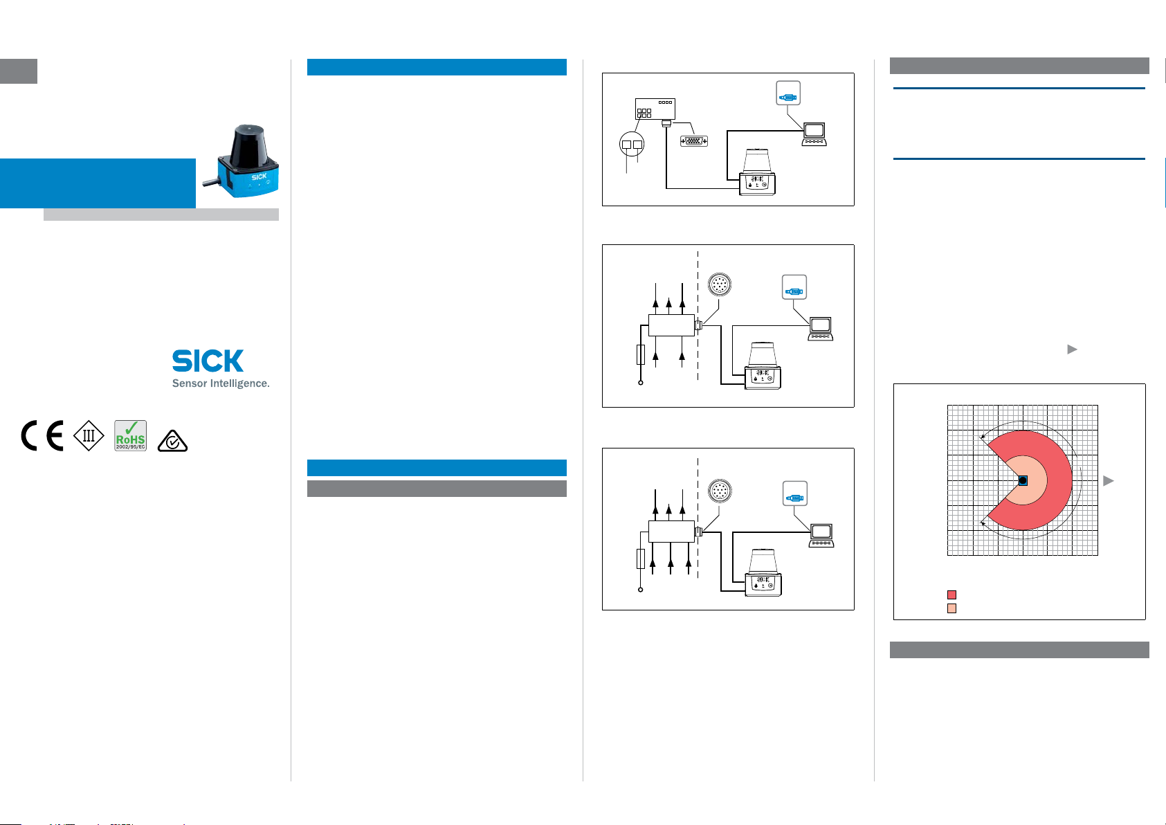
Scanning range max. 4 m (13.12 feet)
Scanning range for objects up to
Range diagram for TiM31x
(6.56)
180°
0°
2
0
270°
90°
2
(6.56)4(13.12)6(9.69)
Scanning range in m (feet)
Step 3: Conguration
a. Conguration without PC
The TiM31x offers two possibilities for this:
• Using one of 16 default eld sets, each with 3 predened
elds with the same eld shape, but different sizes.
• Teach-in of the surrounding contour to automatically gener-
ate the outer eld with any shape, including more complex
shapes, and to deduce the two inner elds.
The eld sets are organized into groups with the eld shapes:
Page 2
segmented (shape freely denable, default: rectangle), rect-
90°
angle and semi-circle (only the size of these last two can be
changed). The 3 origin-oriented elds of a set always overlap
to some extent and form a triple.
Field 3
Field 2
Field 1
0°180°
Semi-circle
Segmented,
free shape type
Structure of the elds of a eld set and possible eld shapes
Rectangle
The limits of the outer eld 3 and the middle eld 2 relate
to the limits of the inner eld 1. The relationship between
the limits is xed as a percentage for the eld sets 1 to 4;
the limits of eld 2 and eld 3 can be adjusted freely for the
eld sets 5 to 16 if needed, using the SOPAS conguration
software. The following rules apply: Field 1 may not be larger
than eld 2, and eld 2 may not be larger than eld 3; neither
may elds be congruent.
For the dimensions of the respective eld 1 and its default
shape as well as for the wiring of the switching inputs
required for eld set selection see “Field set – switching
input assignment, page 3”.
Preparing for teach-in
In general, the function button and two LEDs on the device
are used for teach-in.
• Remove all objects that will not permanently be in the eld
of view in monitoring mode later on.
• Distance yourself sufciently from the TiM31x during the
advance warning phase of the teach-in, so that you are not
detected as part of the eld contour.
Teaching in the eld contour
The TiM31x uses the eld set 1 (segmented, initial shape:
rectangle) to adjust the eld shape and size to the surround-
ing contour detected. The switching inputs may not be supplied with current during this process.
The TiM31x forms the outer eld 3 from the surrounding contour with a negative offset of 100 mm (3.94 in), and deduces
the limits of the two inner elds from this, so that eld 2 =
eld 1 plus 25 % and eld 3 = eld 1 plus 52 %.
• The eld shape to be formed can be dened by depreciat-
ing the limits during the teach-in phase. Do not wear black
clothing during this process!
> Start the eld contour teach-in.
3 seconds
= flashes slowly
The behavior of the two LEDs shows the progress of the eld
contour teach-in:
LED a
(red)
–
O O
–
–
O O
O = lit, = ashing
Status
LED b
(green)
Field contour teach-in – start
LED ashes slowly (0.5 Hz)
Field contour teach-in – advance warning
stage
LED ashes increasingly faster within 15 s
Field contour teach-in – teach-in phase
60 seconds
Field contour teach-in – end of teach-in phase
LED ashes increasingly faster within 15 s
Automatic return to monitoring mode
O
All elds free
Monitoring mode
In case of eld infringement
The TiM31x automatically stores the new eld set 1 perma-
nently.
b. Conguration with PC
By default, the 3 elds of a eld set and other parameters
of the TiM31x are adapted to the application and the
diagnostics are performed in case of a fault using the SOPAS
conguration software.
If the eld shape of the eld set 1 has been taught in without
a PC using the function button, in general SOPAS is used to
continue the conguration.
This includes continuing to set the eld shapes/sizes, nonteachable eld sets based on the default setting and the
response time of the elds, the blanking size and the holding
(duration) time of the assigned switching outputs OUT 1 ...
OUT 3.
The blanking size is the object diameter above which an
object not present in the TiM31x’s scanning angle leads to
a eld infringement. Like the response time and the holding
time, the blanking size applies to all eld sets and their elds.
Installing and starting the SOPAS conguration software
1. Download and install on the PC the software from the web-
site “www.mysick.com/en/SOPAS_ET”, SOPAS ET software
type. In this case, select the “Complete” option as selected
by the installation wizard. Administrator rights may be
required on the PC to install the software.
2. Once installation is complete, start the “Single Device”
program option.
Path: Start > Program Files > SICK > SOPAS Engineering
Tool > SOPAS (Single Device).
When SOPAS detects a connected TiM31x for the rst
time, it automatically installs the required USB driver. It
may be necessary to restart the PC at this point.
3. Establish a connection between SOPAS and TiM31x using
the wizard that opens automatically. Select the TiM31x
from the list of available devices.
SOPAS program window (Single Device)
Field monitor display window
• In the Field monitor window, SOPAS displays the eld
contour (scan line) currently seen in the reection of the
surroundings in blue. If the 4 switching inputs are not supplied with current, SOPAS also displays the three protective
elds (segmented rectangles) for the eld set 1 according
to the TiM31x’s default setting, or the eld shape gener-
ated using the teach-in function with its dimensions, the
status of the switching inputs/outputs and the position of
the mouse pointer.
• SOPAS displays the elds in green if no eld infringement
is present. If objects of a particular size and duration
( see “Default settings TiM31x, page 2”) are located
in the part of the scanning angle that is covered by elds,
the TiM31x recognizes this as a eld infringement. SOPAS
displays this separately for the individual elds in yellow.
When a CDB730-001 connection module is used, the
LEDs OUT 1 ... OUT 3 light depending of the eld infringe-
ment ( see “Assignment of infringed elds - switching
outputs, page 3”)
> Try changing the orientation of the TiM31x in the room
and observe the effects this has on detection in the eld
monitor.
Clicking the
reset button in SOPAS resets the counters on
the switching outputs.
Continuing conguration
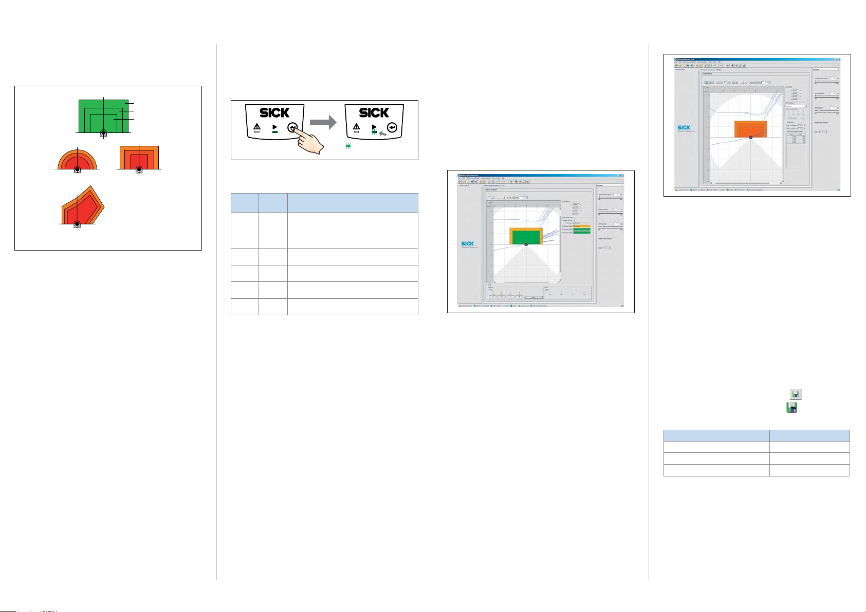
Field editor display window
1. To optimize the monitored elds of the eld sets used by
the TiM31x manually, click the
Field editor tab at the top of
the program window.
2. Select the eld set 1, for example, under
Field name on the
right of the window.
3. Adjust the settings for other functions such as response
times of the elds, blanking size and holding (duration)
time output under
settings on the right of the program
window. When selecting the response time, note that the
tim31x also has its own internal response time.
4. To check the effects of the settings applied, click the
monitor tab at the top.
Field
SOPAS displays the infringed elds in yellow in the eld
monitor for the eld set 1. If you wish to observe another
eld set, this must rst be activated accordingly using the
switching inputs.
Completing conguration
> Finally, save the entire conguration permanently:
Parameter set in the TiM31x: Click the
Conguration le on the PC: Click the
button.
button.
Default settings TiM31x
Parameter Value
Blanking size Diameter 200 mm (7.88 in)
Response time of the elds 335 ms (5 scans)
Holding time of the switching outputs 335 ms (5 scans)
TIM31X | SICK 8014316/YDQ9/2014-08-27 • Subject to change without notice • SICK AG • Waldkirch • Germany • www.sick.com2
Page 3

Description of the device
79 (3.11)
90°
Device structure
*)
(2.71)
68.8
51 (20)
Ø 4.3 (0.17)
1
38.3 (1.50)
8 (0.31)
27.3 (1.08)
55.8 (2.19)
*)
19.4
(0.76)
6
1 2 x straight plates with M3 x 4 mm screw (included in delivery)
2 M3 threaded mounting hole, 2.8 mm deep (blind hole thread)
3 Optical hood
4 Receiving range (light inlet)
5 Transmission range (light emission)
6 Red and green LED (status displays)
7 Function button for teach-in
8 Exit of either the 0.9 m (2.95 ft) connecting cable with 15-pin D-Sub
HD plug or the 0.8 m (2.62 ft) connecting cable with 12-pin M12
plug (“Power/switching inputs/outputs” connection).
9 Micro USB socket, behind black rubber plate
(“Aux interface” connection for conguration with PC)
ß Mark for the position of the light emission level
à Direction nding mark to aid alignment (90° axis)
á Aperture angle 270° (scanning angle)
â Area in which no reective surfaces are allowed for mounted devices
60 (2.36)
68.8 (2.71)
76.3 (3.0)
30°
2
3
4
5
*)
Ø 4.3
(0.16)
4.4 (0.17)
*)
*)
7
â
225°‒45°
á
Status displays, functions
Input level
• PNP: Low (in resting position): ≤ 2 V, high (in working
position): ≥ 8 V
• NPN: Active low (in working position): ≤ (IN 9...28 V) – 8 V,
*)
Mounting kit 1
*)
0.5
(0.02)
180°0°
à
All measures of length in mm (inch)
*)
2 x
ß
19.4
(0.76)
(2.36)
60
98
measures including straight plates
(2.00)
51
22
a CAUTION
Laser radiation
The TiM31x corresponds to laser class 1 (eye-safe).
The laser beam is not visible to the human eye.
Caution – incorrect use can lead to the user being exposed to
dangerous radiation.
> Do not open the TiM31x’s screw connection housing.
> Comply with the latest version of the applicable provisions
on laser protection.
For further information, see “Technical specications, page 3”.
Status displays
LED a
(red)
LED b
(green)
–
O O
–
O O
–
– –
O = lit; = ashing
Status
Device ready/monitoring mode
O
Field infringement
Teach-in – Start
Teach-in – end of advance warning phase
60 second teach-in phase
Teach-in – End of teach-in phase
Error
–
Device without supply voltage
Field set – switching input assignment
Field
Switching inputs Field shape
set
IN 1 IN 2 IN 3 IN 4
1 0 0 0 0
2 1 0 0 0
3 0 1 0 0
4 1 1 0 0
5 0 0 1 0
6 1 0
7 0 1
1 0 Semi-circle
1 0 Semi-circle
8 1 1 1
9 0 0 0 1
10 1 0 0 1
11 0 1 0 1
12 1 1 0 1
13 0 0 1 1
14 1 0 1 1
15 0 1 1 1
16 1 1 1 1
L = length, W = width
1) Default setting, starting shape can be modied as required
2) Field 2 limits = eld 1 limits plus 25 %, relationship cannot be changed
Field 3 limits = eld 1 limits plus 52 %, relationship cannot be changed
3) Default setting:
Field 2 limits = eld 1 limits plus 25 %, limits can be adjusted freely
Field 3 limits = eld 1 limits plus 52 %, limits can be adjusted freely
Default size of eld 1
Rectangle
L: 1 m, W: 2 m
Rectangle
L: 1.25 m, W: 2 m
Rectangle
L: 1.5 m, W: 2 m
Rectangle
L: 1.75 m, W: 2 m
Semi-circle
0 Semi-circle
Rectangle
L: 2 m, W: 2 m
Rectangle
L: 0.75 m, W: 3 m
Rectangle
L: 1 m, W: 3 m
Rectangle
L: 1.25 m, W: 3 m
Rectangle
L: 1.5 m, W: 3 m
Rectangle
L: 1.75 m, W: 3 m
Rectangle
L: 1.75 m, W: 3.5 m
Rectangle
L: 2 m, W: 3.5 m
1) 2)
, segmented
1) 2)
, segmented
1) 2)
, segmented
1) 2)
, segmented
3)
, radius: 0.75 m
3)
, radius: 1 m
3)
, radius: 1.5 m
3)
, radius: 2 m
3)
3)
3)
3)
3)
3)
3)
3)
inactive high (in resting position) > (IN 9...28 V) – 2 V
Assignment of infringed elds - switching outputs
Fields of a eld set Switching outputs
OUT 1 OUT 2 OUT 3
Fields 1, 2, and 3 infringed Active
Fields 2 and 3 infringed
Field 3 infringed
All elds free
Field 1: inner, eld 2: center, eld 3: outer
Active: in working position; deactivated: in resting position
Deactivated
Deactivated
Deactivated
Active Active
Active Active
Deactivated
Deactivated
Active
Deactivated
Output level
• PNP: The level of the switching outputs OUT 1 ... OUT 3 is
active low (in resting position: high, in working position: low
(eld infringed)).
• NPN: The level of the switching outputs OUT 1 ... OUT 3 is
active high (in resting position: low, in working position:
high (eld infringed)).
All elds of a eld set are also deemed to be infringed during
switching on, booting, in the event of an error, and when the
device is switched off.
The OUT 4 switching output works with the following levels:
Function Level PNP Level NPN
Device Ready High Low
Index signal (15 Hz), corresponds to
measurement at 90°
Errors Low High
Low-Peaks High-Peaks
Technical specications
Model name TiM310-1030000 (part no. 1052627)
Scanning angle
Scanning frequency
Response time
Scanning range
Reectivity
Physical minimum
object size
(diameter)
Measuring error
Ambient light immunity
Light source
TiM310-1130000 (part no. 1056550)
TIM310-0130000S02 (part no. 1069932)
TIM310-1030000S02 (part no. 1062221)
TIM310-1130000S02 (part no. 1067917)
Radial, aperture angle 270°
15 Hz (15 scans/s)
Typically 134 ms (2 scans)
0.05 m ... 4 m (0.16 ft ... 13.12 ft);
typically 2 m (6.56 ft) at 10 % reectivity
Typically 4 % ... > 1,000 % (reector)
170 mm (6.7 in) for a range of 4 m (13.12 ft),
85 mm (3.35 in) for a range of 2 m (6.56 ft) and
10 % reectivity
Statistically (1 s): 30 mm (1.18 in)
Systematically: ± 40 mm (1.58 in)
Temperature drift 0.5 mm (0.02 in)/K
15,000 lx
Laser diode, infrared (λ = 850 nm)
8014316/YDQ9/2014-08-27 • Subject to change without notice • SICK AG • Waldkirch • Germany • www.sick.com TIM31X | SICK 3
Page 4

Model name TiM310-1030000 (part no. 1052627)
“Power/switching inputs/outputs” connection
“Power/switching inputs/outputs” connection
12-pin M12 plug on the cable
Laser class of the
device
Field evaluation
Number of eld sets
Aux interface
Switching inputs PNP: 4 x IN (U
Switching outputs 4 x OUT (each I
Electrical connections
TiM310-1130000 (part no. 1056550)
TIM310-0130000S02 (part no. 1069932)
TIM310-1030000S02 (part no. 1062221)
TIM310-1130000S02 (part no. 1067917)
Laser class 1 according to EN 60825-1:
1)
2007-10
, eye-safe
1 evaluation case with 1 eld set (3 elds).
Signaling of eld infringements via a combina-
tion of 3 switching outputs.
16 with 3 congurable elds each
USB 2.0, for conguration
= max. 28 V, Ie = max. 5 mA),
opto-decoupled, debouncing time approx.
10 ms
NPN: Common reference potential 9 ... 28 V
isolated from the supply voltage, short-circuit
protected/temperature protected
Adjustable for OUT 1 .... OUT 3:
Response time (134 ms ... 30 s)
Holding time (0 ms ... 10 s)
1 x 0.9 m (2.95 ft) cable + 10 % with 15-pin
D-Sub HD plug (TiM31x-1030000) or
1 x 0.8 m (2.62 ft) cable + 10 % with 12-pin
M12 plug (TiM31x-1130000)
1 x Micro USB socket, type B (covered)
e
≤ 100 mA), not electrically
out
2)
Function button Teach-in (eld set 1 eld contour)
Optical displays 2 x LED
Supply voltage DC 9 ... 28 V, SELV according to
Power
consumption
Housing Lower part: die cast aluminum
Weight
Electrical safety
Protection class
Enclosure rating
EMC
Vibration resistance
Shock resistance
Ambient
temperature
Temperature
change
Damp heat
1) Corresponds to 21 CFR 1040.10:2007-04 with the exception of the deviations
acc. to Laser Notice No. 50 dated June 2007
2) The TiM31x has an internal delay time of 67 ms due to the system.
IEC 60364-4-41: 2005-12
3 W (with switching outputs without load)
Optical hood: polycarbonate with scratchresistant coating
Approx. 150 g (5.29 oz.) without cables
According to EN 60950-1:2011-01
III, according to EN 61140: 2006-08
IP 65 (EN 60529: 1991-10/A2: 2000-02)
Electromagnetic interference in residential
areas according to EN 61000-6-3: 2007-01
Electromagnetic immunity in industrial areas
according to EN 61000-6-2: 2005-08
Acc. to EN 60068-2-6: 2008-02
Acc. to EN 60068-2-27: 2009-05
Operation: –10 ... +50 °C
Storage: –30 ... +70 °C
Acc. to EN 60068-2-14: 2009-07
Acc. to EN 60068-2-30: 2005-12
For further technical specications, see online data sheet on
the product web page (www.mysick.com/de/tim31x).
a WARNING
Danger due to potential equalization currents
The TiM31x is designed to be operated in a system with
procient grounding of all connected devices and mounting
surfaces to the same ground potential. If this condition is not
met, potential equalization currents may ow along the cable
shields, leading to the following dangers: dangerous touch
voltage on the metal housing, incorrect function or irreparable
damage to the TiM31x as well as heating of the cables, even
leading to spontaneous combustion.
> To nd information about measures to guard against dan-
ger, refer to the “Electrical installation” chapter in the &
Technical Information (no. 8014318) on the product web
page (www.mysick.com/de/tim31x).
Pin assignment of the connection plug
TiM310-1030000
15-pin D-Sub HD plug on the cable
1
2
3
4
5
6
7
8
9
10
11
12
13
14
15
TiM310-1130000
1
GND
2
DC 9 ... 28 V
3
IN 1 (switching input)
4
IN 2 (switching input)
5
OUT 1 (switching output)
6
OUT 2 (switching output)
7
OUT 3 (switching output)
8
OUT 4 (switching output)
9
PNP: INGND
NPN: IN 9 ... 28 V (Reference potential for
10
switching inputs)
IN 3 (switching input)
11
IN 4 (switching input)
12
n.c.
DC 9 ... 28 V
n.c.
n.c.
OUT 4 (switching output)
GND
n.c.
n.c.
IN 1 (switching input)
IN 2 (switching input)
IN 3 (switching input)
IN 4 (switching input)
OUT 1 (switching output)
OUT 2 (switching output)
OUT 3 (switching output)
INGND
8
9
10
6
5
1
15
11
6
5
7
1112
4
3
2
1
10
Maintenance and care
The TiM31x does not contain any components that require
maintenance. Neither is any maintenance necessary to
ensure compliance with laser protection class 1.
> If it is dirty, clean the infrared light permeable, black opti-
cal hood for optimal detection performance. Do this care-
fully using a damp cloth (with a mild cleaning agent).
Sources for obtaining additional information
Additional information about the TiM31x and its optional accessories can be found in the following places:
Product web page for the TiM31x
(www.mysick.com/de/tim31x)
• Technical Information (supplementary information on
mounting and electrical installation, an overview list, and
license texts for open-source software) in German (no.
8014317) and English (no. 8014318).
• These operating instructions in German (no. 8014315),
English (no. 8014316), and in other languages if required
• SOPAS conguration software with online help
• Detailed technical specications (online data sheet)
• Dimensional drawing and 3D CAD dimension models in
various electronic formats
• EC declaration of conformity
Copyright notices for open source programs
Exclusion from liability
The rmware of the TiM31x was developed using open source
software.
The user is exclusively responsible for any modication made
to open source components. All warranty claims shall be
invalidated in this case.
The following exclusion from liability applies to the GPL com-
ponents in relation to the rights holders:
This program is distributed in the hope that it will be of use,
but with no guarantee of this; neither is there any implied
guarantee of marketability or suitability for a particular pur-
pose. For details, see the GNU General Public License.
With regard to the other open source components, we refer
to the exclusions from liability of the rights holders in the
license texts.
List of software licenses and license texts
In the TiM31x product, SICK uses unmodied open source
software and, as far as required and permitted in accordance
with the relevant license conditions, modied open source
software.
The rmware of the TiM31x is therefore subject to the copyrights listed below.
Please refer to the license texts in the & Technical Informa-
tion (no. 8014318) for the corresponding license conditions.
The Technical information can be downloaded free of charge
from the following address: www.mysick.com/de/tim31x.
1. NCURSES – 5.7- License:
Copyright (c) 2006 Free Software Foundation, Inc.
2. Z-Lib 1.2.3:
Copyright (C) 1995-2004 Jean-loup Gailly and Mark Adler
3. e2fsprogs-1.41.11 (UUID-license based on BSD 3-clause license):
Copyright (C) 1996, 1997 Theodore Ts‘o.
4. Dropbear – 0.52.tar.bz2:
Copyright (c) 2002-2008 Matt Johnston - Portions copyright (c) 2004 Mihnea
Stoenescu
4.1 Import code in keyimport.c is modied from PuTTY‘s import.c, licensed
as follows: PuTTY is copyright 1997-2003 Simon Tatham - Portions
copyright Robert de Bath, Joris van Rantwijk, Delian Delchev, Andreas
Schultz, Jeroen Massar, Wez Furlong, Nicolas Barry, Justin Bradford,
and CORE SDI S.A.
5. OpenSSH – 5.1p1
5.1 Cryptographic attack detector for ssh - source code: Copyright (c) 1998
CORE SDI S.A., Buenos Aires, Argentina.
5.2 Copyright 1995, 1996 by David Mazieres <dm@lcs.mit.edu>.
5.3 Copyright (c) 1983, 1990, 1992, 1993, 1995 The Regents of the
University of California.
5.4 Remaining components of the software are provided under a standard
2-term BSD licence with the following names as copyright holders:
Markus Friedl, Theo de Raadt, Niels Provos, Dug Song, Aaron Campbell,
Damien Miller, Kevin Steves, Daniel Kouril, Wesley Grifn, Per Allans-
son, Nils Nordman, Simon Wilkinson
Portable OpenSSH additionally includes code from the following
copyright holders, also under the 2-term BSD license: Ben Lindstrom,
Tim Rice, Andre Lucas, Chris Adams, Corinna Vinschen, Cray Inc.,
Denis Parker , Gert Doering, Jakob Schlyter, Jason Downs, Juha Yrjölä,
Michael Stone, Networks Associates Technology, Inc., Solar Designer,
Todd C. Miller, Wayne Schroeder, William Jones, Darren Tucker, Sun
Microsystems, The SCO Group, Daniel Walsh
5.5 Portable OpenSSH contains the following additional licenses:
a) snprintf replacement: Copyright Patrick Powell 1995
b) Compatibility code (openbsd-compat): Some code is licensed under
a 3-term BSD license, to the following copyright holders: Todd C.
Miller, Theo de Raadt, Damien Miller, Eric P. Allma, The Regents of
the University of California, Constantin S. Svintsoff
c) Some code is licensed under an ISC-style license, to the following
copyright holders: Internet Software Consortium: Todd C. Miller,
Reyk Floeter, Chad Mynhier
d) Some code is licensed under a MIT-style license to the following
6. GNU GENERAL PUBLIC LICENSE (Version 2, June 1991): Copyright (C) 1989,
7. libstdc++:
8. Glibc 2.8
copyright holders: Free Software Foundation, Inc.
1991 Free Software Foundation, Inc., 51 Franklin Street, Fifth Floor, Boston,
MA 02110-1301 USA
6.1 BusyBox 1.16.1: Copyright (C) 1989, 1991 Free Software Foundation,
Inc., 51 Franklin Street, Fifth Floor, Boston, MA 02110-1301 USA
6.2 iproute2-2.6.34: Copyright (C) 1989, 1991 Free Software Foundation,
Inc., 51 Franklin Street, Fifth Floor, Boston, MA 02110-1301 USA
6.3 kexec-tools-2.0.1: Copyright (C) 1989, 1991 Free Software Foundation,
Inc., 51 Franklin Street, Fifth Floor, Boston, MA 02110-1301 USA
6.4 libelf-0.8.12.: Copyright (C) 1989, 1991 Free Software Foundation, Inc.,
51 Franklin Street, Fifth Floor, Boston, MA 02110-1301 USA
6.5 libgcc: Copyright (C) 1989, 1991 Free Software Foundation, Inc., 51
Franklin Street, Fifth Floor, Boston, MA 02110-1301 USA
6.6 ltrace-0.5: Copyright (C) 1989, 1991 Free Software Foundation, Inc., 51
Franklin Street, Fifth Floor, Boston, MA 02110-1301 USA
6.7 lzo-2.03: Copyright (C) 1989, 1991 Free Software Foundation, Inc., 51
Franklin Street, Fifth Floor, Boston, MA 02110-1301 USA
6.8 mtd-utils-1.3.1: Copyright (C) 1989, 1991 Free Software Foundation,
Inc., 51 Franklin Street, Fifth Floor, Boston, MA 02110-1301 USA
6.9 porcps-3.2.8 (only ps used): Copyright (C) 1989, 1991 Free Software
Foundation, Inc., 51 Franklin Street, Fifth Floor, Boston, MA 021101301 USA
6.10 udev-119: Copyright (C) 1989, 1991 Free Software Foundation, Inc., 51
Franklin Street, Fifth Floor, Boston, MA 02110-1301 USA
GNU LESSER GENERAL PUBLIC LICENSE (Version 3, 29 June 2007): Copyright
(C) 2007 Free Software Foundation, Inc. <http://fsf.org/>
8.1 GNU LESSER GENERAL PUBLIC LICENSE (Version 3, 29 June 2007):
Copyright (C) 2007 Free Software Foundation, Inc. <http://fsf.org/>
8.2 GNU GENERAL PUBLIC LICENSE (Version 3, 29 June 2007): Copyright ©
2007 Free Software Foundation, Inc. <http://fsf.org/>
Source codes
The source codes licensed under GPL and LGPL can be
ordered from the responsible SICK national agency.
Contact details: www.sick.com/worldwide
8014316/YDQ9/2014-08-27 ∙ 8M_SH ∙ Printed in Germany (2014-08) ∙ All rights reserved ∙ Subject to change without notice
TIM31X | SICK 8014316/YDQ9/2014-08-27 • Subject to change without notice • SICK AG • Waldkirch • Germany • www.sick.com4
 Loading...