

Page 1
TiM1xx
2D LiDAR sensors
O P E R A T I N G I N S T R U C T I O N S
Page 2

Described product
25
TiM1xx
Manufacturer
SICK AG
Erwin-Sick-Str. 1
79183 Waldkirch
Germany
Legal information
This work is protected by copyright. Any rights derived from the copyright shall be
reserved for SICK AG. Reproduction of this document or parts of this document is only
permissible within the limits of the legal determination of Copyright Law. Any modifica‐
tion, abridgment or translation of this document is prohibited without the express writ‐
ten permission of SICK AG.
The trademarks stated in this document are the property of their respective owner.
© SICK AG. All rights reserved.
Original document
This document is an original document of SICK AG.
2
O PE R AT I NG IN S TR U CT I ON S | TiM1xx 8020631/11QG/2018-12-05 | SICK
Subject to change without notice
Page 3

Contents
CONTENTS
1 About this document........................................................................ 5
1.1 Information on the operating instructions.............................................. 5
1.2 Explanation of symbols............................................................................ 5
1.3 Scope of delivery....................................................................................... 6
2 Safety information............................................................................ 7
2.1 Intended use............................................................................................. 7
2.2 Improper use............................................................................................. 7
2.3 Limitation of liability................................................................................. 7
2.4 Modifications and conversions................................................................ 7
2.5 Requirements for skilled persons and operating personnel.................. 8
2.6 Operational safety and particular hazards.............................................. 8
3 Product description........................................................................... 10
3.1 Product characteristics............................................................................ 10
3.2 Setup and dimensions............................................................................. 12
3.3 Status indicators....................................................................................... 13
3.4 Product ID.................................................................................................. 13
4 Transport and storage....................................................................... 15
4.1 Transport................................................................................................... 15
4.2 Unpacking.................................................................................................. 15
4.3 Transport inspection................................................................................. 15
4.4 Storage...................................................................................................... 15
5 Mounting............................................................................................. 16
5.1 Mounting instructions............................................................................... 16
5.2 Mounting device....................................................................................... 16
5.3 Mounting multiple devices....................................................................... 16
6 Electrical installation........................................................................ 17
6.1 Safety......................................................................................................... 17
6.2 Electrical connection of the sensor......................................................... 17
7 Operation............................................................................................ 20
7.1 Operation via SOPAS ET........................................................................... 20
7.2 Operation via IO-Link................................................................................ 22
7.2.1 Process data............................................................................ 23
7.2.2 Device data.............................................................................. 23
8 Maintenance...................................................................................... 24
8.1 Cleaning..................................................................................................... 24
8.2 Maintenance............................................................................................. 24
9 Troubleshooting................................................................................. 25
8020631/11QG/2018-12-05 | SICK OP E RA T IN G I N ST R UC T IO N S | TiM1xx
Subject to change without notice
3
Page 4

CONTENTS
9.1 Errors......................................................................................................... 25
9.2 Detecting and displaying errors............................................................... 25
9.3 Information for the service case.............................................................. 25
9.4 Returns...................................................................................................... 25
9.5 Repairs...................................................................................................... 26
9.6 Disposal..................................................................................................... 26
10 Technical data.................................................................................... 27
10.1 Features.................................................................................................... 27
10.2 Performance............................................................................................. 27
10.3 Interfaces.................................................................................................. 28
10.4 Mechanics/electronics............................................................................. 28
10.5 Ambient data............................................................................................. 28
11 Accessories........................................................................................ 29
12 Annex.................................................................................................. 30
12.1 EU declaration of conformity / Certificates............................................. 30
12.2 Licenses.................................................................................................... 30
4
O PE R AT I NG IN S TR U CT I ON S | TiM1xx 8020631/11QG/2018-12-05 | SICK
Subject to change without notice
Page 5
1 About this document
1.1 Information on the operating instructions
These operating instructions provide important information on how to use devices from
SICK AG.
Prerequisites for safe work are:
Compliance with all safety notes and handling instructions supplied.
•
Compliance with local work safety regulations and general safety regulations for
•
device applications
The operating instructions are intended to be used by qualified personnel and electrical
specialists.
NOTE
Read these operating instructions carefully before starting any work on the device, in
order to familiarize yourself with the device and its functions.
The instructions constitute an integral part of the product and are to be stored in the
immediate vicinity of the device so they remain accessible to staff at all times. Should
the device be passed on to a third party, these operating instructions should be handed
over with it.
ABOUT THIS DOCUMENT 1
These operating instructions do not provide information on operating the machine or
system in which the device is integrated. For information about this, refer to the operat‐
ing instructions of the specific machine.
1.2 Explanation of symbols
Warnings and important information in this document are labeled with symbols. The
warnings are introduced by signal words that indicate the extent of the danger. These
warnings must be observed at all times and care must be taken to avoid accidents, per‐
sonal injury, and material damage.
DANGER
… indicates a situation of imminent danger, which will lead to a fatality or serious
injuries if not prevented.
WARNING
… indicates a potentially dangerous situation, which may lead to a fatality or serious
injuries if not prevented.
CAUTION
… indicates a potentially dangerous situation, which may lead to minor/slight injuries if
not prevented.
NOTICE
… indicates a potentially harmful situation, which may lead to material damage if not
prevented.
NOTE
… highlights useful tips and recommendations as well as information for efficient and
trouble-free operation.
8020631/11QG/2018-12-05 | SICK OP E RA T IN G I N ST R UC T IO N S | TiM1xx
Subject to change without notice
5
Page 6

1 ABOUT THIS DOCUMENT
1.3 Scope of delivery
Included with delivery:
■
2D LiDAR sensor
■
Optional: Accessories
Supplied documentation:
■
SafetyNotes
NOTE
All available documentation can be found online at
www.sick.com/TiM1xx
b
6
O PE R AT I NG IN S TR U CT I ON S | TiM1xx 8020631/11QG/2018-12-05 | SICK
Subject to change without notice
Page 7
2 Safety information
2.1 Intended use
The 2D TiM1xx LiDAR sensor is an intelligent sensor for invisibly detecting objects in
areas (fields) to be monitored. It is designed for mobile or stationary use indoors in
standalone operation, with a scanning range of up to 3 m (TiM10x) or 10 m (TiM15x).
The device features a configurable detection field, the shape of which can be freely
defined. If the device detects that the field has been breached, it signals this at the
switching output.
SICK AG assumes no liability for losses or damage arising from the use of the product,
either directly or indirectly. This applies in particular to use of the product that does not
conform to its intended purpose and is not described in this documentation.
2.2 Improper use
Any use outside of the stated areas, in particular use outside of the technical specifica‐
tions and the requirements for intended use, will be deemed to be incorrect use.
The device does not constitute a safety component in accordance with the respec‐
•
tive applicable safety standards for machines.
The device must not be used in explosion-hazardous areas, in corrosive environ‐
•
ments or under extreme environmental conditions.
Any use of accessories not specifically approved by SICK AG is at your own risk.
•
SAFETY INFORMATION 2
WARNING
Danger due to improper use!
Any improper use can result in dangerous situations.
Therefore, observe the following information:
■
Device should be used only in accordance with its intended use.
■
All information in these operating instructions must be strictly observed.
2.3 Limitation of liability
Applicable standards and regulations, the latest state of technological development,
and our many years of knowledge and experience have all been taken into account
when assembling the data and information contained in these operating instructions.
The manufacturer accepts no liability for damage caused by:
■
Failing to observe the operating instructions
■
Incorrect use
■
Use by untrained personnel
■
Unauthorized conversions
■
Technical modifications
■
Use of unauthorized spare parts, consumables, and accessories
With special variants, where optional extras have been ordered, or owing to the latest
technical changes, the actual scope of delivery may vary from the features and illustra‐
tions shown here.
2.4 Modifications and conversions
NOTICE
Modifications and conversions to the device may result in unforeseeable dangers.
8020631/11QG/2018-12-05 | SICK OP E RA T IN G I N ST R UC T IO N S | TiM1xx
Subject to change without notice
7
Page 8
2 SAFETY INFORMATION
Interrupting or modifying the device or SICK software will invalidate any warranty claims
against SICK AG. This applies in particular to opening the housing, even as part of
mounting and electrical installation.
2.5 Requirements for skilled persons and operating personnel
WARNING
Risk of injury due to insufficient training.
Improper handling of the device may result in considerable personal injury and material
damage.
■
All work must only ever be carried out by the stipulated persons.
The operating instructions state the following qualification requirements for the various
areas of work:
■
Instructed personnel have been briefed by the operator about the tasks assigned
to them and about potential dangers arising from improper action.
■
Skilled personnel have the specialist training, skills, and experience, as well as
knowledge of the relevant regulations, to be able to perform tasks delegated to
them and to detect and avoid any potential dangers independently.
■
Electricians have the specialist training, skills, and experience, as well as knowl‐
edge of the relevant standards and provisions to be able to carry out work on elec‐
trical systems and to detect and avoid any potential dangers independently. In Ger‐
many, electricians must meet the specifications of the BGV A3 Work Safety Regu‐
lations (e.g. Master Electrician). Other relevant regulations applicable in other
countries must be observed.
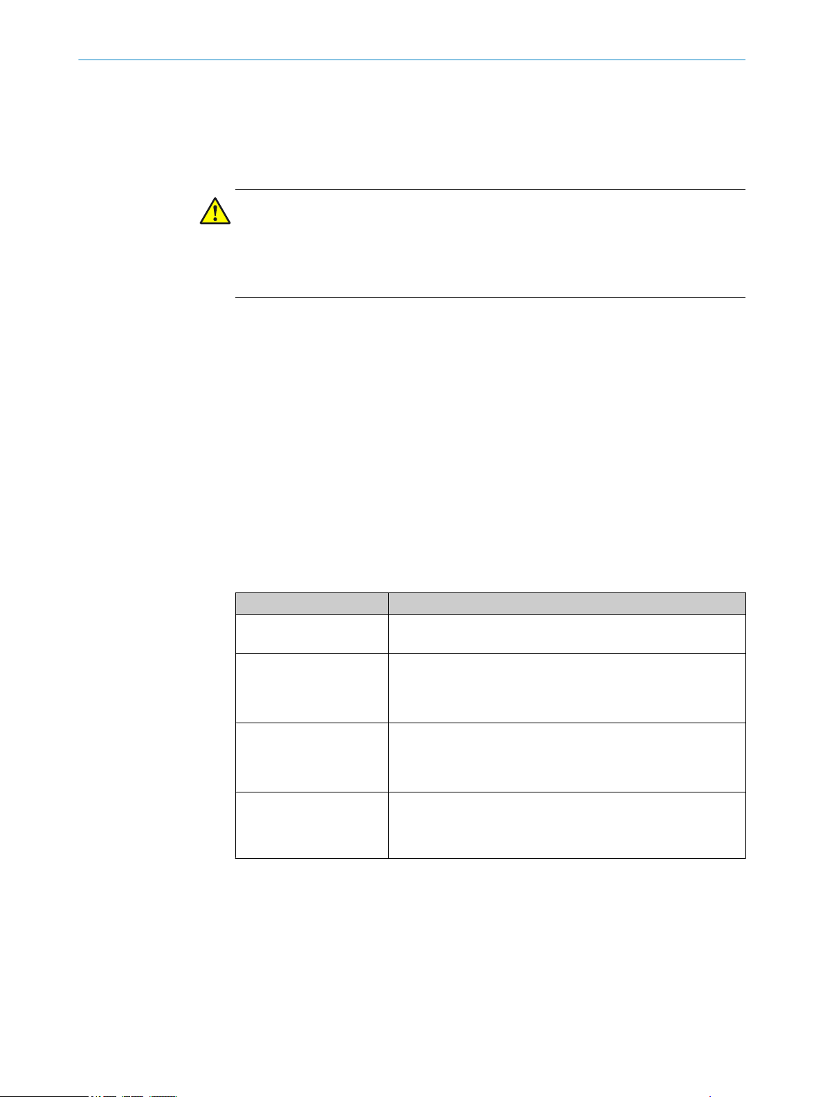
The following qualifications are required for various activities:
Table 1: Activities and technical requirements
Activities Qualification
Mounting, maintenance
Electrical installation,
device replacement
Commissioning, configura‐
tion
Operation of the device for
the particular application
Basic practical technical training
■
Knowledge of the current safety regulations in the workplace
■
Practical electrical training
■
Knowledge of current electrical safety regulations
■
Knowledge of the operation and control of the devices in their
■
particular application
Basic knowledge of the WindowsTM operating system in use
■
Basic knowledge of the design and setup of the described con‐
■
nections and interfaces
Basic knowledge of data transmission
■
Knowledge of the operation and control of the devices in their
■
particular application
Knowledge of the software and hardware environment for the
■
particular application
2.6 Operational safety and particular hazards
Please observe the safety notes and the warnings listed here and in other chapters of
these operating instructions to reduce the possibility of risks to health and avoid dan‐
gerous situations.
8
O PE R AT I NG IN S TR U CT I ON S | TiM1xx 8020631/11QG/2018-12-05 | SICK
Subject to change without notice
Page 9

SAFETY INFORMATION 2
CAUTION
Optical radiation: Laser class 1
The accessible radiation does not pose a danger when viewed directly for up to 100
seconds. It may pose a danger to the eyes and skin in the event of incorrect use.
■
Do not open the housing. Opening the housing may increase the level of risk.
■
Current national regulations regarding laser protection must be observed.
WARNING
Electrical voltage!
Electrical voltage can cause severe injury or death.
■
Work on electrical systems must only be performed by qualified electricians.
■
The power supply must be disconnected when attaching and detaching electrical
connections.
■
The product must only be connected to a voltage supply as set out in the require‐
ments in the operating instructions.
■
National and regional regulations must be complied with.
■
Safety requirements relating to work on electrical systems must be complied with.
8020631/11QG/2018-12-05 | SICK OP E RA T IN G I N ST R UC T IO N S | TiM1xx
Subject to change without notice
9
Page 10
3 PRODUCT DESCRIPTION
3 Product description
3.1 Product characteristics
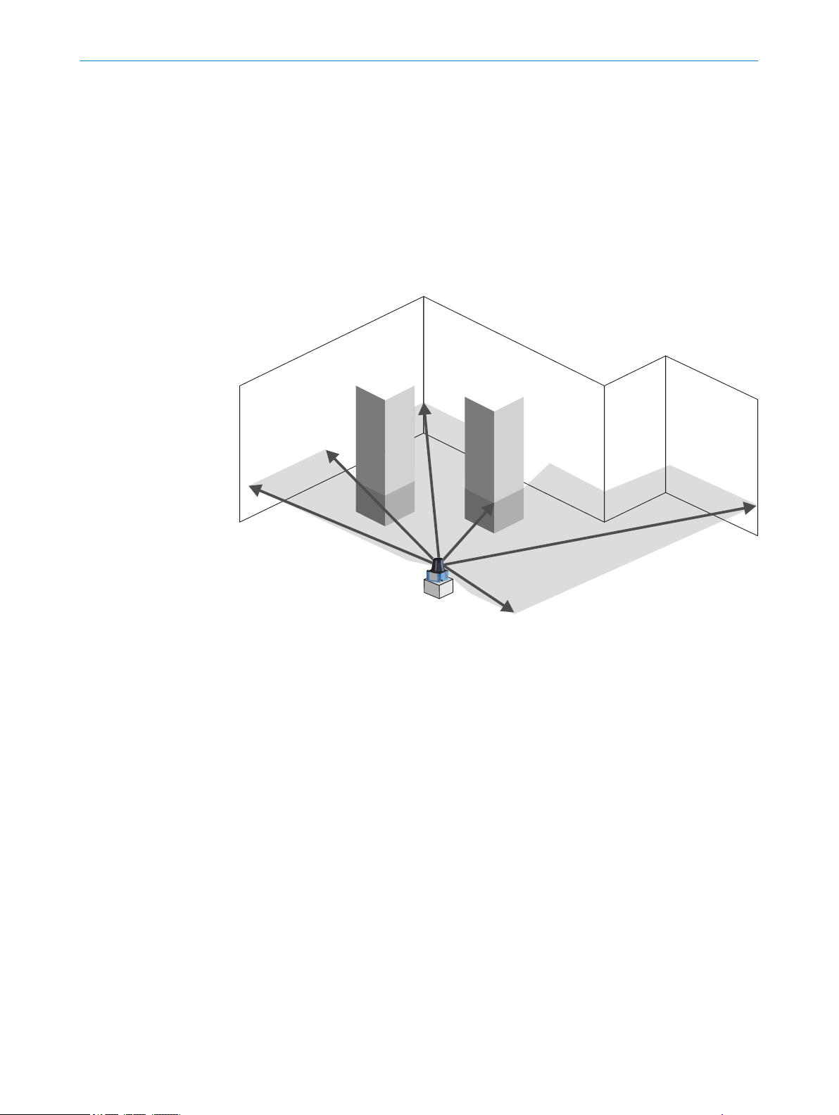
Measurement principle
The device is an opto-electronic LiDAR sensor that uses laser beams for non-contact
scanning of the outline of its surroundings on a plane. The device measures its sur‐
roundings in two-dimensional polar coordinates, relative to its measurement origin. Its
measurement origin is marked by a circular indentation in the center of the optics
cover. If a laser beam strikes an object, the position of that object is determined in
terms of distance and direction.
Figure 1: The 2D LiDAR sensor measurement principle
Range finding
The device emits beams pulsed by a laser diode. If a laser pulse hits an object or per‐
son, it is reflected on the surface of the object or person in question. The reflection is
registered by a photosensitive element in the device receiver. The device uses SICK’s
own HDDM+ (High Definition Distance Measurement plus) technology. With this mea‐
surement process, a measured value is formed by evaluating multiple single pulses.
The device calculates the distance from the object based on the elapsed time that the
light requires between emitting the beam and receiving the reflection. Radar systems
apply this “pulse time-of-flight measurement” principle in a similar way.
Direction measurement
The device uses a rotating mirror to deflect the emitted laser beams, thereby scanning
its surroundings in a circular pattern. The measurements are triggered internally by an
encoder in regular angle increments. The device has a scanning frequency of 14.5 Hz.
The measuring procedure uses a histogram of multiple pulses to determine individual
measured values.
10
O PE R AT I NG IN S TR U CT I ON S | TiM1xx 8020631/11QG/2018-12-05 | SICK
Subject to change without notice
Page 11

1
2
1
0
60
120
180
240
300
0 2000 3000 5000 70004000 6000
900080001000 10000
Range (mm)
Spot diameter (mm)
Spot diameter of a submeasuring point.
Divergence 9 mrad, spot diameter on the front screen 6 mm
Elongation of the overlayed submeasuring points in direction of deflection
at angle step 1°.
Divergence 26.5 mrad, spot diameter on the front screen 6 mm
2
PRODUCT DESCRIPTION 3
Device
Laser pulse
8020631/11QG/2018-12-05 | SICK OP E RA T IN G I N ST R UC T IO N S | TiM1xx
Subject to change without notice
11
Page 12

3
4
2
5
8
7
‒100°
90°
–90°
0°
à
ß
1
9
44.4 (
1.75)
47.7 (
1.88
)
18.1
(
0.71
)
75.8
(2.98)
27.3
(
1.07
)
8 (
0.31
)
53 (
2.09
)
Repair warranty
void if broken
59.6 (
2.35
)
7 (
0.28
)
76.6 (
3.02
)
M3
4 (
0.16
)
6.2 (
0.24
)
1
2
3
4
5
30°
200°
100°
1
6
30
(
1.18
)
59.6 (
2.35
)
60 (
2.36
)
3 PRODUCT DESCRIPTION
3.2 Setup and dimensions
Figure 2: Setup and dimensions TiM1xx
M3 threaded mounting hole, 2.8 mm deep (blind hole thread), tightening torque 0.8 Nm
1
2
3
4
5
6
7
8
9
ß
à
Optics cover
Receiving range (light inlet)
Transmission range (light emission)
Green LED
Red LED
Marking for the position of the light emission level
5-pin M12 male connector, rotatable
Area in which no reflective surfaces are permitted when the device is mounted
Bearing marking to support alignment (0° axis)
200° aperture angle (visual range)
12
O PE R AT I NG IN S TR U CT I ON S | TiM1xx 8020631/11QG/2018-12-05 | SICK
Subject to change without notice
Page 13

3.3 Status indicators
1 2
1
2
3
4
6
7
8
TIM100-3010200
2.2W
5.2W
6
5
Status indicators
Figure 3: Status indicators
1
2
PRODUCT DESCRIPTION 3
Green LED
Red LED
LED (green) LED (red) Description
O
O O
Light pattern: 1x long,
Light pattern depending on
- - Device without supply voltage
- Device ready/monitoring mode
Field breach (if there are lots of field
breaches in a short space of time,
the red LED lighting up might look
like flashing)
Ö
1x short
O orÖ
error cause
Service mode (e.g., firmware update,
device diagnostics, parameter config‐
uration)
Error, details see "Errors", page 25
3.4 Product ID
8020631/11QG/2018-12-05 | SICK OP E RA T IN G I N ST R UC T IO N S | TiM1xx
Subject to change without notice
O = illuminated; Ö = flashing
Type label
The following information can be read from the type label on the device:
Figure 4: TiM1xx type label (example)
Type designation
1
Part number
2
Serial number
3
Electrical connections
4
MAC address
5
Conformity mark/certification mark
6
7
Production date
13
Page 14

3 PRODUCT DESCRIPTION
8
QR code with part number and serial number
14
O PE R AT I NG IN S TR U CT I ON S | TiM1xx 8020631/11QG/2018-12-05 | SICK
Subject to change without notice
Page 15

4 Transport and storage
4.1 Transport
For your own safety, please read and observe the following notes:
NOTICE
Damage to the product due to improper transport.
■
The device must be packaged for transport with protection against shock and
damp.
■
Recommendation: Use the original packaging as it provides the best protection.
■
Transport should be performed by trained specialist staff only.
■
The utmost care and attention is required at all times during unloading and trans‐
portation on company premises.
■
Note the symbols on the packaging.
■
Do not remove packaging until immediately before you start mounting.
TRANSPORT AND STORAGE 4
4.2
Unpacking
■
Before unpacking, it may be necessary to equalize the temperature to protect the
device from condensation.
■
Handle the device with care and protect it from mechanical damage.
4.3 Transport inspection
Immediately upon receipt in Goods-in, check the delivery for completeness and for any
damage that may have occurred in transit. In the case of transit damage that is visible
externally, proceed as follows:
■
Do not accept the delivery or only do so conditionally.
■
Note the scope of damage on the transport documents or on the transport com‐
pany's delivery note.
■
File a complaint.
NOTE
Complaints regarding defects should be filed as soon as these are detected. Damage
claims are only valid before the applicable complaint deadlines.
4.4 Storage
Store the device under the following conditions:
■
Recommendation: Use the original packaging.
■
Do not store outdoors.
■
Store in a dry area that is protected from dust.
■
So that any residual damp can evaporate, do not package in airtight containers.
■
Do not expose to any aggressive substances.
■
Protect from sunlight.
■
Avoid mechanical shocks.
■
Storage temperature: see "Technical data", page 27.
■
Relative humidity: see "Technical data", page 27.
■
For storage periods of longer than 3 months, check the general condition of all
components and packaging on a regular basis.
8020631/11QG/2018-12-05 | SICK OP E RA T IN G I N ST R UC T IO N S | TiM1xx
Subject to change without notice
15
Page 16

5 MOUNTING
5 Mounting
5.1 Mounting instructions
Observe the technical data.
•
Protect the sensor from direct and indirect sunlight.
•
To prevent condensation, avoid exposing the device to rapid changes in tempera‐
•
ture.
The mounting site has to be designed for the weight of the device.
•
The device can be mounted in any position.
•
It should be mounted so that it is exposed to as little shock and vibration as possi‐
•
ble. Optional mounting accessories are available, see "Accessories", page 29.
During mounting, make sure there is no reflective surface behind the reference
•
target, see "Setup and dimensions", page 12.
To avoid inaccurate measurements when installing multiple devices: Make sure
•
that the laser spot of one device is not in the visible range of another device, see
"Mounting multiple devices", page 16.
Avoid having shiny or reflective surfaces in the scanning range, e.g., stainless
•
steel, aluminum, glass, reflectors, or surfaces with these types of coatings.
Protect the device from moisture, contamination, and damage.
•
Make sure that the status indicator is clearly visible.
•
Do not subject the device to excessive shock or vibrations. In systems subjected to
•
heavy vibrations, secure the fixing screws with screw-locking devices.
5.2 Mounting device
1. Mount the LiDAR sensor using the designated fixing holes, see "Setup and dimen‐
sions", page 12.
2. Make the electrical connection. Attach and tighten a voltage-free cable, see "Elec‐
trical connection of the sensor", page 17.
3. Switch on the supply voltage.
✓
The green operating LED lights up.
4. Align the vertical center line of the field of view of the device with the center of the
area to be monitored. The marking on the upper side of the optics cover serves as
a bearing alignment aid.
5.3 Mounting multiple devices
The device has been designed to minimize the probability of mutual interference with
devices of the same type. To rule out even the slightest effects on the measurement
accuracy, the devices should be arranged such the laser beams are not received by
another device.
16
O PE R AT I NG IN S TR U CT I ON S | TiM1xx 8020631/11QG/2018-12-05 | SICK
Subject to change without notice
Page 17

6 Electrical installation
1
2
4
3
5
L+
1
brn
M
3
blu
IO-Link/Q1
4
blk
reserved
2
wht
In/MF
5
gra
L+
1
brn
M
3
blu
IO-Link/Q1
4
blk
Q2
2
wht
In/MF
5
gra
6.1 Safety
WARNING
Personal injury due to incorrect supply voltage.
An incorrect supply voltage may result in personal injury.
■
Only operate the device using safety extra-low voltage and safe electrical insula‐
tion as per protection class III.
NOTICE
Equipment damage or unpredictable operation due to working with live parts.
Working with live parts may result in unpredictable operation.
■
Only carry out wiring work when the power is off.
■
Only connect and disconnect electrical connections when the power is off.
6.2 Electrical connection of the sensor
ELECTRICAL INSTALLATION 6
NOTICE
All electrical circuits must be connected to the device with safety extra-low voltage
(SELV or PELV).
Protect the device with an external 0.8 A slow-blow fuse at the beginning of the supply
cable.
1. Ensure that the voltage supply is not connected.
2. Connect the device as shown in the connection diagram and electrical block dia‐
grams.
Figure 5: Connection diagram TiM10x, 5-pin
male connector
Figure 6: Connection diagram TiM15x, 5-pin
male connector
Table 2: Legend for connection diagram
Contact Identification Wire color Description
1 L+ Brown Supply voltage V
2 TiM10x: -
TiM15x: Q
8020631/11QG/2018-12-05 | SICK OP E RA T IN G I N ST R UC T IO N S | TiM1xx
Subject to change without notice
3 M Blue Supply voltage GND
4 IO-Link/Q
2
1
White TiM10x: reserved
TiM15x: switching output 2
Black IO-Link/switching output 1
S
17
Page 18

SOPASSOPAS
„USB 2.0“
USBUSB
TiM1xx
„DC 24 V“
SiLink2
Master
TiM1xx
IO-Link
Master
TiM1xx
Connection box
V
s
customer-
provided
delayaction
fuse
0.8A/T
6 ELECTRICAL INSTALLATION
Contact Identification Wire color Description
5 In/MF Gray Input/multifunctional input
Electrical block diagrams
Figure 7: Electrical block diagram for configuration with SiLink2 Master
Figure 8: Electrical block diagram for configuration and operation with IO-Link Master
NOTICE
If the max. current of the IO-Link Master is not limited to 1 A: Protect the device with an
external 0.8 A slow-blow fuse.
Figure 9: Electrical block diagram for operation with direct connection
Switching output PNP or NPN
NOTICE
With NPN wiring, the switching output is already activated during the device initialization
phase.
18
O PE R AT I NG IN S TR U CT I ON S | TiM1xx 8020631/11QG/2018-12-05 | SICK
Subject to change without notice
Page 19

+
-
PNP
+
-
NPN
Figure 10: Connection example switching output
ELECTRICAL INSTALLATION 6
8020631/11QG/2018-12-05 | SICK OP E RA T IN G I N ST R UC T IO N S | TiM1xx
Subject to change without notice
19
Page 20

OPERATION
7
7 Operation
7.1 Operation via SOPAS ET
Version 3.3.3 and higher of the SOPAS Engineering Tool (SOPAS ET) software can be
used to parameterization of the device and for service and diagnostic purposes.
The following are needed to parameterization of the device parameters using a com‐
puter:
– A computer with SOPAS ET installed and a free USB2.0-compatible port
– SICK SiLink2 Master (Order No. 1061790)
– Connection cable with M12 male and female connectors, 5-pin (e.g. Order No.
2096006)
Use the connection cable to connect the device to the SiLink2 Master and use the wall
plug supplied to connect the SiLink2 Master to the power network. Use the USB cable
supplied with the SiLink2 Master to connect it to the computer.
NOTE
The most up-to-date version of the SOPAS ET software can be downloaded from
www.sick.com/SOPAS_ET. The respective system requirements for installing SOPAS ET
are also specified there.
NOTE
To use SOPAS ET with the device, you need a device description file (SDD) for this
device. You can install this within SOPAS ET using the device catalog. An Internet con‐
nection is required to install the SDD file.
Following installation of the device description file, the device can be selected from the
device catalog and added to a project.
A connection to the device is established via the IO-Link communication interface. The
connection must be activated for data transmission (online).
Information about the device is displayed in the device window and the device can also
be configured here (Device> Open menu).
20
O PE R AT I NG IN S TR U CT I ON S | TiM1xx 8020631/11QG/2018-12-05 | SICK
Subject to change without notice
Page 21

OPERATION
The device window features various views supporting a selection of functions:
Start: Display of information about the device (left-hand side) and display of the
•
current scan (right-hand side).
The scan view can be customized with the assistance of various tools (to the left of
the scan view).
Defaults: Device parameters can be configured, available parameter depends on
•
the device type.
7
Field evaluation: Scan display for adapting the field geometry (left-hand side) and
•
entering detection parameters (right-hand side):
8020631/11QG/2018-12-05 | SICK OP E RA T IN G I N ST R UC T IO N S | TiM1xx
Subject to change without notice
21
Page 22

7 OPERATION
The Edit field points tool (mouse pointer in the list of tools to the left of the scan
view) can be used to customize the field geometry with the assistance of the
mouse pointer. Alternatively, the field vertices can also be customized by entering
the coordinate values in the Field coordinates mask.
Table 3: Options for editing the field geometry with the mouse pointer
Function Procedure
Scale field Drag square red handle.
Rotate field Drag round black handle.
Customize field shape Drag square green handle.
Add field vertices Double-click in required position.
Delete field vertices Click to select square green handle and press the [del] key.
Delete field Press the [del] key without first selecting a green handle.
Insert new field Select the Insert field points tool, click to set field vertices, and
double-click last field vertex to close the field.
Complete: Scan display (left-hand side) and buttons to finalize the device parame‐
•
terization, report display and system diagnostics (right-hand side of the Configura‐
tion tab), along with text boxes to describe the configuration (right-hand side of the
Description tab).
NOTE
Changes to parameters that are made in SOPAS ET are not saved automatically in
the device. After you have completed the configuration, you must save it in the
device permanently by pressing the Save permanently button.
7.2 Operation via IO-Link
The device can exchange process data and parameters via IO-Link. To do this, it is con‐
nected to a suitable IO-Link Master.
The IO-Link interface of the device has the following properties:
Table 4: Properties of the IO-Link interface
IO-Link specification V 1.1
Minimum cycle time 2.3 ms
Transmission rate COM3 (230.4 kBaud)
Process data width 16-bit outgoing (from the sensor to the master)
Process data type UINT (unsigned integer)
22
O PE R AT I NG IN S TR U CT I ON S | TiM1xx 8020631/11QG/2018-12-05 | SICK
Subject to change without notice
Page 23

OPERATION 7
7.2.1 Process data
Parameter configuration server function (data
storage)
Process data format TiM10x:
Reserved2 (8 bits) + device status (4 bits) + reserved1 (3 bits) + output Q1 (1 bit)
•
Process data format TiM15x:
Reserved2 (8 bits) + device status (4 bits) + reserved1 (2 bits) + output Q2 (1 bit)
•
+ output Q1 (1 bit)
Numeric values for device status:
0 = Unknown State
•
1 = Start Up
•
2 = Service Mode
•
3 = Normal Operation
•
4 = Suspended Operation
•
5 = Service Recommended
•
6 = Service Required
•
7 = Recoverable Error
•
8 = Fatal Error
•
Yes
7.2.2 Device data
In addition to the process data, device data (parameters, identification data, and diag‐
nostic information) can be transmitted to and from the device. To use this function, a
sensor-specific device description file (IODD) is needed in the IO-Link Master.
A download package with the IODD and supplementary documentation (no. 8021043,
German/English) is available at www.sick.com/TiM1xx.
8020631/11QG/2018-12-05 | SICK OP E RA T IN G I N ST R UC T IO N S | TiM1xx
Subject to change without notice
23
Page 24

8 MAINTENANCE
8 Maintenance
8.1 Cleaning
NOTICE
Equipment damage due to improper cleaning.
Improper cleaning may result in equipment damage.
■
■
b
8.2 Maintenance
The product does not require regular maintenance.
Only use recommended cleaning agents.
Never use sharp objects for cleaning.
Clean the optics hood at regular intervals and in the event of contamination using
a lint-free lens cloth (part no. 4003353) and plastic cleaning agent (part no.
5600006). Rinse off coarse dirt first with water. The cleaning interval essentially
depends on the ambient conditions.
24
O PE R AT I NG IN S TR U CT I ON S | TiM1xx 8020631/11QG/2018-12-05 | SICK
Subject to change without notice
Page 25

9 Troubleshooting
9.1 Errors
Possible errors and corrective actions are described in the table below for troubleshoot‐
ing. In the case of errors that cannot be rectified using the information below, please
contact the SICK Service department. To find your agency, see the back page of this
document.
NOTE
Before calling, make a note of all type label data such as type designation, serial num‐
ber, etc., to ensure faster assistance.
Errors are signaled by the red LED. The light pattern is determined by the cause of the
error. When an error is being displayed by the red LED, the green LED is always off.
Table 5: Flashing pattern of the red LED in the event of an error
LED light pattern (red) Cause of error/Rectification
1x long, 3x short Device function faulty: Check ambient conditions (temperature,
1x long, 5x short Contact Service, device is still operational
1x long, 7x short Contact Service, device is operational subject to restrictions
Long Device malfunction: Disconnect the device from the supply voltage
Short Contact Service
TROUBLESHOOTING 9
ambient light, vibration)
and restart. If malfunction persists: Contact Service.
9.2 Detecting and displaying errors
Error memory
The device has an error memory where its internal error states are recorded. The con‐
tent of the error memory is retained when the device is switched off and when the
“Restore Factory Settings” function is used.
The SOPAS ET software can be used to create a diagnostics report containing error
information (Complete view, Configuration tab, Start Diagnosis button).
9.3
Information for the service case
You should collect and write down the following device information ahead of time if you
need to contact the manufacturer's service department:
Information about the firmware version
•
Information about the hardware
•
Information about operating hours
•
The information can be called up in the SOPAS ET software (Completion view, Device Info
tab).
9.4 Returns
Do not dispatch devices to the SICK Service department without consultation.
b
The device must be sent in the original packaging or an equivalent padded pack‐
b
aging.
8020631/11QG/2018-12-05 | SICK OP E RA T IN G I N ST R UC T IO N S | TiM1xx
Subject to change without notice
25
Page 26

9 TROUBLESHOOTING
9.5 Repairs
9.6 Disposal
NOTE
To enable efficient processing and allow us to determine the cause quickly, please
include the following when making a return:
■
Details of the contact person
■
Description of the application
■
Description of the fault that occurred
Repair work on the device may only be performed by qualified and authorized person‐
nel from SICK AG. Interruptions or modifications to the device by the customer will inval‐
idate any warranty claims against SICK AG.
Any device which can no longer be used must be disposed of in an environmentally
friendly manner in accordance with the applicable country-specific waste disposal regu‐
lations. Do not dispose of the product along with household waste.
NOTICE
Danger to the environment due to improper disposal of the device.
Disposing of devices improperly may cause damage to the environment.
Therefore, observe the following information:
■
Always observe the valid regulations on environmental protection.
■
Separate the recyclable materials by type and place them in recycling containers.
26
O PE R AT I NG IN S TR U CT I ON S | TiM1xx 8020631/11QG/2018-12-05 | SICK
Subject to change without notice
Page 27

10 Technical data
0
Scanning range in m (ft)
–2
(–6.56)
2
(6.56)
–3
(–9.84)
3
(9.84)
–1
(–3.28)
1
(3.28)
Scanning range in m (ft)
–2
(–6.56)
2
(6.56)
0
Scanning range max. 3 m (9.84 ft)
Scanning range 1.2 m to 1.5 m (3.94 ft to 4.92 ft)
for objects with 10 % remission, dependent on the angle
4
(13.12)
–4
(–13.12)
–4
(–13.12)
4
(13.12)
200°
90°
–90°
100°
‒100°
0°
0
Reichweite in m
6
6
2
2
Reichweite in m
2 2 6
6
0
10
10
10
10
14
14
14
14
Reichweite max. 10 m
Reichweite 2,8 m bis 3 m für Objekte
mit 10 % Remission, abhängig vom Winkel
200°
90°
–90°
100°
‒100°
0°
NOTE
The relevant online data sheet for your product, including technical data, dimensional
drawing, and connection diagrams can be downloaded, saved, and printed from the
Internet:
www.sick.com/TiM1xx
•
10.1 Features
Device type TiM10x TiM15x
Light source Infrared (invisible; wavelength
Laser class 1, eye-safe (IEC 60825-1:2014)
Aperture angle 200°
Scanning frequency 14.5 Hz
Working range 0.05 m ... 3 m 0.05 m ... 10 m
Sensing range with 10%
remission
850 nm; pulse length 2.5 ns;
max. output power ≤500 mW)
At least 1.2 m across enter
aperture angle
1.5 m (0° axis)
TECHNICAL DATA 10
Infrared (invisible; wavelength
850 nm; pulse length 2.5 ns;
max. output power ≤1,500 mW)
at least 2.8 m across entire
aperture angle
3 m (0° axis)
10.2 Performance
8020631/11QG/2018-12-05 | SICK OP E RA T IN G I N ST R UC T IO N S | TiM1xx
Subject to change without notice
Sensing range diagram
Figure 11: Sensing range diagram TiM10x
Figure 12: Sensing range diagram TiM15x
Device type TiM10x TiM15x
Response time Typ. ≥ 70 ms
Detectable object shape Almost any
Systematic error ± 50 mm
1
± 40 mm
1
27
Page 28

10 TECHNICAL DATA
10.3 Interfaces
Device type TiM10x TiM15x
Statistical error 20 mm
1
30 mm
Integrated application Field evaluation
Number of field sets 1 field set
Simultaneous analysis
1 (1 field) 1 (2 fields)
cases
1
Typical value; actual value depends on ambient conditions
Device type TiM10x TiM15x
IO-Link Function: AUX, configuration
Switching inputs 1
Switching outputs 1 (push-pull: PNP/NPN,
≤ 100 mA, not electrically iso‐
lated from the supply voltage)
2 (2 x push-pull: PNP/NPN, each
≤ 100 mA, not electrically iso‐
lated from the supply voltage)
Delay time 70 ms ... 30,000 ms (programmable)
Dwell time 70 ms ... 10,000 ms (programmable)
Optical indicators 2 LEDs (green, red)
1
10.4 Mechanics/electronics
Device type TiM10x TiM15x
Supply voltage 9 V DC ... 28 V DC 10 V DC ... 28 V DC
Power consumption Typ. 2.2 W, max. 5.2 W Typ. 2.7 W, max. 8.5 W
Enclosure rating IP 65 (IEC 60529:1989+AMD1:1999+AMD2:2013 )
Protection class III (IEC 61140:2016-01)
Weight 90 g, without connecting cables 122 g, without connecting
Dimensions (L x W x H) see "Setup and dimensions", page 12
10.5 Ambient data
Device type TiM10x TiM15x
Electromagnetic compati‐
bility (EMC)
Vibration resistance IEC 60068-2-6:2007
Shock resistance IEC 60068-2-27:2008
Ambient operating temper‐
ature
Storage temperature -30 °C ... +70 °C
Ambient light immunity Indirect: 80,000 lx Indirect: 30,000 lx
cables
IEC 61000-6-3:2007-01 / IEC 61000-6-2:2005-08 /
IEC 61000-6-1:2007-10
-10 °C ... +50 °C
28
O PE R AT I NG IN S TR U CT I ON S | TiM1xx 8020631/11QG/2018-12-05 | SICK
Subject to change without notice
Page 29

11 Accessories
NOTE
Accessories and where applicable mounting information can be found online at:
•
ACCESSORIES 11
www.sick.com/TiM1xx
8020631/11QG/2018-12-05 | SICK OP E RA T IN G I N ST R UC T IO N S | TiM1xx
Subject to change without notice
29
Page 30

12 ANNEX
12 Annex
12.1 EU declaration of conformity / Certificates
The EU declaration of conformity and other certificates can be downloaded from the
Internet at:
www.sick.com/TiM1xx
•
12.2 Licenses
SICK uses open-source software. This software is licensed by the rights holders using
the following licenses among others: the free licenses GNU General Public License (GPL
Version2, GPL Version3) and GNU Lesser General Public License (LGPL), the MIT
license, zLib license, and the licenses derived from the BSD license.
This program is provided for general use, but WITHOUT ANY WARRANTY OF ANY KIND.
This warranty disclaimer also extends to the implicit assurance of marketability or suit‐
ability of the program for a particular purpose.
More details can be found in the GNU General Public License. View the complete
license texts here: www.sick.com/licensetexts. Printed copies of the license texts are
also available on request.
30
O PE R AT I NG IN S TR U CT I ON S | TiM1xx 8020631/11QG/2018-12-05 | SICK
Subject to change without notice
Page 31

ANNEX 12
8020631/11QG/2018-12-05 | SICK OP E RA T IN G I N ST R UC T IO N S | TiM1xx
Subject to change without notice
31
Page 32

Further locations at www.sick.com
Australia
Phone +61 (3) 9457 0600
1800 33 48 02 – tollfree
E-Mail sales@sick.com.au
Austria
Phone +43 (0) 2236 62288-0
E-Mail office@sick.at
Belgium/Luxembourg
Phone +32 (0) 2 466 55 66
E-Mail info@sick.be
Brazil
Phone +55 11 3215-4900
E-Mail comercial@sick.com.br
Canada
Phone +1 905.771.1444
E-Mail cs.canada@sick.com
Czech Republic
Phone +420 2 57 91 18 50
E-Mail sick@sick.cz
Chile
Phone +56 (2) 2274 7430
E-Mail chile@sick.com
China
Phone +86 20 2882 3600
E-Mail info.china@sick.net.cn
Denmark
Phone +45 45 82 64 00
E-Mail sick@sick.dk
Finland
Phone +358-9-25 15 800
E-Mail sick@sick.fi
France
Phone +33 1 64 62 35 00
E-Mail info@sick.fr
Germany
Phone +49 (0) 2 11 53 01
E-Mail info@sick.de
Hong Kong
Phone +852 2153 6300
E-Mail ghk@sick.com.hk
Hungary
Phone +36 1 371 2680
E-Mail ertekesites@sick.hu
India
Phone +91-22-6119 8900
E-Mail info@sick-india.com
Israel
Phone +972-4-6881000
E-Mail info@sick-sensors.com
Italy
Phone +39 02 27 43 41
E-Mail info@sick.it
Japan
Phone +81 3 5309 2112
E-Mail support@sick.jp
Malaysia
Phone +603-8080 7425
E-Mail enquiry.my@sick.com
Mexico
Phone +52 (472) 748 9451
E-Mail mario.garcia@sick.com
Netherlands
Phone +31 (0) 30 229 25 44
E-Mail info@sick.nl
New Zealand
Phone +64 9 415 0459
0800 222 278 – tollfree
E-Mail sales@sick.co.nz
Norway
Phone +47 67 81 50 00
E-Mail sick@sick.no
Poland
Phone +48 22 539 41 00
E-Mail info@sick.pl
Romania
Phone +40 356-17 11 20
E-Mail office@sick.ro
Russia
Phone +7 495 283 09 90
E-Mail info@sick.ru
Singapore
Phone +65 6744 3732
E-Mail sales.gsg@sick.com
Slovakia
Phone +421 482 901 201
E-Mail mail@sick-sk.sk
Slovenia
Phone +386 591 78849
E-Mail office@sick.si
South Africa
Phone +27 (0)11 472 3733
E-Mail info@sickautomation.co.za
South Korea
Phone +82 2 786 6321
E-Mail info@sickkorea.net
Spain
Phone +34 93 480 31 00
E-Mail info@sick.es
Sweden
Phone +46 10 110 10 00
E-Mail info@sick.se
Switzerland
Phone +41 41 619 29 39
E-Mail contact@sick.ch
Taiwan
Phone +886-2-2375-6288
E-Mail sales@sick.com.tw
Thailand
Phone +66 2 645 0009
E-Mail marcom.th@sick.com
Turkey
Phone +90 (216) 528 50 00
E-Mail info@sick.com.tr
United Arab Emirates
Phone +971 (0) 4 88 65 878
E-Mail info@sick.ae
United Kingdom
Phone +44 (0)17278 31121
E-Mail info@sick.co.uk
USA
Phone +1 800.325.7425
E-Mail info@sick.com
Vietnam
Phone +65 6744 3732
E-Mail sales.gsg@sick.com
8020631/11QG/2018-12-05/en
SICK AG | Waldkirch | Germany | www.sick.com
 Loading...