

Page 1
T-EASIC® FTS
Flow sensor
OPERATING INSTRUCTIONS
en
Page 2

Product described
®
T-Easic
Manufacturer
SICK AG
Erwin-Sick-Str. 1
79183 Waldkirch
Germany
Legal notes
This work is protected by copyright. The associated rights are reserved by SICK AG. Reproduction of this document
or parts of this document is only permissible within the limits of the legal provisions of copyright law.
Any modication, abridgment, or translation of this document is prohibited without the express written permission
of SICK AG.
The trademarks mentioned in this document are the property of their respective owners.
© SICK AG. All rights reserved.
Original document
FTS
This document is an original document published by SICK AG.
2
OPERATING INSTRUCTIONS | T-EASIC® 8023072/ 2018-09-03 | SICK AG
Subject to change without notice
Page 3

Contents
1 About this document .......................................................................................6
1.1 Information on the operating instructions ................................................................ 6
1.2 Scope ..........................................................................................................................6
1.3 Explanation of symbols ..............................................................................................6
1.4 Further information ....................................................................................................7
1.5 Customer service ........................................................................................................7
2 Safety information ...........................................................................................8
2.1 Intended use ............................................................................................................... 8
2.2 Improper use...............................................................................................................8
2.3 Limitation of liability ................................................................................................... 8
2.4 Modications and conversions .................................................................................. 8
2.5 Requirements for skilled persons and operating personnel ...................................9
2.6 Operational safety and specic hazards .................................................................10
2.7 Use at high operating temperatures .......................................................................10
2.8 General safety notes ................................................................................................10
3 Product description ....................................................................................... 11
3.1 Product identication ...............................................................................................11
3.1.1 Information on the housing ......................................................................11
3.1.2 Type code ..................................................................................................11
3.2 Product characteristics ............................................................................................12
3.2.1 Device view ...............................................................................................12
3.2.2 Operating buttons (Industrial version only).............................................12
3.3 Product features and functions ...............................................................................13
3.3.1 Principle of operation ...............................................................................13
3.3.2 Fields of application .................................................................................13
4 Transport and storage .................................................................................. 14
4.1 Transport ...................................................................................................................14
4.2 Transport inspection ................................................................................................14
4.3 Storage ......................................................................................................................14
5 Mounting ......................................................................................................... 15
5.1 Installation conditions ..............................................................................................15
5.2 Probe alignment to the ow direction .....................................................................16
5.3 Mounting the sensor ................................................................................................17
5.4 Mounting the process connection adapter .............................................................17
5.5 Dismounting the process connection adapter .......................................................18
Subject to change without notice
6 Electrical installation .................................................................................... 19
6.1 Safety ........................................................................................................................19
6.1.1 Notes on the electrical installation ..........................................................19
6.2 Electrical connection ................................................................................................20
6.2.1 Overview of the electrical connections ...................................................20
OPERATING INSTRUCTIONS | T-EASIC® 8023072/2018-09-03| SICK AG
3
Page 4

6.2.2 Pin assignment, M12 plug connector, 4-pin ...........................................20
7 Commissioning .............................................................................................. 21
7.1 Quick commissioning (with factory settings) ..........................................................21
7.2 Operation ..................................................................................................................21
7.2.1 Display, LEDs and operating buttons (Industrial version only) ..............21
7.2.2 Information shown on the display (Industrial version only) ...................21
7.2.3 LEDs (Industrial version only) ..................................................................22
7.2.4 IO-Link .......................................................................................................22
7.3 Measurement conguration ....................................................................................22
7.3.1 Conguration of the Measurement Mode based on Volume absolute as
example 23
7.3.2 Conguration of the Measurement Mode based on Teach relative as
example 23
7.3.3 Conguration of Q1 and Q2 .....................................................................24
7.3.4 Conguration of the switching output Q1 and Q2 ..................................25
7.3.5 Normally open with congurable hysteresis ...........................................25
7.3.6 Normally closed with congurable hysteresis .........................................26
7.3.7 Normally open with window function ......................................................27
7.3.8 Normally closed with window function ....................................................28
7.3.9 Conguration of the digital input Q2 .......................................................29
7.4 Advanced menu (advanced settings) ......................................................................30
7.4.1 Unit Pipe Diameter ...................................................................................32
7.4.2 Unit Velocity ..............................................................................................32
7.4.3 Unit Volume ...............................................................................................32
7.4.4 Unit Temperature ......................................................................................32
7.4.5 Filter (process data) .................................................................................32
7.4.6 Linear Flow Factor ....................................................................................33
7.4.7 Delay Mode Q1 .........................................................................................33
7.4.8 Delay Time Q1 ...........................................................................................35
7.4.9 Delay Mode Q2 .........................................................................................35
7.4.10 Delay Time Q2 ...........................................................................................36
7.4.11 Simulation .................................................................................................36
7.4.12 Display Mode (Industrial version only) ....................................................36
7.4.13 Factory Reset ............................................................................................37
7.4.14 Display Lock (Industrial version only) ......................................................37
7.4.15 Password ...................................................................................................37
7.4.16 Advanced Menu (Close Menu) .................................................................37
7.5 Information ...............................................................................................................37
8 Troubleshooting ............................................................................................. 39
8.1 Error message on the display (Industrial version only) ..........................................39
8.2 Outputs......................................................................................................................40
9 Repair .............................................................................................................. 41
9.1 Maintenance .............................................................................................................41
9.2 Returns ......................................................................................................................41
4
OPERATING INSTRUCTIONS | T-EASIC® 8023072/ 2018-09-03 | SICK AG
Subject to change without notice
Page 5

10 Disposal .......................................................................................................... 42
11 Technical data ................................................................................................ 43
11.1 Features ....................................................................................................................43
11.2 Performance .............................................................................................................43
11.3 Mechanics/materials ...............................................................................................44
11.4 Ambient conditions ..................................................................................................44
11.5 Electrical connections ..............................................................................................45
12 Dimensional drawings .................................................................................. 46
12.1 Industrial version ......................................................................................................46
12.2 Hygenic version.........................................................................................................47
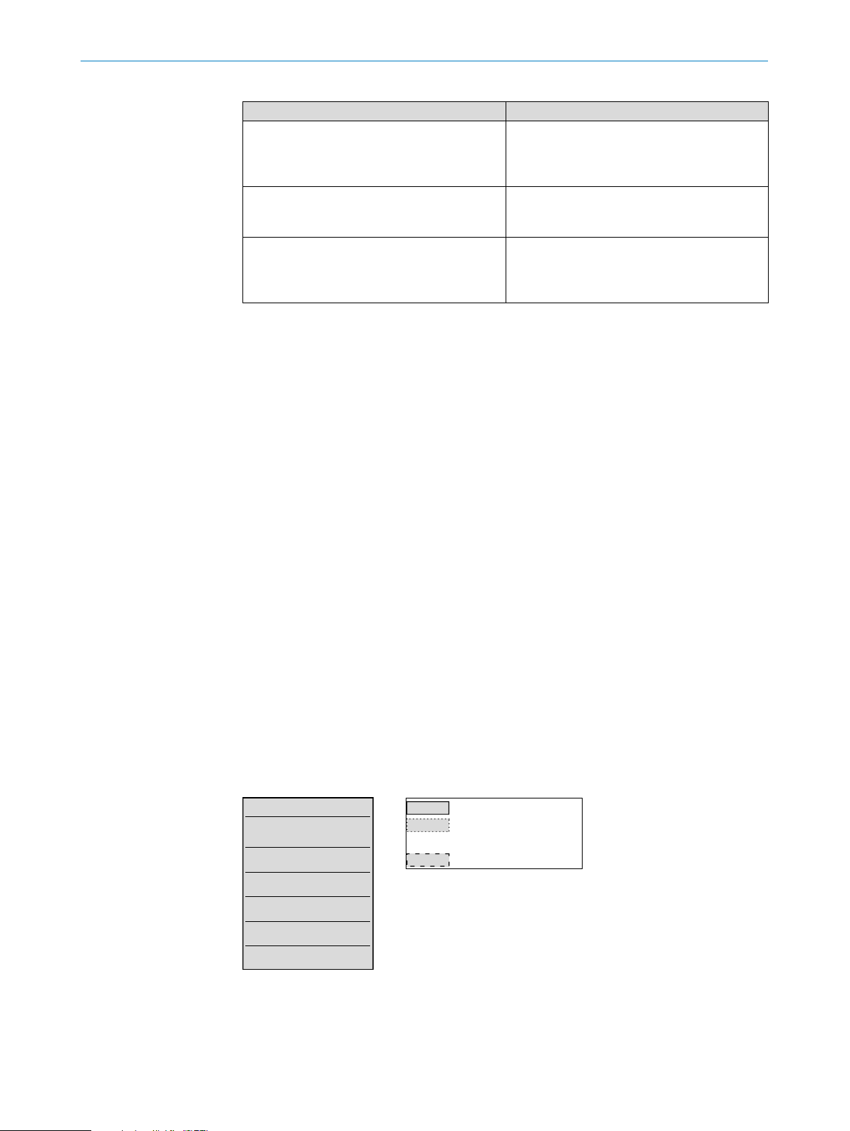
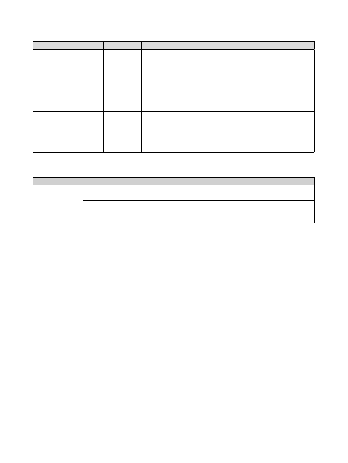
12.3 Mounting adapters for T-Easic® FTS ........................................................................47
12.3.1 Adapter G1/2 (p/n 5338774) .................................................................47
12.3.2 Adapter 1/2" NPT (p/n 5338775) ..........................................................48
12.3.3 Adapter M18 x 1.5 (p/n 2104208) .........................................................48
12.3.4 Adapter clamp DIN32676 DN25-40 (p/n 2093548) ............................49
13 Factory settings ............................................................................................. 50
14 Accessories .................................................................................................... 51
15 Menu overview ............................................................................................... 52
16 License text .................................................................................................... 54
Subject to change without notice
OPERATING INSTRUCTIONS | T-EASIC® 8023072/2018-09-03| SICK AG
5
Page 6
1 ABOUT THIS DOCUMENT
1 About this document
1.1 Information on the operating instructions
These operating instructions provide important information on how to use sensors from
SICK AG.
Prerequisites for safe work are:
• Compliance with all safety notes and handling instructions supplied.
• Compliance with local work safety regulations and general safety regulations for
sensor applications.
The operating instructions are intended to be used by qualied personnel and electrical
specialists.
Note:
Read these operating instructions carefully before starting any work on the device, in
order to familiarize yourself with the device and its functions.
The instructions must be kept in the immediate vicinity of the device so they remain
accessible to sta at all times. Should the device be passed on to a third party, these
operating instructions should be handed over with it.
These operating instructions do not provide information on operating any system in
which the sensor may be integrated. For information about this, refer to the operating
instructions of the particular system.
1.2 Scope
These operating instructions explain how to incorporate a sensor into a customer
system. Instructions are given in stages for all actions required.
These instructions apply to all available device versions of the sensor. For more detailed
information on identifying your device type, see “3.1.2 Type code”.
Available device versions are listed on the online product page:
b www.sick.com/T-Easic_FTS
A number of device versions are used as examples for commissioning, based on the
default parameter settings for the relevant device.
In this document, the T-Easic
form as T-Easic
between device versions due to dierent technical features or functions. In such cases,
the complete type designation is used.
1.3 Explanation of symbols
Warnings and important information in this document are labeled with symbols. The
warnings are introduced by signal words that indicate the extent of the danger. These
warnings must be observed at all times and care must be taken to avoid accidents,
personal injury, and material damage.
®
®
or FTS, except in cases where it is necessary to make a distinction
FTS (Flow Thermal Switch) is referred to in simplied
HAZARD
… indicates a situation of imminent danger, which will lead to a fatality or serious injuries if not prevented.
6
OPERATING INSTRUCTIONS | T-EASIC® 8023072/ 2018-09-03 | SICK AG
Subject to change without notice
Page 7
WARNING
… indicates a potentially dangerous situation, which may lead to a fatality or serious
injuries if not prevented.
CAUTION
… indicates a potentially dangerous situation, which may lead to minor/slight injuries if
not prevented.
IMPORTANT
… indicates a potentially harmful situation, which may lead to material damage if not
prevented.
NOTE
… highlights useful tips and recommendations as well as information for ecient and
trouble-free operation.
1ABOUT THIS DOCUMENT
1.4 Further information
NOTE
All the documentation available for the sensor can be found on the online product page
at:
www.sick.com
The following information is available for download from this page:
• Model-specic online data sheets for device versions, containing technical data,
dimensional drawings, and diagrams
• EU declaration of conformity for the product family
• Dimensional drawings and 3D CAD dimension models in various electronic formats
• These operating instructions, available in English and German, and in other languag-
es if necessary
• Other publications related to the sensors described here (e.g., IO-Link)
• Publications dealing with accessories
1.5 Customer service
If you require any technical information, our customer service department will be happy
to help. To nd your representative, see the nal page of this document.
NOTE
Subject to change without notice
Before calling, make a note of all sensor data such as type code, serial number, etc., to
ensure faster processing.
OPERATING INSTRUCTIONS | T-EASIC® 8023072/2018-09-03| SICK AG
7
Page 8

2 SAFETY INFORMATION
2 Safety information
2.1 Intended use
The T-Easic® is a ow sensor for liquids (dened in “11 Technical data”) that operates
on the basis of the calorimetric measurement principle. It converts the ow rate and
temperature of the medium into an electrical signal.
The information of the ow rate and the medium temperature of the liquid are shown
on the OLED display (industrial version only). The ow and temperature information is
available over IO-Link, too. Two switching outputs can be set for both ow and tempera-
ture control.
The sensor fullls the requirements of EN 61326-2-3 for industrial environments.
2.2 Improper use
This sensor does not constitute a safety component according to the EC Machinery
Directive (2006/42/EC).
The sensor must not be used in explosion-hazardous areas.
It is not permitted to open the T-Easic
Any use outside of the stated areas, in particular use outside of the technical specications and the requirements for intended use, will be deemed to be improper use.
®
housing.
If the equipment is used in a manner not specied by this document, the protection
provided by the equipment may be impaired.
If the sensor is to be used under other conditions or in dierent environments, the manufacturer’s service department may issue an operating license in consultation with the
customer and in exceptional cases.
2.3 Limitation of liability
Applicable standards and regulations, the latest technological developments and
our many years of knowledge and experience have all been taken into account when
assembling the data and information contained in these operating instructions. The
manufacturer accepts no liability for damage caused by:
• Failing to observe the operating instructions
• Improper use
• Use by untrained personnel
• Unauthorized conversions
• Technical modications
• Use of unauthorized spare parts, consumables, and accessories
With special versions, where optional extras have been ordered, or owing to the latest
technical changes, the actual scope of delivery may vary from the features and illustra-
tions shown here.
2.4 Modications and conversions
IMPORTANT
Modications and conversions to the sensor and/or the installation may result in unforeseeable dangers.
8
OPERATING INSTRUCTIONS | T-EASIC® 8023072/ 2018-09-03 | SICK AG
Subject to change without notice
Page 9
Interfering with or modifying the sensor or SICK software will invalidate any warranty
claims against SICK AG. This applies in particular to opening the housing, even as part
of mounting and electrical installation work.
Before making technical modications to or expanding the sensor, the prior written
approval of the manufacturer must be obtained.
Never install or connect accessories if their quantity and composition are not clearly
specied, or if they have not been approved by SICK AG.
2.5 Requirements for skilled persons and operating personnel
WARNING
Risk of injury due to insucient training.
Improper handling of the sensor may result in considerable personal injury and material
damage.
• All work must only ever be carried out by the stipulated persons.
The operating instructions state the following qualication requirements for the various
areas of work:
2SAFETY INFORMATION
• Instructed personnel have been briefed by the operating entity about the tasks
assigned to them and about potential dangers arising from improper action.
• Skilled personnel have the specialist training, skills, and experience, as well as
knowledge of the relevant regulations, to be able to perform tasks assigned to
them and to detect and avoid any potential dangers independently.
• Electricians have the specialist training, skills, and experience, as well as knowl-
edge of the relevant standards and provisions to be able to carry out work on
electrical systems and to detect and avoid any potential dangers independently.
In Germany, electricians must meet the specications of the BGV A3 Work Safety
Regulations (e.g., Master Electrician). Other relevant regulations applicable in other
countries must be observed.
The following qualications are required for various activities:
Activities Qualication
Mounting, maintenance
Electrical installation, de-
vice replacement
Commissioning,
conguration
Operation of the device for
the specic application
• Basic practical technical training
• Knowledge of the current safety regulations in the workplace
• Practical electrical training
• Knowledge of current electrical safety regulations
• Knowledge of device control and operation in the specic application concerned (e.g., conveying line)
• Basic knowledge of the control system used
• Basic knowledge of the design and setup of the described
connections and interfaces
• Basic knowledge of data transmission
• Knowledge of device control and operation in the specic application concerned (e.g., CIP/SIP system)
• Knowledge of the software and hardware environment for the
specic application concerned (e.g., CIP/SIP system)
Subject to change without notice
OPERATING INSTRUCTIONS | T-EASIC® 8023072/2018-09-03| SICK AG
9
Page 10
2 SAFETY INFORMATION
2.6 Operational safety and specic hazards
b Observe the safety notes and the warnings listed here and in other chapters of
these operating instructions to reduce the possibility of risks to health and avoid
dangerous situations.
2.7 Use at high operating temperatures
When the process temperature is above 50 °C, the sensor housing may get hot.
CAUTION
Risk of burning on sensor housing
• Only touch the hot housing if you are wearing safety gloves.
• Avoid contact of the sensor with ammable substances.
2.8 General safety notes
• Read the operating instructions prior to commissioning.
• These operating instructions are valid for devices from rmware version 1.20.
®
• The T-Easic
is not a safety component under the EU Machinery Directive.
• Observe national safety and work safety regulations.
• Wiring work and the opening and closing of electrical connections may only be
carried out when the power is switched o.
• The sensor must be not power supplied if not installed in the pipe system as described in “5 Mounting”.
• The radiated power is far lower than that from telecommunication equipment.
According to current scientic research, the operation of this device can be classied as safe and non-hazardous.
• The sensor has been designed according to the Pressure Equipment Directive
Article 3 Paragraph 3 according to good engineering practice.
10
OPERATING INSTRUCTIONS | T-EASIC® 8023072/ 2018-09-03 | SICK AG
Subject to change without notice
Page 11
3 Product description
3.1 Product identication
3.1.1 Information on the housing
Information for identication of the sensor (serial number, part number and type code)
and its electrical connection are printed on the label attached on the housing of the
sensor.
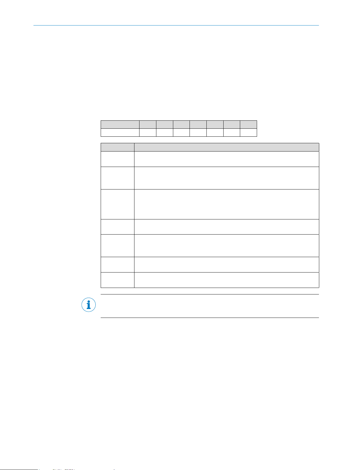
3.1.2 Type code
T-Easic® FTS - I 100 F 1 4 A
1 2 3 4 5 6 7
Position Description
1 Product group
2 Version
3 Probe length
4 Media
5 Display
6 Electrical connection
7 Electrical output
®
T-Easic
I: Industrial
H: Hygienic
060: 60 mm
100: 100 mm
200: 200 mm
F: Liquids
0: No
1: Yes (OLED + 3 status LED)
4: M12, 4-pin
A: 1 digital output + 1 digital input / output
FTS (ow sensors)
3PRODUCT DESCRIPTION
Subject to change without notice
NOTE
Not all versions of the type code can be combined!
OPERATING INSTRUCTIONS | T-EASIC® 8023072/2018-09-03| SICK AG
11
Page 12
3 PRODUCT DESCRIPTION
1
3
4
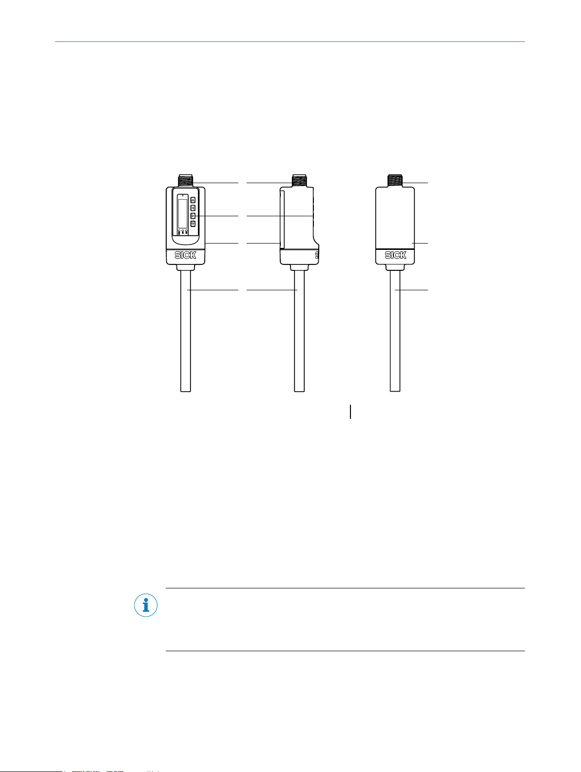
3.2 Product characteristics
3.2.1 Device view
®
The T-Easic
- Industrial version with display operating buttons and VISTAL
- Hygienic version in full stainless steel 1.4404 (316L) housing.
is available in two versions:
®
housing
1
1
2
3
4
Fig. 1: T-Easic® overview Industrial version Fig. 2: T-Easic® overview Hygienic version
3
4
1 M12 electrical connection
2 Display with operating buttons and LEDs
3 Housing
4 Measuring probe
3.2.2 Operating buttons (Industrial version only)
The sensor is operated using the display and the operating buttons (Industrial version
only).
For a detailed description of the buttons and their functions, see “7.2.1 Display, LEDs
and operating buttons (Industrial version only)”.
NOTE
Both versions of the T-Easic
Link 1.1 communication interface.
For IO-Link see “7.2.4 IO-Link”.
12
OPERATING INSTRUCTIONS | T-EASIC® 8023072/ 2018-09-03 | SICK AG
®
can be programmed with the SICK SOPAS-ET via the IO-
Subject to change without notice
Page 13

3.3 Product features and functions
3.3.1 Principle of operation
®
The T-Easic
aqueous media, oil, etc.).
The measurement method is based on the calorimetric principle. The sensor measures
the cooling eect of the owing liquid on the heated measuring probe. The higher the
ow velocity of the liquid, the higher the cooling eect of the heated probe.
The sensor has two congurable switching outputs (Q1 and Q2) for ow or temperature.
Q2 can be selected as digital input.
The switching output Q1 also features an IO-Link interface; see “7.2.4 IO-Link”.
3.3.2 Fields of application
The T-Easic
pumps, heat exchangers, leak monitoring for process lines, dry-run protection for
pumps, as well as monitoring of oil in hydraulic system and wind mill lubrication and
hydraulic circuits.
FTS (Flow Thermal Switch) monitors the ow velocity of liquids (i.e. water,
®
is especially suitable for measuring tasks regarding cooling water circuits,
3PRODUCT DESCRIPTION
Subject to change without notice
OPERATING INSTRUCTIONS | T-EASIC® 8023072/2018-09-03| SICK AG
13
Page 14
4 TRANSPORT AND STORAGE
4 Transport and storage
4.1 Transport
For your own safety, read and observe the following notes:
IMPORTANT
Damage to the sensor due to improper transport.
• The device must be packaged for transport with protection against shock and damp.
• Recommendation: Use the original packaging as it provides the best protection.
• Transport should be performed by specialist sta only.
• The utmost care and attention is required at all times during unloading and transpor-
tation on company premises.
• Note the symbols on the packaging.
• Do not remove packaging until immediately before starting installation work.
4.2 Transport inspection
Immediately upon receipt in goods-in, check the delivery for completeness and for any
damage that may have occurred in transit. In the case of transit damage that is visible
externally, proceed as follows:
4.3 Storage
• Do not accept the delivery or only do so conditionally.
• Note the scope of damage on the transport documents or on the transport company's delivery note.
• File a complaint.
Note:
Complaints regarding defects should be led as soon as these are detected. Damage
claims are only valid before the applicable complaint deadlines.
Store the device under the following conditions:
• Recommendation: Use the original packaging.
• Do not store outdoors.
• Store in a dry area that is protected from dust.
• Do not store in an airtight container: this is so that any residual moisture present
can escape.
• Do not expose to any aggressive substances.
• Protect from sunlight.
• Avoid mechanical shocks.
14
• Storage temperature: see “11 Technical data”.
• For storage periods of longer than 3 months, check the general condition of all
components and packaging on a regular basis.
OPERATING INSTRUCTIONS | T-EASIC® 8023072/ 2018-09-03 | SICK AG
Subject to change without notice
Page 15
5 Mounting
1
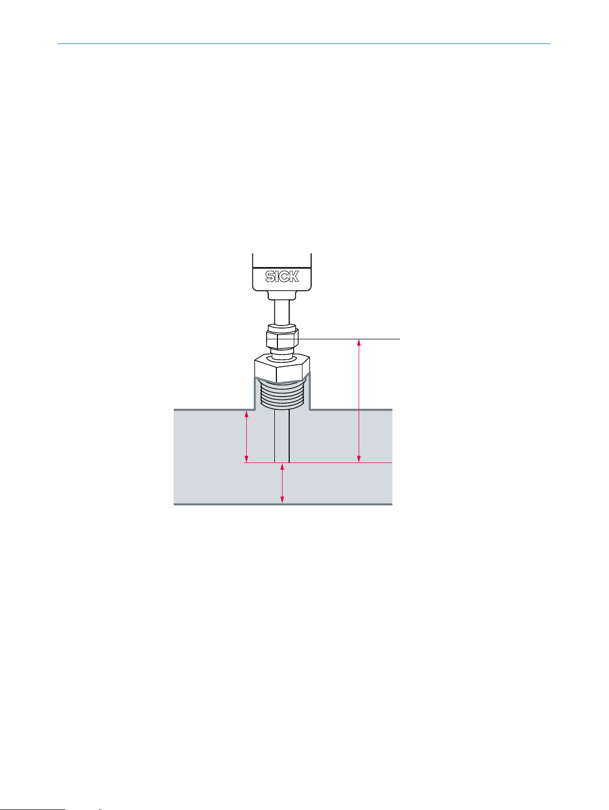
5.1 Installation conditions
When installing the sensor the system must be not pressurised and the pipe where the
sensor has to be installed must be empty.
The inserted probe must be always completely surrounded by the medium. A minimum
insertion depth of ≥ 12 mm should be observed.
The cutting ring of the process connection adapter must be ≥ 25 mm away from the
probe tip to avoid damage to the sensing element.
The sensor probe should be positioned in the centre of the pipe and it must not be in
contact with the pipe wall.
A minimum distance of ≥ 10 mm from the tip to the pipe wall must be observed.
5MOUNTING
2
3
4
Fig. 3: Minimum installations lengths
1 Cutting ring center line
2 ≥ 25 mm
3 ≥ 12 mm
4 ≥ 10 mm
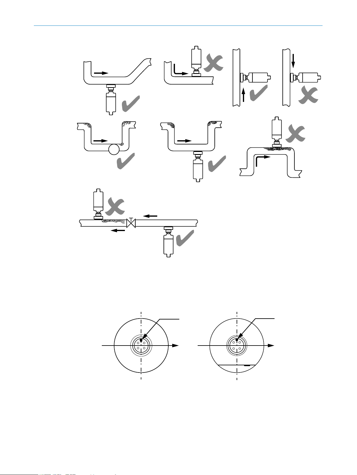
The sensor should be installed at least 5 ... 10xDN in front of and 3 ... 5xDN behind
valves, T-pieces, curves or cross-sectional alterations.
Installation in the standpipe is recommended for vertically installed pipes. The sensor
must not be mounted before or in a downpipe or in an open downpipe.
Horizontal mounting from the bottom is only possible if the pipe is free from build-up.
Subject to change without notice
OPERATING INSTRUCTIONS | T-EASIC® 8023072/2018-09-03| SICK AG
15
Page 16
5 MOUNTING
Fig. 4: Installation orientation
5.2 Probe alignment to the ow direction
For optimal accuracy performance make sure that the M12 coding key in the connector
is 90° angled with the ow direction.
Fig. 5: Orientation of the T-Easic® aligned with ow direction in Hygienic (left) and Industrial
(right) version
1 M12 coding key
2 Flow direction
1
2
1
2
16
OPERATING INSTRUCTIONS | T-EASIC® 8023072/ 2018-09-03 | SICK AG
Subject to change without notice
Page 17
5.3 Mounting the sensor
1. Stop the ow.
2. Depressurize the system.
3. Empty the pipe where the sensor has to be installed.
4. Install the process connection adapter on the sensor (see “5.4 Mounting the pro-
cess connection adapter”).
5. Seal the process connection to the pipe.
6. At the mounting point, screw the ow switch in hand-tight.
7. Tighten with a at spanner.
IMPORTANT
Leaking
• For sealing the process connection to the pipe the operating pressure must be considered while choosing the correct sealing method.
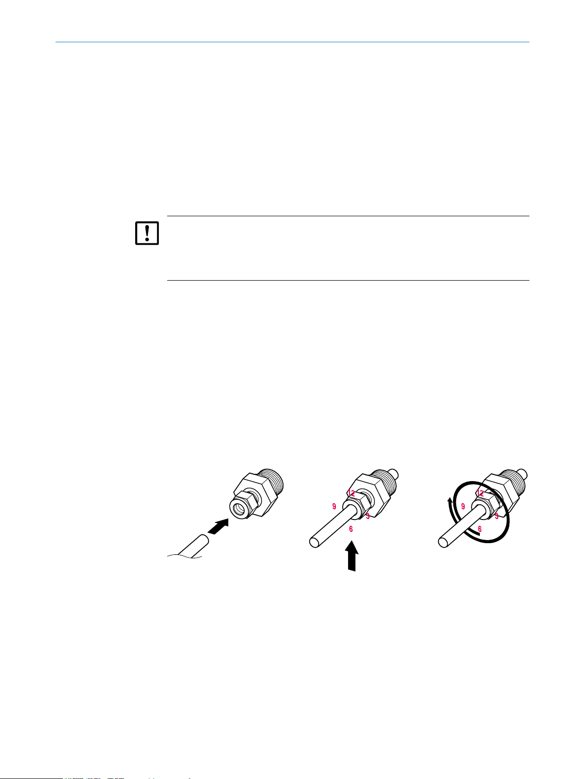
5.4 Mounting the process connection adapter
It is strictly recommended to use only original adapters from SICK. The adapters are not
included and have to be ordered separately.
5MOUNTING
See “14 Accessories” for more detailed information about the process connection
adapters.
1. Insert the probe of the sensor into the pipe tting.
2. Hand-tighten the union nut until the probe no longer turns by hand or can no lon-
ger be moved axially in the tting.
3. Mark the union nut at the 6 o'clock position.
4. Hold the tting body with a wrench and tighten the union nut to the 9 o'clock posi-
tion with 1 1/4 turns.
Fig. 6: Mounting the process connector adapter on the sensor probe
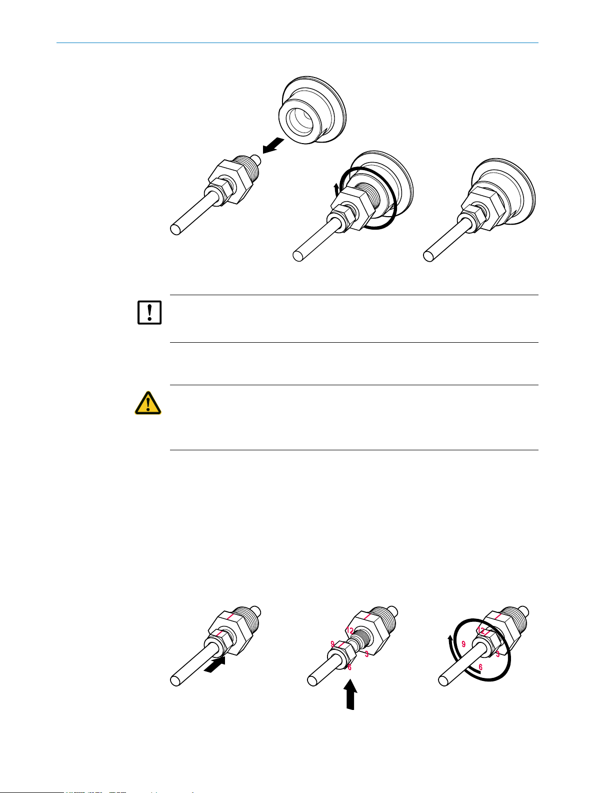
For a hygienic solution the adapter must be installed in the same way on the sensor
probe as described above and then assembled to the hygienic clamp adapter p/n
2093548.
Subject to change without notice
OPERATING INSTRUCTIONS | T-EASIC® 8023072/2018-09-03| SICK AG
17
Page 18
5 MOUNTING
Fig. 7: Mounting the process connector adapter on the hygienic clamp adapter
IMPORTANT
The FKM gasket, part of the clamp adapter p/n 2093548, must be chemically resistant
to the process medium.
5.5 Dismounting the process connection adapter
CAUTION
Pressure
Always depressurize the system, stop the ow and empty the pipe before dismounting
the sensor.
To dismount the process connection adapter from the probe of the sensor:
1. Before dismantling, mark the pipe at the outer edge of the union nut. Draw a line
across the at face of the union nut and the tting body.
2. Use this mark to tighten the union nut back to its original position during re-assembly.
3. Insert the probe with the mounted cutting ring in the tting body until the front
cutting ring is seated in the tting body.
4. Hold the tting body while tightening the union nut with a wrench to the previous
position indicated by the markings on the pipe and at face. At this point, the resis-
tance increases noticeably. Tighten the union nut slightly.
18
Fig. 9: Dismounting the process connector adapter from the sensor probe
OPERATING INSTRUCTIONS | T-EASIC® 8023072/ 2018-09-03 | SICK AG
Subject to change without notice
Page 19

6 Electrical installation
6.1 Safety
6.1.1 Notes on the electrical installation
IMPORTANT
Equipment damage due to incorrect supply voltage!
An incorrect supply voltage may result in damage to the equipment.
• Only operate the device using a protected low voltage and safe electrical insulation
as per protection class III.
IMPORTANT
Equipment damage or unpredictable operation due to working with live parts.
Working with live parts may result in unpredictable operation.
• Only carry out wiring work when the power is o.
• Only connect and disconnect electrical connections when the power is o.
6ELECTRICAL INSTALLATION
• The electrical installation must only be performed by electrically qualied person-
nel.
• Standard safety requirements must be met when working on electrical systems.
• Only switch on the supply voltage for the device when the connection tasks have
been completed and the wiring has been thoroughly checked.
• When using extension cables with open ends, ensure that bare wire ends do not
come into contact with each other (risk of short-circuit when supply voltage is
switched on!). Wires must be appropriately insulated from each other.
• Wire cross-sections in the supply cable from the user's power system must be
designed in accordance with the applicable standards. In Germany, observe the
following standards:
DIN VDE 0100 (Part 430) and DIN VDE 0298 (Part 4) or DIN VDE 0891 (Part 1).
• Circuits connected to the device must be designed as SELV and PELV circuits (SELV
= Safety Extra Low Voltage; PELV = Protected Extra Low Voltage).
• Protect the device with a separate fuse at the start of the supply circuit.
Notes on layout of data cables:
• Use screened data cables with twisted-pair wires.
• Implement the screening design correctly and completely.
• To avoid interference, e.g., from switching power supplies, motors, clocked drives,
and contactors, always use suitable EMC cables and layouts.
• Do not lay cables over long distances in parallel with voltage supply cables and motor cables in cable channels.
Subject to change without notice
The IP67 and/or IP69 enclosure rating for the device is only achieved under the following conditions:
• The cable on the M12 connection has been screwed on.
• The top cover is screwed (no gap between the upper cover and upper housing).
OPERATING INSTRUCTIONS | T-EASIC® 8023072/2018-09-03| SICK AG
19
Page 20
6 ELECTRICAL INSTALLATION
1
2
4
3
If this is not done, the device does not fulll any specied IP enclosure rating!
6.2 Electrical connection
6.2.1 Overview of the electrical connections
The sensor is connected using a pre-assembled female cable connector with M12 x 1
plug connector (4-pin). For details about available cables see “14 Accessories”.
With the power switched o, plug the female cable connector into the sensor and screw
it tight.
Connect the cable according to its function. After the supply voltage has been applied,
the display (Industrial version only) shows the current measured values.
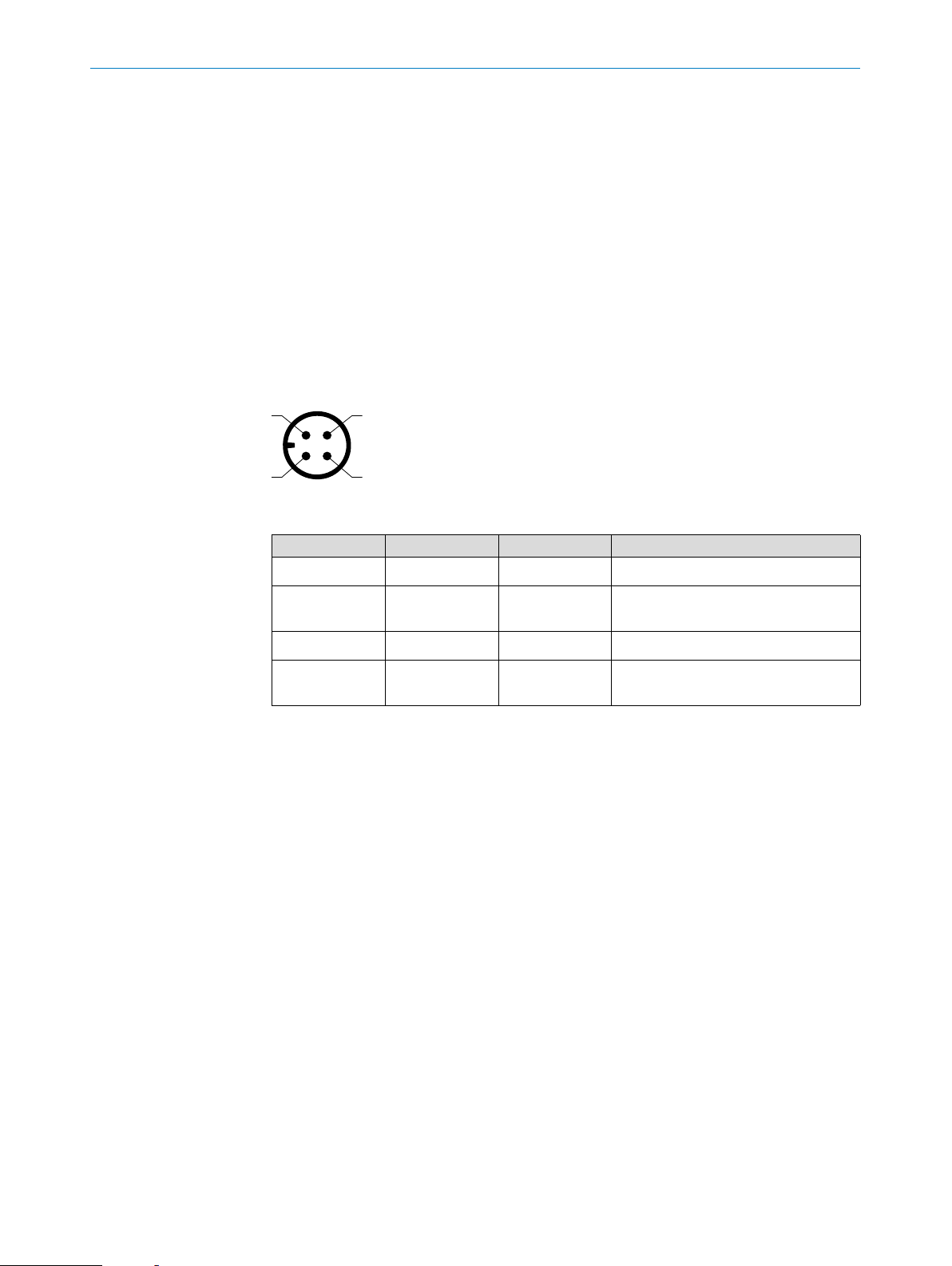
6.2.2 Pin assignment, M12 plug connector, 4-pin
Fig. 10: M12 x 1 plug connector, 4-pins
Contact Identication Wire color Description
1 L+ Brown Supply voltage
2 Q2 White Switching output/ push-pull/ digital
input
3 M Blue Ground
4 C/ Q1 Black Switching output/push-pull/IO-Link
communication
The table above shows only the standard pin assignment. Other pin assignments are
possible.
20
OPERATING INSTRUCTIONS | T-EASIC® 8023072/ 2018-09-03 | SICK AG
Subject to change without notice
Page 21
7 Commissioning
7.1 Quick commissioning (with factory settings)
Quick commissioning is used in applications under reference conditions see “5.1 Instal-
lation conditions”.
Commissioning
7COMMISSIONING
1. Install the sensor in line with the installation conditions in “5 Mounting”. During
the T-Easic
®
installation process, the pipe system must be empty and not pressur-
ized.
2. Switch on the supply voltage.
The sensor performs a self-test and is then ready for operation (with default settings: see “13 Factory settings”).
The display (Industrial version only) shows the current measured value.
In the event of problems during commissioning, see “8 Troubleshooting”.
7.2 Operation
The T-Easic® Industrial version is operated using the display and the operating buttons.
For a detailed description of the operating buttons and their functions, see “7.2.1 Dis-
play, LEDs and operating buttons (Industrial version only)”.
®
The T-Easic
face (see “7.2.4 IO-Link”).
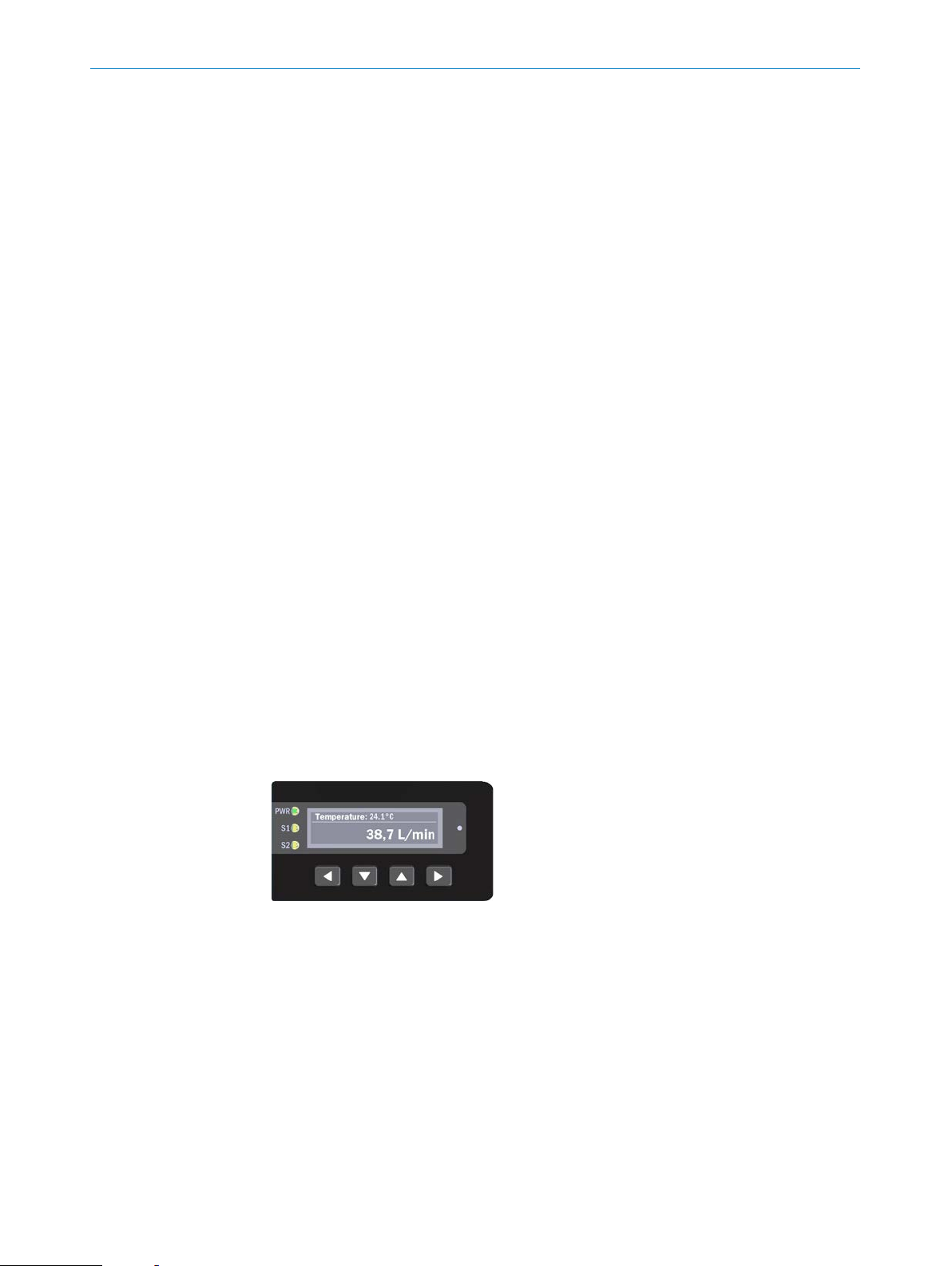
7.2.1 Display, LEDs and operating buttons (Industrial version only)
Setting, values, information and error messages are shown on the OLED display. The
OLED display switches o after 5 minutes of non-use.
The display is aligned horizontally to the axis of the measurement probe. The display
(the gures shown) can be rotated by 180°(see “7.4.12 Display Mode (Industrial ver-
sion only)”).
(both versions) can be congured via the IO-Link 1.1 communication inter-
Fig. 11: Display (Industrial version only)
To navigate through the menu structure use the arrow buttons and display.
Right and left arrow buttons allow to navigate in the menu and immediately conrm the
entry when selecting (nothing has to be conrmed/saved explicitly).
Up and down arrow buttons select options and accept the option directly.
Arrow down button: For changing values and accessing submenu
7.2.2 Information shown on the display (Industrial version only)
The display shows current values regarding ow and temperature. If an additional information or warning occurs the display alternates between current values and message
every 3.5 seconds.
Subject to change without notice
OPERATING INSTRUCTIONS | T-EASIC® 8023072/2018-09-03| SICK AG
21
Page 22
7 COMMISSIONING
If more than one information (or warning/ failure) is present (up to three are possible)
the display alternaters sequentially every 2 seconds between the messages and the
current values. For more details about messages shown on the display see “8.1 Error
message on the display (Industrial version only)”.
Temperature: 10.5°C<>
Flow 44,5 %
Temperature: 10.5°C<>
1,04 m/s
Temperature: 10.5°C<>
10000 L/min
Flow: 44.5%<>
10.5 °C
Fig. 12: Homepage and error messages
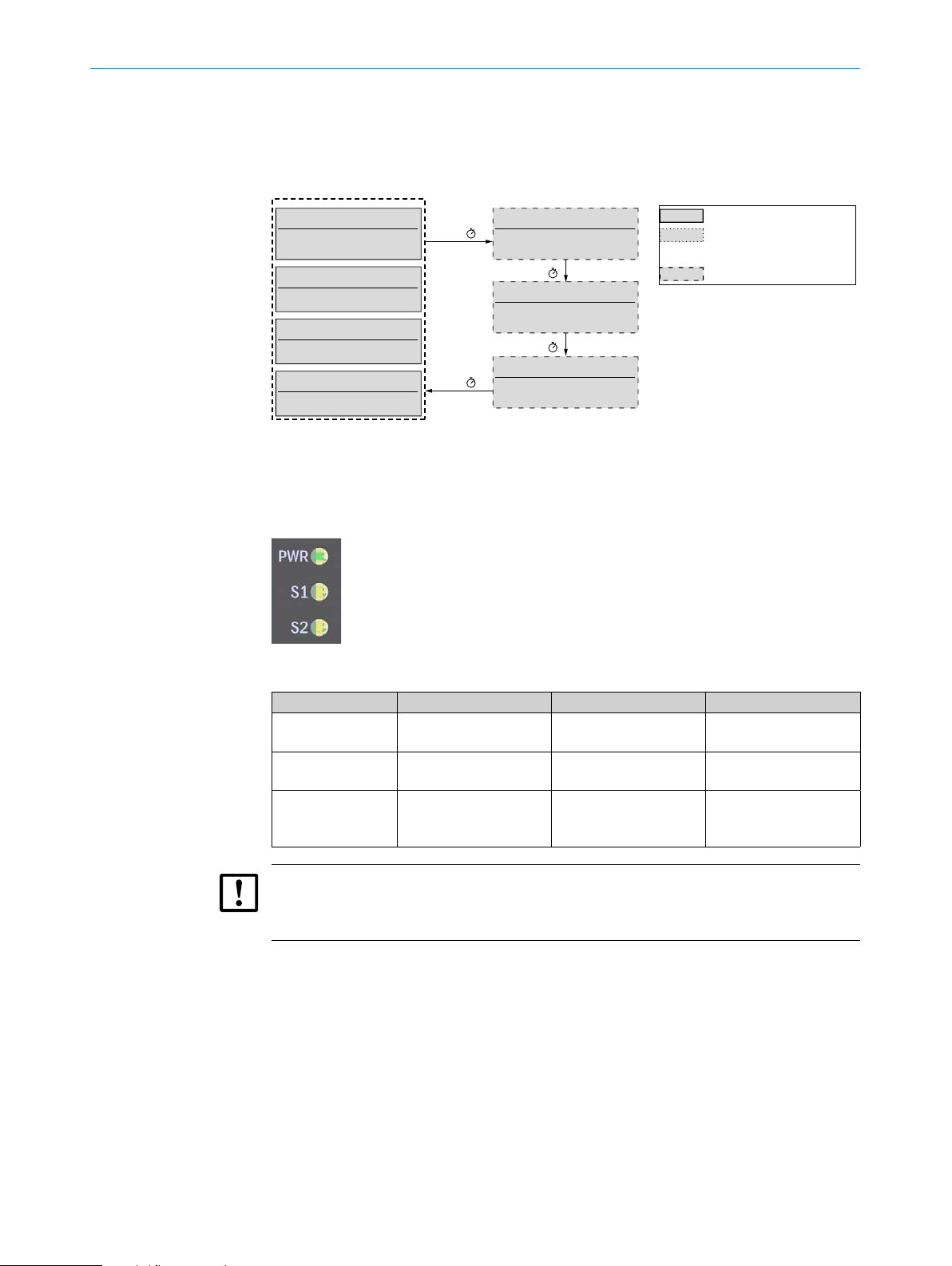
7.2.3 LEDs (Industrial version only)
On the left side of the display there are three LEDs to indicate:
Fig. 13: LEDs on the Indusrial version
3,5 s
2 s
Information
Shortcut Output Q1
2 s
Warning
Process Temperature
2 s
Failure
ErrorCode #6428
Always available
Conguration-
dependent
Failure
LED Status on Status o Status ashing
PWR
S1
S2
IMPORTANT
If the device is in error state, S1 and S2 ash simultaneously (check the displayed
message).
7.2.4 IO-Link
For operation via IO-Link, an IODD le, function blocks of common PLCs and a description of the available telegram parameters can be downloaded from www.sick.com.
7.3 Measurement conguration
The sensor can be congured using dierent measuring parameters.
Firstly it has to be determinded whether the sensor should be operated in Velocity
mode (relative or absolute) or Volume absolute mode or whether it should be taught.
operating voltage is
applied
switching output Q1
active
switching output Q2
active
operating voltage is not
present
switching output Q1
inactive
switching output Q2
inactive
Flashes for IO-Link
communication
-
device is in warning
state (see displayed
message)
22
OPERATING INSTRUCTIONS | T-EASIC® 8023072/ 2018-09-03 | SICK AG
Subject to change without notice
Page 23

Secondly it is possible to choose the medium between three dierent options.
There are several possibilities to congure the Measurement Mode:
− Velocity relative (%): the velocity is shown in percentage of the full scale.
− Velocity absolute: the velocity is shown as absolute measurement with the unit
chosen for the Unit Velocity parameter (see “7.4.3 Unit Volume”).
− Volume absolute: the volume is shown as absolute measurement with the unit
chosen for the Unit Volume (see “7.4.3 Unit Volume”).
− Teach relative (%): when the measured medium diers from the preset available
media (water, Oil A or Oil B) a teach procedure can be done to optimize the performanc of the sensor. Then the ow velocity is shown as percentage of the ow
range between the taught maximum and minimum ow.
If a Velocity mode or the Volume mode is selected it is possible to choose the type of
Medium (Water, Oil A or Oil B). The closer the actual medium is to the chosen type the
better the performance of the sensor.
Oil A and Oil B have the following specications:
− Oil A: viscosity 5 cSt at 26 °C
− Oil B: viscosity 49 cSt at 26 °C
7COMMISSIONING
If the sensor shows static 0% or 100%, even if the correct media is chosen, the media
does not t. Please teach in the media, see “7.3.2 Conguration of the Measurement
Mode based on Teach relative as example”.
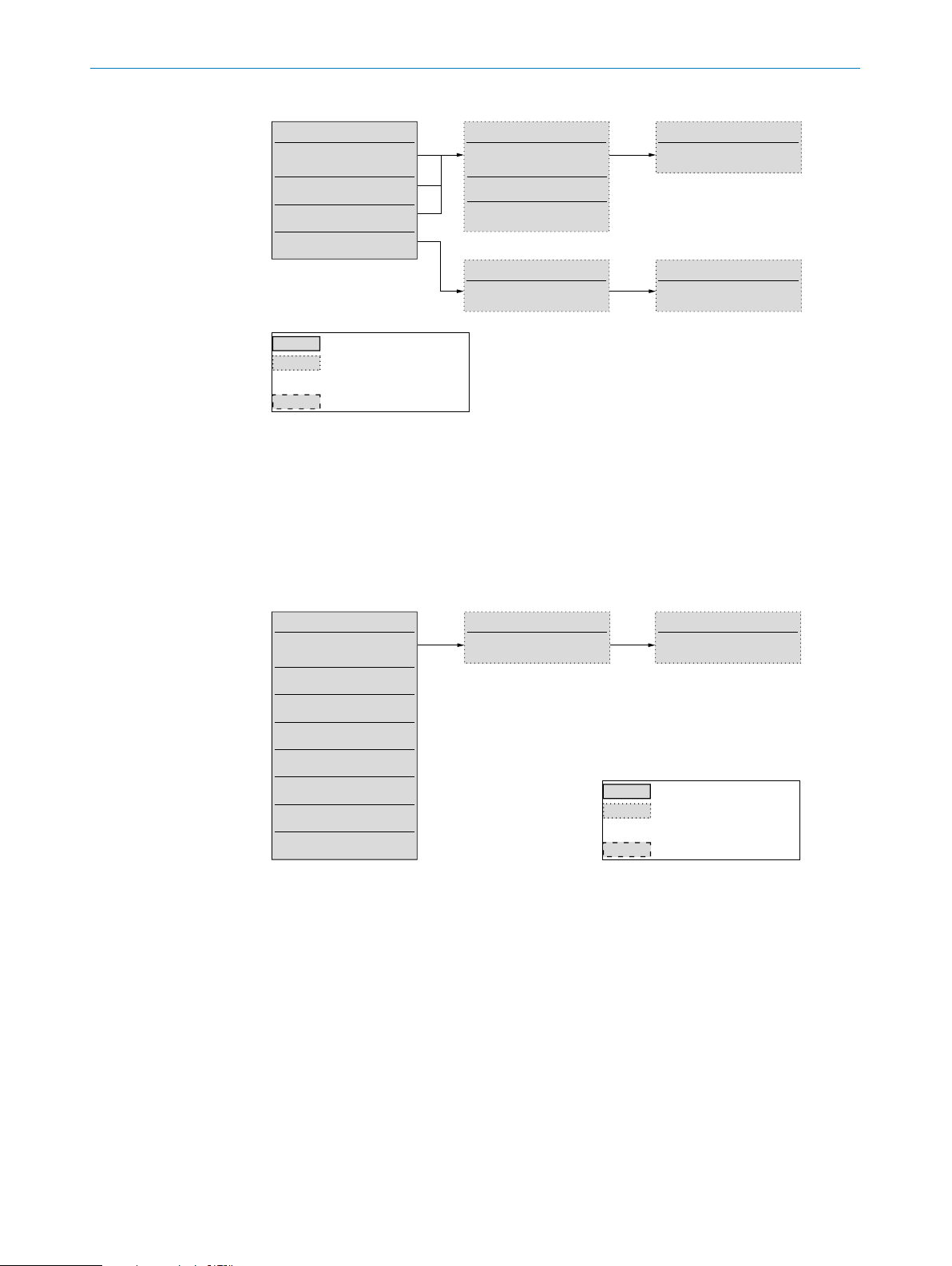
7.3.1 Conguration of the Measurement Mode based on Volume absolute as example
1. Select the Measurement Mode menu using the arrow pushbuttons (left/right).
2. Select the Volume absolute parameter using the arrow pushbuttons (up/down).
3. Select the Medium parameter using the right arrow pushbutton.
4. Select Water, Oil A or Oil B using the arrow pushbuttons (up/down).
5. Select the Pipe Diameter using the right arrow pushbutton (the unit for the diam-
eter can be selected in the advanced menu settings, see “7.4.1 Unit Pipe Diame-
ter”).
6. Increase or decrease the value using the arrow pushbuttons (up/down).
7.3.2 Conguration of the Measurement Mode based on Teach relative as example
1. Select the Measurement Mode menu using the arrow pushbuttons (left/right).
2. Select the Teach relative (%) parameter using the arrow pushbuttons (up/down).
3. Access the Teac h menu using the right arrow pushbutton.
4. Start the system and ensure maximal ow rate in the pipe.
5. Select the Teach max? parameter using the up/down arrow pushbutton.
While the teach cycle is running the message run ... is displayed.
The message Teach OK is displayed after a successful teach. Should the teach fail,
the message Teach not OK is displayed and the steps above must be repeated.
Subject to change without notice
6. Reduce the ow rate to minimum ow rate.
7. Select the Teach min? parameter using the arrow pushbuttons (up/down) (parameter is only visible after a successful Teach max? procedure).
While the teach cycle is running the message run ... is displayed.
The message Teach OK is displayed after a successful teach. Should the teach fail,
the message Teach not OK is displayed and the steps above must be repeated.
OPERATING INSTRUCTIONS | T-EASIC® 8023072/2018-09-03| SICK AG
23
Page 24
7 COMMISSIONING
<>
<>
<>
<>
<>
Measurement Mode
Velocity
Velocity
Volume
Teach
Always available
Conguration-
dependent
Failure
Fig. 14: Conguration Measurement Mode menu structure
7.3.3 Conguration of Q1 and Q2
Q1 and Q2 can be congured as hysteresis output for ow (normally open or normally
closed), window output for ow (normally open or normally closed), hysteresis output
for temperature (normally open or normally closed) and window output for temperature
(normally open or normally closed). Q2 can be disabled (O Pin Q2 inactive selected).
Q2 can be congured as Input in Boolean logic with Q1 (AND or OR).
relative (%)
absolute
absolute
relative (%)
Medium<>
Water
Pipe Diameter
25 mm
Oil A
Oil B
Teach<>
Teach max?
Teach
Teach min?
Q1 Mode
Hysteresis norm open
Flow
Flow
Hysteresis norm closed
Flow
Flow
Temp
Temp
Temp
Temp
Window norm open
Window norm closed
Hysteresis norm open
Hysteresis norm closed
Window norm open
Window norm closed
Fig. 15: Q1 Mode menu structure
Q1 Switchpoint 1<>
20.0 [unit]
Q1 Switchpoint 2
40.0 [unit]
Always available
Conguration-
dependent
Failure
24
OPERATING INSTRUCTIONS | T-EASIC® 8023072/ 2018-09-03 | SICK AG
Subject to change without notice
Page 25
7COMMISSIONING
<>
<>
Q2 Mode
Flow
Hysteresis norm open
Flow
Hysteresis norm closed
Flow
Flow
Temp
Hysteresis norm open
Temp
Hysteresis norm closed
Temp
Temp
Input
Input
Off
Window norm open
Window norm closed
Window norm open
Window norm closed
AND with Q1
OR with Q1
Pin Q2 inactive
Q2 Switchpoint 1<>
20.0 [unit]
Fig. 16: Q2 Mode menu structure
7.3.4 Conguration of the switching output Q1 and Q2
If the ow (or temperature) is uctuating around the set value, the hysteresis keeps the
switching status of the outputs stable.
When the ow (or temperature) is increasing, the output switches when the respective
switching point (SP1) is reached; if the ow (or temperature) sinks again, the output
switches back only after the reset switching point (SP2) has been reached.
Q2 Switchpoint 2
40.0 [unit]
Always available
Conguration-
dependent
Failure
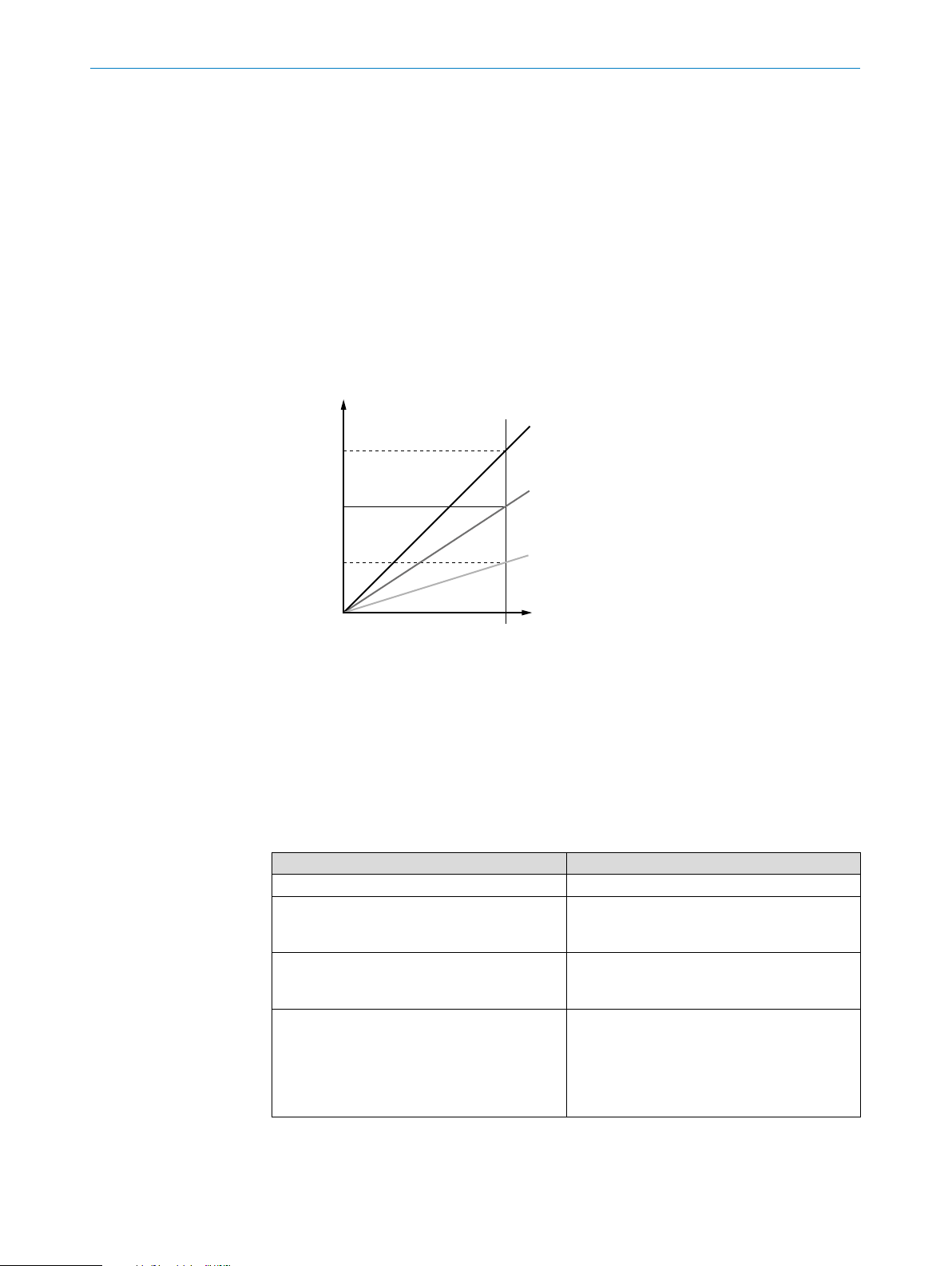
7.3.5 Normally open with congurable hysteresis
Conguration (based on Q1 for ow as an example)
The window function enables monitoring of a dened range. If the ow (or temperature)
is between window high (SP1) and window low (SP2), the output will be active (normally
open) and/or inactive (normally closed).
The error status of the measuring device reects the cable break monitoring. During
an error status, the measuring device switches to the safe state; the safe state of the
electronic is in pull-down conguration.
As far as the downstream signal evaluation is concerned, this corresponds to a cable
break.
1. Select Q1 Mode using the arrow pushbuttons (left/right).
2. Select Flow Hysteresis norm open using the arrow pushbuttons (up/down).
3. Select Q1 Switchpoint 1 (SP1) using the right arrow pushbutton.
4. Increase or decrease the value using the arrow pushbuttons (up/down).
5. Select Q1 Switchpoint 2 (SP2) using the right arrow pushbutton.
6. Increase or decrease the value using the arrow pushbuttons (up/down).
7. Congure the delay mode and time (see “7.4.7 Delay Mode Q1”).
Switching output behavior
Subject to change without notice
Flow / temperature
OPERATING INSTRUCTIONS | T-EASIC® 8023072/2018-09-03| SICK AG
25
Page 26

7 COMMISSIONING
inactive
inactive
SP1
SP2
active
Fig. 17: Normally open with congurable hysteresis
7.3.6 Normally closed with congurable hysteresis
t
Conguration (based on Q1 for ow as an example)
1. Select Q1 Mode using the arrow pushbuttons (left/right).
2. Select Flow Hysteresis norm closed using the arrow pushbuttons (up/down).
3. Select Q1 Switchpoint 1 (SP1) using the right arrow pushbutton.
4. Increase or decrease the value using the arrow pushbuttons (up/down).
5. Select Q1 Switchpoint 2 (SP2) using the right arrow pushbutton.
6. Increase or decrease the value using the arrow pushbuttons (up/down).
7. Congure the delay mode and time (see “7.4.7 Delay Mode Q1”).
Switching output behavior
Flow / temperature
SP1
SP2
t
26
active
Fig. 18: Normally closed with congurable hysteresis
OPERATING INSTRUCTIONS | T-EASIC® 8023072/ 2018-09-03 | SICK AG
Subject to change without notice
Page 27

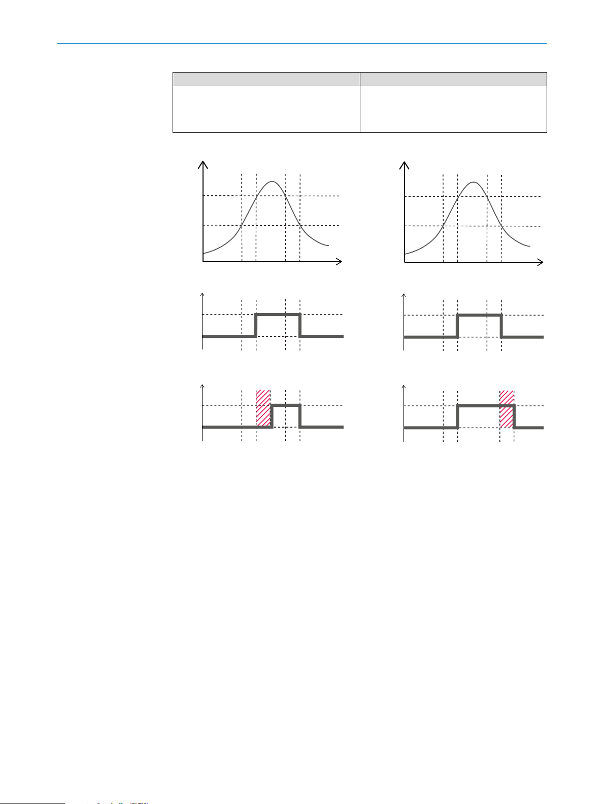
7.3.7 Normally open with window function
Conguration (based on Q1 for ow as an example)
1. Select Q1 Mode using the arrow pushbuttons (left/right).
2. Select Flow window norm open using the arrow pushbuttons (up/down).
3. Select Q1 Switchpoint 1 (SP1) using the right arrow pushbutton.
4. Increase or decrease the value using the arrow pushbuttons (up/down).
5. Select Q1 Switchpoint 2 (SP2) using the right arrow pushbutton.
6. Increase or decrease the value using the arrow pushbuttons (up/down).
7. Congure the delay mode and time (see “7.4.7 Delay Mode Q1”).
7COMMISSIONING
Subject to change without notice
OPERATING INSTRUCTIONS | T-EASIC® 8023072/2018-09-03| SICK AG
27
Page 28

7 COMMISSIONING
t
inactive
inactive
Switching output behavior
Flow / temperature
SP1
SP2
active
Fig. 19: Normally open with window function
7.3.8 Normally closed with window function
Conguration (based on Q1 for ow as an example)
1. Select Q1 Mode using the arrow pushbuttons (left/right).
2. Select Flow window norm closed using the arrow pushbuttons (up/down).
3. Select Q1 Switchpoint 1 (SP1) using the right arrow pushbutton.
4. Increase or decrease the value using the arrow pushbuttons (up/down).
5. Select Q1 Switchpoint 2 (SP2) using the right arrow pushbutton.
6. Increase or decrease the value using the arrow pushbuttons (up/down).
7. Congure the delay mode and time (see “7.4.7 Delay Mode Q1”).
Switching output behavior
Flow / temperature
SP1
SP2
28
t
active
Fig. 20: Normally closed with window function
OPERATING INSTRUCTIONS | T-EASIC® 8023072/ 2018-09-03 | SICK AG
Subject to change without notice
Page 29

7.3.9 Conguration of the digital input Q2
34
Input Q2
inactive
inactive
inactive
inactive
There are two selectable logics for Q2 input in the Q2 Mode menu:
− Input AND with Q1
− Input OR with Q1
7COMMISSIONING
This feature can be used (e.g.) to create a control logic with the signals coming from
two T-Easic
used as Q2 digital input on T-Easic
®
and using only one PLC digital input. In this case Q1 output of T-Easic® B is
®
A and the Q1 output of T-Easic® A is connected to
the PLC.
1
Q1Q2
2
Q1
Q1
Q1
OR
Q2 Q2
Q1 AND Q2 Q1 OR Q2
1PLC
2PLC Digital input
3T-Easic
4T-Easic
Fig. 21: Example of application using the digital input for Boolean logic with digital output
®
A
®
B
active
t
Internal Q1
active
t
External Q1 =
Internal Q1 AND Q2
active
t
External Q1 =
Internal Q1 OR Q2
active
t
Fig. 22: Digital input Q2 and Boolean logic explanation
Subject to change without notice
OPERATING INSTRUCTIONS | T-EASIC® 8023072/2018-09-03| SICK AG
29
Page 30

7 COMMISSIONING
7.4 Advanced menu (advanced settings)
From the Advanced Menu you can access the advance settings.
1. Select Advanced Menu using the arrow pushbuttons (left/right).
2. Select Open menu using the arrow pushbuttons (up/down).
3. Select the desired parameter using the arrow pushbuttons (left/right).
The following parameters are now accessible:
− Unit Pipe Diameter
− Unit Velocity
− Unit Volume
− Unit Temperature
− Filter (process data)
− Linear Flow Factor
− Delay Mode Q1
− Delay Time Q1
− Delay Mode Q2
− Delay Time Q2
− Simulation
− Display Mode
− Factory Reset
− Display Lock
− Password
− Close Cong
30
OPERATING INSTRUCTIONS | T-EASIC® 8023072/ 2018-09-03 | SICK AG
Subject to change without notice
Page 31

From
<>
<>
<>
<>
Open Menu
7COMMISSIONING
Unit Pipe Diameter<>
mm
inch
Filter (process data)<>
Off
Unit Velocity<>
m/s
ft/s
Linear Flow Factor<>
100 %
100 ms
200 ms
300 ms
500 ms
1 sec
2 sec
3 sec
5 sec
10 sec
Meter per second
Foot per second
Unit Volume<>
L/min
L/h
3
m
/h
gpm
gph
3
ft
/min
Delay Mode Q1<>
Liter per minute
Liter per hour
Cubic meter per hour
US Gallon per minute
US Gallon per hour
Cubic foot per minute
Off
Ton
Toff
Ton&Toff
Pulse
Delay
Delay
Delay
One Shot
Unit Temperature
°C
°F
Delay Time Q1
100 ms
Celsius
Fahrenheit
Delay Mode Q2<>
Off
Ton
Toff
Ton&Toff
Pulse
Delay
Delay
Delay
One Shot
Delay Time Q2<>
0 ms
Always available
Conguration-
dependent
Failure
Factory Reset<>
Reset all?
Display Lock<>
inactive
active
HMI unlocked
HMI locked
!Password!
Simulation<>
Off
0 %
25 %
50 %
75 %
100 %
-25°C
0°C
...°C
+150°C
Failure
Simulation inactive
Flow Simulation
Flow Simulation
Flow Simulation
Flow Simulation
Flow Simulation
Temp Simulation
Temp Simulation
Temp Simulation
Temp Simulation
simulate Failure
Password<>
login?
Display Mode
Flow & Temperature standard
Flow & Temperature 180° turned
Temperature & Flow standard
Temperature & Flow 180° turned
Advanced Menu
Close Menu
Unit Pipe Diameter
To
Subject to change without notice
OPERATING INSTRUCTIONS | T-EASIC® 8023072/2018-09-03| SICK AG
31
Page 32

7 COMMISSIONING
7.4.1 Unit Pipe Diameter
In this submenu you can congure the inner pipe diameter. This value is necessary to
calculate the correct ow volume.
You can congure the unit of the diameter. The following units are available:
− mm
− inch
7.4.2 Unit Velocity
In this submenu you can dene the measuring unit of the velocity. The following units
are available:
− m/s
− ft/s
7.4.3 Unit Volume
In this submenu you can dene the measuring unit of the volume. The following units
are available:
− L/min
− L/h
− m
− gpm
− gph
− ft
7.4.4 Unit Temperature
In this submenu you can dene the measuring unit of the temperature. The following
units are available:
− °C
− °F
7.4.5 Filter (process data)
Smoothing of the measured value, e.g., if ow is irregular (e.g. when pumps are starting
and stopping). For fast changes, the average of the measured values over a predened
number of seconds is output.
The following values are available:
− 100 ms
− 200 ms
− 300 ms
3
/h
3
/min
32
− 500 ms
− 1 s
− 2 s
− 3 s
− 5 s
− 10 s
− O
OPERATING INSTRUCTIONS | T-EASIC® 8023072/ 2018-09-03 | SICK AG
Subject to change without notice
Page 33
If the value O is selected, the lter function is disabled.
Linear Flow
Full Scale F. S.
150 %
100 %
50 %
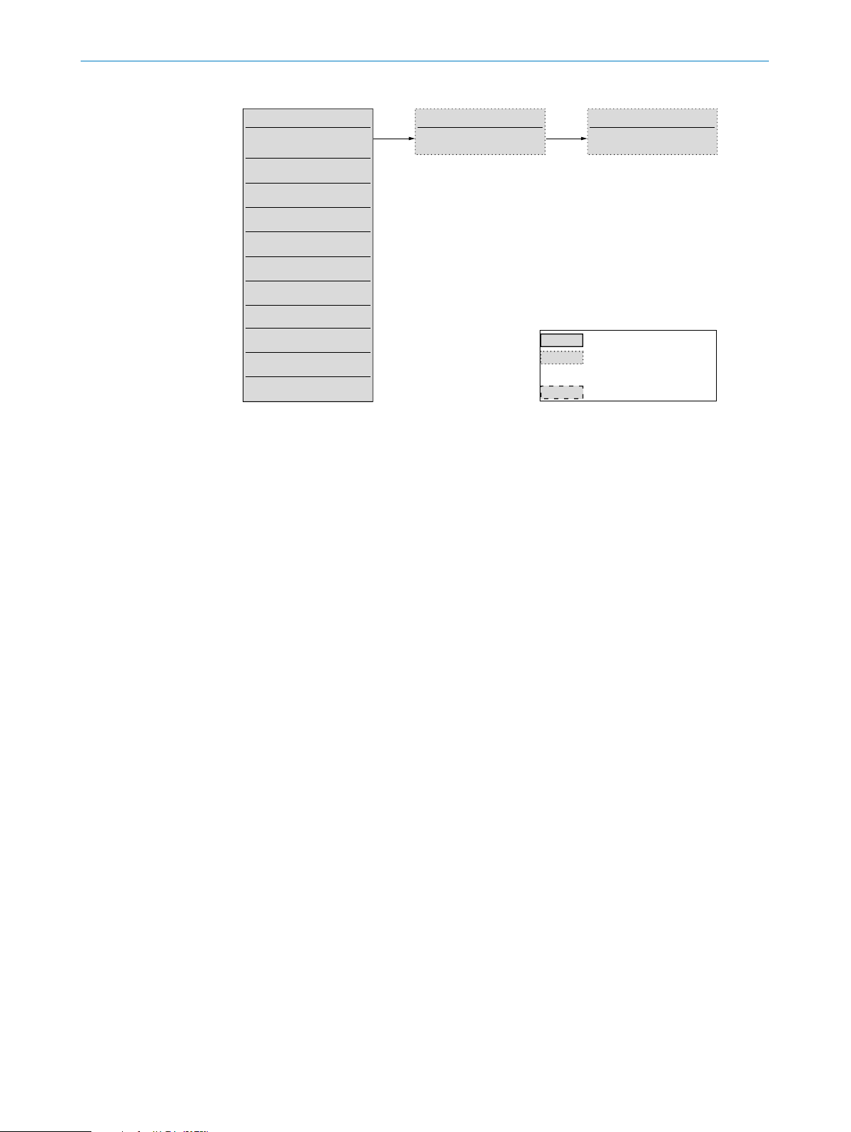
7.4.6 Linear Flow Factor
With Linear Flow Factor the sensor can be adjusted to a reference ow in the applica-
tion.
This menu is available only if Velocity relative (%) or Velocity absolute or Volume abso-
lute is selected in Measurement Mode menu.
The specic adjustment allows changing the slope of the curve of measured values. The
slope is given in percentage. The values of this factor can be chosen between 50 % and
150 %. The factory setting is 100%.
The Linear Flow Factor inuences the process data. It is not visible after a ow teach-in
procedure.
Factor
7COMMISSIONING
1
F. S.
2
F. S.
Fig. 23: Linear Flow Factor examples
1 Curve with adjustment 1
2 Factory setting curve
3 Curve with adjustment 2
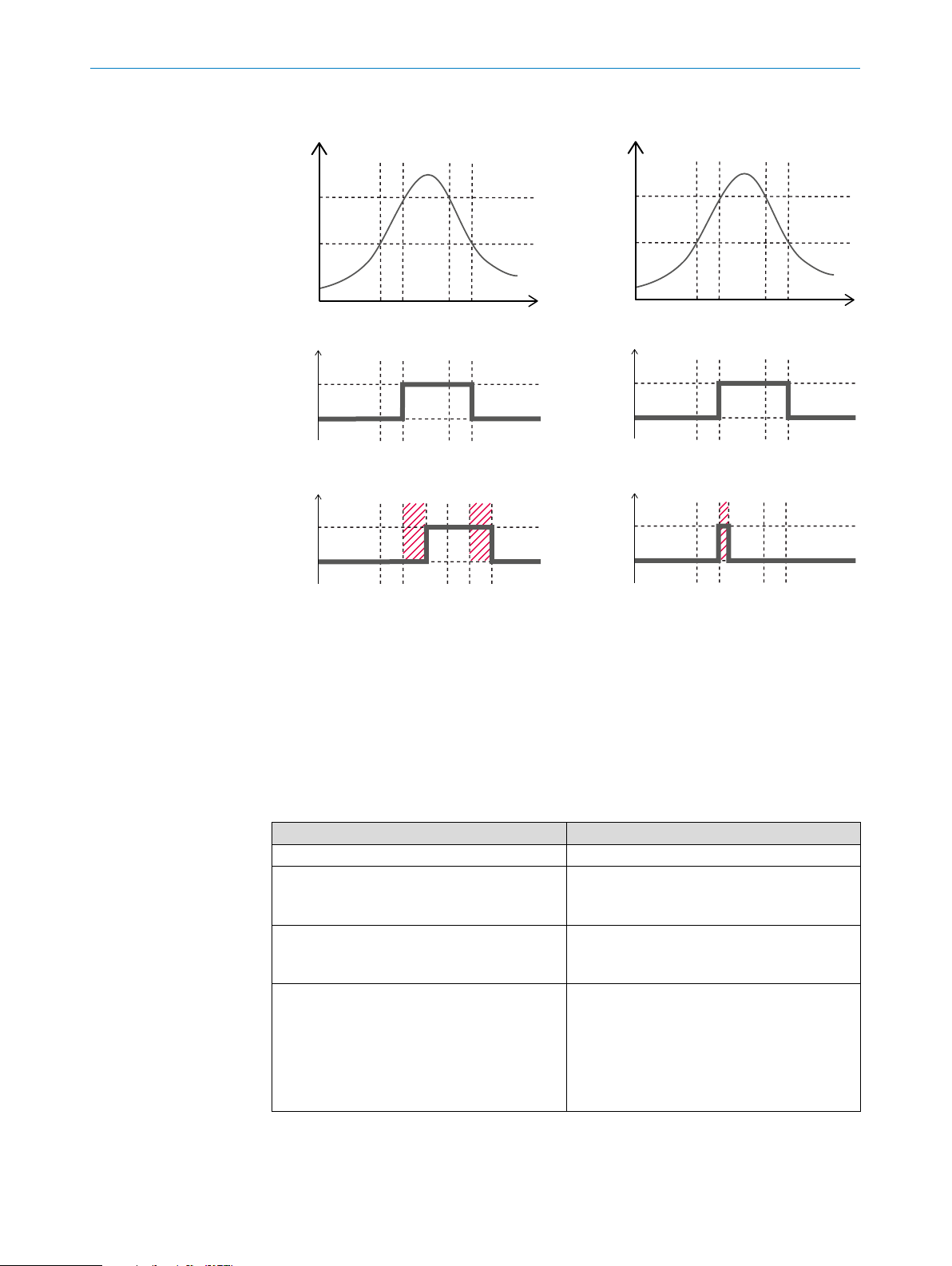
7.4.7 Delay Mode Q1
This parameter denes the delay mode applied to Q1. The following parameters are
available:
F. S.
3
Flow
Parameter Function
O No delay applied on Q1 status change.
Ton Delay When the Q1 Switchpoint 1 is reached, the
status of Q1 will not switch till the Delay time
Q1 (see “7.4.8 Delay Time Q1”) is expired.
To Delay When the Q1 Switchpoint 2 is reached, the
status of Q1 will not switch till the Delay time
Q1 (see “7.4.8 Delay Time Q1”) is expired.
Ton&To Delay When the Q1 Switchpoint 1 is reached, the
status of Q1 will not switch till the Delay time
Q1 (see “7.4.8 Delay Time Q1”) is expired.
When the Q1 Switchpoint 2 is reached, the
status of Q1 will not switch till the Delay time
Q1 (see “7.4.8 Delay Time Q1”) is expired.
Subject to change without notice
OPERATING INSTRUCTIONS | T-EASIC® 8023072/2018-09-03| SICK AG
33
Page 34
7 COMMISSIONING
inactive
inactive
Flow / Temperature
t
t
t
inactive
inactive
Flow / Temperature
Parameter Function
Pulse One Shot When the Q1 Switchpoint 1 is reached, the
status of Q1 will switch and when the Delay
time Q1 is expired (see “7.4.8 Delay Time Q1”)
Q1 will switch back to the previous status.
SP1
SP2
Q1 without any delay
active
Q1 Ton
active
t
t
Delay
t
SP1
SP2
Q1 without any delay
active
Q1 Toff
active
Delay
Fig. 24: Delay Mode Q1 set as Ton Delay / Hysteresis - Normally open (left) and Delay Mode Q1
set as To Delay / Hysteresis - Normally open (right)
34
OPERATING INSTRUCTIONS | T-EASIC® 8023072/ 2018-09-03 | SICK AG
Subject to change without notice
Page 35
7COMMISSIONING
inactive
inactive
Flow / Temperature
t
t
t
inactive
inactive
Flow / Temperature
SP1
SP2
Q1 without any delay
active
Q1 Ton
active
Delay
t
t
Toff
Delay
t
SP1
SP2
Q1 without any delay
active
Q1 Pulse
active
One Shot
Fig. 25: Delay Mode Q1 set to Ton&To Delay / Hysteresis - Normally open (left) and Delay Mode
Q1 set to Pulse One Shot / Hysteresis - Normally open (right)
7.4.8 Delay Time Q1
7.4.9 Delay Mode Q2
In this submenu you can dene the time applied to the delay of Q1 accordingly to the
mode dened under Delay Mode Q1 (see “7.4.7 Delay Mode Q1”).
This parameter denes the delay mode applied to Q2. The following parameters are
available:
Parameter Function
O No delay applied on Q2 status change.
Ton Delay When the Q2 Switchpoint 1 is reached, the
status of Q2 will not switch till the Delay Time
Q2 is expired (see “7.4.10 Delay Time Q2”).
To Delay When the Q2 Switchpoint 2 is reached, the
Ton&To Delay When the Q2 Switchpoint 1 is reached, the
status of Q2 will not switch till the Delay Time
Q2 is expired (see “7.4.10 Delay Time Q2”).
status of Q2 will not switch till the Delay Time
Q2 is expired (see “7.4.10 Delay Time Q2”)
and when the Q2 Switchpoint 2 is reached,
the status of Q2 will not switch till the Delay
Time Q2 is expired (see “7.4.10 Delay Time
Q2”).
Subject to change without notice
OPERATING INSTRUCTIONS | T-EASIC® 8023072/2018-09-03| SICK AG
35
Page 36

7 COMMISSIONING
7.4.10 Delay Time Q2
7.4.11 Simulation
Parameter Function
Pulse One Shot When the Q2 Switchpoint 1 is reached, the
status of Q2 switch and when the Delay Time
Q2 is expired (see “7.4.10 Delay Time Q2”) Q2
will switch back to the previous status.
In this submenu you can dene the time applied to the delay of Q2 accordingly to the
mode dened under Delay Mode Q2 (see “7.4.9 Delay Mode Q2”).
Even if there is no liquid in the measurement channel yet, it is possible to select a ow
or temperature in the menu in order to test the sensor conguration. You can also simu-
late a failure status (safe-state simulation).
b Set the desired value for ow or temperature using the arrow pushbuttons (up/
down).
The following parameters are available:
− O
− Sim Flow 25 %
− Sim Flow 50 %
− Sim Flow 75 %
− Sim Flow 100 %
− Sim Temp -25 °C
− Sim Temp 0 °C
− Sim Temp +25 °C
− Sim Temp +50 °C
− Sim Temp +75 °C
− Sim Temp +100 °C
− Sim Temp +125 °C
− Sim Temp +150 °C
− Failure
When a simulated condition is activated the display shows cyclically the message Info
Simulation is active. If a simulated failure condition is activated the display shows cyclically the message Failure Failure Simulation is active.
7.4.12 Display Mode (Industrial version only)
In this submenu you can dene the information shown on the display when operating.
The following parameters are available:
36
Parameter Function
Flow & Temp Standard The ow is shown in the lower part of the
display and the temperature is shown in the
upper part.
OPERATING INSTRUCTIONS | T-EASIC® 8023072/ 2018-09-03 | SICK AG
Subject to change without notice
Page 37
7.4.13 Factory Reset
<>
7COMMISSIONING
Parameter Function
Flow & Temperature 180° turned The ow is shown in the lower part of the
display and the temperature is shown in the
upper part but the display is fully rotated of
180° compared to the previous setting.
Temp & Flow Standard The temperature is shown in the lower part of
the display and the ow is shown in the upper
part.
Temp & Flow 180° turned The temperature is shown in the lower part of
the display and the ow is shown in the upper
part but the display is fully rotated of 180°
compared to the previous setting.
In this submenu you can reset all parameters to factory settings. The following value is
available:
− Reset All?
b Reset to factory settings using the arrow pushbuttons (up/down).
7.4.14 Display Lock (Industrial version only)
7.4.15 Password
7.4.16 Advanced Menu (Close Menu)
7.5 Information
To avoid setting changes, the display of the Industrial version can be locked. When the
display is locked an unlocking code must be entered before applying any changes.
The code to unlock the display and buttons is 000387.
This submenu is reserved for SICK service only.
This submenu closes the advanced conguration menu. The following value is avaible:
− Close Menu
b Go back to the main menu using the arrow pushbuttons (up/down).
After you left the advanced menu Advanced menu - Open Menu is displayed.
In this menu you can check information relevant to the sensor.
Information
18411481
V1.22.2R
***
ApplicationSpecificTag
***
24.12 V
33.2 °C
Serial No.
Firmware Version
Device Specific Tag
Supply Voltage
Sensor Temp
Always available
Conguration-
dependent
Failure
Subject to change without notice
Fig. 26: Information menu structure
The following parameters are available:
OPERATING INSTRUCTIONS | T-EASIC® 8023072/2018-09-03| SICK AG
37
Page 38

7 COMMISSIONING
Parameter Function
Serial No Serial number of the device
Firmware Firmware version installed in the sensor
ApplicationSpecicTag Specic application name belonging to the
sensor
Device Specic Tag Indication of the device tag given to the sensor
Supply Voltage Actual supply voltage of the device
Internal Temp Indication of the temperature of the printed
circuit card of the sensor
38
OPERATING INSTRUCTIONS | T-EASIC® 8023072/ 2018-09-03 | SICK AG
Subject to change without notice
Page 39

8 Troubleshooting
8.1 Error message on the display (Industrial version only)
On the display are shown up to three error messages with highest priority. The messages that can appear on the display are listed in the following table.
Message Level Cause Solution
Supply Voltage too low Warning The minimum supply voltage is too
low.
Supply Voltage too high Failure The maximum supply voltage is too
high.
Low Voltage IO-Link Info The supply voltage is < 16 V thus the
IO-Link communication is no longer
possible.
Simulation is active Info The simulation function is active.
State of the outputs does not corre-
spond to the actual measured ow or
temperature in the process.
Failure Simulation is active Info The “safe-state” simulation of the
sensor is active. State of the outputs
corresponds to the safe state of the
device.
MemoryInvalid Failure Device memory contains invalid
conguration. The sensor goes into
safe state.
Check the supply voltage and if necessary adjust according the specications (see “11 Technical data”).
Check the supply voltage and if necessary adjust according the specications (see “11 Technical data”).
Check the supply voltage and if necessary adjust according the specications (see “11 Technical data”).
Deactivate the Simulation function if
necessary.
Deactivate the Simulation function if
necessary.
Contact SICK.
8TROUBLESHOOTING
Outputdriver Error Failure Overload of the driver oft he switch-
ing output. The sensor goes into safe
state.
Q1 Shortcut Info Short circuit or overload on Q1. Reduce the load of the output to the
Q1: Switchpoint out of Range Warning Switch point of Q1 is outside the set
measuring range
Q1: Distance SP1 to SP2 too
small
Q2 Shortcut Info Short circuit or overload on Q2. Reduce the load of the output to the
Q2: Switchpoint out of Range Warning Switch point of Q2 is outside the set
Sensor shows a static value
of 0% or 100%
Q2: Distance SP1 to SP2 too
small
Ambient Temperature too
high
Warning Switchpoint1 of Q1 is too close to the
Switchpoint2 of Q1. The settings may
lead to unwanted sensor behaviour.
measuring range.
Media does not t to the teached or
chosen media of the sensor
Warning Switchpoint1 of Q2 is too close to the
Switchpoint2 of Q2. The settings may
lead to unwanted sensor behaviour.
Warning Ambient temperature is too high. Reduce the ambient temperature
Reduce the load of the output to the
maximum values according to the
specications (see “11 Technical
data”).
maximum values according to the
specications (see “11 Technical
data”).
Check settings and correct if necessary.
Check settings and correct if necessary.
maximum values according to the
specications (see “11 Technical
data”).
Check settings and correct if necessary.
Teach-in of the media (see “7.3
Measurement conguration 22”)
Check settings and correct if necessary.
according to the specications (see
“11 Technical data”).
Subject to change without notice
OPERATING INSTRUCTIONS | T-EASIC® 8023072/2018-09-03| SICK AG
39
Page 40
8 TROUBLESHOOTING
Message Level Cause Solution
Ambient Temperature too low Warning Ambient temperature is too low. Increase the ambient temperature
according to the specications (see
“11 Technical data”).
Medium Temperature too
high
Warning Process temperature of the medium
is too high.
Reduce the process temperature
according to the specications (see
“11 Technical data”).
Medium Temperature too low Warning Process temperature of the medium
is too low.
Increase the process temperature
according to the specications (see
“11 Technical data”).
Internal Error Failure Internal device error. The sensor
Contact SICK.
goes into safe state.
Sensor is not teached Warning The sensor is in teach mode but
there is no valid teach. The ow rate
Carry out correct Teach-Max and
Teach-Min.
is 0%. The outputs are set accordingly.
8.2 Outputs
Error Cause Solution
Switching output
does not behave as
expected
Conguration incorrect. Perform conguration of the switching output
(see “7.3 Measurement conguration”).
An error is pending; the sensor outputs are in the
Remove the cause of the error.
safe state.
Line break. Check cable.
40
OPERATING INSTRUCTIONS | T-EASIC® 8023072/ 2018-09-03 | SICK AG
Subject to change without notice
Page 41

9 Repair
Repair work on the sensor may only be performed by qualied and authorized personnel from SICK AG. Interference with or modications to the sensor on the part of the
customer will invalidate any warranty claims against SICK AG.
9.1 Maintenance
The T-Easic® is maintenance-free. We recommend performing the following actions
regularly:
Repair work on the sensor may only be performed by qualied and authorized personnel from SICK AG. Interference with or modications to the sensor on the part of the
customer will invalidate any warranty claims against SICK AG.
9.2 Returns
Rinse o and/or clean removed devices before returning them in order to protect our
employees and the environment from dangers posed by residue from measured mate-
rials. Faulty devices can only be examined when accompanied by a completed return
form. This form includes information about all materials which have come into contact
with the device, including those which were used for testing purposes, operation, or
cleaning. The return form is available from our website (www.sick.com).
9REPAIR
• Checking the measurement probe for deposits or build-up and abrasion.
• Checking the screw connections and plug-in connections.
Subject to change without notice
OPERATING INSTRUCTIONS | T-EASIC® 8023072/2018-09-03| SICK AG
41
Page 42

10 DISPOSAL
10 Disposal
Dispose of device components and packaging materials in compliance with applicable
country-specic waste treatment and disposal regulations for the region of use.
42
OPERATING INSTRUCTIONS | T-EASIC® 8023072/ 2018-09-03 | SICK AG
Subject to change without notice
Page 43

11 Technical data
11.1 Features
Measuring principle Calorimetric measurement method for determining
Media Aqueous and oil-based media
Range of selectable inner pipe diameter From 25 mm
Operating range Water 3 cm/s … 150 cm/s
Maximum process pressure 100 bar
Process temperature -40 °C ... +150 °C
IO-Link 1.1
Temperature measurement via IO-Link
1)
The probe tip must be in the center of the pipe to have the best accuracy performances
2)
For medium temperatures > 100 ° C, the distance from the bottom of the housing and the top
of the mounting adapter must be at least 25 mm. Probe length variant of 60 mm is not possible
if process temperature > 100 °C
11TECHNICAL DATA
the ow
1)
Oil 3 cm/s … 300 cm/s
16 bar (with clamp adapter p/n 2093548)
2)
COM3 (230,4 kbit/s)
11.2 Performance
1)
in the center of the pipe, probe alignment to the flow as per §5.2, fully filled pipe without air
bubbles, velocity from 10 cm/s to 100 cm/s, inlet zone > 30 cm, outlet zone < 30 cm, 26 °C ±
1 °C, 2 bar ± 1 bar
2)
Minimum ow velocity ≥ 3 cm/s (water and oil)
Maximum ow velocity ≤ 150 cm/s (water)
≤ 300 cm/s (oil)
Inlet zone 5 x DN
Outlet zone 3 x DN
Accuracy ow ± 10 % of F.S.
Reproducibility ow < 1 cm/s
1)
1)
Resolution ow (over IO-Link) velocity: 0.01 m/s; Volume: 0.1 L/min; Relative:
0.1 %
Temperature drift (ow) < 0.5 cm/(s*K)
1)
Response time (ow) < 2.5 s (lter o)
Accuracy temperature ± 1 °C
Resolution < 0.1 °C
Response time temperature (T90 time) < 6 s
2)
Operating mode Velocity relative (%)
Velocity absolute
Volume absolute
Teach relative (%)
Reference conditions: pipe inner diameter 25 mm, water, vertical installation in the pipe, tip
Under reference conditions as in 1) but only flow rate = 100 cm/s
Subject to change without notice
OPERATING INSTRUCTIONS | T-EASIC® 8023072/2018-09-03| SICK AG
43
Page 44

11 TECHNICAL DATA
11.3 Mechanics/materials
Process connection Without process connection (adapter needed for
Wetted parts Stainless steel 1.4404 / 316L
Housing material Industrial version: VISTAL
Gasket material (only clamp adapter
p/n 2093548)
Probe diameter 8 mm
Probe length 60 mm, 100 mm, 200 mm (tolerance ±1 mm)
Probe roughness
Enclosure rating (DIN EN 60529)
Minimum inner pipe diameter 25 mm in centric installation
Minimum insertion length 12 mm
Minimum distance probe tip to pipe wall 10 mm
Weight Industrial version: 77 gr
1)
welding seams excluded
2)
only with M12 plug tightened
installation)
®
/Polyester
Hygienic version: stainless steel 1.4404 /316L
FKM
1)
2)
Ra ≤ 0.8 μm
Industrial version: IP67
Hygienic version: IP67/IP69
Hygienic version: 195 gr
11.4 Ambient conditions
Ambient temperature, operation
Ambient temperature, storage -40 °C ... +80 °C
1)
According to UL listing: degree of contamination 3 (UL61010-1: 2012-05); air humidity: 80 %
at temperatures up to 31 °C; installation height: max. 3,000 m above sea level
1)
-40 °C ... +70 °C
44
OPERATING INSTRUCTIONS | T-EASIC® 8023072/ 2018-09-03 | SICK AG
Subject to change without notice
Page 45

11.5 Electrical connections
Supply voltage U
Power consumption < 2.0 W at 24 V DC (without any load on outputs)
Initialization time ≤ 5 s (IO-Link < 10 s)
Protection class III
Connection type Round connector M12 x 1, 4-pin
Output signal 2 Push-Pull digital outputs (Q2 selectable as digital
Output current ≤ 100 mA (per each output)
Signal voltage HIGH > U
Signal voltage LOW ≤ 2 V
Inductive load 1 H
Capacitive load 100 nF (2.5 nF, IO-Link mode)
Limits of digital input HIGH state voltage: it depends on Uv
EMC EN 61326-1, EN 61326-2-3
MTTF > 200 years
1)
All connections are reverse polarity and overcurrent protected. Q1 and Q2 are short-circuit
protected.
Use an energy-limited circuit for power supply as per UL61010-1 3rd Ed.
11TECHNICAL DATA
1)
V
9 V DC ... 30 V DC
input) for ow and temperature
- 2 V
V
LOW state voltage < 4.0 V
Subject to change without notice
OPERATING INSTRUCTIONS | T-EASIC® 8023072/2018-09-03| SICK AG
45
Page 46

12 DIMENSIONAL DRAWINGS
Ø 32
79
L
100 (3.94)
200 (7.87)
12 Dimensional drawings
All dimensions are provided in mm (inches).
12.1 Industrial version
(3.11)
10.2
40.3
(0.4)
(1.59)
Ø 8
(0.31)
(1.26)
M12x1
4.5
(0.18)
L: 60 (2.36)
Fig. 27: Dimensional drawing Industrial version
46
OPERATING INSTRUCTIONS | T-EASIC® 8023072/ 2018-09-03 | SICK AG
Subject to change without notice
Page 47

12.2 Hygenic version
Ø 32
79
L
(2.36)
(3.94)
(7.87)
(3.11)
10.3
12DIMENSIONAL DRAWINGS
(1.26)
M12x1
(0,41)
Ø 8
(0.31)
Fig. 28: Dimensional drawing Hygienic version
12.3 Mounting adapters for T-Easic® FTS
12.3.1 Adapter G1/2 (p/n 5338774)
A
16
(0.63)
46
(1.81)
22
(0.87)
9,5
(0.37)
2,5
14,5
(0,10)
(0.57)
L: 60
100
200
(
8,2
0.32)
17,6
(0.69)
35,4
(1.39)
A
G 1/2 A
8,5
(
0.33)
A-A
Subject to change without notice
26
(
1.02)
Fig. 29: Dimensional drawing adapter G1/2 (p/n 5338774)
OPERATING INSTRUCTIONS | T-EASIC® 8023072/2018-09-03| SICK AG
47
Page 48
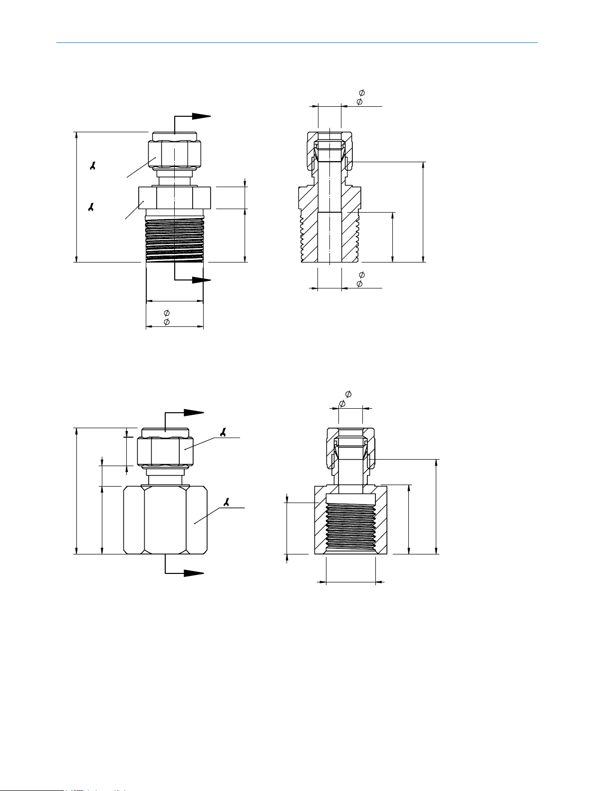
12 DIMENSIONAL DRAWINGS
12.3.2 Adapter 1/2" NPT (p/n 5338775)
A
16
(0.63)
8,2
(
0.32)
46
(1.81)
22
7,7
(0.30)
(0.87)
18,9
(0.74)
A
1/2" NPT
20,2
(
0.79)
Fig. 30: Dimensional drawing adapter 1/2" NPT (p/n 5338775)
12.3.3 Adapter M18 x 1.5 (p/n 2104208)
A
16
9,5
(0.37)
6,8
(0.27)
(1.65)
41,8
22,5
(0.89)
27
min. 17
(min. 0.67)
A-A
(
(
8
0,31)
8,5
0.33)
17,6
(0.69)
23
35,5
(1.39)
(0,91)
31,4
(1.23)
48
A
Fig. 31: Dimensional drawing adapter M18 x 1.5 (p/n 2104208)
OPERATING INSTRUCTIONS | T-EASIC® 8023072/ 2018-09-03 | SICK AG
M18x1,5
Subject to change without notice
Page 49
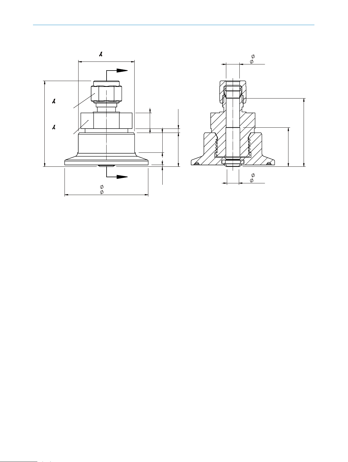
12.3.4 Adapter clamp DIN32676 DN25-40 (p/n 2093548)
12DIMENSIONAL DRAWINGS
51,9
(2.04)
16
(0.63)
22
(0.87)
34
(1.34)
8,2
(
0.32)
A
2,5
(0.47)
(0.04)
20,5
(0.10)
(0.81)
A-A
7,2
(
0.28)
9,5
(0.37)
12
A
50,5
(
1.99)
1
Fig. 32: Dimensional drawing adapter clamp DIN32676 DN25-40 (p/n 2093548)
23,6
(0.93)
41,4
(1.63)
Subject to change without notice
OPERATING INSTRUCTIONS | T-EASIC® 8023072/2018-09-03| SICK AG
49
Page 50

13 FACTORY SETTINGS
13 Factory settings
Factory settings can be restored via RstFac.
Parameter Value
Measurement Mode Relative (%)
Medium Water
Diameter 26 mm
Q1 Switchpoint 1 50 % (when Flow and Velocity relative are selected)
Q1 Switchpoint 2 30 % (when Flow and Velocity relative are selected)
Q1 Switchpoint 1 0.5 m/s (when Flow and Velocity absolute are selected)
Q1 Switchpoint 2 0.3 m/s (when Flow and Velocity absolute are selected)
Q1 Switchpoint 1 160 l/min (when Flow and Volume absolute are selected)
Q1 Switchpoint 2 95 l/min (when Flow and Volume absolute are selected)
Q1 Switchpoint 1 30 °C (when Temperature is selected)
Q1 Switchpoint 2 25 °C (when Temperature is selected)
Q1 Mode Flow Hysteresis norm open
Q2 Switchpoint 1 80 % (when Flow and Velocity relative are selected)
Q2 Switchpoint 2 60 % (when Flow and Velocity relative are selected)
Q2 Switchpoint 1 0.8 m/s (when Flow and Velocity absolute are selected)
Q2 Switchpoint 2 0.6 m/s (when Flow and Velocity absolute are selected)
Q2 Switchpoint 1 255 l/min (when Flow and Volume absolute are selected)
Q2 Switchpoint 2 190 l/min (when Flow and Volume absolute are selected)
Q2 Switchpoint 1 80 °C (when Temperature is selected)
Q2 Switchpoint 2 75 °C (when Temperature is selected)
Q2 Mode Flow Hysteresis norm closed
Unit Diameter mm
Unit Velocity m/s
Unit Temperature °C (Celsius)
Unit Volume L/min
Filter (process data) 1 s
Linear Flow Factor 100 %
Delay Mode Q1 O
Delay Mode Q2 O
Simulation O
Display Mode Flow & Temperature
Display Lock Inactive
ApplicationSpecicTag ***
Device Specic Tag ***
50
OPERATING INSTRUCTIONS | T-EASIC® 8023072/ 2018-09-03 | SICK AG
Subject to change without notice
Page 51

14 Accessories
Part number Type code Description
5338774 BEF-CFSG12-FTS1-COMPR. FITTING G1/2 Compression tting for T-Easic® FTS G1/2
5338775 BEF-CFSN12-FTS1-COMPR. FITTING 1/2"NPT Compression tting for T-Easic
2104208 BEF-CFSM18-FTS1-COMPR. FITTING M18X1,5 Compression tting for T-Easic
2093548 BEF-HA-TCLI10-FTS1-TRI-CLAMP Compression tting for T-Easic
DIN32676 DN25-40 (50.5 mm)
6052613 DOL-1204-G02MNI Cable IP69K - M12x1 4 pins - 2 meter straight
6052615 DOL-1204-G05MNI Cable IP69K - M12x1 4 pins - 5 meter straight
6052617 DOL-1204-G10MNI Cable IP69K - M12x1 4 pins - 10 meter straight
b More accessories can be found online at: www.sick.com
®
FTS 1/2" NPT
®
FTS M18 x 1.5
®
FTS clamp
14ACCESSORIES
Subject to change without notice
OPERATING INSTRUCTIONS | T-EASIC® 8023072/2018-09-03| SICK AG
51
Page 52
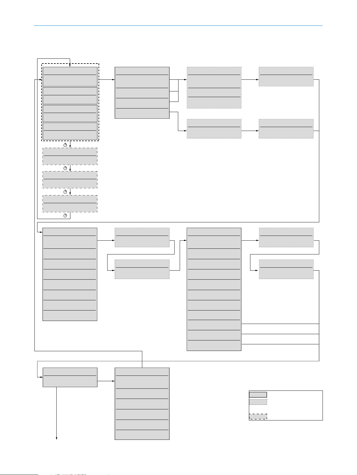
15 MENU OVERVIEW
<>
<>
<>
<>
15 Menu overview
Temperature: 10.5°C<>
Flow 44,5 %
Temperature: 10.5°C<>
1,04 m/s
Temperature: 10.5°C<>
Measurement Mode<>
Velocity
Velocity
Volume
Teach
10000 L/min
Flow: 44.5%<>
10.5 °C
3,5 s
Information
Shortcut Output Q1
2 s
Warning
Process Temperature
2 s
Failure
ErrorCode #6428
2 s
Q1 Mode<>
Flow
Hysteresis norm open
Flow
Hysteresis norm closed
Flow
Flow
Temp
Temp
Temp
Temp
Window norm open
Window norm closed
Hysteresis norm open
Hysteresis norm closed
Window norm open
Window norm closed
Q1 Switchpoint 1<>
20.0 [unit]
Q1 Switchpoint 2<>
40.0 [unit]
relative (%)
absolut
absolut
relative (%)
Medium<>
Water
Oil A
Unit Pipe Diameter
25 mm
Oil B
Teach<>
Teach max?
Q2 Mode<>
Flow
Hysteresis norm open
Flow
Hysteresis norm closed
Flow
Flow
Temp
Hysteresis norm open
Temp
Hysteresis norm closed
Temp
Temp
Input
Input
Off
Window norm closed
Window norm closed
Window norm open
Window norm open
AND with Q1
OR with Q1
Pin Q2 inactive
Teach
Teach min?
Q2 Switchpoint 1
20.0 [unit]
Q2 Switchpoint 2
40.0 [unit]
Advanced Menu<>
Open Menu
To
Unit Pipe Diameter
52
OPERATING INSTRUCTIONS | T-EASIC® 8023072/ 2018-09-03 | SICK AG
Information<>
18411481
V1.22.2R
***
ApplicationSpecificTag
***
24.12 V
33.2 °C
Serial No.
Firmware Version
Device Specific Tag
Supply Voltage
Sensor Temp
Always available
Conguration-
dependent
Failure
Subject to change without notice
Page 53

<>
<>
<>
<>
From
Open Menu
15MENU OVERVIEW
Unit Pipe Diameter<>
mm
inch
Filter (process data)<>
Off
Unit Velocity<>
m/s
ft/s
Linear Flow Factor<>
100 %
100 ms
200 ms
300 ms
500 ms
1 sec
2 sec
3 sec
5 sec
10 sec
Meter per second
Foot per second
Unit Volume<>
L/min
L/h
3
m
/h
gpm
gph
3
ft
/min
Delay Mode Q1<>
Liter per minute
Liter per hour
Cubic meter per hour
US Gallon per minute
US Gallon per hour
Cubic foot per minute
Off
Delay
Ton
Toff
Ton&Toff
Pulse
Delay
Delay
One Shot
Unit Temperature
°C
°F
Delay Time Q1
100 ms
Celsius
Fahrenheit
Delay Mode Q2<>
Off
Ton
Toff
Ton&Toff
Pulse
Delay
Delay
Delay
One Shot
0 ms
Always available
Conguration-
dependent
Failure
Factory Reset<>
Reset all?
inactive
active
Subject to change without notice
Delay Time Q2<>
Simulation<>
Off
Simulation inactive
0 %
25 %
50 %
75 %
100 %
-25°C
0°C
...°C
+150°C
Failure
Display Lock<>
HMI unlocked
HMI locked
!Password!
Password<>
login?
Display Mode
Flow & Temperature standard
Flow Simulation
Flow Simulation
Flow Simulation
Flow Simulation
Flow Simulation
Temp Simulation
Temp Simulation
Temp Simulation
Temp Simulation
simulate Failure
Flow & Temperature 180° turned
Temperature & Flow standard
Temperature & Flow 180° turned
Advanced Menu
Close Menu
To
Open Menu
OPERATING INSTRUCTIONS | T-EASIC® 8023072/2018-09-03| SICK AG
53
Page 54

16 LICENSE TEXT
16 License text
============ X11 Fonts COUR, HELV, NCEN, TIM, SYMB ============
Copyright 1984-1989, 1994 Adobe Systems Incorporated.
Copyright 1988, 1994 Digital Equipment Corporation.
Adobe is a trademark of Adobe Systems Incorporated which may be registered in certain jurisdictions.
Permission to use these trademarks is hereby granted only in association with the
images described in this le.
Permission to use, copy, modify, distribute and sell this software and its documentation
for any purpose and without fee is hereby granted, provided that the above copyright
notices appear in all copies and that both those copyright notices and this permission
notice appear in supporting documentation, and that the names of Adobe Systems
and Digital Equipment Corporation not be used in advertising or publicity pertaining to
distribution of the software without specic, written prior permission. Adobe Systems
and Digital Equipment Corporation make no representations about the suitability of this
software for any purpose. It is provided "as is" without express or implied warranty.
============ BSD License for U8g2lib Code ============
Universal 8bit Graphics Library (https://github.com/olikraus/u8glib)
Copyright (c) 2016, olikraus@gmail.com
All rights reserved.
Redistribution and use in source and binary forms, with or without modication, are
permitted provided that the following conditions are met:
* Redistributions of source code must retain the above copyright notice, this list of
conditions and the following disclaimer.
* Redistributions in binary form must reproduce the above copyright notice, this list of
conditions and the following disclaimer in the documentation and/or other materials
provided with the distribution.
THIS SOFTWARE IS PROVIDED BY THE COPYRIGHT HOLDERS AND CONTRIBUTORS "AS
IS" AND ANY EXPRESS OR IMPLIED WARRANTIES, INCLUDING, BUT NOT LIMITED TO,
THE IMPLIED WARRANTIES OF MERCHANTABILITY AND FITNESS FOR A PARTICULAR
PURPOSE ARE DISCLAIMED. IN NO EVENT SHALL THE COPYRIGHT HOLDER OR CONTRIBUTORS BE LIABLE FOR ANY DIRECT, INDIRECT, INCIDENTAL, SPECIAL, EXEMPLARY,
OR CONSEQUENTIAL DAMAGES (INCLUDING, BUT NOT LIMITED TO, PROCUREMENT OF
SUBSTITUTE GOODS OR SERVICES; LOSS OF USE, DATA, OR PROFITS; OR BUSINESS
INTERRUPTION) HOWEVER CAUSED AND ON ANY THEORY OF LIABILITY, WHETHER IN
CONTRACT, STRICT LIABILITY, OR TORT (INCLUDING NEGLIGENCE OR OTHERWISE)
ARISING IN ANY WAY OUT OF THE USE OF THIS SOFTWARE, EVEN IF ADVISED OF THE
POSSIBILITY OF SUCH DAMAGE.
54
OPERATING INSTRUCTIONS | T-EASIC® 8023072/ 2018-09-03 | SICK AG
Subject to change without notice
Page 55

16LICENSE TEXT
Subject to change without notice
OPERATING INSTRUCTIONS | T-EASIC® 8023072/2018-09-03| SICK AG
55
Page 56

8023072/2018-09-03 ∙ COMAT ∙ A4 4c int48
Australia
Phone +61 (3) 9457 0600
1800 33 48 02 – tollfree
E-Mail sales@sick.com.au
Austria
Phone +43 (0) 2236 62288-0
E-Mail office@sick.at
Belgium/Luxembourg
Phone +32 (0) 2 466 55 66
E-Mail info@sick.be
Brazil
Phone +55 11 3215-4900
E-Mail comercial@sick.com.br
Canada
Phone +1 905.771.1444
E-Mail cs.canada@sick.com
Czech Republic
Phone +420 2 57 91 18 50
E-Mail sick@sick.cz
Chile
Phone +56 (2) 2274 7430
E-Mail chile@sick.com
China
Phone +86 20 2882 3600
E-Mail info.china@sick.net.cn
Denmark
Phone +45 45 82 64 00
E-Mail sick@sick.dk
Finland
Phone +358-9-25 15 800
E-Mail sick@sick.fi
France
Phone +33 1 64 62 35 00
E-Mail info@sick.fr
Germany
Phone +49 (0) 2 11 53 01
E-Mail info@sick.de
Hong Kong
Phone +852 2153 6300
E-Mail ghk@sick.com.hk
Hungary
Phone +36 1 371 2680
E-Mail ertekesites@sick.hu
India
Phone +91-22-6119 8900
E-Mail info@sick-india.com
Israel
Phone +972-4-6881000
E-Mail info@sick-sensors.com
Italy
Phone +39 02 27 43 41
E-Mail info@sick.it
Japan
Phone +81 3 5309 2112
E-Mail support@sick.jp
Malaysia
Phone +603-8080 7425
E-Mail enquiry.my@sick.com
Mexico
Phone +52 (472) 748 9451
E-Mail mario.garcia@sick.com
Netherlands
Phone +31 (0) 30 229 25 44
E-Mail info@sick.nl
New Zealand
Phone +64 9 415 0459
0800 222 278 – tollfree
E-Mail sales@sick.co.nz
Norway
Phone +47 67 81 50 00
E-Mail sick@sick.no
Poland
Phone +48 22 539 41 00
E-Mail info@sick.pl
Romania
Phone +40 356-17 11 20
E-Mail office@sick.ro
Russia
Phone +7 495 283 09 90
E-Mail info@sick.ru
Singapore
Phone +65 6744 3732
E-Mail sales.gsg@sick.com
Slovakia
Phone +421 482 901 201
E-Mail mail@sick-sk.sk
Slovenia
Phone +386 591 78849
E-Mail office@sick.si
South Africa
Phone +27 (0)11 472 3733
E-Mail info@sickautomation.co.za
South Korea
Phone +82 2 786 6321
E-Mail info@sickkorea.net
Spain
Phone +34 93 480 31 00
E-Mail info@sick.es
Sweden
Phone +46 10 110 10 00
E-Mail info@sick.se
Switzerland
Phone +41 41 619 29 39
E-Mail contact@sick.ch
Taiwan
Phone +886-2-2375-6288
E-Mail sales@sick.com.tw
Thailand
Phone +66 2 645 0009
E-Mail marcom.th@sick.com
Turkey
Phone +90 (216) 528 50 00
E-Mail info@sick.com.tr
United Arab Emirates
Phone +971 (0) 4 88 65 878
E-Mail info@sick.ae
United Kingdom
Phone +44 (0)17278 31121
E-Mail info@sick.co.uk
USA
Phone +1 800.325.7425
E-Mail info@sick.com
Vietnam
Phone +65 6744 3732
E-Mail sales.gsg@sick.com
Further locations at www.sick.com
SICK AG | Waldkirch | Germany | www.sick.com
 Loading...