

Page 1
TCT
Widerstandsthermometer
Resistance thermometers
OPERATING INSTRUCTIONS
D
EN
Page 2

D
Betriebsanleitung TCT
Inhalt
1. Allgemeines ................................................................................................................. 3
2. Sicherheit ................................................................................................................................. 4
3. Montage und Maßzeichnungen ................................................................................. 6
4. Anschlussart und -schema ........................................................................................9
5. Technische Daten ......................................................................................................10
6. Wartung ...................................................................................................................... 12
7. Rücksendung .............................................................................................................12
8. Lagerung, Entsorgung ..............................................................................................12
Contents
1. General Information...................................................................................................14
2. Safety instructions ..................................................................................................... 15
3. Dimensions and installation ..................................................................................... 17
4. Connection type and diagram .................................................................................. 20
5. Technical data ............................................................................................................ 21
6. Maintenance .............................................................................................................. 23
7. Returned goods ..........................................................................................................23
8. Storage, disposal ......................................................................................................23
Inhalt
2 8013875/ZZV7/2018-06-26 © SICK AG • Temperatursensoren • Deutschland • Alle Rechte vorbehalten
Page 3
D
TCT Betriebsanleitung
1. Allgemeines
■
Das in der Betriebsanleitung beschriebene Gerät wird nach den neuesten Erkenntnissen gefertigt.
Alle Komponenten unterliegen während der Fertigung strengen Qualitäts- und Umweltkriterien.
Unsere Managementsysteme sind nach ISO 9001 und ISO 14001 zertiziert.
■
Diese Betriebsanleitung gibt wichtige Hinweise zum Umgang mit dem Gerät. Voraussetzung
für sicheres Arbeiten ist die Einhaltung aller angegebenen Sicherheitshinweise und
Handlungsanweisungen.
■
Die für den Einsatzbereich des Gerätes geltenden örtlichen Unfallverhütungsvorschriften und allgemeinen Sicherheitsbestimmungen sind einzuhalten.
■
Die Betriebsanleitung ist Produktbestandteil und muss in unmittelbarer Nähe des Gerätes für das
Fachpersonal jederzeit zugänglich aufbewahrt werden.
■
Das Fachpersonal muss die Betriebsanleitung vor Beginn aller Arbeiten sorgfältig durchgelesen
und verstanden haben.
■
Die Haftung des Herstellers erlischt bei Schäden durch bestimmungswidrige Verwendung, Nichtbeachten dieser Betriebsanleitung, Einsatz ungenügend qualizierten Fachpersonals sowie eigenmächtiger Veränderung am Gerät.
■
Es gelten die allgemeinen Geschäftsbedingungen in den Verkaufsunterlagen.
■
Technische Änderungen vorbehalten.
■
Weitere Informationen:
www.sick.de / www.sick.com
E-Mail: info@sick.de
1. Allgemeines
Symbolerklärung
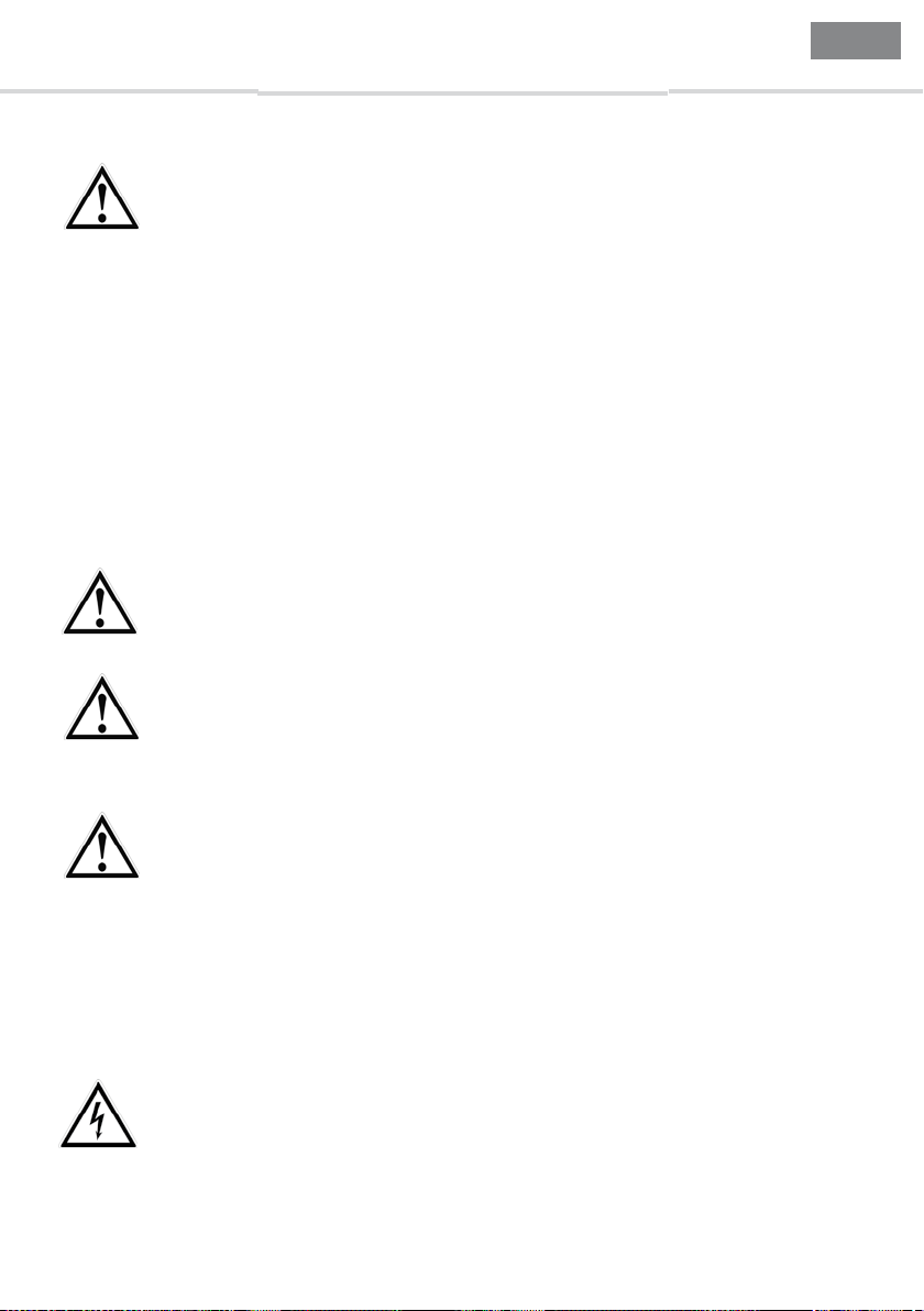
WARNUNG!
… weist auf eine möglicherweise gefährliche Situation hin, die zum Tod oder zu schweren
Verletzungen führen kann, wenn sie nicht gemieden wird.
VORSICHT!
… weist auf eine möglicherweise gefährliche Situation hin, die zu geringfügigen oder leichten Verletzungen bzw. Sach- und Umweltschäden führen kann, wenn sie nicht gemieden
wird.
Information
… hebt nützliche Tipps und Empfehlungen sowie Informationen für einen ezienten und
störungsfreien Betrieb hervor.
GEFAHR!
… kennzeichnet Gefährdungen durch elektrischen Strom. Bei Nichtbeachtung der Sicherheitshinweise besteht die Gefahr schwerer oder tödlicher Verletzungen.
8013875/ZZV7/2018-06-26 © SICK AG • Temperatursensoren • Deutschland • Alle Rechte vorbehalten
3
Page 4

D
Betriebsanleitung TCT
Produktbeschreibung / Aufbau
Die Widerstandsthermometer vom Typ TCT bestehen aus einem Schutzrohr mit festem Prozessanschluss und werden direkt in den Prozess eingeschraubt. Sie sind stoß- und vibrationsfest aufgebaut
und alle elektrischen Bauteile sind gegen Spritzwasser geschützt. Die elektrische Kontaktierung
erfolgt mittels DIN-Winkelstecker oder Rundsteckverbinder M12x1.
Untersuchen Sie die Geräte auf eventuell entstandene Transportschäden.
Sind oensichtlich Schäden vorhanden, teilen Sie dies dem Transportunternehmen und
SICK unverzüglich mit.
Die nachfolgenden Einbau- und Betriebshinweise haben wir mit Sorgfalt zusammengestellt.
Es ist jedoch nicht möglich, alle erdenklichen Anwendungsfälle zu berücksichtigen. Sollten Sie
Hinweise für Ihre spezielle Aufgabenstellung vermissen, können Sie hier weitere Informationen
nden:
■
Über unsere Internet-Adresse www.sick.com
2. Sicherheit
WARNUNG!
Vor Montage, Inbetriebnahme und Betrieb sicherstellen, dass das richtige Thermometer
hinsichtlich Messbereich, Ausführung und spezischen Messbedingungen ausgewählt
wurde.
2. Sicherheit
Bei Nichtbeachten können schwere Körperverletzungen und/oder Sachschäden auftreten.
Weitere wichtige Sicherheitshinweise benden sich in den einzelnen Kapiteln dieser
Betriebsanleitung.
2.1 Bestimmungsgemäße Verwendung
Diese Widerstandsthermometer dienen zur Temperaturmessung in industriellen Anwendungen.
Das Gerät ist ausschließlich für den hier beschriebenen bestimmungsgemäßen Verwendungszweck
konzipiert und konstruiert und darf nur dementsprechend verwendet werden.
Die technischen Spezikationen in dieser Betriebsanleitung sind einzuhalten. Eine unsachgemäße
Handhabung oder ein Betreiben des Gerätes außerhalb der technischen Spezikationen macht die
sofortige Stilllegung erforderlich.
Wird das Gerät von einer kalten in eine warme Umgebung transportiert, so kann durch Kondensatbildung eine Störung der Gerätefunktion eintreten. Vor einer erneuten Inbetriebnahme die Angleichung
der Gerätetemperatur an die Raumtemperatur abwarten.
Ansprüche jeglicher Art aufgrund von nicht bestimmungsgemäßer Verwendung sind ausgeschlossen.
4 8013875/ZZV7/2018-06-26 © SICK AG • Temperatursensoren • Deutschland • Alle Rechte vorbehalten
Page 5
D
TCT Betriebsanleitung
2.2 Personalqualikation
WARNUNG!
Verletzungsgefahr bei unzureichender Qualikation!
Unsachgemäßer Umgang kann zu erheblichen Personen- und Sachschäden führen.
■
Die in dieser Betriebsanleitung beschriebenen Tätigkeiten nur durch Fachpersonal
nachfolgend beschriebener Qualikation durchführen lassen.
■
Unqualiziertes Personal von den Gefahrenbereichen fernhalten.
Fachpersonal
Das Fachpersonal ist aufgrund seiner fachlichen Ausbildung, seiner Kenntnisse der Mess- und
Regelungstechnik und seiner Erfahrungen sowie Kenntnis der landesspezischen Vorschriften,
geltenden Normen und Richtlinien in der Lage, die beschriebenen Arbeiten auszuführen und mögliche Gefahren selbstständig zu erkennen.
Spezielle Einsatzbedingungen verlangen weiteres entsprechendes Wissen, z. B. über agressive
Medien.
2.3 Besondere Gefahren
WARNUNG!
Bei gefährlichen Messstoen wie z. B. Sauersto, Acetylen, brennbaren oder giftigen
Stoen, sowie bei Kälteanlagen, Kompressoren etc. müssen über die gesamten allgemei-
nen Regeln hinaus die einschlägigen Vorschriften beachtet werden.
2. Sicherheit
WARNUNG!
Mechanische Belastungen der elektrischen Anschlüsse und der Gehäuse sind zu
vermeiden. Die maximalen Temperaturen von +150 °C bzw. +250 °C (je nach Konguration) dürfen nicht überschritten werden. Alle Anschlüsse dürfen nur im drucklosen und
abgekühlten Zustand geönet werden.
WARNUNG!
Schutz vor elektrostatischer Entladung (ESD) erforderlich! Die ordnungsgemäße Verwen-
dung geerdeter Arbeitsächen und persönlicher Armbänder ist bei Arbeiten mit oenen
Schaltkreisen (Leiterplatten) erforderlich, um die Beschädigung empndlicher elektroni-
scher Bauteile durch elektrostatische Entladung zu vermeiden.
Für ein sicheres Arbeiten am Gerät muss der Betreiber sicherstellen,
■
dass eine entsprechende Erste-Hilfe-Ausrüstung vorhanden ist und bei Bedarf jederzeit Hilfe zur Stelle ist.
■
dass das Bedienpersonal regelmäßig in allen zutreenden Fragen von Arbeitssicherheit, Erste-Hilfe und Umweltschutz unterwiesen wird, sowie die Betriebsanleitung und
insbesondere die darin enthaltenen Sicherheitshinweise kennt.
GEFHAR!
Lebensgefahr durch elektrischen Strom
Bei Berührung mit spannungsführenden Teilen besteht unmittelbare Lebensgefahr.
■
Einbau und Montage des elektrischen Gerätes dürfen nur durch das Elektrofachpersonal erfolgen.
8013875/ZZV7/2018-06-26 © SICK AG • Temperatursensoren • Deutschland • Alle Rechte vorbehalten
5
Page 6
D
Betriebsanleitung TCT
■
Bei Betrieb mit einem defekten Netzgerät (z. B. Kurzschluss von Netzspannung zur
Ausgangsspannung) können am Gerät lebensgefährliche Spannungen auftreten!
WARNUNG!
Messstoreste in und an ausgebauten Geräten können zur Gefährdung von Personen,
Umwelt und Einrichtung führen. Ausreichende Vorsichtsmaßnahmen ergreifen.
Dieses Gerät nicht in Sicherheits- oder in Not-Aus-Einrichtungen benutzen. Fehlerhafte
Anwendungen des Gerätes können zu Verletzungen führen.
Am Gerät können im Fehlerfall aggressive Medien mit extremer Temperatur und unter
hohem Druck oder Vakuum anliegen.
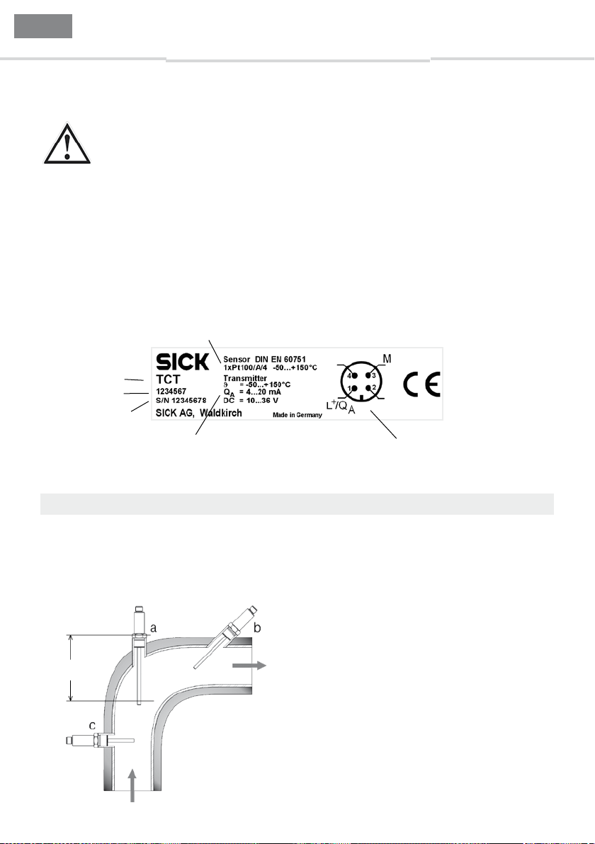
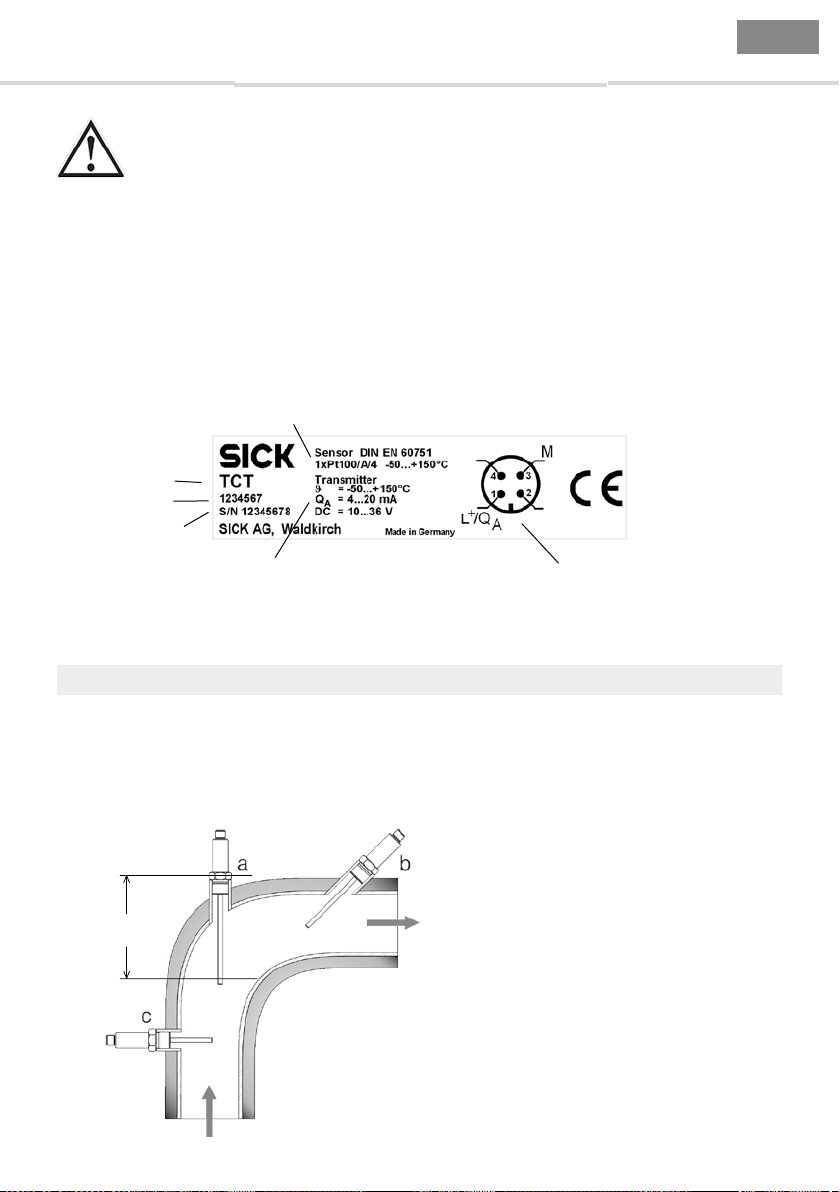
2.4 Beschilderung / Sicherheitskennzeichnungen
3. Montage und Maßzeichnungen
Typenschild
Artikelnummer
Seriennummer
Typ
Messumformer (optional)
■
Messbereich (hier: -50 ... + 150 °C)
■
Ausgangssignal (4 ... 20 mA)
■
Versorgungsspannung (10 ... 36 V)
Messelement
■
Anzahl und Art des Sensors (1 x Pt100)
■
Genauigkeitsklasse (A)
■
Verdrahtungskonguration (4-Leiter-Schaltung)
■
Zulässiger Temperatureinsatzbereich (hier: -50 ... + 150 °C)
Anschlussdiagramm (hier: M12x1)
3. Montage und Maßzeichnungen
Diese Widerstandsthermometer sind vorgesehen zum direkten Einschrauben in den Prozess. Einbaulänge sowie Strömungsgeschwindigkeit und Viskosität des Prozessmediums können sich reduzierend
auf die max. Schutzrohrbelastung auswirken.
Einbaubeispiele
Angaben zu den Einschraublöchern
entnehmen Sie bitte der DIN 3852
bzw. der ANSI B 1.20 für NPT-Gewinde.
Einbaulänge L
Installation an Rohren
a am Winkelstück
b in kleinerem Rohr, geneigt
c senkrecht zur Strömungsrichtung
Für Prozesstemperaturen > 150 °C
sind Varianten ohne Prozessanschluss
und Varianten mit Klemmverschraubung so zu montieren, dass der
Abstand M zwischen Gehäuseunterseite und Einbauebene mindestens 70
mm beträgt (siehe Abmessungen).
6 8013875/ZZV7/2018-06-26 © SICK AG • Temperatursensoren • Deutschland • Alle Rechte vorbehalten
Page 7
D
6014
Alle Maße in mm
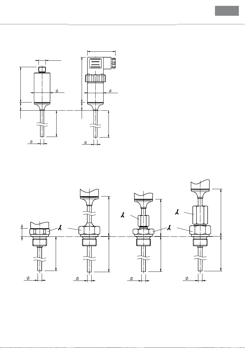
Mit Rundsteckverbinder M12x1 Mit Winkelstecker (DIN EN 175301-803 A)
Gewindeanschluss,
Gewindeanschluss,
Klemmverschraubung Schutzrohr mit Gewinde
TCT Betriebsanleitung
Gehäuse, ohne Prozessanschluss
M12x1
3. Montage und Maßzeichnungen
47
76
27
14
L
D
D
27
L
Prozessanschlüsse, zylindrische Gewinde
bis 150 °C
12
L
bis 250 °C
27
70
L
14
M
L
19
27
70
L
D
D
D
8013875/ZZV7/2018-06-26 © SICK AG • Temperatursensoren • Deutschland • Alle Rechte vorbehalten
D
Alle Maße in mm
7
Page 8
D
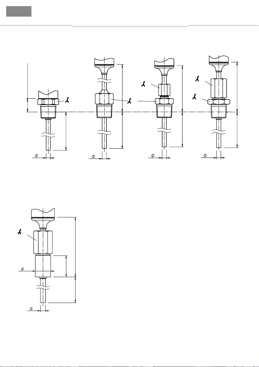
1/4" NPT - 15 mm
Alle Maße in mm
Betriebsanleitung TCT
Prozessanschlüsse, konische Gewinde
Gewindeanschluss,
bis 150 °C
3. Montage und Maßzeichnungen
Gewindeanschluss,
bis 250 °C
Klemmverschraubung Schutzrohr mit Gewinde
1/2" NPT - 20 mm
D
27
L
D
70
22
L
Prozessanschluss, Schutzrohr mit Einschweißstutzen
19
70
14
D
19
M
27
L
D
Alle Maße in mm
70
L
18
D
25
L
8 8013875/ZZV7/2018-06-26 © SICK AG • Temperatursensoren • Deutschland • Alle Rechte vorbehalten
Page 9
D
1
TCT Betriebsanleitung
4. Anschlussart und -schema
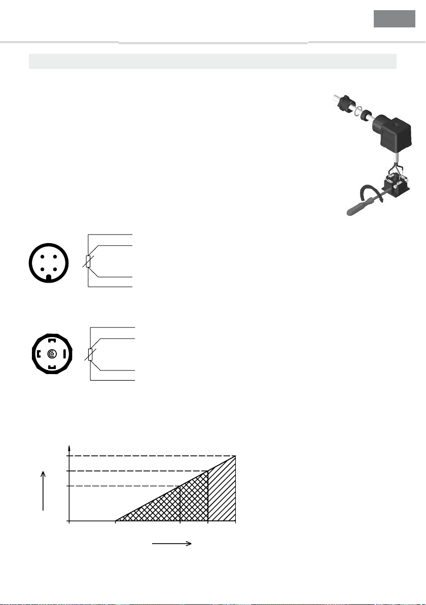
4.1 Montage des Winkelsteckers (Ausführung mit Winkelstecker DIN EN 175301-803 A)
Bei Litzenadern empfehlen wir das Verwenden von gecrimpten Aderendhülsen.
Zum Sicherstellen der Schutzart IP 65:
■
Immer die Silikon-Dichtung verwenden
■
Verriegelungsschraube anziehen
■
Kabeleinführung sorgfältig ausführen
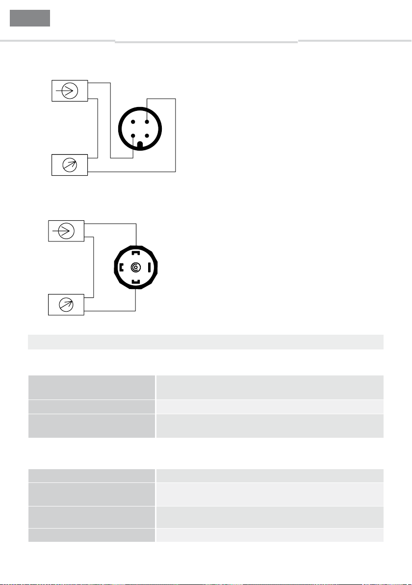
4.2 Ausgangssignal Pt100
Anschluss an Konstantstromquelle, Messstrom 0,3 mA bis 1,0 mA.
Rundsteckverbinder M12x1, Ausgangssignal Pt100
4. Anschlussart und -schema
43
1
2
ϑ
2
3
4
Winkelstecker (DIN EN 175 301-803 A) M12x1, Ausgangssignal Pt100
4
1
4
3
ϑ
2
2
3
1
4.3 Ausgangssignal 4 mA ... 20 mA, 2-Leiter (Messumformer)
Bürdendiagramm:
1182
909
636
in Ω
A
0 10 24 30 36
Bürde R
Spannung L+ in V
Die zulässige Bürde hängt ab von der
Spannung der Schleifenversorgung.
8013875/ZZV7/2018-06-26 © SICK AG • Temperatursensoren • Deutschland • Alle Rechte vorbehalten
9
Page 10
D
Betriebsanleitung TCT
Rundsteckverbinder M12x1, Ausgangssignal 4 mA ... 20 mA
L+/ Q
+
A
-
4
1
-
M
+
Winkelstecker (DIN EN 175301-803 A), Ausgangssignal 4 mA ... 20 mA
L+/ Q
+
A
-
1
3
2
5. Technische Daten
3
2
-
+
M
5. Technische Daten
Merkmale
Messbereiche –50 °C ... +150 °C
–50 °C ... +250 °C
Messelement Pt100
Ausgangssignale und maximal
zulässige Bürde R
A
Performance
Genauigkeit des Messelements Klasse A nach IEC 60751
Genauigkeit des optionalen
Messumformers
Linearität des optionalen Messumformers
Ansprechzeit t
10 8013875/ZZV7/2018-06-26 © SICK AG • Temperatursensoren • Deutschland • Alle Rechte vorbehalten
Pt100, 4-Leiter,
4 mA ... 20 mA, 2-Leiter (RA ≤ (L+ – 9 V) / 0,023 A [Ohm])
≤ ± 1,0 % der Spanne
≤ ± 0,1 % der Spanne
< 5 s / t90 < 10 s (Durchmesser des Messfühlers 6 mm)
50
Page 11

D
TCT Betriebsanleitung
Mechanik/Elektrik
5. Technische Daten
Prozessanschlüsse
1)
Ohne Prozessanschluss,
Gewinde G 1/4 B, Gewinde G 1/2 B,
Gewinde 1/4'' NPT, Gewinde 1/2'' NPT,
Klemmverschraubung G 1/4 B, CrNi-Stahl-Klemmring,
Klemmverschraubung G 1/2 B, CrNi-Stahl-Klemmring,
Klemmverschraubung 1/4'' NPT, CrNi-Stahl-Klemmring,
Klemmverschraubung 1/2'' NPT, CrNi-Stahl-Klemmring,
Klemmverschraubung G 1/4 B, PTFE-Klemmring,
Klemmverschraubung G 1/2 B, PTFE-Klemmring,
Klemmverschraubung 1/4'' NPT, PTFE-Klemmring,
Klemmverschraubung 1/2'' NPT, PTFE-Klemmring,
Schutzrohr G 1/4 B,
Schutzrohr G 1/2 B,
Schutzrohr 1/4'' NPT,
Schutzrohr 1/2'' NPT,
Schutzrohr Schweißstutzen Durchmesser 18 mm
Einbaulängen/Durchmesser des
Messfühlers
2)
25 mm / 3 mm
50 mm / 3 mm
100 mm / 6 mm
150 mm / 6 mm
250 mm / 6 mm
350 mm / 6 mm
Druckbelastbarkeit
3)
Max. 40 bar bei mitgelieferter Klemmverschraubung mit PTFEKlemmring,
Max. 100 bar bei mitgelieferter Klemmverschraubung mit
Edelstahl-Klemmring,
Max. 120 bar bei Gewinde-Prozessanschluss,
Max. 220 bar bei Schutzrohrvarianten
Gehäusematerial Edelstahl 1.4571
Medienberührende Werkstoe Edelstahl 1.4571
Anschlussart/Schutzart
4)
Stecker M12x1, 4-polig, IP 67,
Winkelstecker (DIN EN 175301-803 A), 4-polig, IP 65
Messstrom 0,3 mA ... 1,0 mA (bei Variante mit Ausgangssignal Pt100)
Versorgungsspannung 10 V DC ... 36 V DC bei Variante mit Messumformer 4 mA ... 20 mA
Maximale Stromaufnahme Ca. 30 mA bei Variante mit Messumformer 4 mA ... 20 mA
1)
Die Klemmverschraubungen mit PTFE-Klemmring sind bis zu einer Temperatur von +150 °C geeignet.
2)
Für Messbereich –50 °C ... +250 °C Einbaulängen ab 100 mm erforderlich.
3)
Druckbelastbarkeit bei Raumtemperatur.
4)
Schutzart IP nach IEC 60529. Die angegebenen Schutzarten gelten nur im gesteckten Zustand mit Leitungssteckern entsprechender Schut-
zart.
8013875/ZZV7/2018-06-26 © SICK AG • Temperatursensoren • Deutschland • Alle Rechte vorbehalten
11
Page 12

D
Betriebsanleitung TCT
Elektrische Sicherheit Schutzklasse: III,
Gewicht Ca. 145 g (je nach Ausführung)
Umgebungsdaten
Umgebungstemperatur –40 °C ... +85 °C für Variante mit Messumformer 4 mA ... 20 mA,
Lager- und Transporttemperatur –40 °C ... +85 °C
Schockfestigkeit nach IEC 60751 500 g
Vibrationsfestigkeit nach IEC
60751
6. Wartung
Die hier beschriebenen Thermometer sind absolut wartungsfrei!
Die Elektronik ist vollständig vergossen und enthält keinerlei Bauteile, welche repariert oder ausgetauscht werden könnten.
6. Wartung
Isolationsspannung: 500 V AC,
Verpolschutz der Variante mit Messumformer 4 mA ... 20 mA: L+
gegen M
–40 °C ... +85 °C für Variante mit Ausgangssignal Pt100 und
Winkelstecker (DIN EN 175301-803 A),
–40 °C ... +125 °C für Variante mit Ausgangssignal Pt100 und
Rundsteckverbinder M12x1
3 g
7. Rücksendung
Prozess Material Zertikat (Unbedenklichkeitserklärung im Servicefall)
Spülen bzw. säubern Sie ausgebaute Geräte vor der Rücksendung, um unsere Mitarbeiter und die
Umwelt vor Gefährdung durch anhaftende Messstoreste zu schützen.
Eine Rücksendung kann nur sicher erfolgen, wenn die vollständig ausgefüllte Unbedenklichkeitserklärung vorliegt. Eine solche Erklärung beinhaltet alle Materialien, welche mit
dem Gerät in Berührung kamen, auch solche, die zu Testzwecken, zum Betrieb oder zur
Reinigung eingesetzt wurden. Die Unbedenklichkeitserklärung ist über unsere InternetAdresse (www.sick.com) verfügbar.
12 8013875/ZZV7/2018-06-26 © SICK AG • Temperatursensoren • Deutschland • Alle Rechte vorbehalten
Page 13

D
TCT Betriebsanleitung
8. Lagerung, Entsorgung
Ergreifen Sie bei Lagerung und Entsorgung Vorsichtsmaßnahmen für Messstoreste in und an ausgebauten Temperatursensoren. Wir empfehlen eine geeignete und sorgfältige Reinigung. Messstoreste
können zur Gefährdung von Menschen, Umwelt und Einrichtung führen!
Entsorgung
Entsorgen Sie Gerätekomponenten und Verpackungsmaterialien entsprechend den einschlägigen
landesspezischen Abfallbehandlungs- und Entsorgungsvorschriften des Anliefergebietes.
8. Lagerung, Entsorgung
8013875/ZZV7/2018-06-26 © SICK AG • Temperatursensoren • Deutschland • Alle Rechte vorbehalten
13
Page 14

EN
Operating instructions TCT
1. General Information
■
The instrument described in the operating instructions has been manufactured using state-oftheart technology. All components are subject to stringent quality and environmental criteria during
production. Our management systems are certied to ISO 9001 and ISO 14001.
■
These operating instructions contain important information on handling the instrument. Working
safely requires that all safety instructions and work instructions are observed.
■
Observe the relevant local accident prevention regulations and general safety regulations for the
instrument‘s range of use.
■
The operating instructions are part of the instrument and must be kept in the immediate vicinity of
the instrument and readily accessible to skilled personnel at any time.
■
Skilled personnel must have carefully read and understood the operating instructions, prior to
beginning any work.
■
The manufacturer‘s liability is void in the case of any damage caused by using the product contrary
to its intended use, non-compliance with these operating instructions, assignment of insuciently
qualied skilled personnel or unauthorised modications to the instrument.
■
The general terms and conditions, contained in the sales documentation, shall apply.
■
Subject to change without notice.
■
Further informations:
www.sick.de / www.sick.com
E-Mail: info@sick.de
1. General Information
Explanation of symbols
WARNING!
… indicates a potentially dangerous situation, which can result in serious injury or
death, if not avoided.
CAUTION!
… indicates a potentially dangerous situation, which can result in light injuries or
damage to equipment or the environment, if not avoided.
Information
… points out useful tips, recommendations and information for ecient and troublefree
operation.
DANGER!
… identies hazards caused by electric power. Should the safety instructions not be
observed, there is a risk of serious or fatal injury.
14 8013875/ZZV7/2018-06-26 © SICK AG • Temperature • Germany • Subject to change without notic
Page 15

EN
TCT Operating instructions
Product description / design
Model TCT resistance thermometers consist of a thermowell with a xed process connection,
and are screwed directly into the process. They are designed to be shock and vibration proof and
the electrical components are protected against splash water. The electrical connection is made via a
DIN L-plug or an M12x1 circular connector
Please inspect the instruments for possible damage during transportation.
Should there be any obvious damage, please inform the transport company
and SICK without dela
The following mounting and operating information has been compiled with care.
However, it is not possible to foresee all eventualities. If you cannot nd information on your
specic problem, further information can be found
■
Via our internet address www.sick.com
2. Safety instructions
WARNING!
Before installation, commissioning and operation, ensure that the appropriate thermome-
ter has been selected in terms of measuring range, design and specic measuring
conditions.
2. Safety instructions
Non-observance can result in serious injury and/or damage to equipment.
Further important safety instructions can be found in the individual chapters of these
operating instructions.
2.1 Intended use
These resistance thermometers are used for temperature measurement in industrial applications. The
instrument has been designed and built solely for the intended use described here, and may only be used
accordingly.
The technical specications contained in these operating instructions must be observed. Improper
handling or operation of the instrument outside of its technical specications requires the instrument
to be shut down immediately.
If the instrument is transported from a cold into a warm environment, the formation of condensation
may result in the instrument malfunctioning. Before putting it back into operation, wait for the
instrument temperature and the room temperature to equalize.
The manufacturer shall not be liable for claims of any type based on operation contrary to the
intended use.
8013875/ZZV7/2018-06-26 © SICK AG • Temperature • Germany• Subject to change without notic
15
Page 16

EN
Operating instructions TCT
2.2 Personnel qualication
WARNING!
Risk of injury should qualication be insucient!
Improper handling can result in considerable injury and damage to equipment.
■
The activities described in these operating instructions may only be carried out by
skilled personnel who have the qualications described below.
■
Keep unqualied personnel away from hazardous areas.
Skilled personnel
Skilled personnel are understood to be personnel who, based on their technical training, knowledge
of measurement and control technology and on their experience and knowledge of country-specic
regulations, current standards and directives, are capable of carrying out the work described and
independently recognizing potential hazards.
Special operating conditions require further appropriate knowledge, e.g. of aggressive media.
2.3 Special hazards
WARNING!
For hazardous media such as oxygen, acetylene, ammable or toxic gases or liquids, and
refrigeration plants, compressors, etc., in addition to all standard regulations, the appropriate existing codes or regulations must also be followed.
WARNING!
Mechanical load of electrical connectors and housing is to be avoided.
The maximum temperatures of +150 °C and +250°C (depending on conguration) must
not be exceeded.
All connections shall only be opened at room temperature and in unpressurized conditions.
2. Safety instructions
WARNING!
Protection from electrostatic discharge (ESD) required. The proper use of grounded
work surfaces and personal wrist straps is required when working with exposed circuitry
(printed circuit boards), in order to to prevent static discharge from damaging sensitive
electronic components.
To ensure safe working on the instrument, the operating company must ensure
■
that suitable rst-aid equipment is available and aid is provided whenever required.
■
that the operating personnel are regularly instructed in all topics regarding work
safety, rst aid and environmental protection and knows the operating instructions
and, in particular, the safety instructions contained therein.
DANGER!
Danger of death caused by electric current
Upon contact with live parts, there is a direct danger of death.
■
Electrical instruments may only be installed and mounted by skilled electrical personnel.
■
Operation using a defective power supply unit (e.g. short circuit from the mains voltage
to the output voltage) may result in life-threatening voltages at the instrument!
16 8013875/ZZV7/2018-06-26 © SICK AG • Temperature • Germany • Subject to change without notic
Page 17
EN
TCT Operating instructions
WARNING!
Residual media in and at dismounted instruments can result in a risk to persons, the
environment and equipment. Take sucient precautionary measures.
Do not use this instrument in safety or Emergency Stop devices. Incorrect use of the
instrument can result in injury.
Should a failure occur, aggressive media with extremely high temperature and under high
pressure or vacuum may be present at the instrument.
2.4 Labelling / safety marks
3. Installation and dimensions
Product label
Part number
Serial number
Type
Transmitter (optional)
■
Measuring range (here: -50 ... + 150 °C)
■
Output signal (4 ... 20 mA)
■
Supply voltage (10 ... 36 V)
Sensor element
■
Number and type of sensor (1 x Pt100)
■
Accuracy class (A)
■
Wiring conguration (4-wire circuit)
■
Permissible operating temperature range (here: -50 ... + 150 °C)
Connection diagram (here: M12x1)
3. Installation and dimensions
These resistance thermometers are provided for tting directly into the process. The insertion length
and the ow velocity as well as the viscosity of the process medium may reduce the maximum load
capacity of the thermowell.
Installation examples
For information on tapped holes,
please refer to DIN 3852 or ANSI B
1.20 for NPT threads.
Insertion length L
For process temperatures > 150
°C variants without process
connection and variants with
compression tting are to be
installed such that the distance
Installation in pipes
a in the elbow tting
b in a smaller, inclined pipe
c at right angles to the ow direction
8013875/ZZV7/2018-06-26 © SICK AG • Temperature • Germany• Subject to change without notic
M between the lower edge of the
housing and the installation level
is at least 70 mm (see dimensions
below).
17
Page 18

EN
60
14
With circular connector M12x1With L-connector (DIN EN 175301-803 A)
Thread, up to 150 °C Thread, up to 250 °C Compression fittingThreaded thermowell
Operating instructions TCT
Housing dimensions, without process connection
M12x1
(2.36)
27
(
1.06)
3. Installation and dimensions
47
(1.85)
76
(3.00)
27
(
1.06)
(0.55)
L
D
14
(0.55)
D
L
All dimensions in mm (inch)
Process connections, cylindrical threads
27
(1.06)
19
(0.75)
14
(2.76)
L
(0.55)
M
L
D
12
(0.47)
27
(1.06)
70
L
D
D
70
(2.76)
L
D
All dimensions in mm (inch)
18 8013875/ZZV7/2018-06-26 © SICK AG • Temperature • Germany • Subject to change without notic
Page 19

EN
1/2" NPT - 20 mm (0.79"
1/4" NPT - 15 mm (0.59")
Thread, up to 150 °C Thread, up to 250 °C Compression fittingThreaded thermowell
TCT Operating instructions
Process connections, conical threads
27
(1.06)
)
3. Installation and dimensions
14
22
(0.87)
(0.55)
70
(2.75)
19
(0.75)
M
27
(1.06)
70
(2.76)
L
D
D
L
D
L
D
All dimensions in mm (inch)
Process connection, weld-in thermowell
19
(0.75)
70
(2.75)
18
(
0.71)
D
25
(0.98)
L
L
All dimensions in mm (inch)
8013875/ZZV7/2018-06-26 © SICK AG • Temperature • Germany• Subject to change without notic
19
Page 20

EN
1
Operating instructions TCT
4. Connection type and diagram
4.1 Assembly of L-connector (version with L-plug DIN EN 175301-803 A)
We recommend the use of crimped connector sleeves in the case of exible
leads.
To ensure the IP 65 enclosure rating:
■
Always use the silicone gasket
■
Tighten the locking screw
■
Make sure to insert the cables carefully
4.2 Output signal Pt100
Connection to constant current power supply, measuring current 0.3 mA to 1.0 mA
Plug M12x1, output signal Pt100
4. Connection type and diagram
43
1
2
ϑ
2
3
4
L-connector (DIN EN 175301-803 A), output signal Pt100
4
1
4
3
ϑ
2
2
3
1
4.3 Output signal 4 mA ... 20 mA, 2-wire (transmitter)
Load diagram
1182
909
636
in Ω
A
0 10 24 30 36
Load R
Voltage L+ in V
The allowed resistive load depends
on the voltage of the loop power
supply.
20 8013875/ZZV7/2018-06-26 © SICK AG • Temperature • Germany • Subject to change without notic
Page 21

EN
+
L+/ Q
TCT Operating instructions
Plug M12x1, output signal 4 mA ... 20 mA
L+/ Q
+
A
-
4
1
-
M
L-connector (DIN EN 175301-803 A), output signal 4 mA ... 20 mA
5. Technical data
3
2
+
A
-
1
3
2
-
M
+
5. Technical data
Features
Measuring ranges –50 °C ... +150 °C
–50 °C ... +250 °C
Sensor element Pt100
Signal outputs and maximum
ohmic load R
A
Performance
Accuracy of sensor element Class A according to IEC 60751
Accuracy of optional transmitter ≤ ± 1.0 % of span
Linearity of optional transmitter ≤ ± 0.1 % of span
Response time t
Pt100, 4-wire,
4 mA ... 20 mA, 2-wire (RA ≤ (L+ – 9 V) / 0.023 A [Ohm])
< 5 s / t90 < 10 s (diameter of probe 6 mm)
50
8013875/ZZV7/2018-06-26 © SICK AG • Temperature • Germany• Subject to change without notic
21
Page 22

EN
Operating instructions TCT
Mechanics/electronics
Process connections
Insertion length/diameter of
2)
probe
Pressure resistance
1)
3)
Housing material Stainless steel 1.4571
Wetted parts Stainless steel 1.4571
Electrical connection/enclosure
4)
rating
Measuring current 0.3 mA ... 1.0 mA (for variant with output signal Pt100)
Supply voltage 10 V DC ... 36 V DC for variant with transmitter 4 mA ... 20 mA
Maximum current consumption Ca. 30 mA for variant with transmitter 4 mA ... 20 mA
Electrical safety Protection class: III,
Weight Ca. 145 g (depending on conguration)
1) The compression ttings with PTFE ferrule are suited for temperatures up to +150 °C.
2)
For measuring range –50 °C ... +250 °C insertion lengths from 100 mm required.
3)
Pressure resistance at room temperature.
4)
Enclosure rating IP per IEC 60529. The enclosure rating classes specied only apply while the pressure transmitter is
connected with female connectors that provide the corresponding enclosure rating.
5. Technical data
Without process connection,
Thread G 1/4 B, Thread G 1/2 B,
Thread 1/4'' NPT, Thread 1/2'' NPT,
Compression tting G 1/4 B, CrNi stainless steel ferrule,
Compression tting G 1/2 B, CrNi stainless steel ferrule,
Compression tting 1/4'' NPT, CrNi stainless steel ferrule,
Compression tting 1/2'' NPT, CrNi stainless steel ferrule,
Compression tting G 1/4 B, PTFE ferrule,
Compression tting G 1/2 B, PTFE ferrule,
Compression tting 1/4'' NPT, PTFE ferrule,
Compression tting 1/2'' NPT, PTFE ferrule,
Thermowell G 1/4 B, Thermowell G 1/2 B,
Thermowell 1/4'' NPT, Thermowell 1/2'' NPT,
Thermowell weld-in diameter 18 mm
25 mm / 3 mm
50 mm / 3 mm
100 mm / 6 mm
150 mm / 6 mm
250 mm / 6 mm
350 mm / 6 mm
Max. 40 bar with supplied compression tting with PTFE ferrule,
Max. 100 bar with supplied compression tting with stainless steel
ferrule,
Max. 120 bar with threaded process connection,
Max. 220 bar with variants with thermowell
Plug M12x1, 4-pin, IP 67,
L-connector (DIN EN 175301-803 A), 4 pin, IP 65
Dielectric strength: 500 V AC,
Reverse polarity protection of variant with transmitter
4 mA ... 20 mA: L
+
towards M
22 8013875/ZZV7/2018-06-26 © SICK AG • Temperature • Germany • Subject to change without notic
Page 23

EN
TCT Operating instructions
Ambient data
Ambient temperature –40 °C ... +85 °C for variant with transmitter 4 mA ... 20 mA,
Storage and transport temperature
Shock resistance according to IEC
60751
Vibration resistance according to
IEC 60751
6. Maintenance
The Thermometer described here is completely maintenance free!
The electronics are completely encapsulated and do not contain any components that could be
repaired or replaced.
7. Returned goods
6. Maintenance
–40 °C ... +85 °C for variant with output signal Pt100 and Lconnector (DIN EN 175301-803 A),
–40 °C ... +125 °C for variant with output signal Pt100 and circular plug M12x1
–40 °C ... +85 °C
500 g
3 g
Process material certicate (Non-risk declaration for returned goods)
Purge / clean dismounted instruments before returning them in order to protect our employees and the environment from any hazard caused by adherent remaining media.
Service of instruments can only take place safely when a non-risk declaration has been
submitted and fully lled-in. This non-risk decalaration contains information on all materials with which the instrument has come into contact, either through installation, test
purposes, or cleaning. You can nd the non-risk declaration on our internet site (www.sick.
com).
8. Storage, disposal
When storing or disposing of the pressure transmitter, take precautions with regard to remaining
media in and at the removed temperature sensor. We recommend cleaning the sensor properly and
carefully. Remaining media at the device may be hazardous or toxic!
Disposal
Dispose of the instrument components and packaging materials in accordance with the relevant
country-specic regulations for waste treatment and disposal of the region to which the device is
supplied.
8013875/ZZV7/2018-06-26 © SICK AG • Temperature • Germany• Subject to change without notic
23
Page 24

8013875/ZZV7/2018-06-26 ∙ LW/KE (2018-06) ∙ A5 sw int48
Australia
Phone +61 (3) 9457 0600
1800 33 48 02 – tollfree
Austria
Phone +43 (0) 2236 62288-0
Belgium/Luxembourg
Phone +32 (0) 2 466 55 66
Brazil
Phone +55 11 3215-4900
Canada
Phone +1 905.771.1444
Czech Republic
Phone +420 2 57 91 18 50
Chile
Phone +56 (2) 2274 7430
China
Phone +86 20 2882 3600
Denmark
Phone +45 45 82 64 00
Finland
Phone +358-9-25 15 800
France
Phone +33 1 64 62 35 00
Germany
Phone +49 (0) 2 11 53 01
Hong Kong
Phone +852 2153 6300
Hungary
Phone +36 1 371 2680
India
Phone +91-22-6119 8900
Israel
Phone +972-4-6881000
Italy
Phone +39 02 27 43 41
Japan
Phone +81 3 5309 2112
Malaysia
Phone +603-8080 7425
Mexico
Phone +52 (472) 748 9451
Netherlands
Phone +31 (0) 30 229 25 44
New Zealand
Phone +64 9 415 0459
0800 222 278 – tollfree
Norway
Phone +47 67 81 50 00
Poland
Phone +48 22 539 41 00
Romania
Phone +40 356-17 11 20
Russia
Phone +7 495 283 09 90
Singapore
Phone +65 6744 3732
Slovakia
Phone +421 482 901 201
Slovenia
Phone +386 591 78849
South Africa
Phone +27 (0)11 472 3733
South Korea
Phone +82 2 786 6321
Spain
Phone +34 93 480 31 00
Sweden
Phone +46 10 110 10 00
Switzerland
Phone +41 41 619 29 39
Taiwan
Phone +886-2-2375-6288
Thailand
Phone +66 2 645 0009
Turkey
Phone +90 (216) 528 50 00
United Arab Emirates
Phone +971 (0) 4 88 65 878
United Kingdom
Phone +44 (0)17278 31121
USA
Phone +1 800.325.7425
Vietnam
Phone +65 6744 3732
Detailed addresses and further
locations at www.sick.com
SICK AG | Waldkirch | Germany | www.sick.com
 Loading...