

Page 1

STR1
Draft 2016-10-19
Safety switch
O P E R A T I N G I N S T R U C T I O N S
Page 2

Described product
Draft 2016-10-19
STR1
Manufacturer
SICK A
G
Erwin-Sick
-Str. 1
79183 Waldkirch
Germany
Legal information
This work is prot
ected by copyright. Any rights derived from the copyright shall be
reserved for SICK AG. Reproduction of this document or parts of this document is only
permissible within the limits of the legal determination of Copyright Law. Any modifica‐
tion, abridgment or translation of this document is prohibited without the express writ‐
ten permission of SICK AG.
The trademarks stated in this document are the property of their respective owner.
© SICK AG. All rights reserved.
Original document
This document is an or
iginal document of SICK AG.
2
O PE R AT I NG IN S TR U CT I ON S | STR1 8018754/2016-xx-xx | SICK
Subject to change without notice
Page 3

Contents
Draft 2016-10-19
CONTENTS
1 About this document........................................................................ 5
1.1 Function of this document....................................................................... 5
1.2 Scope......................................................................................................... 5
1.3 Target groups and structure of these operating instructions................ 5
1.4 Additional information.............................................................................. 5
1.5 Symbols and document conventions...................................................... 6
2 Safety information............................................................................ 8
2.1 General safety notes................................................................................. 8
2.2 Intended use............................................................................................. 8
2.3 Requirements for the qualification of personnel.................................... 8
3 Product description........................................................................... 10
3.1 Setup and function................................................................................... 10
3.2 Product characteristics............................................................................. 10
4 Project planning................................................................................ 12
4.1 Manufacturer of the machine.................................................................. 12
4.2 Operating entity of the machine.............................................................. 12
4.3 Design........................................................................................................ 13
4.4 Integration into the electrical control...................................................... 13
4.5 Thorough check concept.......................................................................... 17
5 Mounting............................................................................................. 18
5.1 Safety......................................................................................................... 18
5.2 Unpacking.................................................................................................. 18
5.3 Possible mounting types.......................................................................... 18
5.4 Mounting................................................................................................... 20
6 Electrical installation........................................................................ 22
6.1 Safety......................................................................................................... 22
6.2 Notes on cULus......................................................................................... 23
6.3 Device connection (flying leads).............................................................. 24
6.4 Device connection (M12, 5-pin).............................................................. 24
6.5 Device connection (M12, 8-pin).............................................................. 24
6.6 Connecting a cascade.............................................................................. 25
8018754/2016-xx-xx | SICK OP E RA T IN G I N ST R UC T IO N S | STR1
Subject to change without notice
7 Commissioning.................................................................................. 28
7.1 Safety......................................................................................................... 28
7.2 Switching on.............................................................................................. 28
7.3 Teach-in..................................................................................................... 28
7.4 Thorough check........................................................................................ 29
8 Troubleshooting................................................................................. 30
8.1 Safety......................................................................................................... 30
3
Page 4

CONTENTS
Draft 2016-10-19
8.2 Diagnostic LEDs........................................................................................ 30
9 Maintenance...................................................................................... 33
9.1 Cleaning..................................................................................................... 33
9.2 Regular thorough check........................................................................... 33
10 Decommissioning............................................................................. 34
10.1 Protection of the environment................................................................. 34
10.2 Disposal..................................................................................................... 34
11 Technical data.................................................................................... 35
11.1 Technical data........................................................................................... 35
11.2 Dimensional drawings.............................................................................. 38
11.3 Response time and enable time in cascade.......................................... 39
12 Ordering information........................................................................ 40
12.1 Scope of delivery...................................................................................... 40
12.2 STR1 ordering information....................................................................... 40
13 Spare parts......................................................................................... 42
13.1 Actuator..................................................................................................... 42
13.2 Sensors..................................................................................................... 42
14 Accessories........................................................................................ 43
14.1 Connectivity............................................................................................... 43
15 Annex.................................................................................................. 45
15.1 Compliance with EU directives................................................................. 45
15.2 FCC and IC radio approval........................................................................ 46
16 List of figures..................................................................................... 47
17 List of tables....................................................................................... 48
4
O PE R AT I NG IN S TR U CT I ON S | STR1 8018754/2016-xx-xx | SICK
Subject to change without notice
Page 5

1 About this document
Draft 2016-10-19
1.1 Function of this document
These operating instructions contain the information needed during the life cycle of the
safety switch.
ABOUT THIS DOCUMENT 1
They mus
t be made available to all people who work with the safety switch.
1.2 Scope
The operating instructions only apply to the STR1 safety switch with the following infor‐
mation on t
he product packaging: Oper
ating Instructions 8018074.
These operating instructions are included with SICK part number 8018074 (all availa‐
ble languages of this document).
1.3 Target groups and structure of these operating instructions
These operating instructions are intended for the following target groups: project devel‐
oper
s (planner
CE authorized representatives, compliance officers, people who test and approve the
application), operators, and maintenance personnel.
The structure of these operating instructions is based on the life cycle phases of the
safety switch: project planning, mounting, electrical installation, commissioning, opera‐
tion, and maintenance.
In many applications, the target groups consist of the manufacturer and the operating
entity of the machine in which the safety switch is integrated:
Area of responsibility Target group Special chapters of these operating instruc‐
Manufacturer Project developers
Operating entity Operators Troubleshooting, pag
s, developer
(planners, developers,
designer
Installers Mounting, pag
Electricians Electrical inst
Safety experts Project planning, page 12
Maintenance person‐
nel
s, designers), installers, electricians, safety experts (such as
1)
tions
Project planning, page 12
Technical data, page 35
s)
Accessories, page 43
Commissioning, page 28
echnical data, page 35
T
Maint
enance, page 33
Troubleshooting, page 30
Ordering information, page 40
e 18
allation, page 22
e 30
1.4 Additional information
8018754/2016-xx-xx | SICK OP E RA T IN G I N ST R UC T IO N S | STR1
Subject to change without notice
1)
Chapters not listed here are intended for all target groups. All target groups must follow all of the safety
and warning instructions in all c
hapters of the operating instructions!
In other applications, the operating organization is also the manufacturer of the equip‐
ment with the corresponding allocation of t
he target groups.
www.sick.com
The following information is a
vailable on the Internet:
5
Page 6
1 AB
Draft 2016-10-19
OUT THIS DOCUMENT
versions in other languag
•
data sheets and application examples
•
CAD data of drawings and dimensional drawings
•
certificates (e.g. EU declaration of conformity)
•
Guide for Safe Machinery (Six steps to a safe machine)
•
1.5 Symbols and document conventions
The following symbols and conventions are used in this document:
Safety notes and other notes
DANGER
Indicates a situation presenting imminent danger, whic
injuries if not prevented.
WARNING
Indicat
es a situation pr
injuries if not prevented.
CAUTION
Indicates a situation presenting possible danger, whic
injuries if not prevented.
esenting possible danger, whic
es
h will lead to death or serious
h may lead to death or serious
h may lead to moderate or minor
NOTICE
Indicates a situation presenting possible danger, whic
not prevented.
NOTE
Indicates useful tips and recommendations.
Instructions for action
The arrow denot
b
1. The sequence of instructions for action is numbered.
2. Follow the order in which the numbered instructions are given.
✓
The check mark denotes a result of an instruction for action.
LED symbols
These symbols indicate the status of an LED:
The LED is off.
The LED is flashing.
The LED is illuminated continuously.
Terminology
erous state
Dang
es instructions for action.
h may lead to property damage if
6
O PE R AT I NG IN S TR U CT I ON S | STR1 8018754/2016-xx-xx | SICK
A dang
erous state is a status of the machine or facility, where people may be injured.
Protective devices prevent this risk if the machine is operated within its intended use.
The figures in this document always show the dangerous state of the machine as move‐
ment of a machine part. In practice, there are different dangerous states, such as:
Subject to change without notice
Page 7

Machine movements
Draft 2016-10-19
•
Electrical par
•
Visible and invisible beam
•
A combination of multiple hazards
•
ts
ABOUT THIS DOCUMENT 1
8018754/2016-xx-xx | SICK OP E RA T IN G I N ST R UC T IO N S | STR1
Subject to change without notice
7
Page 8

2 SAFETY INFORMATION
Draft 2016-10-19
2 Safety information
2.1 General safety notes
This chapter contains general safety information about the safety switch.
Further infor
chapters.
DANGER
Hazar
In the case of non-compliance, it is possible that the dangerous state of the machine
may not be stopped or not stopped in a timely manner.
b
b
Incorrect installation or manipulation can lead to severe injuries.
2.2 Intended use
The safety switch is a transponder safety switch that is switched in a non-contact man‐
ner by means of actuators, and is suitable f
•
The safety switch must only be used within the limits of the prescribed and specified
technical data and operating conditions at all times.
Incorrect use, improper modification, or manipulation of the safety switch will invalidate
any warranty from SICK AG; in addition, any responsibility and liability of SICK AG for
damage and secondary damage caused by this is excluded.
mation about specific product use situations can be found in the relevant
o lac
d due t
Read this document carefully and ensure that you have fully understood the con‐
tents before you work with the device.
Pay particular attention to all safety notes in this document.
Movable physical guards
f
ectiveness of the protective device
k of ef
or the following applications:
The safety switch is not suitable for certain ambient conditions, including:
Radioactivity (with the exception of natural radioactivity)
•
Vacuum or high pressure
•
High UV exposure
•
In the vicinity of low-frequency RFIDs
•
In the vicinity of magnetic fields
•
The following can impair the function of the safety switch:
Metal subsurfaces or metal in the immediate vicinity (see "Design", page 13)
•
Flying metal chips
•
2.3 Requirements for the qualification of personnel
The safety switch must be configured, mounted, connected, commissioned, and serv‐
iced by qualified safe
Project planning
For project planning, a person is considered competent when he/she has expertise and
experience in the selection and use of protective devices on machines and is familiar
with the relevant technical rules and national work safety regulations.
ty personnel only.
8
O PE R AT I NG IN S TR U CT I ON S | STR1 8018754/2016-xx-xx | SICK
Subject to change without notice
Page 9

SAFETY INFORMATION 2
Draft 2016-10-19
Mechanical mounting, electrical installation, and commissioning
For the task, a per
rience in the relevant field and is sufficiently familiar with the application of the protec‐
tive device on the machine to be able to assess whether it is in an operationally safe
state.
Operation and maintenance
For operation and maintenance, a person is considered competent when he/she has
the expertise and experience in the relevant field and is sufficiently familiar with the
application of the protective device on the machine and has been instructed by the
machine operator in its operation.
son is considered qualified when he/she has the expertise and expe‐
8018754/2016-xx-xx | SICK OP E RA T IN G I N ST R UC T IO N S | STR1
Subject to change without notice
9
Page 10

3 PRODUCT DESCRIPTION
Draft 2016-10-19
3 Product description
3.1 Setup and function
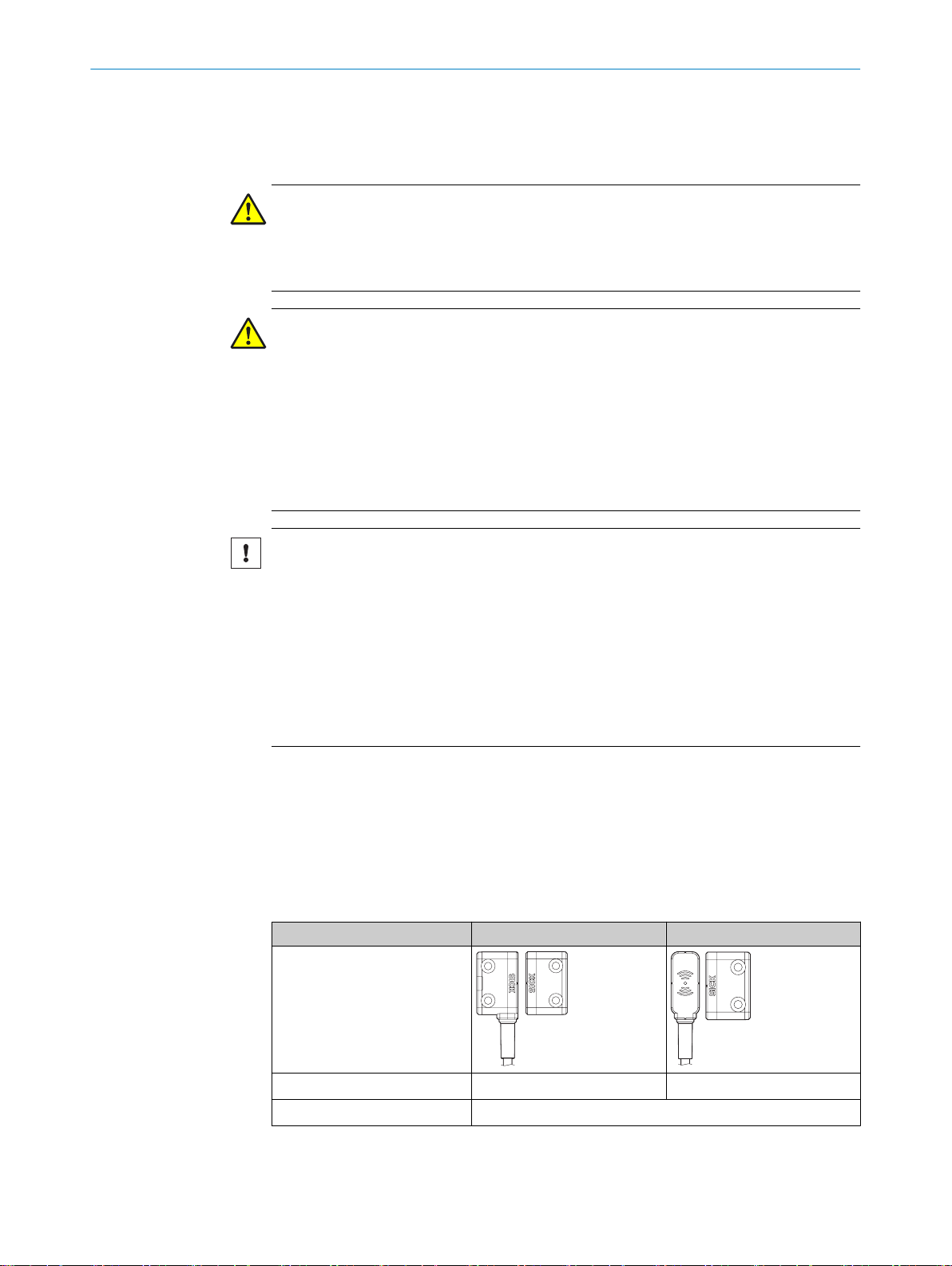
The safety switch consists of two components:
Sensor
•
The sensor is mounted on the fixed part of the protective device.
Actuator (transponder)
•
The actuator is mount
When the protective device is closed, the actuator is guided to the sensor. When the
switch on distance is reached, the sensor detects the actuator code. If the sensor
detects a taught-in code (valid actuator), it sets safety outputs OSSD 1 and OSSD 2
(semiconductor outputs) to High and application diagnostic output Aux to Low.
When the protective device is opened, the actuator is removed from the response range
of the sensor. The sensor sets safety outputs OSSD 1 and OSSD 2 to Low and applica‐
tion diagnostic output Aux to High.
3.2 Product characteristics
ed on the moving part of the protective device.
3.2.1 Product variants
The safety switch is delivered in different variants. You will find an overview of impor‐
t
ant distinguishing features of t
Universally coded, unique coded, and permanently coded safety switches
•
Actuator design: “Standard”, “Flat”, or “Mini”
•
Cable with M12 plug connector (5-pin or 8-pin) or flying leads (3 m or 10 m)
•
Complete overview of all variants: see "STR1 ordering information", page 40.
Coding
Universally coded
•
All actuator
Unique coded
•
An actuator must be taught in dur
taught in one after the o
Previously taught-in actuators can no longer be used.
Permanently coded
•
An actuator mus
performed once. It is not possible t
3.2.2 Active sensor surfaces
The sensor has 3 active sensor surfaces:
Front: black sur
•
2 x sides: yellow surface with long black edge
•
he variants in the following.
s are accepted. No teach-in is required.
ing commissioning. Up to 8 actuators may be
ther. Only the most recently taught-in actuator is valid.
t be taught in during commissioning. Teach-in only needs to be
o teach in any further actuators.
face
3.2.3 Fault detection
10
O PE R AT I NG IN S TR U CT I ON S | STR1 8018754/2016-xx-xx | SICK
Faults that arise, including internal device faults, are detected no later than the next
r
equirement to close t
switch then switches to the safe state. If a fault is detected, the safety circuit is
switched off and the DIAG and STATE light emitting diodes display the fault (see
table 10).
he safety contacts (e.g., when the machine starts). The safety
Subject to change without notice
Page 11

3.2.4 Cascading
Draft 2016-10-19
PRODUCT DESCRIPTION 3
In the case of cascading, up to 30 safety switches are connected in series.
F
or more information, see "Cascading",
page 25
3.2.5 State indicators
The STATE light emitting diode (red/green) and the DIAG light emitting diode (yellow)
signal t
Complete overview of the light emitting diode states and their meanings: see "Diagnos‐
tic LEDs", page 30.
3.2.6 Protective functions
The safety switch has the following internal protective functions:
•
•
•
•
page 16 and see "Connecting a cascade",
he operational state of the safety switch.
Short-circuit protection at all outputs
Cross-circuit monitoring at OSSDs
Overload protection at OSSDs
Reverse polarity protection for the supply voltage
8018754/2016-xx-xx | SICK OP E RA T IN G I N ST R UC T IO N S | STR1
Subject to change without notice
11
Page 12

4 PROJECT PLANNING
Draft 2016-10-19
4 Project planning
4.1 Manufacturer of the machine
DANGER
Failure to compl
Hazard due to lack of effectiveness of the protective device
Perform a risk assessment before using the safety switch.
b
Do not manipulate, open, or modify components of the safety switch.
b
Do not repair defective devices; replace them instead.
b
Make sure the switch-on commands that cause the machine to enter a dangerous
b
state only take effect when the protective device is closed.
Make sure a stop command is triggered when the protective device is opened in a
b
hazardous machine state.
Safety switches must not be bypassed (i.e., the contacts jumpered), swiveled out
b
of the way, removed, or rendered ineffective in any other way. If necessary, take
measures to reduce the possibility of bypassing.
If multiple devices are connected in series (cascaded) and the simplified procedure
according to ISO 13849 is used to det
drop.
y with manufacturer’s obligations
ermine the performance level (PL), the PL may
As the number of safety switches in a cascade increases, so too does the response
time.
4.2 Operating entity of the machine
DANGER
Failure to compl
Hazard due to lack of effectiveness of the protective device
Modifications to the machine and modifications to the mechanical mounting of
b
the safety switch necessitate a new risk assessment. The results of this risk
assessment may require the operating entity of the machine to fulfill the manufac‐
turer’s obligations.
Apart from during the procedures described in this document, the components of
b
the safety switch must not be opened or modified.
Do not perform repair work on the components. Improper repair of the safety
b
switch can lead to a loss of the protective function.
Make sure that bypassing is not carried out by substitute actuators. Restrict
b
access to actuators for unlocking.
y with operating entity’s obligations
12
O PE R AT I NG IN S TR U CT I ON S | STR1 8018754/2016-xx-xx | SICK
Subject to change without notice
Page 13

4.3 Design
Draft 2016-10-19
PROJECT PLANNING 4
DANGER
Bypassing the protectiv
Hazard due to lack of effectiveness of the protective device
Prevent incentives to manipulate the safety switch by taking at least one of the fol‐
b
lowing measures:
Universally coded variant only:
Co
°
°
Mounting location
ver the sensor and the actuat
against access.
If possible, use non-detachable mounting methods for actuators (such as
welding, gluing, safety screws, or rivets).
e device
or with additional equipment or protect them
When the protectiv
b
other at the safe switch on distance of Sao or closer (see table 3).
Select a mounting location that allows the sensor and actuator to be accessed for
b
maintenance work and protects them against damage.
If possible, mount the sensor and actuator on non-ferrous subsurfaces and at a
b
distance from metallic parts in order to avoid affecting the sensing range. If this is
not possible, the effect on the safe switch on distance Sao and the safe switch off
distance Sar must be checked.
Make sure that there is no possibility of hazards arising when the protective device
b
is opened, even if the actuator has not yet reached the safe switch off distance
Sar.
If the actuator is approaching the sensor in a parallel position, observe the mini‐
b
mum distances (see table 3).
If necessary, attach an additional stop for the moving protective device.
b
Distance
If multiple saf
minimum distance in relation to one another; see "Mounting", page 20.
Alignment
The sensor can be mounted in any alignment see "Mounting", page 20, see "Possible
mounting types", page 18.
ety switches are mounted on the machine, they must be mounted with a
e device is closed, the sensor and actuator must face each
4.4 Integration into the electrical control
8018754/2016-xx-xx | SICK OP E RA T IN G I N ST R UC T IO N S | STR1
Subject to change without notice
Actuating direction
The actuator may approach the front or the long side of the sensor.
NOTE
he actuat
If t
closed, but instead approaches it in a parallel position, the specified minimum distance
must be adhered to. This prevents the sensor from enabling the safety outputs despite
the protective device not being fully closed.
Switch-on commands that cause the machine to enter a dangerous state may only take
effect when the pro
ous state, a stop command must be triggered if the protective device opens. Depending
on the safety concept, the signal is analyzed by, e.g., safety relays or a safety controller.
or does no
t mo
e directly onto the sensor when the protective device is
v
tective device is closed. In cases where the machine is in a danger‐
13
Page 14
4 PROJECT PLANNING
Draft 2016-10-19
4.4.1 OSSDs
Safety switches with local inputs and outputs can be directly integrated into the
mac
hine controller.
DANGER
Hazard due to lack of effectiveness of the protective device
In the case of non-compliance, it is possible that the dangerous state of the machine
may not be stopped or not stopped in a timely manner.
Make sure that the following control and electrical requirements are met so the
b
protective function can be fulfilled.
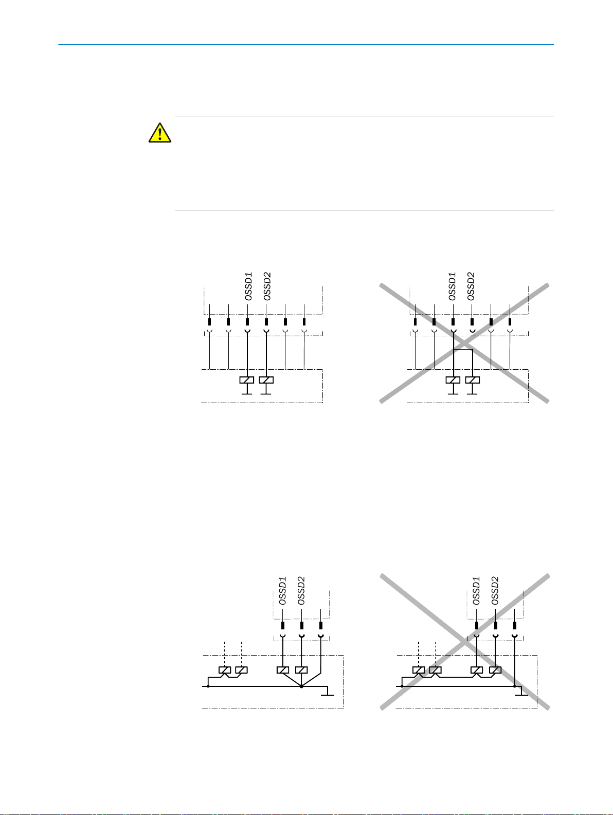
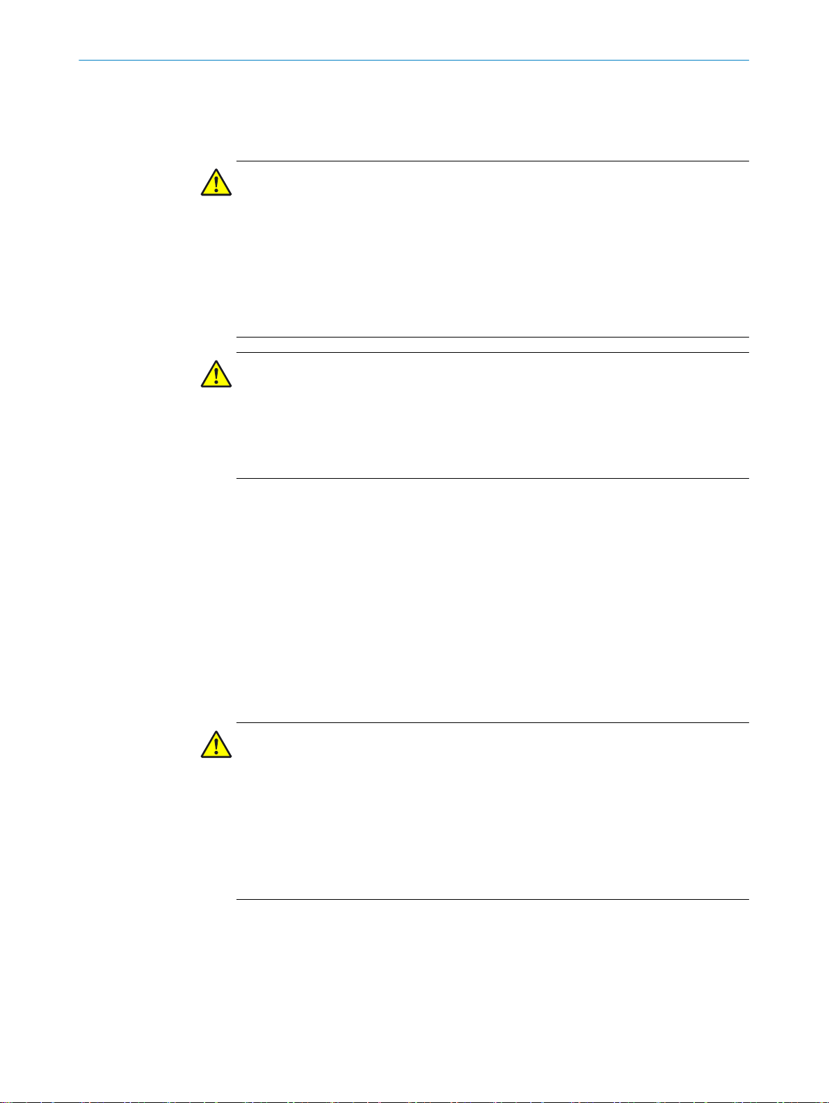
The output signals from an OSSD pair must not be connected to each other.
•
In the machine controller, both signals from an OSSD pair must be processed sep‐
•
arately.
Figure 1: Dual-channel and isolated connection of OSSD 1 and OSSD 2
The machine must switch to t
•
OSSD pair switches to the OFF state.
Prevent the formation of a potential difference between the load and the protec‐
•
tive device. If you connect loads to the OSSDs (safety outputs) that then also
switch if controlled with negative voltage (e.g., electro-mechanical contactor with‐
out reverse polarity protection diode), you must connect the 0 V connections of
these loads and those of the corresponding protective device individually and
directly to the same 0 V terminal strip. In the event of a fault, this is the only way to
ensure that there can be no potential difference between the 0 V connections of
the loads and those of the corresponding protective device.
he safe state at any time if at least one OSSD in an
14
O PE R AT I NG IN S TR U CT I ON S | STR1 8018754/2016-xx-xx | SICK
Figure 2: No potential difference between load and protective device
Subject to change without notice
Page 15
PROJECT PLANNING 4
Draft 2016-10-19
DANGER
Hazard due to lack of eff
In the case of non-compliance, it is possible that the dangerous state of the machine
may not be stopped or not stopped in a timely manner.
Downstream contactors must be positively guided and monitored depending on appli‐
cable national regulations or required reliability of the safety function.
Make sure that downstream contactors are monitored (external device monitoring,
b
EDM).
Requirements for the electrical control of the machine
ectiveness of the protective device
he contr
Use t
•
The safety switch tests the OSSDs at regular intervals. To do this, it switches each
•
OSSD briefly (for max. 1 ms) to the OFF state and checks whether this channel is
voltage-free during this time.
Make sure that the machine’s control does not react to these test pulses and the
machine does not switch off.
The in
•
The OSSDs are short-circuit protected to 24 V DC and 0 V. When the actuator is in the
sensor’s response range, the OSSDs signal the ON state with the HIGH signal level
(non-isolated). If the actuator is removed from the sensor’s response range or there is a
device fault, the OSSDs signal the OFF state with the LOW signal level.
The safety switch complies with the regulations for electromagnetic compatibility (EMC)
for the industrial sector (Radio Safety Class A). Radio interference cannot be ruled out
when used in residential areas.
DANGER
Hazar
In the case of non-compliance, it is possible that the dangerous state of the machine
may not be stopped or not stopped in a timely manner.
b
puts of a connect
two outputs of the safety switch send a level of the supply voltage in the switchedon state.
o lac
d due t
Make sure that the following control and electrical requirements are met so the
safety switch can fulfill its protective function.
hout t
ol wit
f
ectiveness of the protective device
k of ef
t pulses. The safety switch is self-testing.
es
ed evaluation unit mus
t be positive-switching (PNP), as the
4.4.2 Application diagnostic output
8018754/2016-xx-xx | SICK OP E RA T IN G I N ST R UC T IO N S | STR1
Subject to change without notice
The exter
•
power failures of 20 ms as specified in IEC 60204-1.
The power supply unit must provide safe isolation according to IEC 61140 (SELV/
•
PELV). Suitable power supply units are available as accessories from SICK.
The application diagnostic output signal changes as soon as the actuator is moved into
or leaves the response r
moving protective device is opened and closed. This is not a safety output.
Actuator Application diagnostic output
Actuator not in response range. ON
Actuator in response range. OFF
Table 1: Application diagnostic output switching behavior
nal v
olt
age supply of the safety switch must be capable of buffering brief
ange of the safety switch. In other words, it does so when the
15
Page 16
1 1 1 1 1 2
OSSD1
OSSD2
OSSD1
OSSD2
OSSD1
OSSD2
OSSD1
OSSD2
OSSD1
OSSD2
4 PROJECT PLANNING
Draft 2016-10-19
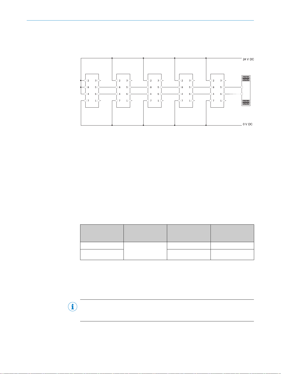
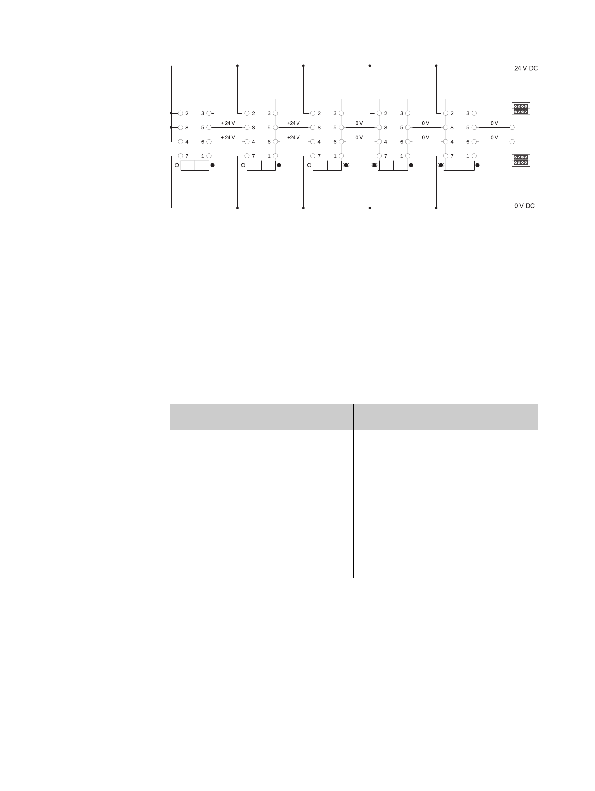
4.4.3 Cascading
Cascading makes it possible to connect multiple safety switches. The connected devi‐
ces act lik
e a single device. Cascading is only possible wit
h the variant that includes the
8-pin M12 male connector.
Figure 3: Circuit with 5 cascaded safety switches
Safety switch
Safe evaluation unit
It is not possible to use more than 30 safety switches in a cascade.
The maximum number of safety switches depends on the f
Applied supply voltage
•
Length of cables used
•
Cross-section of cables used
•
ollowing factors:
The voltage drop in the cascade must be checked to ensure that the defined minimum
voltage is still present at the last safety switch.
In the case of connection cables with a length of 2 m and a cable cross-section of
0.25 mm², the maximum number of cascadable safety switches is relative to the volt‐
age, as explained below:
Voltage Connection cables,
the same kind for the
entire cascade
24 V Length: 2 m
26.8 V 19.2 V 30
Table 2: Maximum number of cascadable safety switches relative to the voltage
Cable cross-section:
0.25 mm²
In
put voltage at 30th
safety switch
17.8 V 24
Maximum number of
cascadable safety
switches
The number of safety switches in a cascade affects the response time of the system
(see "Response time and enable time in cascade", page 39).
The cascade can be created using special T-pieces and an end connector (see "Con‐
necting a cascade", page 25).
NOTE
he case of safety switc
In t
16
O PE R AT I NG IN S TR U CT I ON S | STR1 8018754/2016-xx-xx | SICK
ate the application diagnostic output.
hes cascaded using T
-connectors, it is not possible to evalu‐
Subject to change without notice
Page 17

4.5 Thorough check concept
Draft 2016-10-19
Thorough checks must be performed on the safety switch by appropriately qualified
ety personnel during commissioning, af
saf
see "Thorough check", page 29
Regular thorough checks serve to investigate the effectiveness of the safety switch and
discover defects resulting from modifications or external influences (such as damage or
manipulation).
The manufacturer and operating entity must define the type and frequency of the thor‐
ough checks on the machine on the basis of the application conditions and the risk
assessment. The process of defining the thorough checks must be documented in a
traceable manner.
4.5.1 Minimum requirements for regular thorough checks
The following thorough checks must be carried out at least once a year:
PROJECT PLANNING 4
ter modifications, and at regular intervals.
Thorough check of the pr
•
Thorough check of the safe sensing range S
•
Thorough check for damage on the switch housing
•
Thorough check for damage on the switch cables
•
Thorough check for signs of misuse or manipulation on the safety switch
•
incipal protective function of the safety switch
ar
8018754/2016-xx-xx | SICK OP E RA T IN G I N ST R UC T IO N S | STR1
Subject to change without notice
17
Page 18
5 MOUNTING
Draft 2016-10-19
5 Mounting
5.1 Safety
DANGER
Hazard due to unexpected s
Death or severe injury
Make sure that the dangerous state of the machine is and remains switched off.
b
DANGER
Bypassing the protectiv
Hazard due to lack of effectiveness of the protective device
Prevent incentives to manipulate the safety switch by taking at least one of the fol‐
b
lowing measures:
Universally coded variant only: Attach safety switches with a cover or with
°
shielding, or ensure they are out of reach.
If possible, use non-detachable mounting methods for actuators (such as
°
welding, gluing, non-removable screws, or rivets).
tarting of the machine
e device
NOTICE
Incorrect mounting and unsuitable ambient conditions may damage the safety switch.
Arrange the sensor and actuator in a way that prevents damage from foreseeable
b
external influences.
Do not use the sensor and actuator as a stop.
b
The holder and mounting method for the sensor and actuator must be stable
b
enough to ensure that correct operation can take place.
Always use reliable mounting elements that can only be removed using tools.
b
If misalignment results in an opening on the physical guard, this must not impair
b
the protection that is provided.
5.2 Unpacking
Check the components for com
b
of delivery", page 40.
Please contact your respective SICK subsidiary should you have any complaints.
b
5.3 Possible mounting types
“Standard” actuator
pleteness and the integrity of all parts, see "Scope
Front actuation Side actuation
18
O PE R AT I NG IN S TR U CT I ON S | STR1 8018754/2016-xx-xx | SICK
Safe switch on distance S
Safe switch off distance S
Table 3: Safe switch-on range based on actuator, alignment, and approach direction
≤ 10 mm ≤ 6 mm
ao
≤ 25 mm
ar
Subject to change without notice
Page 19

Switch-on behavior with
–40
–20
2
0
40
0
0 4 8 12 16 20
[mm]
–40
–20
2
0
40
0
0 4 8 12 16 20
[mm]
–40
–20
20
40
0
0 4 8 12 16 20
[mm]
–40
–20
20
40
0
0 4 8 12 16 20
[mm]
Draft 2016-10-19
“Standard” actuator relativ
direction of approach
MOUNTING 5
Front actuation Side actuation
e to
“Flat” actuator
Safe switch on distance S
Safe switch off distance S
ao
ar
“Mini” actuator
Safe switch on distance S
Safe switch off distance S
ao
ar
Switch-on behavior with “Flat”
or “Mini” actuator relative to
dir
ection of approach
Peripheral zones with parallel
approach. Minimum distance:
6 mm
No peripheral zones. No mini‐
mum distance with parallel
oach
appr
≤ 14 mm ≤ 9 mm
≤ 28 mm
≤ 14 mm ≤ 9 mm
≤ 28 mm
8018754/2016-xx-xx | SICK OP E RA T IN G I N ST R UC T IO N S | STR1
Subject to change without notice
Peripheral zones with parallel
approach. Minimum distance:
10 mm
Peripheral zones with parallel
approach. Minimum distance:
4 mm
able 3: Safe switch-on range based on actuator, alignment, and approach direction
T
19
Page 20

5 MOUNTING
Draft 2016-10-19
5.4 Mounting
NOTE
If the actuator does not mov
closed, but instead approaches it in a parallel position, the specified minimum distance
must be adhered to. This prevents the sensor from enabling the safety outputs despite
the protective device not being fully closed.
Selecting the mounting location
e directly onto the sensor when the protective device is
he machine documentation does not specify t
If t
fully:
When the protective device is closed, the sensor and actuator must face each
b
other at the safe switch on distance of Sao or closer (see table 3).
Select a mounting location that allows the sensor and actuator to be accessed for
b
maintenance work and protects them against damage.
If possible, mount the sensor and actuator on non-ferrous subsurfaces and at a
b
distance from metallic parts in order to avoid affecting the sensing range. If this is
not possible, the effect on the safe switch on distance Sao and the safe switch off
distance Sar must be checked.
Make sure that there is no possibility of hazards arising when the protective device
b
is opened, even if the actuator has not yet reached the safe switch off distance
Sar.
If the actuator is approaching the sensor in a parallel position, observe the mini‐
b
mum distances (see table 3).
If necessary, attach an additional stop for the moving protective device.
b
Mounting the sensor
Mount the sensor on the fixed part of the protective device.
1.
2. Take account of the tightening torque for the fixing screws: 1 Nm
Mounting the actuator
1. Align the actuator using the marking notches on the sensor.
he mounting location, select one care‐
20
O PE R AT I NG IN S TR U CT I ON S | STR1 8018754/2016-xx-xx | SICK
Figure 4: Aligning the actuator on the sensor
2. If you are mounting using fixing screws, take account of the tightening torque for
the screws:
“Standard” and “Flat” actuators: 1 Nm
°
“Mini” actuator: 0.7 Nm
°
Subject to change without notice
Page 21

Mounting multiple safety switches
³ 140
³ 100
³ 100
³ 200
Draft 2016-10-19
MOUNTING 5
1. When mounting multiple safety switches, adher
e to the specified minimum dis‐
tance between the individual systems in order to avoid mutual interference.
8018754/2016-xx-xx | SICK OP E RA T IN G I N ST R UC T IO N S | STR1
Subject to change without notice
Figure 5: Minimum distances relative to the alignment of the safety switches
21
Page 22
6 ELECTRICAL INSTALLA
Draft 2016-10-19
TION
6 Electrical installation
6.1 Safety
DANGER
Hazard due to electrical volt
Hazard due to unexpected starting of the machine
Make sure that the machine is and remains disconnected from the power supply
b
during the electrical installation.
Make sure that the dangerous state of the machine is and remains switched off
b
during electrical installation.
Make sure that the outputs of the safety switch have no effect on the machine
b
during electrical installation.
DANGER
Incorrect safety switc
Loss of safety function
When using insulation material or stranded connection wires, make sure they
b
demonstrate the required temperature resistance and mechanical load capability.
Use only safe contacts for safety functions.
b
age
h connection
Use a suitable voltage suppl
b
PELV (IEC 60204-1) for all devices that are electrically connected to the safety
switch.
All devices that are electrically connected to the safety switch must have the same
b
voltage supply.
Use protected cable routing to eliminate cross-circuits and short-circuits.
b
Power devices (such as motors) that represent a strong source of interference
b
must be kept isolated from circuits for signal processing. Route the cables for the
safety circuits as far away as possible from the power circuit cables.
Make sure that 1 A fuse protection is provided for safety switches.
b
Make sure that all electrical outputs have an adequate suppressor to accommo‐
b
date inductive loads. For this purpose, the outputs must be protected with an
appropriate suppressor such as a freewheeling diode, a varistor, or an RC element.
DANGER
Hazard due to lack of effectiveness of the protective device
The dangerous state may not be stopped in the event of non-compliance.
Operate safety switches within the specifications. If you operate them outside the
b
specifications, this may result in the sensor temperature increasing and in a loss
of the safety function.
Make sure that a current of no more than 100 mA is flowing at safety outputs
b
OSSD 1 and OSSD 2. Otherwise, it is no longer possible to guarantee the safety
function.
y. Voltage must be supplied in accordance with SELV/
22
O PE R AT I NG IN S TR U CT I ON S | STR1 8018754/2016-xx-xx | SICK
Subject to change without notice
Page 23
ELECTRICAL INSTALLATION 6
Draft 2016-10-19
DANGER
Hazard due to lack of eff
The dangerous state may not be stopped in the event of non-compliance.
Always connect the two OSSDs separately. The two OSSDs must not be connected
b
to each other.
Connect the OSSDs such that the machine controller processes both signals sepa‐
b
rately.
ectiveness of the protective device
DANGER
Hazard due to lack of eff
The dangerous state may not be stopped in the event of non-compliance.
Prevent the formation of a potential difference between the load and the protec‐
b
tive device.
If you connect loads to the OSSDs (safe
b
led with negative voltage (e.g., electro-mechanical contactor without reverse polar‐
ity protection diode), you must connect the 0 V connections of these loads and
those of the corresponding protective device individually and directly to the same
0 V terminal strip. In the event of a fault, this is the only way to ensure that there
can be no potential difference between the 0 V connections of the loads and
those of the corresponding protective device.
ectiveness of the protective device
ty outputs) that then also switch if control‐
6.2 Notes on cULus
8018754/2016-xx-xx | SICK OP E RA T IN G I N ST R UC T IO N S | STR1
Subject to change without notice
The following conditions must also be fulfilled in order to use and apply the equipment
in accordance with UL 508 requirements:
23
Page 24

12
3 4
5
3
4
8
5
6
1
7
2
6 ELECTRICAL INSTALLATION
Draft 2016-10-19
The voltage supply mus
•
Connections In 1 and In 2 must conform to Class 2 according to UL 508.
•
The device must have 1 A fuse protection.
•
6.3 Device connection (flying leads)
Wire color Designation Description
Brown +24 V DC 24 V DC voltage supply
White OSSD 1 Output OSSD 1
Blue 0 V 0 V DC voltage supply
Black OSSD 2 Output OSSD 2
Gray Aux Application diagnostic output
Table 4: Device connection cable assignment
6.4 Device connection (M12, 5-pin)
t conform to Class 2 according to UL 508.
(not safe)
Figure 6: Device connection (male connector, M12, 5-pin, A-coded)
Pin Wire color
1 Brown +24 V DC 24 V DC voltage supply
2 White OSSD 1 Output OSSD 1
3 Blue 0 V 0 V DC voltage supply
4 Black OSSD 2 Output OSSD 2
5 Gray Aux Application diagnostic output
Table 5: Device connection pin assignment (male connector, M12, 5-pin, A-coded)
1)
Applies to the extension cables recommended as accessories.
e t
Ensur
b
1)
he plug connect
6.5 Device connection (M12, 8-pin)
Figure 7: Device connection (male connector, M12, 8-pin, A-coded)
Designation Description
(not safe)
or is tightl
y connect
ed.
24
O PE R AT I NG IN S TR U CT I ON S | STR1 8018754/2016-xx-xx | SICK
Pin Wire color
1 White Aux Application diagnostic output
2 Bro
Table 6: Device connection pin assignment (male connector, M12, 8-pin, A-coded)
1)
wn +24 V DC 24 V DC voltage supply
Designation Description
(not safe)
Subject to change without notice
Page 25
ELECTRICAL INSTALLATION 6
Draft 2016-10-19
Pin Wire color
3 Green N.C. Not connected
4 Yellow In 2 Input OSSD 2
5 Gray OSSD 1 Output OSSD 1
6 Pink OSSD 2 Output OSSD 2
7 Blue 0 V 0 V DC voltage supply
8 Red In 1 Input OSSD 1
Table 6: Device connection pin assignment (male connector, M12, 8-pin, A-coded)
1)
Applies to the extension cables recommended as accessories.
2)
When used as a single safety switch or as the first safety switch in a cascade: apply 24 V DC (see "Con‐
necting a cascade", page 25).
Ensure the plug connector is tightly connect
b
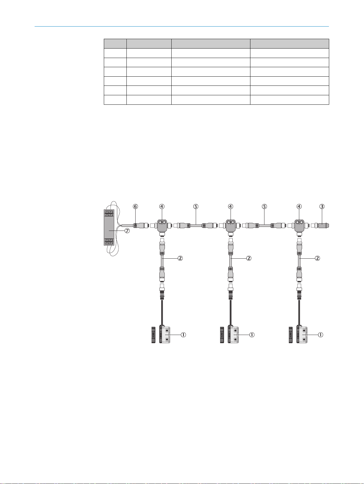
6.6 Connecting a cascade
Structure of a cascade
The cascade can be created using special T-connector
"Accessories", page 43).
1)
Designation Description
2)
2)
ed.
s and an end connector (see
8018754/2016-xx-xx | SICK OP E RA T IN G I N ST R UC T IO N S | STR1
Subject to change without notice
Figure 8: Cascading multiple safety switches
STR1 safety switch
M12 connection cable, 8-pin
End connector
T-piece
M12 connection cable, 4-pin
M12 connecting cable, 4-pin
Safe evaluation unit
25
Page 26

5
4
3
2
1
55
44
33
2
2
1
1
5
6 7
8
4
3
21
12
3 4
5
6 ELECTRICAL INSTALLATION
Draft 2016-10-19
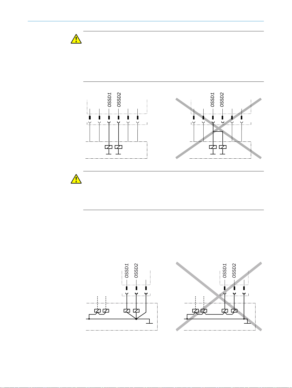
Figure 9: Internal circuitry: end connector for cascade
Figure 10: Internal circuitry: T-piece for cascade
DANGER
Bypassing the protectiv
e device
The dangerous state may not be stopped in the event of non-compliance.
If the cascade is created using T-pieces, install the connecting cables in a way that pre‐
vents a single T-piece (and therefore a safety switch) from simply being jumpered.
NOTE
In the case of safety switches cascaded using T
-connectors, it is not possible to evalu‐
ate the application diagnostic output.
NOTE
If special T-pieces and end connectors are no
t being used to create the cascade, make
sure that inputs In 1 and In 2 are connected to a constant 24 V DC at the first safety
switch in the cascade.
Cascade connection (M12, 5-pin)
The 5-pin male connect
or of t
he las
t T
-piece bef
ore the safe evaluation unit is the inter‐
face between the cascade and the safe evaluation unit.
26
O PE R AT I NG IN S TR U CT I ON S | STR1 8018754/2016-xx-xx | SICK
Figure 11: Cascade connection (M12, 5-pin, A-coded, male connector)
Subject to change without notice
Page 27

ELECTRICAL INSTALLATION 6
Draft 2016-10-19
Pin Wire color
1)
Designation Description
1 Brown +24 V DC 24 V DC voltage supply
2 White OSSD 1 Output OSSD 1
3 Blue 0 V 0 V DC voltage supply
4 Black OSSD 2 Output OSSD 2
5 Gray N.C. Not connected
Table 7: Cascade connection pin assignment (male connector, M12, 5-pin, A-coded)
1)
Applies to the extension cables recommended as accessories.
8018754/2016-xx-xx | SICK OP E RA T IN G I N ST R UC T IO N S | STR1
Subject to change without notice
27
Page 28

7 COMMISSIONING
Draft 2016-10-19
7 Commissioning
7.1 Safety
DANGER
Hazard due to lack of eff
In the case of non-compliance, it is possible that the dangerous state of the machine
may not be stopped or not stopped in a timely manner.
1. Have qualified safety personnel perform a thorough check on the machine and
approve it before commissioning.
2. Make sure that the time for the safety requirement (closing the protective device
again) is longer than the risk time.
7.2 Switching on
The device initializes after switching on. During this process, the OSSDs are switched
off and the light emitting diodes light up alternately in the color sequence green, red,
and yellow. For unique coded and permanently coded safety switches only: If any actua‐
tors have already been taught in, the STATE light emitting diode will flash once after ini‐
tialization for each taught-in actuator.
ectiveness of the protective device
7.3 Teach-in
DANGER
Bypassing the protectiv
The dangerous state may not be stopped in the event of non-compliance.
If an actuator is taught in, document this
b
During regular thorough checks, make sure that the taught-in actuator is still being
b
used.
Variant for universally coded actuators
No teach-in is req
Variant for unique coded actuators
An actuator must be taught in during commissioning. Up to 8 actuators may be taught
in one after the other. Only the most recently taught-in actuator is valid. Previously
taught-in actuators cannot be taught in again.
Variant for permanently coded actuators
An actuator must be taught in during commissioning. It is not possible to teach in any
further actuators.
Teaching in an actuator
e device
uired.
28
O PE R AT I NG IN S TR U CT I ON S | STR1 8018754/2016-xx-xx | SICK
1. Open the physical guard.
2. Connect the safety switch to the voltage supply (see "Electrical installation",
page 22).
✓
The start sequence is performed. The LEDs light up alternately in the color
sequence green, red, and yellow.
3. Close the physical guard.
✓
When the guard is closed and the actuator has reached the appropriate position,
the safety switch will automatically start the teach-in sequence. The LEDs will dis‐
Subject to change without notice
Page 29

4. Within 5 minutes of successfully teaching in the actuator, connect and restore the
Draft 2016-10-19
✓
NOTE
Actuators can only be taught in at cascaded safety switches if voltage is present at
inputs In 1 and In 2. For this purpose, the actuators must be taught in individually in a
specific order. Viewed from the evaluation unit, teach-in starts at the last safety switch
in the cascade (STATE light emitting diode lights up red, DIAG light emitting diode is off).
Then the actuator is taught in at the second-to-last safety switch in the cascade, and so
on.
7.4 Thorough check
COMMISSIONING 7
play the individual steps.
STATE light emitting
diode (red/green)
green yellow
green yellow
Table 8: Displays for teach-in sequences
voltage supply f
Once the taught-in actuator is in the response range, both OSSDs switch to the ON
state and the STATE light emitting diode lights up green.
DIAG light emitting
diode (y
or the safety switch.
ellow)
Step
A
ctuator is being taught in
A
ctuator has been taught in
Requirements for the thorough check during commissioning and in certain situations
The protective de
situations:
Before commissioning
•
After changes to the configuration or the safety function
•
After changes to the mounting, the alignment, or the electrical connection
•
After exceptional events, such as after a manipulation has been detected, after
•
modification of the machine, or after replacing components
The thorough check ensures the following:
Compliance with all relevant regulations and effectiveness of the protective device
•
for all of the machine’s operating modes.
The documentation corresponds to the state of the machine, including the protec‐
•
tive device
The thorough checks must be carried out by qualified safety personnel or specially
qualified and authorized personnel and must be documented in a traceable manner.
1. Check whether the protective device of the machine is effective in all operating
modes in whic
Make sure that the operating personnel have been instructed in the function of
2.
the protective device before starting work on the machine. The instruction is the
responsibility of the machine operator and must be carried out by qualified per‐
sonnel.
vice and its application must be thoroughly checked in the following
h t
he mac
hine can be se
t.
8018754/2016-xx-xx | SICK OP E RA T IN G I N ST R UC T IO N S | STR1
Subject to change without notice
29
Page 30

8 TR
Draft 2016-10-19
OUBLESHOOTING
8 Troubleshooting
8.1 Safety
DANGER
Hazard due to lack of eff
In the case of non-compliance, it is possible that the dangerous state of the machine
may not be stopped or not stopped in a timely manner.
Immediately put the machine out of operation if the behavior of the machine can‐
b
not be clearly identified.
Immediately put the machine out of operation if you cannot clearly identify or allo‐
b
cate the fault and if you cannot safely remedy the fault.
Secure the machine such that it cannot be switched on unintentionally.
b
DANGER
Hazard due to unexpected s
When any work is taking place, use the protective device to secure the machine or
b
to ensure that the machine is not switched on unintentionally.
ectiveness of the protective device
tarting of the machine
DANGER
Hazard due to lack of eff
In the case of non-compliance, it is possible that the dangerous state of the machine
may not be stopped or not stopped in a timely manner.
b
b
b
NOTE
If you cannot remedy the f
please contact your respective SICK subsidiary.
8.2 Diagnostic LEDs
8.2.1 Switching on
STATE light emitting diode
(red/green)
green
red
yellow
green
T
able 9: LED displays dur
1)
For unique coded and permanently coded safety switches only: If any actuators have already been taught
in, t
ectiveness of the protective device
Do not carry out any repairs on the device components.
Do not make any modifications to or manipulate the device components.
Apart from during the procedures described in this document, the device compo‐
nents must not be opened.
ault with the help of the information provided in this chapter,
el‐
Duration
500 ms
500 ms
500 ms
1)
TE light emitting diode will f
he STA
DIAG light emitting diode (y
low)
ing initialization
lash once after initialization for each taught-in actuator.
30
O PE R AT I NG IN S TR U CT I ON S | STR1 8018754/2016-xx-xx | SICK
Subject to change without notice
Page 31

8.2.2 State display
Draft 2016-10-19
8.2.3 Fault displays
STATE light emitting diode
(red/green)
red
green
ed yellow
r
DIAG light emitting diode (y
low)
TROUBLESHOOTING 8
el‐
Meaning
No voltage supply
No valid actuator in r
range. OSSD pair in OFF stat
Actuator in response r
OSSD pair in ON state
Signal at OSSD in
In 2 invalid or not present.
OSSD pair in OFF s
puts In 1 and
tate
esponse
e
ange.
STATE light emitting
diode (red/green)
red yellow
r
ed
Table 10: Fault displays
DIAG light emitting
diode (y
ellow)
Possible cause Corrective measure
No voltage supply Check voltage supply.
If the light emitting
diodes do not light up
oltage sup‐
k OSSD 1
Chec
and OSSD 2 for
short-circuit
do
wnstream of
0 V or 24 V DC,
or between one
another
Check cabling
for damage.
There must be a
dual-channel
configuration.
he faulty
e t
Isolat
sensor and
chec
k it sepa‐
rately
Check wiring for
cross-circuits
and short-cir‐
cuits.
Switch the volt‐
age supply off
and on.
If the fault still
occurs after this,
the sensor is
defective.
Replace sensor.
Ext
ernal fault
Internal fault
even if a v
ply is present, replace
the safety switch.
•
•
•
•
•
•
8.2.4 Fault displays in cascading
8018754/2016-xx-xx | SICK OP E RA T IN G I N ST R UC T IO N S | STR1
Subject to change without notice
If a fault affects a device in a cascade, the device in question displays the fault and
switc
hes off the OSSDs (ST
ATE light emitting diode flashes red). All downstream devices
switch off their OSSDs (STATE light emitting diode lights up red, DIAG light emitting
diode flashes yellow).
31
Page 32
1
DIAGSTATE
2 3 4 5
DIAGSTATE
DIAG
STATE
DIAGSTATE
DIAG
STATE
6
6 7
8 8
!
8 TROUBLESHOOTING
Draft 2016-10-19
Figure 12: Fault displays on cascaded safety switches. The example shows an internal fault at
safety switch 3
Safety switch
–
Light emitting diode lights up green
Light emitting diode flashes red
Light emitting diode lights up red
What to do in the event of a fault affecting cascaded safety switches:
e the faulty sensor and chec
Isolat
•
Check wiring for cross-circuits and short-circuits.
•
Switch the voltage supply off and on. If the fault still occurs after this, the sensor is
•
defective. Replace sensor.
8.2.5 Fault displays during teach-in
STATE light emitting
ed/green)
diode (r
red/green yellow
red/green yellow
red/green
Table 11: Fault displays during teach-in
Fault displays are repeated until the equipment is reset.
S
ATE light emitting
T
diode (yellow)
k it separately.
Cause
The maximum number of actuat
taught in. It is not possible to carr
teach-in process.
An actuat
needs to be taught in again. This is not possi‐
ble.
Teach-in sequence f
again. Possible fault:
•
•
or that has already been taught in
ailed. Teach in the actuator
ctuator removed from response range
A
too early.
Voltage supply not isolated in a timely
manner.
ors has been
y out another
32
O PE R AT I NG IN S TR U CT I ON S | STR1 8018754/2016-xx-xx | SICK
To perform a r
b
eset, disconnect the voltage supply for at least 3 s.
Subject to change without notice
Page 33

9 Maintenance
Draft 2016-10-19
9.1 Cleaning
NOTICE
Do not use aggressive cleaning ag
b
Do not use any substances that hinder the wetting properties of lacquers.
b
We recommend anti-static cleaning agents.
b
9.2 Regular thorough check
The safety switch must be thoroughly checked regularly. The type and frequency of thor‐
ough checks are def
see "Thorough check concept", page 17
Regular thorough checks serve to investigate the effectiveness of the safety switch and
detect any ineffectiveness due to modifications or external influences (such as damage
or manipulation).
1. Carry out the thorough checks according to the instructions from the manufacturer
and the operating entity of the machine.
MAINTEN
ents.
ined by the manufacturer and the operating entity of the machine;
ANCE 9
8018754/2016-xx-xx | SICK OP E RA T IN G I N ST R UC T IO N S | STR1
Subject to change without notice
33
Page 34

10 DECOMMISSIONING
Draft 2016-10-19
10 Decommissioning
10.1 Protection of the environment
The safety switch has been designed to minimize its impact on the environment. It uses
a minimum of energy and resources.
ys act in an environmentally responsible manner at work. For this reason,
Alwa
b
please note the following information regarding disposal.
10.2 Disposal
Always dispose of serviceableness devices in compliance with local/national rules and
egulations with respect to w
r
NOTE
We would be pleased to be of assistance on the disposal of this device. Contact us.
aste disposal.
34
O PE R AT I NG IN S TR U CT I ON S | STR1 8018754/2016-xx-xx | SICK
Subject to change without notice
Page 35

11 Technical data
Draft 2016-10-19
11.1 Technical data
Features
e switch on distance Sao (IEC 60947 5-3)
Saf
Front actuation
Side actuation
Typical switch on distance
Front actuation
Side actuation
Safe switch off distance S
Max. actuation frequency 0.5 Hz
Cascading ≤ 30 safety switches
Table 12: Features
TECHNICAL DATA 11
“Standard”
actuator
10 mm
6 mm
14 mm
8 mm
ar
25 mm 28 mm 28 mm
“Flat” actuator “Mini” actua‐
tor
14 mm
9 mm
19 mm
12 mm
14 mm
9 mm
19 mm
12 mm
Safety-related parameters
Performance level PL e (EN ISO 13849-1)
Category 4 (EN ISO 13849)
Safety integrity level SIL 3 (EN 61508)
SIL claim limit SILCL 3 (EN 62061)
PFHd (mean probability of a dangerous failure
per hour)
5.21 × 10⁻⁹ at 40 °C and mean sea level
14 x 10–9 at 40 °C and 2,000 m
TM (mission time) 20 years (EN ISO 13849-1)
R
esponse time (removal from response range) ≤ 40 ms
Enable time (reaction time when approaching
esponse range)
r
Risk time
Lengt
Minimum distance be
1)2)
h of cable
3)
tween 2 safety switches Dependent on alignment see "Mounting",
≤ 100 ms
≤ 80 ms
≤ 200 m
page 20
Type Type 4 (EN ISO 14119)
Coding level
Universally coded
Unique coded
Permanentl
y coded
Low coding level (EN ISO 14119)
High coding le
vel (EN ISO 14119)
High coding level (EN ISO 14119)
Safe state when a fault occurs At least one OSSD is in the OFF state
Table 13: Safety-related parameters
1)
At least one of the two OSSD outputs is safely switched off within the reaction time.
2)
The risk time is the fault detection time in the case of internal or external faults. External faults affect the
OSSDs (shor
is safely switched off within the risk time.
3)
The length of cable and the cable cross-section change the voltage drop according to the output current
(R
max
t-circuit to an OSSD or cross-cir
= 14.5 Ω).
cuit between the two OSSDs). At least one of the two OSSDs
8018754/2016-xx-xx | SICK OP E RA T IN G I N ST R UC T IO N S | STR1
Subject to change without notice
35
Page 36

11 TECHNICAL DATA
Draft 2016-10-19
Interfaces
System connection
Voltage supply
Local inputs and outputs
Male connector, M12, 5-pin, A-coded (common
male connect
or
Male connector, M12, 8 pin, A-coded (common
male connector for voltage supply and inputs
and outputs) or
Flying leads
Length of connecting cable 3 m or 10 m
Table 14: Interfaces
Electrical data
OSSD pairs 1
Rated impulse withstand voltage U
imp
Pollution degree 3 (ext
1,500 V
ernal, according to EN 60947-1)
Power-up delay (after supply voltage is applied)1)2.5 s
or for voltage supply and outputs)
Supply voltage V
s
24 V DC (19.2 V ... 28.8 V)
Rated insulation voltage Ui 32 V DC
Cable capacitance 400 nF (for Out A and Out B)
or Out A
vice fuse pr
De
tection 1 A
o
2 μF (f
ux)
Current consumption (without load) 50 mA
Protection class III (EN 61140/IEC 61140)
Table 15: Electrical data
1)
Once the supply voltage is switched on, the OSSDs and the application diagnostic output will be in the
OFF state during t
0.1 s is added for each sensor. In the case of unique coded and permanently coded sensors, an addi‐
tional 0.5 s must be added per taught-in actuator.
he time delay before availability. The specified time applies to one sensor; in a cascade,
Mechanical data
Dimensions (W x H x D)
Safety switch
“Standard” actuator
“Flat” actuator
“Mini” actuat
or
40 mm x 18 mm x 26 mm
figure 15
see
see figure 16
see figure 17
Material
®
al
Sensor
ctuator
A
Vist
V
istal
®
Weight
Safety switch
“Standard” actuator
“Flat” actuator
“Mini” actuat
or
63 g ... 436 g (depending on variant)
26 g
13 g
6 g
Table 16: Mechanical data
36
O PE R AT I NG IN S TR U CT I ON S | STR1 8018754/2016-xx-xx | SICK
Inputs
Rated voltage 24 V DC (19,2 V ... 28,8 V)
Table 17: Inputs
Subject to change without notice
Page 37

TECHNICAL DATA 11
Draft 2016-10-19
Inputs
Switching current
ON state
OFF state
Switching v
ON state
OFF state
Table 17: In
Outputs
2 OSSDs (Out 1 and Out 2) 2 x PNP, 100 mA max., short-circuit protected
Application diagnos
Switching current
ON state
OFF state
Switching v
ON state
OFF state
Table 18: Outputs
oltage
puts
tic output (Aux) 50 mA max., short-circuit protected
oltage
≤ 5 mA
0 mA
21 V DC ... 24 V DC
≤ 2 V DC
and overload-proof
≤ 100 mA
< 500 µA
21 V DC ... 24 V DC
0 V DC ... 2 V DC
Ambient data
Enclosure rating IP 67 (IEC 60529)
Ambient operating temperature –10 °C … +70 °C
Storage temperature –25 °C … +70 °C
Vibration resistance 1 mm/10 Hz ... 55 Hz (IEC 60068-2-6)
Shock resistance 30 g, 11 ms (IEC 60068-2-27)
EMC According to IEC/EN 61326-3-1, IEC/
EN 60947-5-2, and IEC/EN 60947-5-3
Table 19: Ambient data
8018754/2016-xx-xx | SICK OP E RA T IN G I N ST R UC T IO N S | STR1
Subject to change without notice
37
Page 38

18
14
M12 x 1
13,5
Ø 5,5
19
26,2
40
25175
3
5
Ø 8,5
22
18
14 13,5
Ø 5,5
19
26,2
40
25L
3
5
Ø 8,5
22
18
Ø 4,5
19
22
26,2
5
Ø 8,5
11 TECHNICAL DATA
Draft 2016-10-19
11.2 Dimensional drawings
Sensor
Figure 13: Dimensional drawing for STR1 sensor
with M12 male connector
Actuat
or
Figure 14: Dimensional drawing for STR1 sensor
with flying leads
Figure 15: STR1 dimensional drawing, “Standard” actuator
38
O PE R AT I NG IN S TR U CT I ON S | STR1 8018754/2016-xx-xx | SICK
Subject to change without notice
Page 39

18 9
24
Ø 4,5
Ø 8,51
5
Figure 16: STR1 dimensional drawing, “Flat” actuator
9 7
23
Ø 3,4
Ø 6,5
4
Draft 2016-10-19
TECHNICAL DATA 11
Figure 17: STR1 dimensional drawing, “Mini” actuator
11.3 Response time and enable time in cascade
The reaction times are subject to the following parameters:
esponse time or enable time
R
•
Number of cascaded devices
•
Response time (r
Response time for cascade: 40 ms + 80 ms * number of safety switc
Enable time (actuator approaching response range)
Enable time for cascade: 100 ms + 80 ms * number of safety switches in cascade
emoval of actuator from response range)
hes in cascade
8018754/2016-xx-xx | SICK OP E RA T IN G I N ST R UC T IO N S | STR1
Subject to change without notice
39
Page 40

12 ORDERING INFORMATION
Draft 2016-10-19
12 Ordering information
12.1 Scope of delivery
Sensor
•
Actuator
•
Safety no
•
Operating instructions for download: www.sick.com
•
12.2 STR1 ordering information
Actuator Sensor connection type Type code Part number
Flat Cable with male connector,
Standard Cable with male connector,
Mini Cable with male connector,
Table 20: STR1 ordering information, universally coded
te
STR1-SAFM0AC5 1069565
M12, 5-pin
Cable with male connector,
M12, 8-pin
Cable, 5-wire, 3 m STR1-SAFM03P5 1069567
Cable, 5-wire, 10 m STR1-SAFM10P5 1069568
M12, 5-pin
Cable with male connector,
M12, 8-pin
Cable, 5-wire, 3 m STR1-SASM03P5 1069562
Cable, 5-wire, 10 m STR1-SASM10P5 1069563
M12, 5-pin
Cable with male connector,
M12, 8-pin
Cable, 5-wire, 3 m STR1-SAMM03P5 1069572
Cable, 5-wire, 10 m STR1-SAMM10P5 1069573
STR1-SAFM0AC8 1069566
STR1-SASM0AC5 1069560
STR1-SASM0AC8 1069561
STR1-SAMM0AC5 1069570
STR1-SAMM0AC8 1069571
40
O PE R AT I NG IN S TR U CT I ON S | STR1 8018754/2016-xx-xx | SICK
Actuator Sensor connection type Type code Part number
Flat Cable with male connector,
M12, 5-pin
Cable with male connector,
M12, 8-pin
Cable, 5-wire, 3 m STR1-SAFU03P5 1069577
Cable, 5-wire, 10 m STR1-SAFU10P5 1072707
Standard Cable with male connector,
M12, 5-pin
Cable with male connector,
M12, 8-pin
Cable, 5-wire, 3 m STR1-SASU03P5 1072711
Cable, 5-wire, 10 m STR1-SASU10P5 1072712
Table 21: STR1 ordering information, unique coded
STR1-SAFU0AC5 1069575
STR1-SAFU0AC8 1069576
STR1-SASU0AC5 1072709
STR1-SASU0AC8 1072710
Subject to change without notice
Page 41

ORDERING INFORMATION 12
Draft 2016-10-19
Actuator Sensor connection type Type code Part number
Mini Cable with male connector,
M12, 5-pin
Cable with male connector,
M12, 8-pin
Cable, 5-wire, 3 m STR1-SAMU03P5 1073201
Cable, 5-wire, 10 m STR1-SAMU10P5 1073203
Table 21: STR1 ordering information, unique coded
Actuator Sensor connection type Type code Part number
Flat Cable with male connector,
M12, 5-pin
Cable with male connector,
M12, 8-pin
Cable, 5-wire, 3 m STR1-SAFF03P5 1073208
Cable, 5-wire, 10 m STR1-SAFF10P5 1073209
Standard Cable with male connector,
M12, 5-pin
Cable with male connector,
M12, 8-pin
Cable, 5-wire, 3 m STR1-SASF03P5 1073213
Cable, 5-wire, 10 m STR1-SASF10P5 1073214
Mini Cable with male connector,
M12, 5-pin
Cable with male connector,
M12, 8-pin
Cable, 5-wire, 3 m STR1-SAMF03P5 1073218
Cable, 5-wire, 10 m STR1-SAMF10P5 1073219
Table 22: STR1 ordering information, permanently coded
STR1-SAMU0AC5 1073205
STR1-SAMU0AC8 1073204
STR1-SAFF0AC5 1073206
STR1-SAFF0AC8 1073207
STR1-SASF0AC5 1073211
STR1-SASF0AC8 1073212
STR1-SAMF0AC5 1073216
STR1-SAMF0AC8 1073217
8018754/2016-xx-xx | SICK OP E RA T IN G I N ST R UC T IO N S | STR1
Subject to change without notice
41
Page 42

13 SPARE PARTS
Draft 2016-10-19
13 Spare parts
13.1 Actuator
Type Type code Part number
Flat STR1-XAF 1073221
Standard STR1-XAS 1073223
Mini STR1-XAM 1073222
Table 23: Actuator
13.2 Sensors
Coding Connection type Type code Part number
Universally coded Cable with male connector,
Unique coded Cable with male connector,
Permanently
coded
Table 24: Sensors
STR1-XDAM0AC5 1073224
M12, 5-pin
Cable with male connector,
M12, 8-pin
Cable, 5-wire, 3 m STR1-XDAM03P5 1073226
Cable, 5-wire, 10 m STR1-XDAM10P5 1073227
M12, 5-pin
Cable with male connector,
M12, 8-pin
Cable, 5-wire, 3 m STR1-XDAU03P5 1073231
Cable, 5-wire, 10 m STR1-XDAU10P5 1073232
Cable with male connector,
M12, 5-pin
Cable with male connector,
M12, 8-pin
Cable, 5-wire, 3 m STR1-XDAF03P5 1073235
Cable, 5-wire, 10 m STR1-XDAF10P5 1073236
STR1-XDAM0AC8 1073225
STR1-XDAU0AC5 1073228
STR1-XDAU0AC8 1073230
STR1-XDAF0AC5 1073233
STR1-XDAF0AC8 1073234
42
O PE R AT I NG IN S TR U CT I ON S | STR1 8018754/2016-xx-xx | SICK
Subject to change without notice
Page 43

14 Accessories
Draft 2016-10-19
14.1 Connectivity
Connecting cable, M12, 4-pin (0.34 mm2)
Part Type code Part number
Female connector straight, 5 m cable, open
end
Female connector straight, 10 m cable, open
end
Female connector straight, 15 m cable, open
end
Female connector straight, 20 m cable, open
end
Table 25: Ordering information for M12 connecting cable, 4-pin (0.34 mm2)
Connecting cable, M12, 5-pin (0.34 mm2)
Part Type code Part number
Female connector straight, 2 m cable, open
end
Female connector straight, 5 m cable, open
end
Female connector straight, 10 m cable, open
end
Table 26: Ordering information for M12 connecting cable, 5-pin (0.34 mm2)
ACCESSORIES 14
DOL-1204-G05MC 6025901
DOL-1204-G10MC 6025902
DOL-1204-G15MC 6034749
DOL-1204-G20MC 6034750
)
1
DOL-1205-G02MC 6025906
DOL-1205-G05MC 6025907
DOL-1205-G10MC 6025908
1)
Connection cable, M12, 8-pin (0.25 mm2)
Part Type code Part number
Female connector straight, 5 m cable, open
DOL-1208-G05MA 6020993
end
Female connector straight, 10 m cable, open
DOL-1208-G10MA 6022152
end
Female connector straight, 15 m cable, open
DOL-1208-G15MA 6022153
end
Female connector straight, 30 m cable, open
DOL-1208-G30MA 6022242
end
Table 27: Ordering information for M12 connecting cable, 8-pin (0.25 mm2)
1)
Connection cable, M12, 4-pin (0.25 mm2)
Part Type code Part number
Female connector straight, 0.6 m cable, male
connector straight
emale connector straight, 2 m cable, male
F
connector straight
emale connector straight, 5 m cable, male
F
connector straight
Table 28: Ordering information for M12 connection cable, 4-pin (0.25 mm2)
DSL-1204-G0M6 6022565
DSL-1204-G02M 6022567
DSL-1204-G05M 6022569
1)
1)
Ambient operating temperatur
8018754/2016-xx-xx | SICK OP E RA T IN G I N ST R UC T IO N S | STR1
Subject to change without notice
Connection cable, M12, 4-pin (0.34 mm2)
e: down to -30 °C with fixed installation.
43
Page 44

14 ACCESSORIES
Draft 2016-10-19
Part Type code Part number
Female connector straight, 0.6 m cable, male
DSL-1204-G1M5 6034822
connector straight
F
emale connector straight, 10 m cable, male
DSL-1204-G10M 6034406
connector straight
Female connector straight, 20 m cable, male
DSL-1204-G20M 6034407
connector straight
Table 29: Ordering information for M12 connection cable, 4-pin (0.34 mm2)
1)
Connection cable, M12, 8-pin (0.25 mm2)
Part Type code Part number
Female connector straight, 1 m cable, male
connector straight
Female connector straight, 2 m cable, male
connector straight
Female connector straight, 5 m cable, male
connector straight
Female connector straight, 10 m cable, male
connector straight
Table 30: Ordering information for M12 connection cable, 8-pin (0.25 mm2)
DSL-1208-G01MAC 6026625
DSL-1208-G02MAC 6030121
DSL-1208-G05MA
C 6032325
DSL-1208-G10MAC 6034901
1)
Distributor
Part Type code Part number
T-piece TR4-AK004C 5325889
Table 31: Ordering information for distributor
End connector
Part Type code Part number
End connector for series connection TR4-AL002C 5325890
Table 32: Ordering information for end connector
1)
Ambient operating temperatur
44
O PE R AT I NG IN S TR U CT I ON S | STR1 8018754/2016-xx-xx | SICK
e: down to -30 °C with fixed installation.
Subject to change without notice
Page 45

15 Annex
Draft 2016-10-19
15.1 Compliance with EU directives
EU declaration of conformity (excerpt)
ANNEX 15
The undersigned, representing the f
product is in conformity with the provisions of the following EU directive(s) (including all
applicable amendments), and that the respective standards and/or technical specifica‐
tions are taken as the basis.
Complete EU declaration of conformity for download
You can call up the EU declaration of conformity and the current operating instructions
for the protective device by entering the part number in the search field at
www.sick.com (part number: see the type label entry in the “Ident. no.” field).
ollowing manufacturer herewith declares that the
8018754/2016-xx-xx | SICK OP E RA T IN G I N ST R UC T IO N S | STR1
Subject to change without notice
45
Page 46

15 ANNEX
Draft 2016-10-19
15.2 FCC and IC radio approval
FCC ID: 2AHDRSTR1
•
IC: 21147STR1
•
The device fulfills t
with the following extracts from the relevant approvals:
FCC § 15.19
he EMC requirements for use in the USA and Canada, in accordance
This device complies with Par
two conditions:
This device may not cause harmful interference, and
•
this device must accept any interference received, including interference that may
•
cause undesired operation.
FCC §15.21 (warning statement)
y] changes or modifications no
[An
pliance could void the user’s authority to operate the equipment.
IC
This device complies with Industry Canada’s licence-exempt RSSs. Operation is subject
to the following two conditions:
This device may not cause interference; and
•
This device must accept any interference, including interference that may cause
•
undesired operation of the device.
Le présent appareil est conforme aux CNR d’Industrie Canada applicables aux appa‐
reils radio exempts de licence. L’exploitation est autorisée aux deux conditions sui‐
vantes :
l’appareil ne doit pas produire de brouillage;
•
l’utilisateur de l’appareil doit accepter tout brouillage radioélectrique subi, même
•
si le brouillage est susceptible d’en compromettre le fonctionnement.
t 15 of the FCC rules. Operation is subject to the following
t expressly approved by the party responsible for com‐
46
O PE R AT I NG IN S TR U CT I ON S | STR1 8018754/2016-xx-xx | SICK
Subject to change without notice
Page 47

16 List of figures
Draft 2016-10-19
1. Dual-channel and isolated connection of OSSD 1 and OSSD 2..............................14
2. No potential difference between load and protective device.................................. 14
3. Circuit with 5 cascaded safety switches................................................................... 16
4. Aligning the actuator on the sensor.......................................................................... 20
5. Minimum distances relative to the alignment of the safety switches.....................21
6. Device connection (male connector, M12, 5-pin, A-coded).....................................24
7. Device connection (male connector, M12, 8-pin, A-coded).....................................24
8. Cascading multiple safety switches.......................................................................... 25
9. Internal circuitry: end connector for cascade........................................................... 26
10. Internal circuitry: T-piece for cascade....................................................................... 26
11. Cascade connection (M12, 5-pin, A-coded, male connector)................................. 26
12. Fault displays on cascaded safety switches. The example shows an internal fault
13. Dimensional dr
14. Dimensional drawing for STR1 sensor with flying leads.......................................... 38
15. STR1 dimensional drawing, “Standard” actuator.....................................................38
16. STR1 dimensional drawing, “Flat” actuator..............................................................39
17. STR1 dimensional drawing, “Mini” actuator.............................................................39
LIST OF FIGURES 16
at safety switch 3........................................................................................................32
awing for STR1 sensor with M12 male connector.......................... 38
8018754/2016-xx-xx | SICK OP E RA T IN G I N ST R UC T IO N S | STR1
Subject to change without notice
47
Page 48

17 LIST OF TABLES
Draft 2016-10-19
17 List of tables
1. Application diagnostic output switching behavior....................................................15
2. Maximum number of cascadable safety switches relative to the voltage.............. 16
3. Safe switch-on range based on actuator, alignment, and approach direction.......18
4. Device connection cable assignment........................................................................24
5. Device connection pin assignment (male connector, M12, 5-pin, A-coded).......... 24
6. Device connection pin assignment (male connector, M12, 8-pin, A-coded).......... 24
7. Cascade connection pin assignment (male connector, M12, 5-pin, A-coded).......27
8. Displays for teach-in sequences................................................................................29
9. LED displays during initialization...............................................................................30
10. Fault displays.............................................................................................................. 31
11. Fault displays during teach-in.................................................................................... 32
12. Features...................................................................................................................... 35
13. Safety-related parameters......................................................................................... 35
14. Interfaces.................................................................................................................... 36
15. Electrical data............................................................................................................. 36
16. Mechanical data......................................................................................................... 36
17. Inputs...........................................................................................................................36
18. Outputs........................................................................................................................37
19. Ambient data.............................................................................................................. 37
20. STR1 ordering information, universally coded..........................................................40
21. STR1 ordering information, unique coded................................................................40
22. STR1 ordering information, permanently coded...................................................... 41
23. Actuator.......................................................................................................................42
24. Sensors....................................................................................................................... 42
25. Ordering information for M12 connecting cable, 4-pin (0.34 mm2) ...................... 43
26. Ordering inf
27. Ordering information for M12 connecting cable, 8-pin (0.25 mm2) ...................... 43
28. Ordering information for M12 connection cable, 4-pin (0.25 mm2) ...................... 43
29. Ordering information for M12 connection cable, 4-pin (0.34 mm2) ...................... 44
30. Ordering information for M12 connection cable, 8-pin (0.25 mm2) ...................... 44
31. Ordering information for distributor...........................................................................44
32. Ordering information for end connector....................................................................44
ormation for M12 connecting cable, 5-pin (0.34 mm2) ...................... 43
48
O PE R AT I NG IN S TR U CT I ON S | STR1 8018754/2016-xx-xx | SICK
Subject to change without notice
Page 49

LIST OF TABLES 17
Draft 2016-10-19
8018754/2016-xx-xx | SICK OP E RA T IN G I N ST R UC T IO N S | STR1
Subject to change without notice
49
Page 50

17 LIST OF TABLES
Draft 2016-10-19
50
O PE R AT I NG IN S TR U CT I ON S | STR1 8018754/2016-xx-xx | SICK
Subject to change without notice
Page 51

LIST OF TABLES 17
Draft 2016-10-19
8018754/2016-xx-xx | SICK OP E RA T IN G I N ST R UC T IO N S | STR1
Subject to change without notice
51
Page 52

Australia
Phone +61 3 9457 0600
1800 334 802 – tollfree
E-Mail sales@sick.com.au
Austria
Phone +43 22 36 62 28 8-0
E-Mail office@sick.at
Belgium/Luxembourg
Phone +32 2 466 55 66
E-Mail info@sick.be
Brazil
Phone +55 11 3215-4900
E-Mail marketing@sick.com.br
Canada
Phone +1 905 771 14 44
E-Mail information@sick.com
Czech Republic
Phone +420 2 57 91 18 50
E-Mail sick@sick.cz
Chile
Phone +56 2 2274 7430
E-Mail info@schadler.com
China
Phone +86 20 2882 3600
E-Mail info.china@sick.net.cn
Denmark
Phone +45 45 82 64 00
E-Mail sick@sick.dk
Finland
Phone +358-9-2515 800
E-Mail sick@sick.fi
France
Phone +33 1 64 62 35 00
E-Mail info@sick.fr
Germany
Phone +49 211 5301-301
E-Mail info@sick.de
Hong Kong
Phone +852 2153 6300
E-Mail ghk@sick.com.hk
Hungary
Phone +36 1 371 2680
E-Mail office@sick.hu
India
Phone +91 22 4033 8333
E-Mail info@sick-india.com
Israel
Phone +972 4 6881000
E-Mail info@sick-sensors.com
Italy
Phone +39 02 274341
E-Mail info@sick.it
Japan
Phone +81 3 5309 2112
E-Mail support@sick.jp
Malaysia
Phone +6 03 8080 7425
E-Mail enquiry.my@sick.com
Mexico
Phone +52 472 748 9451
E-Mail mario.garcia@sick.com
Netherlands
Phone +31 30 2044 000
E-Mail info@sick.nl
New Zealand
Phone +64 9 415 0459
0800 222 278 – tollfree
E-Mail sales@sick.co.nz
Norway
Phone +47 67 81 50 00
E-Mail sick@sick.no
Poland
Phone +48 22 539 41 00
E-Mail info@sick.pl
Romania
Phone +40 356 171 120
E-Mail office@sick.ro
Russia
Phone +7 495 775 05 30
E-Mail info@sick.ru
Singapore
Phone +65 6744 3732
E-Mail sales.gsg@sick.com
Slovakia
Phone +421 482 901201
E-Mail mail@sick-sk.sk
Slovenia
Phone +386 591 788 49
E-Mail office@sick.si
South Africa
Phone +27 11 472 3733
E-Mail info@sickautomation.co.za
South Korea
Phone +82 2 786 6321
E-Mail info@sickkorea.net
Spain
Phone +34 93 480 31 00
E-Mail info@sick.es
Sweden
Phone +46 10 110 10 00
E-Mail info@sick.se
Switzerland
Phone +41 41 619 29 39
E-Mail contact@sick.ch
Taiwan
Phone +886 2 2375-6288
E-Mail sales@sick.com.tw
Thailand
Phone +66 2645 0009
E-Mail Ronnie.Lim@sick.com
Turkey
Phone +90 216 528 50 00
E-Mail info@sick.com.tr
United Arab Emirates
Phone +971 4 88 65 878
E-Mail info@sick.ae
United Kingdom
Phone +44 1727 831121
E-Mail info@sick.co.uk
USA
Phone +1 800 325 7425
E-Mail info@sick.com
Vietnam
Phone +84 945452999
E-Mail Ngo.Duy.Linh@sick.com
Further locations at www.sick.com
8018754/2016-xx-xx/en
Draft 2016-10-19
SICK AG | Waldkirch | Germany | www.sick.com
 Loading...