

Page 1

SIM2000ST
Sensor Integration Machine
O P E R A T I N G I N S T R U C T I O N S
Page 2

Described product
SIM2000ST
Manufacturer
SICK AG
Erwin-Sick-Str. 1
79183 Waldkirch
Germany
Legal information
This work is protected by copyright. Any rights derived from the copyright shall be
reserved for SICK AG. Reproduction of this document or parts of this document is only
permissible within the limits of the legal determination of Copyright Law. Any modifica‐
tion, abridgment or translation of this document is prohibited without the express writ‐
ten permission of SICK AG.
The trademarks stated in this document are the property of their respective owner.
© SICK AG. All rights reserved.
Original document
This document is an original document of SICK AG.
2
O PE R AT I NG IN S TR U CT I ON S | SIM2000ST 8020764/ZM92/2017-08-04 | SICK
Subject to change without notice
Page 3

Contents
CONTENTS
1 About this document........................................................................ 5
1.1 Information on the operating instructions.............................................. 5
1.2 Explanation of symbols............................................................................ 5
1.3 Further information................................................................................... 6
1.4 Customer service...................................................................................... 6
2 Safety information............................................................................ 7
2.1 General safety notes................................................................................ 7
2.2 Intended use............................................................................................. 7
2.3 Improper use............................................................................................. 7
2.4 IP technology............................................................................................. 8
2.5 Limitation of liability................................................................................. 8
2.6 Modifications and conversions................................................................ 8
2.7 Requirements for skilled persons and operating personnel.................. 9
2.8 Operational safety and particular hazards.............................................. 9
3 Product description........................................................................... 11
3.1 Device view................................................................................................ 11
3.2 Functionality.............................................................................................. 11
3.3 SICK AppSpace......................................................................................... 13
3.4 Preset ETHERNET interfaces................................................................... 13
4 Transport and storage....................................................................... 14
4.1 Transport................................................................................................... 14
4.2 Transport inspection................................................................................. 14
4.3 Storage...................................................................................................... 14
5 Mounting............................................................................................. 15
5.1 Overview of mounting procedure............................................................. 15
5.2 Scope of delivery....................................................................................... 15
5.3 Preparing for mounting............................................................................. 15
5.4 Mounting the device................................................................................. 16
5.5 Mounting the device (at a critical ambient temperature of max.
50 °C)........................................................................................................ 18
6 Electrical installation........................................................................ 20
6.1 Important information.............................................................................. 20
6.2 Preparing the electrical installation......................................................... 20
6.3 Assembling the cables (optional)............................................................ 20
6.4 Pin allocation of the connections............................................................ 21
6.5 Connecting peripheral devices................................................................ 25
6.6 Connecting voltage supply....................................................................... 26
7 Commissioning.................................................................................. 27
7.1 Preparatory commissioning..................................................................... 27
8020764/ZM92/2017-08-04 | SICK OP E RA T IN G I N ST R UC T IO N S | SIM2000ST
Subject to change without notice
3
Page 4

CONTENTS
8 Operation............................................................................................ 28
8.1 Status LEDs............................................................................................... 28
9 Maintenance...................................................................................... 31
9.1 Cleaning..................................................................................................... 31
9.2 Maintenance............................................................................................. 31
10 Decommissioning............................................................................. 32
10.1 Disposal..................................................................................................... 32
11 Technical data.................................................................................... 33
11.1 Features.................................................................................................... 33
11.2 Interfaces.................................................................................................. 33
11.3 Mechanics and electronics...................................................................... 34
11.4 Ambient data............................................................................................. 35
12 Annex.................................................................................................. 36
12.1 Dimensional drawings.............................................................................. 36
12.2 Licenses.................................................................................................... 37
4
O PE R AT I NG IN S TR U CT I ON S | SIM2000ST 8020764/ZM92/2017-08-04 | SICK
Subject to change without notice
Page 5
1 About this document
1.1 Information on the operating instructions
These operating instructions provide important information on how to use devices from
SICK AG.
Prerequisites for safe work are:
Compliance with all safety notes and handling instructions supplied.
•
Compliance with local work safety regulations and general safety regulations for
•
device applications
The operating instructions are intended to be used by qualified personnel and electrical
specialists.
NOTE
Read these operating instructions carefully before starting any work on the device, in
order to familiarize yourself with the device and its functions.
The instructions constitute an integral part of the product and are to be stored in the
immediate vicinity of the device so they remain accessible to staff at all times. Should
the device be passed on to a third party, these operating instructions should be handed
over with it.
ABOUT THIS DOCUMENT 1
These operating instructions do not provide information on operating the machine or
system in which the device is integrated. For information about this, refer to the operat‐
ing instructions of the specific machine.
1.2 Explanation of symbols
Warnings and important information in this document are labeled with symbols. The
warnings are introduced by signal words that indicate the extent of the danger. These
warnings must be observed at all times and care must be taken to avoid accidents, per‐
sonal injury, and material damage.
DANGER
… indicates a situation of imminent danger, which will lead to a fatality or serious inju‐
ries if not prevented.
WARNING
… indicates a potentially dangerous situation, which may lead to a fatality or serious
injuries if not prevented.
CAUTION
… indicates a potentially dangerous situation, which may lead to minor/slight injuries if
not prevented.
NOTICE
… indicates a potentially harmful situation, which may lead to material damage if not
prevented.
NOTE
… highlights useful tips and recommendations as well as information for efficient and
trouble-free operation.
8020764/ZM92/2017-08-04 | SICK OP E RA T IN G I N ST R UC T IO N S | SIM2000ST
Subject to change without notice
5
Page 6

1 ABOUT THIS DOCUMENT
1.3 Further information
NOTE
All the documentation available for the device can be found on the online product page
at:
www.sick.com/SIM2000
b
The following information is available for download there:
Model-specific online data sheets for device variants, containing technical data,
•
dimensional drawings and diagrams
EU declaration of conformity for the product family
•
Dimensional drawings and 3D CAD dimension models in various electronic for‐
•
mats
These operating instructions, available in English and German, and in other lan‐
•
guages if necessary
Other publications related to the devices described here
•
Publications dealing with accessories
•
1.4 Customer service
If you require any technical information, our customer service department will be happy
to help. To find your representative, see the final page of this document.
NOTE
Before calling, make a note of all type label data such as type code, serial number, etc.,
to ensure faster processing.
6
O PE R AT I NG IN S TR U CT I ON S | SIM2000ST 8020764/ZM92/2017-08-04 | SICK
Subject to change without notice
Page 7

2 Safety information
2.1 General safety notes
The following safety notes must always be observed regardless of specific application
conditions:
The device must only be mounted, commissioned, operated, and maintained by
•
professionally qualified safety personnel.
Electrical connections with peripheral devices must only be made when the volt‐
•
age supply is disconnected.
The device is only to be operated when mounted in a fixed position.
•
The device voltage supply must be protected in accordance with the specifications.
•
The specified ambient conditions must be observed at all times.
•
The electrical connections to peripheral devices must be screwed on or clamped
•
correctly.
The cooling fins must not be covered or restricted in their functionality.
•
The pin assignment of pre-assembled cables must be checked and adjusted if
•
necessary.
These operating instructions must be made available to the operating personnel
•
and kept ready to hand.
SAFETY INFORMATION 2
2.2 Intended use
The device is a programmable control and evaluation unit for sensors and image proc‐
essing devices. The device also acts as a link between system and plant controls, and
the connected terminal devices. The device is mainly used in an industrial environment
in production, testing, and control. Other applications are possible depending on the
device-specific properties.
The device is programmed on a PC by using the development environment software
SICK AppSpace. Depending on the application, a browser-based, graphical user inter‐
face (HMI) can be created, which provides opportunities defined by the application
developer to influence an application at operator level.
The device connection to the peripherals is established by means of a range of indus‐
trial fieldbuses and other interfaces.
The device offers various interfaces for controlling, programming, and operating pur‐
poses, which can be activated as necessary via development environments, control sys‐
tems (programmable logic controllers), or applications.
However, configuration, programming, and control requires various technical skills,
depending on how the device is connected and used.
2.3 Improper use
Any use outside of the stated areas, in particular use outside of the technical specifica‐
tions and the requirements for intended use, will be deemed to be incorrect use.
The device does not constitute a safety-relevant device according to the EC Machi‐
•
nery Directive (2006/42/EC).
The device must not be used in explosion-hazardous areas, in corrosive environ‐
•
ments or under extreme environmental conditions.
Any use of accessories not specifically approved by SICK AG is at your own risk.
•
8020764/ZM92/2017-08-04 | SICK OP E RA T IN G I N ST R UC T IO N S | SIM2000ST
Subject to change without notice
7
Page 8
2 SAFETY INFORMATION
WARNING
Danger due to improper use!
Any improper use can result in dangerous situations.
Therefore, observe the following information:
■
■
2.4 IP technology
NOTE
SICK uses standard IP technology in its products. The emphasis is placed on availability
of products and services.
SICK always assumes the following prerequisites:
•
•
Device should be used only in accordance with its intended use.
All information in these operating instructions must be strictly observed.
The customer ensures the integrity and confidentiality of the data and rights
affected by its own use of the aforementioned products.
In all cases, the customer implements the appropriate security measures, such as
network separation, firewalls, virus protection, and patch management.
2.5 Limitation of liability
Applicable standards and regulations, the latest state of technological development,
and our many years of knowledge and experience have all been taken into account
when assembling the data and information contained in these operating instructions.
The manufacturer accepts no liability for damage caused by:
■
Failing to observe the operating instructions
■
Incorrect use
■
Use by untrained personnel
■
Unauthorized conversions
■
Technical modifications
■
Use of unauthorized spare parts, consumables, and accessories
With special variants, where optional extras have been ordered, or owing to the latest
technical changes, the actual scope of delivery may vary from the features and illustra‐
tions shown here.
2.5.1 Programmable device
The Sensor Integration Machine (SIM) is a programmable device.
Therefore the respective programmer is responsible for his/her programming perform‐
ance and the resulting working principle of the device.
The liability and warranty of SICK AG is limited to the device specification (hardware
functionality and any programming interfaces) according to the agreed conditions.
2.6
8
Therefore, SICK AG is not liable, among other things, for damages that are caused by
programming of the customer or third parties.
Modifications and conversions
NOTICE
Modifications and conversions to the device may result in unforeseeable dangers.
O PE R AT I NG IN S TR U CT I ON S | SIM2000ST 8020764/ZM92/2017-08-04 | SICK
Subject to change without notice
Page 9
Interrupting or modifying the device or SICK software will invalidate any warranty claims
against SICK AG. This applies in particular to opening the housing, even as part of
mounting and electrical installation.
2.7 Requirements for skilled persons and operating personnel
WARNING
Risk of injury due to insufficient training.
Improper handling of the device may result in considerable personal injury and material
damage.
■
All work must only ever be carried out by the stipulated persons.
The operating instructions state the following qualification requirements for the various
areas of work:
■
Instructed personnel have been briefed by the operator about the tasks assigned
to them and about potential dangers arising from improper action.
■
Skilled personnel have the specialist training, skills, and experience, as well as
knowledge of the relevant regulations, to be able to perform tasks delegated to
them and to detect and avoid any potential dangers independently.
■
Electricians have the specialist training, skills, and experience, as well as knowl‐
edge of the relevant standards and provisions to be able to carry out work on elec‐
trical systems and to detect and avoid any potential dangers independently. In Ger‐
many, electricians must meet the specifications of the BGV A3 Work Safety Regu‐
lations (e.g. Master Electrician). Other relevant regulations applicable in other
countries must be observed.
SAFETY INFORMATION 2
The following qualifications are required for various activities:
Table 1: Activities and technical requirements
Activities Qualification
Mounting, maintenance
Electrical installation,
device replacement
Basic practical technical training
■
Knowledge of the current safety regulations in the workplace
■
Practical electrical training
■
Knowledge of current electrical safety regulations
■
Knowledge of the operation and control of the devices in
■
their particular application
Commissioning, configura‐
tion
Basic knowledge of the WindowsTM operating system in use
■
Basic knowledge of the design and setup of the described
■
connections and interfaces
Basic knowledge of data transmission
■
Operation of the device for
the particular application
Knowledge of the operation and control of the devices in
■
their particular application
Knowledge of the software and hardware environment for
■
the particular application
2.8 Operational safety and particular hazards
Please observe the safety notes and the warnings listed here and in other chapters of
these operating instructions to reduce the possibility of risks to health and avoid dan‐
gerous situations.
8020764/ZM92/2017-08-04 | SICK OP E RA T IN G I N ST R UC T IO N S | SIM2000ST
Subject to change without notice
9
Page 10
2 SAFETY INFORMATION
WARNING
Electrical voltage!
Electrical voltage can cause severe injury or death.
b
b
b
b
b
WARNING
Dangerous equipotential bonding currents!
Improper grounding can lead to dangerous equipotential bonding currents, which may
in turn lead to dangerous voltages on metallic surfaces, such as the housing. Electrical
voltage can cause severe injury or death.
b
b
b
Work on electrical systems must only be performed by qualified electricians.
The power supply must be disconnected when attaching and detaching electrical
connections.
The sensor must only be connected to a voltage source as set out in the require‐
ments in the operating instructions.
National and regional regulations must be complied with.
Safety requirements relating to work on electrical systems must be complied with.
Work on electrical systems must only be performed by qualified electricians.
Follow the notes in the operating instructions.
Install the grounding for the sensor and the system in accordance with national
and regional regulations.
2.8.1 LED RG0
The product is fitted with LEDs in risk group 0. The accessible radiation from these
LEDs does not pose a danger to the eyes or skin.
10
O PE R AT I NG IN S TR U CT I ON S | SIM2000ST 8020764/ZM92/2017-08-04 | SICK
Subject to change without notice
Page 11
3 Product description
1
2 3 4 5 6 7 89ß
à á â
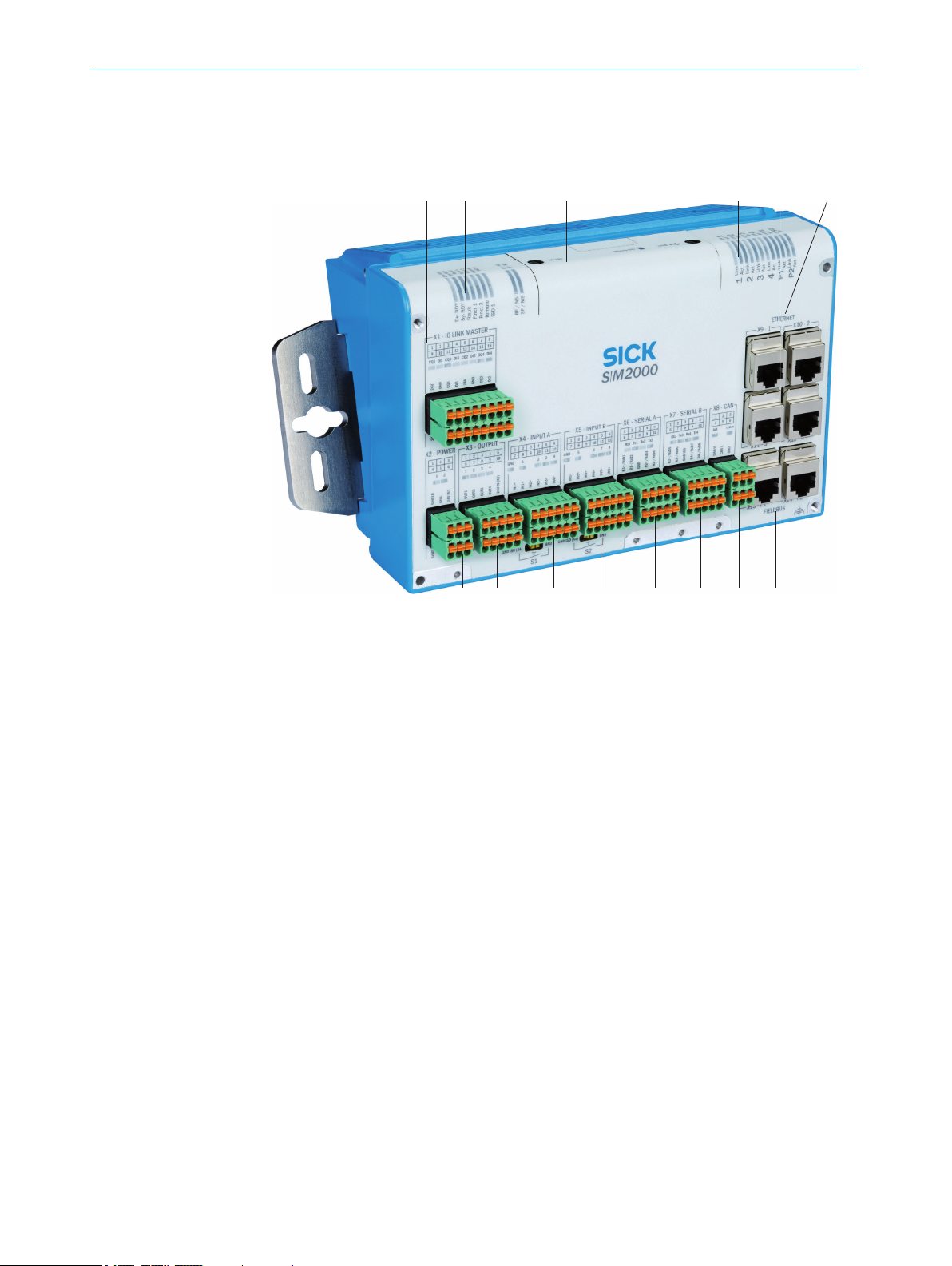
3.1 Device view
PRODUCT DESCRIPTION 3
1
2
3
4
5
6
7
8
9
ß
à
á
â
3.2 Functionality
The Sensor Integration Machine – part of the SICK AppSpace eco-system – is opening
up new possibilities for customized application solutions.
Data from SICK sensors such as 1D/2D code sensors and VMS4xx/5xx for detecting
object geometry can be imported, evaluated, archived, and transmitted. In order to do
this, the sensors can be connected to the SIM via the CAN bus. Ethernet-based fieldbus
interfaces ensure rapid communication with controls.
X1 – IO LINK MASTER: connections for IO-Link and/or GPIO
X2 – POWER: connections for the device voltage supply
X3 – OUTPUT: connections for digital switching outputs
X4 – INPUT A: connections for digital switching inputs A
X5 – INPUT B: connections for digital switching inputs B
X6 – SERIAL A: serial connections A
X7 – SERIAL B: serial connections B
X8 – CAN: connections for SICK CAN sensor network with termination resistor which can
be activated
X9 to X12 – ETHERNET: 4 Ethernet connections
X13 to X14 – FIELDBUS: 2 connections for Ethernet-based fieldbuses
Device status indicators
Servicing panel: function button, function selector switch, USB connection (for configura‐
tion/diagnostics)
Status indicators for Ethernet and fieldbus connections
8020764/ZM92/2017-08-04 | SICK OP E RA T IN G I N ST R UC T IO N S | SIM2000ST
Subject to change without notice
11
Page 12
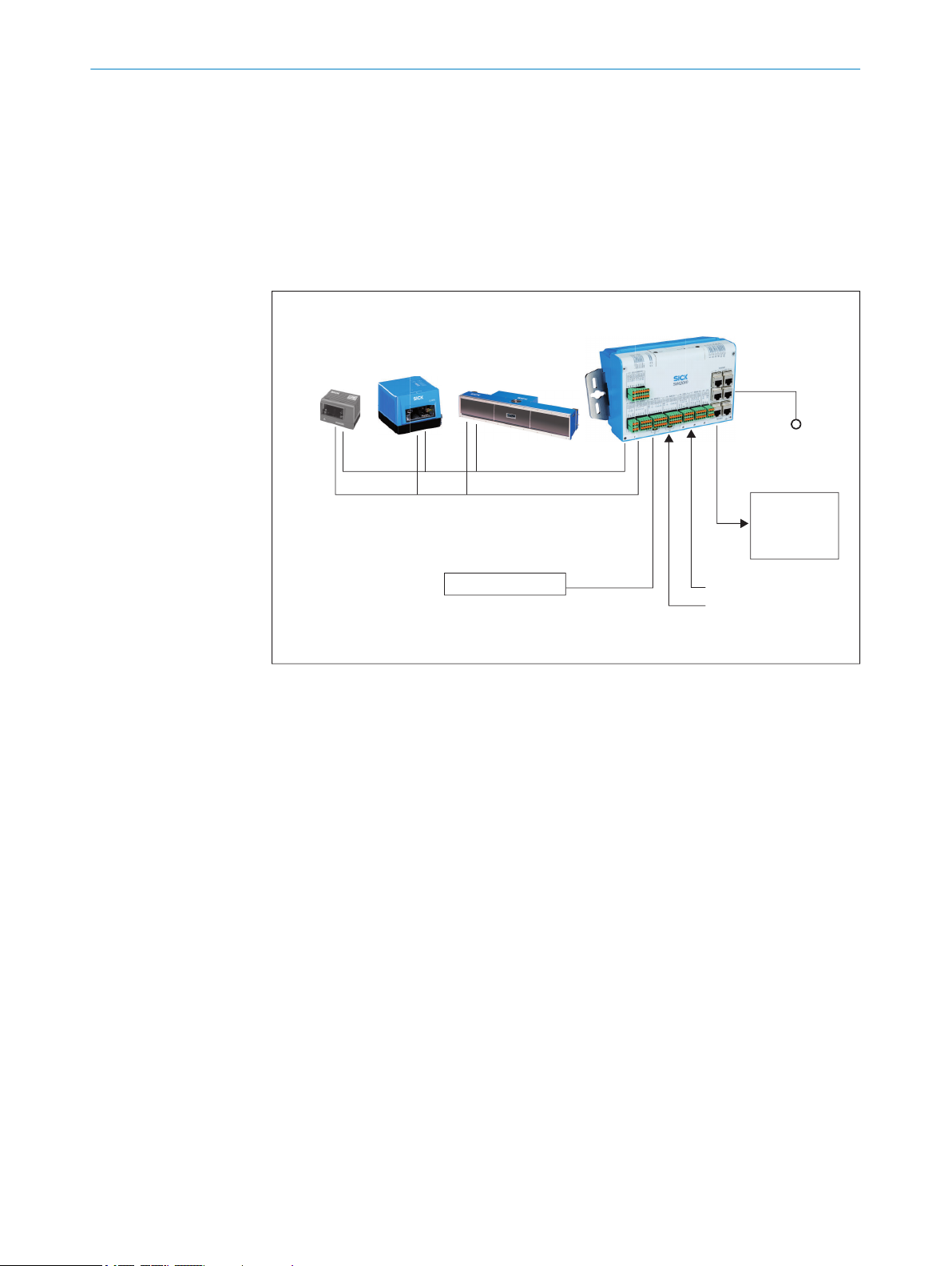
SIM2000ST
Supply voltage
Power supply
connection
ICR890 system
CAN bus
HOST
Read cycle
Conveyor speed
MLG light grid
Object distance
(optional)
VMS4xx/5xx CLV690
Object geometry
3 PRODUCT DESCRIPTION
Depending on the application, additional sensors can be connected for the read cycle,
for detecting the object distance (e.g., MLG, as an alternative to the VMS4xx/5xx), and
for generating the increment signal. IO-Link especially is suitable for incorporating the
relevant sensors for performing distance and height measurements.
In particular, the high-performance multi-core processor featuring hardware support
enables input and output signals to be handled in real time.
The HMI and data visualization features can be provided on any browser-enabled note‐
book, PC, or tablet.
3.2.1 Functions
Features:
Real-time-capable hardware architecture with precise synchronization of I/O sig‐
•
nals
4 x Ethernet interfaces to connect sensors as well as for connection to a network
•
or PC
Serial interfaces with support from RS-232/RS-422/RS-485
•
2 x Ethernet-based fieldbus interfaces
•
Support of a SICK CAN network for the integration of the 1D/2D code sensors and
•
the VMS4xx/5xx
4 configurable digital switching inputs/outputs/IO-Link data (X1)
•
4 digital switching inputs, not isolated (X1)
•
8 digital switching inputs, isolated (X4 & X5)
•
4 digital switching outputs, isolated (X3)
•
Connectivity:
Data and function interfaces: spring-loaded terminals, RJ45, USB type B
•
Supply voltage: spring-loaded terminals
•
12
O PE R AT I NG IN S TR U CT I ON S | SIM2000ST 8020764/ZM92/2017-08-04 | SICK
Subject to change without notice
Page 13

3.3 SICK AppSpace
Detailed instructions on the SICK AppStudio as well as programming the device can be
found at https://supportportal.sick.com.
3.4 Preset ETHERNET interfaces
NOTE
Preset IP addresses of the ETHERNET interfaces:
ETHERNET 1: 192.168.0.1
•
ETHERNET 2: 192.168.1.1
•
ETHERNET 3: 192.168.2.1
•
ETHERNET 4: 192.168.3.1
•
PRODUCT DESCRIPTION 3
8020764/ZM92/2017-08-04 | SICK OP E RA T IN G I N ST R UC T IO N S | SIM2000ST
Subject to change without notice
13
Page 14

4 TRANSPORT AND STORAGE
4 Transport and storage
4.1 Transport
For your own safety, please read and observe the following notes:
NOTICE
Damage to the product due to improper transport.
■
The device must be packaged for transport with protection against shock and
damp.
■
Recommendation: Use the original packaging as it provides the best protection.
■
Transport should be performed by trained specialist staff only.
■
The utmost care and attention is required at all times during unloading and trans‐
portation on company premises.
■
Note the symbols on the packaging.
■
Do not remove packaging until immediately before you start mounting.
4.2
Transport inspection
4.3 Storage
Immediately upon receipt in Goods-in, check the delivery for completeness and for any
damage that may have occurred in transit. In the case of transit damage that is visible
externally, proceed as follows:
■
Do not accept the delivery or only do so conditionally.
■
Note the scope of damage on the transport documents or on the transport compa‐
ny's delivery note.
■
File a complaint.
NOTE
Complaints regarding defects should be filed as soon as these are detected. Damage
claims are only valid before the applicable complaint deadlines.
Store the device under the following conditions:
■
Recommendation: Use the original packaging.
■
Do not store outdoors.
■
Store in a dry area that is protected from dust.
■
So that any residual damp can evaporate, do not package in airtight containers.
■
Do not expose to any aggressive substances.
■
Protect from sunlight.
■
Avoid mechanical shocks.
■
Storage temperature: see "Technical data", page 33.
■
For storage periods of longer than 3 months, check the general condition of all
components and packaging on a regular basis.
14
O PE R AT I NG IN S TR U CT I ON S | SIM2000ST 8020764/ZM92/2017-08-04 | SICK
Subject to change without notice
Page 15

5 Mounting
5.1 Overview of mounting procedure
NOTE
The mounting procedure described here for the device meets the requirements for use
in the target system.
Additional or different requirements may become necessary in the laboratory and dur‐
ing preparation, and should be taken into account as necessary, see "Commissioning",
page 27. If you have any questions or anything remains unclear in this regard, please
contact our service team.
Mounting the bracket, if provided.
•
Mounting the device.
•
Assembling and laying cables.
•
Connecting peripheral devices.
•
Connecting the voltage supply.
•
5.2 Scope of delivery
MOUNTING 5
SIM2000ST
•
1 x grounding screw
•
1 x toothed lock washer
•
Safety note
•
5.3 Preparing for mounting
Mounting requirements
NOTE
Two mounting methods along with the relevant accessories are recommended:
Via mounting rail (accessory part no. 2084765)
•
Via adapter plates (accessory part no. 2084764)
•
Select the mounting site: Plan space requirements and sufficient distance from
•
other devices. Be aware of the possibility of heat dissipation.
Unpack the device and allow to acclimatize to avoid formation of condensation.
•
Prepare vibration reduction measures, if necessary.
•
Preparing for mounting with mounting rail
1. Place the mounting rail at the mounting site.
2. Mark the mounting holes.
3. Proceed to drill the mounting holes.
Preparing for mounting with adapter plate
1. Place the adapter plate at the mounting site.
2. Mark the mounting holes.
3. Proceed to drill the mounting holes.
8020764/ZM92/2017-08-04 | SICK OP E RA T IN G I N ST R UC T IO N S | SIM2000ST
Subject to change without notice
15
Page 16

MOUNTING
5
5.4 Mounting the device
Mounting the device with mounting rail
1. Attach the mounting plates using two hexagon socket head cap screws (A/F 3) on
each.
2. Mount the lower clamping plate on the mounting rail.
3. Insert the lower clamping plate on the opposite side at an angle and hook into the
lower clamping plate.
4. Use the mounting plates and two hexagon socket heat cap screws (A/F 3) to screw
the device securely into the two clamping plates.
16
O PE R AT I NG IN S TR U CT I ON S | SIM2000ST 8020764/ZM92/2017-08-04 | SICK
Subject to change without notice
Page 17

Mounting the device with adapter plate
MOUNTING 5
8020764/ZM92/2017-08-04 | SICK OP E RA T IN G I N ST R UC T IO N S | SIM2000ST
Subject to change without notice
17
Page 18

5 MOUNTING
1. Attach the mounting plates using two hexagon socket head cap screws (A/F 3) on
each.
5.5
2. Use the mounting plates to attach the device at the intended mounting site.
Mounting the device (at a critical ambient temperature of max. 50 °C)
NOTICE
To prevent damage to the device or the attached peripheral devices at high ambient
temperatures of a maximum of 50 °C, the following extended installation conditions
must be taken into account when mounting the device.
Prerequisites:
Device is mounted vertically (device name on top)
•
Mounting takes place using the supplied sliding nuts and the holding plate, which
•
is available as an accessory
Aluminum profiles for mounting on the system (min. 600 mm in length)
•
No direct sunlight and heat radiation
•
Distance to other components or housing walls: Min. 400 mm
•
18
O PE R AT I NG IN S TR U CT I ON S | SIM2000ST 8020764/ZM92/2017-08-04 | SICK
Subject to change without notice
Page 19

0
10
20
30
40
50
60
0 20 40 60 80 100 120
Ambient temperature [°C]
CPU load [%]
MOUNTING
Contrary to the conditions described above, operation is also possible provided
•
the test of the housing temperature at the position specified in the graphic does
not result in values above 75 °C outside on the cooling element during a period of
time of 4 hours of operation.
5
Degradation of ambient temperature
Depending on the following device configurations, degradation of the permitted ambi‐
ent temperature must be taken into account:
CPU load ≥75% (can be read using SICK AppStudio)
•
Figure 1: Degradation of ambient temperature depending on the CPU capacity
8020764/ZM92/2017-08-04 | SICK OP E RA T IN G I N ST R UC T IO N S | SIM2000ST
Subject to change without notice
19
Page 20

6 ELECTRICAL INSTALLATION
6 Electrical installation
6.1 Important information
WARNING
Risk of injury and damage caused by electrical current!
Due to equipotential bonding currents, incorrect grounding can lead to the following
dangers and faults: Voltage is applied to the metal housing, cable fires due to cable
shields heating up, the product and other devices become damaged.
Generate the same ground potential at all grounding points.
b
Ground the equipotential bonding via the functional ground connection with a low
b
impedance (use standard cable lug with M4 hole).
NOTICE
Risk of damage to the device due to incorrect supply voltage
An incorrect supply voltage may result in damage to the device.
Only operate the device with the specified supply voltage.
b
All circuits connected to the device must be designed as SELV circuits (in accord‐
b
ance with EN 60950 or ES1 EN 62368-1).
NOTE
Layout of data cables
■
Use screened data cables with twisted-pair wires.
■
Implement the screening design correctly and completely.
■
To avoid interference, e.g. from switching power supplies, motors, clocked drives,
and contactors, always use cables and layouts that are suitable for EMC.
■
Do not lay cables over long distances in parallel with power supply cables and
motor cables in cable channels.
6.2
Preparing the electrical installation
To carry out the electrical installation, you will need:
Connection cables for the peripheral devices, including the corresponding data
•
sheets
Voltage supply cable
•
6.3 Assembling the cables (optional)
Depending on the peripheral devices to be connected and the connecting interface
used, various connection cables must be assembled before installing the device.
Ensure that you plan a sufficient length of cable for strain-relief clamps, for example.
NOTICE
Risk of damage/malfunction due to incorrect PIN assignment
Incorrect wiring of the male connectors/female connectors can lead to damage to or
malfunctions in the system.
20
Observe data sheets provided by the cable manufacturer.
b
Observe the pin assignment.
b
O PE R AT I NG IN S TR U CT I ON S | SIM2000ST 8020764/ZM92/2017-08-04 | SICK
Subject to change without notice
Page 21

Overview of connections
1
3 4 5 6 7 8
9
ß
à
2
á
2
22
2
ELECTRICAL INSTALLATION 6
X1 – IO LINK MASTER
1
Shield connection (e.g. via screening clamps)
2
X2 – POWER
3
X3 – OUTPUT
4
X4 – INPUT A
5
X5 – INPUT B
6
X6 – SERIAL A
7
X7 – SERIAL B
8
X8 – CAN
9
X9 to X12 – ETHERNET
ß
X13 ... X14 – FIELDBUS
à
Ground connection
á
6.4 Pin allocation of the connections
6.4.1 X1 – IO LINK MASTER
Pin Signal Function
1 24V Supply voltage
2 GND Ground
3 CQ1 IO-Link data or GPIO
4 DI1 Digital input
5 24V Supply voltage
6 GND Ground
7 CQ2 IO-Link data or GPIO
8 DI2 Digital input
9 24V Supply voltage
10 GND Ground
8020764/ZM92/2017-08-04 | SICK OP E RA T IN G I N ST R UC T IO N S | SIM2000ST
Subject to change without notice
21
Page 22

6 ELECTRICAL INSTALLATION
Pin Signal Function
11 CQ3 IO-Link data or GPIO
12 DI3 Digital input
13 24V Supply voltage
14 GND Ground
15 CQ4 IO-Link data or GPIO
16 DI4 Digital input
Additional notes:
CQn: IO-Link data or configurable GPIO (not isolated)
•
DIn: dedicated digital input (not isolated)
•
4 x IO-Link master
•
IO-Link stack is implemented in FPGA (SoftCore)
•
Max. 0.7 A total output for 24 V supply voltage connections
•
Switching output:
•
°
°
°
°
°
°
Switching input:
•
°
°
°
°
The digital inputs and outputs are not reverse polarity protected. The voltage at the
•
X1 inputs and outputs must never be higher than the 24 V supply voltage of the
SIM2000ST to prevent feedback.
Max. output 100 mA
Min. high output logic level: VCC – 3 V
Max. low output logic level: 3 V
Push/pull, NPN, PNP configurable
Max. IO-Link output frequency: 230 kHz
Max. IO output frequency: 30 kHz
Min. high input logic level: 12 V
Max. low input logic level: 4 V
Max. IO-Link input frequency: 230 kHz
Max. IO input frequency: 30 kHz
6.4.2 X2 – POWER
6.4.3 X3 – OUTPUT
Pin Signal Function
1 Shield Shield
2 GND Ground
3 24V IN1 Supply voltage 1
4 Shield Shield
5 GND Ground
6 24V IN2 Supply voltage 2
Additional notes:
24V IN1 and 24V IN2 are designed with redundancy
•
Pin Signal Function
1 OUT1 Insulated digital switching output
2 OUT2 Insulated digital switching output
3 OUT3 Insulated digital switching output
4 OUT4 Insulated digital switching output
5 24 V IN (X3) Supply voltage for switching outputs
22
O PE R AT I NG IN S TR U CT I ON S | SIM2000ST 8020764/ZM92/2017-08-04 | SICK
Subject to change without notice
Page 23

6.4.4 X4 – INPUT A
ELECTRICAL INSTALLATION 6
Pin Signal Function
6 GND ISO (X3) Insulated reference potential for switching outputs and 24 V
IN (X3)
7 GND ISO (X3) Insulated reference potential for switching outputs and 24 V
IN (X3)
8 GND ISO (X3) Insulated reference potential for switching outputs and 24 V
IN (X3)
9 GND ISO (X3) Insulated reference potential for switching outputs and 24 V
IN (X3)
10 GND ISO (X3) Insulated reference potential for switching outputs and 24 V
IN (X3)
Additional notes:
OUT 1 to OUT 4: isolated 0.6 A high side (PNP) outputs
•
Min. high output logic level: VCC – 3 V
•
Max. frequency: 1 kHz (1 kohm load resistance)
•
Pin Signal Function
1 IN1+ Isolated digital switching input
2 IN1+ Isolated digital switching input
3 IN2+ Isolated digital switching input
4 IN2+ Isolated digital switching input
5 IN3+ Isolated digital switching input
6 IN4+ Isolated digital switching input
7 24 V Non-insulated supply voltage for external sensors
8 GND ISO (X4) Insulated reference potential for switching inputs (X4)
9 24 V Non-insulated supply voltage for external sensors
10 GND ISO (X4) Insulated reference potential for switching inputs (X4)
11 24 V Non-insulated supply voltage for external sensors
12 GND ISO (X4) Insulated reference potential for switching inputs (X4)
1
S1 switch in GND position: Reference potential also for 24 V (X4)
1
1
1
Additional notes:
IN1 and IN2 are designed with redundancy
•
Max. 0.7 A total output for all 24 V supply voltage connections
•
Min. high input logic level: 12 V
•
Max. low input logic level: 4 V
•
Input frequency: 10 kHz
•
S1 switch
GND ISO: volt-free connection
•
GND: GND of the connected device connected to SIM2000-GND
•
6.4.5 X5 – INPUT B
Pin Signal Function
1 IN5+ Isolated digital switching input
2 IN5+ Isolated digital switching input
3 IN6+ Isolated digital switching input
8020764/ZM92/2017-08-04 | SICK OP E RA T IN G I N ST R UC T IO N S | SIM2000ST
Subject to change without notice
23
Page 24

6 ELECTRICAL INSTALLATION
Pin Signal Function
4 IN6+ Isolated digital switching input
5 IN7+ Isolated digital switching input
6 IN8+ Isolated digital switching input
7 24 V Non-insulated supply voltage for external sensors
8 GND ISO (X5) Insulated reference potential for switching inputs (X5)
9 24 V Non-insulated supply voltage for external sensors
10 GND ISO (X5) Insulated reference potential for switching inputs (X5)
11 24 V Non-insulated supply voltage for external sensors
12 GND ISO (X5) Insulated reference potential for switching inputs (X5)
1
S2 switch in GND position: Reference potential also for 24 V (X5)
Additional notes:
IN5 and IN6 are designed with redundancy
•
Max. 0.7 A total output for all 24 V supply voltage connections
•
Min. high input logic level: 12 V
•
Max. low input logic level: 4 V
•
Input frequency: 10 kHz
•
S2 switch
GND ISO: volt-free connection
•
GND: GND of the connected device connected to SIM2000-GND
•
1
1
1
6.4.6 X6 – SERIAL A
Not isolated
Pin Signal Mode
RS-422 RS-232 LED RS -485 LED
1 R1+/RxD1 R1+ RxD1 Rx1 – –
2 R1-/RxD2 R1- – – –
3 GND GND (ground) – GND
(ground)
4 R2+/RxD3 R2+ RxD3 Rx2 – –
5 R2-/RxD4 R2- – – –
6 T1+/TxD1 T1+ TxD1 Tx1 Rx1+/Tx1+ Receive: Rx1
7 T1-/TxD2 T1- – Rx1-/Tx1-
8 GND GND (ground) – GND
(ground)
9 T2+/TxD3 T2+ TxD3 Tx2 Rx2+/Tx2+ Receive: Rx2
10 T2-/TxD4 T2- – Rx2-/Tx2-
–
Transmit:
Tx1
–
Transmit:
Tx2
NOTE
RxD2, RxD4 as well as TxD2 and TxD4 are not supported by the device.
24
O PE R AT I NG IN S TR U CT I ON S | SIM2000ST 8020764/ZM92/2017-08-04 | SICK
Subject to change without notice
Page 25

6.4.7 X7 – SERIAL B
ELECTRICAL INSTALLATION 6
Isolated
Pin Signal Mode
RS-422 RS-232 LED RS -485 LED
1 R3+/RxD5 R3+ RxD5 Rx3 – –
2 R3-/RxD6 R3- – – –
3 GND ISO Insulated reference poten‐
tial
4 R4+/RxD7 R4+ RxD7 Rx4 – –
5 R4-/RxD8 R4- – – –
6 T3+/TxD5 T3+ TxD5 Tx3 Rx3+/Tx3+ Receive: Rx3
7 T3-/TxD6 T3- – Rx3-/Tx3-
8 GND ISO Insulated reference poten‐
tial
9 T4+/TxD7 T4+ TxD7 Tx4 Rx4+/Tx4+ Receive: Rx4
10 T4-/TxD8 T4- – Rx4-/Tx4-
– GND
(ground)
– GND
(ground)
–
Transmit:
Tx3
–
Transmit:
Tx4
NOTE
RxD6, RxD8 as well as TxD6 and TxD8 are not supported by the device.
6.4.8 X8 – CAN
Pin Signal Function
1 CAN H CAN high
2 CAN L CAN low
3 GND Ground
4 CAN H CAN high (redundant)
5 CAN L CAN low (redundant)
6 GND Ground
Additional notes:
1 x CAN (IN/OUT) not isolated
•
6.5 Connecting peripheral devices
The device can be connected to a wide range of sensors and cameras.
The required pin assignments can be found in the data sheets for the peripherals to be
connected as well as in the relevant connection descriptions, see "Pin allocation of the
connections", page 21.
1. If necessary, assemble connection cables, see "Assembling the cables (optional)",
page 20.
2. Connect the cables to peripheral devices.
3. Route the cables to the device using installation materials (cable channels, cable
ties, etc.). When doing so, pay attention to cable strain relief.
4. Connect cables to the relevant device connections.
8020764/ZM92/2017-08-04 | SICK OP E RA T IN G I N ST R UC T IO N S | SIM2000ST
Subject to change without notice
25
Page 26

6 ELECTRICAL INSTALLATION
6.6 Connecting voltage supply
NOTICE
Risk of damage to peripheral devices!
If peripheral devices are connected when the voltage supply is also applied, these devi‐
ces can become damaged.
Only connect peripheral devices when the voltage supply is disconnected.
b
1. Ensure that the voltage has been disconnected by the user.
2. Connect voltage supply cable(s) to the device.
3. Lay the cable(s) with strain relief.
4. Have the user connect the voltage supply.
5. Have the user activate the voltage.
26
O PE R AT I NG IN S TR U CT I ON S | SIM2000ST 8020764/ZM92/2017-08-04 | SICK
Subject to change without notice
Page 27

7 Commissioning
7.1 Preparatory commissioning
Commissioning for preparatory purposes and under laboratory conditions differs in
some respects from commissioning in the target system.
In general, all safety and hazard warnings applicable to mounting (see "Important infor‐
mation", page 20) and electrical installation (see "Mounting", page 15) must also be
observed under laboratory conditions. In addition, further information must be taken
into consideration to guarantee the most effective preparation possible:
Only connect those devices to the product that you want to configure or program.
•
Operate the connected device in a controlled and contained network environment
•
for the time being to check network communication if necessary.
Note the company standards that apply to the use of checking and testing devices.
•
For initial programming, use ideal conditions for sensor or camera recognition.
•
Use the largest possible deviations from these ideal conditions to check the pro‐
•
gramming with respect to its error tolerance and reliability, and to determine error
limit values.
Procedure
COMMISSIONING 7
1. Place the device on a non-slip base.
2. Connect the required peripheral devices, see "Connecting peripheral devices",
page 25.
3. Connect the network connection.
4. Connect the voltage supply.
5. Switch on the voltage supply.
8020764/ZM92/2017-08-04 | SICK OP E RA T IN G I N ST R UC T IO N S | SIM2000ST
Subject to change without notice
27
Page 28

8 OPERATION
8 Operation
8.1 Status LEDs
When the device is operating, the operational status of the connections is indicated vis‐
ually by status LEDs.
Using these status indicators, the operator can find out quickly and easily whether the
device and the peripherals are working properly or whether any faults or errors have
occurred.
Monitoring the visual indicators is part of the routine inspection carried out on the
device and the machine/plant area into which the device is incorporated.
8.1.1 Situation and function of the LEDs
X1 – IO-Link master
Table 2: Power status LEDs
CQ1
DI1
CQ3
DI3
CQ2
DI2
CQ4
DI4
IO LINK mode: no data activity
Dig-IO mode: status of current
signal level = low
IO LINK mode: data activity
Dig-IO mode: status of current
signal level = high
X2 – POWER
Table 3: X2 – POWER
X3 – OUTPUT
X4 – INPUT A
1
2
1
2
3
4
GND GND S1 switch to GND ISO
1
2
3
4
Supply voltage not applied
Supply voltage applied
No voltage applied to connec‐
tion
Voltage applied to connection
GND S1 switch to GND
Current signal level = low
Current signal level = high
28
O PE R AT I NG IN S TR U CT I ON S | SIM2000ST 8020764/ZM92/2017-08-04 | SICK
Subject to change without notice
Page 29
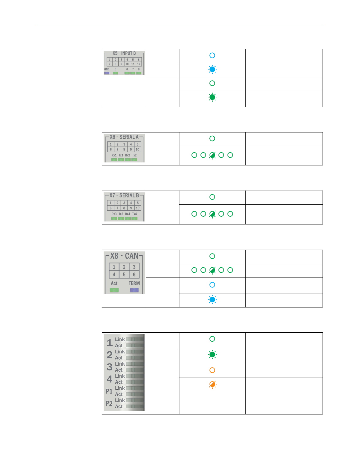
X5 – INPUT B
OPERATION 8
GND GND S2 switch to GND ISO
GND S2 switch to GND
5
6
7
8
X6 – SERIAL A
Table 4: SERIAL status LEDs
Rx1
Tx1
Rx2
Tx2
X7 – SERIAL B
Table 5: SERIAL status LEDs
Rx3
Tx3
Rx4
Tx4
X8 – CAN
Table 6: CAN status LEDs
Act No signal activity
Current signal level = low
Current signal level = high
No signal activity
Signal activity
No signal activity
Signal activity
TERM Termination resistor not acti‐
X9 – X12 ETHERNET 1 – 4, fieldbus 1 – 2
Table 7: ETHERNET and FIELDBUS status LEDs
Link Connection not established with
Act No activity
Signal activity
vated
Termination resistor activated
Ethernet
ETH1-ETH4 only. Connection
established with Ethernet
Data transmission via Ethernet
8020764/ZM92/2017-08-04 | SICK OP E RA T IN G I N ST R UC T IO N S | SIM2000ST
Subject to change without notice
29
Page 30
8 OPERATION
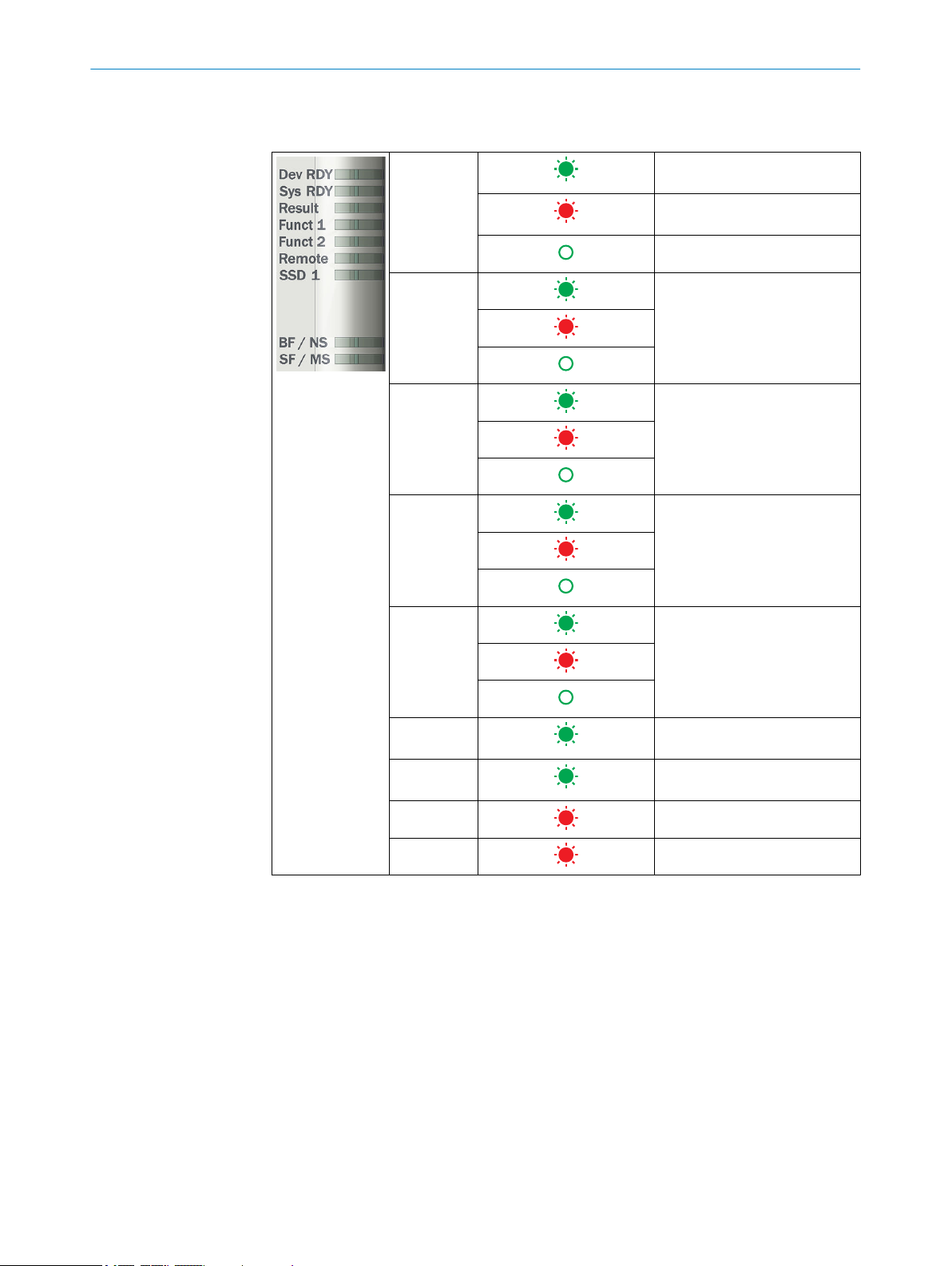
Device status
Table 8: Device status indicators
Dev RDY Runlevel READY, no errors
detected
Runlevel READY, boot process
error
Runlevel READY not reached
Sys RDY User-defined, configurable with
SICK AppSpace
Result User-defined, configurable with
SICK AppSpace
Funct 1 User-defined, configurable with
SICK AppSpace
Funct 2 User-defined, configurable with
SICK AppSpace
Remote Remote maintenance active.
Currently not supported
SSD 1 Internal SSD connected.
Currently not supported
BF / NS Bus error (fieldbus)
SF / MS System error (fieldbus)
30
O PE R AT I NG IN S TR U CT I ON S | SIM2000ST 8020764/ZM92/2017-08-04 | SICK
Subject to change without notice
Page 31

9 Maintenance
9.1 Cleaning
NOTICE
Equipment damage due to improper cleaning.
Improper cleaning may result in equipment damage.
■
■
b
9.2 Maintenance
During operation, the device works maintenance-free.
MAINTENANCE 9
Only use recommended cleaning agents.
Never use sharp objects for cleaning.
The device must be cleaned regularly from the outside to guarantee heat dissipa‐
tion and therefore operation. Particular attention must be paid to ensure that the
cooling fins are free from dust and dirt. Clean using a dry towel or an industrial
vacuum cleaner. Do not use cleaning agents.
Depending on the assignment location, the following preventive maintenance tasks
may be required for the device at regular intervals:
Table 9: Maintenance schedule
Maintenance work Interval To be carried out
by
Check that the unused connections
are sealed with blind plugs
Interval depends on ambient condi‐
tions and climate. Recommended: At
least every 6 months.
Specialist
8020764/ZM92/2017-08-04 | SICK OP E RA T IN G I N ST R UC T IO N S | SIM2000ST
Subject to change without notice
31
Page 32

10 DECOMMISSIONING
10 Decommissioning
10.1 Disposal
CAUTION
Risk of injury due to hot device surface.
The surface of the device can become hot during operation.
Before commencing disassembly, switch off the device and allow it to cool down
b
as necessary.
Any device which can no longer be used must be disposed of in an environmentally
friendly manner in accordance with the applicable country-specific waste disposal regu‐
lations. Do not dispose of the product along with household waste.
NOTICE
Danger to the environment due to improper disposal of the device.
Disposing of devices improperly may cause damage to the environment.
Therefore, observe the following information:
Always observe the valid regulations on environmental protection.
b
Separate the recyclable materials by type and place them in recycling containers.
b
32
O PE R AT I NG IN S TR U CT I ON S | SIM2000ST 8020764/ZM92/2017-08-04 | SICK
Subject to change without notice
Page 33

11 Technical data
NOTE
The relevant online data sheet for your product, including technical data, dimensional
drawing, and connection diagrams can be downloaded, saved, and printed at:
www.sick.com/SIM2000
b
11.1 Features
Feature Parameter
Task Data recording, evaluation, and archiving
Supported devices/excerpt Encoders, code readers, laser scanners, photoelectric sensors,
Technology Embedded hardware architecture:
Random Access Memory 2 GB
Flash memory 512 MB in total, 427 MB of which available for applications
Memory card (optional) Industry-grade microSD memory card (flash card), max. 16 GB
Programming software SICK AppStudio
TECHNICAL DATA 11
etc.
4-core PowerPC CPU
•
FPGA for I/O handling
•
Dedicated fieldbus controller
•
Software:
Can be programmed within the SICK AppSpace environment
•
11.2 Interfaces
Feature Parameter
Data storage and retrieval Image and data logging via microSD memory card, inter‐
nal RAM, and external FTP
Serial (RS-232/RS-422/RS-485)
Quantity 4, also configurable as an encoder port
Function RS-232 / RS-422 / RS-485
Maximum data transmission rate RS-232: 115.2 kBaud
RS-422: 2 MBaud
RS-485: 2 MBaud
Fieldbus
Quantity 2
Function Ethernet-based fieldbus
Data transmission rate 10/100 Mbit/s
Protocol ProfiNet, Ethernet/IP, EtherCAT
Ethernet
Quantity 4
Function Host, AUX, image transmission
Data transmission rate 4 x [10/100/1,000 Mbit/s]
Protocol TCP/IP, FTP (image transmission)
CAN
Quantity 1
8020764/ZM92/2017-08-04 | SICK OP E RA T IN G I N ST R UC T IO N S | SIM2000ST
Subject to change without notice
33
Page 34

11 TECHNICAL DATA
Feature Parameter
Function SICK CAN sensor network (master/slave, multiplexer/
server) with termination resistor which can be activated
1 x CAN (IN/OUT) not isolated
Data transmission rate 20 kbit/s to 1 Mbit/s
Protocol CSN (SICK CAN sensor network)
IO-Link master
Quantity 4 x IO-Link to X1 male connector
Data transmission rate max. 230 kBaud
Protocol IO-Link master 1.1
Digital switching inputs/outputs
X1 4 configurable inputs/
outputs incl. IO-Link
X3 4 isolated outputs (high side)
X4 4 isolated inputs
X5 4 isolated inputs
USB AUX (USB 2.0) for configuration/diagnostics
4 inputs
11.3 Mechanics and electronics
Feature Parameter
Optical indicators 31 x green status indicators
Operating elements 1 selector switch present under the servicing panel
Electrical connection X1 – IO-Link, GPIOs: spring terminals
Supply voltage 24 V DC, ± 10% ES1 in accordance with EN 62368-1 or SELV in
Power consumption Typ. 20 W, without connected sensors
Power output Max. 50 W (input A & B, IO-Link)
Output current for switch‐
ing outputs
Output current for supply
voltages
Housing material Aluminum die cast
Housing color Light blue (RAL 5012)
Protection class III
Weight without accessories 1,532 g
Dimensions (W x D x H) 196 x 137 x 81 mm
3 x blue status indicators
6 x green Link indicators
6 x orange activity indicators
9 x red/green device status indicators
2 S1 and S2 switches for GND ISO/GND
X2 – POWER: spring terminals
X3 – OUTPUT: spring terminals
X4 – INPUT A: spring terminals
X5 – INPUT B: spring terminals
X6 – SERIAL A: spring terminals
X7 – SERIAL B: spring terminals
X8 – CAN: spring terminals
X9 to X14: RJ-45
accordance with EN 60950-1
X1: 100 mA per output
X3: 700 mA in total
X1: max. 700 mA
X4, X5: 700 mA in total
34
O PE R AT I NG IN S TR U CT I ON S | SIM2000ST 8020764/ZM92/2017-08-04 | SICK
Subject to change without notice
Page 35

11.4 Ambient data
Feature Parameter
Electromagnetic compati‐
bility (EMC)
Shock resistance EN 60068-2-6
Electrical safety EN 62368-1
Enclosure rating IP 20
Ambient operating temper‐
ature
Storage temperature -20 °C to +70 °C
Permissible relative humid‐
ity
TECHNICAL DATA 11
EN 61000-6-2:2005-08
EN 61000-6-4:2007+A1:2011
EN 61131-9:2013-12
0 °C to +50 °C, taking the described mounting requirements into
account, see "Mounting the device", page 16
90%, non-condensing
8020764/ZM92/2017-08-04 | SICK OP E RA T IN G I N ST R UC T IO N S | SIM2000ST
Subject to change without notice
35
Page 36

176.2 (6.94)
0
5.4 (0.21)
40.6 (1.60)
69.6 (2.74) 70.3
(2.77)
43.1
(1.7)
50
(1.97)
60.6
(2.39)
15
(0.59)
46.2
(1.82)
19.1
(0.75)
0
5.5
(0.22)
87.8 (3.46)
106.5 (4.19)
0.5 (0.02)
167.5 (6.59)
158.3 (6.23)
135.2 (5.32)
110.3 (4.34)
87.1 (3.43)
65.7 (2.59)
47.8 (1.88)
29.7 (1.17)
11.2 (0.44)
182 (7.17)
170 (6.69)
0
185 (7.28)
169 (6.65)
5.5 (0.22)
0
18 (3.27) 56.5 (2.23)
26.8
(1.06)
81
(3.19)
137
(5.39)
196 (7.72)
175.2 (6.90)
50.2
(1.98)
29.4
(1.16)
29.4
(1.16)
12 ANNEX
12 Annex
12.1 Dimensional drawings
Dimensions without accessories
All measurements in mm (inch).
36
O PE R AT I NG IN S TR U CT I ON S | SIM2000ST 8020764/ZM92/2017-08-04 | SICK
Subject to change without notice
Page 37

Dimensions with adapter plate
170 (6.69)
250 (9.84)
220 (8.66)
225 (8.86)
50 (1.97)
30
(1.18)
0,2 (0.01)
R 3,2
(.13)
R 3,2
(.13)
R 6,5
(.26)
196 (7.72)
ANNEX 12
12.2 Licenses
SICK uses open-source software. This software is licensed by the rights holders using
the following licenses among others: the free licenses GNU General Public License (GPL
Version2, GPL Version3) and GNU Lesser General Public License (LGPL), the MIT
license, zLib license, and the licenses derived from the BSD license.
This program is provided for general use, but WITHOUT ANY WARRANTY OF ANY KIND.
This warranty disclaimer also extends to the implicit assurance of marketability or suita‐
bility of the program for a particular purpose.
More details can be found in the GNU General Public License. View the complete
license texts here: www.sick.com/licensetexts. Printed copies of the license texts are
also available on request.
8020764/ZM92/2017-08-04 | SICK OP E RA T IN G I N ST R UC T IO N S | SIM2000ST
Subject to change without notice
37
Page 38

Further locations at www.sick.com
Australia
Phone +61 3 9457 0600
1800 334 802 – tollfree
E-Mail sales@sick.com.au
Austria
Phone +43 22 36 62 28 8-0
E-Mail office@sick.at
Belgium/Luxembourg
Phone +32 2 466 55 66
E-Mail info@sick.be
Brazil
Phone +55 11 3215-4900
E-Mail marketing@sick.com.br
Canada
Phone +1 905 771 14 44
E-Mail information@sick.com
Czech Republic
Phone +420 2 57 91 18 50
E-Mail sick@sick.cz
Chile
Phone +56 2 2274 7430
E-Mail info@schadler.com
China
Phone +86 20 2882 3600
E-Mail info.china@sick.net.cn
Denmark
Phone +45 45 82 64 00
E-Mail sick@sick.dk
Finland
Phone +358-9-2515 800
E-Mail sick@sick.fi
France
Phone +33 1 64 62 35 00
E-Mail info@sick.fr
Germany
Phone +49 211 5301-301
E-Mail info@sick.de
Hong Kong
Phone +852 2153 6300
E-Mail ghk@sick.com.hk
Hungary
Phone +36 1 371 2680
E-Mail office@sick.hu
India
Phone +91 22 6119 8900
E-Mail info@sick-india.com
Israel
Phone +972 4 6881000
E-Mail info@sick-sensors.com
Italy
Phone +39 02 274341
E-Mail info@sick.it
Japan
Phone +81 3 5309 2112
E-Mail support@sick.jp
Malaysia
Phone +6 03 8080 7425
E-Mail enquiry.my@sick.com
Mexico
Phone +52 (472) 748 9451
E-Mail mario.garcia@sick.com
Netherlands
Phone +31 30 2044 000
E-Mail info@sick.nl
New Zealand
Phone +64 9 415 0459
0800 222 278 – tollfree
E-Mail sales@sick.co.nz
Norway
Phone +47 67 81 50 00
E-Mail sick@sick.no
Poland
Phone +48 22 539 41 00
E-Mail info@sick.pl
Romania
Phone +40 356 171 120
E-Mail office@sick.ro
Russia
Phone +7 495 775 05 30
E-Mail info@sick.ru
Singapore
Phone +65 6744 3732
E-Mail sales.gsg@sick.com
Slovakia
Phone +421 482 901201
E-Mail mail@sick-sk.sk
Slovenia
Phone +386 591 788 49
E-Mail office@sick.si
South Africa
Phone +27 11 472 3733
E-Mail info@sickautomation.co.za
South Korea
Phone +82 2 786 6321
E-Mail info@sickkorea.net
Spain
Phone +34 93 480 31 00
E-Mail info@sick.es
Sweden
Phone +46 10 110 10 00
E-Mail info@sick.se
Switzerland
Phone +41 41 619 29 39
E-Mail contact@sick.ch
Taiwan
Phone +886 2 2375-6288
E-Mail sales@sick.com.tw
Thailand
Phone +66 2645 0009
E-Mail Ronnie.Lim@sick.com
Turkey
Phone +90 216 528 50 00
E-Mail info@sick.com.tr
United Arab Emirates
Phone +971 4 88 65 878
E-Mail info@sick.ae
United Kingdom
Phone +44 1727 831121
E-Mail info@sick.co.uk
USA
Phone +1 800 325 7425
E-Mail info@sick.com
Vietnam
Phone +84 945452999
E-Mail Ngo.Duy.Linh@sick.com
8020764/ZM92/2017-08-04/en
SICK AG | Waldkirch | Germany | www.sick.com
 Loading...