

Page 1

SIM1000 FXA
Sensor Integration Machine
O P E R A T I N G I N S T R U C T I O N S
Page 2

Described product
SIM1000 FXA
Manufacturer
SICK AG
Erwin-Sick-Str. 1
79183 Waldkirch
Germany
Legal information
This work is protected by copyright. Any rights derived from the copyright shall be
reserved for SICK AG. Reproduction of this document or parts of this document is only
permissible within the limits of the legal determination of Copyright Law. Any modifica‐
tion, abridgment or translation of this document is prohibited without the express writ‐
ten permission of SICK AG.
The trademarks stated in this document are the property of their respective owner.
© SICK AG. All rights reserved.
Original document
This document is an original document of SICK AG.
2
O PE R AT I NG IN S TR U CT I ON S | SIM1000 FX A 8023299//2019-03-13 | SICK
Subject to change without notice
Page 3

Contents
CONTENTS
1 About this document........................................................................ 5
1.1 Information on the operating instructions.............................................. 5
1.2 Explanation of symbols............................................................................ 5
1.3 Further information................................................................................... 6
1.4 SICK service.............................................................................................. 6
2 Safety information............................................................................ 7
2.1 General safety notes................................................................................ 7
2.2 Intended use............................................................................................. 7
2.3 Improper use............................................................................................. 7
2.4 Internet protocol (IP) technology.............................................................. 8
2.5 Limitation of liability................................................................................. 8
2.6 Modifications and conversions................................................................ 8
2.7 Requirements for skilled persons and operating personnel.................. 9
2.8 Operational safety and particular hazards.............................................. 9
3 Product description........................................................................... 11
3.1 Device view................................................................................................ 11
3.2 Functionality.............................................................................................. 11
3.3 SICK AppSpace......................................................................................... 11
3.4 Preset ETHERNET interfaces................................................................... 12
4 Transport and storage....................................................................... 13
4.1 Transport................................................................................................... 13
4.2 Transport inspection................................................................................. 13
4.3 Storage...................................................................................................... 13
5 Mounting............................................................................................. 14
5.1 Overview of mounting procedure............................................................. 14
5.2 Scope of delivery....................................................................................... 14
5.3 Mounting the device................................................................................. 14
6 Electrical installation........................................................................ 16
6.1 Important notes........................................................................................ 16
6.2 Preparing the electrical installation......................................................... 17
6.3 Assembling the cables (optional)............................................................ 18
6.4 Overview of connections.......................................................................... 18
6.5 Pin allocation of the connections............................................................ 19
6.5.1 Terminal block 1 and 2............................................................ 19
6.5.2 Terminal block 3 and 4............................................................ 20
6.5.3 Ethernet connections.............................................................. 20
6.6 Connecting peripheral devices................................................................ 21
6.7 Connecting voltage supply....................................................................... 21
7 Commissioning.................................................................................. 22
8023299//2019-03-13 | SICK OP E RA T IN G I N ST R UC T IO N S | SIM1000 FXA
Subject to change without notice
3
Page 4

CONTENTS
7.1 Preparatory commissioning..................................................................... 22
8 Operation............................................................................................ 23
8.1 Status LEDs............................................................................................... 23
8.1.1 Situation and function of the LEDs......................................... 23
9 Maintenance...................................................................................... 25
9.1 Maintenance schedule............................................................................. 25
9.2 Cleaning..................................................................................................... 25
10 Decommissioning............................................................................. 26
10.1 Removing the module............................................................................... 26
10.2 Disposal..................................................................................................... 26
11 Technical data.................................................................................... 27
11.1 Features.................................................................................................... 27
11.2 Interfaces.................................................................................................. 27
11.3 Mechanics and electronics...................................................................... 28
11.4 Ambient data............................................................................................. 28
12 Annex.................................................................................................. 29
12.1 Dimensional drawings.............................................................................. 29
12.2 Licenses.................................................................................................... 29
4
O PE R AT I NG IN S TR U CT I ON S | SIM1000 FX A 8023299//2019-03-13 | SICK
Subject to change without notice
Page 5
1 About this document
1.1 Information on the operating instructions
These operating instructions provide important information on how to use devices from
SICK AG.
Prerequisites for safe work are:
Compliance with all safety notes and handling instructions supplied.
•
Compliance with local work safety regulations and general safety regulations for
•
device applications
The operating instructions are intended to be used by qualified personnel and electrical
specialists.
NOTE
Read these operating instructions carefully to familiarize yourself with the device and its
functions before commencing any work.
The instructions constitute an integral part of the product and are to be stored in the
immediate vicinity of the device so they remain accessible to staff at all times. Should
the device be passed on to a third party, these operating instructions should be handed
over with it.
ABOUT THIS DOCUMENT 1
These operating instructions do not provide information on operating the machine or
system in which the device is integrated. For information about this, refer to the operat‐
ing instructions of the specific machine.
1.2 Explanation of symbols
Warnings and important information in this document are labeled with symbols. The
warnings are introduced by signal words that indicate the extent of the danger. These
warnings must be observed at all times and care must be taken to avoid accidents, per‐
sonal injury, and material damage.
DANGER
… indicates a situation of imminent danger, which will lead to a fatality or serious
injuries if not prevented.
WARNING
… indicates a potentially dangerous situation, which may lead to a fatality or serious
injuries if not prevented.
CAUTION
… indicates a potentially dangerous situation, which may lead to minor/slight injuries if
not prevented.
NOTICE
… indicates a potentially harmful situation, which may lead to material damage if not
prevented.
NOTE
… highlights useful tips and recommendations as well as information for efficient and
trouble-free operation.
8023299//2019-03-13 | SICK OP E RA T IN G I N ST R UC T IO N S | SIM1000 FXA
Subject to change without notice
5
Page 6

1 ABOUT THIS DOCUMENT
1.3 Further information
NOTE
Further documentation for the device can be found on the online product page at:
www.sick.com/SIM10xx
•
There, additional information has been provided depending on the product, such as:
Model-specific online data sheets for device variants, containing technical data,
•
dimensional drawing, and specification diagrams
EU declarations of conformity for the product family
•
Dimensional drawings and 3D CAD dimension models in various electronic for‐
•
mats
This documentation, in English and German and other languages if applicable
•
Other publications related to the devices described here
•
Publications dealing with accessories
•
1.4 SICK service
If you require any technical information, our SICK Service will be happy to help. To find
your agency, see the final page of this document.
NOTE
Before calling, make a note of all type label data such as type code, serial number, etc.,
to ensure faster processing.
6
O PE R AT I NG IN S TR U CT I ON S | SIM1000 FX A 8023299//2019-03-13 | SICK
Subject to change without notice
Page 7

2 Safety information
2.1 General safety notes
The following safety notes must always be observed regardless of specific application
conditions:
The device must only be mounted, commissioned, operated, and maintained by
•
professionally qualified safety personnel.
Electrical connections with peripheral devices must only be made when the volt‐
•
age supply is disconnected.
The device is only to be operated when mounted in a fixed position.
•
The device voltage supply must be protected in accordance with the specifications.
•
The specified ambient conditions must be observed at all times.
•
The electrical connections to peripheral devices must be screwed on correctly.
•
The pin assignment of pre-assembled cables must be checked and adjusted if
•
necessary.
These operating instructions must be made available to the operating personnel
•
and kept ready to hand.
2.2 Intended use
SAFETY INFORMATION 2
The device is a programmable control and evaluation unit for sensors. The device also
acts as a link between system and plant controls, and the connected terminal devices.
The device is mainly used in an industrial environment in production, testing, and con‐
trol. Other applications are possible depending on the device-specific properties. When
using the device in a mobile application, make sure the floor is flat and smooth and
avoid door sills.
The device is programmed on a PC by using the development environment software
SICK AppSpace. Depending on the application, a browser-based, graphical user inter‐
face (HMI) can be created, which provides opportunities defined by the application
developer to influence an application at operator level. The device is connected to
peripherals via Ethernet interfaces and other interfaces.
The device offers various interfaces for controlling, programming, and operating pur‐
poses, which can be activated as necessary via development environments, control sys‐
tems (programmable logic controllers), or applications. However, configuration, pro‐
gramming, and control requires various technical skills, depending on how the device is
connected and used.
2.3 Improper use
Any use outside of the stated areas, in particular use outside of the technical specifica‐
tions and the requirements for intended use, will be deemed to be incorrect use.
•
•
•
The device does not constitute a safety component in accordance with the respec‐
tive applicable safety standards for machines.
The device must not be used in explosion-hazardous areas, in corrosive environ‐
ments or under extreme environmental conditions.
Any use of accessories not specifically approved by SICK AG is at your own risk.
8023299//2019-03-13 | SICK OP E RA T IN G I N ST R UC T IO N S | SIM1000 FXA
Subject to change without notice
7
Page 8
2 SAFETY INFORMATION
WARNING
Danger due to improper use!
Any improper use can result in dangerous situations.
Therefore, observe the following information:
■
Device should be used only in accordance with its intended use.
■
All information in these operating instructions must be strictly observed.
2.4 Internet protocol (IP) technology
NOTE
SICK uses standard IP technology in its products. The emphasis is placed on availability
of products and services.
SICK always assumes the following prerequisites:
The customer ensures the integrity and confidentiality of the data and rights
•
affected by its own use of the aforementioned products.
In all cases, the customer implements the appropriate security measures, such as
•
network separation, firewalls, virus protection, and patch management.
2.5 Limitation of liability
Relevant standards and regulations, the latest technological developments, and our
many years of knowledge and experience have all been taken into account when com‐
piling the data and information contained in these operating instructions. The manufac‐
turer accepts no liability for damage caused by:
■
Non-adherence to the product documentation (e.g., operating instructions)
■
Incorrect use
■
Use of untrained staff
■
Unauthorized conversions
■
Technical modifications
■
Use of unauthorized spare parts, consumables, and accessories
With special variants, where optional extras have been ordered, or owing to the latest
technical changes, the actual scope of delivery may vary from the features and illustra‐
tions shown here.
NOTE
The product is a programmable device. The respective programmer is therefore respon‐
sible for his/her programming work and the resultant operation of the device. The liabil‐
ity and warranty of SICK AG is limited to the device specification (hardware functionality
and any programming interfaces) according to the agreed conditions. SICK AG will
therefore not be liable, among other things, for any damages resulting from the pro‐
gramming of the product by the customer or third parties.
2.6 Modifications and conversions
NOTICE
Modifications and conversions to the device may result in unforeseeable dangers.
Interrupting or modifying the device or SICK software will invalidate any warranty claims
against SICK AG. This applies in particular to opening the housing, even as part of
mounting and electrical installation.
8
O PE R AT I NG IN S TR U CT I ON S | SIM1000 FX A 8023299//2019-03-13 | SICK
Subject to change without notice
Page 9

2.7 Requirements for skilled persons and operating personnel
WARNING
Risk of injury due to insufficient training.
Improper handling of the device may result in considerable personal injury and material
damage.
■
All work must only ever be carried out by the stipulated persons.
This product documentation refers to the following qualification requirements for the
various activities associated with the device:
■
Instructed personnel have been briefed by the operator about the tasks assigned
to them and about potential dangers arising from improper action.
■
Skilled personnel have the specialist training, skills, and experience, as well as
knowledge of the relevant regulations, to be able to perform tasks delegated to
them and to detect and avoid any potential dangers independently.
■
Electricians have the specialist training, skills, and experience, as well as knowl‐
edge of the relevant standards and provisions to be able to carry out work on elec‐
trical systems and to detect and avoid any potential dangers independently. In Ger‐
many, electricians must meet the specifications of the BGV A3 Work Safety Regu‐
lations (e.g. Master Electrician). Other relevant regulations applicable in other
countries must be observed.
SAFETY INFORMATION 2
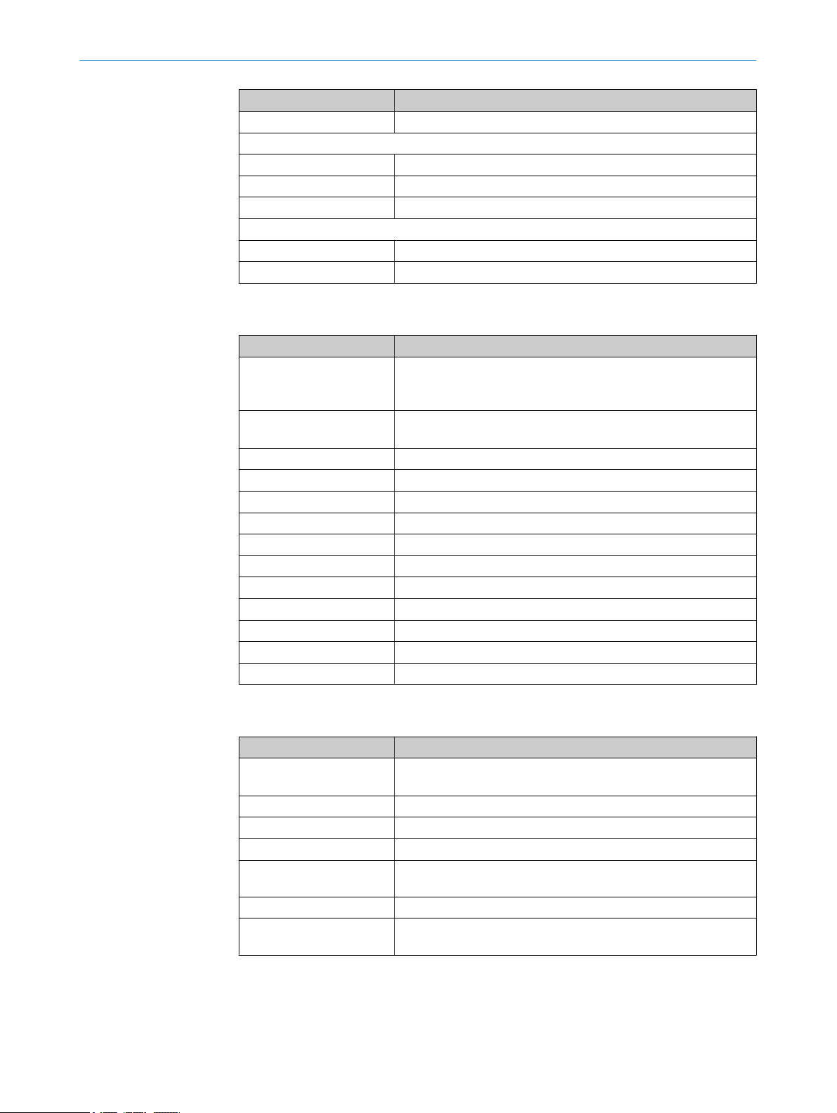
The following qualifications are required for various activities:
Table 1: Activities and technical requirements
Activities Qualification
Mounting, maintenance
Electrical installation,
device replacement
Basic practical technical training
■
Knowledge of the current safety regulations in the workplace
■
Practical electrical training
■
Knowledge of current electrical safety regulations
■
Knowledge of the operation and control of the devices in their
■
particular application
Commissioning, configura‐
tion
Basic knowledge of the WindowsTM operating system in use
■
Basic knowledge of the design and setup of the described con‐
■
nections and interfaces
Basic knowledge of data transmission
■
Operation of the device for
the particular application
Knowledge of the operation and control of the devices in their
■
particular application
Knowledge of the software and hardware environment for the
■
particular application
2.8 Operational safety and particular hazards
Please observe the safety notes and the warnings listed here and in other chapters of
this product documentation to reduce the possibility of risks to health and avoid dan‐
gerous situations.
The product is fitted with LEDs in risk group 0. The accessible radiation from these
LEDs does not pose a danger to the eyes or skin.
8023299//2019-03-13 | SICK OP E RA T IN G I N ST R UC T IO N S | SIM1000 FXA
Subject to change without notice
9
Page 10

2 SAFETY INFORMATION
WARNING
Electrical voltage!
Electrical voltage can cause severe injury or death.
■
■
■
■
■
WARNING
Risk of injury and damage caused by potential equalization currents!
Improper grounding can lead to dangerous equipotential bonding currents, which may
in turn lead to dangerous voltages on metallic surfaces, such as the housing. Electrical
voltage can cause severe injury or death.
■
■
■
Work on electrical systems must only be performed by qualified electricians.
The power supply must be disconnected when attaching and detaching electrical
connections.
The product must only be connected to a voltage supply as set out in the require‐
ments in the operating instructions.
National and regional regulations must be complied with.
Safety requirements relating to work on electrical systems must be complied with.
Work on electrical systems must only be performed by qualified electricians.
Follow the notes in the operating instructions.
Install the grounding for the product and the system in accordance with national
and regional regulations.
10
O PE R AT I NG IN S TR U CT I ON S | SIM1000 FX A 8023299//2019-03-13 | SICK
Subject to change without notice
Page 11

3 Product description
1
2
3
3.1 Device view
PRODUCT DESCRIPTION 3
1
2
3
3.2 Functionality
The SIM1000 FXA Sensor Integration Machine – part of the SICK AppSpace ecosystem
– is opening up new possibilities for application solutions.
It can read, evaluate, archive, and transmit data from a number of different sensors.
The Ethernet interfaces with OPC UA and MQTT provide preprocessed data (edge com‐
puting) for cloud computing.
The HMI and data visualization features can be provided on any browser-enabled note‐
book, PC, or tablet. The app is developed in SICK AppStudio .
3.3
SICK AppSpace
Detailed instructions on the SICK AppStudio as well as programming the device can be
found at supportportal.sick.com.
Connections for switching input/output, IO-Link, CAN, and voltage supply
Serial connections
Ethernet connections
8023299//2019-03-13 | SICK OP E RA T IN G I N ST R UC T IO N S | SIM1000 FXA
Subject to change without notice
11
Page 12

3 PRODUCT DESCRIPTION
3.4 Preset ETHERNET interfaces
NOTE
Preset IP addresses of the ETHERNET interfaces:
Port 1: 192.168.0.1
•
Port 2: 192.168.1.1
•
Port 3: 192.168.2.1
•
Port 4: 192.168.3.1
•
When expanding the GigE interfaces with one or more Ethernet switches, it is essential
to use only jumbo-frame compatible GigE switches. Switches limited to just 100 MB do
not support the data packet mode used by cameras and can cause transmission
errors.
Changing the IP addresses
The individual IP addresses can be changed using the SICK SOPAS ET PC tool. This is
described in detail in the “SIM Getting Started Guide”, which is available for download
from the SICK AppSpace area of the SICK Support Portal. This guide also includes fur‐
ther notes on how to connect SICK sensors and the SICK picoCam and midiCam cam‐
eras to the Ethernet interfaces.
12
O PE R AT I NG IN S TR U CT I ON S | SIM1000 FX A 8023299//2019-03-13 | SICK
Subject to change without notice
Page 13

4 Transport and storage
4.1 Transport
For your own safety, please read and observe the following notes:
NOTICE
Damage to the product due to improper transport.
■
The device must be packaged for transport with protection against shock and
damp.
■
Recommendation: Use the original packaging as it provides the best protection.
■
Transport should be performed by trained specialist staff only.
■
The utmost care and attention is required at all times during unloading and trans‐
portation on company premises.
■
Note the symbols on the packaging.
■
Do not remove packaging until immediately before you start mounting.
TRANSPORT AND STORAGE 4
4.2
Transport inspection
4.3 Storage
Immediately upon receipt in Goods-in, check the delivery for completeness and for any
damage that may have occurred in transit. In the case of transit damage that is visible
externally, proceed as follows:
■
Do not accept the delivery or only do so conditionally.
■
Note the scope of damage on the transport documents or on the transport com‐
pany's delivery note.
■
File a complaint.
NOTE
Complaints regarding defects should be filed as soon as these are detected. Damage
claims are only valid before the applicable complaint deadlines.
Store the device under the following conditions:
■
Recommendation: Use the original packaging.
■
Do not store outdoors.
■
Store in a dry area that is protected from dust.
■
So that any residual damp can evaporate, do not package in airtight containers.
■
Do not expose to any aggressive substances.
■
Protect from sunlight.
■
Avoid mechanical shocks.
■
Storage temperature: see "Technical data", page 27.
■
For storage periods of longer than 3 months, check the general condition of all
components and packaging on a regular basis.
8023299//2019-03-13 | SICK OP E RA T IN G I N ST R UC T IO N S | SIM1000 FXA
Subject to change without notice
13
Page 14

5 MOUNTING
5 Mounting
5.1 Overview of mounting procedure
NOTICE
Damage to device through improper mounting.
Mount the device in an environment corresponding to enclosure rating IP54
(EN 60529), e.g., inside a control cabinet with enclosure rating IP54.
NOTE
The mounting procedure described here for the device meets the requirements for use
in the target system.
Additional or different requirements may become necessary in the laboratory and dur‐
ing preparation, and should be taken into account as necessary, see "Commissioning",
page 22. If you have any questions or anything remains unclear in this regard, please
contact our service team.
Mounting the device.
•
Connect the cables.
•
Connecting peripheral devices.
•
Connecting the voltage supply.
•
5.2 Scope of delivery
SIM1000 FXA
•
Safety note
•
Optional: ordered accessories
•
5.3 Mounting the device
Mount the device in accordance with EN 50274.
•
Ensure suitable ESD protective measures during mounting.
•
Implement suitable measures to prevent any foreign bodies from entering the con‐
•
nector openings or ventilation slots.
The module is housed in a 67.5 mm wide housing for standard 35 mm rails in
•
accordance with EN 60715 (mounting rail).
Install the module in the control cabinet in such a way that the minimum distance
•
to the control cabinet is adhered to. This distance is 50 mm above and below the
module, and 25 mm to the front and back.
Mount the module vertically. The ventilation slots must be positioned at the top
•
and bottom.
Mount the module in such a way as to allow vertical air circulation.
•
14
O PE R AT I NG IN S TR U CT I ON S | SIM1000 FX A 8023299//2019-03-13 | SICK
Subject to change without notice
Page 15

MOUNTING
Figure 1: Mounting the device, illustration only
Mounting rail
1
Grounding clip
2
Direction of engagement with the mounting rail
3
1. Make sure that the voltage supply is switched off.
2. Hook the device onto the DIN mounting rail.
3. The grounding clip must sit flush against the mounting rail so that it is secure and
can conduct electricity effectively.
4. Snap the module into place on the mounting rail by applying a slight pressure in
the direction of the arrow.
5. Mount the end pieces on the left and right side of the module.
5
8023299//2019-03-13 | SICK OP E RA T IN G I N ST R UC T IO N S | SIM1000 FXA
Subject to change without notice
15
Page 16
6 ELECTRICAL INSTALLATION
6 Electrical installation
6.1 Important notes
DANGER
Danger from electrical voltage.
Danger posed by the machine starting up unexpectedly.
Disconnect the power for the entire system/machine.
•
Prevent the system from starting unexpectedly while you are connecting the
•
devices!
WARNING
Risk of injury and damage caused by electrical current!
Due to equipotential bonding currents, incorrect earthing can lead to the following dan‐
gers and faults: Voltage is applied to the metal housing, cable fires due to cable shields
heating up, the product and other devices become damaged.
■
Generate the same ground potential at all grounding points.
NOTICE
Device damage due to improper supply voltage!
■
Only operate the device with the specified supply voltage.
■
The voltage supply and all connected signals must meet the requirements for
extra-low voltages with safe separation (SELV, PELV) as specified in EN 60664 and
EN 50178 (Electronic equipment for use in power installations).
Carry out the electrical installation work in conformity with EN 60204-1.
•
The external voltage supply for the devices must be capable of bridging short-term
•
power outages of 20 ms as specified in EN 60204-1, for example.
Make sure the device and the voltage supplies are all connected to the same
•
ground.
Connect the shielding of all data lines (Ethernet, CAN, serial) directly to the func‐
•
tional earth (FE) at the control cabinet entry point.
NOTE
Layout of data cables
■
Use screened data cables with twisted-pair wires.
■
Implement the screening design correctly and completely.
■
To avoid interference, e.g. from switching power supplies, motors, clocked drives,
and contactors, always use cables and layouts that are suitable for EMC.
■
Do not lay cables over long distances in parallel with power supply cables and
motor cables in cable channels.
16
EMC measures
Electromagnetic influences can interfere with signal transmissions and interrupt com‐
munications. To minimize electromagnetic influences, it is necessary to implement the
following measures:
Connect the mounting rail to functional earth (FE).
•
Ensure sufficient equipotential bonding of the connection points for the shielding.
•
Ensure compliance with the applicable standards and directives.
O PE R AT I NG IN S TR U CT I ON S | SIM1000 FX A 8023299//2019-03-13 | SICK
Subject to change without notice
Page 17
1
2
3
ELECTRICAL INSTALLATION 6
Connect all inactive metal parts (doors and housing of the control cabinet, DIN
•
mounting rails, etc.) to the ground potential.
Always connect the cable shielding to the ground connection across a large area
•
at both ends.
Use suitable cable clamps to connect the shielding of the shielded cables to the
•
ground potential directly at the access to the system (control cabinet, frame, DIN
mounting rail). The cable clamps must reach all the way around the cable shield‐
ing.
Use suitable cable clamps to connect the cable shielding to the ground potential,
•
once again as close as possible to the main module (e.g., on the DIN mounting
rail). The cable clamps must reach all the way around the cable shielding.
Keep the cable ends from which the insulation has been stripped as short as pos‐
•
sible.
Insulate the end of the shielding braid, for example using a suitable heat-shrink‐
•
able sleeve.
Figure 2: Connecting the cable shielding to the mounting rail, example
Mounting rail
1
Cable
2
Heat-shrinkable sleeve
3
6.2 Preparing the electrical installation
To carry out the electrical installation, you will need:
Connection cables for the peripheral devices, including the corresponding data
•
sheets
Voltage supply cable
•
If customers assemble the cables: crimping tool, ferrules, soldering iron, and other
•
installation material
8023299//2019-03-13 | SICK OP E RA T IN G I N ST R UC T IO N S | SIM1000 FXA
Subject to change without notice
17
Page 18

6 ELECTRICAL INSTALLATION
6.3 Assembling the cables (optional)
NOTE
For a list of cables suitable for use with the device, visit supportportal.sick.com or
www.sick.com. Customer assembly of the cables is only necessary in special cases.
Ensure a sufficient length of cable is provided, e.g. for strain-relief clamps.
NOTICE
Risk of damage/malfunction due to incorrect PIN assignment
Incorrect wiring of the male connectors/female connectors can lead to damage to or
malfunctions in the system.
■
Observe data sheets provided by the cable manufacturer.
■
Observe the pin assignment.
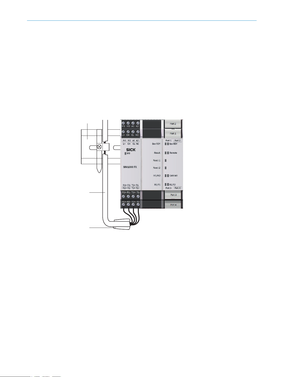
6.4 Overview of connections
18
Figure 3: Overview of connections
Terminal block 1 and 2
1
Terminal block 3 and 4
2
Ethernet connections
3
O PE R AT I NG IN S TR U CT I ON S | SIM1000 FX A 8023299//2019-03-13 | SICK
Subject to change without notice
Page 19
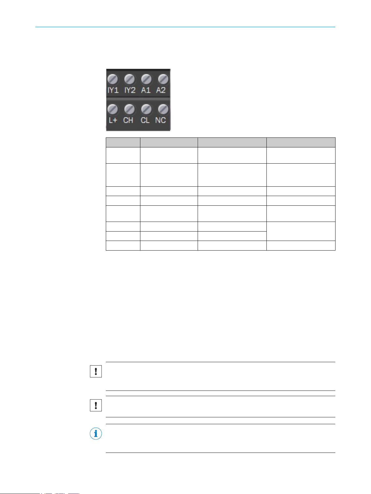
6.5 Pin allocation of the connections
6.5.1 Terminal block 1 and 2
Designation Signal Function Factory settings
IY1 Input 2 Switching input (not iso‐
IY2 C/Q or Input 1 / Out‐
put 1
A1 +24 V Supply voltage IN -
A2 GND Ground -
L+ +24 V Supply voltage for peripher‐
CH CAN_H CAN high Termination deactivated*
CL CAN_L CAN low
NC - Not connected
ELECTRICAL INSTALLATION 6
lated)
C/Q IO-link or configurable
switching input/output (not
isolated)
als, configurable
-
Configured as input
Deactivated
*Termination controllable via app
Additional notes
Switching output
Max. output current: 100 mA
•
Min. high output logic level: VCC – 3 V
•
Max. low output logic level: 3 V
•
Push/pull, NPN, PNP configurable
•
Switching inputs
Min. high input logic level: 12 V
•
Max. low input logic level: 4 V
•
Supply voltage, peripherals L +
Output current: 200 mA
•
NOTICE
Shielded CAN cables must be used. The shielding of the CAN cables must be connected
to functional earth.
NOTICE
IO-Link ground and CAN ground of the sensor must be connected to system ground A2.
NOTE
The SIM1000 FXA device is supplied with power from an external power supply unit via
the pins A1 and A2.
8023299//2019-03-13 | SICK OP E RA T IN G I N ST R UC T IO N S | SIM1000 FXA
Subject to change without notice
19
Page 20
ELECTRICAL INSTALLATION
6
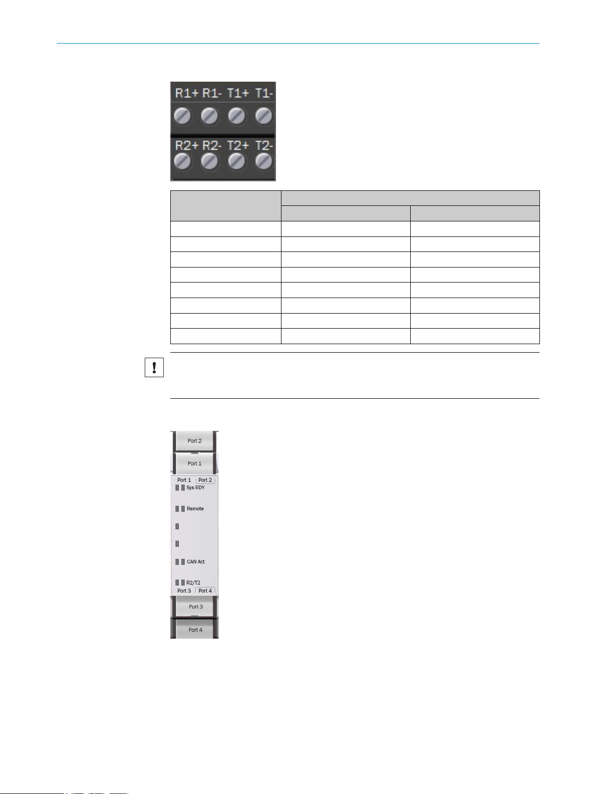
6.5.2 Terminal block 3 and 4
Designation Mode
R1+ R1+ -
R1- R1- -
T1+ T1+ Rx1+/Tx1+
T1- T1- Rx1-/Tx1-
R2+ R2+ -
R2- R2- -
T2+ T2+ Rx2+/Tx2+
T2- T2- Rx2-/Tx2-
RS-422 RS-485
NOTICE
Shielded cables must be used. The shielding of the cables must be connected to func‐
tional earth.
6.5.3 Ethernet connections
20
Port 1: 100 MBit/s
Port 2: 1 GBit/s
Port 3: 100 MBit/s
Port 4: 1 GBit/s
O PE R AT I NG IN S TR U CT I ON S | SIM1000 FX A 8023299//2019-03-13 | SICK
Subject to change without notice
Page 21
NOTICE
Shielded Ethernet cables must be used. The shielding of the Ethernet cables must be
connected to functional earth.
6.6 Connecting peripheral devices
The device can be connected to a wide range of sensors and cameras.
The required pin assignments can be found in the data sheets for the peripherals to be
connected as well as in the relevant connection descriptions, see "Pin allocation of the
connections", page 19.
1. Connect the cables to peripheral devices.
2. Route the cables to the device using installation materials (cable channels, cable
ties, etc.). When doing so, pay attention to cable strain relief.
3. Connect cables to the relevant device connections and screw together tightly.
6.7 Connecting voltage supply
NOTICE
Risk of damage to peripheral devices!
If peripheral devices are connected when the voltage supply is also applied, these
devices can become damaged.
■
Only connect peripheral devices when the voltage supply is disconnected.
ELECTRICAL INSTALLATION 6
1. Ensure that the voltage has been disconnected by the user.
2. Connect the voltage supply cable(s) to the device.
3. Lay the cable(s) with strain relief.
4. Have the user connect the voltage supply.
5. Have the user activate the voltage.
8023299//2019-03-13 | SICK OP E RA T IN G I N ST R UC T IO N S | SIM1000 FXA
Subject to change without notice
21
Page 22

7 COMMISSIONING
7 Commissioning
7.1 Preparatory commissioning
Commissioning for preparatory purposes and under laboratory conditions differs in
some respects from commissioning in the target system.
In general, all safety and hazard warnings applicable to mounting (see "Mounting",
page 14) and electrical installation see "Important notes", page 16 must also be
observed under laboratory conditions. In addition, further notes must be taken into con‐
sideration to guarantee the most effective preparation possible:
Only connect those devices to the product that you want to configure or program.
•
Operate the connected device in a controlled and contained network environment
•
for the time being to check network communication if necessary.
Note the company standards that apply to the use of checking and testing devices.
•
For initial programming, use ideal conditions for sensor or camera recognition.
•
Use the largest possible deviations from these ideal conditions to check the pro‐
•
gramming with respect to its error tolerance and reliability, and to determine error
limit values.
Procedure
1. Place the device on a non-slip base.
2. Connect the required peripheral devices, see "Connecting peripheral devices",
page 21.
3. Connect the network connection.
4. Connect the voltage supply.
5. Switch on the voltage supply.
22
O PE R AT I NG IN S TR U CT I ON S | SIM1000 FX A 8023299//2019-03-13 | SICK
Subject to change without notice
Page 23
8 Operation
8.1 Status LEDs
OPERATION 8
When the device is operating, the operational status of the connections is indicated
visually by status LEDs.
Using these status indicators, the operator can find out quickly and easily whether the
device and the peripherals are working properly or whether any faults or errors have
occurred.
Monitoring the visual indicators is part of the routine inspection carried out on the
device and the machine/plant area into which the device is incorporated.
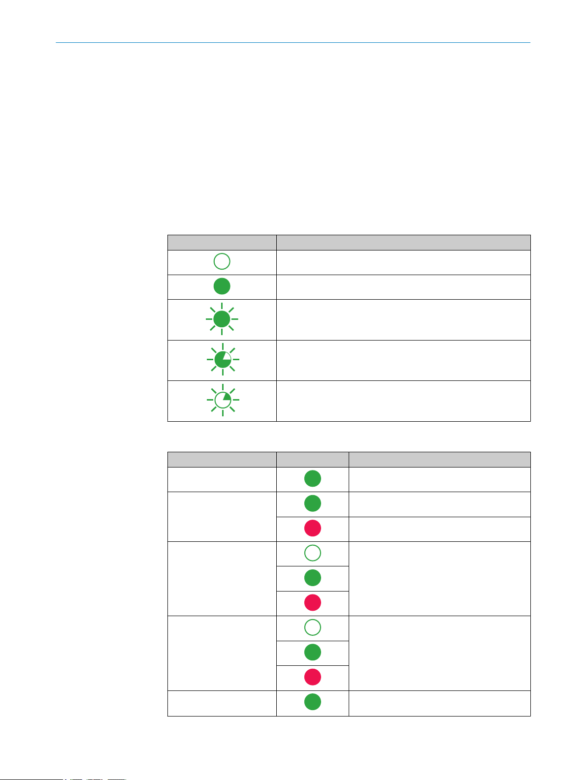
Meaning of symbols
Symbol Meaning
LED off
LED on
LED flashes
8.1.1 Situation and function of the LEDs
Designation LED behavior Description
*)
MS
Dev RDY Runlevel READY, no errors detected.*
Sys RDY User-defined, configurable using SICK App‐
Result User-defined, configurable using SICK App‐
LED goes out briefly
LED lights up briefly
Voltage connected.
Runlevel READY, boot process error.
Space.
Space.
Remote Remote maintenance active, not currently sup‐
ported.
8023299//2019-03-13 | SICK OP E RA T IN G I N ST R UC T IO N S | SIM1000 FXA
Subject to change without notice
23
Page 24

8 OPERATION
Designation LED behavior Description
Funct 1 User-defined, configurable using SICK App‐
Space.
Funct 2 User-defined, configurable using SICK App‐
Space.
IY1 / IY2
Voltage not applied to the connection.
CAN Act
R1 / T1
R2 / T2
Voltage applied.
No signal activity.
Voltage applied.
Signal activity.
Voltage not applied to the connection.
Signal activity.
Link Connection not established with Ethernet.
Connection established with Ethernet.
Act No activity.
Data transmission via Ethernet.
*Time delay before availability due to boot process (approx. 20 s)
*) Module status
24
O PE R AT I NG IN S TR U CT I ON S | SIM1000 FX A 8023299//2019-03-13 | SICK
Subject to change without notice
Page 25

9 Maintenance
9.1 Maintenance schedule
During operation, the device works maintenance-free.
9.2 Cleaning
NOTICE
Equipment damage due to improper cleaning.
Improper cleaning may result in equipment damage.
■
Only use recommended cleaning agents.
■
Never use sharp objects for cleaning.
The device must be cleaned regularly from the outside to guarantee heat dissipa‐
b
tion and therefore operation. Clean using a dry towel or an industrial vacuum
cleaner. Do not use cleaning agents.
MAINTENANCE 9
8023299//2019-03-13 | SICK OP E RA T IN G I N ST R UC T IO N S | SIM1000 FXA
Subject to change without notice
25
Page 26

10 DECOMMISSIONING
10 Decommissioning
10.1 Removing the module
Remove the plug-in terminals along with the wiring and the end pieces.
•
Push the module down at the back (1). With the module still pushed down, move it
•
in the direction of the arrow to remove it from the mounting rail (2).
10.2 Disposal
Figure 4: Removing the module, example
CAUTION
Risk of injury due to hot device surface.
The surface of the device can become hot during operation.
■
Before commencing disassembly, switch off the device and allow it to cool down
as necessary.
If a device can no longer be used, dispose of it in an environmentally friendly manner in
accordance with the applicable country-specific waste disposal regulations. Do not dis‐
pose of the product along with household waste.
NOTICE
Danger to the environment due to improper disposal of the device.
Disposing of devices improperly may cause damage to the environment.
Therefore, observe the following information:
■
Always observe the valid regulations on environmental protection.
■
Separate the recyclable materials by type and place them in recycling containers.
26
O PE R AT I NG IN S TR U CT I ON S | SIM1000 FX A 8023299//2019-03-13 | SICK
Subject to change without notice
Page 27

11 Technical data
NOTE
The relevant online data sheet for your product, including technical data, dimensional
drawing, and connection diagrams can be downloaded, saved, and printed from the
Internet:
www.sick.com/SIM10xx
•
11.1 Features
Feature Parameter
Task Data recording, evaluation, and archiving
Supported devices
(excerpt)
Technology Embedded hardware architecture:
Random Access Memory 1 GB
Flash memory 256 MB in total, 30 MB of which available for applications
Memory card, integrated Industrial-grade MicroSD memory card, 1 GB
Programming software SICK AppStudio
Sensor data processing According to SICK Algorithm API
TECHNICAL DATA 11
Encoders, code readers, RFID read/write devices, SICK LiDAR
scanners, SICK picoCam and midiCam
Dual-core ARM Cortex-A9 CPU with NEON accelerator
•
FPGA for I/O handling
•
Software:
Can be programmed within the SICK AppSpace environment
•
SICK Algorithm API
•
11.2 Interfaces
Feature Parameter
Data storage and retrieval Image and data logging via microSD memory card, internal RAM,
and external FTP
SERIAL (RS-422 / RS-485)
Number 2
Function RS-422 / RS-485
Maximum data transmis‐
sion rate
ETHERNET
Number 4
Function Host, image transmission
Data transmission rate Port 1, 3: 100 Mbit/s
Protocol TCP/IP, FTP (image transmission)
CAN
Number 1
Function SICK CAN sensor network (master/slave, multiplexer/server), ter‐
Data transmission rate 20 kbit/s ... 1 Mbit/s
RS-422: 2 MBaud
RS-485: 2 MBaud
Port 2, 4: 1 Gbit/s
mination controllable via app
8023299//2019-03-13 | SICK OP E RA T IN G I N ST R UC T IO N S | SIM1000 FXA
Subject to change without notice
27
Page 28
11 TECHNICAL DATA
Feature Parameter
Protocol CSN (SICK CAN sensor network)
IO-Link
Number 1
Function IO-Link Master V1.1
Data transmission rate max. 230 kBaud
Digital switching inputs/outputs
IYI: Switching input, max. frequency: 30 kHz
IY2: Switching input/output (configurable), max. frequency: 30 kHz
11.3 Mechanics and electronics
Feature Parameter
Optical indicators 7 x status indicators, front membrane, red/green
Electrical connection Terminal block 1 - 4: spring terminals
Supply voltage 24 V DC, -30% / +25%
Operating current Must be limited by external power supply unit to max. 2 A
Power consumption Max. 10.5 W, without connected sensors
Power output Max. 9 W total (all connections)
Output current IY2 Max. 100 mA
Output current L+ 200 mA (400 mA briefly when switched on)
Housing material Polycarbonate
Housing color Light gray (RAL 7035)
Protection class III (EN 61140:2016-05)
Weight 430 g (with spring terminals)
Dimensions (W x D x H) 67.5 mm x 96.5 mm x 120.6 mm
4 x status indicators, front membrane, green
4 x status indicators, Ethernet, orange/green
Ethernet connections: RJ - 45
11.4 Ambient data
Feature Parameter
Electromagnetic compati‐
bility (EMC)
Vibration resistance EN 60068-2-6:2008-02, EN 61131-2:2007-09
Shock resistance EN 60068-2-27:2009-05, EN 61131-2:2007-09
Enclosure rating IP20 as per EN 60529:1991-10 + A1:2000-02 + A2:2013-10
Ambient operating temper‐
ature
Storage temperature -25 °C ... +70 °C
Permissible relative humid‐
ity
28
O PE R AT I NG IN S TR U CT I ON S | SIM1000 FX A 8023299//2019-03-13 | SICK
EN 61000-6-2:2005-08
EN 61000-6-4:2007 + A1:2011
-25 °C ... +55 °C
90%, non-condensing
Subject to change without notice
Page 29

12 Annex
67.5 (2.66)
120.6 (4.75)
114.3 (4.5)
75.3 (2.96)
93.7 (3.69)
109 (4.29)
14.8 (0.58)
14.8 (0.58)
20
(0.79)20(0.79)
22.5
(0.89)
22.5
(0.89)
15.8 (0.62)
96.5 (3.80)
93.3 (3.67)
58 (2.28)
78 (3.07)
5.1
(0.20)
5.1
(0.20)
12.1 Dimensional drawings
Dimensions without accessories
All measurements in mm.
ANNEX 12
12.2 Licenses
SICK uses open-source software. This software is licensed by the rights holders using
the following licenses among others: the free licenses GNU General Public License (GPL
Version2, GPL Version3) and GNU Lesser General Public License (LGPL), the MIT
license, zLib license, and the licenses derived from the BSD license.
This program is provided for general use, but WITHOUT ANY WARRANTY OF ANY KIND.
This warranty disclaimer also extends to the implicit assurance of marketability or suit‐
ability of the program for a particular purpose.
More details can be found in the GNU General Public License. View the complete
license texts here: www.sick.com/licensetexts. Printed copies of the license texts are
also available on request.
8023299//2019-03-13 | SICK OP E RA T IN G I N ST R UC T IO N S | SIM1000 FXA
Subject to change without notice
29
Page 30

Further locations at www.sick.com
Australia
Phone +61 (3) 9457 0600
1800 33 48 02 – tollfree
E-Mail sales@sick.com.au
Austria
Phone +43 (0) 2236 62288-0
E-Mail office@sick.at
Belgium/Luxembourg
Phone +32 (0) 2 466 55 66
E-Mail info@sick.be
Brazil
Phone +55 11 3215-4900
E-Mail comercial@sick.com.br
Canada
Phone +1 905.771.1444
E-Mail cs.canada@sick.com
Czech Republic
Phone +420 2 57 91 18 50
E-Mail sick@sick.cz
Chile
Phone +56 (2) 2274 7430
E-Mail chile@sick.com
China
Phone +86 20 2882 3600
E-Mail info.china@sick.net.cn
Denmark
Phone +45 45 82 64 00
E-Mail sick@sick.dk
Finland
Phone +358-9-25 15 800
E-Mail sick@sick.fi
France
Phone +33 1 64 62 35 00
E-Mail info@sick.fr
Germany
Phone +49 (0) 2 11 53 01
E-Mail info@sick.de
Hong Kong
Phone +852 2153 6300
E-Mail ghk@sick.com.hk
Hungary
Phone +36 1 371 2680
E-Mail ertekesites@sick.hu
India
Phone +91-22-6119 8900
E-Mail info@sick-india.com
Israel
Phone +972-4-6881000
E-Mail info@sick-sensors.com
Italy
Phone +39 02 27 43 41
E-Mail info@sick.it
Japan
Phone +81 3 5309 2112
E-Mail support@sick.jp
Malaysia
Phone +603-8080 7425
E-Mail enquiry.my@sick.com
Mexico
Phone +52 (472) 748 9451
E-Mail mario.garcia@sick.com
Netherlands
Phone +31 (0) 30 229 25 44
E-Mail info@sick.nl
New Zealand
Phone +64 9 415 0459
0800 222 278 – tollfree
E-Mail sales@sick.co.nz
Norway
Phone +47 67 81 50 00
E-Mail sick@sick.no
Poland
Phone +48 22 539 41 00
E-Mail info@sick.pl
Romania
Phone +40 356-17 11 20
E-Mail office@sick.ro
Russia
Phone +7 495 283 09 90
E-Mail info@sick.ru
Singapore
Phone +65 6744 3732
E-Mail sales.gsg@sick.com
Slovakia
Phone +421 482 901 201
E-Mail mail@sick-sk.sk
Slovenia
Phone +386 591 78849
E-Mail office@sick.si
South Africa
Phone +27 (0)11 472 3733
E-Mail info@sickautomation.co.za
South Korea
Phone +82 2 786 6321
E-Mail info@sickkorea.net
Spain
Phone +34 93 480 31 00
E-Mail info@sick.es
Sweden
Phone +46 10 110 10 00
E-Mail info@sick.se
Switzerland
Phone +41 41 619 29 39
E-Mail contact@sick.ch
Taiwan
Phone +886-2-2375-6288
E-Mail sales@sick.com.tw
Thailand
Phone +66 2 645 0009
E-Mail marcom.th@sick.com
Turkey
Phone +90 (216) 528 50 00
E-Mail info@sick.com.tr
United Arab Emirates
Phone +971 (0) 4 88 65 878
E-Mail info@sick.ae
United Kingdom
Phone +44 (0)17278 31121
E-Mail info@sick.co.uk
USA
Phone +1 800.325.7425
E-Mail info@sick.com
Vietnam
Phone +65 6744 3732
E-Mail sales.gsg@sick.com
8023299//2019-03-13/en
SICK AG | Waldkirch | Germany | www.sick.com
 Loading...