

Page 1
SFU
Gas Sampling Unit
with Weatherproof Enclosure
O P E R A T I N G I N S T R U C T I O N S
Page 2
Described product
SFU (gas sampling unit) with higher protection class
These Operating Instructions refer to the gas sampling unit of the SFU-BF NI GL in the
weatherproof enclosure.
Manufacturer
SICK AG
Erwin-Sick-Str. 1
79183 Waldkirch
Germany
Legal information
This work is protected by copyright. Any rights derived from the copyright shall be
reserved for SICK AG. Reproduction of this document or parts of this document is only
permissible within the limits of the legal determination of Copyright Law. Any modifica‐
tion, abridgment or translation of this document is prohibited without the express writ‐
ten permission of SICK AG.
The trademarks stated in this document are the property of their respective owner.
© SICK AG. All rights reserved.
Original document
This document is an original document of SICK AG.
2
O PE R AT I NG IN S TR U CT I ON S | SFU 8023849/14SF/V1-1/2019-07 | SICK
Subject to change without notice
Page 3

Contents
CONTENTS
1 About this document........................................................................ 5
1.1 Function of this document....................................................................... 5
1.2 Target group.............................................................................................. 5
1.3 Symbols and document conventions...................................................... 5
1.3.1 Warning symbols...................................................................... 5
1.3.2 Warning levels / signal words................................................. 6
1.3.3 Information symbols................................................................ 6
2 Safety information............................................................................ 7
2.1 Basic safety information........................................................................... 7
2.2 Warnings on the device............................................................................ 7
2.3 Intended use............................................................................................. 8
2.4 Qualification of the operator.................................................................... 8
3 Product description........................................................................... 9
3.1 Product identification............................................................................... 9
3.2 Product description.................................................................................. 10
3.3 Design........................................................................................................ 11
3.3.1 Gas sampling tube................................................................... 11
4 Installation and start-up................................................................... 12
4.1 Important information.............................................................................. 12
4.2 Weatherproof enclosure........................................................................... 13
4.3 Preparing the connection bundle............................................................ 14
4.4 Mounting................................................................................................... 15
4.4.1 Installing the welding neck flange.......................................... 15
4.4.2 Connection of sample gas line............................................... 17
4.4.3 Connection of the pneumatic lines........................................ 18
4.5 Electrical installation................................................................................ 19
4.6 Installing the gas sampling tube on the gas sampling unit................... 20
4.7 Installing the SFU on the welding neck flange........................................ 20
5 Maintenance...................................................................................... 22
5.1 Important Information.............................................................................. 22
5.2 Maintenance plan..................................................................................... 22
5.3 Spare parts............................................................................................... 23
5.4 Replacing the sintered metal filter element........................................... 23
5.5 Replacing the glass fiber filter element.................................................. 26
5.6 Retrofitting the filter element................................................................... 29
5.7 Checking for correct operation................................................................ 32
6 Troubleshooting................................................................................. 33
6.1 Troubleshooting........................................................................................ 33
7 Disposal.............................................................................................. 34
8023849/14SF/V1-1/2019-07 | SICK O P ER A TI N G I NS T RU C TI O NS | SFU
Subject to change without notice
3
Page 4

CONTENTS
8 Technical data.................................................................................... 35
8.1 Compliances and Standards.................................................................... 35
8.2 Dimensions............................................................................................... 35
8.3 Operating data.......................................................................................... 35
4
O PE R AT I NG IN S TR U CT I ON S | SFU 8023849/14SF/V1-1/2019-07 | SICK
Subject to change without notice
Page 5
1 About this document
1.1 Function of this document
These Operating Instructions describe:
Device components
•
Installation
•
Operation
•
Maintenance work required for reliable operation
•
1.2 Target group
This document is addressed to technicians (persons with technical understanding)
installing, operating and maintaining the measuring system.
Responsibility of the operator
Use the device only as described in these Operating Instructions. The manufac‐
•
turer assumes no responsibility for any other use.
Maintenance work should be performed as prescribed in this Manual.
•
Do not remove, add or change any components in or on the device unless such
•
changes are officially allowed and specified by the manufacturer.
Otherwise the manufacturer's warranty becomes void.
°
Otherwise the device can become dangerous.
°
Observe special local conditions.
•
Follow all local laws, regulations, and company policies applicable at the
°
installation location.
Retain documents. These Operating Instructions:
•
Must be kept available for reference.
°
Must be passed on to new owners.
°
ABOUT THIS DOCUMENT 1
Requirements on the maintenance personnel
The technician must be familiar with the exhaust gas technology of the operator's
•
plant (overpressure, toxic and hot flue gases) and be able to avoid hazards when
working on gas ducts.
The technician must be familiar with handling compressed gas cylinders (span
•
gases).
The technician must be able to avoid hazards caused by noxious span gases.
•
The technician must be familiar with gas lines (PTFE lines) and their screw fittings
•
(be able to ensure gas-tight connections).
Only electricians are permitted to work on the electrical system or electrical sub‐
•
assemblies.
1.3 Symbols and document conventions
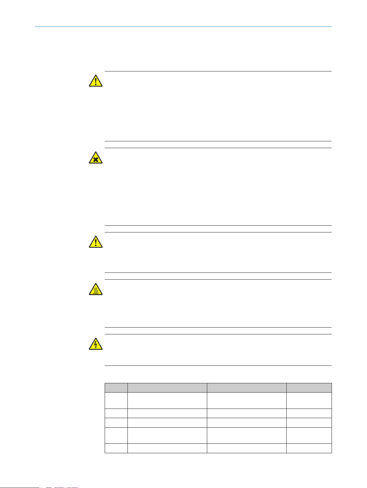
1.3.1 Warning symbols
Symbol Significance
Hazard (general)
Hazard by voltage
8023849/14SF/V1-1/2019-07 | SICK O P ER A TI N G I NS T RU C TI O NS | SFU
Subject to change without notice
5
Page 6
1 ABOUT THIS DOCUMENT
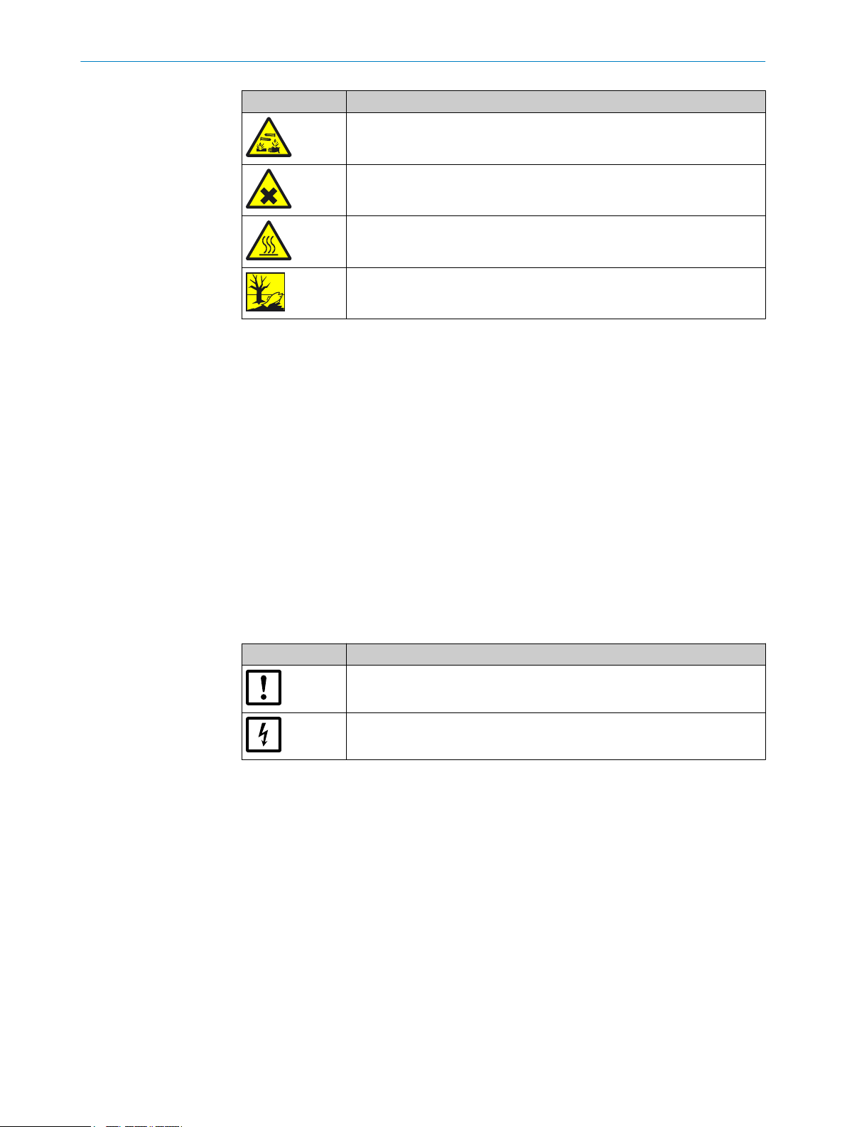
Symbol Significance
1.3.2 Warning levels / signal words
DANGER
Risk or hazardous situation which will result in severe personal injury or death.
WARNING
Risk or hazardous situation which could result in severe personal injury or death.
Hazard by acidic substances
Hazards by noxious substances
Hazard by high temperature
Hazard for the environment/nature/organic life
CAUTION
Hazard or unsafe practice which could result in less severe or minor injuries.
Notice
Hazard which could result in property damage.
Note
Hints.
1.3.3 Information symbols
Symbol Significance
Important technical information for this product
Important information on electric or electronic functions
6
O PE R AT I NG IN S TR U CT I ON S | SFU 8023849/14SF/V1-1/2019-07 | SICK
Subject to change without notice
Page 7
2 Safety information
2.1 Basic safety information
WARNING
Health risk through dangerous sample gas
If dangerous sample gas is applied to the SFU:
The operator is responsible for safe handling of sample gas.
b
WARNING
Risk of explosion in potentially explosive atmospheres
Do not operate the SFU in potentially explosive atmospheres.
b
WARNING
Hazard through explosive or ignitable gases
Do not use the SFU for measuring explosive or combustible gases.
b
SAFETY INFORMATION 2
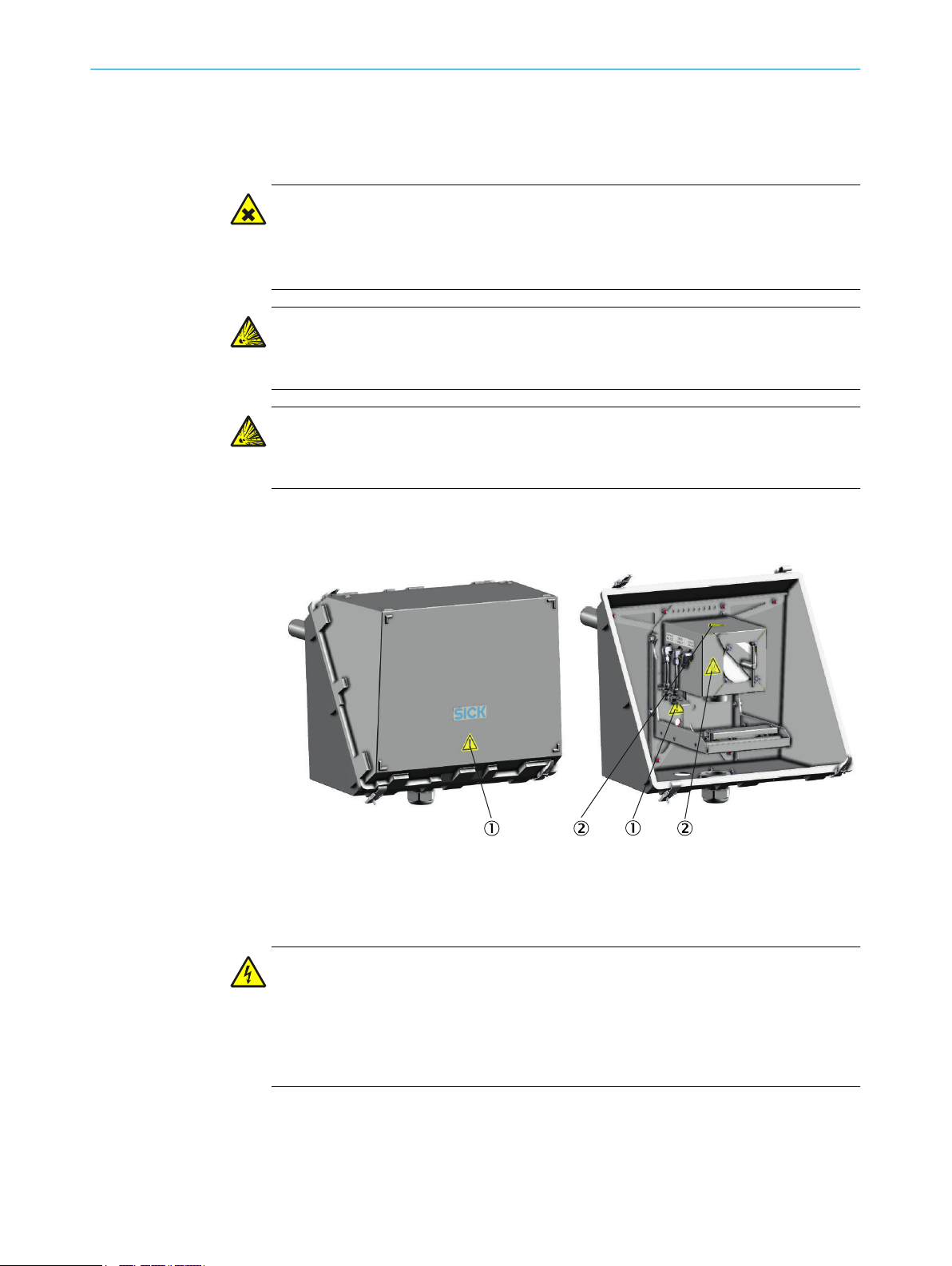
2.2 Warnings on the device
Figure 1: Location of the warning signs on the device
Warning sign "Caution!"
1
Warning sign "Hot surface!"
2
DANGER
Hazard by voltage
Only authorized electricians may perform work on electrical components.
b
Do not touch live components.
b
Disconnect the device from the power supply before working on electrical compo‐
b
nents (e.g. by switching off the measuring system).
8023849/14SF/V1-1/2019-07 | SICK O P ER A TI N G I NS T RU C TI O NS | SFU
Subject to change without notice
7
Page 8

2 SAFETY INFORMATION
WARNING
Risk of burns on hot surfaces
Avoid contact with hot surfaces or wear protective clothing (e.g. protective gloves).
b
Lay hot parts on fireproof supports only.
b
2.3 Intended use
The gas sampling unit is used for extracting a partial stream of a gas mixture (usually
flue gas) from a line, stack or similar and for retaining particles that are contained in
the gas stream.
2.4 Qualification of the operator
The SFU may only be maintained by persons properly instructed on the tasks assigned,
possible risks and protective measures.
8
O PE R AT I NG IN S TR U CT I ON S | SFU 8023849/14SF/V1-1/2019-07 | SICK
Subject to change without notice
Page 9
3 Product description
3.1 Product identification
Product name SFU-BF NI GL
Accessories:
Name of the pre-assembled set:
Consisting of:
Manufacturer SICK AG
Type plate The type plate is located on the underside of the gas sam‐
PRODUCT DESCRIPTION 3
The exact type designation can be found on the type plate.
0.5 m unheated maritime gas sampling tube
•
0.8 m unheated maritime gas sampling tube
•
0.5 m heated gas sampling tube
•
0.8 m heated gas sampling tube
•
1.0 m heated gas sampling tube
•
1.5 m heated gas sampling tube
•
2.0 m heated gas sampling tube
•
IP54 enclosure
•
Can already be ordered pre-assembled in combination
with the maritime gas sampling unit SFU-BF NI GL
SFU-BF NI GL in IP54 enclosure (PN 2098126)
SFU-BF NI GL
•
IP54 enclosure for SFU
•
Erwin-Sick-Str. 1 · D-79183 Waldkirch · Germany
pling unit.
NOTICE
It is possible that your SFU has a different configuration to that described in this Man‐
ual.
Refer to the System Documentation delivered with your SFU for the individual con‐
•
figuration of your system.
8023849/14SF/V1-1/2019-07 | SICK O P ER A TI N G I NS T RU C TI O NS | SFU
Subject to change without notice
9
Page 10
3 PRODUCT DESCRIPTION
3.2 Product description
Figure 2: Example configuration of a set consisting of weatherproof enclosure and SFU
Weatherproof enclosure
1
Gas sampling tube
2
SFU filter housing
3
Flange
4
Silicone press ring seal (gas sampling tube seal)
5
The gas sampling unit consists of filter housing, gas sampling tube, weatherproof enclo‐
sure and optional pre-filter.
Application area
The gas sampling unit SFU is used for flue gas extraction and filtering for analysis in a
measuring system.
The flue gas is taken via a gas sampling tube and fed to a measuring system after filtra‐
tion.
The gas sampling tube is optionally available in various lengths.
As an option, the gas sampling tube contains a pre-filter at the probe tip.
For maritime applications, unheated gas sampling tubes without pre-filters are used.
Measuring system
The gas sampling unit is operated on a SICK measuring system. Thus, only this operat‐
ing mode is described in this Manual.
Applications with customer-owned peripheral devices are not planned.
10
O PE R AT I NG IN S TR U CT I ON S | SFU 8023849/14SF/V1-1/2019-07 | SICK
Subject to change without notice
Page 11
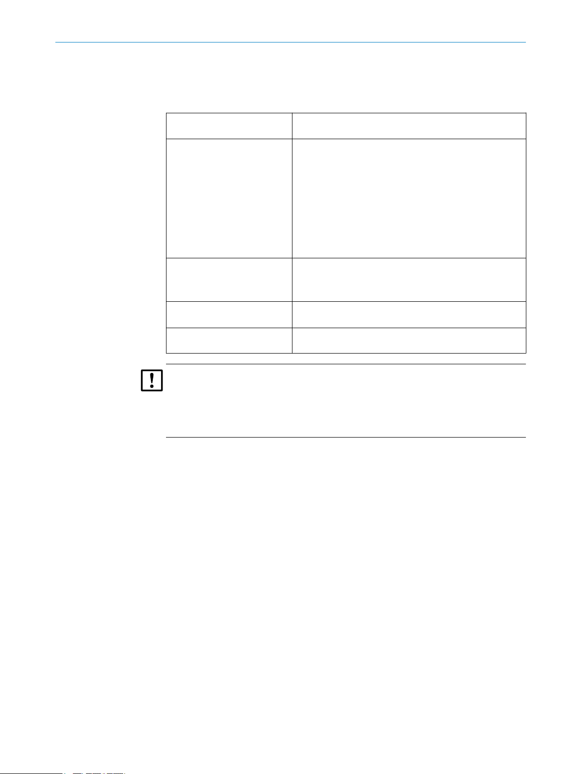
3.3 Design
Figure 3: SFU-BF NI GL
Gas sampling tube
1
Filter housing
2
3 pneumatic lines (backflush, activa‐
3
tion of main valve, zero gas)
Output sample gas line
4
Input connection bundle (electrical
5
and pneumatic lines)
Filter element with rotary handle
6
PRODUCT DESCRIPTION 3
The gas sampling unit consists of the following subassemblies:
•
•
The electrically heated filter housing is made of coated aluminum. The filter housing is
insulated by an aluminum housing lined with polyimide.
The weatherproof enclosure is made of glass fiber reinforced plastic (GRP).
Thermostatic control
The gas sampling unit is thermostatically controlled.
•
•
3.3.1 Gas sampling tube
The length of the gas sampling tube depends on the conditions at the sampling point.
The gas sampling tube is available for maritime applications in an unheated version.
Type and length of the gas sampling tube are described in the supplied system docu‐
mentation.
Gas sampling tube:
Heated gas sampling tube:
°
Unheated maritime gas sampling tube
°
Optional: Pre-filter at the tip of the gas sampling tube
°
SFU in IP54 enclosure:
Heated filter housing with filter element
°
Weatherproof enclosure
°
Heating control with Pt100 sensor and external heating control
Limit value monitoring in the controller of the measuring system
NOTE
The gas sampling tube is supplied pre-assembled.
8023849/14SF/V1-1/2019-07 | SICK O P ER A TI N G I NS T RU C TI O NS | SFU
Subject to change without notice
11
Page 12
4 INSTALLATION AND START-UP
4 Installation and start-up
4.1 Important information
WARNING
Risk of injury by a heavy load
The weatherproof enclosure including the sampling system with flange weighs
approx. 30 kg.
Use proper lifting techniques to lift or move the device.
b
Lift the unit by the enclosure. If necessary, remove the cover in order to grip the
b
device better and reduce the weight.
Always work in pairs.
b
WARNING
Health risk through dangerous sample gas
If dangerous sample gas is applied to the SFU: The operator is responsible for safe han‐
dling of sample gas.
In addition to these Operating Instructions, observe all local laws, technical rules,
b
and company-internal instructions valid at the site where the SFU is installed.
Operate the SFU only in rooms with adequate installation OR install suitable gas
b
monitoring equipment.
Channel sample gas off safely.
b
WARNING
Hazard through sample gas pressure
The stacks can have underpressure or overpressure.
Observe information from the plant operator.
b
WARNING
Risk of burns on hot surfaces
Filter housing, flanges and sample gas line can be hot.
Allow the surface of the device parts to cool down to body temperature or wear
b
suitable protective gloves.
WARNING
Danger to life by electric voltage
Only allow an authorized electrician to work on the electric system.
b
The assembly of the gas sampling unit contains the following work steps:
Step Work step Special features Side
1 Install the welding neck flange Has to be performed by the
operator beforehand
2 Connect the sample gas line page 17
3 Connect the hoses for valves page 18
4 Connect the electrical connec‐
tions
5 Install the gas sampling tube page 20
page 15
page 19
12
O PE R AT I NG IN S TR U CT I ON S | SFU 8023849/14SF/V1-1/2019-07 | SICK
Subject to change without notice
Page 13

Step Work step Special features Side
6 Attach the SFU to the welding
neck flange
4.2 Weatherproof enclosure
INSTALLATION AND START-UP 4
Observe preheating period page 20
Figure 4: SFU-BF NI GL in weatherproof enclosure (closed left and open right)
Enclosure cover
1
Enclosure base
2
Tension locks
3
Filter housing
4
Gas sampling tube
5
Ventilation membrane
6
DANGER
Hazard by voltage
Live parts are accessible after the weatherproof enclosure has been opened.
Disconnect the gas sampling unit from the power supply before opening the enclo‐
b
sure (for example by switching off the measuring system).
CAUTION
Risk of burns on hot surfaces
You can perform the work while the filter is hot.
Wear suitable gloves.
b
Removing the enclosure cover
1 Unlock the tension locks.
2 Pull the enclosure cover away from the gas sampling tube and lift.
Fitting the enclosure cover
1 Fit the enclosure cover in the direction of the gas sampling tube.
2 Lock the tension locks.
8023849/14SF/V1-1/2019-07 | SICK O P ER A TI N G I NS T RU C TI O NS | SFU
Subject to change without notice
13
Page 14

4 INSTALLATION AND START-UP
4.3 Preparing the connection bundle
Figure 5: Standard connection bundle
Standard hose bundle cable (systemspecific example) with:
- Power supply
- Grounding conductor yellow/green
- Signal lines
- Tube, gray: Zero gas/span gas
- Tube, black: Main valve
- Tube, blue: Backflush
14
Figure 6: DNV GL approved connection bundle:
DNV GL approved connection bundle:
- Power supply
- Grounding conductor yellow/green
- Signal lines
- Tube, gray: Zero gas/span gas
- Tube, black: Main valve
- Tube, blue: Backflush
Halogen-reduced for use on passenger
ships
Additionally improved protection against
fire
The connection bundle (option) connects the SFU with the measuring system.
O PE R AT I NG IN S TR U CT I ON S | SFU 8023849/14SF/V1-1/2019-07 | SICK
Subject to change without notice
Page 15

Preparation of the connection bundle
NOTE
Leave a sufficient length for pulling the gas sampling unit out of the stack (approx. 2
m).
1 Strip the connection bundle and shorten the hoses and lines to the required
length.
Cut the hoses at right angles. Avoid damaging the lines and hose lines.
2 Cut the flexible wires to the required length. Press the crimp lead end sleeves onto
the ends of the flexible wires.
4.4 Mounting
4.4.1 Installing the welding neck flange
WARNING
Risk of burns by hot flanges.
The flanges can reach high temperatures.
Before starting any work on the flanges, allow the flanges to cool down to body
b
temperature or wear appropriate protective gloves.
INSTALLATION AND START-UP 4
DANGER
Health risk through hot or toxic gases/dusts in the measuring duct
The measuring duct can contain hot or toxic gases or dust deposits which can escape
when opening the duct-side flange. Even if the measuring duct is out of operation dur‐
ing the installation, escaping gases can lead to severe damage to health.
Always put the measuring duct out of operation for the duration of the installation.
b
If required, purge the measuring duct with ambient air before starting installation
b
work.
During installation work, always wear protective clothing which is suitable or speci‐
b
fied by the operating company.
The operator is responsible for installing the welding neck flange.
The specifications of the flange connection are described in the System Documentation
delivered.
8023849/14SF/V1-1/2019-07 | SICK O P ER A TI N G I NS T RU C TI O NS | SFU
Subject to change without notice
15
Page 16

min.70
10°
~
~30
1
2
3 4
a
4 INSTALLATION AND START-UP
Figure 7: Installation requirements for welding neck flange
Gas sampling tube
1
Stack wall
2
Welding neck flange
3
Probe filter
4
Attach the flange with a tilt of approx. 10°.
b
The minimum distance a behind welding neck flange must be min. the length
b
specified in the following table in order to maintain and dismantle the gas sam‐
pling unit.
Table 1: Minimum distance behind welding neck flange
Length of gas sampling tube Minimum distance a
0.5 m 915 mm
0.8 m 1215 mm
1.0 m 1415 mm
1.5 m 1915 mm
2.0 m 2415 mm
16
O PE R AT I NG IN S TR U CT I ON S | SFU 8023849/14SF/V1-1/2019-07 | SICK
Subject to change without notice
Page 17

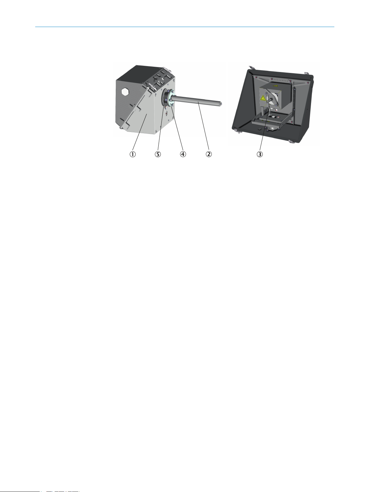
4.4.2 Connection of sample gas line
Figure 8: Sample gas connection SFU-BF NI
GL in weatherproof enclosure
Insulating shell
1
Clamping ring screw connection
2
Sample gas line
3
Cable gland with cap nut, small
4
Cable gland with cap nut, large
5
INSTALLATION AND START-UP 4
NOTE
If you lay the heated sample gas line before installing the gas sampling unit: Observe
the installation of the sample gas line:
Start laying at the measuring system:
b
The end with electrical connection is connected to the measuring system.
°
The end without electrical connection is connected to the gas sampling unit.
°
Roll up excess length at the gas sampling unit.
Leave enough length for pulling out the gas sampling unit (approx. 2 m).
Protect the line from damage (chafing through vibration, mechanical and thermal
b
load).
Observe a minimum bending radius of 300 mm.
b
1. Remove the enclosure cover (see "Weatherproof enclosure", page 13).
2. Unscrew the large cap nut and slide it onto the sample gas line.
3. Unscrew the insulation half-shell.
4. Feed the sample gas line through the large cable gland of the weatherproof enclo‐
sure and then through the installation plate and the hose clamp.
5. Screw the sample gas line tight on the clamping ring screw connection.
For first screwing (clamping ring still loose): 1¼ turn to "hand-tight".
°
For further screwing: (clamping ring tight) ¼ turn to "hand-tight".
°
6. Fasten the sample gas line using a hose clamp. The screw head can be reached
via an opening in the chamfer of the installation plate.
7. Screw the insulation half-shell back on again.
8. Tighten the cap nut hand-tight.
9. Check hose connections for leaks:
The leak tightness check is performed via the connected measuring system: See
the Operating Instructions of the measuring system.
8023849/14SF/V1-1/2019-07 | SICK O P ER A TI N G I NS T RU C TI O NS | SFU
Subject to change without notice
17
Page 18

4 INSTALLATION AND START-UP
4.4.3 Connection of the pneumatic lines
NOTICE
Risk of damaging the measuring system.
Ensure correct assignment of the pneumatic connections.
•
Ensure leak tightness of the system.
•
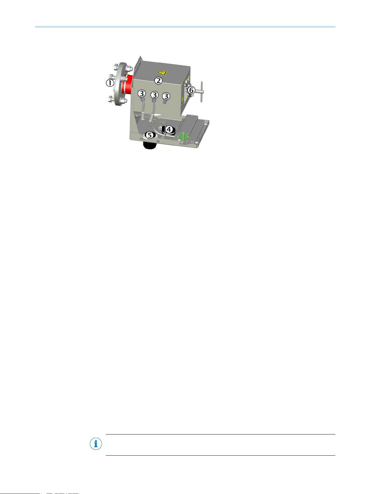
Connection for SFU-BF NI GL
Figure 9: Connection of SFU-BF NI GL pneu‐
matic lines
Backflush
1
Main valve
2
Zero gas
3
Installation plate
4
1. Push the cap nut onto the connection bundle.
2. Feed the connection bundle through the cable gland of the weatherproof enclo‐
sure and then through the installation plate.
3. Connect the 3 hoses with the 3 hose fittings on the filter housing and ensure cor‐
rect layout.
4. Push the hoses flush over the hose connections of the hose fitting.
5. Hose for the zero gas: Use clamping ring screw connection with support sleeve.
6. Tighten the cap nut by hand.
7. Screw the cable gland tight.
4.4.3.1 Adapter for inch thread (option)
If you want to connect pneumatic lines with inch thread: There is an adapter set with 4
clamping ring screw fittings.
Part No. "Adapter set inch thread": 2083838
18
O PE R AT I NG IN S TR U CT I ON S | SFU 8023849/14SF/V1-1/2019-07 | SICK
Subject to change without notice
Page 19

INSTALLATION AND START-UP 4
Figure 10: Adapter set
Installation
1. Wrap the thread with 2 - 2.5 layers of Teflon tape.
2. Tighten the adapter with an open-end wrench until a distinct increase in strength
is felt.
Then tighten by approx. 1/8 to 1/4 turn.
4.5 Electrical installation
WARNING
Danger to life by electric voltage
Only allow an authorized electrician to work on the electric system.
b
WARNING
Risk of short-circuit due to condensate.
Allow the electronics to acclimatize sufficiently before connecting.
b
8023849/14SF/V1-1/2019-07 | SICK O P ER A TI N G I NS T RU C TI O NS | SFU
Subject to change without notice
19
Page 20

4 INSTALLATION AND START-UP
Figure 11: Terminal diagram for 230 V and 115 V
The electrical connection of the gas sampling unit is made via the connection terminals
on the installation plate.
Observe the terminal diagram on the SFU.
The temperature sensors and the heating cartridges are wired ex factory.
Remove the enclosure.
b
Perform electrical connections.
b
4.6
Installing the gas sampling tube on the gas sampling unit
Installing the gas sampling tube
The gas sampling unit with gas sampling tube is supplied pre-assembled.
Installing the pre-filter
The pre-filter can be screwed to the gas sampling tube.
1 Wrap the thread with Teflon tape.
2 Screw the pre-filter onto the tip of the gas sampling tube. Tighten by hand with a
wrench.
4.7 Installing the SFU on the welding neck flange
NOTICE
Risk of contamination of the gas sampling unit
Do not install a cold gas sampling unit on the stack.
Allow the gas sampling unit to warm up before installing it on the welding neck
b
flange.
Warm-up time: Approx. 1.5 h at 25 °C ambient temperature
b
20
O PE R AT I NG IN S TR U CT I ON S | SFU 8023849/14SF/V1-1/2019-07 | SICK
Subject to change without notice
Page 21

1
2
3
4
INSTALLATION AND START-UP 4
Figure 12: Installation of gas sampling tube on welding neck flange
Gas sampling tube
1
Welding neck flange
2
Filter housing flange
3
Filter housing
4
WARNING
Risk of burns on hot surfaces
The gas sampling tube and the gas sampling unit become hot during operation.
Wear suitable protective clothing, e.g. heat-resistant gloves.
b
1. Push the seal over the gas sampling tube.
2. Push the gas sampling unit with probe tube into the welding neck flange.
The hose outputs of the gas sampling unit have to point downwards.
3. Screw the filter housing flange of the gas sampling unit to the welding neck flange.
4. Fit the weatherproof enclosure: see "Weatherproof enclosure", page 13
8023849/14SF/V1-1/2019-07 | SICK O P ER A TI N G I NS T RU C TI O NS | SFU
Subject to change without notice
21
Page 22

5 MAINTENANCE
5 Maintenance
5.1 Important Information
WARNING
Risk of injury by a heavy load
The weatherproof enclosure including the sampling system with flange weighs
approx. 30 kg.
Use proper lifting techniques to lift or move the device.
b
Lift the unit by the enclosure. If necessary, remove the cover in order to grip the
b
device better and reduce the weight.
Always work in pairs.
b
WARNING
Health risk through dangerous sample gas
If dangerous sample gas is applied to the SFU: The operator is responsible for safe han‐
dling of sample gas.
In addition to these Operating Instructions, observe all local laws, technical rules,
b
and company-internal instructions valid at the site where the SFU is installed.
Operate the SFU only in rooms with adequate installation OR install suitable gas
b
monitoring equipment.
Channel sample gas off safely.
b
WARNING
Hazard through sample gas pressure
The stacks can have underpressure or overpressure.
Observe information from the plant operator.
b
WARNING
Risk of burns on hot surfaces
Filter housing, flanges and sample gas line can be hot.
Allow the surface of the device parts to cool down to body temperature or wear
b
suitable protective gloves.
WARNING
Danger to life by electric voltage
Only allow an authorized electrician to work on the electric system.
b
5.2 Maintenance plan
No. Maintenance work Reference Interval
W1
W2
W3 Check gas connections
1
3M = every 3 months
Replace sintered metal filter element
and seals
Replace glass fiber filter element
and seals
see "Replacing the sintered metal
filter element", page 23
see "Replacing the glass fiber filter
element", page 26
see "Checking for correct operation",
page 32
3M
3M
3M
1
1
1
22
O PE R AT I NG IN S TR U CT I ON S | SFU 8023849/14SF/V1-1/2019-07 | SICK
Subject to change without notice
Page 23

5.3 Spare parts
MAINTENANCE 5
No. Conversion Reference Interval
U1 Change from sintered metal to glass
fiber filter element
Required spare parts for W1 and W2 Part number Quantity required Picture
Service kit (contains: 1*2 μm sin‐
tered metal filter element, 2*flat
seals, 1*O-ring)
2039002 1
see "Retrofitting the filter element",
page 29
-
Service kit (contains 1*0.1µm glass
fiber filter element, 1*flat seal, 1*Oring)
Required spare parts for U1 Part number Quantity required Picture
Glass fiber filter element with holder
(contains 1*0.1µm glass fiber filter
element, adapter, 1*flat seal, 1*Oring
2043616 1
2024972 1
NOTE
Further spare parts can be found in the individual System Description provided with the
gas sampling unit.
5.4 Replacing the sintered metal filter element
You can perform the work while the filter element is hot.
Pay attention to the warning about hot surfaces.
The filter element may be hot inside.
WARNING
Risk of burns on hot surfaces
The filter element can reach high temperatures in operation.
Wear suitable gloves.
b
Provide a heat-resistant support.
b
WARNING
Hazard by toxic substances
Filter elements can contain toxic substances depending on the sample gas composi‐
tion.
Observe the relevant safety regulations.
b
Dispose of the filter elements in an environmentally compatible manner.
b
8023849/14SF/V1-1/2019-07 | SICK O P ER A TI N G I NS T RU C TI O NS | SFU
Subject to change without notice
23
Page 24

MAINTENANCE
5
Procedure
1. Switch off the fuse of the gas sampling unit in the measuring system.
The position of the fuse is described in the System Documentation enclosed with
the measuring system.
2. Remove the enclosure:see "Weatherproof enclosure", page 13.
3. Check all gas connections:
Optical condition
°
Tight seat
°
Leak tightness:
°
The leak tightness check is performed via the connected measuring system:
See the Operating Instructions of the measuring system.
Changing the sintered metal filter element
1. Loosen the rotary handle counterclockwise.
Rotary handle
1
Mounting bracket
2
Pressure disk (covered)
3
2. Swing the mounting bracket to the right.
WARNING
Risk of burns on hot surfaces
The inner parts of the gas sampling filter can be especially hot.
Wear suitable gloves.
b
Provide a heat-resistant support.
b
CAUTION
Risk of injury due to high weight
Do not drop the filter cover.
b
3. Pull the filter cover out using the rotary handle.
4. If the filter cover is hot: Place the filter cover on a heat-resistant mat.
5. Remove the sintered metal filter element.
24
O PE R AT I NG IN S TR U CT I ON S | SFU 8023849/14SF/V1-1/2019-07 | SICK
Subject to change without notice
Page 25

Sintered metal filter element
1
Filter housing
2
6. Pull out the bottom flat seal with a hook.
7. Insert new bottom flat seal.
MAINTENANCE 5
Bottom flat seal
1
8. Replace O-ring and flat seal of the filter cover.
O-ring
1
Flat seal
2
9. Insert new or cleaned filter element.
If one side of the filter element has a groove: The groove must point in the direc‐
tion of the filter cover.
8023849/14SF/V1-1/2019-07 | SICK O P ER A TI N G I NS T RU C TI O NS | SFU
Subject to change without notice
25
Page 26

5 MAINTENANCE
10. Fit the filter cover.
11. Swing back the mounting bracket. Make sure that the pressure disk is behind the
mounting bracket.
Rotary handle
1
Pressure disk
2
Mounting bracket
3
12. Tighten the rotary handle clockwise.
13. Fit the enclosure again: see "Weatherproof enclosure", page 13.
5.5 Replacing the glass fiber filter element
You can perform the work while the filter element is hot.
Pay attention to the warning about hot surfaces.
The filter can have an internal temperature of 185 °C.
WARNING
Risk of burns on hot surfaces
The filter element can reach high temperatures in operation.
Wear suitable gloves.
b
Provide a heat-resistant support.
b
WARNING
Hazard by toxic substances
Filter elements can contain toxic substances depending on the sample gas composi‐
tion.
Observe the relevant safety regulations.
b
Dispose of the filter elements in an environmentally compatible manner.
b
Replacing fine filter cartridge
1. Loosen the rotary handle counterclockwise.
26
O PE R AT I NG IN S TR U CT I ON S | SFU 8023849/14SF/V1-1/2019-07 | SICK
Subject to change without notice
Page 27

Rotary handle
1
Mounting bracket
2
Pressure disk (covered)
3
2. Swing the mounting bracket to the right.
MAINTENANCE
5
WARNING
Risk of burns on hot surfaces
The filter element can reach high temperatures in operation.
Wear suitable gloves.
b
Provide a heat-resistant support.
b
CAUTION
Risk of injury due to high weight
Do not drop the filter cover.
b
Filter housing
1
Filter cover
2
Mounting bracket
3
Pressure disk
4
3. Pull out the filter cover with glass fiber filter element using the rotary handle.
4. If the filter cover is hot: Place the filter cover on a heat-resistant mat.
5. Pull out the bottom flat seal with a hook.
8023849/14SF/V1-1/2019-07 | SICK O P ER A TI N G I NS T RU C TI O NS | SFU
Subject to change without notice
27
Page 28

MAINTENANCE
5
Bottom flat seal
1
6. Loosen the glass fiber filter element from the filter handle by opening the spiral
thread.
O-ring
1
Glass fiber filter element
2
Rotary handle
3
7. Insert new bottom flat seal.
8. Renew the O-ring in the filter cover.
9. Fit new or cleaned glass fiber filter element on the filter cover. Tighten the spiral
thread.
If one side of the filter element has a groove: The groove must point in the direc‐
tion of the filter cover.
10. Replace the filter cover.
Rotary handle
1
Pressure disk
2
Mounting bracket
3
28
11. Swing back the mounting bracket. Make sure that the pressure disk is behind the
mounting bracket.
O PE R AT I NG IN S TR U CT I ON S | SFU 8023849/14SF/V1-1/2019-07 | SICK
Subject to change without notice
Page 29

12. Tighten the rotary handle clockwise.
13. Fit the housing again: see "Weatherproof enclosure", page 13.
5.6 Retrofitting the filter element
You can perform the work while the filter element is hot.
Pay attention to the warning about hot surfaces.
The filter can have an internal temperature of 185 °C.
WARNING
Risk of burns on hot surfaces
The filter element can reach high temperatures in operation.
Wear suitable gloves.
b
Provide a heat-resistant support.
b
WARNING
Hazard by toxic substances
Filter elements can contain toxic substances depending on the sample gas composi‐
tion.
MAINTENANCE 5
Observe the relevant safety regulations.
b
Dispose of the filter elements in an environmentally compatible manner.
b
Procedure
1. Switch off the fuse of the gas sampling unit in the measuring system.
The position of the fuse is described in the System Documentation enclosed with
the measuring system.
2. Remove the enclosure:see "Weatherproof enclosure", page 13.
3. Check all gas connections:
Optical condition
°
Tight seat
°
Leak tightness:
°
The leak tightness check is performed via the connected measuring system:
See the Operating Instructions of the measuring system.
Retrofitting the sintered metal filter element to a glass fiber filter element
1. Loosen the rotary handle counterclockwise.
8023849/14SF/V1-1/2019-07 | SICK O P ER A TI N G I NS T RU C TI O NS | SFU
Subject to change without notice
29
Page 30

MAINTENANCE
5
Rotary handle
1
Mounting bracket
2
Pressure disk (covered)
3
2. Swing the mounting bracket to the right.
WARNING
Risk of burns on hot surfaces
The filter element can reach high temperatures in operation.
Wear suitable gloves.
b
Provide a heat-resistant support.
b
CAUTION
Risk of injury due to high weight
Do not drop the filter cover.
b
3. Pull the filter cover out using the rotary handle.
4. If the filter cover is hot: Place the filter cover on a heat-resistant mat.
5. Remove the sintered metal filter element.
30
Sintered metal filter element
1
Filter housing
2
6. Pull out the bottom flat seal with a hook.
7. Insert new bottom flat seal.
O PE R AT I NG IN S TR U CT I ON S | SFU 8023849/14SF/V1-1/2019-07 | SICK
Subject to change without notice
Page 31

Bottom flat seal
1
8. Replace O-ring and flat seal of the filter cover.
MAINTENANCE
5
O-ring
1
Position of flat seal
2
9. Fit the glass fiber filter element on the filter cover. Tighten with the spiral thread.
If one side of the glass fiber filter element has a groove: The groove must point in
the direction of the filter cover.
O-ring
1
Glass fiber filter element
2
Rotary handle
3
10. Replace the filter cover.
11. Swing back the mounting bracket. Make sure that the pressure disk is behind the
mounting bracket.
8023849/14SF/V1-1/2019-07 | SICK O P ER A TI N G I NS T RU C TI O NS | SFU
Subject to change without notice
31
Page 32

5 MAINTENANCE
Rotary handle
1
Pressure disk
2
Mounting bracket
3
12. Tighten the rotary handle clockwise.
13. Fit the enclosure again: see "Weatherproof enclosure", page 13
5.7 Checking for correct operation
Check all fastening screws of the housing for tight seat.
•
Check the sample gas line for damage.
•
Check all hose fittings for tight seat.
•
Check gas sampling unit for cleanness, dryness and freedom from corrosion.
•
Check all electric connections for freedom from corrosion and tight seat.
•
Check grounding conductors are free from corrosion.
•
Perform a leak tightness check:
•
The leak tightness check is performed via the connected measuring system: See
the Operating Instructions of the measuring system.
32
O PE R AT I NG IN S TR U CT I ON S | SFU 8023849/14SF/V1-1/2019-07 | SICK
Subject to change without notice
Page 33

6 Troubleshooting
6.1 Troubleshooting
Fault Possible cause Correction
Gas throughput decreases Pre-filter contaminated Clean or replace
Heating failed Heating cartridge or tempera‐
Contaminated or corroded gas
paths
Leaky non-return valves Contaminated instrument air Replace
Leaky main valve Valve seating contaminated or
TROUBLESHOOTING 6
Filter element contaminated
If necessary, replace seal or
ture sensor defective
Defective seal Replace seal
Defective or missing pre-filter Replace
damaged
Metal bellow leaky Replace the metal bellow
defective component
Check the purity of the instru‐
ment air
Replace the valve cone
Replace the filter housing
8023849/14SF/V1-1/2019-07 | SICK O P ER A TI N G I NS T RU C TI O NS | SFU
Subject to change without notice
33
Page 34

7 DISPOSAL
7 Disposal
The device can easily be disassembled into its components which can then be sent to
the respective raw material recycling facilities.
WARNING
Filters and lines with sample gas contact can contain toxic substances.
Observe the relevant safety regulations.
Depending on their components, filters and lines with sample gas contact must be
b
disposed of according to the legal regulations. If required, they must be treated as
hazardous waste.
34
O PE R AT I NG IN S TR U CT I ON S | SFU 8023849/14SF/V1-1/2019-07 | SICK
Subject to change without notice
Page 35

8 Technical data
8.1 Compliances and Standards
Compliance
The technical version of device SFU-BF NI GL complies with the following EU directives
and EN standards:
EC Directive: LVD (Low Voltage Directive)
•
EN 61010-1: Safety requirements for electrical equipment for measurement, con‐
trol and laboratory use
Further standards: See Declaration of Conformity provided with the device
Additional standards for SFU-BF NI GL
MARPOL Annex VI and NTC 2008 - MEPC.177(58)
•
Guidelines for exhaust gas cleaning systems - MEPC.184(59)
•
DNV GL Rules for Classification and Construction, Part VI Additional Rules and
•
Guidelines Chapter 7, Guidelines for the Performance of Type Approvals, Test
Requirements for Electrical / Electronic Equipment and Systems (2012)
TECHNICAL DATA 8
8.2 Dimensions
Figure 13: SFU-BF NI GL in weatherproof enclosure
8.3 Operating data
Ambient conditions SFU-BF NI GL in weatherproof enclosure
Ambient temperature -35 … +55 °C (-31 ... +131 °F)
Storage temperature –40 … +60 °C (-40 ... 140 °F)
Relative humidity Max. 95%
Degree of protection IP54
Installation SFU-BF NI GL in weatherproof enclosure
Tubing SFU-BF NI GL
Main valve
•
Zero gas
•
Backflush
•
Sample gas line
•
8023849/14SF/V1-1/2019-07 | SICK O P ER A TI N G I NS T RU C TI O NS | SFU
Subject to change without notice
Dimensions:
8 mm
•
6 mm
•
8 mm
•
6 mm
•
35
Page 36

8 TECHNICAL DATA
Installation SFU-BF NI GL in weatherproof enclosure
Compressed air
Main valve
•
Zero gas
•
Backflush
•
Flange
NW = Rated width
ND = Rated pressure
Fitting position Horizontally with an inclination of approx. 10° (see "Installing
Power input SFU-BF NI GL in weatherproof enclosure
probe filter 115/230 V, 50-60 Hz, max. 450 VA
Device characteristics SFU-BF NI GL in weatherproof enclosure
Materials
Gas sampling tube
•
IP54 enclosure
•
Locks
•
Seals
•
Weight Approx. 30 kg (SFU in IP54 enclosure with flange and gas
Gas temperature in sampling
system
Gas temperature in stack Unheated gas sampling tube: Max. 1300°C (2400°F)
Heating temperature of the SFU Max. 200°C (392°F)
Temperature control External, Pt100
Limit monitoring External heating controller
Purge gas flow Approx.12 l/min
Backpurge flow rate Approx.80 l/min
Sample gas throughput 300 ... 1000 l/h
Heating up time Approx. 1,5 h (from room temperature to 200 °C)
Pressure:
5 - 6 bar (500 - 600 kPascal)
•
2.5 - 3 bar (250 - 300 kPascal)
•
5 - 6 bar (500 - 600 kPascal)
•
NW 65 ND 6
the welding neck flange", page 15)
Materials
Application-dependent;maritime unheated gas sampling
•
tubes: 1.4547/254 SMO
GRP enclosure (glass fiber reinforced plastic)
•
Tension locks:Stainless steel
•
EPDM/silicone
•
sampling tube)
Max. 250°C (482°F)
Heated gas sampling tube: Max. 200°C (392°F)
36
Standard lengths of unheated maritime gas sampling tubes [mm]; Material 1.4547/254 SMO
500 800
Standard lengths of heated gas sampling tubes [mm]; Material 1.4404
500 800 1000 1500 2000
O PE R AT I NG IN S TR U CT I ON S | SFU 8023849/14SF/V1-1/2019-07 | SICK
Subject to change without notice
Page 37

TECHNICAL DATA 8
8023849/14SF/V1-1/2019-07 | SICK O P ER A TI N G I NS T RU C TI O NS | SFU
Subject to change without notice
37
Page 38

Detailed addresses and further locations at www.sick.com
Australia
Phone +61 (3) 9457 0600
1800 33 48 02 – tollfree
E-Mail sales@sick.com.au
Austria
Phone +43 (0) 2236 62288-0
E-Mail office@sick.at
Belgium/Luxembourg
Phone +32 (0) 2 466 55 66
E-Mail info@sick.be
Brazil
Phone +55 11 3215-4900
E-Mail comercial@sick.com.br
Canada
Phone +1 905.771.1444
E-Mail cs.canada@sick.com
Czech Republic
Phone +420 234 719 500
E-Mail sick@sick.cz
Chile
Phone +56 (2) 2274 7430
E-Mail chile@sick.com
China
Phone +86 20 2882 3600
E-Mail info.china@sick.net.cn
Denmark
Phone +45 45 82 64 00
E-Mail sick@sick.dk
Finland
Phone +358-9-25 15 800
E-Mail sick@sick.fi
France
Phone +33 1 64 62 35 00
E-Mail info@sick.fr
Germany
Phone +49 (0) 2 11 53 010
E-Mail info@sick.de
Greece
Phone +30 210 6825100
E-Mail office@sick.com.gr
Hong Kong
Phone +852 2153 6300
E-Mail ghk@sick.com.hk
Hungary
Phone +36 1 371 2680
E-Mail ertekesites@sick.hu
India
Phone +91-22-6119 8900
E-Mail info@sick-india.com
Israel
Phone +972 97110 11
E-Mail info@sick-sensors.com
Italy
Phone +39 02 27 43 41
E-Mail info@sick.it
Japan
Phone +81 3 5309 2112
E-Mail support@sick.jp
Malaysia
Phone +603-8080 7425
E-Mail enquiry.my@sick.com
Mexico
Phone +52 (472) 748 9451
E-Mail mexico@sick.com
Netherlands
Phone +31 (0) 30 229 25 44
E-Mail info@sick.nl
New Zealand
Phone +64 9 415 0459
0800 222 278 – tollfree
E-Mail sales@sick.co.nz
Norway
Phone +47 67 81 50 00
E-Mail sick@sick.no
Poland
Phone +48 22 539 41 00
E-Mail info@sick.pl
Romania
Phone +40 356-17 11 20
E-Mail office@sick.ro
Russia
Phone +7 495 283 09 90
E-Mail info@sick.ru
Singapore
Phone +65 6744 3732
E-Mail sales.gsg@sick.com
Slovakia
Phone +421 482 901 201
E-Mail mail@sick-sk.sk
Slovenia
Phone +386 591 78849
E-Mail office@sick.si
South Africa
Phone +27 10 060 0550
E-Mail info@sickautomation.co.za
South Korea
Phone +82 2 786 6321/4
E-Mail infokorea@sick.com
Spain
Phone +34 93 480 31 00
E-Mail info@sick.es
Sweden
Phone +46 10 110 10 00
E-Mail info@sick.se
Switzerland
Phone +41 41 619 29 39
E-Mail contact@sick.ch
Taiwan
Phone +886-2-2375-6288
E-Mail sales@sick.com.tw
Thailand
Phone +66 2 645 0009
E-Mail marcom.th@sick.com
Turkey
Phone +90 (216) 528 50 00
E-Mail info@sick.com.tr
United Arab Emirates
Phone +971 (0) 4 88 65 878
E-Mail contact@sick.ae
United Kingdom
Phone +44 (0)17278 31121
E-Mail info@sick.co.uk
USA
Phone +1 800.325.7425
E-Mail info@sick.com
Vietnam
Phone +65 6744 3732
E-Mail sales
.gsg@sick.com
8023849/14SF/V1-1/2019-07/en
SICK AG | Waldkirch | Germany | www.sick.com
 Loading...