

Page 1
Safe Entry Exit
Safety System
O P E R A T I N G I N S T R U C T I O N S
Page 2

Described product
S
afe Entry Exit
Manufacturer
SICK AG
Erwin-Sick-Str. 1
79183 Waldkirch
Germany
Legal information
his work is protected by copyright. Any rights derived from the copyright shall be
T
reserved for SICK AG. Reproduction of this document or parts of this document is only
permissible within the limits of the legal determination of Copyright Law. Any modifica‐
tion, abridgment or translation of this document is prohibited without the express writ‐
ten permission of SICK AG.
The trademarks stated in this document are the property of their respective owner.
© SICK AG. All rights reserved.
Original document
T
his document is an original document of SICK AG.
2
O PE R AT I NG IN S TR U CT I ON S | Safe Entry Exit 8021675/ZV26/2019-05-13 | SICK
Subject to change without notice
Page 3

Contents
CONTENTS
1 About this document........................................................................ 6
1.1 Purpose of this document........................................................................ 6
1.2 Scope......................................................................................................... 6
1.3 Target groups and structure of these operating instructions................ 7
1.4 Symbols and document conventions...................................................... 7
1.5 Further information................................................................................... 8
2 Safety information............................................................................ 9
2.1 General safety note.................................................................................. 9
2.2 Intended use............................................................................................. 9
2.3 Requirements for the qualification of personnel.................................... 9
2.4 Safe state.................................................................................................. 10
3 Product description........................................................................... 11
3.1 Product identification............................................................................... 11
3.2 Application description............................................................................. 11
3.3 Components of the safety system........................................................... 11
3.4 Components required............................................................................... 11
3.4.1 Requirements for hold to run device...................................... 12
3.4.2 Reset pushbutton requirements............................................. 12
3.4.3 Requirements for Flexi Soft safety controller........................ 12
3.4.4 Requirements for the higher-level control.............................. 13
3.4.5 Requirements for the electro-sensitive protective device..... 13
3.5 Construction and function........................................................................ 14
3.6 Limits of the safety system...................................................................... 14
3.7 Functions................................................................................................... 15
4 Project planning................................................................................ 16
4.1 Manufacturer of the machine.................................................................. 16
4.1.1 Calculation of the performance level..................................... 16
4.2 Operating entity of the machine.............................................................. 17
4.3 Safety Functions....................................................................................... 17
4.3.1 Identifying hazards.................................................................. 17
4.3.2 Enabling material throughput................................................. 17
4.4 Design........................................................................................................ 17
4.4.1 Type 4 electro-sensitive protective device.............................. 17
4.4.2 Minimum distance between the Type 4 electro-sensitive
otective device and the hazardous point............................ 18
pr
4.4.3 Design of the material opening............................................... 18
4.4.4 Conveyor speed........................................................................ 19
4.4.5 Calculating response times and stopping times................... 19
4.5 Integrating the equipment into the electrical control............................. 20
4.5.1 Circuit diagram......................................................................... 20
4.5.2 Testing plan.............................................................................. 21
8021675/ZV26/2019-05-13 | SICK OP E RA T IN G I N ST R UC T IO N S | Safe Entry Exit
Subject to change without notice
3
Page 4

CONTENTS
5 Mounting............................................................................................. 22
5.1 Mounting conditions for the electro-sensitive protective device........... 22
6 Electrical installation........................................................................ 23
6.1 General requirements.............................................................................. 23
6.2 Safety controller pin assignment............................................................. 23
6.3 Interfaces and signals.............................................................................. 24
7 Configuration..................................................................................... 26
7.1 Requirements on software and firmware................................................ 26
7.2 Pre-configured project files...................................................................... 26
7.2.1 Checking the checksums of the project files......................... 26
7.2.2 Standard values for timing sets.............................................. 27
7.3 Opening project file................................................................................... 28
7.4 Configuring logics for Flexi Soft CPU....................................................... 28
7.4.1 Creating or deleting links......................................................... 28
7.5 Transfer configuration.............................................................................. 28
7.6 Adjust configuration.................................................................................. 29
7.6.1 Configuration of S
7.6.2 Configuration of Time monitoring............................................... 31
7.6.3 Configuration of PLC monitoring & override................................ 35
equence monitoring....................................... 29
8 Commissioning.................................................................................. 37
8.1 Safety......................................................................................................... 37
8.2 Thorough check........................................................................................ 37
9 Maintenance...................................................................................... 38
10 Troubleshooting................................................................................. 39
11 Operation............................................................................................ 40
11.1 Description of signals............................................................................... 40
11.2 Muting function......................................................................................... 40
11.3 Time Extension Function.......................................................................... 41
11.4 Hold to run device..................................................................................... 42
11.5 1 of n timing sets...................................................................................... 43
12 Technical data.................................................................................... 44
12.1 Data sheet................................................................................................. 44
13 Ordering information........................................................................ 45
13.1 Scope of delivery....................................................................................... 45
13.2 Safe Entry Exit ordering data................................................................... 45
13.3 Ordering data for Safe Entry Exit components....................................... 46
14 Spare parts......................................................................................... 47
14.1 Safe Entry Exit spare parts....................................................................... 47
4
O PE R AT I NG IN S TR U CT I ON S | Safe Entry Exit 8021675/ZV26/2019-05-13 | SICK
Subject to change without notice
Page 5

CONTENTS
15 Annex.................................................................................................. 48
15.1 Checklist for initial commissioning and commissioning........................ 48
8021675/ZV26/2019-05-13 | SICK OP E RA T IN G I N ST R UC T IO N S | Safe Entry Exit
Subject to change without notice
5
Page 6
1 ABOUT THIS DOCUMENT
1 About this document
1.1 Purpose of this document
These operating instructions contain the information required during the life cycle of the
afety system. This document describes:
s
The individual components
•
The project planning
•
The mounting and electrical installation, insofar as special measures are neces‐
•
sary for the safety system
The configuration
•
The necessary thorough checks
•
The commissioning
•
The maintenance
•
The troubleshooting
•
1.2 Scope
These operating instructions contain information regarding the Safe Entry Exit safety
ystem.
s
NOTICE
he operating instructions of the components also apply. In the event of contradictions
T
between the operating instructions, the information specified in the operating instruc‐
tions for the safety system applies.
The relevant information must be made available to the employees for all work per‐
formed on the safety system.
The following documents contain information about the possible components of the
S
afe Entry Exit:
Table 1: Available documents
Document type Title Part number
Operating instructions Flexi Soft Modular Safety Controller
ardware
H
Operating instructions Flexi Soft in the Flexi Soft Designer
tware
sof
Operating instructions deTec4 Prime 8017724
Operating instructions deTec4 Core 8014251
Operating instructions miniTwin4 8012731
Operating instructions C4000 Standard 8009855
Operating instructions C4000 Standard ATEX II 3G/3D 8013551
Operating instructions C4000 Advanced 8009855
Operating instructions C4000 Advanced Ex 8017105
Operating instructions C4000 Advanced ATEX II 3G/3D 8013551
Operating instructions C4000 Select 8012198
Operating instructions C4000 Select Ex 8017106
Operating instructions M4000 Advanced Curtain 8010794
Operating instructions deTec4 Core IP69K 8021546
Operating instructions deTec4 Core Ex 8017107
Operating instructions deTem4 Core 8020445
8012999
8012998
6
O PE R AT I NG IN S TR U CT I ON S | Safe Entry Exit 8021675/ZV26/2019-05-13 | SICK
Subject to change without notice
Page 7
ABOUT THIS DOCUMENT 1
Document type Title Part number
Operating instructions M4000 Standard 8011190
Operating instructions M4000 Standard A/P 8011190
Supplement to operating instructions M4000 Standard A/P in IP69K
Housin
g
Operating instructions M4000 Advanced 8010794
Operating instructions M4000 Advanced A/P 8010794
Operating instructions M4000 area 8010794
Operating instructions deTem4 Core IP69K 8021557
This document is included with the following SICK part numbers (this document in all
vailable language versions):
a
8021672
1.3 Target groups and structure of these operating instructions
These operating instructions are intended for the following target groups: project devel‐
oper
s (planners, developers, designers), installers, electricians, operators, and mainte‐
nance personnel.
8014815
These operating instructions are organized by the life phases of the safety system:
project planning, mounting, electrical installation, commissioning, operation and main‐
tenance.
1.4 Symbols and document conventions
The following symbols and conventions are used in this document:
Safety notes and other notes
DANGER
ates a situation presenting imminent danger, which will lead to death or serious
Indic
injuries if not prevented.
WARNING
Indic
ates a situation presenting possible danger, which may lead to death or serious
injuries if not prevented.
CAUTION
Indic
ates a situation presenting possible danger, which may lead to moderate or minor
injuries if not prevented.
NOTICE
ates a situation presenting possible danger, which may lead to property damage if
Indic
not prevented.
NOTE
ates useful tips and recommendations.
Indic
Instructions to action
The arrow denotes instructions to action.
b
8021675/ZV26/2019-05-13 | SICK OP E RA T IN G I N ST R UC T IO N S | Safe Entry Exit
Subject to change without notice
7
Page 8

1 A
BOUT THIS DOCUMENT
1. The sequence of instructions for action is numbered.
2.
Follow the order in which the numbered instructions are given.
✓
The check mark denotes the result of an instruction.
LED symbols
These symbols indicate the status of an LED:
The LED is off.
o
The LED is flashing.
Ö
The LED is illuminated continuously.
O
1.5 Further information
www.sick.com
T
he following information is available via the Internet:
■
This document in other languages
■
Operating instructions and mounting instructions of SICK components suitable for
the safety system
■
The Flexi Soft Designer configuration software
■
Other configuration tools (e.g. Excel tool)
■
Pre-configured project file for Flexi Soft Designer for this safety system
■
Export file of the pre-configured project file for use in various Flexi Soft CPU mod‐
ules
■
Complete subsystems for SISTEMA for this safety system
■
Circuit diagram for the safety system (ePLAN)
■
■
Guide for Safe Machinery (“Six steps to a safe machine”)
8
O PE R AT I NG IN S TR U CT I ON S | Safe Entry Exit 8021675/ZV26/2019-05-13 | SICK
Subject to change without notice
Page 9

2 Safety information
2.1 General safety note
The information and tools will not fulfill the safety requirements for your application
ithout further adjustments being made. The project planning provided by way of exam‐
w
ple is intended to serve as the basis to allow you to perform your own project planning
and programming in line with your specific requirements. What this means is that the
information and tools merely provide an example to demonstrate how a safety function
can be taken care of.
When it comes to your own project planning and programming, you will need to rely on
qualified staff given that it is your responsibility to ensure that the following require‐
ments are complied with at the very least:
Carrying out a risk assessment
b
Taking into account applicable standards
b
Verifying and validating the safety function
b
2.2 Intended use
The Safe Entry Exit safety system is used in hazardous areas with material transporta‐
t
ion via a conveyor (e.g., conveyor belt), e.g., a robot cell. Safe Entry Exit reduces the
risk of personal injury caused by passing through the machine’s material transporta‐
tion. Safe Entry Exit can be used both at the entry area as well as the exit area of the
material transportation.
SAFETY INFORMATION 2
Safe Entry Exit is suitable for applications with the following properties:
The material is moved by a conveyor into the hazardous area.
•
The conveyor moves at a defined speed (maximum of 4 different speeds) during
•
the transportation of the material.
The material is at least 500 mm long.
•
The length of the material is always identical or can be determined automatically
•
(e.g. via a combination of existing process signals).
2.3 Requirements for the qualification of personnel
The protective device must be configured, installed, connected, commissioned, and ser‐
iced by qualified safety personnel only.
v
Project planning
For project planning, a person is considered competent when he/she has expertise and
experience in the selection and use of protective devices on machines and is familiar
with the relevant technical rules and national work safety regulations.
Mechanical mounting, electrical installation, and commissioning
For the task, a person is considered qualified when he/she has the expertise and expe‐
rience in the relevant field and is sufficiently familiar with the application of the protec‐
tive device on the machine to be able to assess whether it is in an operationally safe
state.
Operation and maintenance
For operation and maintenance, a person is considered competent when he/she has
the expertise and experience in the relevant field and is sufficiently familiar with the
application of the protective device on the machine and has been instructed by the
machine operator in its operation.
8021675/ZV26/2019-05-13 | SICK OP E RA T IN G I N ST R UC T IO N S | Safe Entry Exit
Subject to change without notice
9
Page 10

2 S
AFETY INFORMATION
2.4 Safe state
In the safe state, the accordingly configured safe switching outputs are in the OFF state.
he safe state is initiated in the following cases:
T
The muting function is not correctly terminated because the detected object is too
•
short or too long.
The muting function is not correctly initiated.
•
Deviation from preset timing detected.
•
Deviation from preset sequence detected.
•
When the muting function is active, the connection between the higher-level con‐
•
trol and the safety controller is interrupted.
When the muting function is inactive, the connection between the higher-level con‐
•
trol and the Type 4 electro-sensitive protective device is interrupted.
When the muting function is inactive, the Type 4 electro-sensitive protective device
•
detects an object.
The voltage supply of the higher-level control, the Type 4 electro-sensitive protec‐
•
tive device or the safety controller is interrupted.
Internal fault detected in the Type 4 electro-sensitive protective device.
•
Internal fault detected in the safety controller or one of its components.
•
When the safety system initiates the safe state, the machine manufacturer and user
t ensure that the safe switching outputs are evaluated appropriately and that the
mus
hazard is rectified.
10
O PE R AT I NG IN S TR U CT I ON S | Safe Entry Exit 8021675/ZV26/2019-05-13 | SICK
Subject to change without notice
Page 11

3 Product description
3.1 Product identification
The part number of the safety system is located on the packaging.
Further topics
dering information", page 45
"Or
•
3.2 Application description
The Safe Entry Exit safety system is used on machines in which it is not possible to
ent
er the hazardous area as long as the machine is in a dangerous state. Appropriate
protective devices (e.g., fixed guards) prevent access to the hazardous area. The haz‐
ardous area can only be accessed via an opening that enables the material to pass
through via the conveyor.
Safe Entry Exit is used to monitor the opening provided for material transport and to
place the machine in the safe state if anything other than the expected material passes
through the opening. To accomplish this, the safety system monitors the time it takes
for the expected material to pass through the Type 4 electro-sensitive protective device,
but not the height of the material, see "Construction and function", page 14.
PRODUCT DESCRIPTION 3
3.3 Components of the safety system
Safe Entry Exit components (hardware and software)
F
lexi Soft safety controller main module
•
Flexi Soft safety controller expansion module – I/O module (8 inputs, 4 outputs)
•
Optional, if the conveyor is going to switch between different speeds: Flexi Soft
•
safety controller, expansion module – I/O module (8 inputs)
Memory Plug (MLP)
•
Type 4 electro-sensitive protective device
•
Higher-level control
•
Hold to run device
•
Pushbutton for reset function
•
Configuration file for the Flexi Soft safety controller
•
Implementing all the safety functions for the application requires a complete system
consisting of sensors, a controller, actuators, and control switches. This safety system
comprises sensors and a controller only and is therefore only a subsystem. The user is
responsible for the safe design of the complete system and all safety functions.
3.4 Components required
The following components are essential for using the Safe Entry Exit safety system in an
applic
ation:
Type 4 electro-sensitive protective device
•
Flexi Soft safety controller main module
•
Flexi Soft safety controller expansion module
•
Higher-level control
•
Hold to run device
•
Pushbutton for reset function
•
8021675/ZV26/2019-05-13 | SICK OP E RA T IN G I N ST R UC T IO N S | Safe Entry Exit
Subject to change without notice
11
Page 12
RODUCT DESCRIPTION
3 P
NOTE
All nece
to safety technology. The components must therefore have a MTTFd value that is suit‐
able for the entire application and satisfies the necessary performance level. The nec‐
essary performance level results from the risk assessment. For evaluating the perfor‐
mance level achieved, subsystems for SISTEMA are available under:
www.sick.com
3.4.1 Requirements for hold to run device
The pushbutton must be installed outside of the hazardous area. From the position of
t
he pushbutton, there must be a complete view of the hazardous area. It must not be
possible for a person to enter the hazardous area while activating the pushbutton.
The pushbutton must be designed according to the following standard:
•
NOTICE
T
sure to prevent unauthorized use is a key-operated spring-back pushbutton.
ssary components influence the parameters of the entire application that relate
EN 60204
he pushbutton should only be operable by authorized personnel. An example of a mea‐
The hold to run device is supplied via test output X2 of the XTIO module, which it is con‐
ted to. Test output X2 of this module must not be used for other devices.
nec
3.4.2 Reset pushbutton requirements
Reset pushbutton requirements
T
he pushbutton must be installed outside of the hazardous area. From the position of
the pushbutton, there must be a complete view of the hazardous area. Activating the
pushbutton must not initiate any movement of the machine.
The reset pushbutton must be designed in accordance with the following standard:
EN 60204
•
Complementary information
he reset pushbutton resets the muting function of the safety system. If the reset push‐
T
button is also to be used to reset the machine, the risk assessment must show that
there is no possibility of this causing a hazard.
3.4.3 Requirements for Flexi Soft safety controller
The Flexi Soft safety controller must be installed in a control cabinet with an enclosure
r
ating of IP 54.
Please note the following for installation:
Continuous equipotential bonding via conductive connections between machine
•
parts and systems
Physically separate supply unit (voltage supply/actuator systems/inverter)
•
Do not use the shielding to conduct equipotential bonding current
•
Keep the shielding short and use the full surface
•
Use every existing or available functional earth (FE)
•
Carefully connect all available communications cables. Twisted lines are often nec‐
•
essary for fault-free data transmission (fieldbus).
12
The voltage supply for the main module and each expansion module for input and out‐
put mus
O PE R AT I NG IN S TR U CT I ON S | Safe Entry Exit 8021675/ZV26/2019-05-13 | SICK
t be limited to a maximum of 4 A, either by the power supply unit or by a fuse.
Subject to change without notice
Page 13

3.4.4 Requirements for the higher-level control
The signals of the higher-level control are part of the initiation of the muting function.
T
he higher-level control can be a standard programmable logic controller that controls
the machine process or an existing safety controller.
The control requires information about the position and speed of the material on the
conveyor. If material with different sizes is transported, the size of the current material
must also be available.
This information must be processed such that the programmable logic controller can
change the status of the signals according to the sequence. Moreover, this information
must also originate from a source that is difficult to manipulate.
Recommended sources are, for example:
Code reader
•
Process information
•
...
•
The entire chain of signal generation must exhibit at least a MTTFd value of three years.
According to EN ISO 13849-1, a MTTFd value of ten years must be assumed for the indi‐
vidual components of the chain if no manufacturer information is available and simple
determination according to appendix C and D is not possible.
PRODUCT DESCRIPTION 3
Examples:
Example 1: In a chain of three non-safe components with an assumed MTTFd value of
10 years, this results in a total MTTFdvalue of 3.3 years. Such a chain is permitted.
Example 2: In a chain of four non-safe components with an assumed MTTFd value of
10 years, this results in a total MTTFdvalue of 2.5 years. Such a chain is not permitted.
If PL e is required, the higher-level control and signal source must also correspond to
PL e and have a MTTFd value of at least 100 a.
Measures must be taken with regard to the voltage supply for the higher-level control so
as to prevent voltage drops, voltage fluctuations, as well as overcurrent and undercur‐
rent.
The wiring of the signals SR (Muting Request) and TE (Time Extension) influences the
safety application and must be validated at the time of commissioning.
3.4.5 Requirements for the electro-sensitive protective device
The Type 4 electro-sensitive protective device must meet the requirements of EN ISO
61496-1 and ha
out in accordance with EN ISO 13855.
If the Type 4 electro-sensitive protective device has additional functions that affect the
direct relationship between the status of the output signal switching devices and the
interruption of the protective field by the material being conveyed, these must be deac‐
tivated.
ve an MTTFd value of at least 100 a. The positioning must be carried
Such functions are, for example, integrated reset functions.
This does not apply to functions – for example a blanking function – that ignore contin‐
uously interrupted signal pathways.
The following must also be taken into account:
The penetration distance required to calculate the minimum distance depends on
•
the resolution of the Type 4 electro-sensitive protective device.
The approach speed of the material depends on the speed of the conveyor.
•
If it is possible to step onto the conveyor, the speed at which a person is moving
•
must be considered in the calculation.
8021675/ZV26/2019-05-13 | SICK OP E RA T IN G I N ST R UC T IO N S | Safe Entry Exit
Subject to change without notice
13
Page 14
1
3
2
7
4 5
6
3 PRODUCT DESCRIPTION
NOTE
his safety system only covers the positioning of a Type 4 electro-sensitive protective
T
device for monitoring an opening for material transport. The positioning of other equip‐
ment, such as safety fences, is not covered.
3.5 Construction and function
Functionality
he Type 4 electro-sensitive protective device monitors the material opening. When a
T
light beam is unexpectedly interrupted, the safety controller outputs a dual-channel sig‐
nal to place the machine in the safe state.
When material on the conveyor approaches the opening, the material is identified (e.g.
via a combination of existing process signals) or is known to the higher-level control
because of process information. Based on the type of material and speed of the con‐
veyor, an exact time window is determined during which the material will pass through
the opening and therefore also pass by the Type 4 electro-sensitive protective device.
The higher-level control sends the safety controller a signal to request the muting func‐
tion. When the muting function is active, an interruption of the Type 4 electro-sensitive
protective device does not cause the machine to stop. While the material is passing
through the opening, the safety controller continues to monitor the signals from the
Type 4 electro-sensitive protective device. If the actual duration of the interruption dif‐
fers from the expected duration, the machine is placed in the safe state.
Error-free ending of the muting function is performed by the Type 4 electro-sensitive
protective device being released along with the respective signal change of the higherlevel control.
Complementary information
W
hen the muting function is requested, the safety controller expects an interruption of
the Type 4 electro-sensitive protective device. This interruption must take place within
the initialization time window, otherwise this is seen as an error and the muting func‐
tion is not started (see "Conveyor speed", page 19 ).
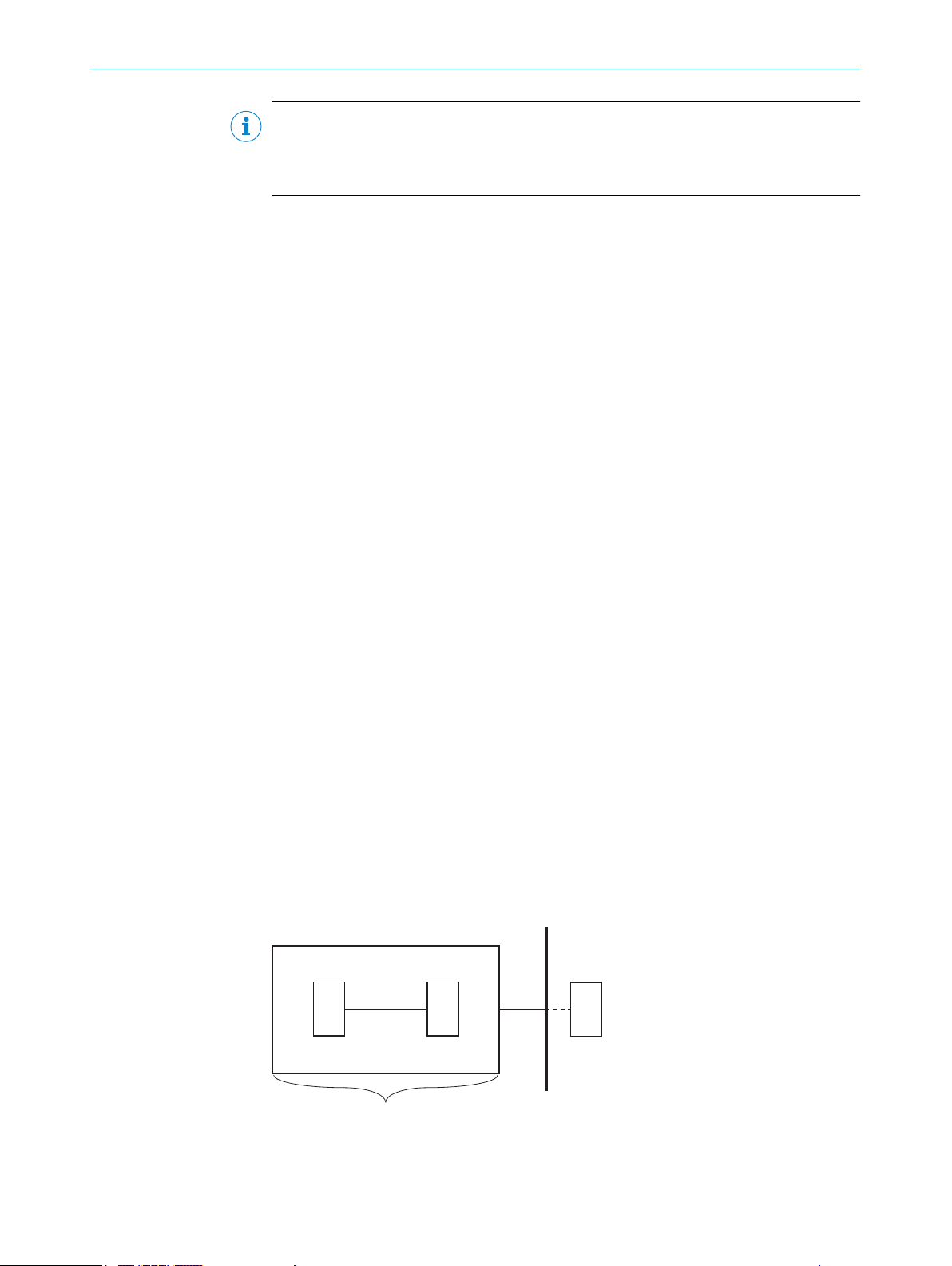
3.6 Limits of the safety system
The safety system ends at all inputs and outputs that are not used to wire the compo‐
nent
s of the safety system.
For detailed information about the interfaces see "Electrical installation", page 23.
The limits of the safety system are presented in abstract and general terms in the figure
below:
14
O PE R AT I NG IN S TR U CT I ON S | Safe Entry Exit 8021675/ZV26/2019-05-13 | SICK
Figure 1: Limits of the safety system
Sensors
1
Subject to change without notice
Page 15

3.7 Functions
PRODUCT DESCRIPTION 3
Logic (safety relay or safety controller)
2
Sub-safety function
3
Wiring between sensors and logic
4
Wiring between safety system components and components outside the safety system
5
Limit of the safety system
6
Components outside the safety system, e.g., actuators, safety capable input devices, or
7
gher-level controller
hi
The Safe Entry Exit safety system offers the following functions:
ing function
Mut
•
The safety controller monitors the signal change from requesting the muting
°
function and from the output signal switching devices of the Type 4 electrosensitive protective device and if necessary, switches to the safe state, see
"Muting function", page 40.
Time Extension Function
•
After a correct initiation sequence of the muting function, the maximum dura‐
°
tion of the muting function can be extended, see "Time Extension Function",
page 41.
Hold to run device
•
When the safety system has switched to the safe state, the hold to run device
°
is used to place the conveyor in motion while the material is blocking the pro‐
tective field of the Type 4 electro-sensitive protective device. see "Hold to run
device", page 42.
1 of n timing sets
•
This function makes it possible to select different transport speeds and mate‐
°
rial lengths, see "1 of n timing sets", page 43.
8021675/ZV26/2019-05-13 | SICK OP E RA T IN G I N ST R UC T IO N S | Safe Entry Exit
Subject to change without notice
15
Page 16
4 P
ROJECT PLANNING
4 Project planning
4.1 Manufacturer of the machine
DANGER
H
azard due to lack of effectiveness of the protective device
In the case of non-compliance, it is possible that the dangerous state of the machine
may not be stopped or not stopped in a timely manner.
Use of the safety system requires a risk assessment. Check whether additional
b
protective measures are required.
Comply with the applicable national regulations derived from the application (e.g.,
b
work safety regulations, safety rules, or other relevant safety guidelines).
The safety system was developed under consideration of typical application cases. A
tial safety function can be implemented with the safety system in these application
par
cases. The manufacturer must check whether the safety system is suitable for its spe‐
cific application case (risk assessment).
If the thorough check shows that the safety system is not suitable for the specific appli‐
cation case, the safety system can be used as a basis for an individualized develop‐
ment suitable for the specific application case. This case will not be considered further
in this document.
In any event, additional work is necessary for the safety system to be used, e.g. subse‐
quent configuration of the safety controller.
The manufacturer has the following duties:
Executing a risk assessment.
b
Verifying and validating the safety functions.
b
Integrating the individual components in accordance with the appropriate stan‐
b
dards.
Please note that C standards have priority compared to statements about this
b
safety system.
4.1.1 Calculation of the performance level
Complete subsystems for SISTEMA available on the internet for this safety system can
be used t
Three subsystems are available:
•
•
•
WARNING
C
ertain indicators for the individual components were used as the basis for calculating
the values for the subsystems. Accordingly, the subsystems are only valid if the selected
components of the safety system meet all requirements, see "Components required",
page 11.
o calculate the achieved performance level.
Safe Entry Exit with a standard control as a higher-level control (requirements see
"Requirements for the higher-level control", page 13)
Safe Entry Exit with a safety controller as a higher-level control (requirements see
"Requirements for the higher-level control", page 13)
A separate subsystem for the hold to run device
16
During the development of the safety system, certain measures against common-cause
aults were implemented or defined. Some of these measures must be taken into
f
account during implementation, see "General requirements", page 23.
O PE R AT I NG IN S TR U CT I ON S | Safe Entry Exit 8021675/ZV26/2019-05-13 | SICK
Subject to change without notice
Page 17

4.2 Operating entity of the machine
DANGER
azard due to lack of effectiveness of the protective device
H
In the case of non-compliance, it is possible that the dangerous state of the machine
may not be stopped or not stopped in a timely manner.
Changes to the electrical integration of the safety system in the machine control
b
and changes to the mechanical mounting of the safety system necessitate a new
risk assessment. The results of this risk assessment may require the entity operat‐
ing the machine to meet the obligations of a manufacturer.
Changes to the safety system’s configuration may impair the protective function.
b
The effectiveness of the safety system must be checked after any change to the
configuration. The person carrying out the change is also responsible for maintain‐
ing the protective function of the safety system.
4.3 Safety Functions
4.3.1 Identifying hazards
This document exclusively considers the monitoring of material transport in or out of
ha
zardous areas and the associated risks.
PROJECT PLANNING 4
Other residual risks, e.g., due to small parts being thrown about, are not considered
and must be considered in detail in the risk analysis, see "Manufacturer of the
machine", page 16.
4.3.2 Enabling material throughput
To move materials into or out of hazardous areas, specific features of the conveyed
ma
terials are used for material detection or to automatically differentiate between
material and people. The protective device is then not actuated during material trans‐
port; however, people are still detected.
4.4 Design
This chapter contains information about implementing the design of the safety system.
An
y design-related contents of the relevant operating instructions also apply.
4.4.1 Type 4 electro-sensitive protective device
P
osition Type 4 electro-sensitive protective device according to EN ISO 13855.
b
If possible, mount the Type 4 electro-sensitive protective device such that the pal‐
b
let for transporting the material on the conveyor does not trigger the Type 4 elec‐
tro-sensitive protective device.
The Type 4 electro-sensitive protective device should only be triggered by the
terial on the pallet. The lowest beam of the Type 4 electro-sensitive protective
ma
device should run just above the surface of the pallet. If this is not practical, the
Type 4 electro-sensitive protective device can also be aligned to the pallet. In this
case, the possibility of persons being situated in an empty pallet must be consid‐
ered in the risk assessment and, if applicable, measures must be taken to prevent
climbing onto an empty pallet. The height of the lowest beam of the Type 4 electrosensitive protective device must be chosen such that it is not possible for persons
to end up in the hazardous area by passing underneath the beam.
Mount t
b
enter the hazardous area by moving past the material.
he Type 4 electro-sensitive protective device such that persons cannot
8021675/ZV26/2019-05-13 | SICK OP E RA T IN G I N ST R UC T IO N S | Safe Entry Exit
Subject to change without notice
17
Page 18

4 P
ROJECT PLANNING
The distance to the opening should be a maximum of 200 mm on each side,
unle
ss otherwise determined in the risk assessment.
If needed the operating entity of the machine must take additional security mea‐
sures, such as mounting electronically monitored swinging flaps.
The type 4 electro-sensitive protective device must only be mounted with the original
accessories of the manufacturer and connected according to the instructions of the
manufacturer. For more notes, see the operating instructions for the Type 4 electro-sen‐
sitive protective device.
4.4.2 Minimum distance between the Type 4 electro-sensitive protective device and the hazardous point
Calculation of minimum distance
T
he minimum distance between the Type 4 electro-sensitive protective device and the
hazardous point is calculated in accordance with EN ISO 13855 as follows:
S = K × T + C + Z
S= K × T + C +700 mm
Formula symbols Description
S Minimum distance
K Approach speed
T Overall system stopping time
C Penetration distance
Z Application-specific supplement
he application-specific supplement is 700 mm. This supplement
T
is made up of 500 mm for differentiating between people and
materials and 200 mm of monitored conveying distance that is
usually the result of the delay time T
tance other than 200 mm is configured, the application-specific
supplement must be adapted accordingly.
. If a conveying dis‐
Clearance
The risk assessment must determine to what degree people can misuse a process sig‐
ended for transport goods in order to activate the muting function themselves (by
nal int
interrupting the Type 4 electro-sensitive protective device). This possibility must be
taken into account in particular with transport goods which can be taken off the con‐
veyor by hand.
A person who activates the muting function will be detected at the latest because the
muting period is too short. However, the person is already in the hazardous area at this
point.
The application-specific supplement Z is not needed if the risk assessment concludes
that it is not possible for people to be on the conveyor or AGV/AGC.
4.4.3 Design of the material opening
The material transportation opening should be designed so as to provide free space of
ma
ximum 200 mm next to the material when the material is passing through. If the risk
assessment concludes that even with a larger free space it is still impossible for per‐
sons to end up in the hazardous area by passing next to the material, the free space
can be adjusted accordingly.
If the free space next to the material is larger than 200 mm, it should be at least
500 mm to prevent the crushing of persons between the material and the Type 4 elec‐
tro-sensitive protective device or other machine parts. In this case, additional protective
measures must be taken, e.g., installation of electrically monitored swing doors.
18
O PE R AT I NG IN S TR U CT I ON S | Safe Entry Exit 8021675/ZV26/2019-05-13 | SICK
Subject to change without notice
Page 19

It must be clarified during the risk assessment whether it is possible for persons to be
1
1
on t
taken, such as preventing the possibility of climbing onto the transported material or
monitoring the maximum transport material height.
1
4.4.4 Conveyor speed
The speed at which the material is transported on the conveyor must be calculated in
t
PROJECT PLANNING 4
op of the material being transported. If this is the case, suitable measures must be
200 mm maximum
he previously determined sequence.
If different conveyor speeds are used, up to four different timing sets can be set in the
safety controller. The currently valid timing set must be selected via signals from the
higher-level control, see "1 of n timing sets", page 43.
The maximum possible speed of the conveyor depends on the drive as well as the mea‐
surement accuracy of the muting function request. The muting function request must
be sent when the material is a maximum of 200 mm from the Type 4 electro-sensitive
protective device. If the risk assessment concludes that persons in front of the material
definitely need more than 200 mm, the distance can be adjusted accordingly.
4.4.5 Calculating response times and stopping times
Response time of the safety system
T
he response time of the safety system when the muting function is deactivated is cal‐
culated as follows:
T
Safety System
T
Safety System
Formula symbols Description
T
afety System
S
T
SPE
E
T
CPU cycle time
= T
= T
+6.5 ms +2 × T
ESPE
+2 × T
ESPE
CPU cycle time
Response time of the safety system
Response time of the Type 4 electro-sensitive protective device
that is in use (see the relevant operating instructions).
Cycle time of the Flexi Soft safety controller
CPU cycle time
+11 ms
+4.5 ms
The additional 11 ms correspond to the response time of the digital inputs and outputs
he Flexi Soft safety controller.
of t
Stopping time of the application
T = T
Safety System
Formula symbols Description
T Stopping time of the application
T
S
8021675/ZV26/2019-05-13 | SICK OP E RA T IN G I N ST R UC T IO N S | Safe Entry Exit
Subject to change without notice
afety System
+ T
deceleration
+ T
others
Response time of the safety system
19
Page 20

ESPE Type 4
Independent Control System
Process
sensor
Control unit
(e. g. PLC)
Signal MR
Muting request
Signal TE
Time extension
OSSD
Safety System
Safety Controller Flexi Soft
Safety Outputs
Inputs
Outputs
CPU
Logic
4 PROJECT PLANNING
Formula symbols Description
T
dece
leration
T
thers
o
4.5 Integrating the equipment into the electrical control
NOTE
veral safety functions are generally necessary in order to ensure a safe design for the
Se
entire application. This requires additional components that are not part of the safety
system, such as switches, fuses, and contactors. The circuit diagrams contain informa‐
tion on wiring the safety system with additional components within an application.
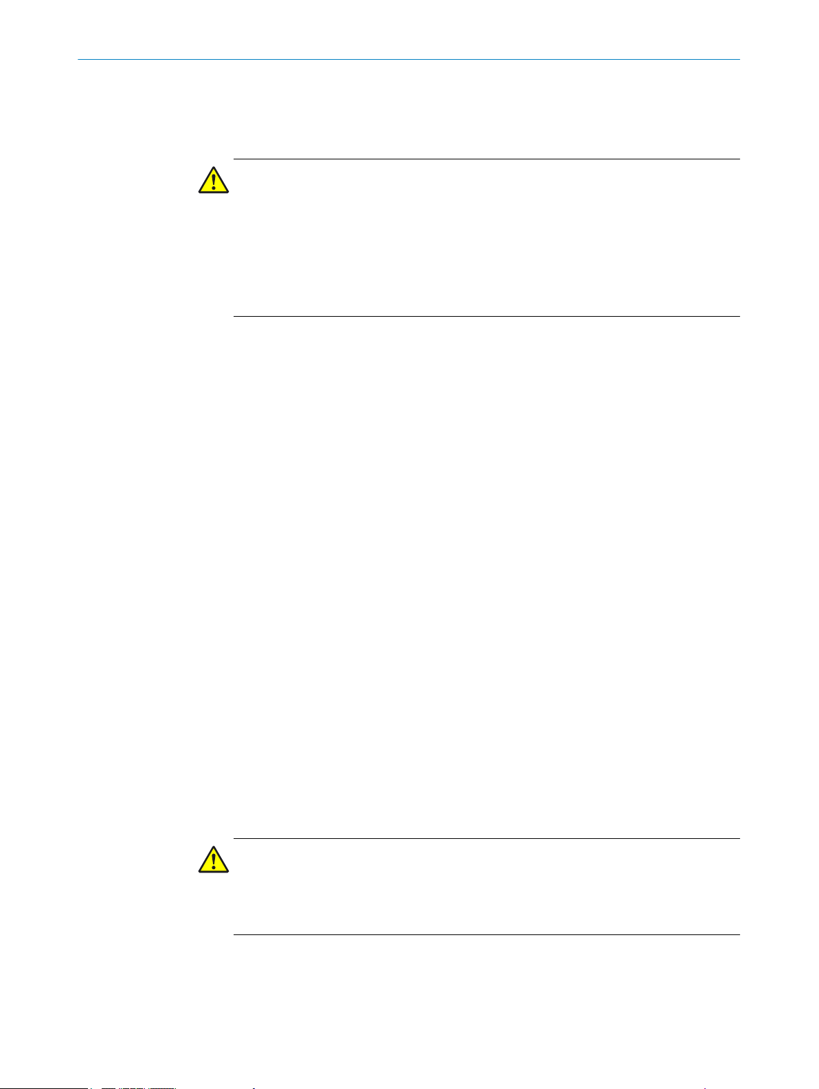
4.5.1 Circuit diagram
A more detailed circuit diagram for Safe Entry Exit is available online:
www
.sick.com/Safe_Entry_Exit
The components of Safe Entry Exit are interconnected per the following diagram:
Machine stopping time
Other application-specific variables, such as the response time of
the contactors
20
Figure 2: Block diagram for Safe Entry Exit
T
able 2: Block diagram terminology
ESPE Type 4 The electro-sensitive protective device must conform to Type 4 and
c
an be a safety light curtain, for example.
Independent Control Sys‐
tem
The signals of the higher-level control are part of the initiation of
the muting function. The combination of process sensor and con‐
trol unit is an example. The higher-level control is not part of the
safety system.
Process Sensor The process sensor forwards information about transported mate‐
rials to the control unit. It must not be easy to manipulate this
information, e.g., by modifying it.
Control unit The control unit is a functional unit of the process that controls the
command pr
ocessing sequence. It can be a standard programma‐
ble logic controller, for example.
OSSD Safety output of the Type 4 electro-sensitive protective device con‐
nected in pairs and subject to dual-channel evaluation.
Signal MR - Muting request This signal requests the muting function.
Signal TE - Time extension This signal is used to request the time extension function.
Safety Controller The safety controller monitors the signal change and switches
cordingly.
O PE R AT I NG IN S TR U CT I ON S | Safe Entry Exit 8021675/ZV26/2019-05-13 | SICK
Inputs Safety controller inputs
ac
Subject to change without notice
Page 21

PROJECT PLANNING 4
CPU Logic The CPU logic is used to set the timing and sequence of the sig‐
nals
.
Outputs Safety controller outputs
4.5.2 Testing plan
For the detailed pin assignment of the safety controller, see "S
afety controller pin
assignment", page 23.
The safety system must be thoroughly checked by appropriately qualified safety person‐
ne
l during commissioning, after changes at regular intervals.
The regular thorough checks serve to assess the effectiveness of the safety system and
to identify defects as a result of changes or other influences (e.g., damage or manipula‐
tion).
The manufacturer and user must define the type and frequency of the thorough checks
on the basis of the application conditions and the risk assessment. Determination of
the thorough checks must be documented in a traceable manner.
A thorough check must be carried out during commissioning and following modifi‐
•
cations.
The regular thorough checks of the safety system must fulfill certain minimum
•
requirements. The minimum requirements for the thorough check of the safety
system comply at least with the sum of the minimum requirements for the thor‐
ough check of the components of the safety system (see operating instructions of
the components).
In many cases, depending on the application conditions, the risk assessment can
•
determine that further thorough checks are required.
Further chapters
T
horough check, see "Commissioning", page 37
•
Checklist for initial commissioning and commissioning, see "Annex", page 48
•
8021675/ZV26/2019-05-13 | SICK OP E RA T IN G I N ST R UC T IO N S | Safe Entry Exit
Subject to change without notice
21
Page 22

5 MOUN
TING
5 Mounting
NOTE
Inf
ormation is included in the operating instructions for the components.
5.1 Mounting conditions for the electro-sensitive protective device
For mounting conditions see "T
ype 4 electro-sensitive protective device", page 17.
22
O PE R AT I NG IN S TR U CT I ON S | Safe Entry Exit 8021675/ZV26/2019-05-13 | SICK
Subject to change without notice
Page 23

6 Electrical installation
NOTE
Inf
ormation is included in the operating instructions for the components.
6.1 General requirements
The following measures to prevent common-cause failures must be considered during
lectrical installation:
e
Separation of the signal pathways for the safety system signals, e.g. by laying sep‐
•
arate cables or shielding the signal paths separately.
Protection against overvoltage, overcurrent, etc. according to the manufacturer’s
•
instructions for the individual components.
Mechanical fastening of the wiring of the pushbutton for the manual muting
•
device, e.g. with cable ties.
Measures for controlling the consequences of voltage failure, voltage fluctuations,
•
overvoltage and undervoltage in the voltage supply of the process controller.
6.2 Safety controller pin assignment
ELECTRICAL INSTALLATION 6
Figure 3: Safety controller setup
8021675/ZV26/2019-05-13 | SICK OP E RA T IN G I N ST R UC T IO N S | Safe Entry Exit
Subject to change without notice
23
Page 24

6 ELE
CTRICAL INSTALLATION
Table 3: Modules of the safety controller
Module 1 Main module FX3-CPUx
Module 2 I/O module FX3-XTIO
Module 3 (optional) I/O module FX3-XTDI
Module 2: Input configuration for FX3-XTIO module
T
able 4: Function of the connections
Connection Function
l1/l2 B100.1 Type 4 electro-sensitive protective device
l3 B100.2 Muting function request
l4 B100.2 Time extension
l5 S300 Pushbutton for the reset function
l6 S200 Hold to run device (connected to test output X2)
Module 2: Output configuration for FX3-XTIO module
T
able 5: Function of the connections
Connection Function
Q1/Q2 Q100 Safety release
Q3 P100 Safe Entry Exit Status
Q4 P101 Hold to run device status
X2 Test output for supply of S200 hold to run device
Module 3: Input configuration for FX3-XTDI module
T
his module is optional and is only required if timings need to be set for different con‐
veyor speeds or different material sizes.
Table 6: Function of the connections
Connection Function
l1 S301.1 Timing 1
l2 S301.2 Timing 2
l3 S301.3 Timing 3
l4 S301.4 Timing 4
6.3 Interfaces and signals
Signals for triggering the muting function
T
his safety system requires two digital 24 V signals from a higher-level control to trigger
the muting function. These signals are part of the initiation sequence for the muting
function.
The first signal for requesting the muting function, MR (Muting Request – in the Flexi
Soft project file also: PLC_Request), detects approaching material with a rising edge
and remains at logical high while an interruption of the Type 4 electro-sensitive protec‐
tive device is expected.
The second signal, TE (Time Extension), changes its status in the opposite direction
from the MR signal.
24
O PE R AT I NG IN S TR U CT I ON S | Safe Entry Exit 8021675/ZV26/2019-05-13 | SICK
Subject to change without notice
Page 25

ELECTRICAL INSTALLATION 6
This opposite behavior is monitored by the safety controller. When the muting function
is ac
tive, the TE signal can be used to extend the maximum duration of the muting func‐
tion, such as if the conveyor has to be stopped while the protective field of the Type 4
electro-sensitive protective device is occupied by material.
The following four signal combinations are possible:
Table 7: Possible signal combinations
MR signal TE signal Meaning
High Low Muting function request
Low High No muting function request
High High Time extension for muting function required
Low Low Error
1)
This signal combination is only valid following successful initiation of the muting function. Otherwise a
fault is output.
Signals for timing set selection
U
p to four optional signals can be used by the higher-level control to select different
timing sets for multiple conveyor speeds or different material sizes. These signals must
be coded as 1 of n.
1)
For more information see "1 of n timing sets", page 43.
Up to four timing sets can be configured and selected accordingly via signals. The fol‐
lowing table describes the signals required to select the sets, depending on the number
of configured timing sets. Configuring only one set is equivalent to deactivating the Tim‐
ing Set selection function.
The value 1 means logical High (24 V signal) and the value 0 means logical Low.
“-” means that this signal is not required.
Table 8: Relationships between configured sets
Number of con‐
figured timing
sets
1 Timing Set configured
Timing Set 1 - - - -
2 Timing Sets configured
Timing Set 1 1 0 - -
Timing Set 2 0 1 - -
3 Timing Sets configured
Timing Set 1 1 0 0 -
Timing Set 2 0 1 0 -
Timing Set 3 0 0 1 -
4 Timing Sets configured
Timing Set 1 1 0 0 0
Timing Set 2 0 1 0 0
Timing Set 3 0 0 1 0
Timing Set 4 0 0 0 1
Signal Timing Set1Signal Timing Set2Signal Timing Set3Signal Timing Set
4
8021675/ZV26/2019-05-13 | SICK OP E RA T IN G I N ST R UC T IO N S | Safe Entry Exit
Subject to change without notice
25
Page 26

7 CONFIGURATION
7 Configuration
7.1 Requirements on software and firmware
Configuration of the safety system requires at least the following versions of the soft‐
are or firmware:
w
Table 9: Minimum versions
Software and firmware Minimum version
Flexi Soft Designer 1.8.0 SP1
Firmware FX3-CPUx 4.0
Firmware FX3-XTIO 3.0
Process software requirements
T
he software source code for the higher-level controller influences the safety applica‐
tion. This relates to the generation and timing of the MR and TE signals for requesting
the muting function. The corresponding section of source code must therefore be vali‐
dated during commissioning.
7.2 Pre-configured project files
Reference source
Pr
e-configured project files for the safety system are available under the following link:
www.sick.com/Safe_Entry_Exit
Export file
In addit
ion to the project files provided, an export file is available on the Internet. This
corresponds to the hardware configuration and logic of the project file with an activated
Timing Set Selection function, but it can be imported into any Flexi Soft CPU module
(firmware version ≥ 4.00).
CPU3 module only:
1. Check CPU cycle times and clock generators.
2. If necessary, adjust the settings to optimize the CPU cycle time.
7.2.1 Checking the checksums of the project files
Approach
1.
Open the required project file in the configuration software or import the required
export file.
2. Click on Hardware configuration.
3. In the Info selection window, click on info.
4. Make sure that the checksum that is displayed corresponds to one of the following
checksums:
Table 10: Checksums
Description Checksum
Project file with activated Timing Set Selection function 0xF3E6EDD7
Project file with deactivated Timing Set Selection function 0xA1EC4147
Checksums of the export file in combination with the relevant Flexi Soft CPU
CPU0 0xF3E6EDD7
CPU1 0x330BBBC5
26
O PE R AT I NG IN S TR U CT I ON S | Safe Entry Exit 8021675/ZV26/2019-05-13 | SICK
Subject to change without notice
Page 27

Description Checksum
CPU2 0x330BBBC5
CPU3 0x54476CD3
Complementary information
ging the configuration logic or the hardware configuration changes the checksum.
Chan
7.2.2 Standard values for timing sets
Important information
WARNING
he indicated application values do not correspond with the values of the target appli‐
If t
cation, the standard values for the timing sets must be adjusted accordingly.
Standard values for timing sets
T
able 11: Standard values for timing sets
T
Init
iation
T
arance
Cle
T
ermination
T
T
Min
T
x
Ma
CONFIGURATION 7
Timing Set 1 Timing Set 2 Timing Set 3 Timing Set 3
2,000 ms 660 ms 400 ms 280 ms
2,000 ms 660 ms 400 ms 280 ms
2,000 ms 660 ms 400 ms 280 ms
131 (=13 s) 45 (=4.4 s) 27 (=2.6 s) 20 (=1.9 s)
141 (=14 s) 47 (=4.6 s) 29 (=2.8 s) 21 (=2 s)
The four different timing sets can be selected sequentially using the Timing Set Selec‐
ion function. In the project file with a deactivated Timing Set Selection function, Timing
t
Set 1 is selected as standard.
Assumed application values
The standard values of the timing sets were calculated using the following application
values:
Material length: 1,200 mm
•
Conveyor speeds:
•
Timing Set 1: 0.1 m/s
°
Timing Set 2: 0.3 m/s
°
Timing Set 3: 0.5 m/s
°
Timing Set 4: 0.7 m/s
°
Clock generator 0:
•
Clock period: 25 (= 100 ms)
°
Pulse time: 5 (= 20 ms)
°
Clock generator 2:
•
Clock period: 1,500 (= 6 s)
°
Pulse time: 25 (= 100 ms)
°
All the data relate to a CPU cycle time of 4 ms. If the CPU cycle time is longer, the set‐
tings of the clock generators must be adjusted accordingly.
Complementary information
ging the standard values of the timing sets changes the checksum.
Chan
8021675/ZV26/2019-05-13 | SICK OP E RA T IN G I N ST R UC T IO N S | Safe Entry Exit
Subject to change without notice
27
Page 28

ONFIGURATION
7 C
Further topics
"C
onfiguration of PLC monitoring & override", page 35
•
7.3 Opening project file
1. Start Flexi Soft Designer.
2.
Click on Project.
3. Click on Open.
4. Select the project file.
5. Click on Open.
✓
The project file opens. The Hardware configuration view appears.
In the Configuration area, the entire hardware configuration of the Flexi Soft safety con‐
troller and the connected devices is displayed graphically.
7.4 Configuring logics for Flexi Soft CPU
1. Move the mouse cursor to the L
2. Click on Logic editor.
✓
The Logic editor view opens. The Sequence monitoring page appears.
7.4.1 Creating or deleting links
The logics in the Flexi Soft Designer mainly consist of the following elements:
afety controller inputs
S
•
Safety controller outputs
•
Function blocks with inputs and outputs
•
Links connect these elements. Links are represented as lines. Every element contains
blue anchor points which represent the inputs and outputs of the elements. A link can
only be created between the anchor point on the right side of an element and the
anchor point on the left side of another element.
Creating link
1.
Click and hold the blue anchor point on the right side of an element.
2. Move and release the mouse cursor on the blue anchor point on the left side of an
element.
✓
A link is created between 2 elements.
Deleting link
1. Click on the link between 2 elements.
2. Press the Del pushbutton.
3. In the Delete page dialog box, click on the Yes button.
✓
The link is deleted.
ogic editor button.
7.5 Transfer configuration
T
ransmit configuration to the Flexi Soft main module (see operating instructions
b
8012998).
28
O PE R AT I NG IN S TR U CT I ON S | Safe Entry Exit 8021675/ZV26/2019-05-13 | SICK
Subject to change without notice
Page 29

7.6 Adjust configuration
Important information
WARNING
he safety-related application software is expanded and used for other safety func‐
If t
tions, the additional function blocks must be strictly separated, on separate logic
pages, from the Safe Entry Exit function blocks.
The logic pages for Safe Entry Exit may only be changed as described in this document.
Any other changes can impair the safety of the system.
NOTE
C
onfigured time values are subject to a tolerance during evaluation. This depends on
the function blocks used and CPU cycle time, among other things.
For detailed information on the time evaluation in Flexi Soft logic, see the Flexi Soft
operating instructions in the Flexi Soft Designer software (part number 8012998).
Adjust configuration
T
he configuration must be adjusted on the following logic pages:
CONFIGURATION 7
•
•
•
All user-defined function blocks in the safety-related application software are locked
and do not have to be configured.
Data relating to the speed of the conveyor and the size of the material being trans‐
ported are needed for the settings of the Timer and Event counter function blocks.
Complementary information
An Ex
Excel tool can help with calculating the settings for the function blocks.
7.6.1 Configuration of S
“Initiation” network
Sequence monitoring
Time monitoring
PLC monitoring & override
cel tool is included in the download archive, together with the project file. This
equence monitoring
Figure 4: “Initiation” network
his network contains an Adjustable off-delay timer function block. Up to four different
T
times can be configured for different conveyor speeds, depending on the application.
These times can be selected using the optional Timing Set Selection, see "Interfaces
and signals", page 24. If this function is not used, only the Off delay time 1 parameter
needs to be configured.
8021675/ZV26/2019-05-13 | SICK OP E RA T IN G I N ST R UC T IO N S | Safe Entry Exit
Subject to change without notice
29
Page 30

7 C
ONFIGURATION
The time set here is the initialization time window between the request from the higherle
vel controller and the interruption of the Type 4 electro-sensitive protective device. By
configuring a suitable initialization time window, it is possible to ensure that people in
front of the material being transported are detected.
Configuration instructions:
The delay times to be configured correspond to the time required for a 200 mm convey‐
ing line at the respective conveyor speed. It is forbidden to set this value above 4 s.
T
initiation
=
0.2m
V
conveyor
A shorter delay time can be set if the accuracy of the signals from the higher-level con‐
rol is precise enough to ensure the availability of the system.
t
WARNING
ious injury may occur due to unreliable presence detection.
Ser
Monitoring the 200 mm conveying distance between requesting the Safe Entry Exit
function and the time at which the protective field of the Type 4 electro-sensitive protec‐
tive device is interrupted ensures that people in front of the material being transported
will be detected.
The calculation of T
is safety-related.
initiation
If the risk assessment concludes that people in front of the material definitely need
more than 200 mm of space, the distance can be adjusted accordingly.
“Termination” network
Figure 5: “Termination” network
T
his network includes the two Adjustable on-delay timer function blocks. Up to four differ‐
ent times can be configured for different conveyor speeds, depending on the applica‐
tion. These times can be selected using the optional Timing Set Selection, see "Inter‐
faces and signals", page 24. If this function is not used, only the On delay time 1 parame‐
ter needs to be configured.
The switch-on delay time set in the upper function block is the time needed for the pro‐
tective field of the Type 4 electro-sensitive protective device to be released again after
the muting function has ended.
30
The switch-on delay time configured in the above function block also correlates to the
size tolerance for gaps between the conveyed materials.
The switch-on delay time configured in the lower function block refers to the time after
which the muting function is ended, following the end of the request from the higherlevel control.
O PE R AT I NG IN S TR U CT I ON S | Safe Entry Exit 8021675/ZV26/2019-05-13 | SICK
Subject to change without notice
Page 31

CONFIGURATION 7
Configuration instructions:
T
he delay times to be configured correspond to the time required for a 200 mm convey‐
ing line at the respective conveyor speed. It is forbidden to set this value above 4 s.
T
clearance
T
=
termination
Tclearance corresponds to the specified delay time after the protective device has been
released and until the muting function is ended.
The delay time for the lower function block can be reduced or even deactivated (config‐
ured time = 0) if a quicker response is required to the end of the request from the
higher-level control system.
WARNING
ious injury may occur due to unreliable presence detection.
Ser
Monitoring the 200 mm conveying distance after unlocking the protective field of the
Type 4 electro-sensitive protective device ensures that a gap larger than 200 mm
between the conveyed material will not be tolerated. Monitoring a 200 mm line after
the end of the request for the muting function ensures that people located between or
behind the material being transported will be detected.
The calculation of T
clearance
=
0.2m
V
conveyor
and T
termination
is safety-related.
7.6.2 Configuration of T
“Time monitoring general” network
Figure 6: “Time monitoring general” network
T
his network includes two Clock generator function blocks, which must be configured.
The configuration of both clock generator function blocks depends on the CPU cycle
time of the respective project. The basic CPU cycle time of a project with an FX3-CPU0
module is 4 ms, but this can rise if additional function blocks or other FX3-CPUx mod‐
ules are used.
ime monitoring
Configuration instructions:
T
he settings for the upper Clock generator function block only have to be configured if the
CPU cycle time of the finished project file does not equal 4 ms. If the cycle time is not
4 ms, the value of the clock period must be changed so that the resulting clock period
equals 6 s. The values for the most common cycle times are set out in the table below:
8021675/ZV26/2019-05-13 | SICK OP E RA T IN G I N ST R UC T IO N S | Safe Entry Exit
Subject to change without notice
31
Page 32

7 C
ONFIGURATION
Table 12: Values for common cycle times
CPU cycle time Value for the clock period setting
4 ms 1,500
8 ms 750
12 ms 500
When configuring the lower c
lock generator function block, it is only necessary to set the
clock period. The resulting clock period depends on the CPU cycle time. If changes in
the safety-related application software affect the CPU cycle time, the settings for this
function block must be adjusted accordingly.
The resulting clock period defines the increments at which the minimum and maximum
duration of the muting function can be set and is therefore important for calculating
and configuring these times.
In the calculation formulas for the following two networks, the cycle time of this Clock
generator function block is referred to as T
clock period
. We recommend setting the cycle
time to around 100 ms.
“Min time monitoring” network
32
Figure 7: “Min time monitoring” network
his network includes four Event Counter (up) function blocks that must be configured. Up
T
to four different timings for the different conveyor speeds or different material sizes can
be configured.
Each of the four Event Counter (up) function blocks corresponds to one of the timings that
can be selected using the Timing Set Selection function. The uppermost Event Counter
(up) function block defines Timing 1, while the lowest, in accordance with the ascending
order, defines Timing 4.
O PE R AT I NG IN S TR U CT I ON S | Safe Entry Exit 8021675/ZV26/2019-05-13 | SICK
Subject to change without notice
Page 33

CONFIGURATION 7
The value set in this function block determines the minimum duration of the muting
f
unction. If the muting function ends before this time has elapsed, an error is output.
Configuration instructions:
The configuration of the minimum time in this network is based on the counting of peri‐
ods at a defined clock with a defined overflow value.
The defined clock periods are set in the Time monitoring general network, see "Configura‐
tion of Time monitoring", page 31.
The overflow values for the various timings must be set in the Event Counter (up) function
blocks in this network. If the Timing Set Selection function is not used, only the upper‐
most Event Counter (up) function block has to be configured. The time required until the
overflow value for the respective Event Counter (up) function block is reached with the pre‐
set clock determines the minimum duration of the muting function.
The minimum duration of the muting function is calculated using the following formula.
The material length l
To calculate the minimum duration of the muting function, a material length l
less than 500 mm is not permitted.
T
Min
= (l
– tolerance) / V
goods
Recommended value for tolerance: 0.1 m
and conveyor speed V
goods
+ T
Conveyor
Clearance
conveyor
= T
are needed for this.
clock period
× ( a
overflow
–1)
goods
of
If l
- tolerance is less than 0.5 m, the value must be rounded up to 0.5 m.
goods
We recommend that you define the clock period Tclock period first. The overflow value
to be set for the respective function block can then be calculated using the following
formula.
a
overflow
= (l
goods
– t
olerance
) / (V
Conveyor
× T
clock period
) + (T
Clearance
/ T
clock period
) +1
8021675/ZV26/2019-05-13 | SICK OP E RA T IN G I N ST R UC T IO N S | Safe Entry Exit
Subject to change without notice
33
Page 34

7 C
ONFIGURATION
“Max time monitoring” network
Figure 8: “Max time monitoring” network
T
his network includes four Event Counter (up) function blocks that must be configured. Up
to four different timings for the different conveyor speeds or different material lengths
can be configured.
Each of the four Event Counter (up) function blocks corresponds to one of the timings that
can be selected using the Timing Set function. The uppermost Event Counter (up) function
block defines the timing with the index 1, while the lowest, in accordance with the
ascending order, defines Timing 4.
The value set in this function block determines the maximum duration of the muting
function. If the Type 4 electro-sensitive protective device is still interrupted after this
period has elapsed, an error is output.
Configuration instructions:
T
he configuration of the maximum time in this network is based on the counting of peri‐
ods in a defined clock with a defined overflow value.
The defined clock periods are set in the Time monitoring general network, see "Configura‐
tion of Time monitoring", page 31.
The overflow values for the various timings must be set in the Event Counter (up) function
blocks in this network. If the Timing Set Selection function is not used, only the upper‐
most Event Counter (up) function block has to be configured. The time required until the
overflow value for the respective Event Counter (up) function block is reached with the pre‐
set clock determines the maximum duration of the muting function.
34
The maximum duration of the muting function is calculated using the following formula.
The material length l
and conveyor speed V
goods
are needed for this. T
conveyor
Interruption ESPE
corresponds to the expected muting period of the protective device. It is forbidden to
set this value above 10 min.
O PE R AT I NG IN S TR U CT I ON S | Safe Entry Exit 8021675/ZV26/2019-05-13 | SICK
Subject to change without notice
Page 35

CONFIGURATION 7
T
= T
Ma
x
Interruption ESPE
T
Max
= (l
goods
/ V
It is recommended to first define the clock period T
set for the respective function block can then be calculated using the following formula.
a
= l
overflow
goods
Complementary information
T
able 13: Timing errors
Timing errors Description
End of the maximum duration
he muting function
of t
End of the minimum duration
of the muting function
Conveyor)
/ (V
+ T
+ T
Conveyor
Clearance
Clearance
× T
clock period
= T
clock period
) + (T
× ( a
Clearance
overflow
clock period
/ T
clock period
–1)
. The overflow value to be
) +1
If the Type 4 electro-sensitive protective device is still inter‐
rupted after the maximum duration of the muting function has
elapsed, the safety system goes into error mode.
If the duration of the muting function (muting active time) is
shorter than the calculated minimum duration, the safety sys‐
tem goes into the error state.
7.6.3 Configuration of PL
“Timing Set Selection Monitoring” network
Figure 9: “Timing Set Selection Monitoring” network
T
his is the network where the Timing Set Selection function is configured. In this regard,
it can be decided to activate or deactivate this function.
If the function is deactivated, one timing set is continuously selected and it is not possi‐
ble to switch it.
If this function is activated, it must be determined whether 2, 3 or 4 timing sets are
needed. This determination affects the required signals and accordingly, also the wiring
of these signals see "Interfaces and signals", page 24.
C monitoring & override
Configuration instructions
If the Timing Selection function is not used, all S301.x signals must be separated from
the User mode switch function block.
8021675/ZV26/2019-05-13 | SICK OP E RA T IN G I N ST R UC T IO N S | Safe Entry Exit
Subject to change without notice
35
Page 36

7 CONFIGURATION
Figure 10: Signal pathways when the function is not used
Ins
tead, the signal Static 1 must be connected to Input 1 and signal Static 0 connected
to the remaining inputs. In this configuration, Timing Set 1 is permanently selected. The
Timing Set must be configured as described in "Configuration of Sequence monitoring",
page 29 and "Configuration of Time monitoring", page 31.
When the Timing Set Selection function is used, the number of timing sets must be
specified. The same number of S301.x signals must be connected to the User mode
switch function block. Two timing sets are configured in the following example (n=2).
Figure 11: Signal pathways when the function is used with 2 timing sets
In t
his case the signals must be connected to the input with the same numbering, pro‐
ceeding in sequence. All remaining inputs of the operating mode selector switch func‐
tion block must be connected to the signal Static 0.
All selected timing sets must be configured as described in "Configuration of Sequence
monitoring", page 29 and "Configuration of Time monitoring", page 31.
WARNING
ging the connections of the signals for the Timing Set Selection function is an
Chan
exception during configuration. It is not permitted to change any other connections in
the logic for this safety system since this could impair safety and functioning.
36
O PE R AT I NG IN S TR U CT I ON S | Safe Entry Exit 8021675/ZV26/2019-05-13 | SICK
Subject to change without notice
Page 37

8 Commissioning
8.1 Safety
WARNING
H
azard due to lack of effectiveness of the protective device
Before commissioning the machine, make sure that the machine is first checked
b
and released by qualified safety personnel.
Only operate the machine with a perfectly functioning protective device.
b
DANGER
angerous state of the machine
D
During commissioning, the machine or the protective device may not yet behave as you
have planned.
Make sure that there is no-one in the hazardous area during commissioning.
b
Before commissioning can be performed, project planning, mounting, electrical installa‐
t
ion and configuration must be completed in accordance with this document.
COMMISSIONING 8
8.2 Thorough check
Requirements for the thorough check during commissioning and in certain situations
T
he safety system and its application must be thoroughly checked in the following situa‐
tions:
•
•
•
•
The thorough check ensures the following:
•
•
The thorough checks must be carried out by qualified safety personnel or specially qual‐
ified and authorized personnel and must be documented in a traceable manner.
1. Effectiveness of the protective device for all operating modes selectable on the
2. Make sure that the operating personnel has been instructed in the function of the
Before commissioning
After changes to the configuration or the safety function
After changes to the mounting or the electrical connection
After exceptional events, such as after a manipulation has been detected, after
modification of the machine, or after replacing components
All relevant regulations are complied with and the safety system is effective in all
of the machine’s operating modes
The documentation corresponds to the state of the machine, including the protec‐
tive device
hine in accordance with the checklist for initial commissioning and commis‐
mac
sioning (see "Annex", page 48).
protective device before starting work on the machine. The instruction is the
responsibility of the machine operator and must be carried out by qualified per‐
sonnel.
8021675/ZV26/2019-05-13 | SICK OP E RA T IN G I N ST R UC T IO N S | Safe Entry Exit
Subject to change without notice
37
Page 38

9 MAINTENANCE
9 Maintenance
NOTE
Inf
ormation is included in the operating instructions for the components.
38
O PE R AT I NG IN S TR U CT I ON S | Safe Entry Exit 8021675/ZV26/2019-05-13 | SICK
Subject to change without notice
Page 39

10 Troubleshooting
NOTE
Inf
ormation is included in the operating instructions for the components.
Table 14: Troubleshooting
Error message Possible cause Troubleshooting
Configuration is
valid:
in
PLC signal monitoring
No 16 on-delay timer
Logic execution time
> 20 ms
TROUBLESHOOTING 10
ctivate the Logic execution time optimization
A
•
option in Flexi Soft Designer.
Deactivate unnecessary functions (e.g.
•
Flexi Loop).
For more information, see chapter “Optimiza‐
tion of the logic execution time” in operating
instructions 8012998.
8021675/ZV26/2019-05-13 | SICK OP E RA T IN G I N ST R UC T IO N S | Safe Entry Exit
Subject to change without notice
39
Page 40

1 1
2
4
3
5
MR
TE
ESPE
OSSDs
Muting
active
t
11 O
PERATION
11 Operation
Operation is dependent on integration of the safety system into the application.
11.1 Description of signals
The following abbreviations are used for the individual functions in the following fig‐
ur
es:
Abbreviation Description
MR Muting Request (part of the complementary signal for activating
TE Time Extension (part of the complementary signal for activating
ESPE OSSDs The OSSD signals of the electro-sensitive protective device
Muting active Muting function active
Hold-to-run device Command device with self-actuating reset
Override active Manual muting active
Safe outputs Safe outputs
t
he muting function)
the muting function, in addition to the extension of the muting
function)
11.2 Muting function
The safety controller monitors the signal change of the commands for the muting func‐
ion and the output signal switching devices of the Type 4 electro-sensitive protective
t
device. These signals must follow a defined sequence and a defined timing to activate
and deactivate the muting function. If the safety controller detects a deviation in
sequence or timing, the safe state is activated.
The only exception is if the protective field of the Type 4 electro-sensitive protective
device is not interrupted even though the sequence provides for an interruption. The
error in the sequence is then saved, which means that the safe state is only initiated
once the protective field is interrupted.
Figure 12: Correct sequence for muting function with ending by safety device
40
O PE R AT I NG IN S TR U CT I ON S | Safe Entry Exit 8021675/ZV26/2019-05-13 | SICK
Monitoring of the complementary circuit
1
Interruption of the protective device is expected after a defined time (max. 4 s, depending
2
on t
he speed of the conveyor). The muting function starts when the protective device is
interrupted.
Maximum duration of muting is defined (depending on the length of the material and the
3
speed of the conveyor).
Ending of the muting function after the protective device has been released and a defined
4
delay time has gone by (max. 4 s, depending on the speed of the conveyor).
Subject to change without notice
Page 41

1 1
2
4
3
MR
TE
ESPE
OSSDs
Muting
active
t
OPERATION 11
After the protective device is released and the muting function ends, the request of the
5
ing function must end after a defined time (max. 10 s, fixed value).
mut
Figure 13: Correct sequence for muting function with ending by higher-level control
Monitoring of the complementary circuit
1
Interruption of the protective device is expected after a defined time (max. 4 s, depending
2
on t
he speed of the conveyor). The muting function starts when the protective device is
interrupted.
Maximum duration of muting function is defined (depending on the length of the material
3
and the speed of the conveyor).
Ending of the muting function after the protective device is released and a defined delay
4
time has gone by (max. 4 s, depending on the speed of the conveyor).
After the higher-level control has requested ending the muting function, the protective
device must be released within a defined delay time (max. 4 s, depending on the speed of
the conveyor). Once this delay time has elapsed, the muting function is ended.
11.3 Time Extension Function
Once the muting function is active after a correct initiation sequence, the Time Exten‐
sion (
TE) signal can be used to extend the maximum duration of the muting function.
This function can be necessary in the following situations:
The conveyor must stop while the muting function is active.
•
The materials being transported on the conveyor are placed directly one behind
•
the other at a distance of less than 200 mm or at the distances specified in the
risk assessment.
To activate this function, the Time Extension (TE) signal must be set to HIGH during a
correctly initiated muting function. The signal must remain on HIGH while the protective
field of the Type 4 electro-sensitive protective device is interrupted. Changing to LOW for
a period longer than T
To prevent a sequencing error, the Time Extension (TE) must end before the muting
function request ends or before the muting function is ended due to the release of the
electro-sensitive protective function.
The Time Extension function is limited to a maximum duration of 100 h pro muting
process.
ends the time extension.
Clearance
8021675/ZV26/2019-05-13 | SICK OP E RA T IN G I N ST R UC T IO N S | Safe Entry Exit
Subject to change without notice
41
Page 42

1 1
2
4
3
5
MR
TE
ESPE
OSSDs
Muting
active
t
11 O
PERATION
Figure 14: Correct sequence for Time Extension function
Monitoring of the complementary circuit
1
Interruption of the protective device is expected after a defined time (max. 4 s, depending
2
on t
he speed of the conveyor). The muting function starts when the protective device is
interrupted.
Time Extension function with max. 100 h duration (only allowed if muting function is acti‐
3
vated).
Ending of the muting function after the protective device has been released and a defined
4
delay time (clearance time) has elapsed (max. 4 s, depending on the speed of the con‐
veyor).
After the protective device is released and the muting function ends, the request for the
5
muting function must end after a defined time (max. 10 s, fixed value).
NOTE
W
hile the Time Extension is activated, monitoring of the minimum and maximum mut‐
ing function duration is paused, then continued once the Time Extension ends.
11.4 Hold to run device
When the safety system has switched to the safe state, the hold to run device is used to
place t
he conveyor in motion while the material is interrupting the protective field of the
Type 4 electro-sensitive protective device.
This function can be activated exclusively by activating a spring-back pushbutton.
Requirements for the pushbutton, see "Requirements for hold to run device", page 12.
The hold to run can only be activated if a sequencing error is present and the output
signal switching devices of the Type 4 electro-sensitive protective device are deacti‐
vated. The hold to run ends after the protective field of the Type 4 electro-sensitive pro‐
tective device has become free again, or after 150 s.
The hold to run requires two steps to prevent unintentional activation.
1. When the output signal switching devices of the Type 4 electro-sensitive protective
device are deactivated and the hold to run function is not activated, the springback pushbutton must be pressed for at least 350 ms, up to a maximum of 30 s,
to initiate the hold to run.
2. Once the hold to run is initiated, the two safety outputs of the safety controller are
activated for as long as the spring-back pushbutton is pressed. Once the pushbut‐
ton is released, the safety outputs are deactivated again.
42
O PE R AT I NG IN S TR U CT I ON S | Safe Entry Exit 8021675/ZV26/2019-05-13 | SICK
Subject to change without notice
Page 43

OPERATION 11
Figure 15: Correct sequence for manual muting
The TE signal is not displayed, but must continue to act complementary to the MR signal.
1
Interruption of the protective device is expected after a defined time (max. 4 s, depending
2
he speed of the conveyor).
on t
Ending of the muting function after the muting function request ends and a defined delay
3
time has elapsed (max. 4 s, depending on the speed of the conveyor).
If the muting function ends and the protective device is not released, a safety stop is trig‐
4
gered.
Triggering of manual muting: A pushbutton must be held for at least 350 ms for manual
5
muting (max. 30 s).
The maximum duration of manual muting is 150 s. After this time, manual muting is auto‐
6
matically ended if it is still active.
Manual muting is ended as soon as the protective device is released.
7
When manual muting is active, the pushbutton for manual muting controls safe outputs.
8
11.5 1 of n timing sets
This optional function enables configuration of multiple values for time monitoring of
t
he muting function. It allows the muting function to be set for different conveyor
speeds and different material lengths. This function is configured via timing sets that
contain a value for every configured time see "Adjust configuration", page 29. The cur‐
rently valid timing set must be selected via signals from the higher-level control, see
"Interfaces and signals", page 24.
Up to four of these timing sets can be set up. They must contain the following details:
Maximum time between muting function request and interruption of the Type 4
•
electro-sensitive protective device
Maximum duration of muting function
•
Minimum duration of muting function
•
Length of the delay before the muting function is deactivated after interruption of
•
the protective field of the Type 4 electro-sensitive protective device
Length of the delay before the muting function is deactivated after the muting
•
function request is ended by the higher-level control
NOTE
It is onl
cannot be switched while the muting function is active.
y possible to select the current timing set if the muting function is not active; it
8021675/ZV26/2019-05-13 | SICK OP E RA T IN G I N ST R UC T IO N S | Safe Entry Exit
Subject to change without notice
43
Page 44

12 TECHNICAL DATA
12 Technical data
12.1 Data sheet
Table 15: Safe Entry Exit data sheet
For higher-level control with MTTFd value of at least 10 a
Performance level PL d (ISO 13849-1)
Category Category 3 (ISO 13849-1)
SIL claim limit SILCL2 (EN 62061)
PFHd (mean probability of one dan‐
erous failure per hour)
g
For higher-level control with performance level PL e
Performance level PL e (ISO 13849-1)
Category Category 3 (ISO 13849-1)
SIL claim limit SILCL3 (EN 62061)
PFHd (mean probability of one dan‐
erous failure per hour)
g
Safe Entry Exit manual muting function
Performance level PL d (ISO 13849-1)
Category Category 2 (ISO 13849-1)
PFHd (mean probability of one dan‐
erous failure per hour)
g
Supply voltage U
Ambient operating temperature See operating instructions for the individual components
Storage temperature See operating instructions for the individual components
Air humidity See operating instructions for the individual components
Permissible operating height See operating instructions for the individual components
Safe state The safety-related semiconductor outputs are in the OFF
1)
The external supply voltage must jumper a brief power failure of 20 ms as specified in IEC 60204-1. Suit‐
able power supply units are available as accessories from SICK.
Safe Entry Exit
2.15 × 10
4.53 × 10
5.34 × 10
V
24 V DC (16.8 V DC ... 28.8 V DC) (SELV)
tate.
s
–7
–8
–7
1)
44
O PE R AT I NG IN S TR U CT I ON S | Safe Entry Exit 8021675/ZV26/2019-05-13 | SICK
Subject to change without notice
Page 45

13 Ordering information
13.1 Scope of delivery
Ordering information for the basic package
oduct: Safe Entry Exit basic package
Pr
Type code: SAPPD3E-05X0032
Part number: 1090293
Safe Entry Exit scope of delivery
F
lexi Soft safety controller main module (part number 1043783)
•
Flexi Soft safety controller expansion module - I/O module (8 inputs, 4 outputs)
•
(part number 1044125)
Flexi Soft safety controller system plug (part number 1043700)
•
13.2 Safe Entry Exit ordering data
Table 16: Safe Entry Exit ordering data
Description Type code Part number
Flexi Soft CPU0 FX3-CPU000000 1043783
System plug for FX3-CPU0 FX3-MPL000001 1043700
I/O module, 8 safe inputs, 4 safe outputs,
g-in dual level spring terminals
plu
Connection cables for the sender and receiver
to the Type 4 electro-sensitive protective
device (type and connection type depend on
the Type 4 electro-sensitive protective device
used)
ORDERING INFORMATION 13
FX3-XTIO84002 1044125
Table 17: Safe Entry Exit ordering data
Type 4 electro-sensitive protective device from
SIC
K
deTec4 Prime www.sick.com/deTec4_Prime
deTec4 Core www.sick.com/deTec4_Core
miniTwin4 www.sick.com/miniTwin4
C4000 Standard www.sick.com/C4000_Standard
C4000 Standard ATEX II 3G/3D www.sick.com/c4000_stan‐
C4000 Advanced www.sick.com/C4000_Advanced
C4000 Advanced Ex www.sick.com/C4000_Advanced_Ex
C4000 Advanced ATEX II 3G/3D www.sick.com/
C4000 Select www.sick.com/C4000_Select
C4000 Select Ex www.sick.com/C4000_Select_Ex
M4000 Advanced Curtain www.sick.com/M4000_Advanced_Curtain
deTec4 Core IP69K www.sick.com/deTec4_Core_IP69K
deTec4 Core Ex www.sick.com/deTec4_Core_Ex
deTem4 Core www.sick.com/deTem4_Core
deTem4 Core IP69K www.sick.com/deTem4_Core_IP69K
M4000 Standard www.sick.com/M4000_Standard
Product page
ard_atex_II_3G_3D
d
c4000_ad
vanced_atex_II_3G_3D
8021675/ZV26/2019-05-13 | SICK OP E RA T IN G I N ST R UC T IO N S | Safe Entry Exit
Subject to change without notice
45
Page 46

13 ORDERING INFORMATION
Type 4 electro-sensitive protective device from
SIC
K
M4000 Standard A/P www.sick.com/m4000_Standard_A_P
M4000 Standard A/P in IP69K Housing www.sick.com/M4000_Stan‐
M4000 Advanced www.sick.com/M4000_Advanced
M4000 Advanced A/P www.sick.com/M4000_Advanced_A_P
M4000 area www.sick.com/M4000_Area
13.3 Ordering data for Safe Entry Exit components
The following components are not included in the scope of delivery. They must be
lected as appropriate for the application and ordered separately:
se
Table 18: Safe Entry Exit ordering data
Description Type code Part number
Hold to run pushbutton Depending on manufac‐
Reset function pushbutton Depending on manufac‐
Higher-level control Depending on manufac‐
Product page
ard_A_P_in_IP69K_Housing
d
urer
t
urer
t
turer
Depending on
manufacturer
Depending on
manufacturer
Depending on
manufacturer
46
O PE R AT I NG IN S TR U CT I ON S | Safe Entry Exit 8021675/ZV26/2019-05-13 | SICK
Subject to change without notice
Page 47

14 Spare parts
14.1 Safe Entry Exit spare parts
Table 19: Ordering data for Safe Entry Exit spare parts
Product Type code Part number
Flexi Soft safety controller main module FX3-CPU000000 1043783
Flexi Soft safety controller expansion module -
I/O module (8 in
Flexi Soft safety controller system plug FX3-MPL000001 1043700
puts, 4 outputs)
SPARE PARTS 14
FX3-XTIO84002 1044125
8021675/ZV26/2019-05-13 | SICK OP E RA T IN G I N ST R UC T IO N S | Safe Entry Exit
Subject to change without notice
47
Page 48

15 ANNEX
15 Annex
15.1 Checklist for initial commissioning and commissioning
This checklist should be retained and kept with the machine documentation to serve as
eference during recurring thorough checks.
r
This checklist is not a substitute for initial commissioning or periodic thorough checks
by qualified safety personnel.
Checklist for validation of hardware implementation
T
able 20: Hardware implementation checklist
No. Requirement Comment Result OK?
1.1 Is the Type 4 electro-sensitive pro‐
t
ective device according to
EN 61496-1 and was it installed
per manufacturer instructions?
1.2 Was EN ISO 13855considered
when positioning the Type 4 elec‐
tro-sensitive protective device?
1.3 Is it necessary for the lowest
beam of the Type 4 electro-sensi‐
tive protective device to only
detect material (e.g. no empty pal‐
lets), and if yes, is this the case?
(Consider risk assessment)
1.4 Are functions of the Type 4 elec‐
ro-sensitive protective device that
t
affect the direct correlation
between the status of the protec‐
tive field, and the status of the
output signal switching device,
deactivated?
2 Is the access to the hazardous
area blocked by material (remain‐
ing gaps smaller than 200 mm) or
have other measures been taken
to prevent access while material is
passing through the protective
field of the electro-sensitive pro‐
tective device?
3 Are the hold to run device and the
reset function pushbutton posi‐
tioned such that when they are
being operated, the person oper‐
ating them has a complete view of
the hazardous area, however can‐
not enter it?
4 Is the Flexi Soft system installed
per manuf
5 Were measures taken for control‐
ling the effects of voltage failure,
voltage fluctuations, overcurrent
or undercurrent in the voltage
supply of the independent con‐
trol?
acturer instructions?
Yes No
Yes No
Yes No
Yes No
Yes No
Yes No
Yes No
Yes No
48
O PE R AT I NG IN S TR U CT I ON S | Safe Entry Exit 8021675/ZV26/2019-05-13 | SICK
Subject to change without notice
Page 49

ANNEX 15
No. Requirement Comment Result OK?
6 Are the signal pathways for the
s
afety system signals separated,
e.g., by separated cable laying?
7 Are the individual components
protected per manufacturer
instructions against overvoltage,
overcurrent, etc.?
8 Is the wiring for the hold to run
device mechanically fastened,
e.g., with cable ties?
9 Only when a value has been
lected for the delay time that
se
corresponds to a conveying line >
200 mm:
Was the application-specific sup‐
plement Z increased accordingly
for the calculation of the minimum
distance of the protective device?
see "Minimum distance between
the Type 4 electro-sensitive pro‐
tective device and the hazardous
point", page 18
Yes No
Yes No
Yes No
Checklist for validation of software implementation
able 21: Software implementation checklist
T
No. Requirement Comment Result OK?
1 After download or importing, does
he checksum of the Flexi Soft
t
project match one of the check‐
sums provided in "Pre-configured
project files", page 26?
2.1 If the Timing Set Selection func‐
tion is not used (operating mode
selector switch function block in the
Timing Set Selection Monitoring):
Is Static 1 connected to Input 1
and Static 0 connected to all other
inputs?
2.2 If the Timing Set Selection func‐
ion is used:
t
Has the number of timing sets (n)
been set?
2.3 If the Timing Set Selection func‐
ion is used (operating mode selector
t
switch function block in the Timing
Set Selection Monitoring):
Are n signals connected to n
inputs of the function block in the
correct sequence? Are the remain‐
ing inputs of the function block
connected to Static 0?
3.1 Is the time T
in the Initiation
iation
init
network set to a value less than
4 s?
Yes No
Yes No
Yes No
Yes No
Yes No
8021675/ZV26/2019-05-13 | SICK OP E RA T IN G I N ST R UC T IO N S | Safe Entry Exit
Subject to change without notice
49
Page 50

15 ANNEX
No. Requirement Comment Result OK?
3.2 Is an object with the defined
len
gth (generally greater than
Yes No
200 mm) detected in front of the
material? (Expected result: safe
state)
3.3 If the Timing Set Selection func‐
Yes No
tion is used:
Are n times configured for T
?
tion
4.1 Is the time T
c
learance
in the Termina‐
initia‐
Yes No
tion network set to a value less
than 4 s?
4.2 Are gaps between the material of
he defined length (generally
t
Yes No
greater than 200 mm) detected?
(Expected result: safe state)
4.3 If the Timing Set Selection func‐
Yes No
tion is used:
Are n times configured for T
?
ance
5.1 Is the time T
t
ermination
clear‐
in the Termi‐
Yes No
nation network set to a value less
than 4 s?
5.2 Is an object with the defined
gth (generally greater than
len
Yes No
200 mm) detected behind the
material? (Expected result: safe
state)
5.3 If the Timing Set Selection func‐
Yes No
tion is used:
Are n times configured for T
?
tion
6 Is the clock period of the upper
c
lock generator function block in the
termina‐
Yes No
Termination network set to a value
of 6 s?
7 Is the clock period of the lower
lock generator function block in the
c
Yes No
Time monitoring general network set
and has it been taken into
account for the calculation of the
maximum and minimum duration
of the muting function?
8.1 Are all overflow values of the
Yes No
counter function block in the Min
time monitoring network set to a
value that results in a longer dura‐
tion than is required for a convey‐
ing distance of 500 mm?
8.2 Is material detected that is
Yes No
shorter than the defined length
(generally more than 100 mm
shorter)? (Expected result: safe
state)
50
O PE R AT I NG IN S TR U CT I ON S | Safe Entry Exit 8021675/ZV26/2019-05-13 | SICK
Subject to change without notice
Page 51

ANNEX 15
No. Requirement Comment Result OK?
8.3 If the Timing Set Selection func‐
t
ion is used:
Are n counter function blocks in
the Min time monitoring network
configured for the minimum dura‐
tion of the muting function?
9.1 Are all overflow values of the
er function block in the Max
count
time monitoring network set to a
value that results in a time shorter
than 10 min?
9.2 If the Timing Set Selection func‐
tion is used:
Are n counter function blocks in
the Max time monitoring network
configured for the maximum dura‐
tion of the muting function?
10 Are additional safety functions
xclusively implemented in the
e
Flexi Soft on separate logic pages
without influencing the Safe Entry
Exit safety system?
Yes No
Yes No
Yes No
Yes No
8021675/ZV26/2019-05-13 | SICK OP E RA T IN G I N ST R UC T IO N S | Safe Entry Exit
Subject to change without notice
51
Page 52

Further locations at www.sick.com
Australia
Phone +61 (3) 9457 0600
1800 33 48 02 – tollfree
E-Mail sales@sick.com.au
Austria
Phone +43 (0) 2236 62288-0
E-Mail office@sick.at
Belgium/Luxembourg
Phone +32 (0) 2 466 55 66
E-Mail info@sick.be
Brazil
Phone +55 11 3215-4900
E-Mail comercial@sick.com.br
Canada
Phone +1 905.771.1444
E-Mail cs.canada@sick.com
Czech Republic
Phone +420 2 57 91 18 50
E-Mail sick@sick.cz
Chile
Phone +56 (2) 2274 7430
E-Mail chile@sick.com
China
Phone +86 20 2882 3600
E-Mail info.china@sick.net.cn
Denmark
Phone +45 45 82 64 00
E-Mail sick@sick.dk
Finland
Phone +358-9-25 15 800
E-Mail sick@sick.fi
France
Phone +33 1 64 62 35 00
E-Mail info@sick.fr
Germany
Phone +49 (0) 2 11 53 01
E-Mail info@sick.de
Hong Kong
Phone +852 2153 6300
E-Mail ghk@sick.com.hk
Hungary
Phone +36 1 371 2680
E-Mail ertekesites@sick.hu
India
Phone +91-22-6119 8900
E-Mail info@sick-india.com
Israel
Phone +972-4-6881000
E-Mail info@sick-sensors.com
Italy
Phone +39 02 27 43 41
E-Mail info@sick.it
Japan
Phone +81 3 5309 2112
E-Mail support@sick.jp
Malaysia
Phone +603-8080 7425
E-Mail enquiry.my@sick.com
Mexico
Phone +52 (472) 748 9451
E-Mail mario.garcia@sick.com
Netherlands
Phone +31 (0) 30 229 25 44
E-Mail info@sick.nl
New Zealand
Phone +64 9 415 0459
0800 222 278 – tollfree
E-Mail sales@sick.co.nz
Norway
Phone +47 67 81 50 00
E-Mail sick@sick.no
Poland
Phone +48 22 539 41 00
E-Mail info@sick.pl
Romania
Phone +40 356-17 11 20
E-Mail office@sick.ro
Russia
Phone +7 495 283 09 90
E-Mail info@sick.ru
Singapore
Phone +65 6744 3732
E-Mail sales.gsg@sick.com
Slovakia
Phone +421 482 901 201
E-Mail mail@sick-sk.sk
Slovenia
Phone +386 591 78849
E-Mail office@sick.si
South Africa
Phone +27 (0)11 472 3733
E-Mail info@sickautomation.co.za
South Korea
Phone +82 2 786 6321
E-Mail info@sickkorea.net
Spain
Phone +34 93 480 31 00
E-Mail info@sick.es
Sweden
Phone +46 10 110 10 00
E-Mail info@sick.se
Switzerland
Phone +41 41 619 29 39
E-Mail contact@sick.ch
Taiwan
Phone +886-2-2375-6288
E-Mail sales@sick.com.tw
Thailand
Phone +66 2 645 0009
E-Mail marcom.th@sick.com
Turkey
Phone +90 (216) 528 50 00
E-Mail info@sick.com.tr
United Arab Emirates
Phone +971 (0) 4 88 65 878
E-Mail info@sick.ae
United Kingdom
Phone +44 (0)17278 31121
E-Mail info@sick.co.uk
USA
Phone +1 800.325.7425
E-Mail info@sick.com
Vietnam
Phone +65 6744 3732
E-Mail sales.gsg@sick.com
8021675/ZV26/2019-05-13/en
SICK AG | Waldkirch | Germany | www.sick.com
 Loading...