

Page 1
A
B
C
D
E
F
G
H
I
J
K
L
M
N
O
P
Q
R
© SICK, Inc., USA. All rights, including changes to technical specifications
and or to the equipment without prior notification, are reserved.
C - 57
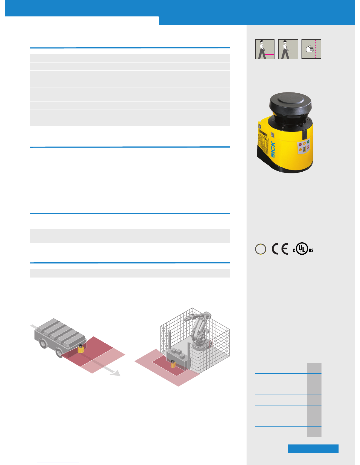
S300 Standard
Safety laser scanner
7024240
■ Extremely compact design
■ Scanning angle 270°
■ Selectable resolution
■ Certified for vertical and
horizontal use
■ 7-segment display
■ Integrated external device
monitoring (EDM)
■ Stand-by input
✓
✓
✓
IEC 61508
Compliant
Further information Page
➜ Ordering information C-58
➜ Technical specifications C-58
➜ Dimensional drawings C-59
➜ Connection diagrams C-61
➜ Accessories C-62
➜ Services A-2
Overview of technical specifications
Protective field range 2 m
Warning field range 8 m (at 30 % reflectivity)
Number of field sets 1
Scan angle 270°
Resolution 30 mm, 40 mm, 50 mm, 70 mm,
selectable
Response time 80 ms
Type Type 3 (IEC/EN 61496-3)
Safety integrity level SIL2 (IEC/EN 61508)
Product description
High-end safety at entry level price
The low-cost solution for simple require-
ments with one protective field and warning field.
Ideal for the horizontal and vertical protection of hazardous areas and areas of
access.
With adjustable object resolution as well as
configurable "contour as reference."
■ 1 protective and warning field
■ New multi-system "Configuration & Diag-
nostic Software" CDS
In-system added value
■ Supports integration with multiple safety control solutions
➜ For safety system combinations, see appendix "Sensor systems and safe control solutions
from SICK"
■ Freely moving transport vehicles
■ Production lines
■ Machining centres
■ Entry/Exit stations
■ Robot cells
■ Overhead monorail transport systems
Hazardous area protection on an AGV with one
direction of travel
Hazardous area protection on a robot cell
Applications
➜ You can find more applications using the application finder at www.sickusa.com/applications
WS/WE 12-2
Page 2

A
B
C
D
E
F
G
H
I
J
K
L
M
N
O
P
Q
R
© SICK, Inc., USA. All rights, including changes to technical specifications
and or to the equipment without prior notification, are reserved.
C - 58
S300 Standard
Safety laser scanner
7024240
Ordering information
Delivery S300
■ Safety laser scanner
■ Operating instructions and CDS (Configuration & Diagnostic Software) on CD-ROM
■ Adhesive label "important information"
The system plug has to be ordered separately!
➜ Ordering information for system plug and accessories, see page C-62
Typ e Part number
S30B-2011BA 1026820
Detailed technical specifications
General data
Laser protection class 1 (21 CFR 1040.10 und 1040.11, IEC 60825-1:2001)
Enclosure rating IP 65 (EN 60529)
Protection class 2 (DIN VDE 0160, DIN EN 50178)
Typ e Type 3 (IEC/EN 61496-3)
Safety integrity level SIL2 (IEC/EN 61508)
Ambient operating temperature from ... to –10 °C ... +50 °C
Type of lig ht Pulsed laser diode
Wave length 905 nm
Housing colour RAL 1021
Housing material Aluminium die-cast
Optics cover material Polycarbonate
Optics cover surface finish Outside with scratch-resistant coating
System plug With ESD protected configuration memory
Dimensions (W x H x D) 102 mm x 152 mm x 105 mm
Weight 1.2 kg
Functional data
Scan angle 270°
Protective field range 2 m
Reflectivity Reflectors 1.8 % ... >1000 %
Response time 80 ms
Resolution 30 mm, 40 mm, 50 mm, 70 mm, selectable
Angular resolution 0.5°
Protective field supplement 100 mm
Warning field range 8 m (at 30 % reflectivity)
Distance measuring range 30 m
Number of mulitple samplings 2 ... 16, configurable via CDS
Reset time 2 s ... 60 s, configurable
➜ Additional technical information is described in operating instructions, which are available to download at www.sickusa.com/literature
Page 3
A
B
C
D
E
F
G
H
I
J
K
L
M
N
O
P
Q
R
© SICK, Inc., USA. All rights, including changes to technical specifications
and or to the equipment without prior notification, are reserved.
C - 59
S300 Standard
Safety laser scanner
7024240
Electrical data
Connection type Plug-in connection housing with screw
Connector technology Screw-type terminals
Supply voltage V
s
24 V DC (16.8 V DC ... 30 V DC)
Power consumption 0.33 A (24 V DC)
Power consumption 1.65 A
1)
Number of inputs
EDM
Restart/Reset
Standby
1
1
1
Number of safety capable outputs
Safety outputs (OSSD)
Output for warning field
Diagnostic output
Restart/reset required
2 x 250 mA
1 x 100 mA
1 x 100 mA
1 x 100 mA
Configuration and diagnostics interface
Trans mi ssion rate
RS-232
38.4 kBaud
1)
Including maximum output load
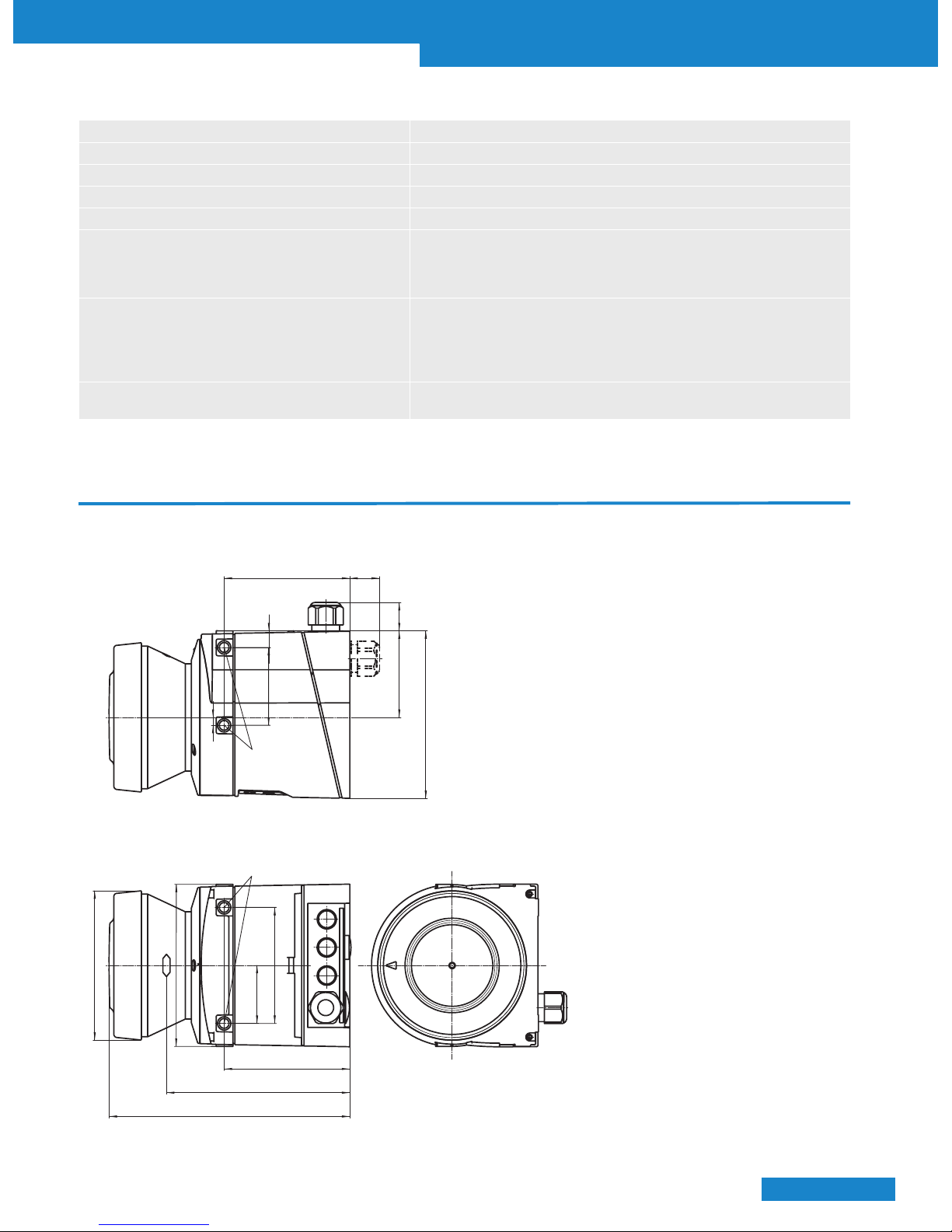
Dimensional drawings
79.3
25
M5 x 7.5
10.5
49
5
± 0.2
24
54.5
106
M5 x 7.5
Ø 94
102
79.3
116
152
36.5
73
Dimensions in mm
S300
Page 4

A
B
C
D
E
F
G
H
I
J
K
L
M
N
O
P
Q
R
© SICK, Inc., USA. All rights, including changes to technical specifications
and or to the equipment without prior notification, are reserved.
C - 60
S300 Standard
Safety laser scanner
7024240
Scan plane origin
73
130
146
270°
23.8
116
36.4
74.7
69.7
59.7
Max. 200
Min. 15 Min. 15
54.5
106
126
Dimensions in mm
Page 5

A
B
C
D
E
F
G
H
I
J
K
L
M
N
O
P
Q
R
© SICK, Inc., USA. All rights, including changes to technical specifications
and or to the equipment without prior notification, are reserved.
C - 61
S300 Standard
Safety laser scanner
7024240
Connection diagrams
➜ You can find connection diagrams at www.sickusa.com/connectiondiagrams
With restart interlock and external device monitoring
2)
■ S300 Standard in conjunction with relays/contactors
■ Operating mode: with restart interlock and external device
monitoring (EDM)
Comments
1) Output circuits: These contacts are to be connected to the
controller such that, with the output circuit open, the dangerous state is disabled. For categories 4 and 3, the integration
must be dual-channel (x/y paths). Single-channel integration
in the control (z path) is only possible with a single-channel
control and taking the risk analysis into account.
2) Functional earth (FE): To achieve the specified EMC safety,
the functional earth (FE) must be connected (e.g. to the central earth star point on the vehicle or the system).
Page 6

A
B
C
D
E
F
G
H
I
J
K
L
M
N
O
P
Q
R
© SICK, Inc., USA. All rights, including changes to technical specifications
and or to the equipment without prior notification, are reserved.
C - 62
S300 Standard
Safety laser scanner
7024240
Product group Applications
Further
information
Safety relays
Safety relays allow simple integration of safety components
into machinery or plant.
Page N-0
Safety controllers
Safety controllers are utilized when the safety function
(e.g. switching off a dangerous movement) is to be
accomplished in a flexible way by logical combination of safety
relevant signals. Operation of machinery becomes more flexible
and generation of machine variants becomes easier.
Page O-0
Safety fieldbus solutions
Safety fieldbus solutions are utilized in plants and machinery
of larger scale. This saves cabling and enables modular design
of the safety automation. Potential errors or faults can be
easily identified via the comprehensive diagnostics functions.
That significantly reduces machine down times. SICK offers
solutions for the open automation standards: AS-i Safety at
Work, DeviceNet Safety and PROFIsafe.
Safe control solutions
Accessories
Connection cable
Typ e Number of cores Cable length Part number
Connection cable 15 100 m 6030795
Mounting systems
Typ e Mounting Adjustment Note Part number
Mounting kit 1a
Mounting bracket for mounting
at the rear on wall or machine
— — 2034324
Mounting kit 1b
Mounting bracket for rear
mounting on wall or machine
with protection of optics cover
— — 2034325
Mounting kit 2
Mounting bracket
Cross-wise adjustment possible
Only in conjunction with
mounting kit 1a or 1b
2039302
Mounting kit 3 Longitudinal adjustment possible
Only in conjunction with
mounting kit 2
2039303
➜ Dimensional drawings for mounting accessories, see page C-63
System plugs
Connection type Number of cores Cable length Typ e Part number
Without cable — — SX0B-A0000G 2032807
Pre-assembled 11
5 m SX0B-B1105G 2032859
10 m SX0B-B1110G 2032860
20 m SX0B-B1120G 2032861
Page 7

A
B
C
D
E
F
G
H
I
J
K
L
M
N
O
P
Q
R
© SICK, Inc., USA. All rights, including changes to technical specifications
and or to the equipment without prior notification, are reserved.
C - 63
S300 Standard
Safety laser scanner
7024240
Dimensional drawings mounting accessories
Mounting kit 1a
73
DIN74-F5
110.2
15.9
16
21.9
49
15.7
74.7
4
37.9
Mounting kit 1b
Ø 100
48
73
109.6
4
15.9
74.7
49
15.7
16
21.9
78
102.5
110.2
DIN74-F5
Dimensions in mm
Configuration connection cables
Description Connection type Cable length Part number
For connecting the configuration connection to the PC M8 x 4, SUB-D 9-pol
2 m 6021195
8 m 2027649
Configuration software
Type Description Part number
CDS
CDS (Configuration & Diagnostic Software) on CD-ROM including online documentation
and operating instructions in all available languages
2032314
Power supply units
Input voltage Output voltage Maximum output current Part number
100 V AC, 240 V AC
24 V DC
2.1 A 7028789
3.9 A 7028790
120 V AC, 230 V AC
2.5 A 6010361
4 A 6010362
Miscellaneous
Type Description Part number
Optic cover Spare parts set for optic cover with replacement seal and screws 2039248
Plastic cleaner Plastic cleaner and care product, anti-static 5600006
Lens cloth Cloth for cleaning the front screen 4003353
Page 8

A
B
C
D
E
F
G
H
I
J
K
L
M
N
O
P
Q
R
© SICK, Inc., USA. All rights, including changes to technical specifications
and or to the equipment without prior notification, are reserved.
C - 64
S300 Standard
Safety laser scanner
7024240
Mounting kit 2
31.7
33.4
18
19.7
19.7
18
4
78.2
40.7
139.4
130
118.5
Mounting kit 3
158.8
150
130
5
20.5
41
Dimensions in mm
 Loading...