

Page 1
OPERATING INSTRUCTIO
NS
S300
Safety laser scanner
en
Page 2

Operating instructions
S300
This document is protected by the law of copyright, whereby all rights established therein remain with the
company SICK AG. Reproduction of this document or parts of this document is only permissible within the limits
of the legal determination of Copyright Law. Alteration or abridgement of the document is not permitted without
the explicit written approval of the company SICK AG.
2 © SICK AG • Industrial Safety Systems • Germany • All rights reserved 8010948/YY96/2016-02-17
Subject to change without notice
Page 3

Operating instructions
S300
Contents
Contents
1 About this document.........................................................................................................7
1.1 Function of this document....................................................................................7
1.2 Target group ..........................................................................................................7
1.3 Scope ..................................................................................................................... 7
1.4 Depth of information............................................................................................. 8
1.5 Abbreviations used ............................................................................................... 8
1.6 Symbols used ........................................................................................................9
2 On safety...........................................................................................................................10
2.1 Qualified safety personnel..................................................................................10
2.2 Applications of the device...................................................................................10
2.3 Correct use ..........................................................................................................11
2.4 General safety notes and protective measures ................................................11
2.5 Environmental protection ...................................................................................13
2.5.1 Disposal .............................................................................................13
2.5.2 Separation of materials ....................................................................13
2.6 Applicable directives and standards..................................................................14
3 Product description.........................................................................................................15
3.1 Special features ..................................................................................................15
3.2 Function...............................................................................................................16
3.2.1 Principle of operation........................................................................16
3.2.2 Field set comprising of protective field and warning field(s)..........18
3.2.3 Monitoring cases...............................................................................19
3.3 S300 variants......................................................................................................20
3.3.1 Device components ..........................................................................20
3.3.2 Functions of the S300 variants........................................................20
3.3.3 Applications.......................................................................................22
3.4 Status indicators .................................................................................................24
3.4.1 LEDs and 7<segment display............................................................24
3.5 Interoperability ....................................................................................................25
3.5.1 Examples for EFI systems.................................................................26
3.5.2 Interoperability of the variants .........................................................27
3.5.3 Specific features with EFI systems...................................................28
3.5.4 Interoperability with sens:Control devices.......................................28
4 Configurable functions ...................................................................................................29
4.1 Compatibility mode .............................................................................................29
4.2 System parameters.............................................................................................32
4.2.1 Application name ..............................................................................32
4.2.2 Name of the scanner ........................................................................32
4.2.3 User data ...........................................................................................32
4.2.4 Display direction of the 7<segment display......................................32
4.3 Application...........................................................................................................33
4.3.1 Resolution..........................................................................................34
4.3.2 Basic response time .........................................................................34
4.3.3 Maximum protective field range.......................................................34
4.4 Incremental encoder...........................................................................................35
4.4.1 Pulses per cm travel that are output by the incremental
encoders............................................................................................35
4.4.2 Tolerances allowed on the dynamic inputs .....................................36
8010948/YY96/2016-02-17 © SICK AG • Industrial Safety Systems • Germany • All rights reserved 3
Subject to change without notice
Page 4

Contents
S300
4.5 Inputs .................................................................................................................. 37
4.5.1 Input delay ........................................................................................ 38
4.5.2 Sampling for the static control inputs ............................................. 38
4.6 OSSDs ................................................................................................................. 39
4.6.1 External device monitoring (EDM) ...................................................39
4.7 Restart................................................................................................................. 40
4.8 Universal I/O connections.................................................................................. 42
4.8.1 Application diagnostic output in the compatibility mode ...............43
4.9 Field sets............................................................................................................. 43
.9.1 Configuring the protective field and warning field.......................... 43
4
4.9.2 Protective field or warning field suggested by the safety
laser scanner ....................................................................................45
4.9.3 Using the contour as a reference ....................................................46
4.10 Monitoring cases ................................................................................................ 47
4.10.1 Monitoring case switching via static input information.................. 48
4.10.2 Monitoring case switching via velocity information........................ 51
4.10.3 Velocity routing via EFI .....................................................................52
4.10.4 Multiple sampling .............................................................................53
4.10.5 Checking of the monitoring case switching ....................................54
4.10.6 Park/stand-by mode......................................................................... 54
4.11 Measured data output........................................................................................55
Operating instructions
5 Mounting.......................................................................................................................... 56
5.1 Stationary application in horizontal operation.................................................. 57
5.1.1 Protective field size ..........................................................................57
5.2 Stationary vertical operation for access protection.......................................... 61
5.2.1 Minimum distance............................................................................ 61
5.3 Stationary vertical operation for hazardous point protection ..........................63
5.3.1 Minimum distance............................................................................ 63
5.4 Mobile applications ............................................................................................ 64
5.4.1 Protective field length.......................................................................65
5.4.2 Protective field width........................................................................ 68
5.4.3 Height of the scan plane .................................................................. 68
5.5 Methods of preventing unprotected areas........................................................69
5.5.1 Near range ........................................................................................ 70
5.6 Time for monitoring case switching................................................................... 71
5.7 Mounting steps ................................................................................................... 73
5.7.1 Direct mounting ................................................................................74
5.7.2 Mounting with mounting kit 1a or 1b.............................................. 75
5.7.3 Mounting with mounting kit 2 and 3 ...............................................76
5.7.4 Information label Important information......................................... 76
5.7.5 Using multiple S300 safety laser scanners ....................................77
6 Electrical installation .....................................................................................................79
6.1 System connection .............................................................................................81
6.1.1 Pin assignment on the system plug.................................................82
6.2 System plug assembly........................................................................................ 84
6.3 Pre-assembled system plugs ............................................................................. 86
6.4 Configuration connection M8× 4 (serial interface) ..........................................87
4 © SICK AG • Industrial Safety Systems • Germany • All rights reserved 8010948/YY96/2016-02-17
Subject to change without notice
Page 5

Operating instructions
S300
Contents
7 Application examples and connection diagrams ........................................................88
7.1 Stationary applications .......................................................................................88
7.1.1 Applications with one monitored area (S300 Standard) ................88
.1.2 Applications with multiple monitored areas
7
(S300 Advanced) ..............................................................................89
7.2 Mobile applications.............................................................................................89
7.2.1 Vehicle monitoring for unidirectional travel (S300 Standard)........89
7.2.2 Velocity-dependent vehicle monitoring for unidirectional
travel (S300 Professional)................................................................90
7.2.3 Velocity-dependent vehicle monitoring for bi-directional
travel (2 × S300 Professional in host/guest operation).................90
7.2.4 Vehicle monitoring with four safety laser scanners and the
Flexi Soft modular safety controller .................................................91
7.3 Connection diagrams..........................................................................................92
7.3.1 Restart interlock and external device monitoring ...........................92
7.3.2 Protective field switching with a static input pair............................93
7.3.3 Protective field switching with two static input pairs ......................93
7.3.4 Protective field switching with static and dynamic inputs ..............94
7.3.5 Protective field switching between two S300 with dynamic
and static inputs ...............................................................................94
7.3.6 Protective field switching between two S300 with static
inputs .................................................................................................95
7.3.7 Protective field switching between an S3000 and an S300
with static and dynamic inputs.........................................................96
7.3.8 Protective field switching with a Flexi Soft safety controller...........96
8 Configuration ...................................................................................................................97
8.1 Default delivery status........................................................................................97
8.2 Preparation of the configuration ........................................................................98
9 Commissioning ................................................................................................................99
9.1 Initial commissioning ..........................................................................................99
9.1.1 Power-up sequence...........................................................................99
9.2 Test notes ......................................................................................................... 100
9.2.1 Pre-commissioning tests................................................................ 100
9.2.2 Regular inspection of the protective device by qualified
safety personnel............................................................................. 100
9.2.3 Daily testing of the protective device by a specialist or
authorized personnel..................................................................... 101
9.3 Re-commissioning............................................................................................ 102
10 Maintenance and care................................................................................................. 103
10.1 Cleaning optics cover....................................................................................... 103
10.2 Replacing the optics cover ..............................................................................104
10.3 Replacing the device........................................................................................ 106
11 Diagnostics ................................................................................................................... 107
11.1 In the event of faults or errors......................................................................... 107
11.2 SICK support..................................................................................................... 107
11.3 Error and status indications on the LEDs....................................................... 108
11.4 Error and status indications on the 7<segment display................................. 110
11.5 Extended diagnostics....................................................................................... 115
8010948/YY96/2016-02-17 © SICK AG • Industrial Safety Systems • Germany • All rights reserved 5
Subject to change without notice
Page 6

Contents
S300
Operating instructions
12 Technical specifications ..............................................................................................116
12.1 Characteristics..................................................................................................116
12.2 OSSD response times.......................................................................................117
2.3 Timing behavior of the OSSDs .........................................................................118
1
12.4 Data sheet.........................................................................................................120
12.5 EFI status information and control commands...............................................129
12.6 Dimensional drawings ......................................................................................132
12.6.1 S300................................................................................................132
12.6.2 Mounting kits ..................................................................................132
12.6.3 Scan plane origin ............................................................................134
13 Ordering information ....................................................................................................135
13.1 Items supplied S300 ........................................................................................135
13.2 Available systems .............................................................................................135
13.3 Accessories/spare parts ..................................................................................135
13.3.1 Mounting kits ..................................................................................135
13.3.2 System plug S300 ..........................................................................136
13.3.3 Service cables.................................................................................136
13.3.4 Self assembly connecting cables ..................................................137
13.3.5 Documentation ...............................................................................137
13.3.6 Safety relays/compact safety controller .......................................137
13.3.7 Safety controllers............................................................................137
13.3.8 Network solutions...........................................................................138
13.3.9 Miscellaneous.................................................................................138
14 Annex..............................................................................................................................139
14.1 Compliance with EU directives.........................................................................139
14.2 Checklist for the manufacturer........................................................................140
14.3 Glossary.............................................................................................................141
14.4 List of tables .....................................................................................................143
14.5 List of illustrations ............................................................................................145
6 © SICK AG • Industrial Safety Systems • Germany • All rights reserved 8010948/YY96/2016-02-17
Subject to change without notice
Page 7

Operating instructions Chapter 1
S300
About this document
1 About this document
lease read this chapter carefully before working with this documentation and the S300.
P
1.1 Function of this document
These operating instructions are designed to address the technical personnel of the
machine manufacturer or the machine operator in regards to correct mounting, electrical
installation, commissioning, operation and maintenance of the S300 safety laser scanner.
These operating instructions do not provide instructions for operating the machine, the
system or the vehicle on which the safety laser scanner is, or will be, integrated. Information on this is to be found in the appropriate operating instructions for the machine, the
system or the vehicle.
1.2 Target group
These operating instructions are addressed to planning engineers, machine designers and
the operators of machines and systems which are to be protected by one or several S300
safety laser scanners. They also address people who integrate the S300 into a machine, a
system or a vehicle, initialize its use, or who are in charge of servicing and maintaining the
device.
1.3 Scope
These operating instructions are original operating instructions.
These operating instructions are only applicable to the S300 safety laser scanner with one
of the following entries on the type label in the field Operating Instructions:
8010946 AE W284
8010946 AE X175
8010946 AE XK33
8010946 AE YY96
This document is part of SICK part number 8010946 (operating instructions “S300 —
Safety laser scanner” in all available languages).
For the configuration and diagnostics of these devices you require a CDS (Configuration &
Diagnostic Software) version M 3.6.7. To determine the version of your software version,
select the Module-Info... option in the ? menu.
8010948/YY96/2016-02-17 © SICK AG • Industrial Safety Systems • Germany • All rights reserved 7
Subject to change without notice
Page 8

Chapter 1 Operating instructions
S300
About this document
1.4 Depth of information
hese operating instructions contain information on the S300 safety laser scanner. They
T
have the following parts:
Note
mounting
electrical installation
commissioning and configuration
care and maintenance
Planning and using protective devices such as the S300 also require specific technical
skills which are not detailed in this documentation.
General information on accident prevention using opto-electronic protective devices can
be found in the competence brochure “Guidelines Safe Machinery”.
When operating the S300, the national, local and statutory rules and regulations must be
observed.
Please refer also to the SICK AG homepage on the Internet at www.sick.com
Here you will find information on:
application examples
these operating instructions in different languages for viewing and printing
fault diagnosis and troubleshooting
part numbers
accessories
conformity and approval
AGV
ANSI
AWG
CDS
CMS
EDM
EFI
EMC
ESD
ESPE
FPLC
OSSD
RIA
1.5 Abbreviations used
Automated Guided Vehicle
American National Standards Institute
American Wire Gauge = standardization and classification of wires and cables by type,
diameter etc.
SICK Configuration & Diagnostic Software = software for configuration and diagnostics on
the S300
Contour Measurement & Safety = expanded measured data output as well as detection of
reflectors as artificial landmarks
External device monitoring
Enhanced function interface = safe SICK device communication
Electromagnetic compatibility
Electrostatic discharge
Electro-sensitive protective equipment
Fail-safe programmable logic controller
Output signal switching device = signal output of the protective device that is used to stop
the dangerous movement
Robotic Industries Association
8 © SICK AG • Industrial Safety Systems • Germany • All rights reserved 8010948/YY96/2016-02-17
Subject to change without notice
Page 9

Operating instructions Chapter 1
S300
About this document
1.6 Symbols used
ecommendations are designed to give you some assistance in your decision-making
Recommendation
Note
, ,
R
process with respect to a certain function or a technical measure.
Refer to notes for special features of the device.
Display indicators show the status of the 7<segment display on the S300:
Flashing indication of characters, e.g. 8
Alternating indication of characters, e.g. L and 2
LED symbols describe the status of an LED:
Constant indication of characters, e.g. 8
The “OSSDs in the OFF state” LED is illuminated continuously.
The “Error/contamination” LED is flashing.
The “Warning field interrupted” LED is off.
Take action …
WARNING
Instructions for taking action are shown by an arrow. Read carefully and follow the
instructions for action.
Warning!
A warning indicates an actual or potential risk or health hazard. Observation and implementation of the warning will protect you from accidents.
Read carefully and follow the warning notices!
Information is displayed in the software indicating to you which settings you can make in
the CDS (Configuration & Diagnostic Software).
The term “dangerous state”
The dangerous state (standard term) of the machine is always shown in the drawings and
diagrams of this document as a movement of a machine part. In practical operation, there
may be a number of different dangerous states:
machine movements
vehicle movements
electrical conductors
visible or invisible radiation
a combination of several risks and hazards
8010948/YY96/2016-02-17 © SICK AG • Industrial Safety Systems • Germany • All rights reserved 9
Subject to change without notice
Page 10

Chapter 2 Operating instructions
S300
On safety
2 On safety
his chapter deals with your own safety and the safety of the system operators.
T
Please read this chapter carefully before working with the S300 or with the machine
protected by the S300.
2.1 Qualified safety personnel
The S300 safety laser scanner must be installed, connected, commissioned and serviced
only by qualified safety personnel. Qualified safety personnel are defined as persons who
due to their specialist training and experience have adequate knowledge of the power-
driven equipment to be checked
and
have been instructed by the responsible machine owner in the operation of the machine
and the current valid safety guidelines
and
are sufficiently familiar with the applicable official health and safety regulations, direc-
tives and generally recognized engineering practice (e.g. DIN standards, VDE stipula-
tions, engineering regulations from other EU member states) that they can assess the
work safety aspects of the power-driven equipment
and
have access to these operating instructions and have read them.
As a rule these are qualified safety personnel from the ESPE manufacturer or also those
persons who have been appropriately trained at the ESPE manufacturer, are primarily
involved in checking ESPE and are allocated the task by the organization operating the
ESPE.
Note
2.2 Applications of the device
The S300 safety laser scanner is used to protect persons and systems. It is intended to be
used to monitor hazardous areas indoors.
It is not allowed to use the S300 outdoors.
The S300 cannot provide protection from parts thrown out of the machine or emitted
radiation.
The S300 complies with the requirements in the standard on the radiated emissions as
defined for class A (industrial application); the S300 is therefore only suitable for use in an
industrial environment.
The device is a type 3 ESPE as defined by IEC 61496<1 and IEC 61496<3 and is therefore
allowed for use with category 3 PL d controls as per EN ISO 13849<1 or SIL2 as per
IEC 61508.
The S300 is suitable for:
hazardous area protection
hazardous point protection
access protection
vehicle protection (electrically powered industrial trucks)
Depending on the application, other protective devices and measures may be required in
addition to the safety laser scanner.
10 © SICK AG • Industrial Safety Systems • Germany • All rights reserved 8010948/YY96/2016-02-17
Subject to change without notice
Page 11
Operating instructions Chapter 2
S300
On safety
2.3 Correct use
he S300 safety laser scanner must be used only as defined in section 2.2 “Applications
T
of the device” on page 10. It must be used only by qualified personnel and only on the
machine where it has been installed and initialized by qualified safety personnel in accor-
dance with these operating instructions. It is only permitted to be used on machines on
which the dangerous state can be stopped immediately by the S300 and/or it is possible
to prevent the machine being placed in operation.
Note
If the device is used for any other purposes or modified in any way — also during mounting
and installation — any warranty claim against SICK AG shall become void.
2.4 General safety notes and protective measures
Pay attention to the safety notes!
WARNING
Please observe the following items in order to ensure the correct use of the S300 safety
laser scanner.
Repair only by authorized persons!
The improper repair of the protective device can result in the loss of the protective function. The protective device is only allowed to be repaired by the manufacturer or persons
authorized by the manufacturer.
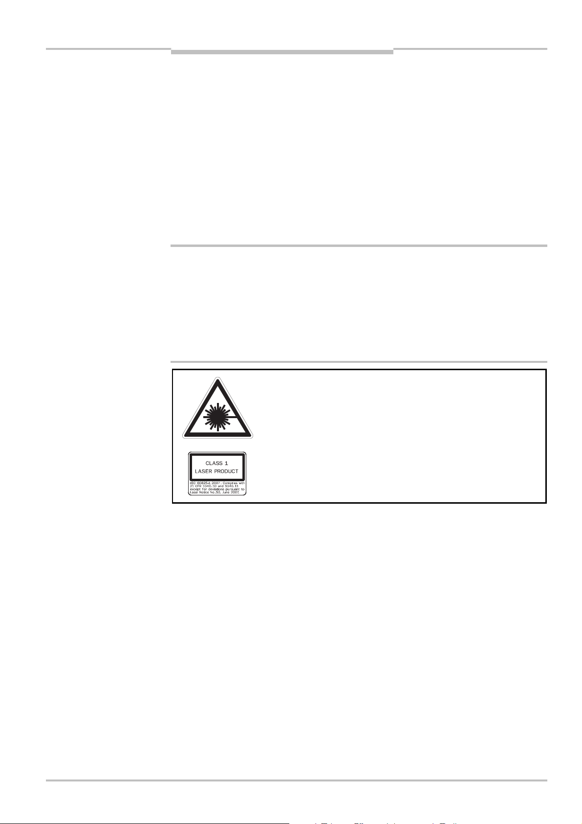
The S300 safety laser scanner is of laser safety class 1.
Additional measures for screening the laser radiation are not
necessary (eye safe).
This device meets the norms: IEC 60825<1 as well as CDRH 21 CFR 1040.10 and
1040.11; excluded are deviations due to Laser Notice No. 50, dated 24.06.2007. In the
standards CDRH 21 CFR 1040.10 and 1040.11 the following note is required: “Caution
— use of controls, adjustments or performance of procedures other than those herein
specified may result in hazardous radiation exposure!”
During the mounting, installation and usage of the S300, observe the standards and
directives applicable in your country. You will find an overview of the most important
regulations in section 2.6 “Applicable directives and standards” on page 14.
The national/international rules and regulations apply to the installation, commissioning,
use and periodic technical inspections of the S300 safety laser scanner, in particular:
– Machinery Directive
– Work Equipment Directive
– the work safety regulations/safety rules
– other relevant safety regulations
Manufacturers and operators of the machine on which the S300 is used are responsible
for obtaining and observing all applicable safety regulations and rules.
8010948/YY96/2016-02-17 © SICK AG • Industrial Safety Systems • Germany • All rights reserved 11
Subject to change without notice
Page 12

Chapter 2 Operating instructions
S300
On safety
The notes, in particular the test notes (see chapter 9 “Commissioning” on page 99) in
these operating instructions (e.g. on use, mounting, installation or integration into the
machine control) must be observed.
Changes to the configuration of the devices can degrade the protective function. After
every change to the configuration you must therefore check the effectiveness of the
protective device. The person who makes the change is also responsible for the correct
protective function of the device. When making configuration changes, please always
use the password hierarchy provided by SICK to ensure that only authorized persons
make changes to the configuration. The SICK service team is available to provide assis-
tance if required.
The tests must be carried out by qualified safety personnel or specially qualified and
authorized personnel and must be recorded and documented to ensure that the tests
can be reconstructed and retraced at any time.
The operating instructions must be made available to the operator of the machine where
the S300 is used. The machine operator is to be instructed in the use of the device by
qualified safety personnel and must be instructed to read the operating instructions.
To meet the requirements of the relevant product standards (e.g. IEC 61496<1), the ex-
ternal voltage supply for the devices (SELV) must be able to bridge a brief mains failure
of 20 ms. Power supplies according to EN 60204<1 satisfy this requirement. Suitable
power supplies are available as accessories from SICK (see section 13.3 “Accessories/spare parts” on page 138).
In case of data cables more than 30 m long, as per EN 61000 either the device itself
must be earthed, or the screen on the data cable must be earthed in the immediate
vicinity of the cable entry in the system plugs.
Enclosed with these operating instructions is a checklist for checking by the manufactu-
rer and OEM (see section 14.2 “Checklist for the manufacturer” on page 140). Use this
checklist when checking the system that is protected with the S300.
12 © SICK AG • Industrial Safety Systems • Germany • All rights reserved 8010948/YY96/2016-02-17
Subject to change without notice
Page 13

Operating instructions Chapter 2
Tab.1:
Overview on disposal
S300
On safety
2.5 Environmental protection
he S300 safety laser scanner is constructed in such a way that it adversely affects the
T
environment as little as possible and uses only a minimum of power and natural
resources.
At work, always act in an environmentally responsible manner.
2.5.1 Disposal
Unusable or irreparable devices should always be disposed as per the applicable national
regulations on waste disposal (e.g. European waste code 16 02 14).
Notes
WARNING
We would be pleased to be of assistance to you on the disposal of these devices.
Contact your local SICK representative.
Information on the individual materials in the S300 is given in chapter 12 “Technical
specifications” on page 120.
2.5.2 Separation of materials
Only qualified safety personnel are allowed to separate materials!
Caution is required when dismantling devices. There is a risk of injuries.
Before you send the devices for appropriate recycling, it is necessary to separate the diffe-
rent materials in the S300.
Separate the housing from the rest of the parts (in particular the circuit boards).
Send the separated parts for recycling as appropriate (see Tab. 1).
by components
Components Disposal
Product
Housing Metal recycling (aluminium)
Motor bracket Metal recycling (zinc die-cast housing)
Optics cover Plastic recycling
Circuit boards, cables, connectors and
electrical connecting pieces
Packaging
Cardboard, paper Paper/cardboard recycling
Polyethylene packaging Plastic recycling
Electronic recycling
8010948/YY96/2016-02-17 © SICK AG • Industrial Safety Systems • Germany • All rights reserved 13
Subject to change without notice
Page 14

Chapter 2 Operating instructions
S300
On safety
2.6 Applicable directives and standards
he most important directives and standards, valid for the use of opto-electronic protective
T
devices in Europe, are listed below. Further regulations may be of importance to you,
depending on the application. You can obtain further information of machine-specific
standards from national institutions (e.g. DIN, BSI, AFNOR etc.), the authorities or your
trade association.
If you operate the machine or vehicle in a country outside the European Union, please
contact the manufacturer of the system and the local authorities and obtain information
on the regulations and standards applicable there.
Application and installation of protective devices
Machinery Directive, e.g.:
Safety of machinery — Basic concepts, general principles for design (EN ISO 12100)
Industrial automation systems — Safety of integrated manufacturing systems — Basic
requirements (ISO 11161)
Safety of machinery — Electrical equipment of machines — Part 1: General requirements
(IEC 60204/EN 60204)
Safety of machinery — safety distances to prevent hazard zones being reached by the
upper and lower limbs (EN ISO 13857)
Safety requirements for robots (EN ISO 10218<1)
Safety of industrial trucks. Driverless trucks and their systems (EN 1525)
Safety of machinery — The positioning of protective equipment in respect of approach
speeds of parts of the human body (EN ISO 13855)
Safety of machinery — Principles for risk assessment (EN ISO 14121<1)
Safety of machinery — Safety-related parts of control systems — Part 1: General
principles for design (EN ISO 13849<1) as well as part 2: Validation (EN ISO 13849<2)
Safety of machinery — electro-sensitive protective equipment — Part 1: General
requirements (IEC 61496<1) as well as part 3: Special requirements for AOPDDR
(IEC 61496<3)
Safety of machinery — Application of protective equipment to detect the presence of
persons (IEC/TS 62046)
Foreign standards, for example:
Performance Criteria for Safeguarding (ANSI B11.19)
Machine tools for manufacturing systems/cells (ANSI B11.20)
Safety requirements for Industrial Robots and Robot Systems (ANSI/RIA R15.06)
Safety Standard for guided industrial vehicles and automated functions of named
industrial vehicles (ANSI B56.5)
Note
Recommendation
To some extent these standards require the protective device to have the safety level
Control reliable. The S300 safety laser scanner meets this requirement.
Please request our competence brochure “Guidelines Safe Machinery” on this subject
(part no. 8007988).
14 © SICK AG • Industrial Safety Systems • Germany • All rights reserved 8010948/YY96/2016-02-17
Subject to change without notice
Page 15

Operating instructions Chapter 3
S300
Product description
3 Product description
his chapter provides information on the special features and properties of the S300
T
safety laser scanner. It describes the construction and the operating principle of the
device.
3.1 Special features
270° scan area
increased dust and particle tolerance due to dazzle and particle algorithms
variants with scanning ranges up to 2 m or 3 m (maximum protective field radii)
configuration using PC or notebook with SICK Configuration & Diagnostic Software
configuration memory in the system plug. In case of device replacement, the existing
configuration is automatically transferred to the S300 newly connected. In this way
downtimes can be significantly reduced.
field sets comprising of one protective field and up to two warning fields
contour monitoring of the protective field if only one warning field is used
5 universal I/O connections
integrated external device monitoring (EDM)
integrated restart interlock/restart interlock delay for which the parameters can be set
safe bus interface via enhanced function interface (EFI) for operation in a system with
other safety laser scanners, with products of the sens:Control product group or with a
Flexi Soft safety controller
compatibility mode for interoperability with safety laser scanners of an older generation
From S300 Advanced
up to 4 field sets
protective field switching via static inputs or EFI
S300 Professional
up to 8 field sets
protective field switching via dynamic inputs using incremental encoders
velocity routing using a Flexi Soft safety controller
S300 Expert
up to 16 field sets
CMS function for the detection of reflectors as artificial landmarks
8010948/YY96/2016-02-17 © SICK AG • Industrial Safety Systems • Germany • All rights reserved 15
Subject to change without notice
Page 16
Chapter 3 Operating instructions
Fig.1:
Principle of operation,
Send pulses
Rec
eive pulse
Send pulse
S300
Receive pulses
S300
Product description
3.2 Function
he S300 safety laser scanner operates correctly as a protective device only if the
T
following conditions are met:
The control of the machine, system or vehicle must be electrical.
It must be possible to transfer the dangerous state of the machine, the system or the
vehicle to a safe state at any time using the OSSDs on the S300, i.e. before a person
has reached the hazardous point or hazardous area.
Or:
It must be possible to transfer the dangerous state of the machine, the system or the
vehicle to a safe state at any time using the OSSDs on a safety controller connected to
the S300 or to a further safety laser scanner.
The S300 must be mounted and configured such that it detects objects as they enter
the hazardous area (see chapter 5 “Mounting” on page 56 and chapter 9 “Commissioning” on page 99).
The safety laser scanner’s optical path must always remain clear and is not allowed to
be covered by transparent objects such as protective windows, Plexiglas, lenses etc. The
safety laser scanner’s protective function can only be ensured if the contamination measurement function is not bypassed by such measures.
time-of-flight measurement
by the S300
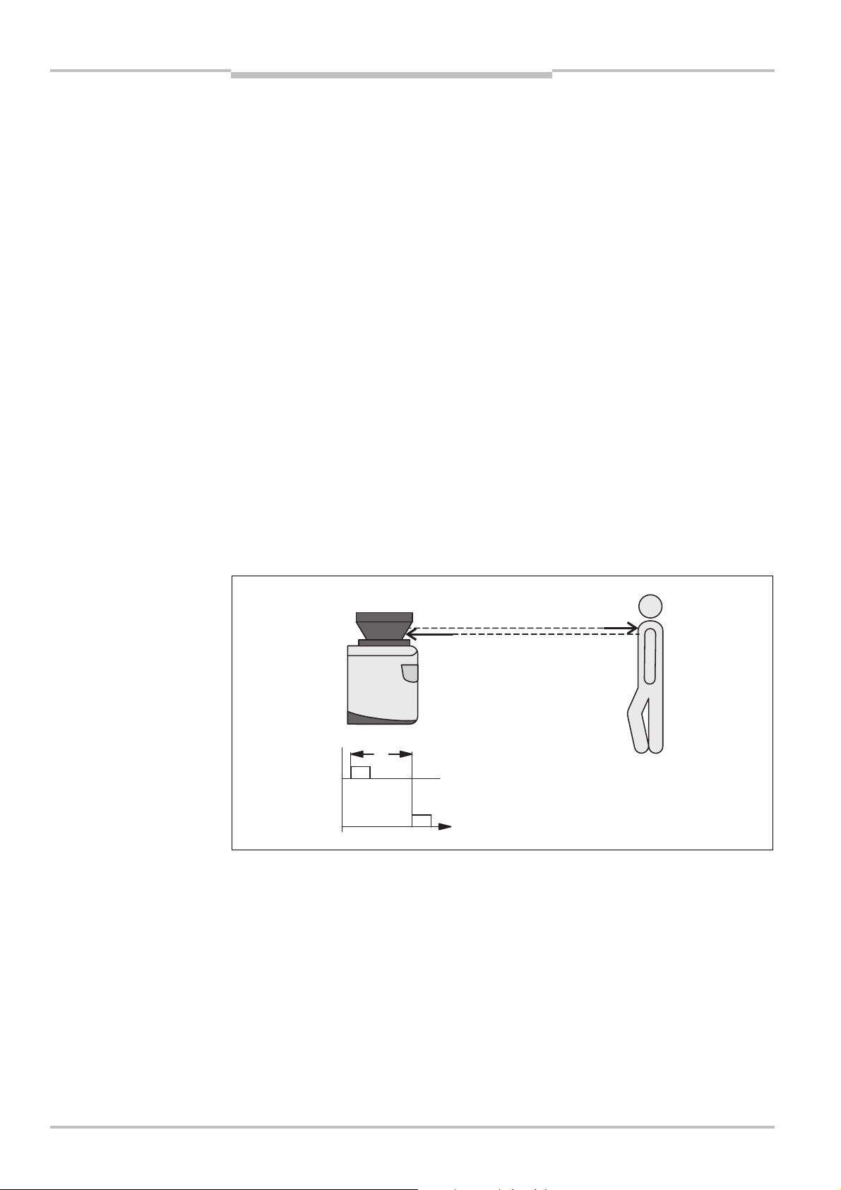
3.2.1 Principle of operation
The S300 is an optical sensor that scans its surroundings in two dimensions using infrared
laser beams. It is used to monitor hazardous areas on machines or vehicles.
t
The S300 works on the principle of time-of-flight measurement. It sends out very short
pulses of light (send pulses). At the same time an “electronic stopwatch” is started. When
the light hits an object, it is reflected and received by the safety laser scanner (receive pulses). From the time between sending and reception (t) the S300 calculates the distance
to the object.
16 © SICK AG • Industrial Safety Systems • Germany • All rights reserved 8010948/YY96/2016-02-17
Subject to change without notice
Page 17
Operating instructions Chapter 3
Fig.2:
Principle of operation,
–
45°0°225°
90°
S300
rotation of the S300
Product description
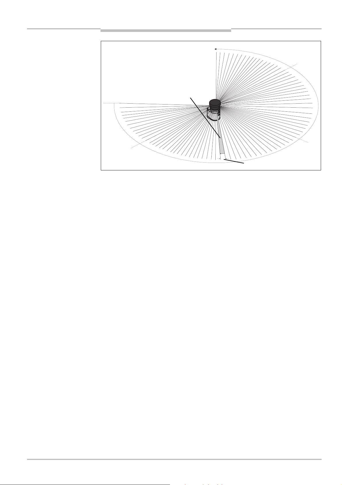
In the S300 there is also a mirror rotating at constant speed that deflects the light pulses
such that they cover an arc of 270°. In this way an object can be detected in the protective field within 270°. The first beam of a scan starts at –45° relative to the back of the
safety laser scanner.
The S300 sends a pulse of light with an angular resolution of 0.5° . As a result resolu-
tions between 30 mm and 150 mm can be achieved .
Due to its active scanning principle, the S300 does not require receivers or reflectors. This
has the following advantages:
Your installation effort is lower.
You can easily adapt the monitored area to the hazardous area on a machine.
In comparison with contact sensors, electro-sensitive scanning is nearly wear-free.
8010948/YY96/2016-02-17 © SICK AG • Industrial Safety Systems • Germany • All rights reserved 17
Subject to change without notice
Page 18
Chapter 3 Operating instructions
Fig.3:
Field set with one
Warning
Warning
Protective
S300
Product description
3.2.2 Field set comprising of protective field and warning field(s)
Protective fields and warning fields form the so-called field set. You can configure these
field sets with the aid of the CDS. The fields can be configured as circular, rectangular or of
rbitrary shape. If the area to be monitored changes, then you can re-configure the S300
a
in software without additional mounting effort.
Depending on the variant used (see section 3.3.2 “Functions of the S300 variants” on
page 20), you can define up to 16 field sets and save these in the safety laser scanner. In
this way you can switch to a different field set in case of a change in the monitoring situation (see section 3.2.3 “Monitoring cases” on page 19).
You can configure field sets comprising one protective field and one or two warning fields.
The protective field secures the hazardous area on a machine or vehicle. As soon as the
safety laser scanner detects an object in the protective field, the S300 switches the
OSSDs to the off status and thus initiates the shutdown of the machine or stop of the
vehicle.
protective field and two
warning fields
field
Note
field 1
field 2
You can define the warning fields such that the safety laser scanner detects an object
before the actual hazardous area.
Warning field 1 can be used in particular for vehicle protection to detect an object even
before the actual hazardous area and to slowly retard the movement of the vehicle or bring
it to a standstill. In this way the wear on the brakes on an AGV can be reduced. Warning
field 2 can also be used to trigger a warning signal.
A warning field on all S300 variants is not allowed to be used for tasks related to the
protection of people.
Contour monitoring
In addition to the protective field, the S300 can also monitor a contour (e.g. the floor in
vertical applications).
18 © SICK AG • Industrial Safety Systems • Germany • All rights reserved 8010948/YY96/2016-02-17
Subject to change without notice
Page 19
Operating instructions Chapter 3
Fig.4:
S300
Remote with
Field set 2 with larger
Field set 1
Monitoring case 2
Monitoring case 1
S300
Product description
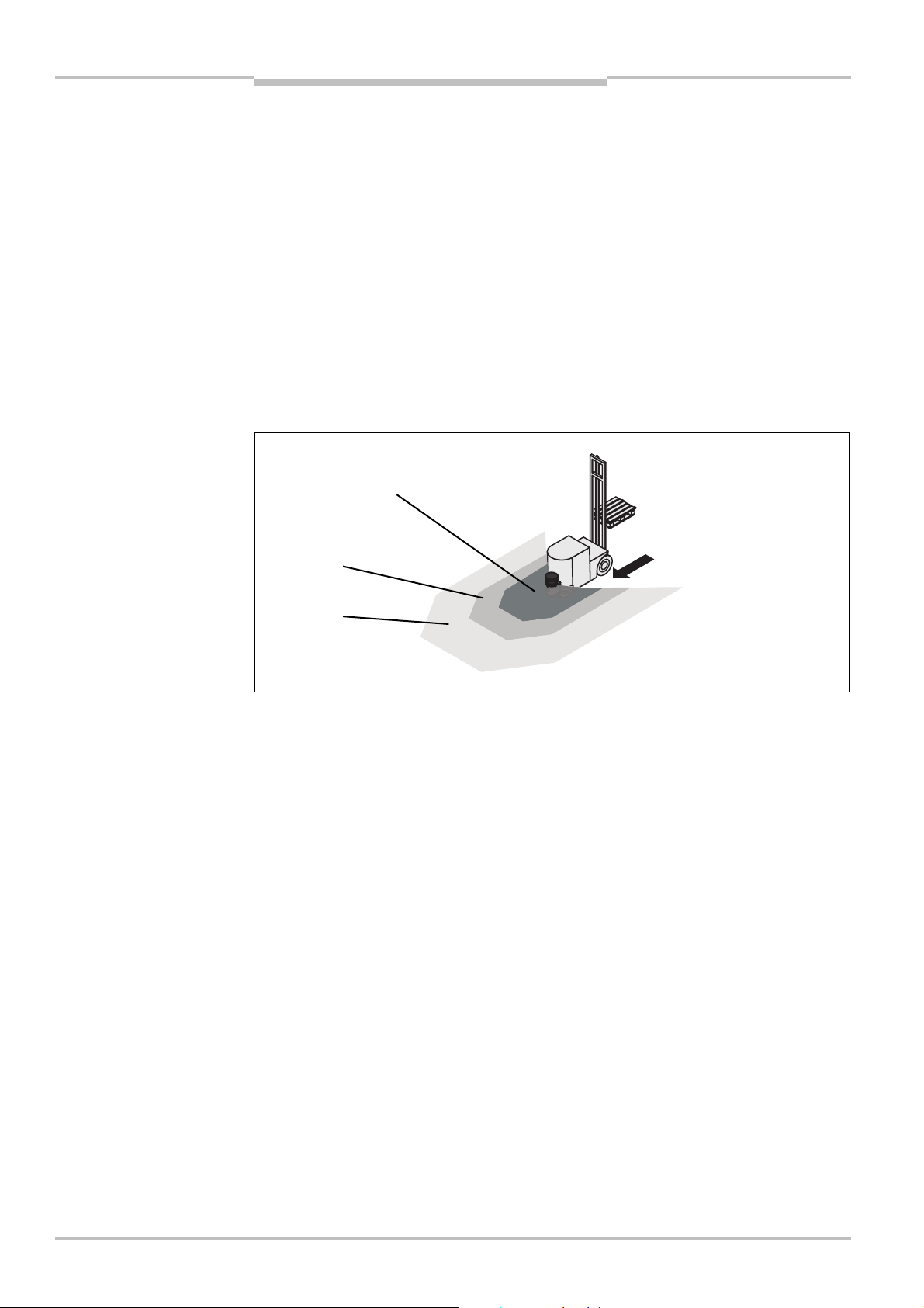
3.2.3 Monitoring cases
Depending on the variant used (see section “Functions of the S300 variants” on page 20)
up to 32 monitoring cases can be defined and selected during operation using local static
r dynamic control inputs or via EFI. In this way process-dependent hazardous area pro-
o
tection or velocity-dependent vehicle monitoring is possible for example.
two monitoring cases on an
AGV
Low velocity
High velocity
protective and warning fields
8010948/YY96/2016-02-17 © SICK AG • Industrial Safety Systems • Germany • All rights reserved 19
Subject to change without notice
Page 20
Chapter 3 Operating instructions
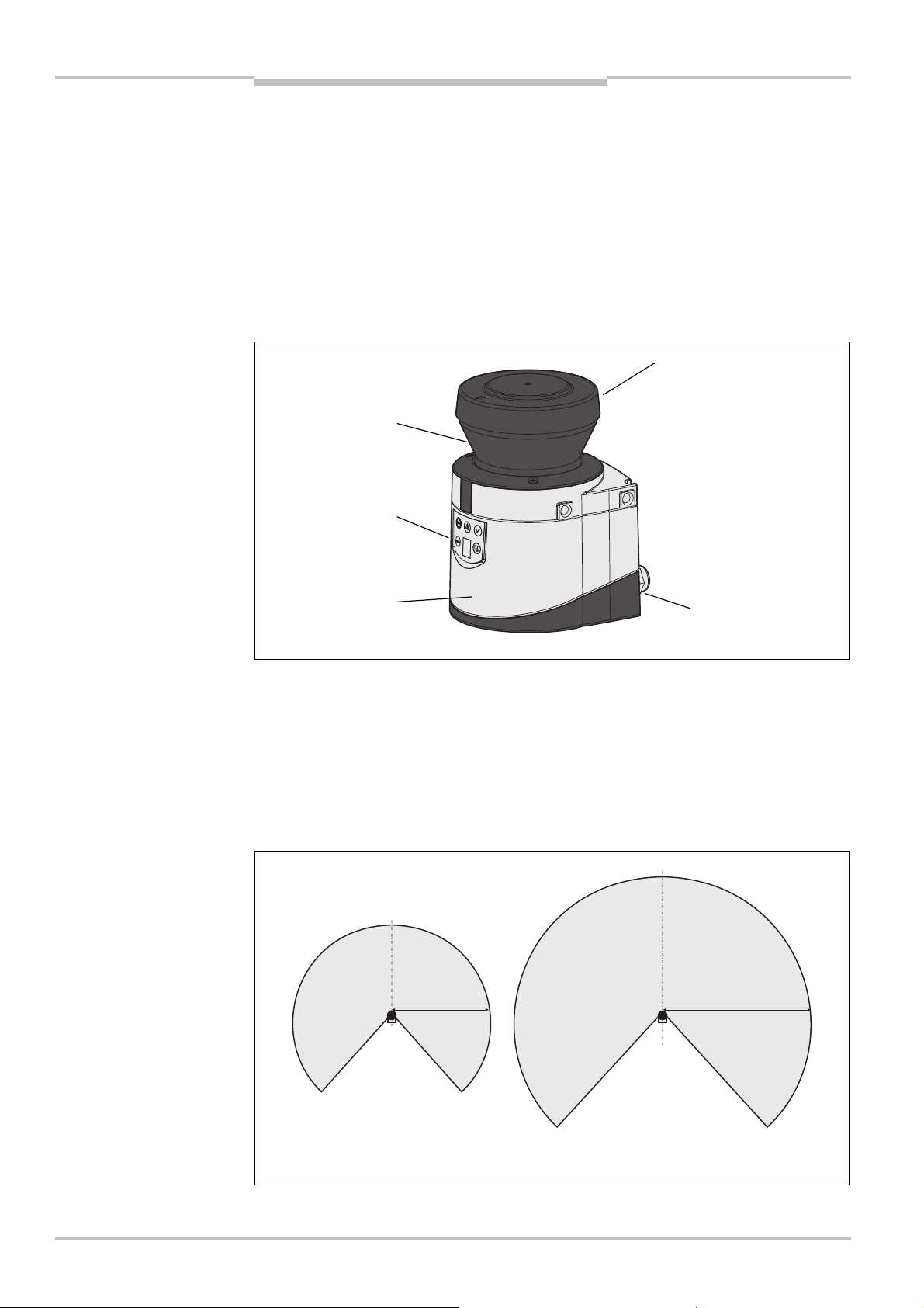
Fig.5:
Device components
Fig.6:
Protective field ranges
Optics cover
System plug
Sensor
LEDs and
display
Window for
Long Range
Medium Range
Max. 3
m
Max. 2
m
S300
Product description
3.3 S300 variants
3.3.1 Device components
The S300 safety laser scanner comprises three components:
the sensor with the opto-electronic acquisition system, the LEDs and the 7<segment
display
the optics cover with the window for the light output
the system plug with the configuration memory (the system plug contains all electrical
connections with the exception of the configuration interface)
light output
76segment
3.3.2 Functions of the S300 variants
So that different applications can be covered, four S300 variants each with two different
scanning ranges are available.
Scanning ranges
The S300 variants differ in the maximum scanning range and the resulting size of the
protective field.
20 © SICK AG • Industrial Safety Systems • Germany • All rights reserved 8010948/YY96/2016-02-17
Subject to change without notice
Page 21

Operating instructions Chapter 3
Tab.2:
Functions of the
Product description
S300
Variants
S300 variants
Functions
Standard
Advanced
Professional
Expert
Protective field range, radial [m] 2/3 2/3 2/3 2/3
Warning field range, radial1) [m]
Object resolution [mm] 30/40/50/70/150
8 8 8 8
)
2
Pairs of output signal switching devices (OSSDs) 1 1 1 1
External device monitoring (EDM) 3) 3) 3) 3)
Universal I/Os 5 5 5 5
Restart interlock/delay
Field sets comprising of one protective field and
two warning fields
Programmable monitoring cases in standalone
mode
)
3
1 4 8 16
1 4 32 32
)
3
)
3
)
3
Programmable monitoring cases in an EFI system 32 32 32 32
Static control inputs for monitoring case switching – 2 1 1
Static/dynamic control inputs for monitoring case
switching
– – 2 2
EFI interface (safe SICK device communication)
Park mode, activation via monitoring case –
Stand-by, activation via EFI bit or stand-by input
Configuration memory in the system plug
Data interface RS<422
Extended CMS functions (reflector detection, filter
function for the measured values)
– – –
8010948/YY96/2016-02-17 © SICK AG • Industrial Safety Systems • Germany • All rights reserved 21
Subject to change without notice
1)
Warning field range with a remission of 30% (see section 12.1 on page 116).
2)
150 mm resolution can only be configured with the Long Range variant with 3 m scanning range.
3)
Availability depending on the configuration of the universal I/Os (see section 4.8 on page 42).
Page 22
Chapter 3 Operating instructions
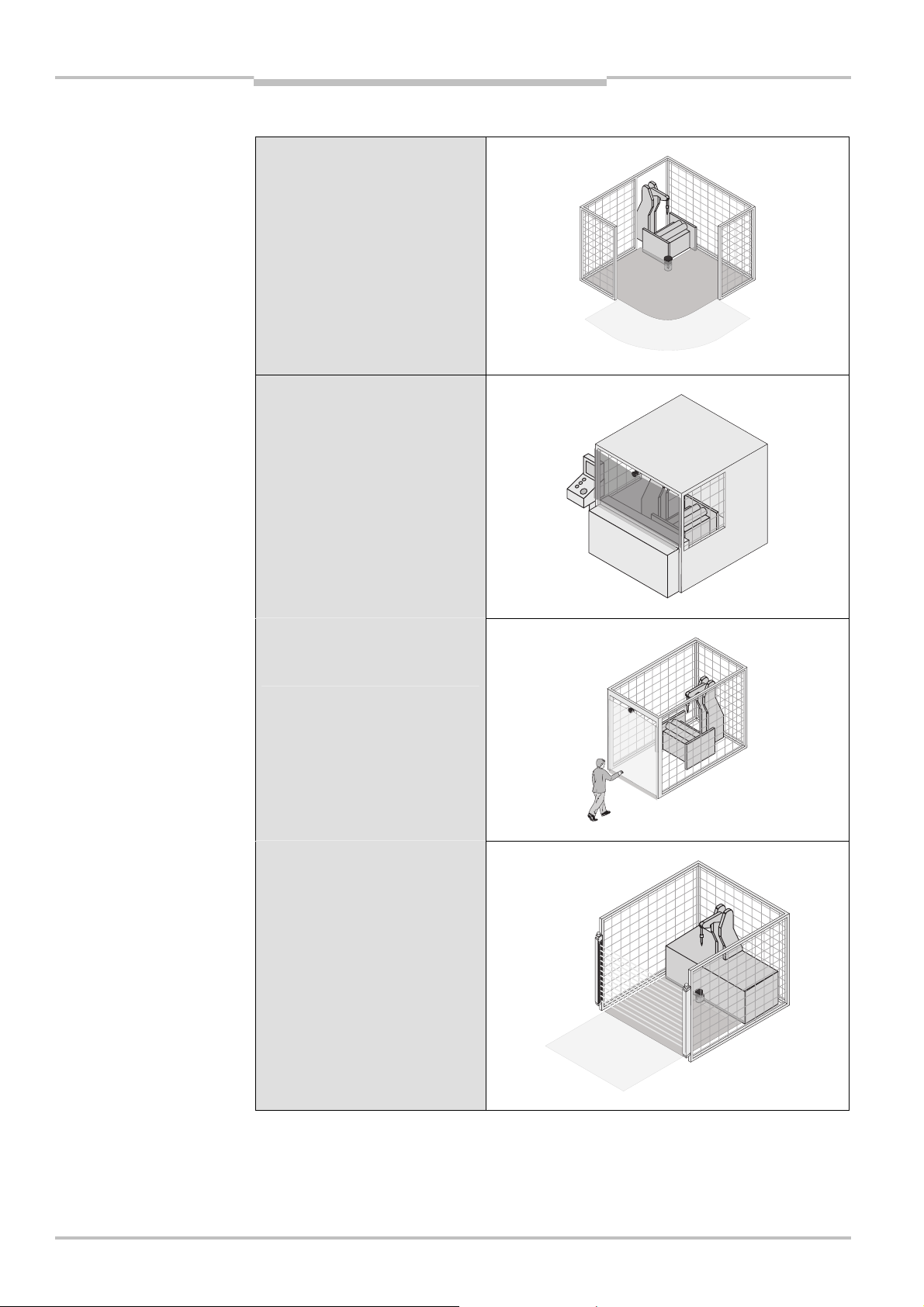
Tab.3:
Possible applications
S300
Product description
3.3.3 Applications
for the S300 variants
S300 Standard:
Hazardous area protection with
one monitored area
S300 Standard:
Hazardous point protection on
an insertion station
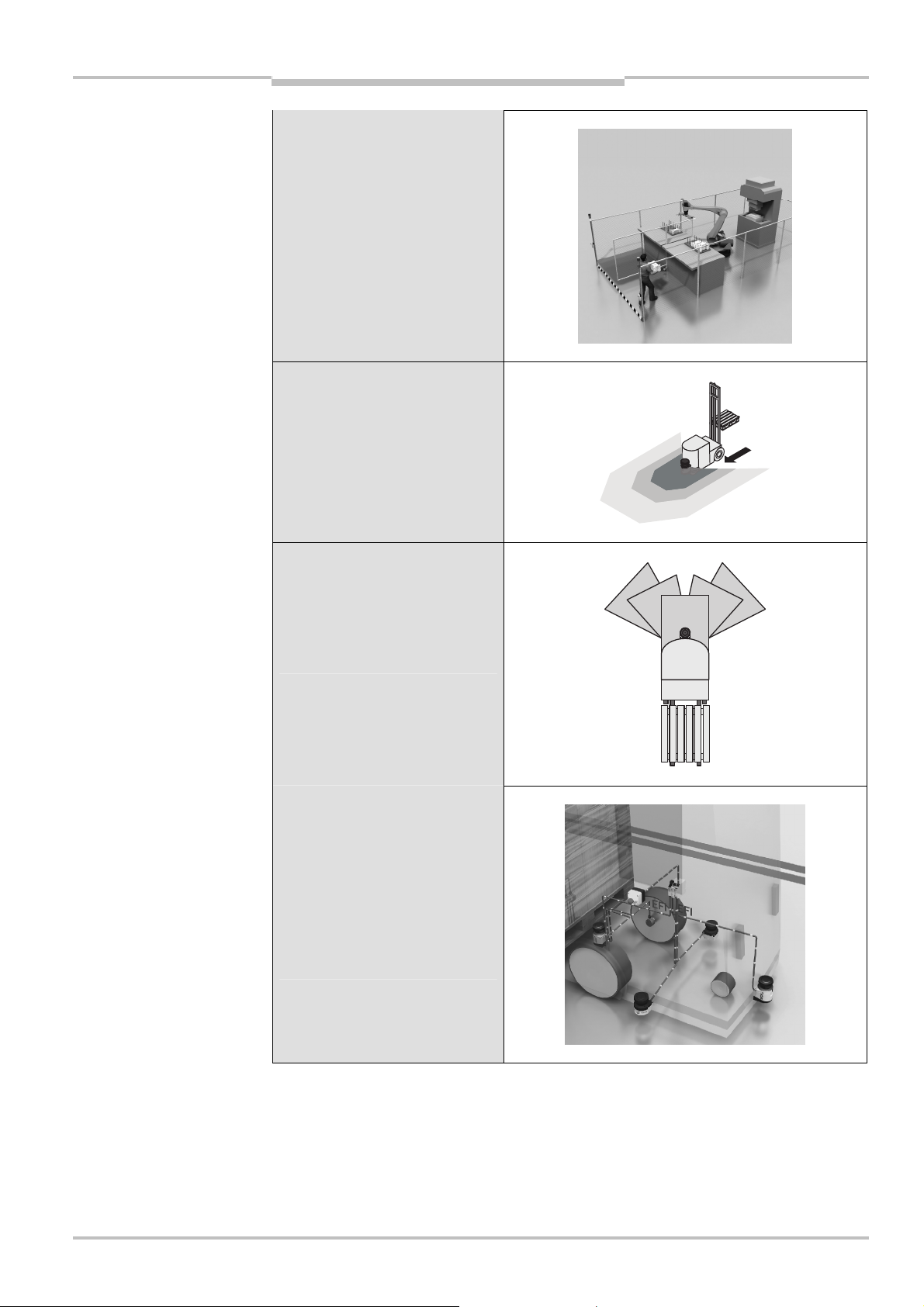
S300 Standard Long Range:
Access protection for high areas
of access
S300 Standard:
Presence detection for a safety
light curtain
22 © SICK AG • Industrial Safety Systems • Germany • All rights reserved 8010948/YY96/2016-02-17
Subject to change without notice
Page 23
Operating instructions Chapter 3
S300
Product description
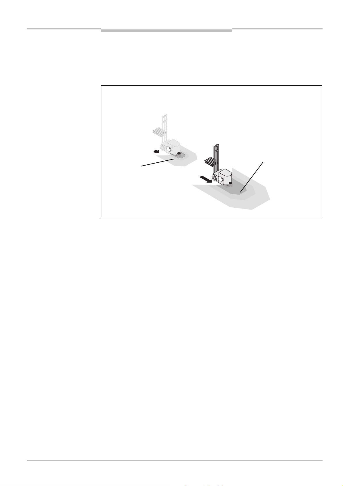
S300 Advanced:
Hazardous area protection with
multiple monitored areas
S300 Advanced:
Freely moving vehicle with two
warning fields
S300 Expert:
Protection of an automated
guided vehicle (AGV) with
protective fields for different
vehicle velocities and driving
around bends
S300 Expert, S300 Professional
in combination with a Flexi Soft
safety controller:
Velocity-dependent protection of
an automated guided vehicle
(AGV). An S300 Expert measures
the velocity and provides the
velocity information to the other
safety laser scanners via EFI.
8010948/YY96/2016-02-17 © SICK AG • Industrial Safety Systems • Germany • All rights reserved 23
Subject to change without notice
Page 24
Chapter 3 Operating instructions
Fig.7:
Status indicators on
S300
Product description
S300 Expert:
Protection of an automated
guided vehicle (AGV) with output
of processed measured data (as
navigation aid, e.g. during
docking maneuvers)
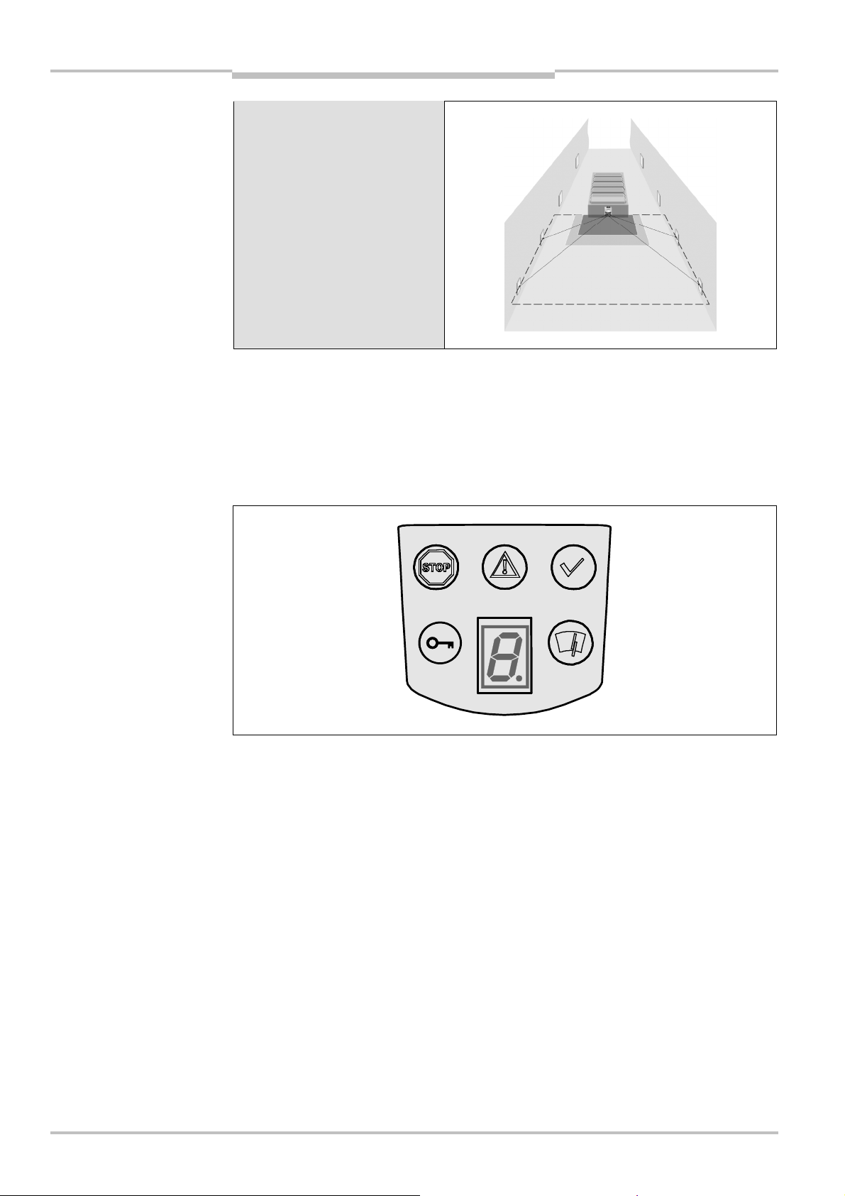
3.4 Status indicators
3.4.1 LEDs and 7@segment display
The LEDs and the 7<segment display indicate the operational status of the S300. They are
on the front face of the safety laser scanner.
the S300
Note
The symbols have the following meaning:
OSSDs in the OFF state (e.g. in case of object in the protective field, monitored contour
changed, reset required, lock-out)
Warning field interrupted (object in warning field)
OSSDs in the ON state (no object in the protective field)
Reset required
Optics cover contaminated
7<segment display for the indication of the status and errors
You will find detailed information in section 11.3 “Error and status indications on the
LEDs” on page 108 and in section 11.4 “Error and status indications on the 7<segment
display” on page 110.
24 © SICK AG • Industrial Safety Systems • Germany • All rights reserved 8010948/YY96/2016-02-17
Subject to change without notice
Page 25
Operating instructions Chapter 3
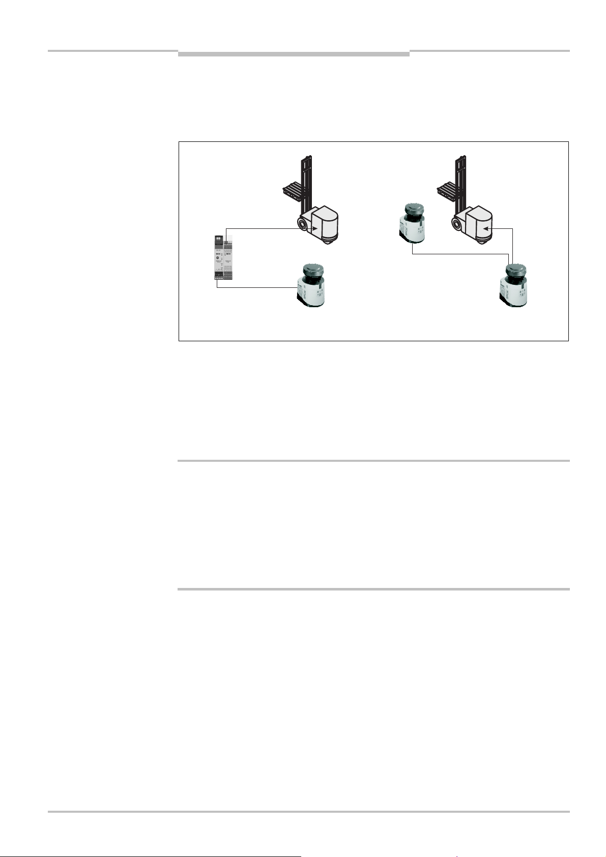
Fig.8:
S300
in combination
EFI system with safety laser scanners
EFI system with Flexi Soft
S300
Product description
3.5 Interoperability
he S300 safety laser scanner can be integrated in an EFI system. An EFI system can
T
comprise two safety laser scanners, a sens:Control device with one to two safety laser
scanners or a safety controller Flexi Soft with up to four safety laser scanners.
with a Flexi Soft safety controller or with another S300
WARNING
Note
Addressing of the guest
If two safety laser scanners are operated on an EFI string, then one is the host, the other
the guest. If only one safety laser scanner is operated on an EFI string, then this device is
the host.
All devices involved can be unambiguously identified by the address and information can
be distributed and retrieved using bit assignment (see also Technical Description “EFI —
Enhanced Function Interface”, SICK part no. 8012621).
In an EFI system with two safety laser scanners, set the address of one of the scanners
to guest!
To be able to unambiguously differentiate between the devices in an EFI system, one S300
must be configured as the guest. For this purpose a jumper is wired between the connection terminals 7 and 13 (see section 6.1.1 “Pin assignment on the system plug” on
page 82).
The jumper always defines the guest device. This jumper is never allowed to be fitted on
the host device.
When the S300 is switched on in an EFI system, the following message appears briefly on
the 7<segment display:
on the S300 host
on the S300 guest
In an EFI system with an S3000 the S300 must be configured as a guest, it is never
allowed to be configured as host.
8010948/YY96/2016-02-17 © SICK AG • Industrial Safety Systems • Germany • All rights reserved 25
Subject to change without notice
Page 26
Chapter 3 Operating instructions
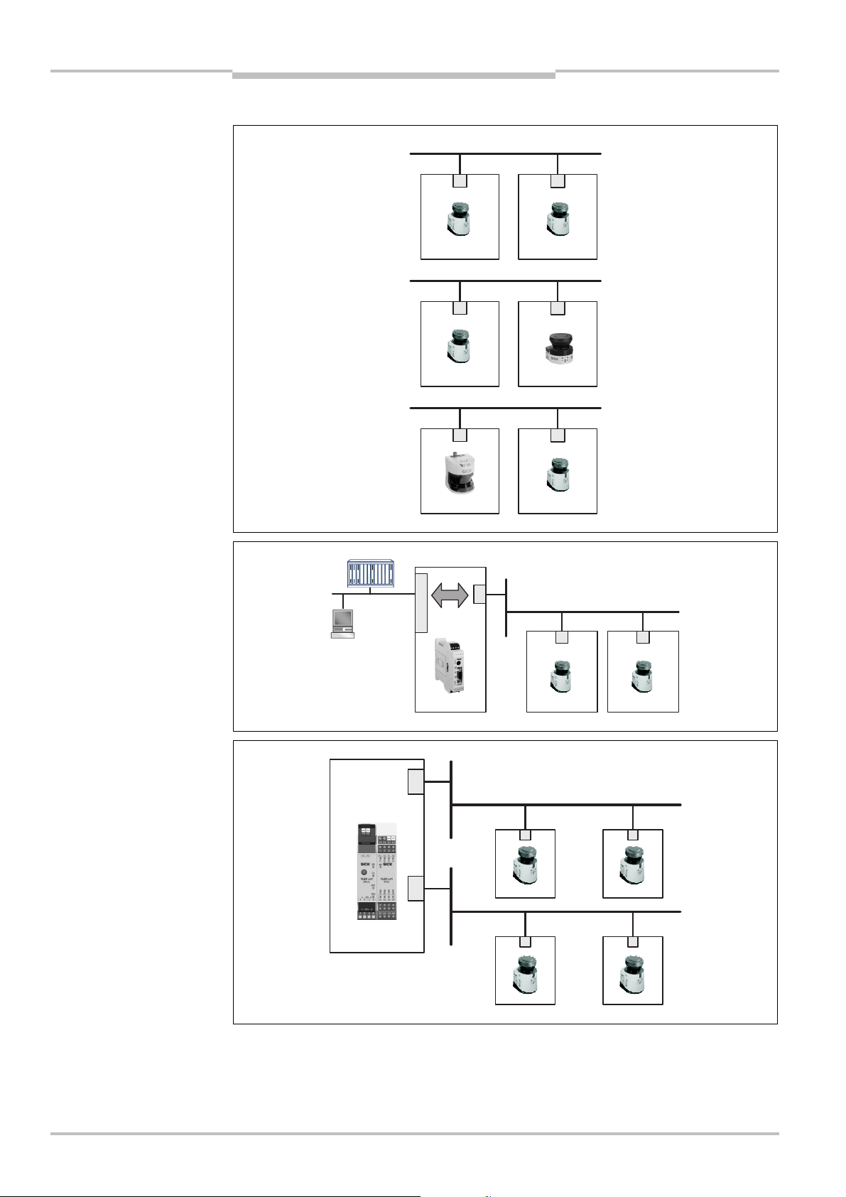
Fig.9:
EFI systems com
-
Fig.10:
EFI system with
Fig.11:
EFI system with
Host
Guest
HostGuest
Host
Guest
Host
Guest
Host
Guest
Host
Guest
Product description
S300
3.5.1 Examples for EFI systems
prising two safety laser
scanners
EFI
EFI
EFI
sens:Control device
Flexi Soft safety controller
e
f
a
OFIs
R
P
FI
E
FI
E
FI
E
26 © SICK AG • Industrial Safety Systems • Germany • All rights reserved 8010948/YY96/2016-02-17
The Flexi Soft safety controller provides two EFI strings; up to two safety laser scanners
(S3000, S300, S300 Mini, also mixed) can be connected to each of these strings. It is
therefore possible to realize applications with up to four safety laser scanners (see also
section 7.2.4 on page 91).
Subject to change without notice
Page 27
Operating instructions Chapter 3
Fig.12:
EFI network
S300
Product description
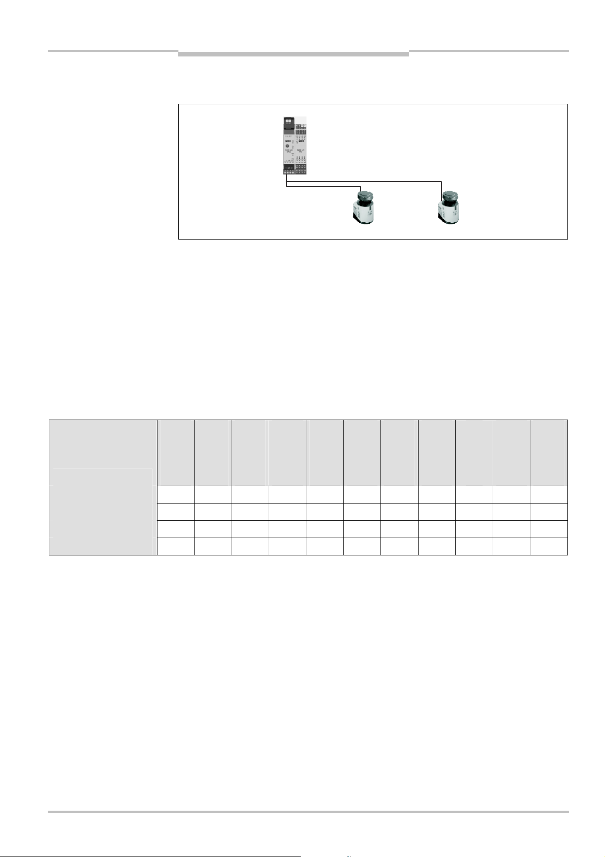
To connect two safety laser scanners to one of the EFI strings on a Flexi Soft safety
controller, wire them radially, as shown in Fig. 12.
topologies
You will find details on the connection of safety laser scanners in section 7.3.8 “Protective
field switching with a Flexi Soft safety controller” on page 96.
3.5.2 Interoperability of the variants
Due to the further development of the safety laser scanner, additional functions, e.g. triple
field technology, have been implemented in the device. As a result the latest devices are
not 100% compatible with safety laser scanners already in use in the field.
To ensure compatibility, the S300 safety laser scanners with firmware M 02.10 and serial
number > 12210000 can be operated in compatibility mode. The following tables show
which devices can form an EFI system.
Interoperability with safety laser scanners
S3000
Standard
S3000
Advanced
S3000
Professional
S3000
Remote
S3000
Expert
S300
Standard
S300
Advanced
S300
Professional
S300 Standard X
S300 Advanced X
S300 Professional X
S300 Expert X
Tab. 4: Interoperability with safety laser scanners
= EFI system possible
X = EFI system not possible
S300 Expert
S300 Mini
Standard
S300 Mini
Remote
8010948/YY96/2016-02-17 © SICK AG • Industrial Safety Systems • Germany • All rights reserved 27
Subject to change without notice
Page 28

Chapter 3 Operating instructions
S300
Product description
Interoperability with safety laser scanners in compatibility mode
(see section 4.1 on page 29)
S3000 Standard
S3000 Advanced
S3000
Professional
S3000
Professional CMS
S3000 Remote
S3000 Expert
S300 Standard
S300 Advanced
S300 Professional
S300 Professional
CMS
S300 Expert
S300 Expert CMS
S300 Mini
Standard
S300 Mini Remote
S300 Standard X X X X X X X X X X X X X X
S300 Advanced X X X
S300 Professional X X X
S300 Expert X X X
Tab. 5: Interoperability with safety laser scanners in compatibility mode
= EFI system possible
X = EFI system not possible
3.5.3 Specific features with EFI systems
Input signals
In an EFI system, the input signals for monitoring case switching are applied to the inputs
on the host or to a safety controller. The guest is connected to the host via EFI and receives from the host the input information for monitoring case switching.
Example
Monitoring case switching
In an EFI system, the host defines the number of possible monitoring cases. If an S300 is
configured as a guest with a higher level device (S3000 or higher grade S300 or
sens:Control device), more monitoring cases may therefore be available depending on the
system configuration.
The S300 Advanced is used on an S300 Professional as a guest. Eight monitoring cases
are configured for the S300 Professional. On the S300 Advanced there are also eight
monitoring cases available in this situation.
Internal or external OSSDs
In an EFI system you define which output signal switching device (OSSD) is switched when
there is an object in the protective field (see section 4.6 on page 39).
Restart interlock/delay
The effectiveness of a restart interlock/delay configured in the S300 is dependent on the
integration of the EFI status information from the S300 in the logic of the Flexi Soft safety
controller (see section 4.7 on page 40).
3.5.4 Interoperability with sens:Control devices
The S300 safety laser scanner can be connected to the following sens:Control devices and
in this way integrated into the related bus systems.
PROFIsafe gateway UE4140-22I0000
PROFIBUS gateway UE1140-22I0000
Ethernet gateway UE1840-22H0000
CANopen gateway UE1940-22I0000
PROFINET IO gateway UE4740-20H0000
28 © SICK AG • Industrial Safety Systems • Germany • All rights reserved 8010948/YY96/2016-02-17
Subject to change without notice
Page 29

Operating instructions Chapter 4
S300
Configurable functions
4 Configurable functions
4.1 Compatibility mode
To ensure compatibility, the S300 safety laser scanners with firmware M 02.10 can be
operated in compatibility mode.
Activate the compatibility mode in the device selection wizard in the CDS.
Reasons why you must activate the compatibility mode or the compatibility mode is
activated automatically by the CDS:
You are using one of the following devices in an EFI system:
– S300 Professional CMS
– S300 Expert CMS
– S300 with firmware < 02.10 and serial number < 12210000
– S300 with system plug serial number < 12210000
– S3000 Professional CMS
– S3000 with firmware < B02.41 and serial number < 12210000
– S3000 Standard, Advanced, Professional with an I/O module with serial
number < 12210000
– S3000 Remote with an I/O module with serial number < 11240000
You configure an S300 with firmware < 02.10 and serial number < 12210000.
You configure an S300 with system plug serial number < 12210000.
You use an S300 with a system plug in which a configuration is saved, …
– that only supports the compatibility mode.
– that has been configured in the compatibility mode.
– that has been configured with a CDS version < 3.6.7.
You want to ensure newly configured devices can be replaced with old devices.
You want to replace old devices with new.
8010948/YY96/2016-02-17 © SICK AG • Industrial Safety Systems • Germany • All rights reserved 29
Subject to change without notice
Page 30

Chapter 4 Operating instructions
Tab.6:
Funct
ions of the
S300
Configurable functions
The table below shows the differences between the functions of the S300 variants in the
compatibility mode.
S300 variants in the
compatibility mode
Notes
Functions
Application diagnostic output “Warning field
interrupted”
Application diagnostic output
“Error/contamination”
Standard
Advanced
Professional
Expert
Application diagnostic output “Reset required”
External device monitoring (EDM)
Restart interlock/delay
Field sets comprising of protective field and one
warning field
Programmable monitoring cases in standalone
mode
1 2 4 8/4
1 2 4 8
4)
Velocity routing using a Flexi Soft safety controller – – – –
The user interface of the CDS in compatibility mode corresponds to the user interface of
CDS version 3.6.6.
The related operating instructions delivered with the device are to be used for older
devices (see 1.3 “Scope” on page 7).
4)
8 field sets at angular resolution 1.0°; 4 field sets at angular resolution 0.5°.
30 © SICK AG • Industrial Safety Systems • Germany • All rights reserved 8010948/YY96/2016-02-17
Subject to change without notice
Page 31

Operating instructions Chapter 4
Configurable functions
S300
Interoperability in an EFI system depending on the firmware version
Firmware
S300 Standard
S300 Standard
S300 Advanced
S300 Advanced
S300 Professional
S300 Professional
S300 Professional
CMS
6)
S300 Expert
S300 Expert
Firmware
M02.10
<02.10
M02.10
<02.10
M02.10
<02.10
<02.10
M02.10
<02.10
S300 Standard M02.10 X – X X X
S300 Advanced M 02.10 X – X X X
S300 Professional M02.10 X – X X X
S300 Expert M02.10 X – X X X
Tab. 7: Required compatibility mode with different firmware versions of the S300 in an EFI system with other S300
= Compatibility mode required
X = Compatibility mode not required5)
– = EFI system not possible
Firmware
S3000 Standard
S3000 Standard
S3000 Advanced
S3000 Advanced
S3000
Professional
S3000
Professional
S3000
Professional CMS
S3000 Expert
S3000 Remote
S300 Expert CMS
6)
<02.10
S3000 Remote
6)
Firmware
MB02.41
ZB02.35
MB02.41
ZB02.35
MB02.41
ZB02.35
ZB02.35
MB02.41
MB02.41
S300 Standard M02.10 X X X X X
S300 Advanced M 02.10 X X X X X
S300 Professional M02.10 X X X X X
S300 Expert M02.10 X X X X X
Tab. 8: Required compatibility mode with different firmware versions of the S300 in an EFI system with other safety laser scanners
= Compatibility mode required
X = Compatibility mode not required
Note
7)
The S300 Mini does not support the compatibility mode. For EFI systems with the S300
Mini safety laser scanner, a device must be used that is not operated in the compatibility
mode.
5)
Make sure that the serial number of the system plug on both devices is > 12210000.
6)
This variant supports exclusively the compatibility mode.
7)
Make sure that the serial number of the S300 system plug is > 12210000 and that the S3000 I/O module is
current (S3000 Standard, Advanced, Professional with I/O module with serial number > 12210000, S3000
Remote with I/O module with serial number > 11240000).
ZB02.35
8010948/YY96/2016-02-17 © SICK AG • Industrial Safety Systems • Germany • All rights reserved 31
Subject to change without notice
Page 32

Chapter 4 Operating instructions
S300
Configurable functions
4.2 System parameters
name can be assigned to the application configured as well as to the safety laser scan-
A
ner(s). The names are saved in the devices after the configuration is transferred. The
name chosen may be, for example, the identifier for the vehicle, system or the machine.
You enter the application name and the names of the safety laser scanners used in the
CDS.
4.2.1 Application name
Enter a name for your application. You can enter a name with a maximum of 16
characters.
If you assign unique application names, you may “reserve” the devices for certain duties. A
machine maintenance person comparing exchanged devices with the configuration data
saved in the CDS will be notified that the application name does not match. He may then
exchange these devices for those with the correct application name.
4.2.2 Name of the scanner
Enter a device name for each of the safety laser scanners in the system. You can enter
names with a maximum of 8 characters.
Recommendation
Use meaningful names, e.g. “front” and “rear” for vehicle monitoring. Unique device
names make the subsequent configuration steps easier (for example on allocating the
control inputs or the OSSDs).
On a host/guest system with two safety laser scanners, the device names must always be
different.
4.2.3 User data
You can enter your name in the field Name of the user. You can enter a name with a maximum of 22 characters. This is then added to the configuration protocol and in the diagnos-
tics report.
4.2.4 Display direction of the 7@segment display
The depiction of numbers on the 7<segment display can be rotated by 180° with the aid of
the CDS. This is useful, for example, when the S300 must be rotated by 180° owing to the
specific assembly.
If you rotate the numbers of the 7<segment display, the point in the 7<segment display
goes out.
How to determine the display direction of the 7@segment display:
Under 7@segment display, activate the Rotated by 180° option. After the configuration
draft has been transferred to the S300, the numbers of the 7<segment display are rota-
ted by 180°.
32 © SICK AG • Industrial Safety Systems • Germany • All rights reserved 8010948/YY96/2016-02-17
Subject to change without notice
Page 33

Operating instructions Chapter 4
Tab.9:
Comparison of mobile
S300
Configurable functions
4.3 Application
With the help of the CDS you can configure the S300 for the required application. Depen-
ding on whether you select a stationary or a mobile application, different configuration
options are available:
and stationary applications
Mobile applications Stationary applications
Resolution
30 mm (hand detection with smaller
protective field size)
40 mm (hand detection with larger
protective field size)
50 mm (leg detection with smaller
protective field size)
70 mm (leg detection with larger
8)
protective field size)
Manipulation prevention
30 mm (hand detection with smaller
protective field size)
40 mm (hand detection with larger
protective field size)
50 mm (leg detection with smaller
protective field size)
70 mm (leg detection with larger
protective field size)
150 mm9)(body detection)
The safety laser scanner checks whether in any 90° segment all measured values
correspond to the maximum distance value that can be measured.
If this is the case, the S300 shuts down
after 2 hours and signals .
If this the case, the S300 shuts down
after 5 seconds and signals .
8010948/YY96/2016-02-17 © SICK AG • Industrial Safety Systems • Germany • All rights reserved 33
Subject to change without notice
8)
In mobile applications a resolution of only 70 mm is required for leg detection, as a coarser resolution is
adequate for the detection of a human leg due to the movement of the vehicle.
9)
Can only be configured with the Long Range variant with 3 m scanning range.
Page 34

Chapter 4 Operating instructions
Tab.10:
Maximum protective
S300
Configurable functions
4.3.1 Resolution
The maximum protective field range
10)
depends on the configured resolution. The following
table shows the related maximum protective field range of the two variants at the resolu-
ions that can be set:
t
field ranges at different
resolutions
Note
Note
Maximum protective field range
Medium Range variant
30 mm (hand detection) 1.25 m
40 mm (hand detection) 1.60 m
50 mm (leg detection) 2.00 m
70 mm (leg detection) 2.00 m
Long Range variant
30 mm (hand detection) 1.25 m
40 mm (hand detection) 1.60 m
50 mm (leg detection) 2.10 m
70 mm (leg detection) 3.00 m
150 mm (body detection) 3.00 m
The warning field can be configured to up to 8 m for all variants and resolutions. The
detection capability within the warning field is dependent on the remission of the objects
to be detected (see Fig. 77 “Diagram scanning range S300 Medium Range” on page 116).
4.3.2 Basic response time
The basic response time of the S300 is 80 ms.
You may need to add supplements to the basic response time due to multiple sampling
and data transmission over EFI (see section 12.2 “OSSD response times” on page 117).
Note
4.3.3 Maximum protective field range
Depending on the configured resolution and the variant used (see section 4.3.1 “Resolution” on page 34), the maximum protective field range of the safety laser scanner is shown
in the CDS.
The maximum protective field range of the S300 must be sufficient to cover the calculated
protective field size including the necessary supplements (see section 5.1.1 “Protective
field size” on page 57).
10)
Radial distance to the safety laser scanner.
34 © SICK AG • Industrial Safety Systems • Germany • All rights reserved 8010948/YY96/2016-02-17
Subject to change without notice
Page 35

Operating instructions Chapter 4
Fig.13:
Calculation of pulses
S300
Configurable functions
4.4 Incremental encoder
he S300 Professional and the S300 Expert have two dual-channel dynamic control inputs
T
using which the possible monitoring cases can be switched as a function of the velocity.
For this purpose incremental encoders must be connected to the dynamic control inputs.
Per incremental encoder, one 0°/90° output is required so that the direction of travel can
be determined.
If you want to use the inputs A and B as dynamic control inputs, select the Indicate
velocity option.
4.4.1 Pulses per cm travel that are output by the incremental encoders
The result is dependent on the number of pulses the incremental encoder supplies per
revolution, and on the ratio between the wheel on the vehicle and the friction wheel on
which the incremental encoder is mounted.
per cm travel
Friction wheel 3.5 cm
Forklift truck wheel
35 cm
Distance covered by the
AGV
How to calculate the number of pulses per centimeter:
Example:
The wheel on a forklift truck has a diameter of 35 cm.
The friction wheel on which the incremental encoder is mounted has a diameter of
3.5 cm.
The incremental encoder used supplies 1000 pulses per revolution.
Circumference of the forklift truck wheel = d × [ = 35 cm × [ = 109.96 cm
One revolution of the forklift truck wheel corresponds to ten revolutions of the friction
wheel and therefore 10,000 pulses from the incremental encoder.
For this information the number of pulses per centimeter of distance covered by the
vehicle is:
Pulses/cm = 10,000 : 109.96 = 90.94
On configuring the incremental encoder in the CDS, you must therefore enter the rounded
value “91” in Pulses per centimeter in the CDS. The user software calculates from this
value the maximum velocity allowed.
8010948/YY96/2016-02-17 © SICK AG • Industrial Safety Systems • Germany • All rights reserved 35
Subject to change without notice
Page 36

Chapter 4 Operating instructions
Fig.14:
Tolerances allowed
S300
Configurable functions
4.4.2 Tolerances allowed on the dynamic inputs
As a rule the same pulse frequency is present at the dynamic inputs when a vehicle moves
in a straight line. On driving around bends or in case of wear e.g. of the vehicle’s tires, the
alues at the two inputs may, however, vary.
v
The velocities from the two incremental encoders may only differ from each other by a
tolerance that can be configured. Deviations are allowed only for a certain time window
(see Fig. 14) depending on the velocity.
The maximum percentage deviation between the two encoder velocities that can be configured is 45%. During this process the higher of the two velocities (irrespective of whether
with positive or negative sign) is used as the reference for this calculation as well as the
vehicle velocity.
Exceeding the tolerance is tolerated for a certain period of time. Then the system switches
to a safe state (lock-out). The period of time is dependent on the vehicle velocity. Fig. 14
shows the deviations that are tolerated and for how long.
on the dynamic inputs
Velocity on input A
Velocity on input B
If the vehicle velocity is in the range between –10 cm/s and +10 cm/s, then there is no
shut down, irrespective of how long the deviation between the incremental encoders is
present.
If the vehicle velocity is between –30 and –10 cm/s or +10 and +30 cm/s, then the
maximum period of time for which a deviation is tolerated is 60 s.
If the vehicle velocity is in the range Z–30 cm/s or M+30 cm/s, then the maximum
period of time for which a deviation is tolerated is 20 s.
If the vehicle velocity is in the range Z–10 cm/s or M+10 cm/s, then different directions
of rotation on the incremental encoders are only tolerated for 0.4 s.
36 © SICK AG • Industrial Safety Systems • Germany • All rights reserved 8010948/YY96/2016-02-17
Subject to change without notice
Page 37

Operating instructions Chapter 4
Fig.15:
Possible ways of
S300
Configurable functions
4.5 Inputs
t is possible to switch between the monitoring cases of the S300 during operation. There
I
are various ways of achieving this switching:
monitoring case switching
Local static inputs (S300 Advanced, Professional and Expert)
External static inputs via EFI (all S300 variants)
Local dynamic inputs (S300 Professional and Expert)
Velocity information via EFI
– indicate and use velocity (S300 Professional and Expert)
– use velocity (all S300 variants)
During the configuration of an EFI system you define in the CDS the device in which the
inputs are used.
Standalone operation
In standalone operation of an S300 use the local inputs of the S300.
The S300 Advanced has two dual-channel static control inputs A and B.
The S300 Professional and the S300 Expert have three dual-channel control inputs. Of
these control inputs, the inputs A and B can be used as both static control inputs and also
dynamic control inputs.
The dual-channel control input C is formed by the Universal I/O1 and Universal I/O5
connections.
Activate the inputs you want to use for monitoring case switching.
If you activate the Use velocity option, you can use velocity ranges for monitoring case
switching.
8010948/YY96/2016-02-17 © SICK AG • Industrial Safety Systems • Germany • All rights reserved 37
Subject to change without notice
EFI system
If devices are connected together via EFI, the S300 can receive control commands from
other devices, e.g. a second S300 or Flexi Soft safety controller. Tab. 37 on page 131
shows the possible control commands of the S300.
In an EFI system you configure which device you want to use for obtaining the input
information.
If the S300 is connected to a Flexi Soft safety controller, up to five dual-channel control
inputs can be configured.
Page 38

Chapter 4 Operating instructions
Tab.11:
Figure from experi
-
Tab.12:
Level at the connec
-
Tab.13:
Truth table for
S300
Configurable functions
4.5.1 Input delay
If the control device via which you switch the static control inputs cannot switch within
10 ms to the related input condition (e.g. due to switch bounce times), you must configure
n input delay. For the input delay choose the time in which your defined control device
a
can switch to a corresponding input condition.
The following figures, based on experience, give input delays for various methods of
switching:
ence for the necessary input
delay
Note
Switching method Input delay required
Electronic switching using controller or
10 ms
complementary electronic outputs with
0 to 10 ms bounce time
Contact (relay) controls 30-150 ms
Control using independent sensors 130-480 ms
Also pay attention to the notes in section 5.6 “Time for monitoring case switching” on
page 71.
4.5.2 Sampling for the static control inputs
If you are using static sampling, decide between complementary or 1<of<n sampling depen-
ding on the control features available. Depending on this selection you can define the
switching criteria for the monitoring cases (see section 4.10.1 “Monitoring case switching
via static input information” on page 48).
Complementary sampling
One control input comprises two connections. For correct switching one connection must
be inverted in relation to the other.
The following table shows the levels that must be present at the connections for the control input to define the logical input state 1 and 0 at the related control input.
tions for the control inputs for
complementary sampling
16of6n sampling with two
input pairs
Notes
A1 A2 Logical input state
1 0 0
0 1 1
1 1 Error
0 0 Error
1-of-n sampling
With 1-of-n sampling you use the single connections of the control input pairs.
A1 A2 B1 B2 Result (e.g. monitoring case no.)
1 0 0 0 1
0 1 0 0 2
0 0 1 0 3
0 0 0 1 4
0 0 0 0 Error
1 1 0 0 Error
All connections must be connected.
Only one connection is ever allowed to be 1.
38 © SICK AG • Industrial Safety Systems • Germany • All rights reserved 8010948/YY96/2016-02-17
Subject to change without notice
Page 39

Operating instructions Chapter 4
fer
Tab.14:
Behavior of the
S300
Configurable functions
4.6 OSSDs
n an EFI system you define in the CDS which output signal switching device (OSSD) is
I
switched when there is an object in the protective field.
Internal OSSDs
Defines that the protective field or the protective fields switch the OSSDs on S300.
External OSSDs
The S300 transmits the status of the field sets (protective field/warning fields) via EFI.
The OSSDs on another device connected via EFI have switched.
– Connected S300 or S3000: The OSSDs on the second safety laser scanner are
switched.
– Connected safety controller (e.g. Flexi Soft): The OSSDs on the safety controller are
switched depending on its configuration.
– Connected network solution (e.g. safety remote I/O): The information is passed via the
network e.g. to an FPLC that must shutdown the dangerous state.
Do not use the OSSD bit for safety relevant functions!
If the local OSSDs on the S300 are not used, the OSSD state is always transferred as
WARNING
active via EFI. In this case the OSSD bit in the Flexi Soft safety controller is not allowed to
be used for safety-related functions.
WARNING
The status of the protective fields is transmitted using EFI and can be combined in the
safety controller Flexi Soft as required. The signal of the safety outputs on the Flexi Soft
safety controller is transferred, e.g., to a machine or vehicle control.
Pay attention to the logical values for the protective field status information on trans
to the Flexi Soft safety controller!
The status of an evaluated protective field is logical 1 if the protective field is unoccupied,
the status is logical 0 if the protective field is infringed (see section 12.5 “EFI status
information and control commands” on page 129). The status of a protective field that is
not evaluated is always logical 1.
4.6.1 External device monitoring (EDM)
The EDM checks if the contactors actually de-energize when the protective device is
tripped. If you activate external device monitoring, then the S300 checks the contactors
after each interruption of the protective field and prior to the machine restart. The EDM
can so identify if one of the contactors has welded, for instance. In this case the external
device monitoring places the system in a safe operational state and the OSSDs are not
switched back to the ON state.
The table shows how the S300 reacts if the external device monitoring detects a contactor
malfunction:
S300 on a contactor
malfunction
8010948/YY96/2016-02-17 © SICK AG • Industrial Safety Systems • Germany • All rights reserved 39
Subject to change without notice
Without internal restart
interlock
or
with restart delay
With restart interlock The S300 switches its OSSDs to the OFF state.
The system locks completely (lock-out).
The error message appears in the 7<segment display.
The LED is illuminated.
The error message appears in the 7<segment display.
Page 40

Chapter 4 Operating instructions
S300
Configurable functions
You can configure the external device monitoring in the CDS.
Notes
WARNING
You will find examples on the connection of the external device monitoring in section 7.3
“Connection diagrams” on page 92.
If you do not use the external device monitoring function, leave the inputs disconnected
(see section 6.1.1 “Pin assignment on the system plug” on page 82).
4.7 Restart
You can configure the restart behavior of the S300 as follows:
without restart interlock
with restart delay
with restart interlock
You can configure the type of restart in the CDS.
It is imperative that you configure the S300 with restart interlock if the protective field
can be left to approach the hazardous point or if a person cannot be detected at every
point in the hazardous area for the S300!
During the assessment, pay attention to whether the protective field can be left in the
direction of the hazardous point, to areas that are unprotected due to the mounting and
the unprotected near range of the S300 (see section 5.5 “Methods of preventing unpro-
tected areas” on page 69).
Restart behavior on the integration of the S300 into a Flexi Soft safety controller
The effectiveness of a restart interlock/delay configured in the S300 is dependent on the
integration of the EFI status information from the S300 in the logic of the Flexi Soft safety
controller.
The internal restart interlock/delay acts on the OSSD of the S300. If the status informa-
tion on the OSSDs is used in the Flexi Soft safety controller, then the restart interlock/
delay also acts on the Flexi Soft safety controller.
If the status information on the protective fields is used in the Flexi Soft safety controller,
the restart interlock/delay does not affect the Flexi Soft safety controller (see section 12.5 “EFI status information and control commands” on page 129). In this case you
must realize a restart interlock/delay in the Flexi Soft safety controller.
Configuration of the S300 without restart interlock
After the OSSDs on the S300 have been switched to the OFF state due to an object in the
protective field, the OSSDs are re-enabled again immediately when there is no longer an
object in the active protective field.
This configuration is only allowed …
if an external restart interlock is realized on the machine controller
or
if the protective field cannot be left in the direction of the hazardous point and if people
can be detected by the S300 at every point in the hazardous area!
Restart delay for mobile applications
In mobile applications you can configure a restart delay from 2 to 60 seconds on the
S300. The OSSDs on the S300 switch to the ON state if there is no object in the protective
field for the duration given.
40 © SICK AG • Industrial Safety Systems • Germany • All rights reserved 8010948/YY96/2016-02-17
Subject to change without notice
Page 41

Operating instructions Chapter 4
Fig.16:
Schematic outline of
S300
Configurable functions
This configuration is only allowed if the protective field cannot be left in the direction of the
hazardous point and if a person can be detected at every point in the hazardous area by
the S300!
Configuration of the S300 with restart interlock
the operation with restart
interlock
Note
WARNING
Notes
Note
Do not confuse the restart interlock with the starting interlock on the machine. The starting
interlock prevents the machine starting after switching on. The restart interlock prevents
the machine starting again after an error or a protective field infringement.
The OSSDs on the S300 switch to the OFF state to initiate a machine or vehicle stop as
soon as there is an object in the protective field . They do not switch to the ON state ,
even if there is no longer an object in the protective field. The OSSDs only switch to the ON
state if the operator operates the control switch for restart or reset.
Place the control switch for restart or reset outside the hazardous area in a place
where it can clearly be seen from the hazardous area!
Place the control switch for restart or reset outside the hazardous area such that it cannot
be operated by a person in the hazardous area. Ensure that the person who operates the
control switch has a full view of the hazardous area.
You will find examples on the connection of the internal restart interlock in section 7.3
“Connection diagrams” on page 92.
If you do not use the internal restart interlock, leave the inputs disconnected (see
section 6.1.1 “Pin assignment on the system plug” on page 82).
Reset
The reset function is often also called “preparation for restart”. In these operating instructions the term reset is used.
If you want to activate the restart interlock on the S300 (internal) and also a restart inter-
lock on the machine (external), then each restart interlock has its own control switch.
After operating the control switch for the internal restart interlock (with protective field
unoccupied) …
the S300 switches its OSSDs to the ON state.
the LED on the safety laser scanner illuminates green.
The external restart interlock prevents the machine from restarting. After resetting the
S300 the operator must press the control switch to restart the machine controller.
8010948/YY96/2016-02-17 © SICK AG • Industrial Safety Systems • Germany • All rights reserved 41
Subject to change without notice
WARNING
Ensure that the correct sequence is followed!
The controller must be realized such that the machine only restarts if the S300 is first
reset and then the control switch for restarting the machine controller is operated.
Page 42

Chapter 4 Operating instructions
Tab.15:
Configuration
Fig.17:
Configuration
S300
Configurable functions
4.8 Universal I/O connections
ou are not allowed to use the universal I/O connections for safety-relevant functions!
Y
You are only allowed to use the universal I/O connections for signaling. You must never
ARNING
W
use the signals for controlling the application or for safety-relevant functions.
The S300 has five universal I/O connections. You can configure these five connections for
one or more of the following functions (OR operator):
As inputs:
11)
I/O1
as reset
I/O2 as EDM or Reset
As outputs:
1)
1
I/O3, I/O4 and I/O5
options of the universal I/O
connections as outputs
example universal I/O
connections of the S300
In standalone operation In an EFI system with another safety laser scanner
Error
Contamination error
Contamination warning
Warning field 1
Warning field 2
Reset required
Protective field (host/guest)
Warning field 1 (host/guest)
Warning field 2 (host/guest)
Simultaneous protective field of the host, if the host
is an S3000 in dual field mode
Simultaneous warning field of the host, if the host is
an S3000 in dual field mode
The universal I/O connections are configured in the CDS in the Universal I/O area. Fig. 17
shows a configuration example.
42 © SICK AG • Industrial Safety Systems • Germany • All rights reserved 8010948/YY96/2016-02-17
Note
If you operate the S300 in the compatibility mode, then the connections on the univer-
sal I/O are used as application diagnostic output, warning field output and application
diagnostic output for reset required.
11)
Not available if input C is used.
Subject to change without notice
Page 43

Operating instructions Chapter 4
Tab.16:
Number of field sets
Fig.18:
Creating a field set
S300
Configurable functions
4.8.1 Application diagnostic output in the compatibility mode
The S300 variants have a configurable application diagnostic output in the compatibility
mode. For the application diagnostic output you configure in the CDS …
whether it is deactivated.
whether a signal is only output when the optics cover is contaminated.
whether a signal is only output on errors.
whether a signal is output both for optics cover contamination and on errors.
4.9 Field sets
The number of field sets that can be configured is dependent on the safety laser scanner
variant. The following table shows the number of field sets per variant:
that can be configured per
variant
in the CDS
Standard Advanced Professional Expert
Number of field sets 1 4 8 16
4.9.1 Configuring the protective field and warning field
With the aid of the CDS you can configure the field set, which comprises a protective field
and two warning fields . During this process you configure the shape and size of the
protective and warning fields. You can realize any field shape required.
8010948/YY96/2016-02-17 © SICK AG • Industrial Safety Systems • Germany • All rights reserved 43
Subject to change without notice
Note
WARNING
The area to be monitored is scanned radially by the S300. The S300 cannot see through
objects during this process. The area behind objects that are in the area to be monitored
(pillars, grilles, etc.) can thus not be monitored.
Protective fields and warning field can cover up an angle of up to 270° and have different
radial scanning ranges depending on the variant and the resolution configured (see section 4.3.1 “Resolution” on page 34).
Check the protective fields configured!
Prior to commissioning the machine or vehicle, check the configuration of the protective
fields. Please observe the notes in chapter 9 “Commissioning” on page 99 and in the
checklist on page 140
Page 44

Chapter 4 Operating instructions
Fig.19:
Configuring protec
-
S300
Configurable functions
Note
tive field and warning field
WARNING
If the protective field or the warning fields stretch as far as a wall or another object
(pillar, neighboring machine, shelf), there should be a distance of 100 mm between the
protective field or warning field and the object to prevent false triggering .
Secure unprotected areas!
If it is possible to access a narrow strip between the protective field and a wall or another
object, you must protect this strip using additional measures (e.g. fence or floor protec-
tion).
44 © SICK AG • Industrial Safety Systems • Germany • All rights reserved 8010948/YY96/2016-02-17
Subject to change without notice
Page 45

Operating instructions Chapter 4
Fig.20:
Reading the
S300
protective field
Configurable functions
4.9.2 Protective field or warning field suggested by the safety laser scanner
The CDS can suggest the protective field or warning field in the field set editor. The safety
laser scanner scans the visible surrounding contour several times. From the data obtained
he CDS suggests the contour and size of the field. The following figure shows an example
t
for the reading of a protective field:
Note
WARNING
In those places at which the surrounding contour is smaller than the maximum protective
field range (e.g. at ), the protective field corresponds to the surrounding contour.
The measuring error tolerances for the S300 are automatically subtracted from the protective field size. As a result the protective field is slightly smaller than the surface covered .
In those places where the surrounding contour is larger than the protective field range ,
the protective field corresponds to the possible scanning range.
Check the protective field suggested!
The protective field suggested by the CDS is not a replacement for the calculation of the
minimum distance. Calculate the minimum distance and check the effectiveness of the
protective fields prior to commissioning the application!
Pay attention to the descriptions in chapter 5 “Mounting” on page 56, the notes in chap-
ter 9 “Commissioning” on page 99 and the checklist on page 140.
8010948/YY96/2016-02-17 © SICK AG • Industrial Safety Systems • Germany • All rights reserved 45
Subject to change without notice
Page 46

Chapter 4 Operating instructions
Fig.21:
Schematic diagram
S300
of contour as reference
Notes
Configurable functions
4.9.3 Using the contour as a reference
In addition to the protective field, the S300 can also monitor a contour (e.g. the floor in
vertical applications or the wall in horizontal applications).
For contour monitoring you define a contour segment . The contour segment comprises a
positive and a negative tolerance band.
The OSSDs on the S300 switch to the OFF state if …
there is an object in the protective field.
the monitored surrounding contour is no longer in the tolerance band (e.g. if a door is
opened or if the position of the S300 is changed).
You can define any number of contour segments.
The contour segments must not be narrower than the configured resolution.
At the points where a contour has been configured as a reference you cannot define
warning fields. If, for example, you use the floor as a reference for access protection, you
cannot configure a warning field there. However, you can, e.g., configure a warning field
to the left and right of the contour segment to control a warning signal on approach from
the side.
The contour as reference function and the warning field 2 function are mutually exclu-
sive.
You define the contour as a reference in the CDS field set editor.
46 © SICK AG • Industrial Safety Systems • Germany • All rights reserved 8010948/YY96/2016-02-17
Subject to change without notice
Page 47

Operating instructions Chapter 4
Fig.22:Contour as reference
Tab.17:
Number of monito
-
S300
Configurable functions
Vertical operation
In vertical operation (for access protection and hazardous point protection) according to
EC 61496<3 you must always configure the protective fields used with the contour as
I
reference function.
for vertical operation
Protective field
Contours of the machine
opening
Contour segment
Recommendation
WARNING
ring cases per variant and
application
Use lateral, vertical boundaries of the opening (e.g. door frame) and the floor as reference.
If in this case the position of the S300 is changed in one or more planes, the distance to
the reference changes and the S300 switches its OSSDs to the OFF state.
4.10 Monitoring cases
The S300 supports a configuration with multiple monitoring cases. By switching the moni-
toring case you can switch to different monitoring conditions in the case of a change to the
monitoring situation.
Ensure for each monitoring case that the minimum distance to the hazardous area is
maintained!
See chapter 5 “Mounting” on page 56.
The number of monitoring cases that can be configured is dependent on the variant and
on the control. The following table shows the number of monitoring cases:
Standard Advanced Professional Expert
Applications with local static control inputs on the S300
1 4 8 8
Applications with static control inputs via EFI (e.g. on a Flexi Soft)
8010948/YY96/2016-02-17 © SICK AG • Industrial Safety Systems • Germany • All rights reserved 47
Subject to change without notice
32 32 32 32
Applications with dynamic control inputs on the S300 or via EFI
– – 32 32
Applications with dynamic control inputs via EFI
32 32 32 32
Page 48

Chapter 4 Operating instructions
S300
WARNING
Configurable functions
You can configure the monitoring cases in the CDS.
Each monitoring case includes …
the input conditions, the so-called control signals, that control the activation of the
monitoring case.
a field set, comprising of protective field and warning field or fields.
if necessary, a unique follow-on case or two alternative follow-on cases.
the multiple sampling for the field set.
Monitoring cases can be switched with the following input information:
static information
velocity information
a combination of both
4.10.1 Monitoring case switching via static input information
For monitoring case switching via static input information, configure for each monitoring
case the input condition to be used to switch to the monitoring case.
When switching the monitoring cases using static control inputs, please note the
following points:
Ensure that the control for the monitoring case switching has the required level of safety.
Ensure that the circuit for the control inputs is suitable for the ambient conditions to be
expected so that systematic and design-related effects and resulting errors on the
switching of the monitoring cases can be excluded.
Ensure that the control — using static control inputs — provides switching between the
monitoring cases in the correct time frame. Note that at the time of the switching there
may be a person in the protective field. Only by means of switching in the correct time
frame (i.e. before the hazard occurs at this point for the person) is protection provided
(see section 5.6 “Time for monitoring case switching” on page 71).
48 © SICK AG • Industrial Safety Systems • Germany • All rights reserved 8010948/YY96/2016-02-17
Subject to change without notice
Page 49

Operating instructions Chapter 4
Tab.18:
Truth table with
S300
Configurable functions
Static complementary sampling
Using the two control input pairs on the S300 Advanced 2
witched, using the three control input pairs on the S300 Professional and Expert 2
s
2
= 4 monitoring cases can be
3
8
=
monitoring cases can be switched.
Using external inputs (e.g. those of a Flexi Soft safety controller, see section 4.5 “Inputs”
on page 37), 2
5
= 32 monitoring cases can be switched via maximally five control input
pairs.
complementary evaluation
Note
A B C D E E.g. case
0 0 0 0 0 1
1 0 0 0 0 2
0 1 0 0 0 3
1 1 0 0 0 4
0 0 1 0 0 5
1 0 1 1 0 6
0 1 1 0 0 7
1 1 1 0 0 8
… …
0 1 1 1 0 15
1 1 1 1 0 16
0 0 0 0 1 17
… …
0 1 1 1 1 31
1 1 1 1 1 32
Undefined input information will result in the S300 switching the OSSDs to the OFF state
or signaling Protective field infringed via EFI.
8010948/YY96/2016-02-17 © SICK AG • Industrial Safety Systems • Germany • All rights reserved 49
Subject to change without notice
Page 50

Chapter 4 Operating instructions
Tab.19:
Truth table for
S300
Configurable functions
Static 1-of-n sampling
With 1-of-n sampling you use the single connections of the control input pairs. In this way
he S300 Advanced provides four and the S300 Professional/Expert six input connections.
t
Notes
Using external inputs, maximally ten input connections can be used (e.g. those of a Flexi
Soft safety controller, see section 4.5 “Inputs” on page 37).
All connections must be connected!
One connection must be 1!
Only one connection is ever allowed to be 1!
16of6n sampling
A1 A2 B1 B2 C1 C2 D1 D2 E1 E2 E.g. case
1 0 0 0 0 0 0 0 0 0 1
0 1 0 0 0 0 0 0 0 0 2
0 0 1 0 0 0 0 0 0 0 3
0 0 0 1 0 0 0 0 0 0 4
0 0 0 0 1 0 0 0 0 0 5
0 0 0 0 0 1 0 0 0 0 6
0 0 0 0 0 0 1 0 0 0 7
0 0 0 0 0 0 0 1 0 0 8
0 0 0 0 0 0 0 0 1 0 9
0 0 0 0 0 0 0 0 0 1 10
1 1 0 0 0 0 0 0 0 0 Error
0 0 0 1 1 0 0 0 0 0 Error
0 0 0 0 0 0 0 0 0 0 Error
and all other combinations Error
50 © SICK AG • Industrial Safety Systems • Germany • All rights reserved 8010948/YY96/2016-02-17
Subject to change without notice
Page 51

Operating instructions Chapter 4
S300
Configurable functions
4.10.2 Monitoring case switching via velocity information
When switching the monitoring cases using dynamic control inputs, please note the
following points:
WARNING
Ensure that the control — using dynamic control inputs (incremental encoder inputs) —
provides switching between the monitoring cases in the correct time frame. Note that at
the time of the switching there may be a person in the protective field. Only by means of
switching in the correct time frame (i.e. before the hazard occurs at this point for the
person) is protection provided (see section 5.6 “Time for monitoring case switching” on
page 71).
Ensure that only one safety laser scanner is connected to an incremental encoder.
Two incremental encoders are necessary to detect a possible fault in one encoder.
It is imperative you lay the connecting cables to the incremental encoders separately.
Prerequisites
For dynamic sampling using incremental encoders, configure …
the Use velocity option (see section 4.4 “Incremental encoder” on page 35).
for each monitoring case the velocity range for switching to the monitoring case.
Note
Example:
Monitoring case 1 (standstill) –10 … +10 cm/s
Monitoring case 2 (forward movement 1) 11 … 50 cm/s
Monitoring case 3 (forward movement 2) 51 … 100 cm/s
Monitoring case 4 (forward movement 3) 101 … 200 cm/s
During the configuration of the monitoring cases in the CDS, you must cover all possible or
allowed velocities of the vehicle. An undefined velocity will result in the switching of the
OSSDs to the OFF state (useful e.g. for safe maximum velocity monitoring on vehicles).
8010948/YY96/2016-02-17 © SICK AG • Industrial Safety Systems • Germany • All rights reserved 51
Subject to change without notice
Page 52

Chapter 4 Operating instructions
Fig.23:
Example for velocity
Fig.24:
Connection diagram
S300
Configurable functions
4.10.3 Velocity routing via EFI
If several safety laser scanners are connected to a Flexi Soft safety controller, then a velocity routing can be configured. In this way the velocity information that is determined by an
300 Professional or Expert with the aid of incremental encoders is distributed to all safe-
S
ty laser scanners.
The velocity routing is not available in the compatibility mode.
ote
N
routing on an AGV
S300 Expert on EFI1.1
Incremental encoder
S300 Mini on EFI2.2
Flexi Soft
S300 Mini on EFI1.2
S300 on EFI2.1
for velocity routing
S300 Expert on EFI1.1
Incremental encoder
S300 Mini on EFI2.2
Flexi Soft
S300 Mini on EFI1.2
S300 on EFI2.
Incremental encoders are connected to the S300 Expert on EFI1.1 . These generate
the necessary velocity signals. The signals are distributed by the Flexi Soft safety controller
to all four safety laser scanners ( and as well as and ) and are available on all
four safety laser scanners for monitoring case switching.
52 © SICK AG • Industrial Safety Systems • Germany • All rights reserved 8010948/YY96/2016-02-17
Subject to change without notice
Page 53

Operating instructions Chapter 4
With a multiple sampling greater than 2, note that you must add a supplement to the basic
Fig.25:
Example for velocity
S300
Configurable functions
How to configure a velocity routing in the Flexi Soft Designer:
Configure the velocity routing in the Flexi Soft Designer for instance as in the following
igure.
f
routing in the Flexi Soft
Designer
Input signals from the
S300 Expert with
incremental encoders
12 + 1 bit pattern
duplicated and placed
on the n:n function
blocks EFI1.1
Output signals to all
safety laser scanners
EFI string 1 (safety
laser scanner on
EFI1.1 and
EFI1.2 )
EFI string 2 (safety
laser scanner on
EFI2.1 and
EFI2.2 )
The velocity signals of the S300 Expert are broken down into a 12 + 1 bit pattern, 12 velo-
city bits and one bit for validation. These signals are available as input signals, are duplicated and placed twice on the n:n function blocks (0 and 1 as well as 2 and 3).
The outputs of the function blocks are placed on EFI string 1 or on EFI string 2. As a result
they are available to all four safety laser scanners.
WARNING
The “Speed valid” status information is relevant for safety!
Ensure that the Speed valid input signal is connected to the Speed valid output signal.
How to configure the safety laser scanners in the CDS:
On the Incremental encoder tab for the S300 Expert to which the incremental encoders
are connected, select the Indicate velocity option.
All safety laser scanners, also the sending devices, must use these velocity signals via EFI.
For this reason activate on all safety laser scanners on the Inputs tab the option Use
Flexi Soft CPU1.
Then, select on all safety laser scanners on the Inputs tab the Use velocity option.
4.10.4 Multiple sampling
If multiple sampling is set, an object must be scanned several times before the S300
switches its OSSDs to the OFF state. In this way you can reduce the probability that insects, welding sparks or other particles result in the shutdown of the system.
If a multiple sampling of 3 is configured, for instance, an object must be detected in the
protective field three times in succession before the S300 switches the OSSDs to the OFF
state.
The total response time is increased by the multiple sampling!
WARNING
8010948/YY96/2016-02-17 © SICK AG • Industrial Safety Systems • Germany • All rights reserved 53
Subject to change without notice
response time (see section 12.2 “OSSD response times” on page 117)!
Page 54

Chapter 4 Operating instructions
Tab.20:
Recommended
Fig.26:
Schematic layout
S300
Configurable functions
On the S300, a multiple sampling of 2 is the minimum setting. You can set the multiple
sampling to up to 16 with the aid of the CDS. The supplement to the basic response time
resulting from your setting is displayed in the CDS.
multiple sampling
Recommendation
Recommendation
Application Recommended multiple sampling
Stationary under clean ambient conditions 2 times
Vertical applications 2 times
Mobile 4 times
Stationary under dusty ambient conditions 8 times
Using multiple sampling you can increase the availability of a system.
You can configure the multiple sampling in the CDS. You can set individual multiple samp-
ling for each monitoring case.
4.10.5 Checking of the monitoring case switching
To check the switching between monitoring cases, configure a series of monitoring cases.
Here you can define either an arbitrary sequence, a unique sequence, or two alternative
sequences.
Arbitrary sequence: It is allowed to switch from one monitoring case to any other defined
monitoring case.
Unique sequence: It is only allowed to switch from a monitoring case to another specifi-
cally defined monitoring case.
Alternative sequence: It is allowed to switch from a monitoring case to one of two specifi-
cally defined monitoring cases.
Use the monitoring of the monitoring case switching as an additional check on your con-
trol. For example, in this way deviations of a vehicle from a corridor or a system from the
stipulated production process can be detected.
of the monitoring case
switching
Arbitrary sequence Unique sequence Alternative sequence
You can configure the sequence of monitoring cases in the CDS.
4.10.6 Park/stand-by mode
If, in mobile applications, vehicles are not moved for a time (e.g. for battery charging), the
OSSDs can be switched to the OFF state and the laser on the S300 can be switched off. In
this way the power consumption of the device is reduced.
In this way you also prevent the safety laser scanners from dazzling each other and enter-
ing an error condition.
54 © SICK AG • Industrial Safety Systems • Germany • All rights reserved 8010948/YY96/2016-02-17
Subject to change without notice
Page 55

Operating instructions Chapter 4
S300
Note
Note
Configurable functions
The function can be realized with the aid of the park mode or the stand-by mode.
If, in an EFI system, you only use the OSSDs on one safety laser scanner (common OSSDs),
hen the OSSDs on this safety laser scanner will switch to the OFF state as soon as either
t
of the two safety laser scanners is switched to the park/stand-by mode. If, on the other
hand, you use the OSSDs on both safety laser scanners (separate OSSDs), then only the
OSSDs on the safety laser scanner that is switched to park/stand-by mode will switch to
the OFF state.
Park mode
To switch to the park mode, configure a monitoring case for which the park mode is
defined in the CDS.
The S300 needs the response time resulting from the configuration to switch from the
park mode to another monitoring case.
Stand-by mode
A dedicated STBY single-channel input is provided for switching to the stand-by mode
(see section 6.1.1 “Pin assignment on the system plug” on page 82).
Alternatively it is also possible to switch to the stand-by mode via EFI (see section 12.5
“EFI status information and control commands” on page 129).
A monitoring case is not occupied by the stand-by mode.
4.11 Measured data output
For the measured data output configure the baud rate of the interface.
You configure whether the Silent time is set automatically to 5000 ms or you configure an
individual shorter Silent time between 60 and 4980 ms. The silent time defines the time,
after sending the silent byte, for which the continuous output of data can be interrupted to
make it possible to access to the interface. In the default delivery status, the Silent time is
set to 5000 ms.
With the aid of the Send mode option you can configure whether the measured dataoutput
is to be triggered as a Continuous data output or Data output only on request.
You will find further details on this topic in the “Telegram Listing Standard” documentation
(part no. 9090807).
CMS functionality on the S300 Expert
On the S300 Expert you can configure additional parameters for the CMS functionality.
With the aid of the Send mode option you can configure whether the measured data output is to be triggered as a Continuous data output, Data output only on request or by an
Internal event.
If you have selected Internal event, then you must define this event.
With Continuous data output you must select which data are to be output.
If you also activate Measured data output, then you can select whether the measured
data are to be output together with the I/O data in one telegram or in two separate
telegrams.
For the measured data output you define one to five segments (which are defined by start
and end angles).
You will find further details on this topic in the “Telegram Listing CMS” documentation
(part no. 9090806).
8010948/YY96/2016-02-17 © SICK AG • Industrial Safety Systems • Germany • All rights reserved 55
Subject to change without notice
Page 56

Chapter 5 Operating instructions
S300
Mounting
5 Mounting
his chapter describes the preparation and completion of the mounting of the S300 safety
T
laser scanner.
Mounting requires four steps:
definition of the application and the necessary mounting location for the safety laser
scanner
calculation of the protective field sizes and minimum distances (see EN ISO 13855)
definition of the switching point between monitoring cases
mounting the safety laser scanner with or without mounting kits
No protective function without sufficient minimum distance!
WARNING
Only if you configure the protective field such that there is an adequate minimum distance
to the hazardous area, is protection by the S300 ensured.
Notes
Mount the S300 in a dry place and protect the device from dirt and damage.
Avoid the installation of the S300 in the vicinity of strong electric fields. These can, e.g.,
be produced by welding cables, induction cables in the immediate vicinity and also by
mobile telephones operated nearby.
Ensure that there are no obstacles in the area to be monitored in the field of view of the
S300 that could cause interference or shadowing. Such shadowed areas cannot be
monitored by the S300. If there are unavoidable shadowed areas, check whether there
is a risk. Take additional safety precautions as necessary.
Keep the area to be monitored free of smoke, fog, steam or other forms of air impurities.
There must not be any condensation on the light output window. Otherwise the function
of the S300 may be impaired and incorrect switching may occur.
Avoid placing highly reflective objects in the scan plane of the S300. Examples: Retro-
reflectors can affect the measurement results of the S300. Highly reflective objects
within the protective field can blank part of the area to be monitored in certain circumstances.
Mount the S300 such that it is not dazzled by incident sunlight. Do not position strobos-
copic and fluorescent lights or other strong light sources directly in the scan plane as
these may affect the S300 in specific circumstances.
Mark the protective field on the floor, if this is reasonable for the application (see
IEC 61496<1, chapter 7).
The following steps are necessary after mounting:
completing the electrical connections (chapter 6 “Electrical installation”)
configuration of the protective field (chapter 8 “Configuration”)
commissioning and checking of the installation (chapter 9 “Commissioning”)
checking the function and safe shutdown (section 9.2 “Test notes”)
56 © SICK AG • Industrial Safety Systems • Germany • All rights reserved 8010948/YY96/2016-02-17
Subject to change without notice
Page 57

Operating instructions Chapter 5
Fig.27:
Horizontal stationary
S
S300
Mounting
5.1 Stationary application in horizontal operation
his type of protective device is suitable for machines and systems on which, e.g. a
T
hazardous area is not completely enclosed by a guard.
application
Note
Note
WARNING
For a horizontal stationary application determine …
the protective field size to observe the necessary minimum distance.
the height of the scan plane.
the restart behavior.
measures to protect any areas not covered by the S300.
Once you have defined the protective field size, mark the boundaries of the protective field
on the floor. In this way you will make the protective field boundaries visible for the opera-
tor and ease subsequent testing of the protective function.
5.1.1 Protective field size
The protective field must be so configured that a minimum distance (S) to the hazardous
area is maintained. This safety distance ensures that the hazardous point can only be
reached after the dangerous state of the machine has been completely stopped.
If you are using an S300 Advanced, Professional or Expert, you can define several moni-
toring cases with different protective fields. In such a case you must calculate the protective field size for all protective fields used.
You can operate the S300 in stationary horizontal operation with 30, 40, 50 or 70 mm
resolution. The maximum protective field range for the S300 is given by the resolution.
Ensure that a human leg can be detected with 70 mm resolution!
As per EN ISO 13855, mount the scan planes for horizontal stationary applications with
70 mm resolution at least 300 mm above the floor (see “Height of the scan plane at 70
mm resolution” on page 60).
8010948/YY96/2016-02-17 © SICK AG • Industrial Safety Systems • Germany • All rights reserved 57
Subject to change without notice
Page 58

Chapter 5 Operating instructions
Fig.28:
Minimum distance
S
ZG+ ZR+ CSK × (T
+ TS)
Dangerous state
S300
Mounting
M
The minimum distance S depends on:
approach speed of the body or parts of the body
stopping/run-down time of the machine or system
(The stopping/run-down time is shown in the machine documentation or must be
determined by taking a measurement.)
response time of the S300
supplements for general measurement errors and any measurement errors related to
reflection
supplement for prevention of reaching over
height of the scan plane
possibly the time for switching between the monitoring cases
WARNING
How to calculate the minimum distance S (see EN ISO 13855):
First, calculate S using the following formula:
S = (K × (T
+ TS)) + ZG+ ZR+ C
M
Where …
K = Approach speed (1600 mm/s, defined in EN ISO 13855)
= Stopping/run-down time of the machine or system
T
M
= Response time of the S300 and the downstream controller
T
S
Z
= General safety supplement of the S300 = 100 mm
G
= Supplement for measurement error related to reflection
Z
R
C = Supplement for prevention of reaching over
Response time T
The response time T
of the S300
S
of the S300 depends on …
S
the basic response time of the S300,
the multiple sampling set,
the transmission speed to external OSSDs via EFI.
See section 12.2 “OSSD response times” on page 117.
Supplement Z
for measurement errors caused by reflection
R
Avoid mounting retroreflectors at a distance of less than one meter from the boundary
of the protective field!
With retroreflectors positioned at a distance of less than 1 m from the boundary of the
protective field a supplement, Z
, of 200 mm must be added to the protective field.
R
58 © SICK AG • Industrial Safety Systems • Germany • All rights reserved 8010948/YY96/2016-02-17
Subject to change without notice
Page 59

Operating instructions Chapter 5
Fig.29:
Mounting variations
Tab.21:
Advantages and
C = 1200
C = 850
HD= 0
HD= 875
H
H
HD= 875
H
C = 850
S300
Mounting
Supplement C for protection against reaching over
With a protective field installed horizontally, there is a risk that people may reach over the
rotective field and in this way reach the hazardous area before the S300 shuts down the
p
dangerous state. For this reason the calculation of the minimum distance must take into
account a supplement to prevent persons from finding themselves in a hazardous situation by reaching over (see EN ISO 13857) before the S300 triggers.
The necessary supplement for the minimum distance is dependent on the height of the
scan plane for the protective field. At low heights the supplement is larger than at greater heights and .
for the scan plane
disadvantages of mounting
variations
H
= Detection height
D
H
= Scanner mounting
S
height
S
S
S
In summary there are three usual variations of mounting the scan plane for the S300. The
optimal variation depends on the related application. Tab. 21 provides assistance making
the selection.
Mounting orientation Benefit Disadvantage
Safety laser scanner low
(HS< 300 mm)
Low inclination of the scan
Low external effects due to
dazzle, crawling beneath
not possible
Higher supplement C
plane (HD HS)
Safety laser scanner high
(HS> 300 mm)
Lower protective field
supplement C
Danger of crawling beneath
(at the front and side)
Low inclination of the scan
plane (HD HS)
WARNING
Safety laser scanner low
(HS< 300 mm)
High inclination of the scan
Lower protective field
supplement C
Danger of crawling beneath
(at the front), external effect
due to dazzle possible
plane (HD> HS)
In case of scan planes at a height of more than 300 mm ensure that people cannot
reach the hazardous area by crawling underneath the scan plane!
If you mount the protective device higher than 300 mm, you must prevent crawling be-
neath by means of additional measures. For applications that are accessible to the public,
the mounting height may need to be reduced to 200 mm (on this subject see the appropri-
ate regulations).
8010948/YY96/2016-02-17 © SICK AG • Industrial Safety Systems • Germany • All rights reserved 59
Subject to change without notice
Page 60

Chapter 5 Operating instructions
Fig.30:
Relationship between
S300
Mounting
How to calculate the supplement C:
If there is enough empty space in front of your machine or system, use 1200 mm for the
upplement C.
s
If the minimum distance is to be kept as small as possible, calculate C using the follow-
ing formula:
Note
C = 1200 mm – (0.4 × H
Here H
is the height at which the protective field is mounted.
D
The minimum supplement C to prevent reaching over is 850 mm (arm length).
)
D
Height of the scan plane at 70 mm resolution
Due to the radial sampling of the protective field, the optical resolution will be lower the
further away you get from the safety laser scanner.
resolution and protective
field mounting height
If you choose a resolution of 70 mm in the CDS for hazardous area protection, a human
leg may, in certain circumstances, not be detected (e.g. scan to left and right of the
bone ).
If you mount the S300 higher, the scan plane is at fibula height and the leg is also detected with an object resolution of 70 mm .
60 © SICK AG • Industrial Safety Systems • Germany • All rights reserved 8010948/YY96/2016-02-17
Subject to change without notice
Page 61

Operating instructions Chapter 5
Fig.31:
Access protection
Contour of the floor
S
Protective
S300
Mounting
5.2 Stationary vertical operation for access protection
ccess protection can be used when the access to the machine can be defined by physical
A
means. For access protection the S300 detects the entry of an entire body.
Notes
To ensure adequate access protection, a response time of 90 ms and a resolution of
150 mm or finer are required.
To protect the protective device against inadvertent adjustment or manipulation, you
must use the contour of the surroundings as a reference for the S300 (see section 4.9.3
“Using the contour as a reference” on page 46).
5.2.1 Minimum distance
For access protection, a minimum distance (S) must be maintained between protective
field and hazardous area. This safety distance ensures that the hazardous point can only
be reached after the dangerous state of the machine has been completely stopped.
field
as reference
The minimum distance S as defined in EN ISO 13855 and EN ISO 13857 depends on:
reach or approach speed
stopping/run-down time of the machine or system
(The stopping/run-down time is shown in the machine documentation or must be
determined by taking a measurement. — On request SICK service can perform a
stoptime measurement on your system.)
response time of the S300
supplement C against reaching through
8010948/YY96/2016-02-17 © SICK AG • Industrial Safety Systems • Germany • All rights reserved 61
Subject to change without notice
Page 62

Chapter 5 Operating instructions
S300
WARNING
Mounting
How to calculate the minimum distance S (see EN ISO 13855):
First, calculate S using the following formula:
T
= (K × (T
S
Where …
K = Approach speed (1600 mm/s, defined in EN ISO 13855)
T
= Stopping/run-down time of the machine or system
M
= Response time of the S300
T
S
C = Supplement against reaching through (850 mm)
Response time T
The total response time of the S300 must not be more than 80 ms for access protection!
If a critical response time is exceeded (for an object diameter of 150 mm and a speed of
1.6 m/s that is 90 ms) a person may no longer be detected under certain circumstances.
In specific cases agreed with the responsible authorities higher response times may be
allowed (for example by increasing the detection time available by positioning the safety
laser scanner at an angle). In this case ensure that the areas the safety laser scanner
cannot see are protected by additional measures.
+
)
M
S
of the S300
S
) + C
The response time TSof the S300 depends on …
the basic response time of the S300,
the multiple sampling set,
the transmission speed to external OSSDs via EFI.
See section 12.2 “OSSD response times” on page 117.
62 © SICK AG • Industrial Safety Systems • Germany • All rights reserved 8010948/YY96/2016-02-17
Subject to change without notice
Page 63

Operating instructions Chapter 5
Fig.32:
Minimum distance to
Contours
as reference
S
S300
Mounting
5.3 Stationary vertical operation for hazardous point protection
Hazardous point protection is necessary if the operator must remain near the dangerous
tate of the machine. Hand protection is required for hazardous point protection.
s
Note
WARNING
The S300 must therefore be configured with a resolution of at least 40 mm.
Never use the S300 for safety applications in which finger protection is required!
Due to the finest possible resolution of 30 mm, the S300 is not suitable for finger
protection.
To protect the protective device against inadvertent adjustment or manipulation, you must
use the contour of the surroundings as a reference for the S300 (see section 4.9.3 “Using
the contour as a reference” on page 46).
5.3.1 Minimum distance
For hazardous point protection, a minimum distance must be observed between protective
field and hazardous point. This safety distance ensures that the hazardous point can only
be reached after the dangerous state of the machine has been completely stopped.
the hazardous area
WARNING
Prevent reaching around or reaching behind the protective field!
Always mount the safety laser scanner such that reaching around and behind is impossible. Provide suitable additional precautions as necessary.
The minimum distance S as defined in EN ISO 13855 and EN ISO 13857 depends on:
stopping/run-down time of the machine or system
(The stopping/run-down time is shown in the machine documentation or must be
determined by taking a measurement.)
response time of the S300
reach or approach speed
resolution of the S300
8010948/YY96/2016-02-17 © SICK AG • Industrial Safety Systems • Germany • All rights reserved 63
Subject to change without notice
Page 64

Chapter 5 Operating instructions
S300
Mounting
How to calculate the minimum distance S (see EN ISO 13855):
First, calculate S using the following formula:
T
= 2000 × (T
S
M
+ 8 × (d – 14) [mm]
+
)
S
Where …
S = Minimum distance [mm]
T
= Stopping/run-down time of the machine or system
M
= Response time of the S300
T
S
d = Resolution of the S300 [mm]
N
ote
The reach/approach speed is already included in the formula.
If the result S is 500 mm, then use the determined value as the minimum distance.
If the result S is > 500 mm, you may be able to reduce the minimum distance using the
following calculation:
S = 1600 × (T
+ TS) + 8 × (d – 14) [mm]
M
If the new value S is > 500 mm, then use the newly calculated value as the minimum
distance.
If the new value S is 500 mm, then use 500 mm as the minimum distance.
Notes
Response time T
The response time T
of the S300
S
of the S300 depends on …
S
the basic response time of the S300,
the multiple sampling set,
the transmission speed to external OSSDs via EFI.
See section 12.2 “OSSD response times” on page 117.
5.4 Mobile applications
If the dangerous state is produced by a vehicle (e.g. AGV or fork lift), the hazardous area
that is produced by the movement of the vehicle is protected by the S300.
The S300 may only be used to protect vehicles powered by electric motor.
In the following calculations only take into account the velocity of the vehicle, not the
speed of the person walking. This is based on the assumption that the person will
recognize the danger and stand still.
For vehicle protection, observe EN 1525 “Safety of industrial trucks. Driverless trucks
and their systems”.
If the application is to protect vehicles from collisions, then you may need to use
different assumptions.
For a horizontally mounted mobile application, determine:
protective field length
protective field width
height of the scan plane
restart behavior
methods of preventing unprotected areas
64 © SICK AG • Industrial Safety Systems • Germany • All rights reserved 8010948/YY96/2016-02-17
Subject to change without notice
Page 65

Operating instructions Chapter 5
Fig.33:
Stopping distance
S
S
S
A
S300
S
S300
Mounting
5.4.1 Protective field length
You must configure the protective field such that a minimum distance to the vehicle is
maintained. This ensures that a vehicle monitored by the S300 comes to a stop before a
erson or object is reached.
p
If you are using an S300 Advanced, Professional or Expert, you can define several moni-
toring cases with different protective fields. You can switch these using static control
inputs or on the S300 Professional and Expert variants also dynamically.
For dynamic switching, the vehicle velocity is determined by means of incremental encoders connected to the S300 Professional or Expert. S300 Professional and Expert can
therefore switch the protective fields as a function of the velocity. In such an application,
the protective field sizes (in particular the protective field length) must be calculated for all
velocities.
How to calculate the protective field length S
Calculate the necessary protective field length S
= SA+ ZG+ ZR+ ZF+ Z
S
L
B
(see EN ISO 13855):
L
using the formula:
L
Where …
S
= Stopping distance
A
= General safety supplement of the S300 = 100 mm
Z
G
= Supplement for any reflection related measurement error of the S300
Z
R
= Supplement for any lack of ground clearance of the vehicle
Z
F
= Supplement for the reduction in the braking performance of the vehicle to be found
Z
B
in the related vehicle documentation
Stopping distance S
A
The stopping distance comprises the braking distance for the vehicle, the distance covered
during the response time of the safety laser scanner and the response time of the vehicle
controller.
8010948/YY96/2016-02-17 © SICK AG • Industrial Safety Systems • Germany • All rights reserved 65
Subject to change without notice
Note
AnF
AnS
Br
Take into account that the braking distance for a vehicle is not linear with increasing velocity, but increases in a square function. This is particularly important if you switch between
protective fields with different sizes dependant on the velocity monitored by use of incremental encoders.
Page 66

Chapter 5 Operating instructions
Fig.34:
Stopping distance
Necessary
protective field
Stopping distance +
Stopping distance
Speed
Stopping distance
S300
as a function of the vehicle
velocity
Mounting
safety supplements
length
How to calculate the stopping distance SA:
Calculate the stopping distance S
S
A
= SBr + S
AnF
+ S
AnS
using the formula:
A
Where …
S
= Braking distance, to be found in the vehicle documentation
Br
= Distance covered during the response time of the vehicle controller, to be found
S
AnF
in the vehicle documentation
= Distance covered during the response time of the safety laser scanner
S
AnS
Distance covered during the response time of the safety laser scanner
The distance covered during the response time of the safety laser scanner depends on …
the response time of the safety laser scanner.
the maximum velocity of the vehicle in your mobile application.
The response time T
of the S300 depends on …
S
the basic response time of the S300,
the multiple sampling set,
the transmission speed to external OSSDs via EFI.
See section 12.2 “OSSD response times” on page 117.
How to calculate the distance S
covered during the response time of the safety laser
AnS
scanner:
Calculate the distance S
S
AnS
= TS× V
max
using the formula:
AnS
Where …
= Response time of the safety laser scanner
T
S
V
= Maximum velocity of the vehicle from the related vehicle documentation
max
66 © SICK AG • Industrial Safety Systems • Germany • All rights reserved 8010948/YY96/2016-02-17
Subject to change without notice
Page 67

Operating instructions Chapter 5
Fig.35:
Supplement due to
Fig.36:
Diagram of ground
050100
150
Supplement Z
in
mm
5060120
Ground clearance of the
Ground clearance
Protective field
ZFS300
S300
Mounting
Supplement ZRfor measurement errors caused by reflection
With retroreflectors in the background at a distance of less than 1 m from the boundary of
he protective field, the supplement Z
t
s 200 mm.
i
R
lack of ground clearance
Supplement Z
due to lack of ground clearance
F
This supplement is necessary because a person is generally detected above the foot and
the braking action can therefore not take into account the length of the foot in front of the
detection point. If a vehicle has no ground clearance, a person may receive foot injuries.
length
The flat rate supplement for ground clearance below 120 mm is 150 mm. This supple-
ment can be further reduced in specific cases. For this purpose read off the actual
supplement necessary for the ground clearance of your vehicle from the diagram below:
clearance of the vehicle
vehicle in mm
8010948/YY96/2016-02-17 © SICK AG • Industrial Safety Systems • Germany • All rights reserved 67
Subject to change without notice
Page 68

Chapter 5 Operating instructions
Fig.37:
Mounting height
190mmProtective field length set
150
mm
150
mm
Protective field length set
110 mm
S300
Mounting
5.4.2 Protective field width
The width of the protective field must cover the width of the vehicle and the supplements
for the measurement error and the lack of ground clearance.
WARNING
How to calculate the protective field width S
Calculate the protective field width S
= FB+ 2 × (ZG+ ZR+ ZF)
S
B
using the formula:
B
(see EN ISO 13855):
B
Where …
= Vehicle width
F
B
= General safety supplement of the S300 = 100 mm
Z
G
= Supplement for any reflection related measurement error of the S300
Z
R
= Supplement for any lack of ground clearance of the vehicle
Z
F
5.4.3 Height of the scan plane
Mount the S300 such that the scan plane is at a maximum height of 200 mm!
In this way also persons lying down will be reliably detected. Tilting the protective field so
that objects with a diameter of 200 mm are not detected, is not allowed. We recommend
aligning the scan plane horizontally at 150 mm.
68 © SICK AG • Industrial Safety Systems • Germany • All rights reserved 8010948/YY96/2016-02-17
Note
To produce the optimal scan plane, you can also mount the S300 reversed.
Subject to change without notice
Page 69

Operating instructions Chapter 5
Fig.38:
Unprotected areas
Fig.39:
Preventing
S300
Mounting
5.5 Methods of preventing unprotected areas
uring mounting the S300, areas may be found that are not covered by the safety laser
D
scanner ().
unprotected areas
WARNING
Prevent unprotected areas!
Mount the S300 such that there are no unprotected areas. Take one of the precautions
given in the following:
Fit cover plates to prevent standing behind.
Fit the S300 in a recess.
Mobile applications: Secure any unsecured areas!
Areas not visible to safety laser scanners must be secured using appropriate measures,
such as mechanical casings, switch rails or bumpers. Bumpers must be designed in such a
way that they still trigger quickly enough at maximum acceleration.
Mobile applications: Ensure the protective field selected is large enough!
When starting very quickly from standstill, the protective field selected needs to be large
enough to suffice even at maximum acceleration.
8010948/YY96/2016-02-17 © SICK AG • Industrial Safety Systems • Germany • All rights reserved 69
Subject to change without notice
Mount the S300 for example on a corner to prevent unprotected areas.
Page 70

Chapter 5 Operating instructions
Fig.40:
Mounting example
Fig.41:
Mounting example
Protective field and
Protective field and
warning field safety
Protective field and
Protective field and
warning field
S300
for front and side protection
in a direction of travel
Mounting
safety laser scanner 1
warning field
safety laser scanner 2
With two S300 mounted at an angle of 45° on the front corners of a vehicle, you can
configure the protective fields so that there are no unprotected areas and the hazardous
areas in narrow aisles can also be protected.
for all-round protection in all
directions of travel
warning field safety
laser scanner 2
laser scanner 1
With two S300 mounted diagonally opposite, you can implement protective fields on the
vehicle for all-round protection in all directions of travel.
5.5.1 Near range
Make the near range impassible using a bar or a recess, or additionally protect the near
range (5 cm wide area in front of the optics cover) using a proximity switch with 5 cm
acquisition range. The vehicle may then be accelerated as required.
70 © SICK AG • Industrial Safety Systems • Germany • All rights reserved 8010948/YY96/2016-02-17
Subject to change without notice
Page 71

Operating instructions Chapter 5
Fig.42:
Advancement for the
S300
Mounting
5.6 Time for monitoring case switching
f you switch between several monitoring cases, along with the minimum distance to the
I
dangerous state there is a further safety relevant aspect that you must address.
Set the timing for the switching such that the S300 already detects a person in the
ARNING
W
protective field with an adequate minimum distance before the dangerous state
occurs!
Note that at the time of the switching there may be a person in the protective field. Only by
means of switching in the correct time frame (i.e. before the hazard occurs at this point for
the person) is protection provided.
If you switch the controller within 10 ms, the protective field selected is available within
the basic response time of the S300. For this reason you can initiate the switching at the
time at which you actually want to switch from one monitoring case to the other.
However, you must advance the timing of the switching if you …
have entered an input delay for your switching method (see section “Input delay” on
page 38).
use external inputs (e.g. the inputs on another S300).
control external OSSDs instead of the internal OSSDs (e.g. the OSSDs on another S300)
via EFI.
The following diagram shows the relationships:
switch timing
Notes
t
t
UFVz4
t
UFVz3
t
UFVz2
t
UF
If the input conditions are present at the control inputs within 10 ms (cf. ), the timing
for the switching (t
) does not need to be advanced.
UF
If an input delay for the control inputs needs to be taken into account (cf. ), the timing
for the switching (t
If the inputs on a different device are used via EFI, the timing for the switching (t
) must be advanced by the input delay.
UFVz2
UFVz3
)
must be further advanced by 0.5 times the basic response time of the slowest system in
the EFI system (cf. ).
If external OSSDs are used, the timing for the switching (t
) must be further advanced
UFVz4
by 20 ms (cf. ).
In the phases before and after the switching, the minimum distances calculated for the
individual monitoring cases apply on their own.
The considerations above serve only for the selection of the optimal timing of the
switching.
8010948/YY96/2016-02-17 © SICK AG • Industrial Safety Systems • Germany • All rights reserved 71
Subject to change without notice
Page 72

Chapter 5 Operating instructions
Fig.43:
Example of ad
-
tUvt
t
S300
Mounting
If the timing for the switching cannot be exactly defined, e.g. due to the variable proces-
sing speed of the machine, or advancing the timing results in premature termination of
the monitoring of the initial area, you must allow the two protective fields to partially
overlap.
The following figure shows an example for a gantry robot that is protected using two
monitoring cases.
vancing the timing for the
switching
Notes
U
The gantry robot moves to the right . On the left hand side the dangerous movement
is monitored by a monitoring case . When the gantry robot arrives at the point t
,
v
U
switching must have already been performed due to the advancing of the switching
necessary so that at time t
the right monitoring case is active.
U
For the movement to the left, that is for the switching to the monitoring case , the
same applies.
The protective fields for the monitoring cases must overlap here , so that a protective
function is always provided.
How far you must advance the timing for the switching depends on …
the input delay required for the used switching method to provide the input condition for
case switching (see section 4.5.1 “Input delay” on page 38).
whether you use external OSSDs via EFI.
whether you use external control inputs (e.g. on another S300).
How to calculate the timing for the switching:
Calculate the timing for the switching using the following formula:
t
UFVz
= t
EVz
+ t
exOVz
+ t
StVz
Where …
t
= Timing advance for the switching
UFVz
t
= Input delay for the control inputs
EVz
= Delay due to external OSSDs over EFI = 20 ms
t
exOVz
t
= Delay due to external control inputs over EFI (0.5 × basic response time of the
StVz
slowest system in the EFI system)
72 © SICK AG • Industrial Safety Systems • Germany • All rights reserved 8010948/YY96/2016-02-17
Subject to change without notice
Page 73

Operating instructions Chapter 5
Fig.44:
Prevent crawling
S300
Mounting
5.7 Mounting steps
pecial features to note during mounting:
S
WARNING
beneath, standing behind,
climbing over
Mount the S300 such that it is protected from moisture, dirt and damage.
Ensure that the entire field of view of the S300 is not restricted.
Mount the safety laser scanner such that the indicators are easy to see.
Always mount the S300 so that there is still enough space for mounting and removing
the system plug.
Avoid excessive shock and vibration loading on the safety laser scanner.
On systems that suffer from heavy vibration, prevent the fixing screws from coming loose
using screw locking devices.
Regularly check the tightness of the fixing screws.
Prevent personnel from being able to crawl beneath, stand behind or climb over the
protective field by means of appropriate mounting of the S300.
The origin of the scan plane is 116 mm above the bottom edge of the S300 (see
section 12.6.3 “Scan plane origin” on page 134).
There are three possible ways of fixing the S300:
direct mounting without mounting kit
mounting with mounting kit 1a or 1b
mounting with mounting kit 2 (only in conjunction with mounting kit 1a or 1b)
You will find the part numbers for the mounting kits in section 13.3.1 “Mounting kits” on
page 135.
Note
8010948/YY96/2016-02-17 © SICK AG • Industrial Safety Systems • Germany • All rights reserved 73
Subject to change without notice
Pay attention to the maximum tightening torque of the M5 fixing screws on the S300 of
max. 5.9 Nm.
Page 74

Chapter 5 Operating instructions
Fig.45:
Direct mounting
M5×8
S300
Mounting
5.7.1 Direct mounting
The S300 has two threaded holes M5× 8 on the rear. Using them you can mount the S300
directly on the intended mounting surface. To avoid a possible tendency to vibrate, if
ecessary the reference surface on the rear can be used as the third mounting point .
n
Note
During mounting, please observe the dimensional drawings (see section 12.6 “Dimensio-
nal drawings” on page 132).
74 © SICK AG • Industrial Safety Systems • Germany • All rights reserved 8010948/YY96/2016-02-17
Subject to change without notice
Page 75

Operating instructions Chapter 5
Fig.46:
Mounting with
Fig.47:
Mounting with moun
-
Mounting kit
1b
Threaded holes
M5×8
Fixing screws
Fixing screws
Mounting kit
1a
Threaded holes
M5×8
Fixing screws
Fixing screws
S300
Mounting
5.7.2 Mounting with mounting kit 1a or 1b
With the aid of mounting kit 1 you can mount the S300 indirectly on the mounting surface.
The mounting kit is available as mounting kit 1a without protection device for the optics
over and as mounting kit 1b with protection device for the optics cover.
c
mounting kit 1a
ting kit 1b incl. protection for
the optics cover
Note
Mount mounting kit 1a or 1b on the mounting surface.
Then mount the S300 on the mounting kit 1a or 1b.
During mounting, please observe the dimensional drawings (see section 12.6 “Dimensional drawings” on page 132).
8010948/YY96/2016-02-17 © SICK AG • Industrial Safety Systems • Germany • All rights reserved 75
Subject to change without notice
Page 76

Chapter 5 Operating instructions
Fig.48:
Mounting with
Mounting kit
1a
Fixing screws
Mounting kit
2
Threaded holes M4
Mounting kit
3
Fixing screws
Centering pin
S300
Mounting
5.7.3 Mounting with mounting kit 2 and 3
With the aid of mounting kits 2 and 3 (only in conjunction with mounting kit 1a or 1b) you
can align the S300 in two planes. The maximum adjustment angle is ±11° in both planes.
mounting kit 2
Note
Mount mounting kit 1a or 1b to the S300.
Mount the mounting kit 3 on the mounting surface.
Fit the centering pin (4 mm) in the central hole on mounting bracket 3.
Fit mounting kit 2 to mounting kit 3 and mount it using two fixing screws M4× 10.
Then mount the S300 on mounting kit 2 with the aid of the threaded holes in mounting
kit 1a.
Adjust the S300 longitudinally and transversely and then tighten the six fixing screws on
the mounting kits.
During mounting, please observe the dimensional drawings (see section 12.6 “Dimensional drawings” on page 132).
76 © SICK AG • Industrial Safety Systems • Germany • All rights reserved 8010948/YY96/2016-02-17
5.7.4 Information label Important information
On completion of mounting, you must affix the self-adhesive information label Important
information supplied:
– Use only the information label in the language which the operators of the machine can
read and understand.
– Place the information label such that it is clearly visible for the operators during
operation. The information label must not be covered even after additional items have
been mounted.
Subject to change without notice
Page 77

Operating instructions Chapter 5
Fig.49:
Opposite mounting
F
ig.50:
Offset parallel
Fig.51:
Mounting on a cross
Fig.52:
Reverse mounting,
Min. 100
mm
Min. 100
mm
Min. 3°
Min. 3°
S300
Mounting
5.7.5 Using multiple S300 safety laser scanners
The S300 is so designed that mutual interference between several safety laser scanners is
unlikely. To completely exclude erroneous switching, you must mount the safety laser
canners as shown in the following examples.
s
Note
In any circumstance observe EN ISO 13855 when calculating the minimum distance.
Use mounting kits 1 and 2 to adjust the safety laser scanners to different angles (see
section 13.3.1 “Mounting kits” on page 135).
mounting
parallel offset
8010948/YY96/2016-02-17 © SICK AG • Industrial Safety Systems • Germany • All rights reserved 77
Subject to change without notice
Page 78

Chapter 5 Operating instructions
Fig.53:
Reverse mounting of
Fig.54:
Reverse mounting of
Min. 100
mm
Min. 100
mm
S300
two S300, with parallel offset
an S300, with parallel offset
Mounting
78 © SICK AG • Industrial Safety Systems • Germany • All rights reserved 8010948/YY96/2016-02-17
Subject to change without notice
Page 79

Operating instructions Chapter 6
S300
Electrical installation
6 Electrical installation
witch the entire machine/system off line!
S
WARNING
The machine/system could unintentionally start up while you are connecting the devices.
To prevent an unintentional start, ensure that the entire machine/system is disconnec-
ed during the electrical installation.
t
Connect OSSD1 and OSSD2 separately!
You are not allowed to connect OSSD1 and OSSD2 together, otherwise signal safety will
not be ensured.
Ensure that the machine controller processes the two signals separately.
Downstream contactors must be positively guided and monitored.
Only ever connect one downstream switching element to an OSSD!
Each output signal switching device (OSSD) is only allowed to be connected to one
switching element (e.g. relay or contactor). If several switching elements are required, you
must choose a suitable form of contact duplication.
8010948/YY96/2016-02-17 © SICK AG • Industrial Safety Systems • Germany • All rights reserved 79
Subject to change without notice
Page 80

Chapter 6 Operating instructions
OSSD1
Safety output 1
OSSD2
Safety output 2
OSSD1
S300
Electrical installation
Prevent the occurrence of a potential difference between the load and the protective
device!
If you connect loads that are not reverse-polarity protected to the OSSDs or the safety
outputs, you must connect the 0 V connections of these loads and those of the corresponding protective device individually and directly to the same 0 V terminal strip. This is
the only way to ensure that, in the event of a defect, there can be no potential difference
between the 0 V connections of the loads and those of the corresponding protective
device.
OSSD2
Safety output 1
Safety output 2
Notes
Route all cables and connection cables such that they are protected from damage.
Ensure that also the controller connected and all devices related to safety have the
required category as per EN ISO 13849<1 or the required performance level as per
EN ISO 13849!
If you use screened cables, lay the screen evenly around the cable gland.
Ensure that the S300 is adequately protected electrically. You will find the electrical data
necessary for determining the correct fuse in section 12.4 “Data sheet” on page 120.
80 © SICK AG • Industrial Safety Systems • Germany • All rights reserved 8010948/YY96/2016-02-17
Subject to change without notice
Page 81

Operating instructions Chapter 6
Fig.55:
Screw terminal strip
S300
Electrical installation
6.1 System connection
ou will find all inputs and outputs of the S300 on the 24-pin screw terminal connection +
Y
FE in the system plug.
You can either make connections directly to the terminal strip on the system plug or use a
pre-assembled system plug from SICK (see section 6.3 on page 86).
on the system plug
The system plug pin assignments vary depending on the S300 variant.
Notes
If the cable gland/blanking plug is missing or not tightened, or if fixing screws are
missing or not tightened on the system plug, the IP 65 enclosure rating is not met.
All inputs and outputs on the S300 are to be used only in the context specified.
Notes
Wiring in accordance with EMC regulations
The quality of the shield is essentially dependent on the quality of the connection of the
screen. In principle the best screening action can only be achieved with the connection of
the screen at both ends using large area connections.
To connect the screen on the S300 use the EMC cable gland M12 (part no. 5308757).
Use similar cable glands on the incremental encoders.
If it is not possible to connect the screen via threaded fittings (e.g. on bus nodes),
connect the screen physically close, e.g. to a control cabinet chassis using a metal
clamp.
If you want to operate two safety laser scanners in a system (communication via EFI),
then the same earthing method must be used for both safety laser scanners.
If there is a PE in an installation, it can be used for the connection of the FE. However a
functional earth connection (FE) is never allowed to be used as a PE!
Functional earth
To achieve the specified EMC safety, the functional earth FE must be connected (e.g. to
the vehicle’s or system’s central earth star point).
8010948/YY96/2016-02-17 © SICK AG • Industrial Safety Systems • Germany • All rights reserved 81
Subject to change without notice
Page 82

Chapter 6 Operating instructions
Tab.22:
Pin assignment on
Electrical installation
S300
6.1.1 Pin assignment on the system plug
the system plug
Pin Signal Function
Standard
Advanced
Professional
FE Functional
earth
1 +24 V DC Supply voltage S300
2 0 V DC Supply voltage S300
3 OSSD1 Output signal switching device
4 OSSD2 Output signal switching device
5 UNI-I/O1/
RESET/C1
6 UNI-I/O2/EDM Universal I/O or input, External device
Universal I/O or input, Reset or (on the S300
Professional and Expert) static control input C
monitoring
7 A1 or INC1_0 Static control input A or dynamic control input
(incremental encoder) 1 or connection for a
jumper for guest addressing
8 A2 or
INC1_90
Static control input A or dynamic control input
(incremental encoder input) 1
9 B1 or INC2_0 Static control input B or dynamic control input
12)
13)
(incremental encoder input) 2
10 B2 or
INC2_90
11 RxD–
12 RxD+
13 UNI<I/O3/
ERR/WEAK
Static control input B or dynamic control input
(incremental encoder input) 2
RS<422 interface for output of measured data
Universal I/O or application diagnostic output
— Error/contamination or connection for a
jumper for addressing as guest
12)
14 UNI<I/O4/WF Universal I/O or application diagnostic output,
13)
Object in warning field
15 UNI<I/O5/
RES_REQ/C2
Universal I/O or application diagnostic output,
Reset required or (on the S300 Professional
and Expert) static control input C
16 STBY Control input for stand-by mode
17 EFI
18 EFI
A
B
19 +24 V DC
20 GND
21 +24 V DC
22 GND
23 TxD–
24 TxD+
Enhanced function interface = safe SICK
device communication
Supply voltage incremental encoder 1
Supply voltage incremental encoder 2
RS<422 interface for output of measured data
Expert
82 © SICK AG • Industrial Safety Systems • Germany • All rights reserved 8010948/YY96/2016-02-17
12)
In an EFI system, a device must be defined as a guest using a jumper between pin 7 and pin 13.
13)
No dynamic control input on the S300 Advanced.
Subject to change without notice
Page 83

Operating instructions Chapter 6
Fig.56:
Connection ske
tch
S300
WARNING
Recommendation
Electrical installation
Incremental encoder specification
Never supply both incremental encoders using one supply cable!
The connection cables for the incremental encoders must each be in a separate plastic-
sheathed cable as otherwise a cable break could cause an error that could remain
undetected.
The power supply to the two incremental encoders must be independent. For this pur-
pose use the connection terminals provided, 19 and 20 as well as 21 and 22.
Each incremental encoder output (for 0° or 90°) is only allowed to be connected to one
control input, e.g. A1/B1 or A2/B2.
Both incremental encoders must meet the following specifications:
two-channel rotary encoder with 90° phase offset
supply voltage: 24 V DC
outputs: push/pull outputs
enclosure rating IP 54 or better
screened cable
max. pulse frequency: 100 kHz
min. number of pulses: 50 pulses per cm
You can procure suitable incremental encoders from SICK AG, tel.: +49 211/5301<250 or
at www.sick.com. Or contact your local SICK representative.
Notes
WARNING
Control inputs
You can only connect the input signals to one safety laser scanner. Distributed connection
of the input signals to two safety laser scanners is not possible.
EFI systems
Connect EFI
with EFI
Always use screened twisted pair cables!
If the length of the cable to the safety laser scanner is more than 30 m, the shield is to
be connected as close as possible to the device.
In an EFI system with two safety laser scanners, set the address of one of the scanners
to guest!
To differentiate unambiguously between the host and guest device in an EFI system, one
S300 must be configured as the guest. For this purpose a jumper is wired between the
connection terminals 7 (A1/INC1_0) and 13 (UNI-I/O3/ERR/WEAK).
The jumper always defines the guest device. This jumper is never allowed to be fitted on
the host device.
RS-422 interface
on the first device with EFIAon the second device and EFIBon the first device
A
on the second device.
B
RS-422 interface
8010948/YY96/2016-02-17 © SICK AG • Industrial Safety Systems • Germany • All rights reserved 83
Subject to change without notice
Page 84

Chapter 6 Operating instructions
Fig.57:
System plug
Fig.58:
System plug
S300
Electrical installation
6.2 System plug assembly
he system plug has cable entries for cable glands on the underside and on the rear. The
T
number of cable entries and cable glands varies depending on the variant:
system plug SX0B-A0000G for S300 Standard and S300 Advanced:
– 1 cable entry with M16 cable gland
– 1 cable entry without M16 cable gland (blanking plug)
– 2 cable entries without M12 cable gland (blanking plugs)
system plug SX0B-A0000J for S300 Professional and Expert:
– 1 cable entry with M16 cable gland
– 1 cable entry without M16 cable gland (blanking plug)
– 6 cable entries without M12 cable gland (blanking plugs)
– 2 M12 cable glands, enclosed loose
Note
WARNING
You can also procure the S300 with pre-assembled system plug with varying cable lengths
(see section 6.3 “Pre-assembled system plugs” on page 86 and section 13.3.2 “System
plug S300” on page 136).
The length of the spare cable should be such that the system plug cannot inadvertently
be plugged into a neighboring S300!
From experience 20 to 30 cm spare cable at the safety laser scanner have proven to be
adequate. In this way you avoid the inadvertent connection of the system plug to a neigh-
boring S300 and operation of an S300 with an incorrect configuration. The spare cable
enables you to change the S300 with ease if necessary.
SX0B6A0000G for
S300 Standard and
S300 Advanced
SX0B6A0000J for S300
Professional and Expert
84 © SICK AG • Industrial Safety Systems • Germany • All rights reserved 8010948/YY96/2016-02-17
Subject to change without notice
Page 85

Operating instructions Chapter 6
Tab.23:
Use the cable
Tab.24:
Recommended wire
S300
Electrical installation
Depending on the application use suitable cable glands on the bottom or rear. For the EFI
cables you must choose EMC-proof cable glands.
glands supplied
cross-sections
Recommendation
Cable gland Cable diameter Usage
M16 5-9 mm System cables (supply
voltage, outputs, static
inputs, universal I/Os)
M12, EMC proof 3-6.5 mm EFI
Incremental encoder
RS<422 data cables
Use the following wire cross-sections for the individual connections:
Cable
System cables (supply
voltage, outputs, static
Recommended wire
cross@sections
9-15 cores,
0.5-1 mm²
Screened
14)
No
inputs, universal I/Os)
EFI 2 × 0.22 mm² Yes
Incremental encoder 4 × 0.25 mm² Yes
RS<422 data cables 4 × 0.25 mm² Yes
If you want to assemble the system plug yourself, you will find suitable cables in the
ordering information (see section 13.3.4 “Self assembly connecting cables” on page 137).
8010948/YY96/2016-02-17 © SICK AG • Industrial Safety Systems • Germany • All rights reserved 85
Subject to change without notice
14)
A shield is recommended if there is a significant EMC interference in the area.
Page 86

Chapter 6 Operating instructions
Tab.25:
Pin assignment
S300
Electrical installation
6.3 Pre-assembled system plugs
o connect the S300 variants, the following pre-assembled system plugs are available (see
T
also section 13.3.2 “System plug S300” on page 136):
For S300 Standard
SX0B-B1105G, SX0B-B1110G, SX0B-B1114G and SX0B-B1120G
– with 11 cores, unscreened (M16 cable gland)
– 5, 10, 14 or 20 m long
For S300 Professional and Expert with dynamic inputs
SX0B-B1105J and SX0B-B1110J
– with 11 cores, unscreened (M16 cable gland)
– 5 or 10 m long
– with 2 M12 cable glands (for incremental encoders), enclosed loose
For S300 Advanced, Professional and Expert with static inputs
SX0B-B1505G and SX0B-B1510G
– with 15 cores, unscreened (M16 cable gland)
– 5 or 10 m long
pre6assembled system plug
Pin Signal Wire color
SX0B-B1105G
SX0B-B1110G
SX0B-B1120G
SX0B-B1105J
SX0B-B1110J
FE Functional earth Green
1 +24 V DC Brown
2 0 V DC Blue
3 OSSD1 Gray
4 OSSD2 Pink
5 UNI<I/O1/RESET/
Red
C1
6 UNI<I/O2/EDM Yellow
7 A1 or INC1_0 White/blue
8 A2 or INC1_90 White/gray
9 B1 or INC2_0 White/purple
10 B2 or INC2_90 White
13 UNI<I/O3/ERR White/black
SX0B-B1505G
SX0B-B1510G
86 © SICK AG • Industrial Safety Systems • Germany • All rights reserved 8010948/YY96/2016-02-17
14 UNI<I/O4/WF White/brown
15 UNI<I/O5/
Red/blue
RES_REQ/C2
16 STBY White/green
Subject to change without notice
Page 87

Operating instructions Chapter 6
Fig.59:
Pin assignment
Tab.26:
Pin assignment
341
2
S300
Electrical installation
6.4 Configuration connection M8× 4 (serial interface)
configuration connection
M8× 4
configuration connection
M8× 4
Notes
Pin S300 PC-side RS-232-D-Sub
1 Reserved Not assigned
2 RxD Pin 3
3 0 V DC (voltage supply) Pin 5
4 TxD Pin 2
After configuration always remove the connecting cable from the configuration connec-
tion!
After the configuration of the device has been completed, locate the attached protection
cap to cover the configuration connection.
8010948/YY96/2016-02-17 © SICK AG • Industrial Safety Systems • Germany • All rights reserved 87
Subject to change without notice
Page 88

Application examples and
Fig.60:
Hazardous area
Fig.61:
Access protection
S300
Standard with one
S300
Standard with one
Floor as reference
Chapter 7 Operating instructions
S300
connection diagrams
7 Application examples and connection diagrams
he examples shown are only provided as an aid for your planning. You may need to con-
T
sider additional protection measures for your application.
In the examples with protective field switching, note that at the time of the switching there
may already be a person in the protective field. Only by means of switching in the correct
ime frame (i.e. before the danger occurs at this point) is reliable protection provided (see
t
section 5.6 “Time for monitoring case switching” on page 71).
7.1 Stationary applications
7.1.1 Applications with one monitored area (S300 Standard)
protection with
S300 Standard
with S300 Standard
protective field and warning field
— mounted horizontally
The area is permanently monitored by the S300.
protective field — mounted
vertically
The access is monitored permanently. For safety against manipulation on the S300, e.g.
the floor is used as a reference. If the alignment of the S300 changes (e.g. due to changes
to the bracket), the S300 switches its OSSDs to the OFF state.
88 © SICK AG • Industrial Safety Systems • Germany • All rights reserved 8010948/YY96/2016-02-17
Subject to change without notice
Page 89

Application examples and
Fig.62:
Hazardous area
Fig.63:
Vehicle monitoring
S300
Advanced with two pro
-
S300
Standard with
Operating instructions Chapter 7
S300
protection with
S300 Advanced
connection diagrams
7.1.2 Applications with multiple monitored areas (S300 Advanced)
tective fields and warning fields —
mounted horizontally
with S300 Standard
The two areas to be monitored are switched using the static control inputs depending on
the phase of the process on the machine. For example the area or the area can be
monitored.
7.2 Mobile applications
7.2.1 Vehicle monitoring for unidirectional travel (S300 Standard)
8010948/YY96/2016-02-17 © SICK AG • Industrial Safety Systems • Germany • All rights reserved 89
Subject to change without notice
one protective field and
two warning fields
The S300 monitors the area in the direction of travel and switches its OSSDs to the OFF
state to stop the vehicle as soon as there is an object in the protective field.
Page 90

Application examples and
Fig.64:
Velocity
-
dependent
Fig.65:
Mobile application
S300
Professional
Incremental encoder
S300
Professional
Incremental encoder
S300
Professio
nal
EFI connection
Chapter 7 Operating instructions
S300
vehicle monitoring with
S300 Professional
connection diagrams
7.2.2 Velocity-dependent vehicle monitoring for unidirectional travel
S300 Professional)
(
with S300 Professional
Using incremental encoders the S300 Professional acquires the velocity of the vehicle via
its dynamic control inputs. For different velocities, various field sets with protective fields
and warning fields of varying sizes are configured in the S300. The field sets are switched
dynamically using the vehicle velocity.
7.2.3 Velocity-dependent vehicle monitoring for bi-directional travel
(2 × S300 Professional in host/guest operation)
(guest)
(host)
90 © SICK AG • Industrial Safety Systems • Germany • All rights reserved 8010948/YY96/2016-02-17
Using incremental encoders the host acquires the velocity and the direction of the vehicle
via its dynamic control inputs. Various field sets of different sizes are configured in the
S300 for the different velocities. The field sets are switched dynamically using the vehicle
velocity.
The guest receives the incremental encoder values from the host over the EFI interface. It
monitors the areas for the second direction of travel as a function of the velocity. As soon
as there is an object in the protective field, it switches the OSSDs on the host to the OFF
state over the EFI.
Subject to change without notice
Page 91

Application examples and
Fig.66:
Mobile application
Flexi
Soft
S300
S300
Operating instructions Chapter 7
S300
with S300 Professional and
S300 Advanced
connection diagrams
7.2.4 Vehicle monitoring with four safety laser scanners and the Flexi Soft modular
afety controller
s
The protective fields on the two S300 Professional monitor in the related direction of travel
on forward or reverse movement. The protective fields on the S300 Advanced monitor the
area to the side of the vehicle. The information on the protective fields is passed via EFI to
the Flexi Soft safety controller and there combined using logic modules.
The signal on the safety outputs on the Flexi Soft safety controller is passed to the vehicle
control.
8010948/YY96/2016-02-17 © SICK AG • Industrial Safety Systems • Germany • All rights reserved 91
Subject to change without notice
Page 92

Application examples and
Fig.67:
Connection diagram
S300
Chapter 7 Operating instructions
S300
Notes
connection diagrams
7.3 Connection diagrams
Only use relays/contacts with positively guided contacts. The protection elements
connected in parallel with the relays/contactors are used for arc-suppression.
Ensure that there is adequate arc-suppression at the relays/contactors. Take into
account that arc-suppressors may lengthen the response time.
The arc-suppressors must be in parallel with the relays/contactors (not across the
contacts).
If you want to operate two safety laser scanners in a system (communication via EFI),
then the same earthing method must be used for both safety laser scanners.
Sketch key
k1 and k2 or k3 and k4 = output circuits
These contacts are to be connected to the controller such that, with the output circuit
open, the dangerous state is disabled. For categories 3 and 4 according to
EN ISO 13849<1, the integration must be dual-channel (x/y paths). Observe the
maximum values for the loading of the outputs (see section 12.4 “Data sheet” on
page 120).
FE = functional earth
To achieve the specified EMC safety, the functional earth (FE) must be connected (e.g. to
the vehicle’s or system’s central earth star point).
H2 = sensor for Error/contamination
H3 = sensor for Reset required
H8 = sensor for Warning field interruption
for restart interlock and
external device monitoring
7.3.1 Restart interlock and external device monitoring
Standard
92 © SICK AG • Industrial Safety Systems • Germany • All rights reserved 8010948/YY96/2016-02-17
S300 Standard in conjunction with relays/contactors; operating mode: with restart inter-
lock and external device monitoring.
Subject to change without notice
Page 93

Application examples and
Fig.68:
Connection diagram
Fig.69:
Connection diagram
S300
S300
Operating instructions Chapter 7
S300
for protective field switching
with a static input pair
connection diagrams
7.3.2 Protective field switching with a static input pair
Advanced
UE10-3OS
for protective field switching
using two static input pairs
S300 Advanced in conjunction with UE10<3OS; operating mode: with restart interlock and
external device monitoring; protective field switching by means of control input IN A. You
will find more detailed information in the data sheet on the UE10 series.
7.3.3 Protective field switching with two static input pairs
Advanced
8010948/YY96/2016-02-17 © SICK AG • Industrial Safety Systems • Germany • All rights reserved 93
Subject to change without notice
S300 Advanced in conjunction with relays/contactors; operating mode: with restart interlock and external device monitoring; protective field switching by means of control inputs
IN A and IN B.
Page 94

Application examples and
Fig.70:
Connection diagram
Fig.71:
Connection diagram
S300
S300
S300
Chapter 7 Operating instructions
S300
for protective field switching
using static and dynamic
inputs
connection diagrams
7.3.4 Protective field switching with static and dynamic inputs
Professional
UE103OS
for protective field switching
between two S300 with
dynamic and static inputs
S300 Professional in conjunction with UE10-3OS; operating mode: without restart interlock
with external device monitoring; dynamic protective field switching by the incremental
encoders A and B as well as static protective field switching by the control input IN C.
7.3.5 Protective field switching between two S300 with dynamic and static inputs
Professional
94 © SICK AG • Industrial Safety Systems • Germany • All rights reserved 8010948/YY96/2016-02-17
Professional
S300 Professional with S300 Professional in host/guest conjunction with relays/contac-
tors; operating mode: without restart interlock with external device monitoring; dynamic
protective field switching by the incremental encoders A and B on the host; static protec-
tive field switching using the control input IN C on the host. The protective fields affect the
related OSSDs on host or guest.
Subject to change without notice
Page 95

Application examples and
Fig.72:
Connection diagram
S300
S300
Operating instructions Chapter 7
S300
for protective field switching
between two S300 using
static inputs
connection diagrams
7.3.6 Protective field switching between two S300 with static inputs
Expert
Expert
S300 Expert with S300 Expert in host/guest conjunction with relays/contactors; operating
mode: without restart interlock with external device monitoring; static protective field
switching via inputs A, B and C. The protective fields affect the related OSSDs on host or
guest.
8010948/YY96/2016-02-17 © SICK AG • Industrial Safety Systems • Germany • All rights reserved 95
Subject to change without notice
Page 96

Application examples and
Fig.73:
Connection diagram
Fig.74:
Connection diagram
S3000
S300
FX3<XTIO
S3000
S300
Chapter 7 Operating instructions
S300
for protective field switching
between an S3000 and an
S300 using static and
dynamic inputs
connection diagrams
7.3.7 Protective field switching between an S3000 and an S300 with static and
ynamic inputs
d
Professional
Professional
protective field switching
between S3000 and S300
using a Flexi Soft safety
controller
S3000 Professional with S300 Professional in host/guest conjunction with relays/contactors, operating mode: without restart interlock, with external device monitoring, direction of
travel dependent dynamic protective field switching by the incremental encoders C and D
as well as static protective field switching by the control inputs IN A and IN B on the
S3000. The protective fields affect the OSSDs on the host
7.3.8 Protective field switching with a Flexi Soft safety controller
Professional
Professional
FX3<CPU1
UE10-
2FG
96 © SICK AG • Industrial Safety Systems • Germany • All rights reserved 8010948/YY96/2016-02-17
One S3000 Professional with one S300 Professional in an EFI system; Protective field
evaluation, restart interlock and EDM via EFI using a Flexi Soft safety controller. Static
protective field switching via EFI using the control inputs S1 to S4 of the Flexi Soft safety
controller.
Subject to change without notice
Page 97

Operating instructions Chapter 8
S300
Configuration
8 Configuration
8.1 Default delivery status
The S300 is delivered in a non-configured default state.
The operational status is Waiting for configuration.
The output signal switching devices (OSSDs) are in the OFF state,
the red LED illuminates:.
The 7<segment display indicates .
8010948/YY96/2016-02-17 © SICK AG • Industrial Safety Systems • Germany • All rights reserved 97
Subject to change without notice
Page 98

Chapter 8 Operating instructions
Fig.75:
Configuration
Configuration connection
S300
Configuration
8.2 Preparation of the configuration
How to prepare the configuration:
Make sure that the safety laser scanner has been correctly mounted and that the
electrical connections are correct and in place.
Have the necessary tools at hand.
To configure the safety laser scanner you need:
CDS (Configuration & Diagnostic Software) on CD<ROM, version M 3.6.7
user manual for CDS on CD<ROM
PC/Notebook with Windows NT 4/2000 Professional/XP/Vista/7 (32 Bit) and a serial
RS<232 interface (PC/notebook not included)
service cable for connecting PC and S300 (not included)
How to configure the S300 with the aid of the CDS:
For configuration and diagnostics using the CDS, connect the PC to the configuration
connection.
connection
Notes
Note
Two service cables of different length are available for the connection of the PC/notebook
to the S300 (see 13.3 on page 135).
Ensure that the service cable is not laid in close proximity to high power electrical drives
or cables carrying high power. In this way you will avoid EMC effects on the service cable.
The service cable is only allowed to be connected for configuration and diagnostics. The
service cable must be disconnected and the protective cap fitted in operation.
To configure the device, please read the user manual for the CDS (Configuration & Diagnostic Software) and use the online help function of the program.
Use the password function in the CDS and protect the configuration settings from unauthorized access. Also ensure that the passwords are stored protected from unauthorized
access.
98 © SICK AG • Industrial Safety Systems • Germany • All rights reserved 8010948/YY96/2016-02-17
Subject to change without notice
Page 99

Operating instructions Chapter 9
Tab.27:
76segmen
t display
Tab.28:
LED indication after
S300
Commissioning
9 Commissioning
9.1 Initial commissioning
Commissioning requires a thorough check by qualified safety personnel!
WARNING
Before you operate a system protected by the S300 safety laser scanner for the first time,
make sure that the system is first checked and released by qualified safety personnel. The
result of the test must be documented. Please pay attention to the notes in chapter 2 “On
safety” on page 10.
Prior to releasing the machine, check whether the access to the hazardous area or the
hazardous point is completely monitored by the protective devices. Following approval of
the machine also check at regular intervals (e.g. in the morning at the start of work)
whether the S300 correctly switches the OSSDs to the OFF state as soon as there is an
object in the protective field. This test should be performed along all protective field
boundaries as per the specific regulations for the application (see section 9.2 “Test
notes” on page 100).
during and after the power
up sequence on initial
commissioning
the power up sequence
9.1.1 Power-up sequence
After power up the S300 runs through a power up cycle. During the power up cycle, the
7<segment display indicates the device status.
During the initial commissioning of an S300 the following indications are possible:
Step Display Meaning
1 , , , ,
, , ,
2 Power up cycle, during initial commis-
Other display Safety lock activated. Malfunction in exter-
Step Display Meaning
1
2
3
Other display Safety lock activated. Malfunction (see
Power-up cycle, testing the 7<segment
display. All segments are activated
sequentially.
sioning:
Device in configuration mode
nal conditions or in the device itself. See
section 11.4 “Error and status indications
on the 7<segment display” on page 110.
Device self-test
Device self-test
Device status waiting for configuration or
object in the protective field, OSSDs in the
OFF state
section 11.3 “Error and status indications
on the LEDs” on page 108)
8010948/YY96/2016-02-17 © SICK AG • Industrial Safety Systems • Germany • All rights reserved 99
Subject to change without notice
Note
The duration of power up depends on the volume of the configuration data and can take
up to 25 seconds.
Page 100

Chapter 9 Operating instructions
S300
Commissioning
9.2 Test notes
9.2.1 Pre-commissioning tests
Check the protective device as described below and in accordance with the applicable
standards and regulations.
Ensure that you do not place anybody at risk during initial commissioning of the
achine!
WARNING
Recommendation
Note
m
lways expect that the machine, system or the protective device does not yet behave as
A
you have planned.
Ensure that there are no persons in the hazardous area during initial commissioning.
Check the effectiveness of the protective device mounted to the machine, using all
selectable operating modes as specified in the checklist in the annex (see section 14.2
“Checklist for the manufacturer” on page 140).
Ensure that the operating personnel of the machine protected by the safety laser scanner
are correctly instructed by qualified safety personnel before being allowed to operate the
machine. Instructing the operating personnel is the responsibility of the machine owner.
Ensure that the information label Important information, which is included with the
safety laser scanner on delivery, is affixed to the machine in a place where it is clearly
visible for the operators. Ensure that the operators have the possibility to perform this
daily check correctly.
The annex to this document includes a checklist for review by the manufacturer and
OEM. Use this checklist as a reference before commissioning the system for the first
time (see section 14.2 “Checklist for the manufacturer” on page 140).
Document the adjustment of the safety laser scanner and the results of the testing
during initial commissioning in a traceable manner. For this purpose also print out the
complete configuration of the safety laser scanner (including protective field shapes)
and include these with the documentation.
Use the Create development dump... function in the CDS (right click on the COM inter-
face to which the safety laser scanner is connected). You can keep these data as a
backup and in this way document the state during initial commissioning at any time.
Your SICK representative will be pleased to provide you with advice on initial commis-
sioning.
9.2.2 Regular inspection of the protective device by qualified safety personnel
Check the system following the inspection intervals specified in the national rules and
regulations. This procedure ensures that any changes on the machine or manipulations
of the protective device after the initial commissioning are detected.
If major changes have been made to the machine or the protective device, or if the
safety laser scanner has been modified or repaired, check the system again as per the
checklist in the annex (see section 14.2 “Checklist for the manufacturer” on page 140).
100 © SICK AG • Industrial Safety Systems • Germany • All rights reserved 8010948/YY96/2016-02-17
Subject to change without notice
 Loading...