

Page 1
S200
Safety Laser Scanner
OPERATING INSTRUCTIONS
GB
Page 2

Safety Laser Scanner
S200
This document is protected by the law of copyright, whereby all rights established therein remain with the
company SICK AG. Reproduction of this document or parts of this document is only permissible within the limits of
the legal determination of Copyright Law. Alteration or abridgement of the document is not permitted without the
explicit written approval of the company SICK AG.
2 © SICK AG • Industrial Safety Systems • Germany • All rights reserved 8011692/02-06-06
Page 3

Safety Laser Scanner
S200
Contents
Contents
1 About this document.........................................................................................................6
.1 Function of this document....................................................................................6
1
1.2 Target group ..........................................................................................................6
1.3 Scope ..................................................................................................................... 6
1.4 Depth of information............................................................................................. 6
1.5 Abbreviations.........................................................................................................7
1.6 Symbols used ........................................................................................................7
2 On safety.............................................................................................................................8
2.1 Correct use ............................................................................................................8
2.2 Specialist personnel..............................................................................................8
2.3 Applications of the device.....................................................................................8
2.4 General safety notes and protective measures ..................................................9
2.5 Environmental protection ...................................................................................11
2.5.1 Disposal .............................................................................................11
2.5.2 Separation of materials ....................................................................11
2.6 Applicable directives and standards..................................................................12
3 Product description.........................................................................................................13
3.1 Device components ............................................................................................13
3.2 Special features ..................................................................................................13
3.3 Function...............................................................................................................14
3.3.1 Principles of operation......................................................................15
3.3.2 Field set comprising of protective field and warning field ..............16
3.4 Applications.........................................................................................................17
3.4.1 Stationary applications .....................................................................17
3.4.2 Mobile applications...........................................................................19
3.5 Configurable functions........................................................................................19
3.5.1 Field set .............................................................................................19
3.5.2 Application and resolution................................................................20
3.5.3 Using the contour as a reference.....................................................21
3.5.4 External device monitoring (EDM)....................................................22
3.5.5 Application diagnostic output “Error/contamination”.....................23
3.5.6 Restart ...............................................................................................23
3.5.7 Multiple sampling..............................................................................25
3.5.8 Stand-by mode ..................................................................................25
3.5.9 Naming applications and laser scanners ........................................25
3.6 Indicators and outputs........................................................................................26
3.6.1 LEDs and 7<segment display............................................................26
3.6.2 Outputs ..............................................................................................26
8011692/02-06-06 © SICK AG • Industrial Safety Systems • Germany • All rights reserved 3
Page 4

Contents
4 Mounting.......................................................................................................................... 27
4.1 Stationary application in horizontal operation.................................................. 28
4.1.1 Protective field size...........................................................................28
4.2 Stationary vertical operation for access protection.......................................... 32
4.2.1 Safety distance .................................................................................32
4.3 Stationary vertical operation for hazardous point protection ..........................34
.3.1 Safety distance .................................................................................34
4
4.4 Mobile applications ............................................................................................ 35
4.5 Methods of preventing unprotected areas........................................................36
4.5.1 Near range ........................................................................................ 36
4.6 Mounting steps ................................................................................................... 37
4.6.1 Direct mounting ................................................................................38
4.6.2 Mounting with mounting kit 1a or 1b.............................................. 38
4.6.3 Mounting with mounting kit 2 and 3 ...............................................40
4.6.4 Information label Important information......................................... 40
4.6.5 Using multiple S200 safety laser scanners ....................................41
5 Electrical installation .....................................................................................................43
5.1 System connection .............................................................................................43
5.1.1 Pin assignment on the system plug.................................................44
5.1.2 OSSDs................................................................................................44
5.1.3 Functional earth................................................................................44
5.2 System plug assembly........................................................................................ 45
5.3 Pre-assembled system plugs .............................................................................46
Safety Laser Scanner
S200
6 Application examples and connection diagrams ........................................................ 47
6.1 Stationary applications....................................................................................... 47
6.1.1 Applications with one monitored area.............................................47
6.2 Connection diagrams .........................................................................................48
6.2.1 Restart interlock and external device monitoring........................... 48
7 Configuration ................................................................................................................... 49
7.1 Default delivery status .......................................................................................49
7.2 Preparation of the configuration........................................................................ 49
8 Commissioning................................................................................................................ 50
8.1 Initial commissioning.......................................................................................... 50
8.1.1 Power up sequence .......................................................................... 50
8.2 Re-commissioning .............................................................................................. 51
8.2.1 Power up sequence .......................................................................... 51
8.3 Test notes............................................................................................................52
8.3.1 Pre-commissioning tests.................................................................. 52
8.3.2 Regular inspection of the protective device by qualified
personnel .......................................................................................... 53
8.3.3 Daily testing of the protective device by a specialist or
authorised personnel ....................................................................... 53
9 Care and maintenance ................................................................................................... 54
9.1 Cleaning optics cover ......................................................................................... 54
9.2 Replacing optics cover ....................................................................................... 54
4 © SICK AG • Industrial Safety Systems • Germany • All rights reserved 8011692/02-06-06
Page 5

Safety Laser Scanner
S200
Contents
10 Diagnostics ......................................................................................................................56
10.1 In the event of faults or errors............................................................................56
10.2 SICK support........................................................................................................56
10.3 Error and status indications on the LEDs..........................................................56
10.4 Error and status indications on the 7<segment display ....................................58
10.5 Extended diagnostics..........................................................................................60
11 Technical specifications .................................................................................................61
11.1 Characteristics ....................................................................................................61
11.2 OSSD response times.........................................................................................61
11.3 Timing behaviour of the OSSDs..........................................................................63
11.4 Data sheet ...........................................................................................................65
11.5 Dimensional drawings ........................................................................................71
11.5.1 S200 ..................................................................................................71
11.5.2 Mounting kits.....................................................................................71
11.5.3 Scan plane origin ..............................................................................73
12 Ordering information.......................................................................................................74
12.1 Delivery S200......................................................................................................74
12.2 Available systems................................................................................................74
12.3 Accessories/spare parts.....................................................................................74
12.3.1 Mounting kits.....................................................................................74
12.3.2 System plug S200.............................................................................74
12.3.3 Service cable .....................................................................................75
12.3.4 Self assembly connecting cables.....................................................75
12.3.5 On the documentation......................................................................75
12.3.6 Safety relays ......................................................................................75
12.3.7 Safety controllers ..............................................................................75
12.3.8 Miscellaneous ...................................................................................75
13 Annex ................................................................................................................................76
13.1 Declaration of conformity ...................................................................................76
13.2 Manufacturer’s checklist....................................................................................77
13.3 Glossary ...............................................................................................................78
13.4 List of tables........................................................................................................79
13.5 List of illustrations...............................................................................................80
8011692/02-06-06 © SICK AG • Industrial Safety Systems • Germany • All rights reserved 5
Page 6

Chapter 1 Safety Laser Scanner
About this document
S200
1 About this document
Please read this chapter carefully before working with this documentation and the S200.
1.1 Function of this document
These operating instructions are designed to address the technical personnel of the
machine manufacturer or the machine operator in regards to correct mounting, electrical
installation, commissioning, operation and maintenance of the S200 safety laser scanner.
These operating instructions do not provide instructions for operating the machine, the
system or the vehicle on which the safety laser scanner is, or will be, integrated.
Information on this is to be found in the appropriate operating instructions for the
machine, the system or the vehicle.
1.2 Target group
These operating instructions are addressed to planning engineers, machine designers and
the operators of machines and systems which are to be protected by one or several S200
safety laser scanners. They also address people who integrate the S200 into a machine, a
system or a vehicle, initialise its use, or who are in charge of servicing and maintaining the
device.
1.3 Scope
These operating instructions are applicable to the S200 safety laser scanner with the
following entry on the type label in the field Operating Instructions: 8011690
This document is part of SICK part number 8011690 (operating instructions “S200 —
Safety Laser Scanner” in all available languages).
For the configuration and diagnostics of these devices you require CDS (Configuration &
Diagnostic Software) version 3.3 or higher. To determine the version of your software
version, select the Module-Info... option in the ? menu.
1.4 Depth of information
These operating instructions contain information on the S200 safety laser scanner. They
have the following parts:
mounting
electrical installation
commissioning and configuration
care and maintenance
Planning and using protective devices such as the S200 also require specific technical
skills which are not detailed in this documentation.
General information on accident prevention using opto-electronic protective devices can
be found in the brochure “Safe Machines with opto-electronic protective devices”.
When operating the S200, the national, local and statutory rules and regulations must be
observed.
fault, error diagnosis and
troubleshooting
part numbers
accessories
conformity and approval
6 © SICK AG • Industrial Safety Systems • Germany • All rights reserved 8011692/02-06-06
Page 7

Safety Laser Scanner Chapter 1
S200
About this document
Note
AGV
ANSI
AWG
CDS
EDM
EMC
ESD
ESPE
FPLC
OSSD
RIA
We also refer you to the SICK AG homepage on the Internet at
www.sick.com
Here you will find information on:
application examples
a list of frequently asked questions regarding the S200
these operating instructions in different languages for viewing and printing
1.5 Abbreviations
Automated Guided Vehicle
American National Standards Institute
American Wire Gauge = standardisation and classification of wires and cables by type,
diameter etc.
SICK Configuration & Diagnostic Software = software for the configuration and diagnostics
of the S200
External device monitoring = e.g. external device monitoring
Electromagnetic compatibility
Electrostatic discharge = electrostatic discharge
Electro-sensitive protective equipment
Fail-safe programmable logic controller
Output signal switching device = signal output of the protective device that is used to stop
the dangerous movement
Robotic Industries Association
Recommendation
Note
, ,
Take action …
WARNING
1.6 Symbols used
Recommendations are designed to give you some assistance in your decision-making
process with respect to a certain function or a technical measure.
Refer to notes for special features of the device.
Display indicators show the status of the 7<segment display on the S200:
Constant indication of characters, e.g. 8
Flashing indication of characters, e.g. 8
Alternating indication of characters, e.g. L and 2
LED symbols describe the status of an LED:
The “OSSDs in the OFF state” LED is illuminated continuously.
The “Error/contamination” LED is flashing.
The LED is deactivated.
Instructions for taking action are shown by an arrow. Read carefully and follow the
instructions for action.
Warning!
A warning indicates an actual or potential risk or health hazard. Observation and
implementation of the warning will protect you from accidents.
Read carefully and follow the warning notices!
Information is displayed in the software indicating to you which settings you can make in
the CDS (Configuration & Diagnostic Software).
8011692/02-06-06 © SICK AG • Industrial Safety Systems • Germany • All rights reserved 7
Page 8

Chapter 2 Safety Laser Scanner
On safety
S200
2 On safety
This chapter deals with your own safety and the safety of the equipment operators.
Please read this chapter carefully before working with the S200 or with the machine
protected by the S200.
2.1 Correct use
The S200 safety laser scanner must be used only as defined in chapter 2.3 “Applications
of the device” on page 8. It must be used only by qualified personnel on the machine
where it has been installed and initialised by specialist personnel in accordance with these
operating instructions. It is only permitted to be used on machines on which the dangerous
state can be stopped immediately by the S200 and/or it is possible to prevent the
machine being placed in operation.
Note
If the device is used for any other purposes or modified in any way — also during mounting
and installation — any warranty claim against SICK AG shall become void.
2.2 Specialist personnel
The S200 safety laser scanner must be installed, connected, commissioned and serviced
only by specialist personnel. Specialist personnel are defined as persons who
due to their specialist training and experience have adequate knowledge of the power-
driven equipment to be checked
and
who have been instructed by the responsible machine operator in the operation of the
machine and the current valid safety guidelines
and
are sufficiently familiar with the applicable official health and safety regulations,
directives and generally recognized engineering practice (e.g. DIN standards, VDE
stipulations, engineering regulations from other EC member states) that they can assess
the work safety aspects of the power-driven equipment
and
who have access to these operating instructions and who have read them.
As a rule these are specialist personnel from the ESPE manufacturer or also those persons
who have been appropriately trained at the ESPE manufacturer, are primarily involved in
checking ESPE and are allocated the task by the organisation operating the ESPE.
2.3 Applications of the device
The S200 safety laser scanner is used to protect persons and plant. It is intended to be
used to monitor hazardous areas indoors.
It is not allowed to use the S200 outdoors.
The S200 cannot provide protection from parts thrown out of the machine or radiation
emitted.
The S200 complies with the requirements in the standard on the radiated emissions as
defined for class A (industrial application); the S200 is therefore only suitable for use in an
industrial environment.
8 © SICK AG • Industrial Safety Systems • Germany • All rights reserved 8011692/02-06-06
Page 9
Safety Laser Scanner Chapter 2
S200
Note
On safety
The safety level of the S200 corresponds to category 2 in accordance with EN 954-1,
ype 2 in accordance with IEC 61496 part 1 and SIL1 in accordance with IEC 61508. The
t
S200 is suitable for:
hazardous area protection
hazardous point protection
access protection
vehicle protection (electrically powered industrial trucks)
Depending on the application, other protective devices and measures may be required in
addition to the safety laser scanner.
2.4 General safety notes and protective measures
Pay attention to the safety notes!
WARNING
Please observe the following items in order to ensure the correct use of the S200 safety
laser scanner.
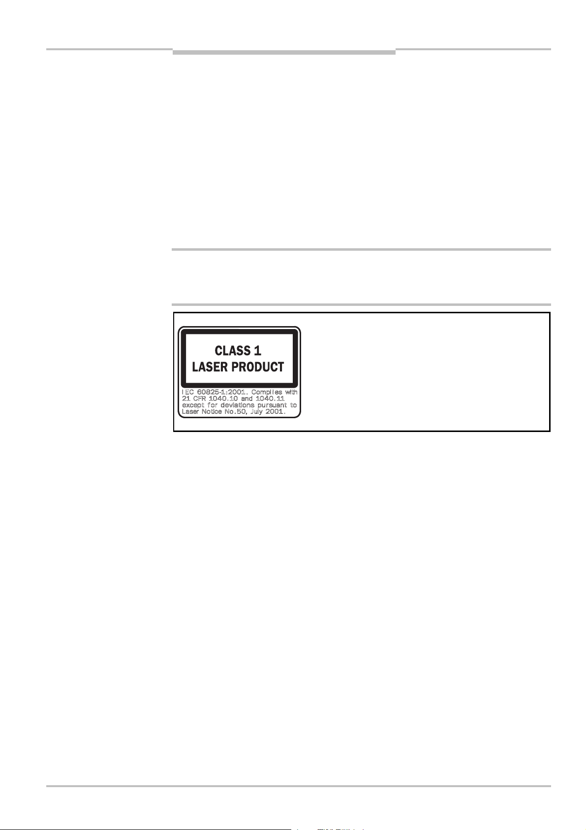
DESCRIPTION OF THE LASER WARNING LABEL:
IEC 60825<1:2001. Complies with 21 CFR 1040.10
and 1040.11 except for deviations pursuant to Laser
Notice No. 50, July 2001.
This device meets the norms: CDRH 21 CFR 1040.10 and 1040.11 as well as
IEC 60825<1 edition 1.2:2001<08. There the following note is required: “Caution — if
devices for operation or adjustment different to those given here are used or other
procedures are employed, hazardous exposure to radiation may occur!”
During the mounting, installation and usage of the S200, observe the standards and
directives applicable in your country. You will find an overview of the most important
regulations in section 2.6 “Applicable directives and standards” on page 12.
The national/international rules and regulations apply to the installation, commissioning,
use and periodic technical inspections of the S200 safety laser scanner, in particular …
– Machinery Directive 98/37/EC.
– Work Equipment Directive 89/655/EEC.
– the work safety regulations/safety rules.
– other relevant health and safety regulations.
Manufacturers and operators of the machine on which the S200 is used are responsible
for obtaining and observing all applicable safety regulations and rules.
The notes, in particular the test notes (see chapter 8 “Commissioning” on page 50) in
these operating instructions (e.g. on use, mounting, installation or integration into the
machine controller) must be observed.
8011692/02-06-06 © SICK AG • Industrial Safety Systems • Germany • All rights reserved 9
Page 10

Chapter 2 Safety Laser Scanner
On safety
S200
Changes to the configuration of the devices can degrade the protective function. After
very change to the configuration you must therefore check the effectiveness of the
e
protective device. The person who makes the change is also responsible for the correct
protective function of the device. When making configuration changes, please always
use the password hierarchy provided by SICK to ensure that only authorised persons
make changes to the configuration. The SICK service team is available to provide
assistance if required.
The tests must be carried out by specialist personnel or specially qualified and
authorised personnel and must be recorded and documented to ensure that the tests
can be reconstructed and retraced at any time.
The operating instructions must be made available to the operator of the machine where
the S200 is used. The machine operator is to be instructed in the use of the device by
specialist personnel and must be instructed to read the operating instructions.
The external voltage supply of the devices must be capable of buffering brief mains
voltage failures of 20 ms as specified in EN 60204. Suitable power supplies are
available as accessories from SICK (see section 12.3 “Accessories/spare parts” on
page 75).
Enclosed with these operating instructions is a checklist for checking by the
manufacturer and OEM (see section 13.2 “Manufacturer’s checklist” on page 77). Use
this checklist when checking the plant that is protected with the S200.
The term “dangerous state”
The dangerous state (standard term) of the machine is always shown in the drawings and
diagrams of this document as a movement of a machine part. In practical operation, there
may be other dangerous states:
machine movements
vehicle movements
electrical conductors
visible or invisible radiation
a combination of several risks and hazards
10 © SICK AG • Industrial Safety Systems • Germany • All rights reserved 8011692/02-06-06
Page 11

Safety Laser Scanner Chapter 2
Tab.1:
Overview on disposal
S200
On safety
2.5 Environmental protection
he S200 safety laser scanner is constructed in such a way that it adversely affects the
T
environment as little as possible and uses only a minimum of power and natural
resources.
At work, always act in an environmentally responsible manner.
2.5.1 Disposal
Unusable or irreparable devices should always be disposed as per the applicable national
regulations on waste disposal (e.g. European waste code 16 02 14).
Notes
WARNING
We would be pleased to be of assistance on the disposal of this device. Contact your
local SICK representative.
Information on the individual materials in the S200 is given in chapter 11 “Technical
specifications” on page 65.
2.5.2 Separation of materials
Only appropriately trained personnel are allowed to separate materials!
Caution is required when dismantling devices. There is a risk of injuries.
Before you send the devices for appropriate recycling, it is necessary to separate the
different materials in the S200.
Separate the housing from the rest of the parts (in particular the circuit boards).
Send the separated parts for recycling as appropriate (see Tab. 1).
by components
Components Disposal
Product
Housing Metal recycling (aluminium)
Motor bracket Metal recycling (zinc die-cast housing)
Optics cover Plastic recycling
Circuit boards, cables, connectors and
electrical connecting pieces
Packaging
Cardboard, paper Paper/cardboard recycling
Polyethylene packaging Plastic recycling
Electronic recycling
8011692/02-06-06 © SICK AG • Industrial Safety Systems • Germany • All rights reserved 11
Page 12

Chapter 2 Safety Laser Scanner
On safety
S200
2.6 Applicable directives and standards
The most important directives and standards, valid for the use of opto-electronic protective
devices in Europe, are listed below. Further regulations may be of importance to you,
depending on the application. You can obtain further information of machine-specific
standards from national institutions (e.g. DIN, BSI, AFNOR etc.), the authorities or your
trade association.
If you operate the machine or vehicle in a country outside the European Union, please
contact the manufacturer of the plant and the local authorities and obtain information on
the regulations and standards applicable there.
Application and installation of protective devices
Machinery Directive 98/37/EC, e.g.:
Safety of machinery — Basic concepts, general principles for design (EN 12100)
Industrial automation systems — Safety of integrated manufacturing systems —- Basic
requirements (ISO 11161)
Safety of machinery — Electrical equipment of machines — Part 1: General requirements
(IEC/EN 60204)
Safety of machinery. Safety distances to prevent hazardous points being reached by the
upper limbs (EN 294, IEC 13852)
Safety requirements for robots (EN 775, ISO 10218)
Safety of industrial trucks. Driverless trucks and their systems (DIN/EN 1525)
Safety of machinery — The positioning of protective equipment in respect of approach
speeds of parts of the human body (EN 999, ISO 13855)
Safety of machinery — Principles for risk assessment (EN 1050, ISO 14121)
Safety of machinery — Safety-related parts of control systems — Part 1: General
principles for design (EN 954 part 1, ISO 13849 part 2)
Safety of machines — electro-sensitive protective equipment — part 1: General
requirements (IEC/EN 61496<1) as well as part 3: Special requirements for AOPDDR
(IEC 61496<3)
Safety of machinery — Application of protective equipment to detect the presence of
persons (IEC/TS 62046)
Foreign standards, for example:
Performance Criteria for Safeguarding (ANSI B11.19)
Machine tools for manufacturing systems/cells (ANSI B11.20)
Safety requirements for Industrial Robots and Robot Systems (ANSI/RIA R15.06)
Safety Standard for guided industrial vehicles and automated functions of named
industrial vehicles (ANSI B56.5)
Recommendation
Please request our brochure on this subject “Safe Machines with opto-electronic protective
devices”.
12 © SICK AG • Industrial Safety Systems • Germany • All rights reserved 8011692/02-06-06
Page 13
Safety Laser Scanner Chapter 3
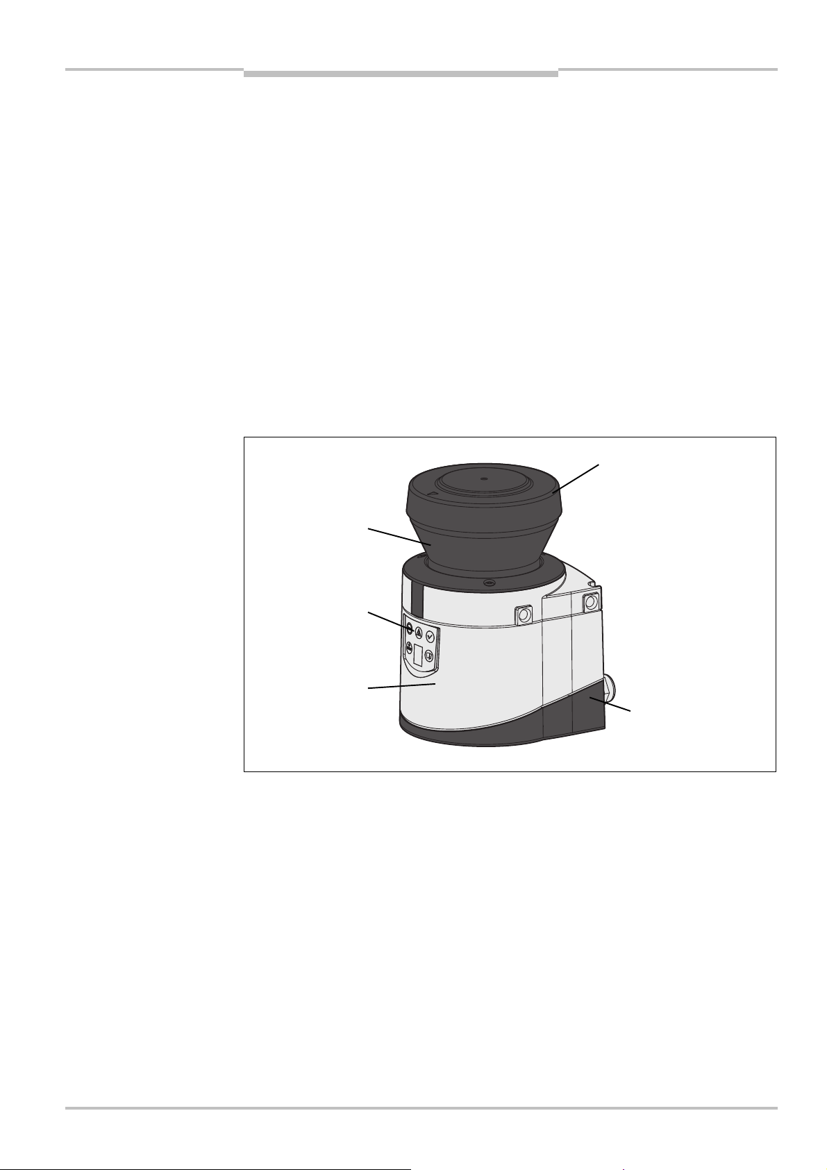
Fig.1:
Device components
Optics cover
System plug
Sensor
display
Window for light
S200
Product description
3 Product description
This chapter provides information on the special features and properties of the S200
safety laser scanner. It describes the construction and the operating principle of the
device.
Please read this chapter before mounting, installing and commissioning the device.
3.1 Device components
The S200 safety laser scanner comprises three components:
the sensor with the opto-electronic acquisition system, the LEDs and the 7<segment
display
the optics cover with the window for the light output
the system plug with the configuration memory (the system plug contains all electrical
connections)
the system plug with all electrical connections
output
LEDs and 7$segment
3.2 Special features
270° scanning angle
the surrounding contour can be monitored (contour change can e.g. be the opening of a
door to the outside)
integrated external device monitoring (EDM)
integrated restart interlock/restart interlock delay for which the parameters can be set
status display with LEDs and 7<segment display
minimum response time 80 ms
configuration using PC or notebook with SICK Configuration & Diagnostic Software
increased resilience to external light and dust due to highly effective dazzle and particle
algorithms
8011692/02-06-06 © SICK AG • Industrial Safety Systems • Germany • All rights reserved 13
Page 14

Chapter 3 Safety Laser Scanner
Tab.2:
Functions of the
Product description
S200
S200 functions
S200
Functions
Protective field range 1.5 m
Warning field width
1)
8 m
Object resolution 30/40/50/70 mm
ield sets 1
F
Programmable monitoring cases 1
Pairs of output signal switching devices (OSSDs) 1
Source switching current of the OSSDs 250 mA
Application diagnostic output “Warning field
interrupted”
Application diagnostic output
“Error/contamination”
Application diagnostic output “Reset required”
External device monitoring (EDM)
Restart interlock/delay
Stand-by mode
3.3 Function
The S200 safety laser scanner operates correctly as a protective device only if the
following conditions are met:
The control of the machine, system or vehicle must be electrical.
After integration in the control it must be possible to transfer the dangerous machine,
system or vehicle state to a safe state using the OSSDs on the S200 at any time, i.e.
before a person has reached the hazardous point or hazardous area.
The S200 must be mounted and configured such that it detects objects as they enter
the hazardous area (see chapter 4 “Mounting” on page 27 and chapter 8
“Commissioning” on page 50).
14 © SICK AG • Industrial Safety Systems • Germany • All rights reserved 8011692/02-06-06
1)
Warning field range with a reflectivity of 30% (see Fig. 41 “Diagram of scanning ranges for various
reflectances” on page 61).
Page 15

Safety Laser Scanner Chapter 3
Fig.2:
Principle of operation,
Fig.3:
Principle of operation,
S
Receive pulse
Send pulse
S300
E
S200
Product description
3.3.1 Principles of operation
The S200 is an optical sensor that scans its surroundings in two dimensions using infrared
laser beams. It is used to monitor hazardous areas on machines or vehicles.
time of flight measurement
by the S200
t
The S200 works on the principle of time of flight measurement. It sends out very short
pulses of light (S). At the same time an “electronic stopwatch” is started. When the light is
incident on an object, it is reflected and received by the safety laser scanner (E). From the
time between sending and reception (t) the S200 calculates the distance to the object.
rotation of the S200
In the S200 there is also a mirror rotating at constant speed that deflects the light pulses
such that they cover an arc of 270° . In this way an object can be detected in the
protective field within 270°. The first beam of a scan starts at S45° relative to the back
of the scanner.
The S200 sends a pulse of light with an angular resolution of 0.5°. In this way resolutions
from 30 to 70 mm can be achieved independent of the length of the protective field !
8011692/02-06-06 © SICK AG • Industrial Safety Systems • Germany • All rights reserved 15
Page 16
Chapter 3 Safety Laser Scanner
Fig.4:
Protective field,
Product description
S200
Due to its active scanning principle, the S200 does not require receivers or reflectors. This
as the following advantages:
h
Your installation effort is lower.
You can easily adapt the monitored area to the hazardous area on a machine.
In comparison with contact sensors, electro-sensitive scanning is nearly wear-free.
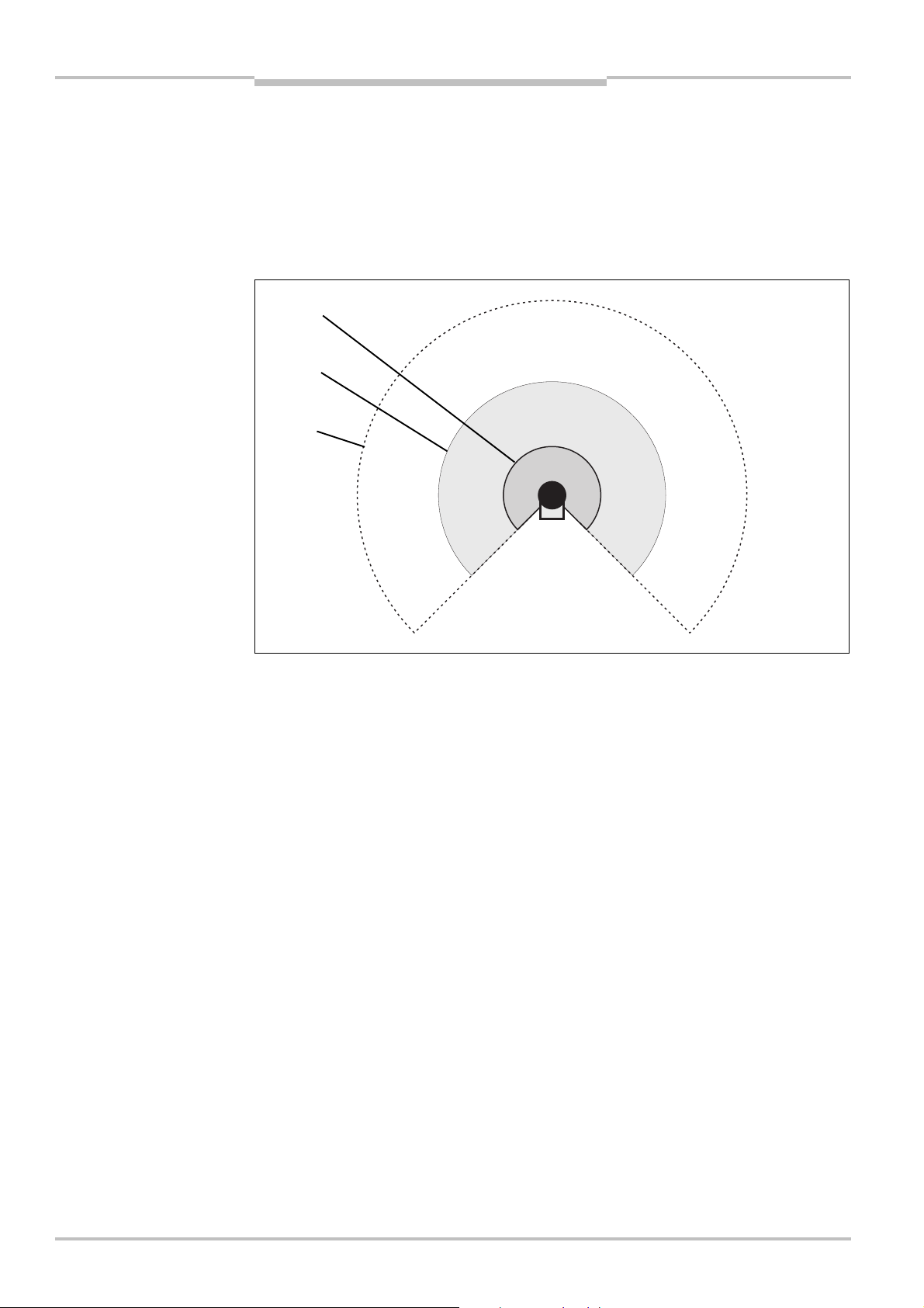
3.3.2 Field set comprising of protective field and warning field
warning field and distance
measuring range
The S200 protects the hazardous area on a machine or a vehicle using the protective
field . As soon as the safety laser scanner detects an object in the protective field, it
switches the OSSDs to the OFF state and thus initiates the shutdown of the machine or
stop of the vehicle.
You can define the warning field such that the safety laser scanner detects an object
before the actual hazardous area and e.g. triggers a warning signal.
The maximum distance at which the safety laser scanner can detect an object is defined
by the distance measuring range .
Protective field and warning field form a pair, the so-called field set.
With the aid of the CDS you can configure the field set and transfer it to the S200. If the
hazardous area to be monitored changes, then you can re-configure the S200 in software
without additional mounting effort.
16 © SICK AG • Industrial Safety Systems • Germany • All rights reserved 8011692/02-06-06
Page 17
Safety Laser Scanner Chapter 3
Fig.5:
Hazardous area
Fig.6:
Point-of-operation
Protective field
Warning field
S200
Product description
3.4 Applications
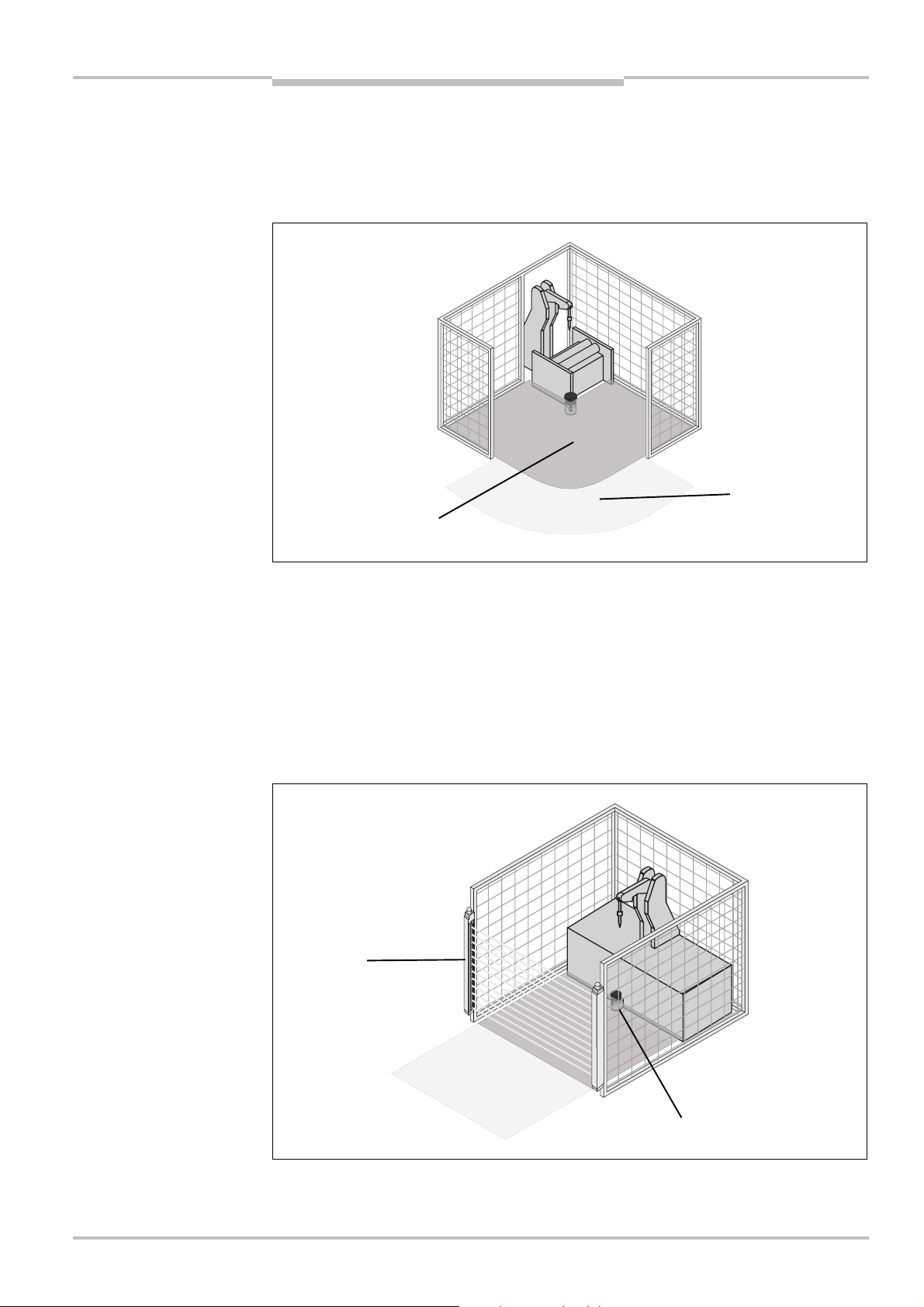
3.4.1 Stationary applications
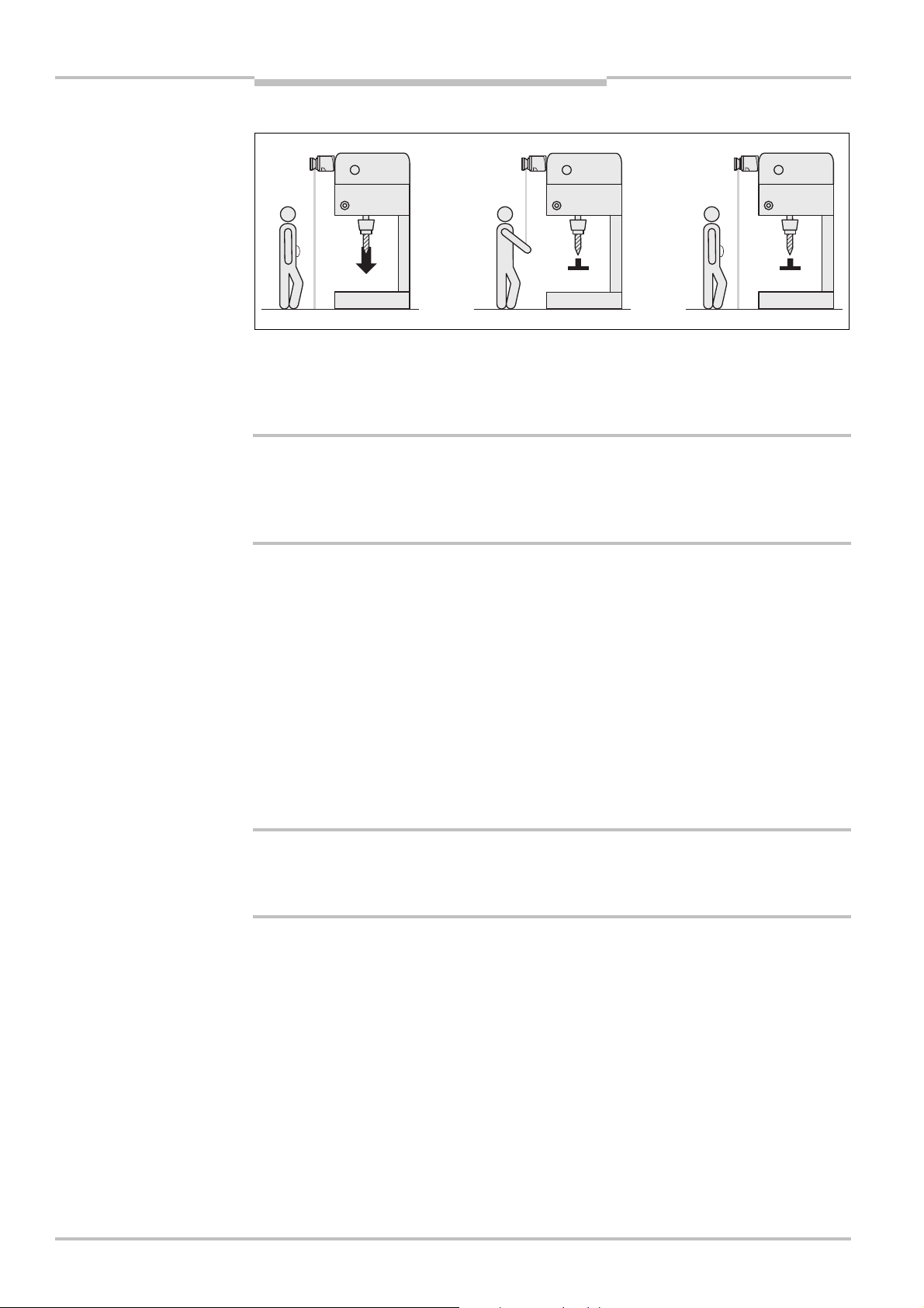
Hazardous area protection
protection with one
monitored area
guarding
On stationary machines, the S200 switches the output signal switching devices (OSSDs) to
the OFF state if the protective field is interrupted. The S200 initiates the shutdown of the
machine or the shutdown of the dangerous state.
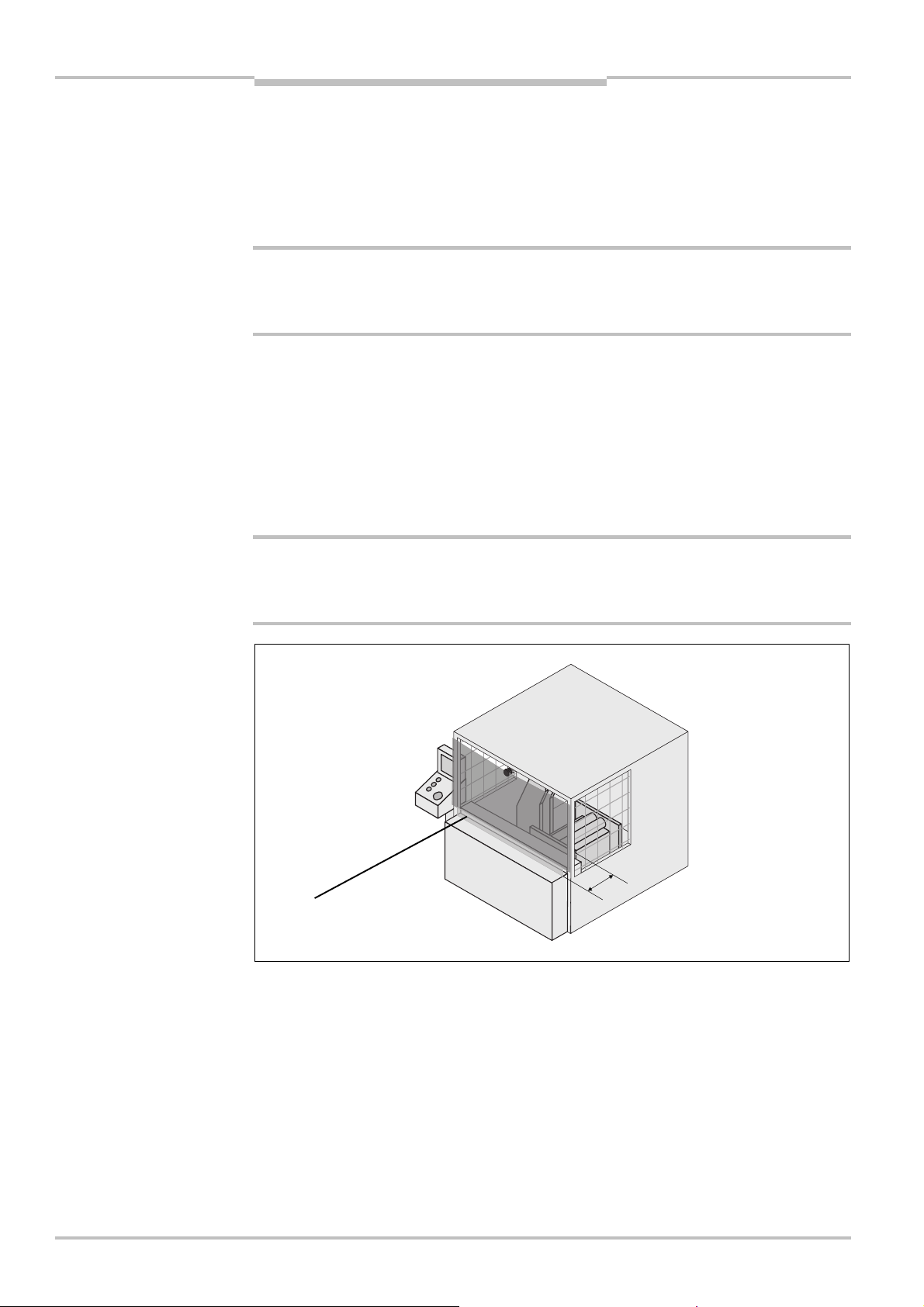
Point-of-operation guarding
The S200 safety laser scanner can be used to prevent starting or restarting as long as
there are persons in the hazardous area. The machine can only be started or restarted if
the S200 does not detect any object in the protective field. This is particularly important
for system interiors that can only be seen with difficulty from the outside, or cannot be
seen at all.
8011692/02-06-06 © SICK AG • Industrial Safety Systems • Germany • All rights reserved 17
Page 18
Chapter 3 Safety Laser Scanner
Fig.7:
Hazardous point
Fig.8:
Access protection
Contour
Contour of the floor
Protective
Protective
Product description
S200
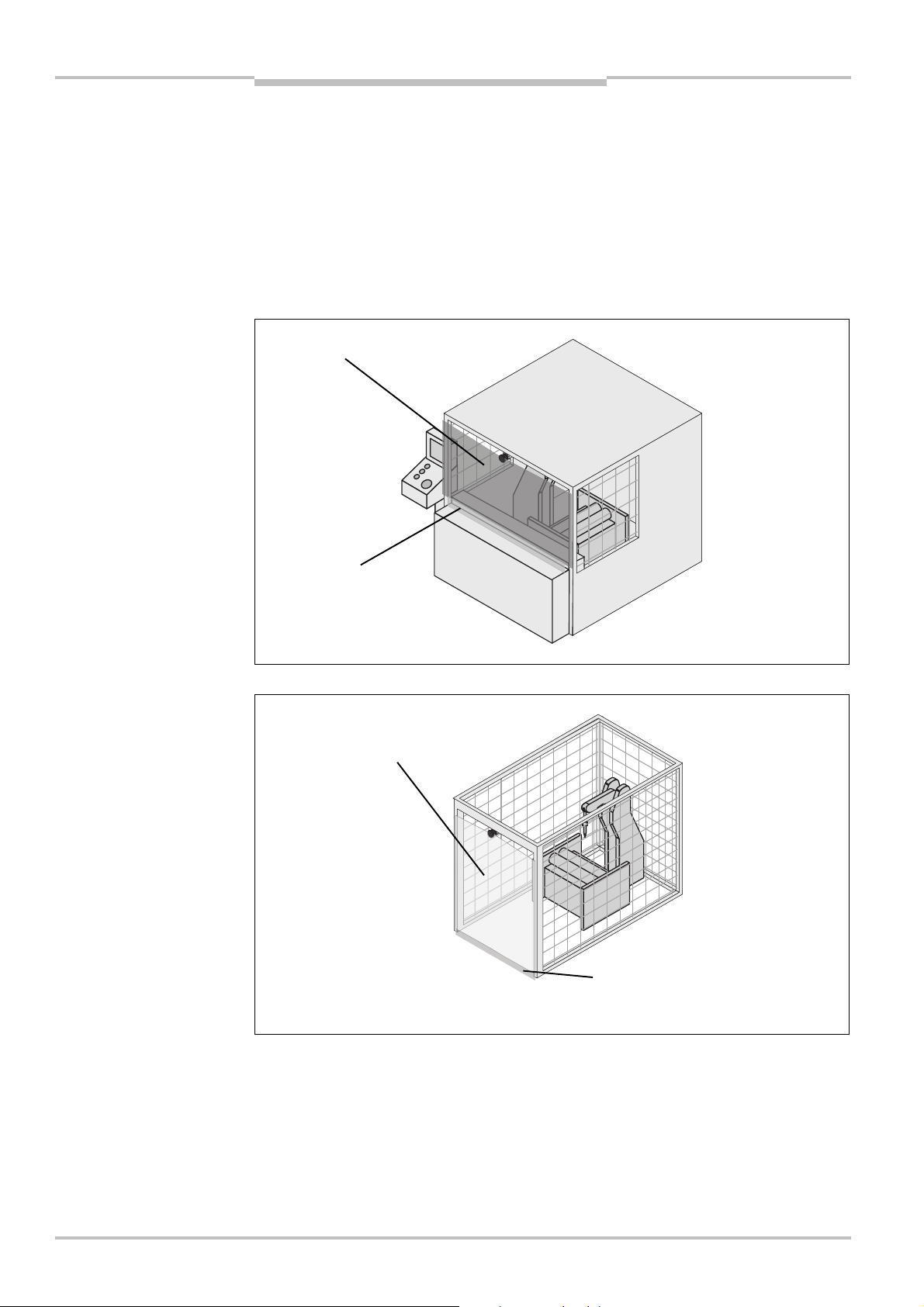
In this application the S200 does not have a stop function. The primary protective
unction that stops the dangerous movement is provided in the example by a light
f
curtain , while the S200 monitors the restarting of the machine.
Hazardous point protection (vertical operation)
The S200 can used be used vertically to trigger stopping of the dangerous movement.
ompared to horizontal protection, the area to be protected in front of the machine or
C
system can be reduced. Hazardous point protection is necessary if the operator is near the
dangerous state of the machine. Hand protection is required to protect the hazardous
point.
protection
field
as reference
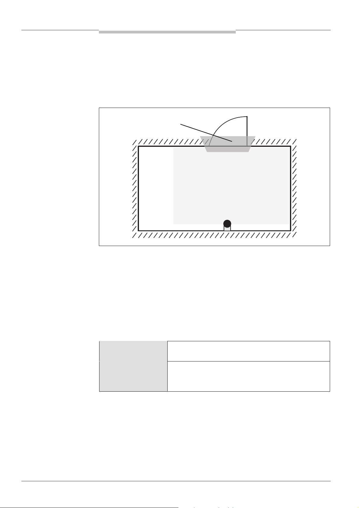
Access protection (vertical operation)
field
as reference
18 © SICK AG • Industrial Safety Systems • Germany • All rights reserved 8011692/02-06-06
You can also use the S200 vertically for access protection. Access protection can be used
when the access to the machine can be defined by physical means. In the case of access
protection, the S200 detects the entry of a person, but not presence in the hazardous area
(no point-of-operation protection).
Page 19
Safety Laser Scanner Chapter 3
Fig.9:
Reading protective
Protective field
S200
Note
Product description
3.4.2 Mobile applications
The S200 can be used both on manually controlled vehicles, e.g. fork lift trucks, and also
on automated guided vehicles (AGV) or trolleys.
You can use the S200 on vehicles, e.g. to protect the route of a vehicle through a factory
building. If there is a person or an obstacle in the hazardous area, the S200 ensures that
the vehicle reduces the velocity and stops if necessary.
The safety level of the S200 corresponds to category 2 according to EN 954-1. It is only
allowed to be used in corresponding applications.
3.5 Configurable functions
3.5.1 Field set
Configuration of the protective field and warning field
With the aid of the CDS you can configure the field set, which comprises a protective field
and a warning field. During this process you configure the shape and size of the protective
field and the warning field. You can realise any field shape required.
Note
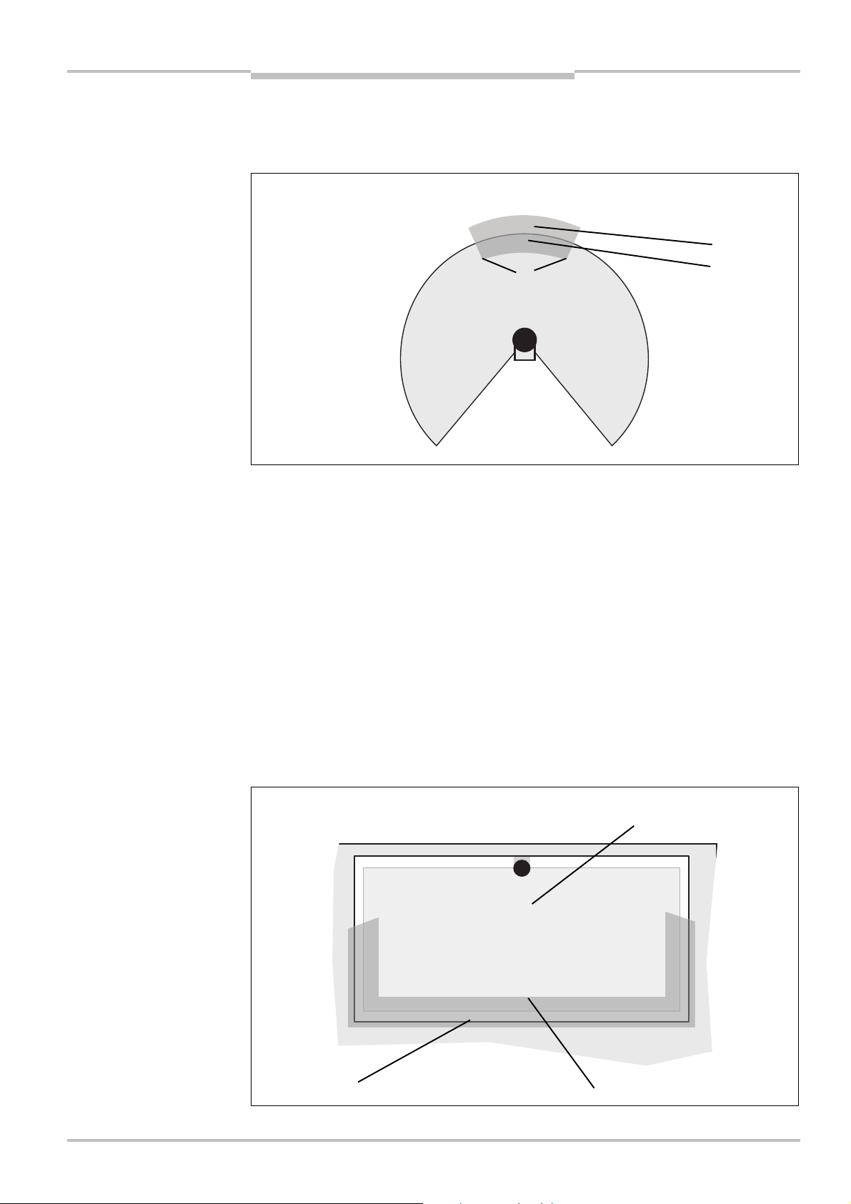
The area to be monitored is scanned radially by the S200. The S200 cannot see through
objects during this process. The area behind objects that are in the area to be monitored
(pillars, grilles, etc.) can thus not be monitored.
Protective field and warning field can cover up an angle of up to 270° and have different
radial scanning ranges depending on the resolution configured (see Tab. 3 on page 20).
field or warning field
WARNING
Check the configured protective field!
Prior to commissioning the machine or vehicle, check the configuration of the protective
field using the instructions in chapter 8 “Commissioning” on page 50 and using the
checklist on page 77.
Protective field or warning field suggested by the safety laser scanner
The CDS can suggest the protective field or warning field. The safety laser scanner scans
the visible room contour several times. From the data obtained the CDS suggests the
contour and size of the field.
8011692/02-06-06 © SICK AG • Industrial Safety Systems • Germany • All rights reserved 19
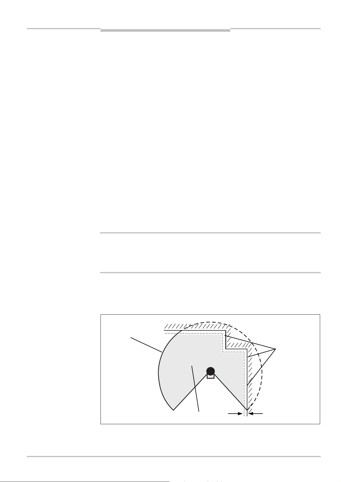
In those places at which the room contour is smaller than the maximum protective field
range (e.g. at ), the protective field corresponds to the room contour.
Page 20

Chapter 3 Safety Laser Scanner
Tab.3:
Maximum protective
Product description
S200
Note
WARNING
The measuring error tolerances for the S200 are automatically subtracted from the
rotective field size. As a result the protective field is slightly smaller than the surface
p
covered .
In those places where the room contour is larger than the protective field range , the
protective field corresponds to the possible scanning range (see Tab. 3 on page 20).
Check the protective field suggested!
The protective field suggested by the CDS is not a replacement for the calculation of the
safety distance. Calculate the safety distance based on the description in chapter 4
“Mounting” on page 27. Prior to commissioning the application, check the configuration of
the protective field using the instructions in chapter 8 “Commissioning” on page 50 and
using the checklist on page 77.
In the CDS field set editor, you can also request a suggestion for the protective field.
3.5.2 Application and resolution
With the aid of the CDS you can configure the S200 for use on a stationary or mobile
application. Also set the resolution of the S200.
The maximum protective field range depends on the resolution set. The following table
shows the related maximum protective field range at the resolutions that can be set:
field ranges at different
resolutions
Notes
Resolution Maximum protective field range
30 mm 1.25 m
40, 50, 70 mm 1.5 m
The maximum protective field range of the S200 must be sufficient to cover the
calculated protective field size including the necessary supplements (see section 4.1.1
“Protective field size” on page 28).
The warning field can be configured to up to 8 m for all resolutions. The detection
capability of the warning field is dependent on the remission of the objects to be
detected (see Fig. 41 “Diagram of scanning ranges for various reflectances” on
page 61).
20 © SICK AG • Industrial Safety Systems • Germany • All rights reserved 8011692/02-06-06
Page 21
Safety Laser Scanner Chapter 3
Fig.10:
Schematic diagram
Fig.11:
Contour as reference
Contours of the machine opening
Protective field
Contour segment
S200
of contour as reference
Product description
3.5.3 Using the contour as a reference
In addition to the protective field, the S200 can also monitor a contour (e.g. the floor in
vertical applications or the walls in horizontal applications).
for vertical operation
Note
For contour monitoring you define a contour segment . The contour segment comprises
a positive and a negative tolerance band.
The OSSDs on the S200 change to the OFF state if …
there is an object in the protective field.
the monitored surrounding contour is no longer in the tolerance band (e.g. if a door is
opened or if the position of the S200 is changed).
You can define any number of contour segments. The contour segments must not be
narrower than the configured resolution. At the points where a contour has been
configured as a reference you cannot define a warning field.
You define the contour as a reference in the CDS field set editor.
Vertical operation
In vertical operation (for access protection and hazardous point protection) according to
IEC/EN 61496<3 you must always configure the protective field with the contour as
reference function.
8011692/02-06-06 © SICK AG • Industrial Safety Systems • Germany • All rights reserved 21
Page 22
Chapter 3 Safety Laser Scanner
Fig.12:
Contour as reference
Tab.4:
Behaviour of the
Door as reference
Product description
S200
Recommendation
for horizontal operation
Use lateral, vertical boundaries of the opening (e.g. door frame) and the floor as reference.
f in this case the position of the S200 is changed in one or more planes, the distance to
I
the reference changes and the S200 switches its OSSDs to the OFF state.
Horizontal operation
On horizontal operation, you can also use the contour as reference function, e.g. so that if
door is opened (change to the room contour) the OSSDs on the S200 are placed in the
a
OFF state.
S200 on a contactor
malfunction
Notes
3.5.4 External device monitoring (EDM)
After every interruption to the protective field and prior to restarting the machine, the
external device monitoring monitors the switching devices operated by the OSSDs (e.g.
contactors). In this way the external device monitoring detects whether, e.g. the (positively
guided) contacts on the contactors connected are in the OFF position.
The machine is only allowed to start if both contactors were in the OFF position before,
that is they were deactivated.
The table shows how the S200 reacts if the external device monitoring detects a contactor
malfunction:
Without internal restart
interlock
With restart interlock The S200 switches its OSSDs to the OFF state.
You can configure the external device monitoring in the CDS.
You will find examples on the connection of the external device monitoring in section 6.2
“Connection diagrams” on page 48.
If you do not use the external device monitoring function, leave the inputs disconnected
(see section 5.1.1 “Pin assignment on the system plug” on page 44).
The system locks completely (lock-out).
The error message appears in the 7< segment display.
The LED
The error message appears in the 7<segment display.
is illuminated.
22 © SICK AG • Industrial Safety Systems • Germany • All rights reserved 8011692/02-06-06
Page 23

Safety Laser Scanner Chapter 3
S200
WARNING
Product description
3.5.5 Application diagnostic output “Error/contamination”
The S200 has a configurable application diagnostic output. The following configuration
features are available in the CDS:
window for light output contaminated
error
window for light output contaminated or error
inactive
3.5.6 Restart
You can configure the restart behaviour of the S200 as follows:
without restart interlock
with restart delay
with restart interlock
It is imperative that you configure the S200 with restart interlock if the protective field
can be left to approach the hazardous point or if a person cannot be detected at every
point in the hazard area for the S200!
During the assessment, pay attention to whether the protective field can be left in the
direction of the hazardous point, to areas that are unprotected due to the mounting and
the unprotected near range of the S200 (see section 4.5 “Methods of preventing
unprotected areas” on page 36).
Configuration of the S200 without restart interlock
After the OSSDs on the S200 have been switched to the OFF state due to an object in the
protective field, the OSSDs are re-enabled again immediately when there is no longer an
object in the active protective field.
This configuration is only allowed …
if an external restart interlock is realised on the machine controller
or
if the protective field cannot be left in the direction of the hazardous point and if people
can be detected by the S200 at every point in the hazardous area!
Restart delay for mobile applications
In mobile applications you can configure a restart delay from 2 to 60 seconds on the
S200. The OSSDs on the S200 change to the ON state if there is no object in the
protective field for the duration given.
This configuration is only allowed if the protective field cannot be left in the direction of the
hazardous point and if a person can be detected by the S200 at every point in the
hazardous area!
8011692/02-06-06 © SICK AG • Industrial Safety Systems • Germany • All rights reserved 23
Page 24
Chapter 3 Safety Laser Scanner
Fig.13:
Schematic outline of
the operation with restart
interlock
Product description
S200
Configuration of the S200 with restart interlock
WARNING
Note
The OSSDs on the S200 change to the OFF state to trigger a machine or vehicle stop as
soon as there is an object in the protective field . They do not change to the ON state ,
even if there is no longer an object in the protective field. The OSSDs only change to the
ON state if the operator operates the control switch for restart or reset.
Place the control switch for restart or reset in a suitable place!
Place the control switch for restart or reset outside the hazardous area such that it cannot
be operated by a person in the hazardous area. Ensure that the person who operates the
control switch has a full view of the hazardous area.
Reset
The reset function is often also called “preparation for restart”. In these operating
instructions the term reset is used.
If you want to activate the restart interlock on the S200 (internal) and also a restart
interlock on the machine (external), then each restart interlock has its own control switch.
After operating the control switch for the internal restart interlock (with protective field
unoccupied) …
the S200 switches its OSSDs to the ON state.
the LED
The external restart interlock prevents the machine from restarting. After resetting the
S200 the operator must press the control switch to restart the machine controller.
on the safety laser scanner illuminates green.
24 © SICK AG • Industrial Safety Systems • Germany • All rights reserved 8011692/02-06-06
WARNING
Notes
Ensure that the correct sequence is followed!
The controller must be realised such that the machine only restarts if the S200 is first
reset and then the control switch for restarting the machine controller is operated.
You will find examples on the connection of the internal restart interlock in chapter 6.2
“Connection diagrams” on page 48.
If you do not use the internal restart interlock, leave the inputs disconnected (see
section 5.1.1 “Pin assignment on the system plug” on page 44).
You can configure the type of restart in the CDS.
Page 25

Safety Laser Scanner Chapter 3
Tab.5:
Recommended
S200
WARNING
Product description
3.5.7 Multiple sampling
If multiple sampling is set, an object must be scanned several times before the S200
switches its OSSDs to the OFF state. In this way you can reduce the probability that
welding sparks, insects or other particles, result in the shutdown of the plant.
If a multiple sampling of 3 is configured, for instance, an object must be detected three
times in succession before the S200 switches the OSSDs to the OFF state.
he total response time is increased by the multiple sampling!
T
With a multiple sampling greater than 2, note that you must add a supplement to the basic
response time (see section 11.2 “OSSD response times” on page 61)!
On the S200, a multiple sampling of 2 is the minimum setting. You can set the multiple
sampling to up to 16 with the aid of the CDS.
multiple sampling
Recommendation
Recommendation
Recommended multiple sampling Application
2 times Stationary under clean ambient conditions
2 … 4 times Mobile
4 … 8 times Stationary under dusty ambient conditions
Using multiple sampling you can increase the availability of a plant.
You can configure multiple sampling in the CDS.
3.5.8 Stand-by mode
If, in mobile applications, vehicles are not moved for a time, the OSSDs and the laser on
the S200 can be switched off. In this way the power consumption of the device is reduced.
Use this function if, e.g. you use several vehicles and do not move them for a time.
A dedicated STBY single-channel input is provided for switching to the stand-by mode (see
section 5.1.1 “Pin assignment on the system plug” on page 44).
3.5.9 Naming applications and laser scanners
A name can be assigned to the application configured and to the laser scanner(s). The
names are saved in the devices after the configuration is transferred. The name chosen
may be, for example, the identifier for the vehicle, system or the machine.
You enter the application name and the name of the laser scanner used in the CDS.
8011692/02-06-06 © SICK AG • Industrial Safety Systems • Germany • All rights reserved 25
Page 26
Chapter 3 Safety Laser Scanner
Fig.14:
Status indicators on
Product description
S200
3.6 Indicators and outputs
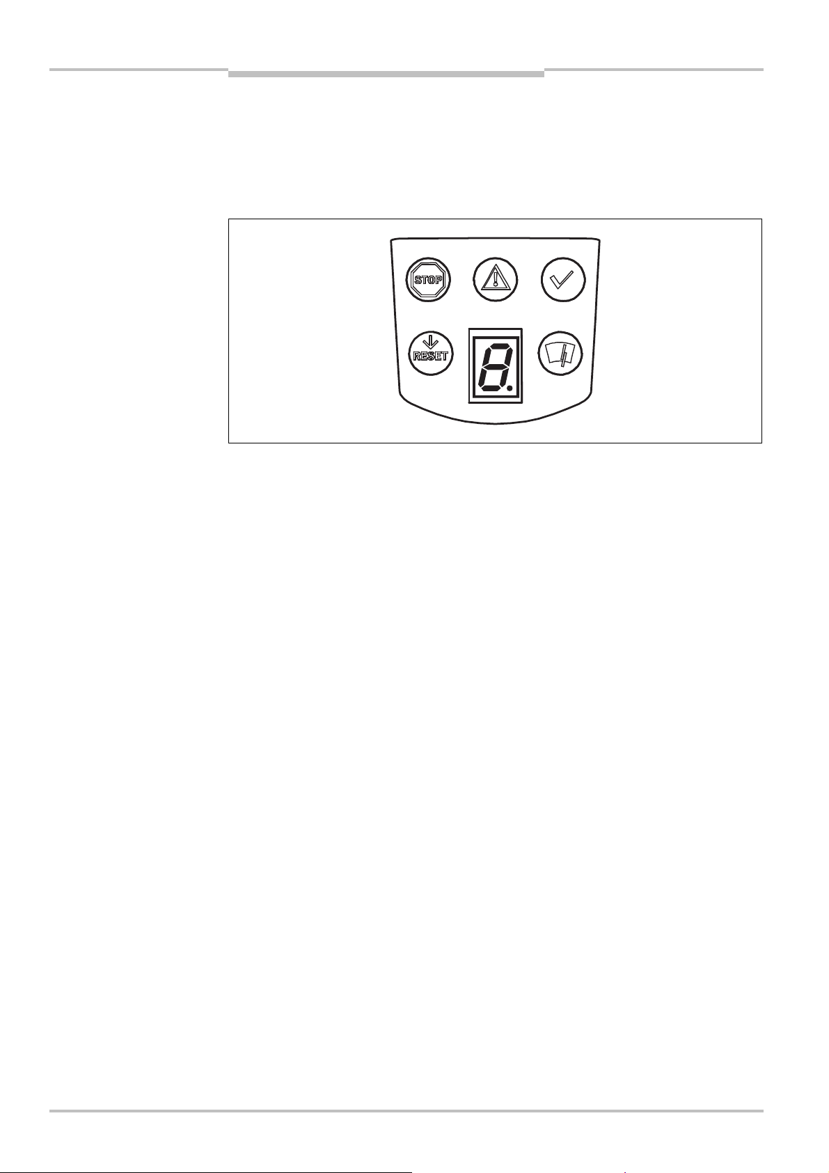
3.6.1 LEDs and 7Csegment display
The LEDs and the 7<segment display indicate the operational status of the S200. They are
on the front face of the safety laser scanner.
the S200
Note
The symbols have the following meaning:
OSSDs in the OFF state (e.g. in case of object in the protective field, monitored contour
changed, reset required, lock-out)
Warning field interrupted (object in warning field)
OSSDs in the ON state (no object in protective field)
Reset required
Optics cover contaminated
3.6.2 Outputs
Using the outputs on the S200 you shutdown the dangerous state on a machine, a plant or
a vehicle and evaluate the operational status of the S200. The S200 has the following
outputs:
OSSDs
application diagnostic output “Warning field interrupted”
application diagnostic output “error/contamination”
application diagnostic output “Reset required”
The outputs are fed out at the system plug (see section 5.1 “System connection” on
page 43).
All outputs are only allowed to be used for the purpose specified. Note that the signals at
the application diagnostics outputs for “warning field”, “contamination of the optics
cover/error” and “reset required” are single-channel and therefore are not allowed to be
used for tasks related to safety. For this reason the warning field is not allowed to be used
for tasks related to personnel protection.
26 © SICK AG • Industrial Safety Systems • Germany • All rights reserved 8011692/02-06-06
Page 27

Safety Laser Scanner Chapter 4
S200
Mounting
4 Mounting
This chapter describes the preparation and completion of the mounting of the S200 safety
laser scanner. Mounting requires three steps:
definition of the application and the necessary mounting location for the laser scanner
calculation of the protective field size
mounting the safety laser scanner with or without mounting kits
No protective function without sufficient safety distance!
WARNING
Only if you configure the protective field such that there is an adequate safety distance to
the hazardous area, is protection by the S200 ensured.
Notes
Mount the S200 in a dry place and protect the device from dirt and damage.
Avoid the installation of the S200 in the vicinity of strong electric fields. These can, e.g.,
be produced by welding cables, induction cables in the immediate vicinity and also by
mobile telephones operated nearby.
Ensure that there are no obstacles in the area to be monitored in the field of view of the
S200 that could cause interference or shadowing. Such shadowed areas cannot be
monitored by the S200. If there are unavoidable shadowed areas, check whether there
is a risk. Take additional safety precautions as necessary.
Keep the area to be monitored free of smoke, fog, steam or other forms of air impurities.
There must not be any condensation on the light output window. Otherwise the function
of the S200 may be impaired and incorrect switching may occur.
Avoid placing highly reflective objects in the scan plane of the S200. Examples:
Retroreflectors can affect the measurement results of the S200. Strongly reflective
objects within the protective field can blank part of the area to be monitored in certain
circumstances.
Mount the S200 such that it is not dazzled by incident sunlight. Do not position
stroboscopic and fluorescent lights or other strong light sources directly in the scan
plane as these may affect the S200 in specific circumstances.
Mark the protective field on the floor, if appropriate for the application (see
IEC/EN 61496<1, chapter 7).
Add the general protective field supplement of 100 mm to each protective field size
calculated. The maximum protective field range of the S200 must be sufficient to cover
the calculated protective field size and the necessary supplements.
The following steps are necessary after mounting and installation:
completing the electrical connections (chapter 5 “Electrical installation”)
configuration of the protective field (chapter7 “Configuration”)
commissioning and checking of the installation (chapter 8 “Commissioning”)
checking the function and safe shutdown (section 8.3 “Test notes”)
8011692/02-06-06 © SICK AG • Industrial Safety Systems • Germany • All rights reserved 27
Page 28

Chapter 4 Safety Laser Scanner
Fig.15:
Horizontal stationary
S
Mounting
S200
4.1 Stationary application in horizontal operation
his type of protective device is suitable for machines and systems on which, e.g. a
T
hazardous area is not completely enclosed by a guard.
application
Note
WARNING
For a horizontal stationary application determine …
the protective field size to observe the necessary safety distance.
the height of the scan plane.
the restart behaviour.
measures to protect any areas not covered by the S200.
Once you have defined the protective field size, mark the boundaries of the protective field
on the floor. In this way you will make the protective field boundaries visible for the
operator and ease subsequent testing of the shape of the protective field.
4.1.1 Protective field size
The protective field must be so configured that a safety distance (S) to the hazardous area
is maintained. This safety distance ensures that the hazardous point can only be reached
after the dangerous state of the machine has been completely stopped.
You can operate the S200 in stationary horizontal operation with 30, 40, 50 or 70 mm
resolution. The maximum protective field range for the S200 is given by the resolution.
Ensure that a human leg can be detected with 70 mm resolution!
As per EN 999, mount the scan planes for horizontal stationary applications with 70 mm
resolution at least 300 mm above the floor (see “Height of the scan plane at 70 mm
resolution” on page 31).
28 © SICK AG • Industrial Safety Systems • Germany • All rights reserved 8011692/02-06-06
Page 29

Safety Laser Scanner Chapter 4
Fig.16:
Safety distance S
ZG+ ZR+ CSK × (T
+ TS)
Dangerous state
S200
Mounting
M
The safety distance S depends on:
approach speed of the body or parts of the body
stopping/run-down time of the machine or system
(The stopping/run-down time is shown in the machine documentation or must be
determined by taking a measurement.)
response time of the S200
supplements for general measurement errors and any measurement errors related to
reflection
supplement for prevention of reaching over
height of the scan plane
WARNING
How to calculate the safety distance S:
First, calculate S using the following formula:
S=(K × (T
+ TS)) + ZG+ ZR+ C
M
Where …
K = Approach speed (1600 mm/s, defined in EN 999)
= Stopping/run-down time of the machine or system
T
M
= Response time of the S200 and the downstream controller
T
S
Z
= General safety supplement of the S200 = 100 mm
G
= Supplement for measurement error related to reflection
Z
R
C = Supplement for prevention of reaching over
Response time T
The response time T
of the S200
S
of the S200 depends on …
S
the basic response time of the S200.
the multiple sampling set.
See section 11.2 “OSSD response times” on page 61.
Supplement Z
for measurement error related to reflection
R
Avoid mounting retroreflectors at a distance of less than one meter from the boundary
of the protective field!
With retroreflectors positioned at a distance of less than 1 m from the boundary of the
protective field a supplement, Z
, of 200 mm must be added to the protective field.
R
8011692/02-06-06 © SICK AG • Industrial Safety Systems • Germany • All rights reserved 29
Supplement C for protection against reaching over
With a protective field installed horizontally, there is a risk that people may reach over the
protective field and in this way reach the hazardous area before the S200 shuts down the
Page 30
Chapter 4 Safety Laser Scanner
Fig.17:
Mounting variations
Tab.6:
Advantages and
C = 1200
C = 850
HD= 0
HD= 875
HSHSHD= 875
H
C = 850
Mounting
S200
dangerous state. For this reason the calculation of the safety distance must take into
ccount a supplement to prevent persons from finding themselves in a hazardous
a
situation by reaching over (see EN 294, table 1) before the S200 triggers.
The necessary supplement for the safety distance is dependent on the height of the scan
plane for the protective field. At low heights the supplement is larger than at greater
heights and .
for the scan plane
disadvantages of mounting
variations
S
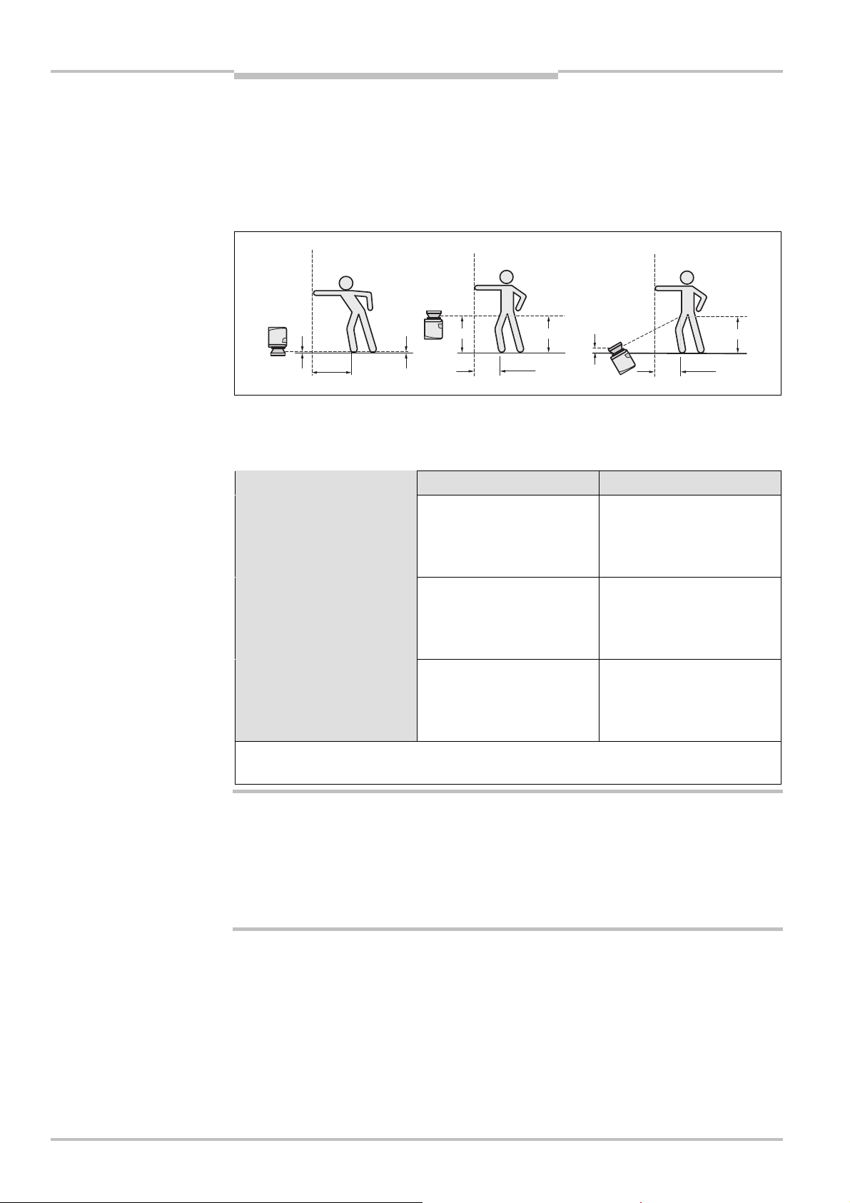
In summary there are three usual variations of mounting the scan plane for the S200. The
optimal variation depends on the related application. Tab. 6 provides assistance making
the selection.
Mounting orientation Benefit Disadvantage
Laser scanner low
(HS< 300 mm)
Inclination of the scanning
plane low (HD HS)
Laser scanner high
(HS> 300 mm)
Inclination of the scanning
plane low (HD HS)
Low external effects due to
dazzle, crawling beneath
not possible
Lower protective field
supplement C
Higher supplement C
Danger of crawling beneath
(at the front and side)
WARNING
Note
Laser scanner low
(HS< 300 mm)
Inclination of the scanner
plane high (HD> HS)
HD= Detection height
= Scanner mounting height
H
S
In case of scan planes at a height of more than 300 mm ensure that people cannot
reach the hazardous area by crawling underneath the scan plane!
If you mount the protective device higher than 300 mm, you must prevent crawling
beneath by means of additional measures. For applications that are accessible to the
public, the mounting height may need to be reduced to 200 mm (on this subject see the
appropriate regulations).
How to calculate the supplement C:
If there is enough empty space in front of your machine or plant, use 1200 mm for the
supplement C.
If the safety distance is to be kept as small as possible, calculate C using the following
formula:
C = 1200 mm – (0.4 × H
Here H
The minimum supplement C to prevent reaching over is 850 mm (arm length).
is the height at which the protective field is mounted.
D
Lower protective field
supplement C
)
D
Danger of crawling beneath
(at the front), external effect
due to dazzle possible
30 © SICK AG • Industrial Safety Systems • Germany • All rights reserved 8011692/02-06-06
Page 31

Safety Laser Scanner Chapter 4
Fig.18:
Relationship between
S200
Mounting
Height of the scan plane at 70 mm resolution
Due to the radial sampling of the protective field, the optical resolution will be lower the
urther away you get from the safety laser scanner.
f
resolution and protective
field mounting height
If you choose a resolution of 70 mm in the CDS for hazardous area protection, a human
leg may, in certain circumstances, not be detected (e.g. scan to left and right of the
bone ).
If you mount the S200 higher, the scan plane is at fibula height and the leg is also
detected with an object resolution of 70 mm .
8011692/02-06-06 © SICK AG • Industrial Safety Systems • Germany • All rights reserved 31
Page 32

Chapter 4 Safety Laser Scanner
Fig.19:
Access protection
Contour of the floor
S
Protective
Mounting
S200
4.2 Stationary vertical operation for access protection
ccess protection can be used when the access to the machine can be defined by physical
A
means. For access protection the S200 detects the entry of an entire body.
Notes
To ensure adequate access protection, a response time of 90 ms and a resolution of
70 mm or finer are required.
To protect the protective device against unadvertent adjustment or manipulation, you
must use the contour of the surroundings as a reference for the S200 (see section 3.5.3
“Using the contour as a reference” on page 21).
4.2.1 Safety distance
For access protection, a safety distance (S) must be maintained between protective field
and hazardous area. This safety distance ensures that the hazardous point can only be
reached after the dangerous state of the machine has been completely stopped.
field
as reference
The safety distance S as defined in EN 999 and EN 294 depends on:
reach or approach speed
stopping/run-down time of the machine or system
(The stopping/run-down time is shown in the machine documentation or must be
determined by taking a measurement. On request SICK service can perform a detailed
stopping/run-down measurement on your plant.)
response time of the S200
supplement C against reaching through
32 © SICK AG • Industrial Safety Systems • Germany • All rights reserved 8011692/02-06-06
Page 33

Safety Laser Scanner Chapter 4
S200
Mounting
How to calculate the safety distance S:
First, calculate S using the following formula:
T
=(K × (T
S
Where …
K = Approach speed (1600 mm/s, defined in EN 999)
Stopping/run-down time of the machine or system
T
=
M
T
= Response time of the S200
S
C = Supplement against reaching through (850 mm)
) + C
+
)
M
S
WARNING
Response time T
The total response time of the S200 must not be more than 80 ms for access
protection!
If a critical response time is exceeded (for an object diameter of 70 mm and a speed of
1.6 m/s that is 90 ms) a person may no longer be detected under certain circumstances.
In specific cases agreed with the responsible authorities higher response times may be
allowed (for example by increasing the detection time available by positioning the scanner
at an angle). In this case ensure that the areas the laser scanner cannot see are protected
by additional measures.
The response time TSof the S200 depends on …
the basic response time of the S200.
the multiple sampling set.
See section 11.2 “OSSD response times” on page 61.
of the S200
S
8011692/02-06-06 © SICK AG • Industrial Safety Systems • Germany • All rights reserved 33
Page 34
Chapter 4 Safety Laser Scanner
Fig.20:
Safety distance to
Contours
S
Mounting
S200
4.3 Stationary vertical operation for hazardous point protection
Hazardous point protection is necessary if the operator must remain near the dangerous
tate of the machine. Hand protection is required for hazardous point protection.
s
Note
WARNING
The S200 must therefore be configured with a resolution of at least 40 mm.
Never use the S200 for safety applications in which finger protection is required!
Due to the finest possible resolution of 30 mm, the S200 is not suitable for finger
protection.
To protect the protective device against unadvertent adjustment or manipulation, you
must use the contour of the surroundings as a reference for the S200 (see section 3.5.3
“Using the contour as a reference” on page 21).
4.3.1 Safety distance
For hazardous point protection, a safety distance must be observed between protective
field and hazardous point. This safety distance ensures that the hazardous point can only
be reached after the dangerous state of the machine has been completely stopped.
the hazardous area
WARNING
Prevent reaching around or reaching behind the protective field!
Always mount the laser scanner such that reaching around and behind is impossible.
Provide suitable additional precautions as necessary.
as reference
The safety distance S as defined in EN 999 and EN 294 depends on:
stopping/run-down time of the machine or system
(The stopping/run-down time is shown in the machine documentation or must be
determined by taking a measurement.)
response time of the S200
reach or approach speed
resolution of the S200
34 © SICK AG • Industrial Safety Systems • Germany • All rights reserved 8011692/02-06-06
Page 35

Safety Laser Scanner Chapter 4
S200
Mounting
How to calculate the safety distance S:
First, calculate S using the following formula:
T
= 2000 × (T
S
M
+ 8 × (d – 14 mm) [mm]
+
)
S
Where …
S = Safety distance [mm]
Stopping/run-down time of the machine or system
T
=
M
T
= Response time of the S200
S
d = Resolution of the S200 [mm]
ote
N
The reach/approach speed is already included in the formula.
If the result S is 500 mm, then use the determined value as the safety distance.
If the result S is > 500 mm, you may be able to reduce the safety distance using the
following calculation:
S = 1600 × (T
+ TS) + 8 × (d – 14 mm) [mm]
M
If the new value S is > 500 mm, then use the newly calculated value as the minimum
safety distance.
If the new value S is 500 mm, then use 500 mm as the minimum safety distance.
Notes
Response time T
The response time T
of the S200
S
of the S200 depends on …
S
the basic response time of the S200.
the multiple sampling set.
See section 11.2 “OSSD response times” on page 61.
4.4 Mobile applications
If the dangerous state is produced by a vehicle (e.g. AGV or fork lift), the hazardous area
that is produced by the movement of the vehicle is protected by the S200.
The safety level of the S200 corresponds to category 2 according to EN 954-1. It is only
allowed to be used in corresponding applications.
The S200 may only be used to protect vehicles powered by electric motor.
On automated guided systems the S200 is not allowed to be used to protect the main
direction of travel.
For vehicle protection, observe DIN/EN 1525 “Safety of industrial trucks. Driverless
trucks and their systems”.
If the application is to protect vehicles from collisions, then you may need to use
different assumptions.
8011692/02-06-06 © SICK AG • Industrial Safety Systems • Germany • All rights reserved 35
Page 36

Chapter 4 Safety Laser Scanner
Fig.21:
Unprotected areas
Fig.22:
Preventing
Mounting
S200
4.5 Methods of preventing unprotected areas
uring mounting the S200, areas may be found that are not covered by the safety laser
D
scanner ().
Prevent or secure unprotected areas!
WARNING
Mount the S200 such that there are no unprotected areas.
For mobile applications, if the vehicle is accelerated to a maximum velocity of 0.3 m/s in
less than three seconds when in operation, you must prevent personnel from entering
the unprotected areas by means of mechanical trim panels, switch strips or fitting the
S200 in the vehicle trim panels.
unprotected areas
Mount the S200 for example on a corner to prevent unprotected areas.
4.5.1 Near range
Make the near range impassible using a bar or a recess, or additionally protect the near
range (5 cm wide area in front of the optics cover) using a proximity switch with 5 cm
acquisition range. The vehicle may then be accelerated as required.
36 © SICK AG • Industrial Safety Systems • Germany • All rights reserved 8011692/02-06-06
Page 37

Safety Laser Scanner Chapter 4
Fig.23:
Prevent crawling
S200
Mounting
4.6 Mounting steps
pecial features to note during mounting:
S
WARNING
beneath, standing behind,
climbing over
Mount the S200 such that it is protected from moisture, dirt and damage.
Ensure that the entire field of view of the S200 is not restricted.
Mount the laser scanner such that the indicators are easy to see.
Always mount the S200 so that there is still enough space for mounting and removing
the system plug.
Avoid excessive shock and vibration loading on the safety laser scanner.
On applications that suffer from heavy vibration, prevent the fixing screws from coming
loose using screw locking devices.
Regularly check the tightness of the fixing screws.
Prevent personnel from being able to crawl beneath, stand behind or climb over the
protective field by means of appropriate mounting of the S200.
The origin of the scan plane is 116 mm above the bottom edge of the S200 (see
section 11.5.3 “Scan plane origin” on page 73).
There are three possible ways of fixing the S200:
direct mounting without mounting kit
mounting with mounting kit 1a or 1b
mounting with mounting kit 2 (only in conjunction with mounting kit 1a or 1b)
You will find the part numbers for the mounting kits in section 12.3.1 “Mounting kits” on
page 74.
Note
8011692/02-06-06 © SICK AG • Industrial Safety Systems • Germany • All rights reserved 37
Pay attention to the maximum torque of the M5 fixing screws on the S200 of max. 5.9 Nm.
Page 38

Chapter 4 Safety Laser Scanner
Fig.24:
Direct mounting
Fig.25:
Mounting with
M5×8
Mounting kit
1a
Threaded holes
M5×8
Mounting
S200
4.6.1 Direct mounting
The S200 has two threaded holes M5× 8 on the rear. Using them you can mount the S200
directly on the intended mounting surface. To avoid a possible tendency to vibrate, if
necessary the reference surface on the rear can be used as the third mounting point .
mounting kit 1a
Notes
During mounting, please observe the dimensional drawings in chapter “Technical
specifications” (see section 11.5 “Dimensional drawings” on page 71).
4.6.2 Mounting with mounting kit 1a or 1b
With the aid of mounting kit 1 you can mount the S200 indirectly on the mounting surface.
The mounting kit is available as mounting kit 1a without protection device for the optics
cover and as mounting kit 1b with protection device for the optics cover.
Mounting screws
38 © SICK AG • Industrial Safety Systems • Germany • All rights reserved 8011692/02-06-06
Mounting screws
Page 39

Safety Laser Scanner Chapter 4
Fig.26:
Mounting with
Mounting kit
1b
Threaded holes
M5×8
Mounting screws
Mounting screws
S200
mounting kit 1b incl.
protection for the optics
cover
Mounting
Note
Mount mounting kit 1a or 1b on the mounting surface.
Then mount the S200 on the mounting kit 1a or 1b.
During mounting, please observe the dimensional drawings in chapter “Technical
specifications” (see section 11.5 “Dimensional drawings” on page 71).
8011692/02-06-06 © SICK AG • Industrial Safety Systems • Germany • All rights reserved 39
Page 40

Chapter 4 Safety Laser Scanner
Fig.27:
Mounting with
Mounting kit
1a
Mounting screws
Mounting kit
2
Threaded hole
M4
Mounting kit
3
Mounting
Centring pin
Mounting
S200
4.6.3 Mounting with mounting kit 2 and 3
With the aid of mounting kits 2 and 3 (only in conjunction with mounting kit 1a or 1b) you
can align the S200 in two planes. The maximum adjustment angle is ±11° in both planes.
mounting kit 2
screws
Note
Mount mounting kit 1a or 1b to the S200.
Mount the mounting kit 3 on the mounting surface.
Fit the centring pin (4 mm) in the central hole on mounting bracket 3.
Fit mounting kit 2 to mounting kit 3 and mount it using two fixing screws M4× 10.
Then mount the S200 on mounting kit 2 with the aid of the threaded holes in mounting
kit 1a.
Adjust the S200 longitudinally and transversely and then tighten the six fixing screws on
the mounting kits.
During mounting, please observe the dimensional drawings in chapter “Technical
specifications” (see section 11.5 “Dimensional drawings” on page 71).
4.6.4 Information label Important information
On completion of mounting, you must affix the self-adhesive information label Important
information supplied:
– Use only the information label in the language which the operators of the machine can
read and understand.
– Place the information label such that it is clearly visible for the operators during
operation. The information label must not be covered even after additional items have
been mounted.
40 © SICK AG • Industrial Safety Systems • Germany • All rights reserved 8011692/02-06-06
Page 41

Safety Laser Scanner Chapter 4
Fig.28:
Opposite mounting
Fig.29:
Offset parallel
Fig.30:
Mounting on a cross
Fig.31:
Reverse mounting,
Min. 100
mm
Min. 100
mm
Min. 3
mm
Min. 3
mm
S200
Mounting
4.6.5 Using multiple S200 safety laser scanners
The S200 is so designed that mutual interference between several laser scanners is
unlikely. To completely exclude erroneous switching, you must mount the laser scanners
as shown in the following examples.
Note
In any circumstance observe EN 999 when calculating the safety distance.
Use mounting kits 1 and 2 to adjust the laser scanners to different angles (see
section 12.3.1 “Mounting kits” on page 74).
mounting
parallel offset
8011692/02-06-06 © SICK AG • Industrial Safety Systems • Germany • All rights reserved 41
Page 42
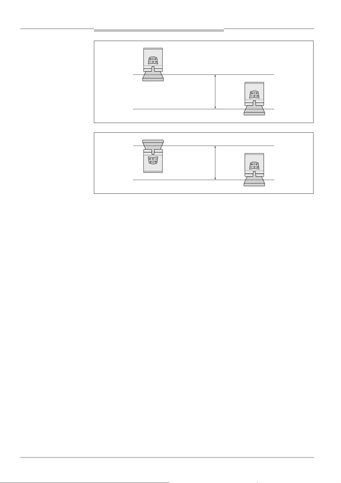
Chapter 4 Safety Laser Scanner
Fig.32:
Reverse mounting of
Fig.33:
Reverse mounting of
Min. 100
mm
Min. 100
mm
two S200, with parallel offset
one S200, with parallel offset
Mounting
S200
42 © SICK AG • Industrial Safety Systems • Germany • All rights reserved 8011692/02-06-06
Page 43

Safety Laser Scanner Chapter 5
Fig.34:
Screw terminal strip
S200
Electrical installation
5 Electrical installation
Switch the entire machine/system off line!
WARNING
The machine/system could inadvertently start up while you are connecting the devices.
To prevent an unintentional start, ensure that the entire machine/system is
isconnected during the electrical installation.
d
on the system plug
Notes
Route all cables and connection cables such that they are protected from damage.
Ensure that any control systems or other devices forming part of the safety installation
meet the stipulated category according to EN 954<1!
If you use screened cable, lay the screen evenly around the cable gland.
Ensure that the S200 is adequately protected electrically. You will find the electrical data
necessary for determining the correct fuse in section 11.4 “Data sheet” on page 65.
The electrical connections for the S200 are made at the system plug. A pre-assembled
connector variant and an un-assembled connector variant are available (see page 46).
5.1 System connection
You will find all inputs and outputs of the S200 on the 24-pin screw terminal connection +
FE in the system plug.
Notes
8011692/02-06-06 © SICK AG • Industrial Safety Systems • Germany • All rights reserved 43
If the cable gland/blanking plug is missing or not tightened, or if fixing screws are
missing or not tightened on the system plug, the IP 65 enclosure rating is not met.
All inputs and outputs on the S200 are to be used only in the context specified.
Page 44

Chapter 5 Safety Laser Scanner
Tab.7:
Terminal assignment
Electrical installation
S200
5.1.1 Pin assignment on the system plug
at the system plug
WARNING
Pin Signal Function
FE Functional earth
1 +24V DC Supply voltage S200
2 0V DC Supply voltage S200
3 OSSD1 Output signal switching device
4 OSSD2 Output signal switching device
5 RESET Input, reset
6 EDM Input, external device monitoring
13 ERR Application diagnostic output — error/contamination
14 WF Application diagnostic output, object in warning field
15 RES_REQ Application diagnostic output, reset required
16 STBY Control input for the activation of the stand-by mode
5.1.2 OSSDs
Only ever connect one downstream switching element to an OSSD!
Each output signal switching device (OSSD) is only allowed to be connected to one
switching element (e.g. relay or contactor). If several switching elements are required, you
must choose a suitable form of contact duplication.
5.1.3 Functional earth
To achieve the specified EMC safety, the functional earth FE must be connected (e.g. to
the central earth star point on the vehicle or the system).
44 © SICK AG • Industrial Safety Systems • Germany • All rights reserved 8011692/02-06-06
Page 45
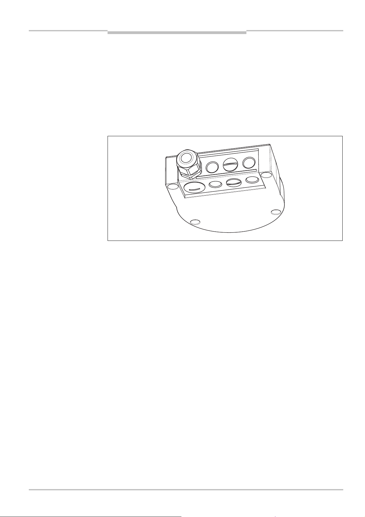
Safety Laser Scanner Chapter 5
Fig.35:
System plug SX0B-
S200
Electrical installation
5.2 System plug assembly
he system plug has holes for cable glands on the underside and on the rear.
T
system plug SX0B-A0000G
1 cable gland with M16 cable gland
1 cable gland without M16 cable gland (blanking plug)
2 cable glands without M12 cable gland (blanking plugs)
Note
A0000G
You can also procure the S200 with pre-assembled system plug with varying cable lengths
(see section 5.3 “Pre-assembled system plugs” on page 46 and section 12.3.2 “System
plug” on page 74).
Recommendation
If you do not want to assemble the system plug yourself, you will find suitable cables in the
ordering information (see section 12.3.4 “Self assembly connecting cables” on page 75).
8011692/02-06-06 © SICK AG • Industrial Safety Systems • Germany • All rights reserved 45
Page 46

Chapter 5 Safety Laser Scanner
Tab.8:
Pin assignment:
pre-
Electrical installation
S200
5.3 Pre-assembled system plugs
o connect the S200, the following pre-assembled system plugs are available (see also
T
section 12.3.2 “System plug” on page 74):
SX0B-B1105G
– with 11 cores, unscreened (M16 cable gland)
– 5 m long
SX0B-B1110G
– with 11 cores, unscreened (M16 cable gland)
– 10 m long
SX0B-B1120G
– with 11 cores, unscreened (M16 cable gland)
– 20 m long
assembled system plug
Pin Signal Wire colour
FE Functional earth Green
1 +24V DC Brown
20V DC Blue
3 OSSD1 Grey
4 OSSD2 Pink
5 RESET Red
6 EDM Yellow
13 ERR White/black
14 WF White/brown
15 RES_REQ Red/blue
16 STBY White/green
SX0B-B1105G
SX0B-B1110G
SX0B-B1120G
46 © SICK AG • Industrial Safety Systems • Germany • All rights reserved 8011692/02-06-06
Page 47
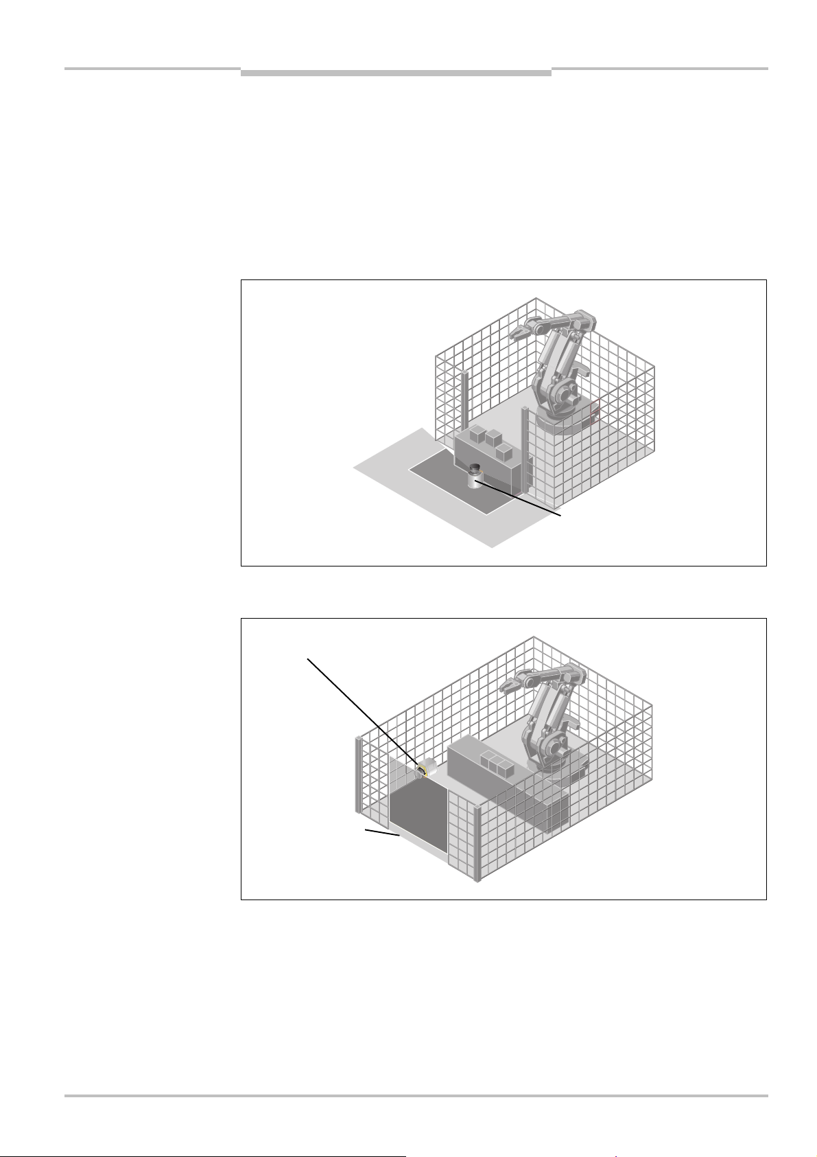
Application examples and
Fig.36:
Hazardous area
Fig.37:
Access protection
Protective field and warning field
Protective field – vertically
Floor as reference
Safety Laser Scanner Chapter 6
S200
connection diagrams
6 Application examples and connection diagrams
The examples shown are only provided as an aid for your planning. You may need to
consider additional protection measures for your application.
6.1 Stationary applications
6.1.1 Applications with one monitored area
protection
– horizontally mounted
The area is permanently monitored by the S200.
mounted
The access is monitored permanently. For safety against manipulation on the S200, e.g.
the floor is used as a reference. If the alignment of the S200 changes (e.g. due to changes
to the bracket), the S200 switches its OSSDs to the OFF state.
8011692/02-06-06 © SICK AG • Industrial Safety Systems • Germany • All rights reserved 47
Page 48
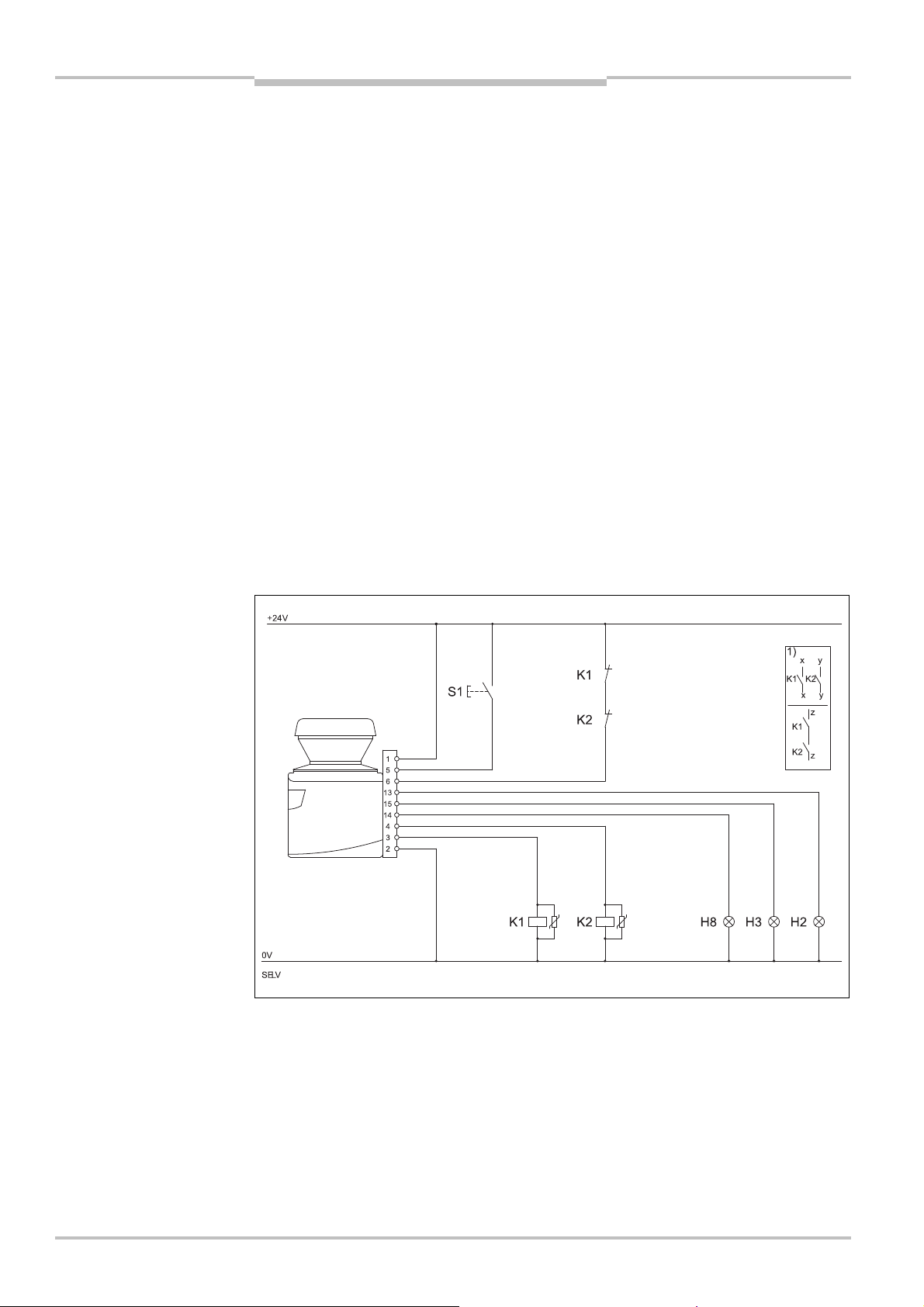
Application examples and
Fig.38:
Connection diagrams
S200
Chapter 6 Safety Laser Scanner
Notes
connection diagrams
6.2 Connection diagrams
Only use relays/contacts with positively guided contacts. The protection elements
connected in parallel with the relays/contactors are used for arc-suppression.
Ensure that there is adequate arc-suppression at the relays/contactors. Take into
account that arc-suppressors may lengthen the response time.
The arc-supressors must be in parallel with the relays/contactors (not across the
contacts).
Sketch key
1) = output circuits
These contacts are to be connected to the controller such that, with the output circuit
open, the dangerous state is disabled. Observe the maximum values for the loading of
the outputs (see section 11.4 “Data sheet” on page 65).
2) = functional earth (FE)
To achieve the specified EMC safety, the functional earth (FE) must be connected (e.g. to
the central earth star point on the vehicle or the system).
H2 = sensor for error/contamination
H3 = sensor for Reset required
H8 = sensor for warning field interruption
S200
for restart interlock and
external device monitoring
6.2.1 Restart interlock and external device monitoring
2)
S200 in conjunction with relays/contactors; operating mode: with restart interlock and
external device monitoring.
48 © SICK AG • Industrial Safety Systems • Germany • All rights reserved 8011692/02-06-06
Page 49

Safety Laser Scanner Chapter 7
Fig.39:
Configuration
Configuration connection
S200
Configuration
7 Configuration
7.1 Default delivery status
The S200 is delivered in a non-configured default status.
The operational status is Waiting for configuration.
The output signal switching devices (OSSDs) are in the OFF state,
the red LED illuminates: .
The 7<segment display indicates .
7.2 Preparation of the configuration
How to prepare the configuration:
Make sure that the safety laser scanner has been correctly mounted and that the
electrical connections are correct and in place.
Have the necessary tools at hand.
To configure the safety laser scanner you need:
CDS (Configuration & Diagnostic Software) on CD<ROM, version 3.3 or higher
user manual for CDS on CD<ROM
PC/notebook with Windows 98/NT 4/2000 Professional/ME/XP and a serial RS<232
interface (PC/Notebook not included)
service cable between PC and S200 (not in the delivery)
connection
Notes
How to configure the S200 with the aid of the CDS:
For configuration and diagnostics using the CDS, connect the PC to the configuration
connection.
Two service cables of different length are available for the connection of the PC/notebook
to the S200 (see 12.3 on page 74).
Ensure that the service cable is not laid in close proximity to high power electrical drives
or cables carrying high power. In this way you will avoid EMC effects on the service cable.
The service cable is only allowed to be connected for configuration and diagnostics. The
service cable must be disconnected and the protective cap fitted in operation.
To configure the device, please read the user manual for the CDS (Configuration &
Diagnostic Software) and use the online help function of the programme.
8011692/02-06-06 © SICK AG • Industrial Safety Systems • Germany • All rights reserved 49
Page 50

Chapter 8 Safety Laser Scanner
Tab.9:
7$segment display
Commissioning
S200
8 Commissioning
8.1 Initial commissioning
Commissioning requires a thorough check by qualified personnel!
WARNING
Before you operate a system protected by the S200 safety laser scanner for the first time,
make sure that the system is first checked and released by qualified personnel. The result
of the test must be documented. Please read the notes in chapter 2 “On safety” on
page 8.
Prior to releasing the machine, check whether the access to the hazardous area or the
hazardous point is completely monitored by the protective devices. Following approval of
the machine also check at regular intervals (e.g. in the morning at the start of work)
whether the S200 correctly switches the OSSDs to the OFF state as soon as there is an
object in the protective field. This test should be performed along all protective field
boundaries as per the specific regulations for the application (see section 8.3 “Test
notes” on page 52).
during and after the power
up sequence on initial
commissioning
8.1.1 Power up sequence
After power up the S200 runs through a power up cycle. During the power up cycle, the
7<segment display indicates the device status.
During the initial commissioning of an S200 the following indications are possible:
Step Display Meaning
1 , , , ,
, , ,
2 Power up cycle, during initial
Other display Safety lock activated. Malfunction in
Power-up cycle, testing the 7<segment
display. All segments are activated
sequentially.
commissioning:
device in configuration mode
external conditions or in the device
itself. See section 10.4 “Error and
status indications on the 7<segment
display” on page 58.
50 © SICK AG • Industrial Safety Systems • Germany • All rights reserved 8011692/02-06-06
Page 51

Safety Laser Scanner Chapter 8
Tab.10:
LED indication
after
Tab.11:
7$segment displ
ay
S200
Commissioning
the power up sequence
Note
Step Display Meaning
1
2
3
The duration of power up depends on the volume of the configuration data and can take
up to 25 seconds.
Other display Safety lock activated. Malfunction (see
Device self-test
Device self-test
Device status waiting for configuration
or object in the protective field, OSSDs
in the OFF state
section 10.3 “Error and status
indications on the LEDs” on page 56)
8.2 Re-commissioning
Commissioning requires a thorough check by qualified personnel!
Before you re-commission a system protected by the S200 safety laser scanner for the
first time, make sure that the system is first checked and released by qualified personnel.
The result of the test must be documented. Please read the notes in chapter 2 “On safety”
on page 8.
Prior to releasing the machine, check whether the access to the hazardous area or the
hazardous point is completely monitored by the protective devices. Following approval of
the machine also check at regular intervals (e.g. in the morning at the start of work)
whether the S200 correctly switches the OSSDs to the OFF state as soon as there is an
object in the protective field. This test should be performed along all protective field
boundaries as per the specific regulations for the application (see section 8.3 “Test
notes” on page 52).
during and after the power
up sequence on recommissioning
8.2.1 Power up sequence
After power up the S200 runs through a power up cycle. During the power up cycle, the
7<segment display indicates the device status.
During the re-commissioning of an S200 the following indications are possible:
Step Display Meaning
1 , , ,,
, , ,
2 No display
or
Other display Safety lock activated. Malfunction (see section 10.3 “Error
Power up cycle, testing the 7<segment display. All segments
are activated sequentially.
Device ready for operation
or
Device ready for operation but object in the protective field
and status indications on the LEDs” on page 56).
8011692/02-06-06 © SICK AG • Industrial Safety Systems • Germany • All rights reserved 51
Page 52

Chapter 8 Safety Laser Scanner
Tab.12:
LED indication after
Commissioning
S200
the power up sequence
Display Meaning
Other display Safety lock activated. Malfunction (see section 10.3 “Error
Power up cycle, step 1
Power up cycle, step 2
The device is operational, object in protective field and
warning field.
Or: The device is operational, object in warning field.
r: The device is operational, no object in protective field
O
and warning field.
Or: The device is operational, no object in protective field
and warning field. Reset required
and status indications on the LEDs” on page 56)
8.3 Test notes
8.3.1 Pre-commissioning tests
The purpose of the pre-commissioning tests is to confirm the safety requirements
specified in the national/international rules and regulations (EC Conformity). This applies
particularly to the safety requirements in the machine directive or work equipment
directive.
WARNING
Note
Ensure that you do not place anybody at risk during initial commissioning of the
machine!
Always expect that the machine, plant or the protective device does not yet behave as you
have planned.
Ensure that there are no persons in the hazardous area during initial commissioning.
Check the effectiveness of the protective device mounted to the machine, using all
selectable operating modes as specified in the checklist in the annex (see section 13.2
“Manufacturer’s checklist” on page 77).
Make sure that the operating personnel of the machine protected by the safety laser
scanner are properly instructed by specialist personnel before being allowed to operate
the machine. Instructing the operating personnel is the responsibility of the machine
owner.
Ensure that the information label Important information, which is included with the
laser scanner on delivery, is affixed to the machine in a place where it is clearly visible
for the operators. Ensure that the operators have the possibility to perform this daily
check correctly.
The annex to this document includes a checklist for review by the manufacturer and
OEM. Use this checklist as a reference before commissioning the system for the first
time (see section 13.2 “Manufacturer’s checklist” on page 77).
Document the adjustment of the scanner and the results of the testing during initial
commissioning in a traceable manner. For this purpose also print out the complete
configuration of the scanner (including protective field shapes) and include these with
the documentation.
Your SICK subsidiary will be pleased to provide you with advice on initial commissioning.
52 © SICK AG • Industrial Safety Systems • Germany • All rights reserved 8011692/02-06-06
Page 53

Safety Laser Scanner Chapter 8
S200
WARNING
Commissioning
8.3.2 Regular inspection of the protective device by qualified personnel
Check the system following the inspection intervals specified in the national rules and
regulations. This procedure ensures that any changes on the machine or manipulations
of the protective device after the first commissioning are detected.
If major changes have been made to the machine or the protective device, or if the
safety laser scanner has been modified or repaired, check the plant again as per the
checklist in the annex (see section 13.2 “Manufacturer’s checklist” on page 77).
8.3.3 Daily testing of the protective device by a specialist or authorised personnel
The effectiveness of the protective device must be checked daily by a specialist or by
authorised personnel. The test must also be performed if the operating mode is changed.
No further operation if errors occur during the test!
If any one of the following points is not met, it is not permitted to continue to work on the
machine or operate the vehicle. In this case the installation of the S200 must be checked
by specialised personnel (see section 8.3.2 “Regular inspection of the protective device by
qualified personnel” on page 53).
Check the mechanical installation to ensure that all mounting screws are secure and
that the is properly aligned S200.
Check each S200 device for visible changes such as damage, manipulation etc.
Switch on the machine/plant.
Watch the LEDs on each S200.
If not at least one LED of each S200 is permanently lit when the machine/plant is
switched on, it is to be assumed that there is a fault in the machine or plant. In this case
the machine must be shut down immediately and checked by a specialist.
Deliberately obstruct the protective field without risk to any personnel while the machine
is running in order to test the effectiveness of the entire system. The LEDs of the S200
device must change from green to red and the dangerous movement must stop
immediately.
Repeat this test at different points in the danger area and on all S200 devices . If you
discover any non-conformance of this function, the machine/plant must be shut down
immediately and checked by a specialist.
For stationary applications, check that the danger area marked out on the floor matches
the shape of the protective field stored in the S200 and that any gaps are protected by
additional safety measures. In the case of mobile applications, check that the moving
vehicle actually stops in a timely manner at the protective field boundaries which are set
in the S200 and listed on the information label on the vehicle or in the configuration
protocol. If you discover any non-conformance of this function, the
machine/plant/vehicle must be stopped immediately and checked by a specialist.
8011692/02-06-06 © SICK AG • Industrial Safety Systems • Germany • All rights reserved 53
Page 54

Chapter 9 Safety Laser Scanner
Care and maintenance
S200
9 Care and maintenance
Do not make any repairs to the device!
WARNING
Note
The S200 does not contain any repairable components. For this reason do not open the
200 components and only replace the parts that are described in the following chapters
S
as replaceable.
Switch the entire machine/system off line!
The system could inadvertently start up while you are replacing the optics cover. As a
matter of principle, always isolate the machine from the power supply during all work on
the machine and safety laser scanner.
9.1 Cleaning optics cover
The S200 safety laser scanner is largely maintenance-free. The optics cover on the safety
laser scanner should however be cleaned regularly and if it is contaminated.
Do not use aggressive detergents.
Do not use abrasive cleaning agents.
Static charges cause dust particles to be attracted to the optics cover. You can diminish
this effect by using the anti-static plastic cleaner (SICK Part No. 5600006) and the SICK
lens cloth (Part No 4003353) (see section 12.3 “Accessories/spare parts” on page 74).
WARNING
Notes
How to clean the optics cover:
Use a clean and soft brush to remove dust from the optics cover.
Now wipe the window for light output on the optics cover with a clean and damp cloth.
9.2 Replacing optics cover
Perform an optics cover calibration with the aid of the CDS after the replacement of the
optics cover!
The level of contamination is measured continuously during the operation of the S200. For
this purpose the optics cover calibration must first be performed; this then serves as a
reference for the contamination measurement (status = not contaminated).
The optics cover calibration is only allowed to be performed with a new optics cover! The
new optics cover must be free of contamination at the time of the optics cover calibration.
The optics cover calibration should be performed at room temperature (10<30 °C)!
If the optics cover is scratched or damaged, you must replace the optics cover. Order the
replacement optics cover from SICK (see section 12.3 “Accessories/spare parts” on
page 74).
The optics cover on the S200 is an optical part that must not be soiled or scratched on
replacement.
The optics cover is only allowed to be replaced by specialist personnel in a dust and dirt-
free environment.
Never replace the optics cover during ongoing operation, as internal parts may be
irreparably damaged in certain circumstances and dust particles may enter the device.
It is imperative that you avoid contamination of the inside, e.g. with fingerprints.
54 © SICK AG • Industrial Safety Systems • Germany • All rights reserved 8011692/02-06-06
Page 55

Safety Laser Scanner Chapter 9
Fig.40:
Undo the fixing
S200
Notes
screws for the front screen
Care and maintenance
Do not use any additional sealant for sealing the optics cover, e.g. silicon, as these
ubstances may affect the optics.
s
Mount the optics cover as per the following instructions to ensure that the housing is
sealed to IP 65.
This is how you replace the optics cover:
Only use a new optics cover (see 12.3.8 on page 75).
When replacing the optics cover, take ESD protection measures.
Set a torque wrench to 1.2 Nm (hand-tight) and have this at hand.
Disconnect the system plug and remove the S200.
Take the S200 to a clean place (office, repair shop or similar).
First clean the outside of the S200. This prevents foreign bodies entering the device
when it is opened.
Undo the fixing screws to for the optics cover.
Then remove the optics cover.
Check whether the mirror on the motor is clean and remove any contamination with an
optic brush.
Take the new optics cover out of the packaging and remove the protection for the seal.
Remove any remnants of packaging.
Place the optics cover on the laser scanner and fit the new fixing screws to .
When fitting the new cover, ensure the arrow on the top of the cover points to the front
and that the optics cover is fully in contact without a gap.
Then tighten the front screws with the torque set.
Make sure the optics cover is free of dirt and that it is not damaged.
8011692/02-06-06 © SICK AG • Industrial Safety Systems • Germany • All rights reserved 55
Re-commissioning the S200:
Correctly re-mount the S200 (see chapter 4 “Mounting” on page 27).
Connect the S200 system plug.
Then perform an optics cover calibration with the aid of the CDS.
Page 56

Chapter 10 Safety Laser Scanner
Tab.13:
Status indicat
ors
Diagnostics
S200
10 Diagnostics
This chapter describes how to identify and remedy errors and malfunctions during the
operation of the safety laser scanner.
10.1 In the event of faults or errors
Do not operate if behaviour is unclear!
WARNING
Stop the machine, the system or the vehicle if you cannot clearly identify or allocate an
error and if you cannot safely remedy the malfunction.
10.2 SICK support
If you cannot remedy an error with the help of the information provided in this chapter,
please contact your local SICK representative.
Make a note of the telephone number of your SICK subsidiary so that you or other users
have this number easily at hand. You will find the telephone number on the rear of these
operating instructions.
during operation
Telephone number of your SICK subsidiary
10.3 Error and status indications on the LEDs
This section describes the meaning of the indications and LED error messages and how
you can respond. You will find a description of the indicators in section 3.6 “Indicators and
outputs” on page 26, the connections for the outputs in section 5.1 “System connection”
on page 43.
Display Output level Possible cause
At the OSSDs Object in the protective field, OSSDs in the OFF
state
At the OSSDs Protective field unoccupied, OSSDs in ON
state
At the warning field
output
Object in warning field
56 © SICK AG • Industrial Safety Systems • Germany • All rights reserved 8011692/02-06-06
Page 57

Safety Laser Scanner Chapter 10
Tab.14:
LED error messages
S200
Diagnostics
Display Output level Possible cause Remedying the error
At the OSSDs
On the application
diagnostic output
At the Res_Req output
1 Hz
On the
error/contamination
output
On the application
diagnostic output
On the application
diagnostic output
1 Hz
On the application
diagnostic output
4 Hz
No operating voltage,
or voltage too low
eset required Operate the control
R
Optics cover
contaminated, no
operation
Optics cover
contaminated, still in
operation
System error Pay attention to the
Check the voltage
supply and activate,
if necessary.
switch for restarting
or resetting.
No error
Clean the optics
cover.
Clean the optics
cover.
error display of the
7<segment display or
carry out a
diagnostics with the
aid of the CDS.
If necessary, switch
the device off and
back on again.
8011692/02-06-06 © SICK AG • Industrial Safety Systems • Germany • All rights reserved 57
Page 58

Chapter 10 Safety Laser Scanner
Tab.15:
Error and status
Diagnostics
S200
10.4 Error and status indications on the 7Csegment display
The lock-out operational status
In case of certain faults or an erroneous configuration, the system can go into the lock<out
status. The 7<segment display on the safety laser scanner then indicates , , , , ,
, , , , , , or . To place the device back in operation, proceed as follows:
Rectify the cause of the fault as per Tab. 15.
Switch the power supply for the S200 off and back on again.
Or
Restart the laser scanner with the aid of the CDS.
This section explains the meaning of the error displays on the 7<segment display and how
to respond to the messages. You will find a description of the positions and symbols on the
S200 in section 3.6 “Indicators and outputs” on page 26.
indications on the 7$segment
display
Display Possible cause Remedying the error
, , ,,
, , ,
Object in protective
Initialising the device The display goes out automatically when the
Waiting for
or
Error in control switch
S200 faulty Send the S200 to the manufacturer for
Power-up cycle — all
segments are
activated sequentially.
field
configuration or
configuration not
completed
EDM error Check whether the contactors are working
for restarting or
resetting
No error
No error
S200 has been initialised.
If the display does not go off:
Check the system configuration with the aid
of the CDS. Transfer the corrected
configuration to the S200 again.
No error
Prepare a configuration with the aid of the
CDS (Configuration & Diagnostic Software)
or transfer an existing configuration to the
S200.
correctly or if they are wired incorrectly and
rectify any error.
If is displayed: Switch the device off and
back on again.
Check the functionality of the control switch.
The button may be defective or operated.
Check the wiring of the control switch for
short-circuit to 24 V.
repair.
58 © SICK AG • Industrial Safety Systems • Germany • All rights reserved 8011692/02-06-06
Overcurrent on OSSD
connection 1
Short-circuit to 24 V at
OSSD connection 1
Check the switching element connected
(contactor, relay). Replace, if necessary.
Check the wiring for short-circuit to 0 V.
Check the wiring for short-circuit to 24 V.
Page 59

Safety Laser Scanner Chapter 10
S200
Diagnostics
Display Possible cause Remedying the error
Short-circuit to 0 V at
OSSD connection 1
Overcurrent on OSSD
connection 2
Short-circuit to 24 V at
SSD connection 2
O
Short-circuit to 0 V at
OSSD connection 2
Short-circuit between
OSSD connection 1
and 2
General OSSD wiring
error
Maximum measuring
range exceeded
Check the wiring for short-circuit to 0 V.
Check the switching element connected
(contactor, relay). Replace, if necessary.
Check the wiring for short-circuit to 0 V.
Check the wiring for short-circuit to 24 V.
Check the wiring for short-circuit to 0 V.
Check the wiring and rectify the error.
Check the complete wiring of the OSSDs.
For the correct function of the safety laser
scanner, always ensure that measured
values are received within a sector of 90°.
In this sector the laser scanner must detect,
e.g., building walls within its maximum
measuring range of 30 m.
Device is dazzled Check whether the S200 is being dazzled by
an external light source, e.g. headlight,
infrared light sources, stroboscopic light,
sun etc.
If necessary, re-mount the device.
Temperature error. The
operating temperature
of the S200 has
exceeded the
permissible range.
Invalid configuration of
the EDM
There is a short-circuit
between the input for
the control switch for
restarting or resetting
and another input or
output.
Check whether the S200 is operated as per
the permissible ambient conditions.
Verify that the EDM on the machine
controller is connected.
Check the cabling for cross-circuits.
8011692/02-06-06 © SICK AG • Industrial Safety Systems • Germany • All rights reserved 59
Page 60

Chapter 10 Safety Laser Scanner
Diagnostics
S200
Display Possible cause Remedying the error
Note
Stand-by mode,
the OSSDs are in the
OFF state, the laser is
switched off.
Dazzling of the
If you have problems during troubleshooting, contact SICK support. Keep a copy of the
print out of the results of the diagnostics at hand.
indow for light output
W
on the optics cover
contaminated
contamination
measurement (there
may not be an optics
cover fitted)
No error. If the criteria for the stand-by mode
are withdrawn, readiness for operation is re-
established.
If the display does not go off:
Check the level on the STBY input.
Clean the window for the light output on the
optics cover.
Check whether the S200 is being dazzled by
an external light source, e.g. headlight,
infrared light source, stroboscopic light, sun
etc.
or
Fit the new optics cover (then perform optics
cover calibration).
10.5 Extended diagnostics
The CDS software supplied with the device (Configuration & Diagnostic Software) includes
extended diagnostic options. It allows you to narrow down the problem if the error is non-
specific or if you experience usage downtime problems. Detailed information to be found …
in the online help for the CDS (Configuration & Diagnostic Software).
in the user manual for the CDS.
60 © SICK AG • Industrial Safety Systems • Germany • All rights reserved 8011692/02-06-06
Page 61
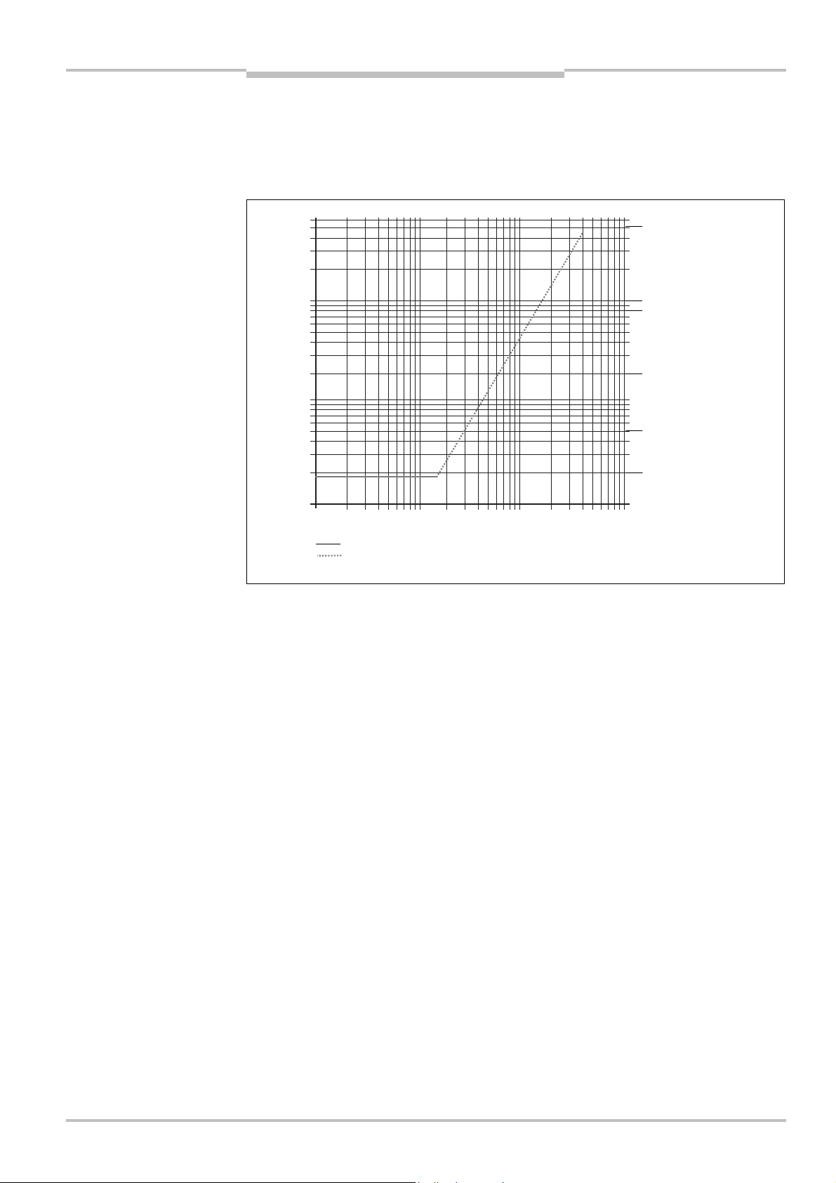
Safety Laser Scanner Chapter 11
Fig.41:
Diagram of scanning
Reflectivity [%]
Scanning range [m]
Black shoe leather
0.112100.2
0.5125102050520
50
100
200
500
Mat black paint
White plaster
Writing paper
Reflectors
>
2000
%
Protective field
Warning field
S200
Technical specifications
11 Technical specifications
11.1 Characteristics
ranges for various
reflectances
Reflective films > 300%
Grey
cardboard
11.2 OSSD response times
The total response time of your application is dependent on …
the basic response time of the S200.
the multiple sampling set.
the OSSDs used.
How to calculate the total response time T
T
=tB+ T
S
MFA
:
S
Where …
t
= Basic response time = 80 ms
B
T
= Supplement due to multiple sampling > 2
MFA
8011692/02-06-06 © SICK AG • Industrial Safety Systems • Germany • All rights reserved 61
Page 62

Chapter 11 Safety Laser Scanner
Tab.16:
Supplements for
Technical specifications
S200
Multiple sampling
On the S200 at least double multiple sampling is always set. For a multiple sampling of 3
r higher you must add a supplement of 80 ms to the basic response time.
o
multiple sampling
Multiple sampling Supplement Basic response time + supplement
2 times (basic setting) 0 ms 80 ms
3 times 40 ms 120 ms
4 times 80 ms 160 ms
5 times 120 ms 200 ms
6 times 160 ms 240 ms
7 times 200 ms 280 ms
8 times 240 ms 320 ms
9 times 280 ms 360 ms
10 times 320 ms 400 ms
11 times 360 ms 440 ms
12 times 400 ms 480 ms
13 times 440 ms 520 ms
14 times 480 ms 560 ms
15 times 520 ms 600 ms
16 times 560 ms 640 ms
62 © SICK AG • Industrial Safety Systems • Germany • All rights reserved 8011692/02-06-06
Page 63
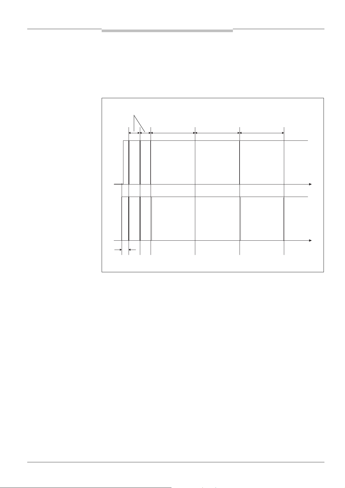
Safety Laser Scanner Chapter 11
Fig.42:
Diagram of the test
40 ms
120ms120ms120msApprox.
OSSD1
OSSD2
t
t
S200
Technical specifications
11.3 Timing behaviour of the OSSDs
he S200 tests the OSSDs immediately after switch on and then at regular intervals. For
T
this purpose the S200 briefly switches off both OSSDs (for 300 µs) and checks whether
the OSSDs switch to the OFF state during this time.
Note
pulses at the OSSDs
Ensure that the safety inputs on the controller used do not respond to these test pulses
and as a result cause the machine or system to unintentionally shutdown!
35 ms
Approx. 35 ms after the switch on of the OSSDs, the S200 performs the first voltage test
and then after a half basic response time (40 ms) performs a second voltage test .
After a further half basic response time of the S200 there is a shut-down test , 120 ms
later a further voltage test . Then the S200 performs a shut-down test and a voltage test
alternately at an interval of 120 ms. Fig. 43, Fig. 44 and Fig. 45 show the pulse durations
for the individual tests.
8011692/02-06-06 © SICK AG • Industrial Safety Systems • Germany • All rights reserved 63
Page 64

Chapter 11 Safety Laser Scanner
Fig.43:Voltage test after
Fig.44:
Shut-down test
Fig.45:
Voltage test
600µs300µs300
µs
OSSD1
OSSD2
600µs300µs300µsOSSD1
OSSD2
300µsOSSD1
OSSD2
switching on the OSSDs
Technical specifications
S200
64 © SICK AG • Industrial Safety Systems • Germany • All rights reserved 8011692/02-06-06
Page 65

Safety Laser Scanner Chapter 11
Tab.17:
Data sheet
S200
S200
Technical specifications
11.4 Data sheet
Minimum Typical Maximum
General data
Laser protection class Laser class 1 (IEC 60825<1:2001.
Complies with 21 CFR 1040.10 and
1040.11)
Enclosure rating IP 65 (EN 60529)
Protection class according to DIN VDE 0106,
DIN EN 50178
Type according to IEC 61496<12
Functional safety of electrical, electronic and
programmable electronic safety-related
systems (IEC/EN 61508)
Operating temperature range –10 °C +50 °C
Storage temperature range –25 °C +70 °C
Humidity (taking into account the operating
temperature range)
Vibration IEC/EN 61496<1, section 5.1.2 and
Frequency range 10 Hz 150 Hz
Amplitude 0.35 mm or 5 g
Shock resistance According to IEC/EN 61496<1,
Single shock 15 g, 11 ms
Continuous shock 10 g, 16 ms
Sender Pulsed laser diode
Wavelength 895 nm 905 nm 915 nm
Divergence of the collimated beam (solid
angle)
Pulse duration 4.5 ns
Average output power 1.5 µW
Light spot size at optics cover 8 mm
Size of light spot at 1.5 m scanning range 28 mm
II
SIL1
max. 24 h
IEC/EN 61496<1, section 5.1.2 and
5.4.2, as well as
IEC 61496<3, section 5.4.2
5.4.4.1, as well as IEC 61496<3,
section 5.4.4.1
section 5.1 and 5.4.4.2, as well as
IEC 61496<3, section 5.4.4.2
14 mrad
8011692/02-06-06 © SICK AG • Industrial Safety Systems • Germany • All rights reserved 65
Page 66

Chapter 11 Safety Laser Scanner
Technical specifications
S200
Minimum Typical Maximum
Housing
Material Aluminium die-cast
Colour RAL 1021 (rape yellow)
Optics cover
Material Polycarbonate
Surface finish Outside with scratch-resistant coating
System plug ESD protected
Material Aluminium die-cast
Colour RAL 9005 (black)
Dimensions S200
2)
Height 152 mm
Width 102 mm
Depth 105 mm
Total weight (without connecting cables) 1.2 kg
Functional data
Resolution 30, 40, 50, 70 mm
Protective field of the S200
At 30 mm resolution 1.25 m
At 40, 50, 70 mm resolution 1.50 m
Scan angle 270°
Reflectivity 1.8% Several
1000%
(reflec-
3)
)
tors
Angular resolution 0.5°
Protective field supplement generally
100 mm
necessary
Supplement for retroreflectors in scan plane
200 mm
at a distance of less than 1 m to the protective
field boundary
Evenness of the scan field at 1.5 m ±50 mm
Distance from mirror axis of rotation (zero
55 mm
point on the X< and Y axis) to the rear of the
device
Distance between centre of the scan plane
116 mm
and the bottom edge of the housing
Warning field
4)
8 m
Distance measuring range 30 m
2)
Without fixing screws and projection of cable glands with system plug mounted.
3)
Complies with Diamond Grade 3000X™ (approx. 1250 cd/lx × m²).
4)
The detection capability of the warning field is dependent on the remission of the objects to be detected (see
section 11.1 on page 61).
66 © SICK AG • Industrial Safety Systems • Germany • All rights reserved 8011692/02-06-06
Page 67

Safety Laser Scanner Chapter 11
S200
Technical specifications
Minimum Typical Maximum
Number of multiple samplings
216
(configurable via CDS)
Power-up delay
Of a configured device 15 s 25 s
Restart after (configurable) 2 s 60 s
Electrical data
Supply voltage (SELV)
Permissible residual ripple
Switch on current
5)
6)
)
7
16.8 V 24 V 30 V
±5 %
2 A
Operating current at 24 V without output load 0.25 A 0.33 A
Operating current with max. output load 1.65 A
Power consumption without output load 6 W8 W
Power consumption with maximum output
40 W
load
Electrical connection System plug with screw terminal
connections
Technical specifications, screw type
terminal FE
Cross-section of rigid cores 0.3 mm² 1.6 mm²
Cross-section of flexible cores
8)
0.3 mm² 1.6 mm²
American Wire Gauge (AWG) 22 14
Insulation stripping length for the cores 5 mm
Screw tightening torque 0.5 Nm
Technical specifications, screw terminals
Cross-section of rigid cores 0.14 mm² 1.5 mm²
Cross-section of flexible cores
9)
0.14 mm² 1.0 mm²
American Wire Gauge (AWG) 26 16
Insulation stripping length for the cores 5 mm
Screw tightening torque 0.22 Nm 0.3 Nm
Cable length for power supply tolerance ±10%
For wire cross-section 1 mm² 50 m
For wire cross-section 0.5 mm² 25 m
For wire cross-section 0.25 mm² 12 m
5)
The voltage supply must be capable of buffering brief mains voltage failures of 20 ms as specified in
EN 60204. Suitable power supplies are available as accessories from SICK (Siemens series 6 EP 1 — as per
DIN 40839<1, test pulse 5 (Load Dump) limited to 58 V, tested!)
6)
The absolute voltage level must not drop below the specified minimum voltage.
7)
The load currents for the input capacitors are not taken into account.
8)
Core terminating sleeves are not required.
9)
Core terminating sleeves are not required.
8011692/02-06-06 © SICK AG • Industrial Safety Systems • Germany • All rights reserved 67
Page 68

Chapter 11 Safety Laser Scanner
Technical specifications
S200
Minimum Typical Maximum
Cable length for power supply tolerance ±5%
For wire cross-section 1 mm² 60 m
For wire cross-section 0.5 mm² 30 m
For wire cross-section 0.25 mm² 15 m
Cable length for power supply tolerance ±1%
For wire cross-section 1 mm² 70 m
For wire cross-section 0.5 mm² 35 m
For wire cross-section 0.25 mm² 17 m
Input for control switch for restarting or
resetting
Input resistance when HIGH 2 k
Voltage for HIGH 11 V 24 V 30 V
Voltage for LOW –3 V 0 V 5 V
Input capacitance 15 nF
Static input current 6 mA 15 mA
Input EDM
Input resistance when HIGH 2 k
Voltage for HIGH 11 V 24 V 30 V
Voltage for LOW –3 V 0 V 5 V
Input capacitance 15 nF
Static input current 6 mA 15 mA
Stand-by mode input
Input resistance when HIGH 2 k
Voltage for HIGH 11 V 24 V 30 V
Voltage for LOW –3 V 0 V 5 V
Input capacitance 15 nF
Static input current 6 mA 15 mA
68 © SICK AG • Industrial Safety Systems • Germany • All rights reserved 8011692/02-06-06
Page 69

Safety Laser Scanner Chapter 11
Technical specifications
S200
Minimum Typical Maximum
OSSDs
Output signal switching device pair 2 PNP semiconductors, short-circuit
0)
1
protected
, cross-circuit monitored
HIGH switching voltage at 250 mA UV– 2.7 V U
V
Switching voltage LOW 0 V 0 V 3.5 V
1)
Source switching current
2)
Leakage current
1
1
6 mA 0.25 A
250 µA
Load inductance 2.2 H
Load capacity 2.2 µF at
50
Switching sequence (without switching) 5 1/
Permissible cable resistance
Test pulse width
14)
13)
2.5
230 µs 300 µs
Test frequency 120 ms
Switching time of the OSSDs from red to
120 ms
green
Time offset on switching the OSSDs between
2 ms
OSSD2 and OSSD1
Application diagnostics outputs warning field,
contamination of the optics cover/error, reset
required
HIGH switching voltage at 200 mA UV– 3.3 V U
V
Source switching current 100 mA 200 mA
Current limiting (after 5 ms at 25° C) 600 mA 920 mA
Power up delay 1.4 ms 2 ms
Switch off delay 0.7 ms 2 ms
s
10)
Applies to the voltage range between Vsand 0 V.
11)
Switching currents up to 500 mA are allowed briefly (100 ms).
12)
In the case of a fault (0-V cable open circuit) maximally the leakage current flows in the OSSD cable. The
downstream controller must detect this status as LOW. A FPLC (fail-safe programmable logic controller) must
be able to identify this status.
13)
Make sure to limit the individual line core resistance to the downstream controller to this value to ensure that
a cross-circuit between the outputs is safely detected. (Also note EN 60204<1.)
14)
When active, the outputs are tested cyclically (brief LOW). When selecting the downstream controllers, make
sure that the test pulses do not result in deactivation.
8011692/02-06-06 © SICK AG • Industrial Safety Systems • Germany • All rights reserved 69
Page 70

Chapter 11 Safety Laser Scanner
Technical specifications
S200
Minimum Typical Maximum
Configuration and diagnostics interface
Communication protocol RS<232 (proprietary)
Transmission speed 38400 Baud
Cable length at 38400 Baud and 0.25-mm²
cables
Galvanic de-coupling No
Output TxD HIGH 5 V15 V
Output TxD LOW –15 V –5 V
Voltage range RxD –15 V 15 V
Switching threshold RxD LOW –15 V 0.4 V
Switching threshold RxD HIGH 2.4 V 15 V
Short-circuit current at TxD –60 mA 60 mA
Max. voltage level at RxD –15 V 15 V
Max. voltage level at TxD –11 V 11 V
15 m
70 © SICK AG • Industrial Safety Systems • Germany • All rights reserved 8011692/02-06-06
Page 71
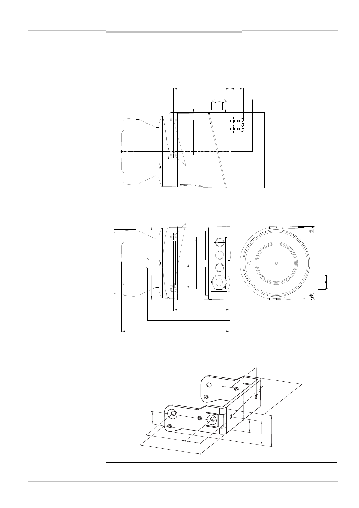
Safety Laser Scanner Chapter 11
Fig.46:
S200
dimensional
Fig.47:
Dimensional drawing,
16
21.9
15.9
24
10.5
5
94
M5 × 7.5
Technical specifications
S200
11.5 Dimensional drawings
11.5.1 S200
drawing (mm)
79.3
49
±0.2
M5 × 7.5
102
73
25
54.5
106
mounting kit 1a
11.5.2 Mounting kits
49
74.7
152
36.5
116
15.7
79.3
73
4
DIN74$F5
110.2
8011692/02-06-06 © SICK AG • Industrial Safety Systems • Germany • All rights reserved 71
Page 72

Chapter 11 Safety Laser Scanner
Fig.48:
Dimensional drawing,
Fig.49:
Dimensional drawing,
15.9
19.7
37.7
33.41818
19.7
Technical specifications
S200
mounting kit 1b
mounting kit 2
49
74.7
109.6
15.7
100
48
4
73
110.2
DIN74$F5
40.7
78.2
139.4
130
4
118.5
72 © SICK AG • Industrial Safety Systems • Germany • All rights reserved 8011692/02-06-06
Page 73

Safety Laser Scanner Chapter 11
Fig.50:
Dimensional drawing,
Fig.51:
Dimensional drawing
20.5
146
130
73
54.5
270°
Technical specifications
S200
mounting kit 3
158.8
150
of the scan plane with
mounting kit 1a (mm)
11.5.3 Scan plane origin
130
5
41
8011692/02-06-06 © SICK AG • Industrial Safety Systems • Germany • All rights reserved 73
23.8
116
36.4
74.7
69.7
59.7
126
106
Max. 200
Min. 15Min. 15
Page 74

Chapter 12 Safety Laser Scanner
Tab.18:
Part number of the
Tab.19:
Part numbers
Tab.20:
Part numbers
Ordering information
S200
12 Ordering information
12.1 Delivery S200
safety laser scanner
operating instructions and CDS (Configuration & Diagnostic Software) on CD-ROM
information label Important information
Note
System plugs not included.
System plugs without cable and pre-assembled system plugs are available from SICK AG
(see section 12.3.2 “System plug” on page 74). For further information see section 5.2
“System plug assembly” on page 45 and section 5.3 “Pre-assembled system plugs” on
page 46.
12.2 Available systems
system
mounting kit
Device type Part Part number
S20B-1011BA S200 1026823
12.3 Accessories/spare parts
12.3.1 Mounting kits
Mounting kit Description Part number
1a Mounting bracket for direct mounting at the rear
on wall or machine.
1b Mounting bracket for direct mounting at the rear
on wall or machine, with protection for the optics
cover.
2 Mounting bracket only in conjunction with
mounting bracket 1a or 1b. Cross-wise
adjustment possible.
3 Mounting plate only in conjunction with mounting
bracket 2. Length-wise adjustment possible
12.3.2 System plug S200
2034324
2034325
2039302
2039303
system plugs S200
74 © SICK AG • Industrial Safety Systems • Germany • All rights reserved 8011692/02-06-06
System plug Features Description Part number
SX0B-A0000G Without cable 2032807
SX0B-B1105G Pre-assembled, 5 m long
SX0B-B1110G Pre-assembled, 10 m long
SX0B-B1120G
One M16 cable gland and
one M12 blanking plug,
on the rear
cable, 11 cores
cable, 11 cores
Pre-assembled, 20 m long
cable, 11 cores
2032859
2032860
2032861
Page 75

Safety Laser Scanner Chapter 12
Tab.21:
Part numbers
Tab.22:Part numbers
Tab.23:
Part numbers
Tab.24:
Part numbers safety
Tab.25:
Part numbers safety
Tab.26:
Part numbers
S200
Ordering information
12.3.3 Service cable
service cables
connecting cables
documentation
Part Description Part number
Service cable 2 m For connecting the configuration connection to
6021195
the serial interface on the PC
M8, 4 pin/D<Sub 9 pin (DIN 41642) approx. 2 m
Service cable 8 m For connecting the configuration connection to
2027649
the serial interface on the PC
M8, 4 pin/D<Sub 9 pin (DIN 41642) approx. 8 m
12.3.4 Self assembly connecting cables
Part Part number
15-core, cross-section 0.56 mm² ( AWG 20) in 100-m reel 6030795
12.3.5 On the documentation
Part Part number
CDS (Configuration & Diagnostic Software) for S200 on CD-ROM
2032314
including online documentation and operating instructions in all
available languages
12.3.6 Safety relays
relays
controllers
miscellaneous
Part Description Part number
UE10<3OS2 Safety relay UE10<3OS with two screw type
6024917
terminals
UE10<3OS3 Safety relay UE10<3OS with three plug-in
6024918
terminals
12.3.7 Safety controllers
Part Description Part number
UE440-A0410 Safety controller for multifunctional applications 1023859
UE470-A0410 Safety controller for press applications 1023862
12.3.8 Miscellaneous
Part Description Part number
Optics cover Spare parts set for optics cover with replacement
2039248
seal and screws
Plastic cleaner Plastic cleaner and care product, anti-static,
5600006
1 litre
Lens cloth Cloth for cleaning the optics cover 4003353
Power supply, 2.5 A Power supply, 24 V DC, 2.5 A 6010361
8011692/02-06-06 © SICK AG • Industrial Safety Systems • Germany • All rights reserved 75
Power supply, 4 A Power supply, 24 V DC, 4 A 6010362
Page 76
Chapter 13 Safety Laser Scanner
Annex
S200
13 Annex
13.1 Declaration of conformity
Note
76 © SICK AG • Industrial Safety Systems • Germany • All rights reserved 8011692/02-06-06
You can obtain the complete EC declaration of conformity via the SICK homepage on the
Internet at: www.sick.com
Page 77

Safety Laser Scanner Chapter 13
S200
Annex
13.2 Manufacturer’s checklist
Checklist for the manufacturer/installer for the installation of electro-sensitive protective equipment (ESPE)
Details about the points listed below must be present at least during initial commissioning — they are, however,
dependent on the respective application, the specifications of which are to be controlled by the manufacturer/installer.
his checklist should be retained and kept with the machine documentation to serve as reference during recurring
T
tests.
1. Have the safety rules and regulations been observed in compliance with the directives/standards
applicable to the machine?
2. Are the applied directives and standards listed in the declaration of conformity? Yes No
3. Does the protective device comply with the required control category? Yes No
4. Is the access to the hazardous area/hazardous point only possible through the protective field of
the ESPE?
5. Have measures been taken to prevent and monitor unauthorised presence in the hazardous area
when hazardous area/hazardous point protection (mechanical point-of-operation guarding), and
have these been secured against removal?
6. Are additional mechanical protective measures fitted and secured against manipulation which
prevent reaching under, over or around the ESPE?
7. Has the maximum stopping and/or stopping/run-down time of the machine been measured,
specified and documented (at the machine and/or in the machine documentation)?
8. Has the ESPE been mounted such that the required safety distance from the nearest hazardous
point has been achieved?
9. Are the ESPE devices correctly mounted and secured against manipulation after adjustment? Yes No
10. Are the required protective measures against electric shock in effect (protection class)? Yes No
11. Is the control switch for resetting the protective device (ESPE) or restarting the machine present
and correctly installed?
12. Are the outputs of the ESPE (OSSDs) integrated in compliance with the required control category
and does the integration comply with the circuit diagrams?
13. Has the protective function been checked in compliance with the test notes of this
documentation?
14. Are the given protective functions effective at every setting of the operating mode selector switch? Yes No
15. Are the switching elements activated by the ESPE, e.g. contactors, valves, monitored? Yes No
16. Is the ESPE effective over the entire period of the dangerous state? Yes No
17. Once initiated, will a dangerous state be stopped when switching the ESPE on or off and when
changing the operating mode, or when switching to another protective device?
18. Has the information label “Important Information” for the daily check been attached so that it is
easily visible for the operator?
This checklist does not replace the initial commissioning, nor the regular inspection by specialist personnel.
Yes No
Yes No
Yes No
Yes No
Yes No
Yes No
Yes No
Yes No
Yes No
Yes No
Yes No
8011692/02-06-06 © SICK AG • Industrial Safety Systems • Germany • All rights reserved 77
Page 78

Chapter 13 Safety Laser Scanner
Annex
S200
13.3 Glossary
ctive opto-electronic protective device responsive to diffuse reflection = active opto-
AOPDDR
External device
monitoring (EDM)
Field set
Optics cover
OSSD
Protective field
Reflectivity
Resolution/
object resolution
Restart interlock
Warning field
A
electronic protective device responsive to diffuse reflection (e.g. S200, see also
IEC 61496<3)
(External device monitoring) A device that electronically monitors the relay or contactor
operated by the protective device prior to each new start.
Protective field and warning field form a pair, the so-called field set.
Plastic part with window for light output. The optics cover is available as a spare part.
(Output signal switching device) The OSSD output is the switching output on the S200.
This is a semiconductor output and is periodically tested for correct function. The S200
has two OSSD outputs that operate in parallel; for safety reasons these must be evaluated
using two channels.
The protective field secures the hazardous area on a machine or vehicle. As soon as the
safety laser scanner detects an object in the protective field, it switches the OSSDs to the
OFF state and thus initiates the shutdown of the machine or stop of the vehicle.
Reflection of luminance. A measure of the reflectivity is the reflectance defined as the ratio
of the luminance reflected from a surface in the measuring direction and the luminance of
a completely matt white surface (white standard).
The minimum size of an object that is acquired by the protective device and is guaranteed
by the manufacturer.
The restart interlock is a protective device. In certain situations it prevents the machine
from automatically restarting. This applies, e.g., after the scanner function has triggered
during a dangerous machine state, after a change to the operating mode or the method of
activation of the machine, or after the change to the start control device on the machine.
The warning field is a field with a radius of up to 8 m (see section 11.1 “Characteristics” on
page 61). Using this field larger areas can be controlled and simple switching functions
(e.g. warning functions) triggered. The warning field is not allowed to be used for tasks
related to personnel protection.
78 © SICK AG • Industrial Safety Systems • Germany • All rights reserved 8011692/02-06-06
Page 79

Safety Laser Scanner Chapter 13
S200
Annex
13.4 List of tables
ab. 1: Overview on disposal by components ....................................................................11
T
Tab. 2: Functions of the S200.............................................................................................14
Tab. 3: Maximum protective field ranges at different resolutions....................................20
Tab. 4: Behaviour of the S200 on a contactor malfunction..............................................22
Tab. 5: Recommended multiple sampling..........................................................................25
Tab. 6: Advantages and disadvantages of mounting variations .......................................30
Tab. 7: Terminal assignment at the system plug ...............................................................44
Tab. 8: Pin assignment: pre-assembled system plug ........................................................46
Tab. 9: 7<segment display during and after the power up sequence on initial
commissioning.........................................................................................................50
Tab. 10: LED indication after the power up sequence.........................................................51
Tab. 11: 7<segment display during and after the power up sequence on re-
commissioning.........................................................................................................51
Tab. 12: LED indication after the power up sequence.........................................................52
Tab. 13: Status indicators during operation .........................................................................56
Tab. 14: LED error messages ................................................................................................57
Tab. 15: Error and status indications on the 7<segment display.........................................58
Tab. 16: Supplements for multiple sampling .......................................................................62
Tab. 17: Data sheet S200 .....................................................................................................65
Tab. 18: Part number of the system......................................................................................74
Tab. 19: Part numbers mounting kit .....................................................................................74
Tab. 20: Part numbers system plugs S200 ..........................................................................74
Tab. 21: Part numbers service cables ..................................................................................75
Tab. 22: Part numbers connecting cables ............................................................................75
Tab. 23: Part numbers documentation .................................................................................75
Tab. 24: Part numbers safety relays .....................................................................................75
Tab. 25: Part numbers safety controllers .............................................................................75
Tab. 26: Part numbers miscellaneous ..................................................................................75
8011692/02-06-06 © SICK AG • Industrial Safety Systems • Germany • All rights reserved 79
Page 80

Chapter 13 Safety Laser Scanner
Annex
S200
13.5 List of illustrations
ig. 1: Device components ................................................................................................13
F
Fig. 2: Principle of operation, time of flight measurement by the S200 ......................... 15
Fig. 3: Principle of operation, rotation of the S200.......................................................... 15
Fig. 4: Protective field, warning field and distance measuring range ............................. 16
Fig. 5: Hazardous area protection with one monitored area........................................... 17
Fig. 6: Point-of-operation guarding.................................................................................... 17
Fig. 7: Hazardous point protection .................................................................................... 18
Fig. 8: Access protection.................................................................................................... 18
Fig. 9: Reading protective field or warning field ............................................................... 19
Fig. 10: Schematic diagram of contour as reference......................................................... 21
Fig. 11: Contour as reference for vertical operation...........................................................21
Fig. 12: Contour as reference for horizontal operation...................................................... 22
Fig. 13: Schematic outline of the operation with restart interlock .................................... 24
Fig. 14: Status indicators on the S200 ............................................................................... 26
Fig. 15: Horizontal stationary application ...........................................................................28
Fig. 16: Safety distance S ....................................................................................................29
Fig. 17: Mounting variations for the scan plane................................................................. 30
Fig. 18: Relationship between resolution and protective field mounting height ..............31
Fig. 19: Access protection.................................................................................................... 32
Fig. 20: Safety distance to the hazardous area.................................................................. 34
Fig. 21: Unprotected areas ..................................................................................................36
Fig. 22: Preventing unprotected areas................................................................................ 36
Fig. 23: Prevent crawling beneath, standing behind, climbing over.................................. 37
Fig. 24: Direct mounting....................................................................................................... 38
Fig. 25: Mounting with mounting kit 1a ..............................................................................38
Fig. 26: Mounting with mounting kit 1b incl. protection for the optics cover.................... 39
Fig. 27: Mounting with mounting kit 2 ................................................................................40
Fig. 28: Opposite mounting.................................................................................................. 41
Fig. 29: Offset parallel mounting .........................................................................................41
Fig. 30: Mounting on a cross ...............................................................................................41
Fig. 31: Reverse mounting, parallel offset.......................................................................... 41
Fig. 32: Reverse mounting of two S200, with parallel offset............................................. 42
Fig. 33: Reverse mounting of one S200, with parallel offset ............................................ 42
Fig. 34: Screw terminal strip on the system plug ...............................................................43
Fig. 35: System plug SX0B-A0000G.................................................................................... 45
Fig. 36: Hazardous area protection..................................................................................... 47
Fig. 37: Access protection.................................................................................................... 47
Fig. 38: Connection diagrams for restart interlock and external device monitoring ........ 48
Fig. 39: Configuration connection........................................................................................49
Fig. 40: Undo the fixing screws for the front screen........................................................... 55
Fig. 41: Diagram of scanning ranges for various reflectances .......................................... 61
Fig. 42: Diagram of the test pulses at the OSSDs .............................................................. 63
80 © SICK AG • Industrial Safety Systems • Germany • All rights reserved 8011692/02-06-06
Page 81

Safety Laser Scanner Chapter 13
S200
Annex
Fig. 43: Voltage test after switching on the OSSDs.............................................................64
Fig. 44: Shut-down test.........................................................................................................64
Fig. 45: Voltage test ..............................................................................................................64
Fig. 46: S200 dimensional drawing (mm) ...........................................................................71
Fig. 47: Dimensional drawing, mounting kit 1a ..................................................................71
ig. 48: Dimensional drawing, mounting kit 1b ..................................................................72
F
ig. 49: Dimensional drawing, mounting kit 2.....................................................................72
F
Fig. 50: Dimensional drawing, mounting kit 3.....................................................................73
Fig. 51: Dimensional drawing of the scan plane with mounting kit 1a (mm)....................73
8011692/02-06-06 © SICK AG • Industrial Safety Systems • Germany • All rights reserved 81
Page 82

Chapter 13 Safety Laser Scanner
Annex
S200
82 © SICK AG • Industrial Safety Systems • Germany • All rights reserved 8011692/02-06-06
Page 83

Safety Laser Scanner Chapter 13
S200
Annex
8011692/02-06-06 © SICK AG • Industrial Safety Systems • Germany • All rights reserved 83
Page 84

02 A4 sw int26
.
The specified product features and technical data do not represent any guarantee
.
Subject to change without notice
.
Printed in Germany (06-06)
.
RV/XX
.
Australia
Phone +61 3 9497 4100
1800 33 48 02 – tollfree
E-Mail sales@sick.com.au
Belgium/Luxembourg
Phone +32 (0)2 466 55 66
E-Mail info@sick.be
Brasil
Phone +55 11 5091-4900
E-Mail sac@sick.com.br
Ceská Republika
Phone +420 2 57 91 18 50
E-Mail sick@sick.cz
China
Phone +852-2763 6966
E-Mail ghk@sick.com.hk
Danmark
Phone +45 45 82 64 00
E-Mail sick@sick.dk
Deutschland
Phone +49 (0)2 11 53 01-260
E-Mail info@sick.de
España
Phone +34 93 480 31 00
E-Mail info@sick.es
France
Phone +33 1 64 62 35 00
E-Mail info@sick.fr
Great Britain
Phone +44 (0)1727 831121
E-Mail info@sick.co.uk
India
Phone +91–22–2822 7084
E-Mail info@sick-india.com
Italia
Phone +39 02 27 40 93 19
E-Mail info@sick.it
Japan
Phone +81 (0)3 3358 1341
E-Mail info@sick.jp
Nederlands
Phone +31 (0)30 229 25 44
E-Mail info@sick.nl
Norge
Phone +47 67 81 50 00
E-Mail austefjord@sick.no
Österreich
Phone +43 (0)22 36 62 28 8-0
E-Mail office@sick.at
Polska
Phone +48 22 837 40 50
E-Mail info@sick.pl
Republic of Korea
Phone +82-2 786 6321/4
E-Mail kang@sickkorea.net
Republika Slowenija
Phone +386 (0)1-47 69 990
E-Mail office@sick.si
Russia
Phone +7 95 775 05 30
E-Mail info@sick-automation.ru
Schweiz
Phone +41 41 619 29 39
E-Mail contact@sick.ch
Singapore
Phone +65 6744 3732
E-Mail admin@sicksgp.com.sg
Suomi
Phone +358-9-25 15 800
E-Mail sick@sick.fi
Sverige
Phone +46 8 680 64 50
E-Mail info@sick.se
Taiwan
Phone +886 2 2365-6292
E-Mail sickgrc@ms6.hinet.net
Türkiye
Phone +90 216 587 74 00
E-Mail info@sick.com.tr
USA/Canada/México
Phone +1(952) 941-6780
1 800-325-7425 – tollfree
E-Mail info@sickusa.com
More representatives and agencies
in all major industrial nations at
www.sick.com
8011692/02-06-06
SICK AG | Waldkirch | Germany | www.sick.com
 Loading...