

Page 1
Adapter MSL/M4000
Adapter
M O N T A G E A N L E I T U N G
de
en
cs
es
fr
pl
zh
Page 2
Adapter MSL/M4000
Adapter
M O N T A G E A N L E I T U N G
de
en
cs
es
fr
pl
zh
Page 3

Alle Rechte vorbehalten. Irrtümer und Änderungen vorbehalten.
1 Zu diesem Dokument
Diese Montageanleitung gilt für den Adapter MSL/M4000 und nur in Verbindung mit
der Betriebsanleitung für die Mehrstrahl-Sicherheits-Lichtschranke M4000.
2 Grundlegende Sicherheitshinweise
Weitere Sicherheitsinformationen zu konkreten Nutzungssituationen der MehrstrahlSicherheits-Lichtschranke finden Sie in der zugehörigen Betriebsanleitung.
Stellen Sie sicher, dass der Gefahrbereich nach dem Austausch nur mit Unterbre‐
b
chung des Lichtweges zwischen Sender und Empfänger erreicht werden kann.
3 Anforderungen an die Qualifikation des Personals
Die Mehrstrahl-Sicherheits-Lichtschranke und der Adapter MSL/M4000 dürfen nur von
befähigten Personen montiert, in Betrieb genommen und gewartet werden.
Es gelten dieselben Anforderungen wie in der Betriebsanleitung für die MehrstrahlSicherheits-Lichtschranke M4000 beschrieben.
MONTAGEANLEITUNG
4 Produktbeschreibung
Der Adapter MSL/M4000 ermöglicht es, eine Mehrstrahl-Sicherheits-Lichtschranke
MSL durch eine Mehrstrahl-Sicherheits-Lichtschranke M4000 zu ersetzen. Der Adapter
verbindet die Anschlussräume beider Geräte miteinander. Die vorhandene Anschluss‐
leitung kann weiter verwendet werden.
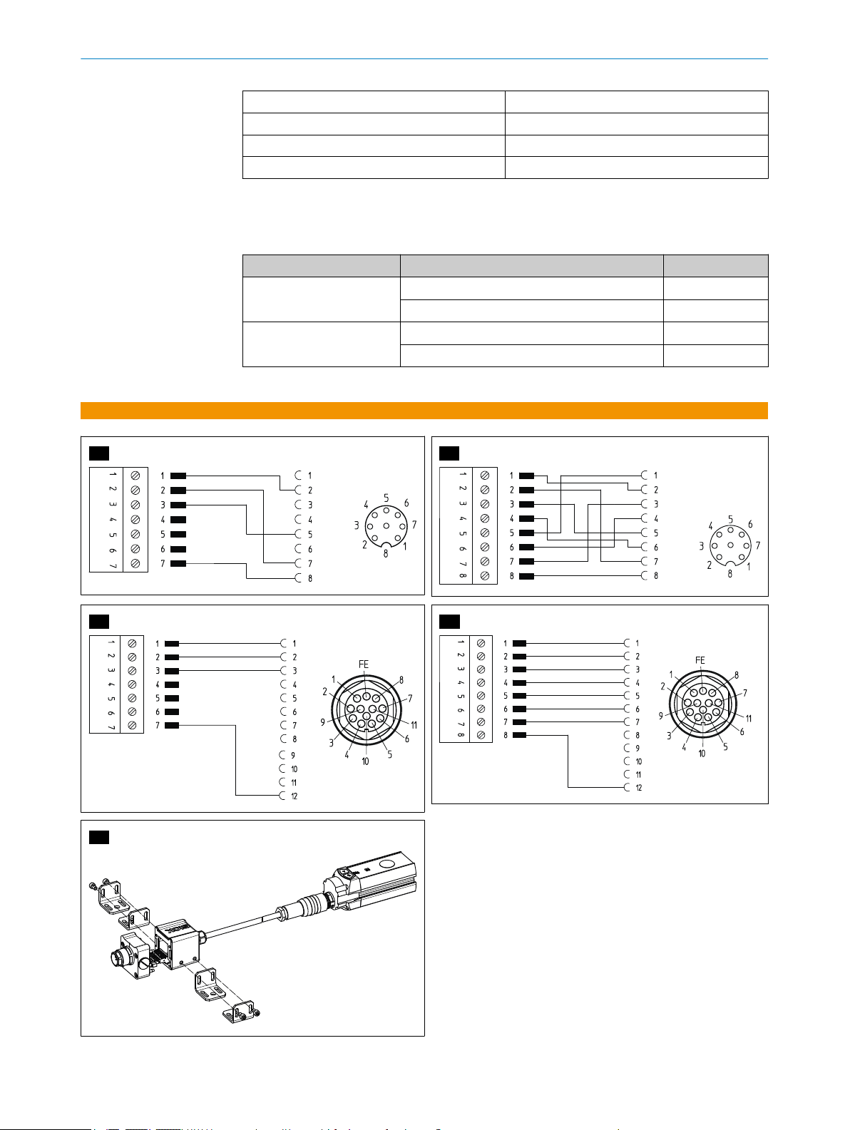
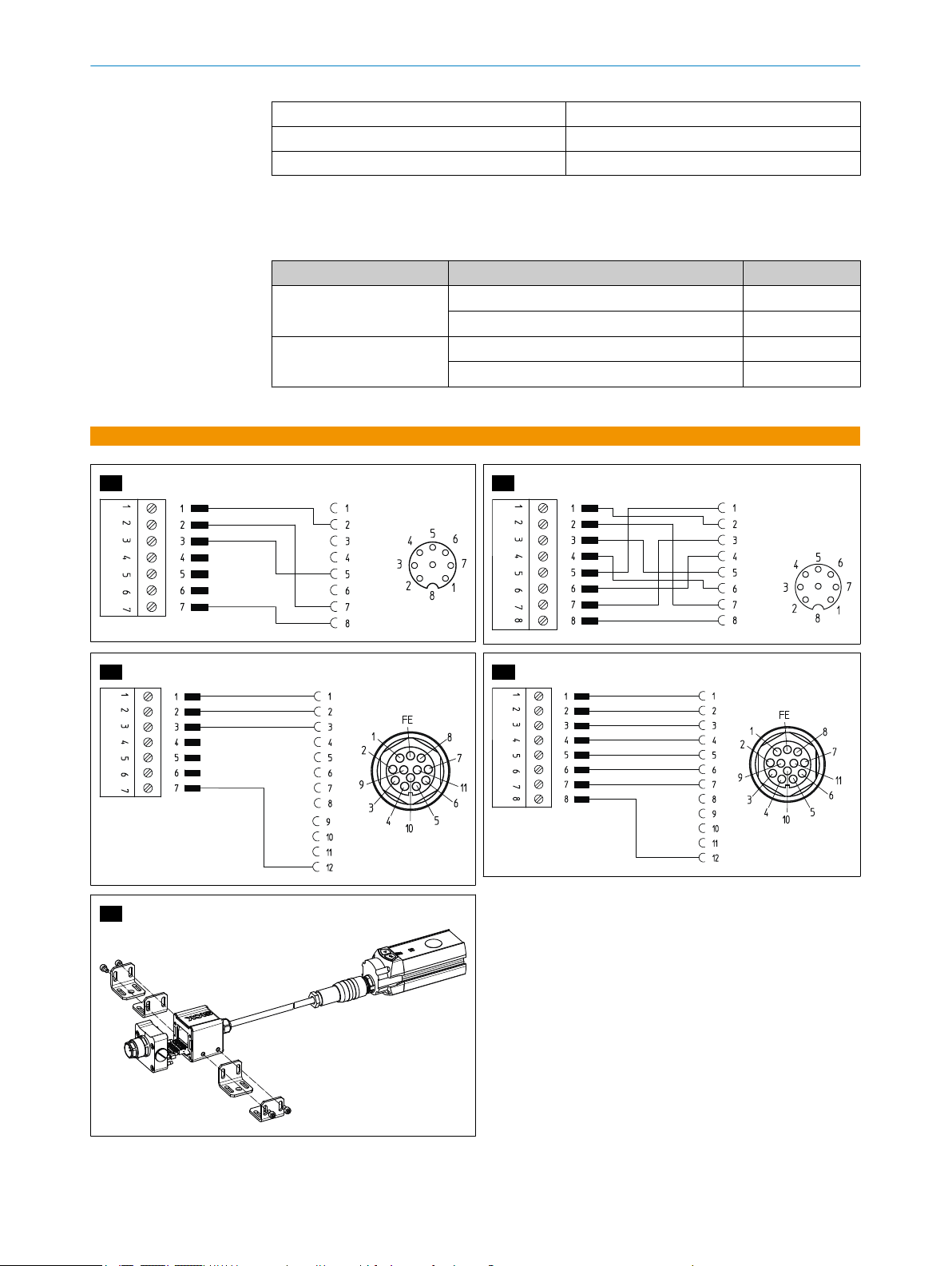
Es gibt vier Varianten des Adapters:
2085501 für Sender M4000 Standard: A1
2085502 für Empfänger M4000 Standard: A2
2085503 für Sender M4000 Advanced: B1
2085504 für Empfänger M4000 Advanced: B2
HINWEIS
Für den Austausch eines Geräts vom Typ MSLZ wird nur ein Adapter für den Empfänger
benötigt. Bei diesem Typ und dem entsprechenden Austauschgerät sind Sende- und
Empfangseinheit in einem Gehäuse.
5 Montage
GEFAHR
Gefahr bringender Zustand der Maschine
Stellen Sie sicher, dass während der Demontage, Montage, Elektroinstallation und
b
Inbetriebnahme der Gefahr bringende Zustand der Maschine ausgeschaltet ist
und bleibt.
Stellen Sie sicher, dass die Ausgänge der Mehrstrahl-Sicherheits-Lichtschranke
b
während der Montage, Elektroinstallation und Inbetriebnahme keine Wirkung auf
die Maschine haben.
8019679/Z425/2016-09-14 | SICK M ON T AG E AN L EI T UN G | Adapter MSL/M4000
Irrtümer und Änderungen vorbehalten
3
Page 4
MONTAGEANLEITUNG
HINWEIS
Bei Austausch einer Mehrstrahl-Sicherheits-Lichtschranke mit MSM-Modul Folgendes
beachten:
1. Beachten, dass das UE403-Modul seitlich neben der Mehrstrahl-Sicherheits-Licht‐
schranke M4000 montiert wird. Das MSM-Modul wurde in einer Linie mit der
Mehrstrahl-Sicherheits-Lichtschranke MSL montiert.
2. Individuell prüfen, ob die vorhandenen Muting-Sensoren weiterhin verwendet wer‐
den können.
1. Mehrstrahl-Sicherheits-Lichtschranke MSL demontieren.
2. Anschlussraum der Mehrstrahl-Sicherheits-Lichtschranke MSL öffnen.
3. Dichtfläche des MSL-Anschlussraums gründlich reinigen, alte Dichtungsreste ent‐
fernen.
4. Bei Empfänger: Steckverbinder (8-Pin) im Anschlussraum des Empfängers mit
Schraubendreher aus Halterung lösen.
5. Steckverbinder des Adapters auf das Gegenstück des MSL-Anschlussraums ste‐
cken.
6. Wenn Mehrstrahl-Sicherheits-Lichtschrank MSL mit MSM-Modul verwendet wurde,
dann beachten, dass Ersatz-Modul UE403 auf andere Weise montiert wird.
7. Gehäuse miteinander verschrauben.
8. Mehrstrahl-Sicherheits-Lichtschranke M4000 montieren.
9. Adapter zwecks Zugentlastung mit dem mitgelieferten Befestigungswinkel befesti‐
gen (4 Möglichkeiten: C1 )
Wenn die Mehrstrahl-Sicherheits-Lichtschranke MSL speziell konfiguriert war (z. B.
b
Reset-Funktion oder EDM), dann sicherstellen, dass die Konfiguration auch bei
M4000 umgesetzt wird.
6 Inbetriebnahme
GEFAHR
Gefahr der Unwirksamkeit der Schutzeinrichtung
Bevor Sie die geschützte Maschine erstmalig in Betrieb nehmen, muss diese
b
durch eine entsprechend befähigte Person überprüft und freigegeben werden.
Nehmen Sie die Maschine nur mit einwandfrei funktionierender Schutzeinrichtung
b
in Betrieb.
Mithilfe der Betriebsanleitung für M4000 sicherstellen, dass der erforderliche
b
Mindestabstand der Mehrstrahl-Lichtschranke zur Gefahrstelle weiterhin eingehal‐
ten wird.
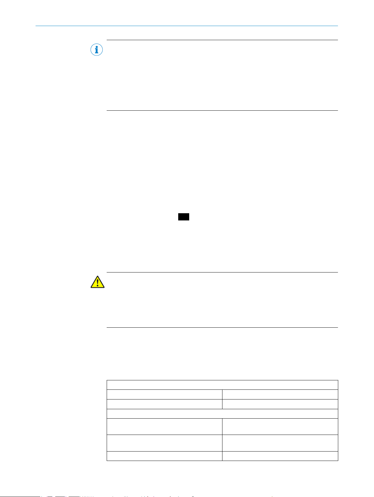
7 Technische Daten
Anschlussart Kopf A
Für Sender (2085501 und 2085503) Dose, Klemmleiste, 7-polig
Für Empfänger (2085502 und 2085504) Dose, Klemmleiste, 8-polig
Anschlussart Kopf B
Für M4000 Standard (2085501 und
2085502)
Für M4000 Advanced (2085503 und
2085504)
Leitungsquerschnitt 0,34 mm
Tabelle 1: Technische Daten
Stecker M12, 8-polig
Stecker M26, 12-polig
2
4
M ON T AG E AN L EI T UN G | Adapter MSL/M4000 8019679/Z425/2016-09-14 | SICK
Irrtümer und Änderungen vorbehalten
Page 5
Abschirmung ungeschirmt
2085501
2085502
2085503
2085504
Bemessungsspannung 60 V
Strombelastbarkeit 4 A
Betriebstemperatur -25 °C ... +70 °C
Tabelle 1: Technische Daten
8 Bestelldaten
MONTAGEANLEITUNG
Produktvariante M4000
Standard
Advanced
Sender oder Empfänger
Sender
Empfänger
Sender
Empfänger
Artikelnummer
2085501
2085502
2085503
2085504
Tabelle 2: Bestelldaten
A1
B1
A2
B2
C1
8019679/Z425/2016-09-14 | SICK M ON T AG E AN L EI T UN G | Adapter MSL/M4000
Irrtümer und Änderungen vorbehalten
5
Page 6
MSL/M4000 adapter
Adapter
M O U N T I N G I N S T R U C T I O N S
de
en
cs
es
fr
pl
zh
Page 7
All rights reserved. Subject to change without notice.
1 About this document
These mounting instructions apply to the MSL/M4000 adapter and only in connection
with the operating instructions for the M4000 multiple light beam safety device.
2 General safety notes
More safety information about actual applications involving the multiple light beam
safety device is available in the corresponding operating instructions.
Make sure that after the replacement, the hazardous area can only be accessed
b
by breaking the light path between sender and receiver.
3 Requirements for the qualification of personnel
The multiple light beam safety device and the MSL/M4000 adapter may only be instal‐
led, commissioned, and maintained by qualified safety personnel.
The same requirements apply as described in the operating instructions for the M4000
multiple light beam safety device.
MOUNTING INSTRUCTIONS
4 Product description
The MSL/M4000 adapter enables an MSL multiple light beam safety device to be
replaced with an M4000 multiple light beam safety device. The adapter links the termi‐
nal compartment of both devices. The existing connecting cable can continue to be
used.
Four variants of the adapter are available:
2085501 for M4000 Standard sender: A1
2085502 for M4000 Standard receiver: A2
2085503 for M4000 Advanced sender: B1
2085504 for M4000 Advanced receiver: B2
NOTE
Only an adapter for the receiver is required when replacing an MSLZ type device. The
sender and receiver unit for this type and the corresponding replacement device are
located inside a single housing.
5 Mounting
DANGER
Dangerous state of the machine
Make sure that the dangerous state of the machine is (and remains) switched off
b
during removal, mounting, electrical installation, and commissioning.
Make sure that the outputs of the multiple light beam safety device do not affect
b
the machine during mounting, electrical installation, and commissioning.
8019679/Z425/2016-09-14 | SICK M O NT A GE A NL E IT U NG | MSL/M4000 adapter
Subject to change without notice
7
Page 8
MOUNTING INSTRUCTIONS
NOTE
When replacing a multiple light beam safety device with MSM module, please note the
following:
1. The UE403 module is mounted adjacent to (at the side of) the M4000 multiple
2. Check each muting sensor individually to ascertain if it can continue to be used.
1. Remove the MSL multiple light beam safety device.
2. Open the terminal compartment of the MSL multiple light beam safety device.
3. Thoroughly clean the sealing surface of the MSL terminal compartment and
4. Receiver: Use a screwdriver to detach the plug connector (8-pin) from the bracket
5. Insert the plug connector of the adapter into the counterpart of the MSL terminal
6. If the MSL multiple light beam safety device was being used with an MSM module,
7. Screw the housings together.
8. Mount the M4000 multiple light beam safety device.
9. Secure the tension relief adapter with the mounting bracket supplied (4 options:
light beam safety device. The MSM module was mounted in a line with the MSL
multiple light beam safety device.
remove any sealing residue.
in the terminal compartment of the receiver.
compartment.
please note that the UE403 replacement module is not mounted in the same way.
C1 ).
If the MSL multiple light beam safety device was configured to perform a specific
b
function (e.g., reset or EDM), make sure that this configuration is transferred to
the M4000.
6 Commissioning
DANGER
Hazard due to lack of effectiveness of the protective device
Before operating the protected machine for the first time, make sure that the
b
machine is first checked and released by qualified safety personnel.
Only operate the machine when the protective device is functioning properly.
b
Refer to the operating instructions for the M4000 to ensure that the required mini‐
b
mum distance between the multiple light beam safety device and the hazardous
point continues to be maintained.
7 Technical data
Head A connection type
For senders (2085501 and 2085503) Female connector, terminal strip, 7-pin
For receivers (2085502 and 2085504) Female connector, terminal strip, 8-pin
Head B connection type
For M4000 Standard (2085501 and
2085502)
For M4000 Advanced (2085503 and
2085504)
Cable cross-section 0.34 mm
Shielding unshielded
Table 3: Technical data
M12 male connector, 8-pin
M26 male connector, 12-pin
2
8
M ON T AG E AN L EI T UN G | MSL/M4000 adapter 8019679/Z425/2016-09-14 | SICK
Subject to change without notice
Page 9
Rated voltage 60 V
2085501
2085502
2085503
2085504
Current carrying capacity 4 A
Operating temperature -25 °C ... +70 °C
Table 3: Technical data
8 Ordering information
MOUNTING INSTRUCTIONS
M4000 product type
Standard
Advanced
Sender or receiver
Sender
Receiver
Sender
Receiver
Part number
2085501
2085502
2085503
2085504
Table 4: Ordering information
A1
B1
A2
B2
C1
8019679/Z425/2016-09-14 | SICK M O NT A GE A NL E I TU N G | MSL/M4000 adapter
Subject to change without notice
9
Page 10

Adaptér MSL/M4000
Adaptér
M O N T Á Ž N Í N Á V O D
de
en
cs
es
fr
pl
zh
Page 11

Všechna práva vyhrazena. Omyly a změny vyhrazeny.
1 K tomuto dokumentu
Tento montážní návod platí pro adaptér MSL/M4000 a jen ve spojení s provozním návo‐
dem pro vícepaprskovou bezpečnostní světelnou mříž M4000.
2 Základní bezpečnostní upozornění
Další bezpečnostní informace týkající se konkrétních situací při použití vícepaprskové
bezpečnostní světelné mříže naleznete v příslušném provozním návodu.
Zajistěte, aby byl po výměně nebezpečný prostor přístupný jen s přerušením svě‐
b
telné dráhy mezi vysílačem a přijímačem.
3 Požadavky na kvalifikaci personálu
Vícepaprsková bezpečnostní světelná mříž a adaptér MSL/M4000 smí instalovat, uvést
do provozu a provádět jejich údržbu jen oprávněné osoby.
Platí stejné požadavky, které jsou definované v provozním návodu pro vícepaprskovou
bezpečnostní světelnou mříž M4000.
MONTÁŽNÍ NÁVOD
4 Popis výrobku
Adaptér MSL/M4000 umožňuje výměnu vícepaprskové bezpečnostní světelné mříže
MSL za vícepaprskovou bezpečnostní světelnou mříž M4000. Adaptér vzájemně propo‐
juje připojovací prostory obou přístrojů. Stávající připojovací kabely můžete dále použí‐
vat.
K dispozici jsou čtyři varianty adaptéru:
2085501 pro vysílač M4000 Standard: A1
2085502 pro přijímač M4000 Standard: A2
2085503 pro vysílač M4000 Advanced: B1
2085504 pro přijímač M4000 Advanced: B2
POZNÁMKA
Pro výměnu přístroje typu MSLZ je nutný jen adaptér pro přijímač. U tohoto typu a odpo‐
vídajícího náhradního přístroje jsou vysílací a přijímací jednotka v jednom pouzdru.
5 Montáž
NEBEZPEČÍ
Nebezpečný stav stroje
b
b
Zajistěte, aby stroj byl a zůstal během demontáže, montáže, elektroinstalace a
uvedení do provozu vypnutý.
Zajistěte, aby výstupy vícepaprskové bezpečnostní světelné mříže neměly během
montáže, elektroinstalace a uvedení do provozu žádný vliv na stroj.
8019679/Z425/2016-09-14 | SICK M ON T AG E AN L EI T UN G | Adaptér MSL/M4000
Práva na změnu vyhrazena
11
Page 12

MONTÁŽNÍ NÁVOD
POZNÁMKA
Při výměně vícepaprskové bezpečnostní světelné mříže s modulem MSM dodržujte
následující instrukce:
1. Dbejte na to, aby byl modul UE403 namontován bočně vedle vícepaprskové bez‐
pečnostní světelné mříže M4000. Modul MSM byl namontován v jedné řadě
s vícepaprskovou bezpečnostní světelnou mříží MSL.
2. Individuálně zkontrolujte, zda lze i nadále použít stávající mutingové senzory.
1. Demontujte vícepaprskovou bezpečnostní světelnou mříž MSL.
2. Otevřete připojovací prostor vícepaprskové bezpečnostní světelné mříže MSL.
3. Důkladně očistěte těsnicí plochu připojovacího prostoru MSL, odstraňte zbytky sta‐
rého těsnění.
4. U přijímače: pomocí šroubováku uvolněte konektor (8pinový) přijímače z držáku.
5. Připojte konektor adaptéru k protikusu připojovacího prostoru MSL.
6. Pokud byla použita vícepaprsková bezpečnostní světelná mříž MSL s modulem
MSM, dbejte na to, že náhradní modul UE403 se montuje jiným způsobem.
7. Sešroubujte pouzdro.
8. Namontujte vícepaprskovou bezpečnostní světelnou mříž M4000.
9. Adaptér pro odlehčení tahu upevněte pomocí přiloženého montážního držáku
(4 možnosti: C1 )
Pokud byla vícepaprsková bezpečnostní světelná mříž MSL speciálně konfiguro‐
b
vána (např. funkce reset nebo EDM), zajistěte, aby tato konfigurace byla prove‐
dena také u M4000.
6 Uvedení do provozu
NEBEZPEČÍ
Nebezpečí neúčinnosti ochranného zařízení
Než uvedete chráněný stroj poprvé do provozu, musí jej přezkoušet a uvolnit k pro‐
b
vozu oprávněná osoba.
Uveďte stroj do provozu jen s bezvadně fungujícím ochranným zařízením.
b
Pomocí provozního návodu pro M4000 zajistěte, aby byla i nadále dodržena
b
potřebná minimální vzdálenost vícepaprskové bezpečnostní světelné mříže od
nebezpečného místa.
7 Technické údaje
Druh připojení kódování A
Pro vysílač (2085501 a 2085503) Zásuvka, svorkovnice, 7pinová
Pro přijímač (2085502 a 2085504) Zásuvka, svorkovnice, 8pinová
Druh připojení kódování B
Pro M4000 Standard (2085501 a
2085502)
Pro M4000 Advanced (2085503 a
2085504)
Průřez vodiče 0,34 mm
Stínění nestíněný
Nominální napětí 60 V
Proudová zatížitelnost 4 A
Tabulka 5: Technické údaje
Zástrčka M12, 8pinová
Zástrčka M26, 12pinová
2
12
M ON T AG E AN L EI T UN G | Adaptér MSL/M4000 8019679/Z425/2016-09-14 | SICK
Práva na změnu vyhrazena
Page 13

Provozní teplota –25 °C ... +70 °C
2085501
2085502
2085503
2085504
Tabulka 5: Technické údaje
8 Objednací údaje
MONTÁŽNÍ NÁVOD
Varianta produktu M4000
Standard
Advanced
Vysílač nebo přijímač
Vysílač
Přijímač
Vysílač
Přijímač
Objednací číslo
2085501
2085502
2085503
2085504
Tabulka 6: Objednací údaje
A1
B1
A2
B2
C1
8019679/Z425/2016-09-14 | SICK M ON T AG E AN L EI T UN G | Adaptér MSL/M4000
Práva na změnu vyhrazena
13
Page 14

Adaptador MSL/M4000
Adaptador
I N S T R U C C I O N E S D E M O N T A J E
de
en
cs
es
fr
pl
zh
Page 15

Todos los derechos reservados. Sujeto a cambio sin previo aviso.
1 Acerca de este documento
Estas instrucciones de montaje se aplican al adaptador MSL/M4000 y solo en combi‐
nación con las instrucciones de uso de la barrera fotoeléctrica de seguridad multihaz
M4000.
2 Indicaciones básicas de seguridad
Las instrucciones de uso asociadas contienen información de seguridad adicional rela‐
cionada con situaciones de uso específicas de la barrera fotoeléctrica de seguridad
multihaz.
Asegúrese de que, después de realizar la sustitución, la zona de peligro solo es
b
accesible interrumpiendo la trayectoria de la luz entre el emisor y el receptor.
3 Requisitos de cualificación del personal
El montaje, la puesta en servicio y el mantenimiento de la barrera fotoeléctrica de
seguridad multihaz y del adaptador MSL/M4000 solo deben realizarlos personas auto‐
rizadas.
INSTRUCCIONES DE MONTAJE
Se aplican los mismos requisitos que los descritos en las instrucciones de uso de la
barrera fotoeléctrica de seguridad multihaz M4000.
4 Descripción de producto
El adaptador MSL/M4000 permite sustituir una barrera fotoeléctrica de seguridad mul‐
tihaz MSL por una barrera fotoeléctrica de seguridad multihaz M4000. El adaptador
conecta entre sí las cajas de conexión de los dos dispositivos. El cable de conexión
existente puede seguir utilizándose.
Hay cuatro variantes del adaptador:
2085501 para emisor M4000 Standard: A1
2085502 para receptor M4000 Standard: A2
2085503 para emisor M4000 Advanced: B1
2085504 para receptor M4000 Advanced: B2
INDICACIÓN
Para sustituir un dispositivo del tipo MSLZ, solo es necesario un adaptador para el
receptor. En este tipo y en el dispositivo de sustitución correspondiente, la unidad de
emisión y de recepción se encuentran en la misma carcasa.
8019679/Z425/2016-09-14 | SICK M ON T AG E AN L EI T UN G | Adaptador MSL/M4000
Sujeto a cambio sin previo aviso
15
Page 16

INSTRUCCIONES DE MONTAJE
5 Montaje
PELIGRO
Estado con potencial de riesgo de la máquina
Asegúrese de que el estado con potencial de riesgo de la máquina esté y perma‐
b
nezca desconectado durante el desmontaje, el montaje, la instalación eléctrica y
la puesta en servicio.
Asegúrese de que las salidas de la barrera fotoeléctrica de seguridad multihaz no
b
tengan ningún efecto sobre la máquina durante el montaje, la instalación eléctrica
y la puesta en servicio.
INDICACIÓN
Para sustituir una barrera fotoeléctrica de seguridad multihaz con el módulo MSM,
deberá tenerse en cuenta lo siguiente:
1. Tenga en cuenta que el módulo UE403 se monta lateralmente junto a la barrera
fotoeléctrica de seguridad multihaz M4000. El módulo MSM se ha montado ali‐
neado con la barrera fotoeléctrica de seguridad multihaz MSL.
2. Compruebe individualmente si los sensores de muting existentes pueden seguir
usándose.
1. Desmonte la barrera fotoeléctrica de seguridad multihaz MSL.
2. Abra la caja de conexión de la barrera fotoeléctrica de seguridad multihaz MSL.
3. Limpie a fondo la superficie hermetizante de la caja de conexión de la MSL y retire
los restos de junta.
4. En el receptor: suelte del soporte el conector de enchufe (8 terminales) de la caja
de conexión del receptor con un destornillador.
5. Inserte el conector de enchufe del adaptador en su contraparte de la caja de
conexión de la barrera MSL.
6. Si la barrera fotoeléctrica de seguridad multihaz MSL se usó con el módulo MSM,
deberá tener en cuenta que el módulo de sustitución UE403 se monta de otro
modo.
7. Atornille las carcasas entre sí.
8. Monte la barrera fotoeléctrica de seguridad multihaz M4000.
9. Con el fin de descargar la tracción, fije el adaptador con la escuadra de fijación
suministrada (4 posibilidades:
Si la barrera fotoeléctrica de seguridad multihaz MSL estaba configurada de
b
forma especial, (p. ej., función Reset o EDM), asegúrese de que la configuración
también se implementa en la M4000.
6 Puesta en servicio
PELIGRO
Riesgo por falta de efectividad del dispositivo de protección
C1 )
16
Antes de poner en servicio por primera vez la máquina protegida, una persona
b
debidamente autorizada deberá encargarse de revisarla y autorizarla.
Ponga en funcionamiento la máquina únicamente con un dispositivo de protec‐
b
ción perfectamente operativo.
Use las instrucciones de uso de M4000 para asegurarse de que se sigue mante‐
b
niendo la distancia mínima entre la barrera fotoeléctrica multihaz y el punto de
peligro.
M ON T AG E AN L EI T UN G | Adaptador MSL/M4000 8019679/Z425/2016-09-14 | SICK
Sujeto a cambio sin previo aviso
Page 17

7 Datos técnicos
2085501
2085502
Tipo de conexión cabezal A
Para emisor (2085501 y 2085503) Conector hembra, regleta de conexión de 7
Para receptor (2085502 y 2085504) Conector hembra, regleta de conexión de 8
Tipo de conexión cabezal B
Para M4000 Standard (2085501 y
2085502)
Para M4000 Advanced (2085503 y
2085504)
Sección de cable 0,34 mm
Apantallamiento sin apantallar
Tensión asignada 60 V
Intensidad de corriente máxima admisible 4 A
Temperatura de servicio -25 °C … +70 °C
Tabla 7: Datos técnicos
INSTRUCCIONES DE MONTAJE
polos
polos
Conector macho M12 de 8 polos
Conector macho M26 de 12 polos
2
8 Datos de pedido
Variante de producto
M4000
Standard
Advanced
Tabla 8: Datos de pedido
A1
Emisor o receptor
Emisor
Receptor
Emisor
Receptor
A2
Referencia
2085501
2085502
2085503
2085504
8019679/Z425/2016-09-14 | SICK M ON T AG E AN L EI T UN G | Adaptador MSL/M4000
Sujeto a cambio sin previo aviso
17
Page 18

2085503
2085504
INSTRUCCIONES DE MONTAJE
B1
C1
B2
18
M ON T AG E AN L EI T UN G | Adaptador MSL/M4000 8019679/Z425/2016-09-14 | SICK
Sujeto a cambio sin previo aviso
Page 19

Adaptateur MSL/M4000
Adaptateur
N O T I C E D E M O N T A G E
de
en
cs
es
fr
pl
zh
Page 20

NOTICE DE MONTAGE
Tous droits réservés. Sujet à modification sans préavis.
1 À propos de ce document
Cette notice de montage s'applique à l'adaptateur MSL/M4000 et uniquement avec la
notice d'instruction pour la barrière photoélectrique de sécurité multifaisceaux M4000.
2 Consignes de sécurité générales
Vous trouverez des informations de sécurité plus précises pour chaque application de
la barrière photoélectrique de sécurité multifaisceaux dans la notice d'instruction cor‐
respondante.
Après le remplacement, assurez-vous que la zone dangereuse soit accessible uni‐
b
quement en franchissant le chemin optique entre l'émetteur et le récepteur.
3 Exigences relatives aux qualifications du personnel
La barrière photoélectrique de sécurité multifaisceaux et l'adaptateur MSL/M4000 ne
doivent être installés, mis en service et entretenus que par le personnel qualifié.
Les exigences sont les mêmes que celles décrites dans la notice d'instruction de la bar‐
rière photoélectrique de sécurité multifaisceaux M4000.
4 Description du produit
L'adaptateur MSL/M4000 permet de remplacer une barrière photoélectrique de sécu‐
rité multifaisceaux MSL par une barrière photoélectrique de sécurité multifaisceaux
M4000. L'adaptateur relie les compartiments de raccordement des deux appareils. Le
câble de raccordement existant peut être réutilisé.
L'adaptateur se décline en quatre versions :
2085501 pour émetteur M4000 Standard : A1
2085502 pour récepteur M4000 Standard : A2
2085503 pour émetteur M4000 Advanced : B1
2085504 pour récepteur M4000 Advanced : B2
REMARQUE
Un seul adaptateur est nécessaire pour le récepteur lors du remplacement d'un appa‐
reil de type MSLZ. Avec ce type d'appareil et l'appareil de rechange correspondant,
l'émetteur et le récepteur se trouvent dans un même boîtier.
5 Montage
20
DANGER
Situation dangereuse de la machine
Assurez-vous que la situation dangereuse de la machine est supprimée et qu'elle
b
le reste pendant le démontage, le montage, l'installation électrique et la mise en
service.
Assurez-vous que les sorties de la barrière photoélectrique de sécurité multifais‐
b
ceaux n'ont aucune action sur la machine pendant le montage, l'installation élec‐
trique et la mise en service.
M ON T AG E AN L EI T UN G | Adaptateur MSL/M4000 8019679/Z425/2016-09-14 | SICK
Sujet à modification sans préavis
Page 21

NOTICE DE MONTAGE
REMARQUE
En cas de remplacement d'une barrière photoélectrique de sécurité multifaisceaux
avec module MSM, respecter les instructions suivantes :
1. S'assurer que le module UE403 est monté latéralement à côté de la barrière pho‐
toélectrique de sécurité multifaisceaux M4000. Le module MSM a été monté sur
une ligne avec la barrière photoélectrique de sécurité multifaisceaux MSL.
2. Vérifier si les capteurs d'inhibition (muting) peuvent toujours être utilisés.
1. Démonter la barrière photoélectrique de sécurité multifaisceaux MSL.
2. Ouvrir le compartiment de raccordement de la barrière photoélectrique de sécu‐
rité multifaisceaux MSL.
3. Nettoyer soigneusement la surface du compartiment de raccordement MSL et éli‐
miner les résidus de joint.
4. Pour le récepteur : détacher de la fixation le connecteur enfichable (8 broches)
situé dans le compartiment de raccordement du récepteur à l'aide d'un tournevis.
5. Brancher le connecteur enfichable de l'adaptateur dans la pièce correspondante
du compartiment de raccordement MSL.
6. Si la barrière photoélectrique de sécurité multifaisceaux MSL est utilisée avec le
module MSM, s'assurer que le module de rechange UE403 est monté différem‐
ment.
7. Visser les boîtiers ensemble.
8. Monter la barrière photoélectrique de sécurité multifaisceaux M4000.
9. Fixer l'adaptateur avec l'équerre de fixation fournie pour réduire la force de trac‐
tion (quatre possibilités, voir C1 )
Si la barrière photoélectrique de sécurité multifaisceaux MSL a été spécialement
b
configurée (par ex. fonction de réinitialisation ou EDM), s'assurer que la configura‐
tion est appliquée au M4000.
6 Mise en service
DANGER
Risque lié au non fonctionnement d’un dispositif de protection
Avant la première mise en service d'une machine, le personnel qualifié doit tester
b
la machine et la valider.
Mettez la machine en service uniquement si le dispositif de protection fonctionne
b
correctement.
Avec la notice d'instruction du M4000, veiller à respecter la distance minimale
b
entre la barrière multifaisceaux et le point dangereux.
7 Caractéristiques techniques
Mode de raccordement côté A
Pour émetteurs (2085501 et 2085503) Connecteur femelle, bornier, 7 pôles
Pour récepteurs (2085502 et 2085504) Connecteur femelle, bornier, 8 pôles
Mode de raccordement côté B
Pour M4000 Standard (2085501 et
2085502)
Pour M4000 Advanced (2085503 et
2085504)
Section de câble 0,34 mm
Tableau 9: Caractéristiques techniques
Connecteur mâle M12, 8 pôles
Connecteur mâle M26, 12 pôles
2
8019679/Z425/2016-09-14 | SICK MO NT A GE A NL E IT U NG | Adaptateur MSL/M4000
Sujet à modification sans préavis
21
Page 22

2085501
2085502
2085503
2085504
NOTICE DE MONTAGE
Blindage non blindé
Tension de mesure 60 V
Charge électrique 4 A
Température de fonctionnement -25 °C à +70 °C
Tableau 9: Caractéristiques techniques
8 Données pour commander
Variante de produit M4000
Standard
Advanced
Émetteur ou récepteur
Émetteur
Récepteur
Émetteur
Récepteur
Référence
2085501
2085502
2085503
2085504
Tableau 10: Données pour commander
A1
B1
A2
B2
22
C1
M ON T AG E AN L EI T UN G | Adaptateur MSL/M4000 8019679/Z425/2016-09-14 | SICK
Sujet à modification sans préavis
Page 23

Adapter MSL/M4000
Adapter
I N S T R U K C J A M O N T A Ż U
de
en
cs
es
fr
pl
zh
Page 24

INSTRUKCJA MONTAŻU
Wszelkie prawa zastrzeżone. Informacje mogą ulec zmianie bez powiadomienia
1 Informacje o tym dokumencie
Niniejsza instrukcja montażu dotyczy adaptera MSL/M4000 i obowiązuje wyłącznie
w połączeniu z instrukcją eksploatacji wielowiązkowej bariery bezpieczeństwa M4000.
2 Podstawowe instrukcje bezpieczeństwa
Więcej informacji na temat bezpieczeństwa podczas użytkowania wielowiązkowej
bariery bezpieczeństwa można znaleźć w odpowiedniej instrukcji eksploatacji.
Należy się upewnić, że po wymianie urządzenia dostęp do obszaru zagrożenia jest
b
możliwy tylko po przerwaniu wiązki świetlnej między nadajnikiem i odbiornikiem.
3 Wymagania dotyczące kwalifikacji personelu
Wielowiązkowa bariera bezpieczeństwa i adapter MSL/M4000 mogą być montowane,
uruchamiane i konserwowane wyłącznie przez wykwalifikowanych pracowników.
Obowiązują takie same wymagania jak te opisane w instrukcji eksploatacji wielowiązko‐
wej bariery bezpieczeństwa M4000.
4 Opis produktu
Adapter MSL/M4000 umożliwia zastąpienie wielowiązkowej bariery bezpieczeństwa
MSL wielowiązkową barierą bezpieczeństwa M4000. Adapter łączy ze sobą komory
przyłączeniowe obu urządzeń. Dostępny przewód podłączeniowy może być nadal stoso‐
wany.
Dostępne są cztery warianty adaptera:
2085501 do nadajnika M4000 Standard: A1
2085502 do odbiornika M4000 Standard: A2
2085503 do nadajnika M4000 Advanced: B1
2085504 do odbiornika M4000 Advanced: B2
WSKAZÓWKA
Do wymiany urządzenia typu MSLZ wymagany jest tylko jeden adapter dla odbiornika.
W przypadku tego typu i odpowiedniego urządzenia zamiennego moduł nadawczy
i moduł odbiorczy znajdują się w jednej obudowie.
5 Montaż
NIEBEZPIECZEŃSTWO
Niebezpieczny stan maszyny
24
Upewnić się, że podczas demontażu, montażu, podłączania do instalacji elektrycz‐
b
nej i uruchamiania niebezpieczny stan maszyny jest wyłączony i taki pozostaje.
Upewnić się, że wyjścia wielowiązkowej bariery bezpieczeństwa podczas montażu,
b
podłączania do instalacji elektrycznej i uruchamiania nie mają wpływu na
maszynę.
M ON T AG E AN L EI T UN G | Adapter MSL/M4000 8019679/Z425/2016-09-14 | SICK
Z zastrzeżeniem zmiany bez powiadomienia
Page 25

INSTRUKCJA MONTAŻU
WSKAZÓWKA
Podczas wymiany wielowiązkowej bariery bezpieczeństwa z modułem MSM należy prze‐
strzegać następujących instrukcji:
1. Zwrócić uwagę, aby moduł UE403 został zamontowany z boku obok wielowiązko‐
wej bariery bezpieczeństwa M4000. Zamontowany moduł MSM i wielowiązkowa
bariera bezpieczeństwa MSL muszą się znajdować w jednej linii.
2. Sprawdzić, czy istniejące czujniki mutingu mogą być w dalszym ciągu używane.
1. Zdemontować wielowiązkową barierę bezpieczeństwa MSL.
2. Otworzyć komorę przyłączeniową wielowiązkowej bariery bezpieczeństwa MSL.
3. Starannie wyczyścić powierzchnię uszczelniającą komory przyłączeniowej MSL
i usunąć pozostałości uszczelnienia.
4. Odbiornik: odkręcić złącze wtykowe (8-pinowe) w komorze przyłączeniowej odbior‐
nika od uchwytu, używając wkrętaka.
5. Podłączyć złącze wtykowe adaptera do odpowiednika w komorze przyłączeniowej
urządzenia MSL.
6. Jeśli wielowiązkowa bariera bezpieczeństwa MSL została użyta z modułem MSM,
zwrócić uwagę, aby moduł zamienny UE403 został zamontowany w inny sposób.
7. Skręcić ze sobą obudowy.
8. Zamontować wielowiązkową barierę bezpieczeństwa M4000.
9. W celu odciążenia zamocować adapter za pomocą dołączonego do zestawu uch‐
wytu montażowego (4 możliwości: C1 )
Jeśli wielowiązkowa bariera bezpieczeństwa MSL została specjalnie skonfiguro‐
b
wana (np. funkcja reset lub monitorowanie urządzeń zewnętrznych), upewnić się,
że konfiguracja ta zostanie zastosowana także w przypadku urządzenia M4000.
6 Uruchomienie
NIEBEZPIECZEŃSTWO
Ryzyko nieskutecznego działania urządzenia ochronnego
Przed pierwszym uruchomieniem maszyny, chronionej przez kurtynę świetlną bez‐
b
pieczeństwa, konieczne jest sprawdzenie maszyny i dopuszczenie jej do eksploata‐
cji przez wykwalifikowanego pracownika.
Uruchomić maszynę tylko wtedy, gdy urządzenie zabezpieczające jest sprawne.
b
Korzystając z instrukcji eksploatacji urządzenia M4000, upewnić się, że w dalszym
b
ciągu zachowany jest odstęp minimalny wielowiązkowej bariery bezpieczeństwa od
miejsca niebezpiecznego.
7 Dane techniczne
Typ przyłącza – głowica A
Dla nadajnika (2085501 i 2085503) Złącze żeńskie, listwa zaciskowa, 7-pinowa
Dla odbiornika (2085502 i 2085504) Złącze żeńskie, listwa zaciskowa, 8-pinowa
Typ przyłącza – głowica B
Dla M4000 Standard (2085501 i 2085502) Wtyk M12, 8-pinowy
Dla M4000 Advanced (2085503
i 2085504)
Przekrój przewodu 0,34 mm
Ekranowanie nieekranowany
Tabela 11: Dane techniczne
Wtyk M26, 12-pinowy
2
8019679/Z425/2016-09-14 | SICK M ON T AG E AN L EI T UN G | Adapter MSL/M4000
Z zastrzeżeniem zmiany bez powiadomienia
25
Page 26

2085501
2085502
2085503
2085504
INSTRUKCJA MONTAŻU
Napięcie znamionowe 60 V
Obciążalność prądowa 4 A
Temperatura robocza –25°C ... +70°C
Tabela 11: Dane techniczne
8 Dane zamówienia
Wariant produktu M4000
Nadajnik lub odbiornik
Numer katalo‐
gowy
Standard
Advanced
Nadajnik
Odbiornik
Nadajnik
Odbiornik
2085501
2085502
2085503
2085504
Tabela 12: Dane zamówienia
A1
B1
A2
B2
26
C1
M ON T AG E AN L EI T UN G | Adapter MSL/M4000 8019679/Z425/2016-09-14 | SICK
Z zastrzeżeniem zmiany bez powiadomienia
Page 27

MSL/M4000 适配器
适配器
安 装 说 明 书
de
en
cs
es
fr
pl
zh
Page 28

安装说明书
版权所有。如有更改,恕不另行通知。
1 关于本文档
本安装说明书适用于 MSL/M4000 适配器且只与 M4000 多光束安全光栅的操作指
南共同使用。
2 基本安全注意事项
关于多光束安全光栅具体用途的详细安全信息请参见相应章节。
请在更换后确保仅可通过中断发射器与接收器之间的光路来接近危险区域。
b
3 合格的安全人员
多光束安全光栅和 MSL/M4000 适配器只允许由具备相关资质的人员安装、运行和
保养。
适用于 M4000 多光束安全光栅的操作指南中所述的相同要求。
4
5
产品描述
安装
MSL/M4000 适配器能用 M4000 多光束安全光栅代替 MSL 多光束安全光栅。适配
器连接了两个设备的连接区域。现有的连接电缆可继续使用。
提供四种适配器变型:
2085501,M4000 Standard 发射器:
2085502,M4000 Standard 接收器:
2085503,M4000 Advanced 发射器:
2085504,M4000 Advanced 接收器:
提示
更换 MSLZ 类型的设备仅需要一个接收器适配器。在该类型及相应的更换设备中,
发射与接收单元处于同一外壳内。
危险
机器危险状态
请确保在拆卸、安装、电气连接和调试期间机器始终处于无危险状态。
b
请确保多光束安全光栅的输出在安装、电气连接和调试时并不影响机器运转。
b
A1
A2
B1
B2
28
提示
更换多光束安全光栅及 MSM 模块时请注意下列事项:
1. 请注意,UE403 模块安装在 M4000 多光束安全光栅的侧面。MSM 模块与
MSL 多光束安全光栅安装于一条直线上。
2. 分别检查现有的屏蔽型传感器是否能继续使用。
1. 拆除 MSL 多光束安全光栅。
2. 打开 MSL 多光束安全光栅的连接区域。
3. 彻底清洁 MSL 连接区域的密封面,清除之前的密封残留物。
4. 接收器:采用螺丝刀从支架上松开接收器连接区域内的插塞接头(8 针)。
M ON T AG E AN L EI T UN G | MSL/M4000 适配器 8019679/Z425/2016-09-14 | SICK
如有更改,恕不另行通知
Page 29

安装说明书
5. 将适配器的插塞接头插入 MSL 连接区域的对应位置。
6. 如果已使用 MSL 多光束安全光栅及 MSM 模块,请注意以其他方式安装
UE403 替换模块。
7. 将外壳互相拧紧。
8. 安装 M4000 多光束安全光栅。
9. 为减小张力,采用随附的安装支架固定适配器(4 种方式: C1 )
如果 MSL 多光束安全光栅已经过专门配置(例如复位功能或 EDM),则请确
b
保该配置也可应用在 M4000 中。
6
调试
危险
防护设备失效的危险
首次操作受保护的机器之前,必须确保该机器先由合格的安全人员进行检查和
b
放行。
仅在安全光幕的保护功能正常运行的情况下才能操作机器。
b
通过 M4000 操作指南,确保始终遵守多光束光电传感器与作业危险点所需的
b
最小距离。
7
技术参数
连接方式 A 头
用于发射器(2085501 与 2085503) 插座,端子板,7 针
用于接收器(2085502 与 2085504) 插座,端子板,8 针
连接方式 B 头
用于 M4000 Standard(2085501 与
2085502)
用于 M4000 Advanced(2085503 与
2085504)
电缆截面 0.34 mm
屏蔽 无屏蔽
测定电压 60 V
载流能力 4 A
工作温度 -25 °C ~ +70 °C
表格 13: 技术参数
M12 8 针插头
M26 12 针插头
2
8 订购信息
M4000 产品变型
标准
先进的
表格 14: 订购信息
8019679/Z425/2016-09-14 | SICK MO N TA G EA N LE I TU N G | MSL/M4000 适配器
如有更改,恕不另行通知
发射器或 接收器
发射器
接收器
发射器
接收器
订货号
2085501
2085502
2085503
2085504
29
Page 30

2085501
2085502
2085503
2085504
安装说明书
A1
B1
C1
A2
B2
30
M ON T AG E AN L EI T UN G | MSL/M4000 适配器 8019679/Z425/2016-09-14 | SICK
如有更改,恕不另行通知
Page 31

安装说明书
8019679/Z425/2016-09-14 | SICK MO N TA G EA N LE I TU N G | MSL/M4000 适配器
如有更改,恕不另行通知
31
Page 32

Australia
Phone +61 3 9457 0600
1800 334 802 – tollfree
E-Mail sales@sick.com.au
Austria
Phone +43 22 36 62 28 8-0
E-Mail office@sick.at
Belgium/Luxembourg
Phone +32 2 466 55 66
E-Mail info@sick.be
Brazil
Phone +55 11 3215-4900
E-Mail marketing@sick.com.br
Canada
Phone +1 905 771 14 44
E-Mail information@sick.com
Czech Republic
Phone +420 2 57 91 18 50
E-Mail sick@sick.cz
Chile
Phone +56 2 2274 7430
E-Mail info@schadler.com
China
Phone +86 20 2882 3600
E-Mail info.china@sick.net.cn
Denmark
Phone +45 45 82 64 00
E-Mail sick@sick.dk
Finland
Phone +358-9-2515 800
E-Mail sick@sick.fi
France
Phone +33 1 64 62 35 00
E-Mail info@sick.fr
Germany
Phone +49 211 5301-301
E-Mail info@sick.de
Hong Kong
Phone +852 2153 6300
E-Mail ghk@sick.com.hk
Hungary
Phone +36 1 371 2680
E-Mail office@sick.hu
India
Phone +91 22 4033 8333
E-Mail info@sick-india.com
Israel
Phone +972 4 6881000
E-Mail info@sick-sensors.com
Italy
Phone +39 02 274341
E-Mail info@sick.it
Japan
Phone +81 3 5309 2112
E-Mail support@sick.jp
Malaysia
Phone +6 03 8080 7425
E-Mail enquiry.my@sick.com
Mexico
Phone +52 472 748 9451
E-Mail mario.garcia@sick.com
Netherlands
Phone +31 30 2044 000
E-Mail info@sick.nl
New Zealand
Phone +64 9 415 0459
0800 222 278 – tollfree
E-Mail sales@sick.co.nz
Norway
Phone +47 67 81 50 00
E-Mail sick@sick.no
Poland
Phone +48 22 539 41 00
E-Mail info@sick.pl
Romania
Phone +40 356 171 120
E-Mail office@sick.ro
Russia
Phone +7 495 775 05 30
E-Mail info@sick.ru
Singapore
Phone +65 6744 3732
E-Mail sales.gsg@sick.com
Slovakia
Phone +421 482 901201
E-Mail mail@sick-sk.sk
Slovenia
Phone +386 591 788 49
E-Mail office@sick.si
South Africa
Phone +27 11 472 3733
E-Mail info@sickautomation.co.za
South Korea
Phone +82 2 786 6321
E-Mail info@sickkorea.net
Spain
Phone +34 93 480 31 00
E-Mail info@sick.es
Sweden
Phone +46 10 110 10 00
E-Mail info@sick.se
Switzerland
Phone +41 41 619 29 39
E-Mail contact@sick.ch
Taiwan
Phone +886 2 2375-6288
E-Mail sales@sick.com.tw
Thailand
Phone +66 2645 0009
E-Mail Ronnie.Lim@sick.com
Turkey
Phone +90 216 528 50 00
E-Mail info@sick.com.tr
United Arab Emirates
Phone +971 4 88 65 878
E-Mail info@sick.ae
United Kingdom
Phone +44 1727 831121
E-Mail info@sick.co.uk
USA
Phone +1 800 325 7425
E-Mail info@sick.com
Vietnam
Phone +84 945452999
E-Mail Ngo.Duy.Linh@sick.com
Further locations at www.sick.com
8019679/Z425/2016-09-14/de/de, en, cs, es, fr, pl, zh
SICK AG | Waldkirch | Germany | www.sick.com
 Loading...