

Page 1

MLP1
Safety switch
O P E R A T I N G I N S T R U C T I O N S
Page 2

Described product
MLP1
Manufacturer
SIC
K AG
Erwin-Sick-Str. 1
79183 Waldkirch
Germany
Legal information
his work is protected by copyright. Any rights derived from the copyright shall be
T
reserved for SICK AG. Reproduction of this document or parts of this document is only
permissible within the limits of the legal determination of Copyright Law. Any modifica‐
tion, abridgment or translation of this document is prohibited without the express writ‐
ten permission of SICK AG.
The trademarks stated in this document are the property of their respective owner.
© SICK AG. All rights reserved.
Original document
T
his document is an original document of SICK AG.
2
O PE R AT I NG IN S TR U CT I ON S | MLP1 8020169/ZJN1/2018-03-21 | SICK
Subject to change without notice
Page 3

Contents
CONTENTS
1 About this document........................................................................ 5
1.1 Function of this document....................................................................... 5
1.2 Scope......................................................................................................... 5
1.3 Target groups and structure of these operating instructions................ 5
1.4 Additional information.............................................................................. 5
1.5 Symbols and document conventions...................................................... 5
2 Safety information............................................................................ 7
2.1 General safety notes................................................................................ 7
2.2 Intended use............................................................................................. 7
2.3 Requirements for the qualification of personnel.................................... 8
3 Product description........................................................................... 9
3.1 Structure and function............................................................................. 9
3.2 Product characteristics............................................................................ 9
4 Project planning................................................................................ 12
4.1 Manufacturer of the machine.................................................................. 12
4.2 Operating entity of the machine.............................................................. 12
4.3 Assembly................................................................................................... 13
4.4 Integration into the electrical control...................................................... 13
4.5 Thorough check concept.......................................................................... 19
5 Mounting............................................................................................. 20
5.1 Mounting several safety switches............................................................ 20
5.2 Mounting................................................................................................... 20
6 Electrical installation........................................................................ 23
6.1 Notes on cULus......................................................................................... 23
6.2 Device connection (M12, 5-pin).............................................................. 23
6.3 Device connection (2 x M12, 5-pin)........................................................ 23
6.4 Device connection (M12, 8-pin).............................................................. 24
6.5 Connecting a cascade.............................................................................. 24
7 Commissioning.................................................................................. 30
7.1 Safety......................................................................................................... 30
7.2 Switching on.............................................................................................. 30
7.3 Thorough check........................................................................................ 30
8 Troubleshooting................................................................................. 31
8.1 Safety......................................................................................................... 31
8.2 Troubleshooting........................................................................................ 31
9 Maintenance...................................................................................... 32
9.1 Cleaning..................................................................................................... 32
8020169/ZJN1/2018-03-21 | SICK OP E RA T IN G I N ST R UC T IO N S | MLP1
Subject to change without notice
3
Page 4

CONTENTS
9.2 Regular thorough check........................................................................... 32
10 Decommissioning............................................................................. 33
10.1 Protection of the environment................................................................. 33
10.2 Disposal..................................................................................................... 33
11 Technical data.................................................................................... 34
11.1 Technical data........................................................................................... 34
11.2 Dimensional drawings.............................................................................. 37
12 Ordering information........................................................................ 39
12.1 Scope of delivery....................................................................................... 39
12.2 MLP1 ordering information...................................................................... 39
13 Spare parts......................................................................................... 40
13.1 Actuator..................................................................................................... 40
14 Accessories........................................................................................ 41
14.1 Connectivity............................................................................................... 41
15 Annex.................................................................................................. 44
15.1 Compliance with EU directives................................................................. 44
4
O PE R AT I NG IN S TR U CT I ON S | MLP1 8020169/ZJN1/2018-03-21 | SICK
Subject to change without notice
Page 5

ABOUT THIS DOCUMENT 1
1 About this document
1.1 Function of this document
These operating instructions contain the information needed during the life cycle of the
afety switch.
s
They must be made available to all people who work with the safety switch.
1.2 Scope
These operating instructions apply only to the MLP1 safety switch.
T
his document is included with the following SICK part numbers (this document in all
available language versions):
8019902
1.3 Target groups and structure of these operating instructions
These operating instructions are intended for the following target groups: project devel‐
oper
s (planners, developers, designers), installers, electricians, safety experts (such as
CE authorized representatives, compliance officers, people who test and approve the
application), operators, and maintenance personnel.
The structure of these operating instructions is based on the life cycle phases of the
safety switch: project planning, mounting, electrical installation, commissioning, opera‐
tion, and maintenance.
1.4 Additional information
www.sick.com
T
he following information is available on the Internet:
This document in other languages
•
Data sheets and application examples
•
CAD data of drawings and dimensional drawings
•
Certificates (e.g. EU declaration of conformity)
•
Guide for Safe Machinery Six steps to a safe machine
•
1.5 Symbols and document conventions
The following symbols and conventions are used in this document:
Safety notes and other notes
DANGER
ates a situation presenting imminent danger, which will lead to death or serious
Indic
injuries if not prevented.
WARNING
Indic
ates a situation presenting possible danger, which may lead to death or serious
injuries if not prevented.
CAUTION
ates a situation presenting possible danger, which may lead to moderate or minor
Indic
injuries if not prevented.
8020169/ZJN1/2018-03-21 | SICK OP E RA T IN G I N ST R UC T IO N S | MLP1
Subject to change without notice
5
Page 6

BOUT THIS DOCUMENT
1 A
NOTICE
ates a situation presenting possible danger, which may lead to property damage if
Indic
not prevented.
NOTE
Indic
ates useful tips and recommendations.
Instructions to action
he arrow denotes instructions to action.
T
b
1. The sequence of instructions for action is numbered.
2. Follow the order in which the numbered instructions are given.
✓
The check mark denotes the result of an instruction.
LED symbols
These symbols indicate the status of an LED:
The LED is off.
o
The LED is flashing.
Ö
The LED is illuminated continuously.
O
Terminology
D
angerous state
A dangerous state is a status of the machine or facility, where people may be injured.
Protective devices prevent this risk if the machine is operated within its intended use.
The figures in this document always show the dangerous state of the machine as move‐
ment of a machine part. In practice, there are different dangerous states, such as:
Machine movements
•
Electrical parts
•
Visible and invisible beam
•
A combination of multiple hazards
•
6
O PE R AT I NG IN S TR U CT I ON S | MLP1 8020169/ZJN1/2018-03-21 | SICK
Subject to change without notice
Page 7

2 Safety information
2.1 General safety notes
This chapter contains general safety information about the safety switch.
urther information about specific product use situations can be found in the relevant
F
chapters.
DANGER
H
azard due to lack of effectiveness of the protective device
In the case of non-compliance, it is possible that the dangerous state of the machine
may not be stopped or not stopped in a timely manner.
Please read this document carefully and make sure that you understand the con‐
b
tent fully before working with the device.
Follow all safety notes in this document.
b
2.2 Intended use
The MLP1 safety switch is a transponder safety switch with a locking function, which is
ontrolled without contact by actuators and is suitable for the following applications:
c
SAFETY INFORMATION 2
Monitoring of movable physical guards
•
Locking device for process protection
•
The safety switch must only be used within the limits of the prescribed and specified
technical data and operating conditions at all times.
Incorrect use, improper modification of, or tampering with the safety switch will invali‐
date any warranty from SICK; in addition, any responsibility and liability of SICK for dam‐
age and secondary damage caused by this is excluded.
The safety switch is not suitable for the ambient conditions such as, but not limited, to
the following:
Applications in which the dangerous state cannot be ended immediately (stop‐
•
ping/run-down time)
Radioactivity (exception: natural radioactivity)
•
Vacuum or high pressure
•
High UV load
•
In the vicinity of low-frequency RFID devices
•
In the vicinity of magnetic fields
•
WARNING
Im
proper use of the safety switch
In the event of a voltage drop, the locking device unlocks regardless of whether the
dangerous state of the machine has ended
This safety switch has a simple electromagnetic locking device. There is no locking
device monitoring.
Do not use the safety switch as a safety locking device according to EN 14119.
b
Do not use the safety switch in applications in which the dangerous state cannot
b
be ended immediately (stopping/run-down time).
The following may impair the function of the safety switch:
assing metal chips
P
•
8020169/ZJN1/2018-03-21 | SICK OP E RA T IN G I N ST R UC T IO N S | MLP1
Subject to change without notice
7
Page 8

AFETY INFORMATION
2 S
2.3 Requirements for the qualification of personnel
The safety switch must be configured, mounted, connected, commissioned, and ser‐
iced by qualified safety personnel only.
v
Project planning
For project planning, a person is considered competent when he/she has expertise and
experience in the selection and use of protective devices on machines and is familiar
with the relevant technical rules and national work safety regulations.
Mechanical mounting, electrical installation, and commissioning
For the task, a person is considered qualified when he/she has the expertise and expe‐
rience in the relevant field and is sufficiently familiar with the application of the protec‐
tive device on the machine to be able to assess whether it is in an operationally safe
state.
Operation and maintenance
For operation and maintenance, a person is considered competent when he/she has
the expertise and experience in the relevant field and is sufficiently familiar with the
application of the protective device on the machine and has been instructed by the
machine operator in its operation.
8
O PE R AT I NG IN S TR U CT I ON S | MLP1 8020169/ZJN1/2018-03-21 | SICK
Subject to change without notice
Page 9
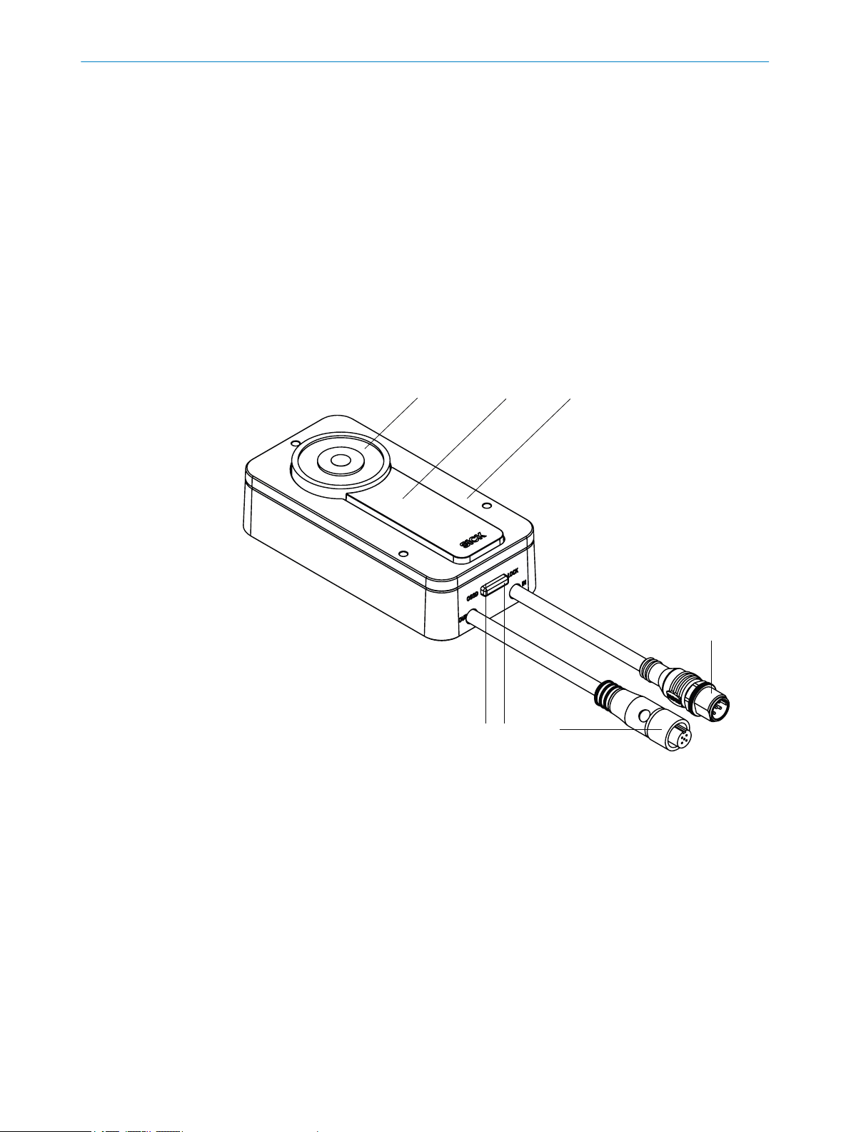
3 Product description
1
2 3
4
5
6
7
3.1 Structure and function
The safety switch is an interlocking device with a locking device consisting of a non-con‐
act sensor with locking solenoid and a coded actuator. The actuator has a low coding
t
level.
If the protective device is closed, the actuator is led to the sensor. If the actuation field
is reached, the actuator code is read out and evaluated by RFID. If the code is valid, the
safe output signal switching device (OSSD) switches.
If the locking solenoid is supplied with power, the locking device is active.
3.2 Product characteristics
3.2.1 Device overview
PRODUCT DESCRIPTION 3
Figure 1: Sensor
Locking solenoid
1
Sensor surface
2
Cover plate
3
Plug connector IN
4
Plug connector OUT
5
LOCK light emitting diode
6
OSSD light emitting diode
7
8020169/ZJN1/2018-03-21 | SICK OP E RA T IN G I N ST R UC T IO N S | MLP1
Subject to change without notice
9
Page 10
1 2 3
3 P
RODUCT DESCRIPTION
Figure 2: Actuator
1
2
3
3.2.2 Product variants
The safety switch is delivered in different variants. You will find an overview of impor‐
t
ant distinguishing features of the variants in the following.
Anchor plate
Protective cap
Actuator surface
•
•
•
3.2.3 Locking principle
Important information
DANGER
azard due to lack of effectiveness of the protective device
H
In the event of a voltage drop, the locking device unlocks regardless of whether the
dangerous state of the machine has ended
b
Power to lock principle
•
•
If voltage is interrupted, the locking device is unlocked and the protective device can be
opened immediately.
Complementary information
•
•
•
2 cables with M12 plug connector (5-pin)
1 cable with M12 plug connector (5-pin)
1 cable with M12 plug connector (8-pin)
Do not use the safety switch in applications in which the dangerous state cannot
be ended immediately (stopping/run-down time).
ock locking device: voltage at locking device input
L
Unlock locking function: no voltage at locking device input
T
he locking device is not monitored, which means that the safety switch does not
check whether the anchor plate is applied to the solenoid.
The locking force is not monitored.
Locking force is not a safety-related function.
3.2.4 Protective functions
The safety switch has the following internal protective functions:
•
•
10
O PE R AT I NG IN S TR U CT I ON S | MLP1 8020169/ZJN1/2018-03-21 | SICK
hort-circuit protection at all outputs
S
Cross-circuit monitoring at OSSDs
Subject to change without notice
Page 11
•
2 1
•
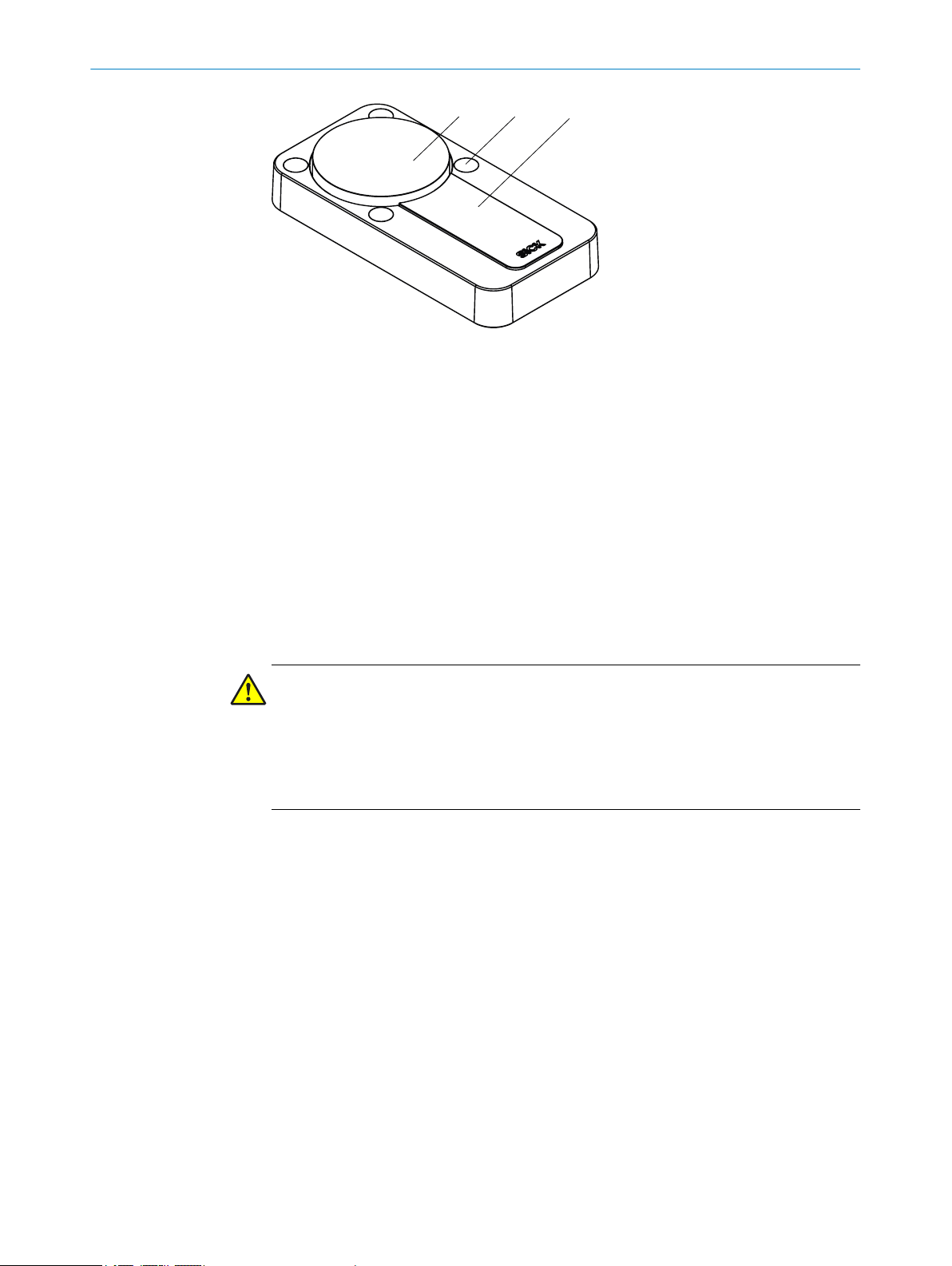
3.2.5 Status indicators
The safety switch outputs important status information using a number of LEDs.
verload protection on OSSDs
O
Supply voltage reverse polarity protection
PRODUCT DESCRIPTION 3
Figure 3: Status LEDs
able 1: Status LEDs
T
No. Name Color Meaning
1
2
1)
When a too high load is applied to the application diagnostic output, the red OSSD LED remains continu‐
ousl
y lit. This will not have any effect on the actual switching behavior of the safety switch.
LOCK Yellow Lights up when the
gnet is supplied
ma
with voltage.
OSSD Red/green Lights up green when
he OSSD pair is in the
t
ON state.
Lights up red when
the OSSD pair is in the
OFF state.
1)
8020169/ZJN1/2018-03-21 | SICK OP E RA T IN G I N ST R UC T IO N S | MLP1
Subject to change without notice
11
Page 12

4 PROJECT PLANNING
4 Project planning
4.1 Manufacturer of the machine
DANGER
F
ailure to comply with manufacturer’s obligations
Hazard due to lack of effectiveness of the protective device
Carry out a risk assessment before using the safety switch.
b
Do not tamper with, open, or modify the components of the safety switch.
b
Do not repair defective devices – they must be replaced instead.
b
Make sure that switch-on commands which bring about a dangerous state of the
b
machine are not enabled until the protective device is closed.
Make sure that a stop command is triggered when the protective device is opened
b
during the dangerous machine state.
The safety switches must not be defeated (contacts jumpered), rotated away,
b
removed, or rendered ineffective in any other way. If necessary, put measures in
place to reduce possibilities for defeat.
If several devices are connected in series (cascade) and the simplified process accord‐
g to EN ISO 13849 is used to determine the performance level (PL), the PL may be
in
reduced.
As the number of safety switches in a cascade increases, so too does the response
time.
4.2 Operating entity of the machine
DANGER
ailure to comply with operating entity’s obligations
F
Hazard due to lack of effectiveness of the protective device
Modifications to the machine and modifications to the mechanical mounting of
b
the safety switch necessitate a new risk assessment. The results of this risk
assessment may require the operating entity of the machine to fulfill the manufac‐
turer’s obligations.
Apart from during the procedures described in this document, the components of
b
the safety switch must not be opened or modified.
Do not perform repair work on the components. Improper repair of the safety
b
switch can lead to a loss of the protective function.
Ensure that there is no bypassing by replacement actuators. Restrict access to
b
actuators.
12
O PE R AT I NG IN S TR U CT I ON S | MLP1 8020169/ZJN1/2018-03-21 | SICK
Subject to change without notice
Page 13

4.3 Assembly
PROJECT PLANNING 4
Important information
DANGER
ypassing the protective device
B
Hazard due to lack of effectiveness of the protective device
Avoid incentives to manipulate the safety switch by taking at least one of the fol‐
b
lowing measures:
Cover the sensor and the actuator with additional equipment or protect them
°
against access.
If possible use permanent mounting methods for actuators (e.g., glue, safety
°
screws, or rivets).
Mounting location
S
elect the mounting location so that the sensor and actuator are accessible for
b
maintenance work and are protected against damage.
Select a mounting location that ensures the sensor is as far away from the door
b
hinge as possible.
If necessary, fit an additional stop for the moving protective device.
b
Distance
When several safety switches are mounted to the machine, they must be mounted at a
minimum distance to one another see "Mounting several safety switches", page 20.
Alignment
The safety switch can be mounted in any alignment. When mounted horizontally, manip‐
ulation protection is increased by the anchor plate with rotating bearings. When
mounted horizontally, if the actuator is triggered by the movable physical guard, the
actuator is held by the magnet. As the anchor plate has rotating bearings, the gravita‐
tional force rotates the actuator surface away from the sensor surface and the OSSDs
go into the OFF state.
2 possible mounting methods
The sensor can be mounted in 2 ways:
Surface mounting. The sensor is mounted on the fixed part of the protective
•
device (e.g., door frame).
Flush mounting. The sensor is mounted in the fixed part of the protective device
•
(e.g., door frame). There must be a suitable recess in the mounting surface. The
thickness of the mounting surface must be between 1.5 mm and 3 mm.
Complementary information
Dimensional dr
awing of the recess for flush mounting see figure 17.
4.4 Integration into the electrical control
Switch-on commands that put the machine in a dangerous state may only be activated
when t
he protective device is closed. When the machine goes into a dangerous state, a
stop command must be triggered if the protective device is opened. Depending on the
safety concept, the signal is analyzed by safety relays or a safety controller, for example.
8020169/ZJN1/2018-03-21 | SICK OP E RA T IN G I N ST R UC T IO N S | MLP1
Subject to change without notice
13
Page 14
ROJECT PLANNING
4 P
4.4.1 OSSDs
The control that is connected and all devices responsible for safety must comply with
t
he required performance level and the required category (for example, according to
ISO 13849-1).
Safety switches with local inputs and outputs can be directly integrated into the
mac
hine controller.
DANGER
H
azard due to lack of effectiveness of the protective device
In the case of non-compliance, it is possible that the dangerous state of the machine
may not be stopped or not stopped in a timely manner.
Make sure that the following control and electrical requirements are met so the
b
protective function can be fulfilled.
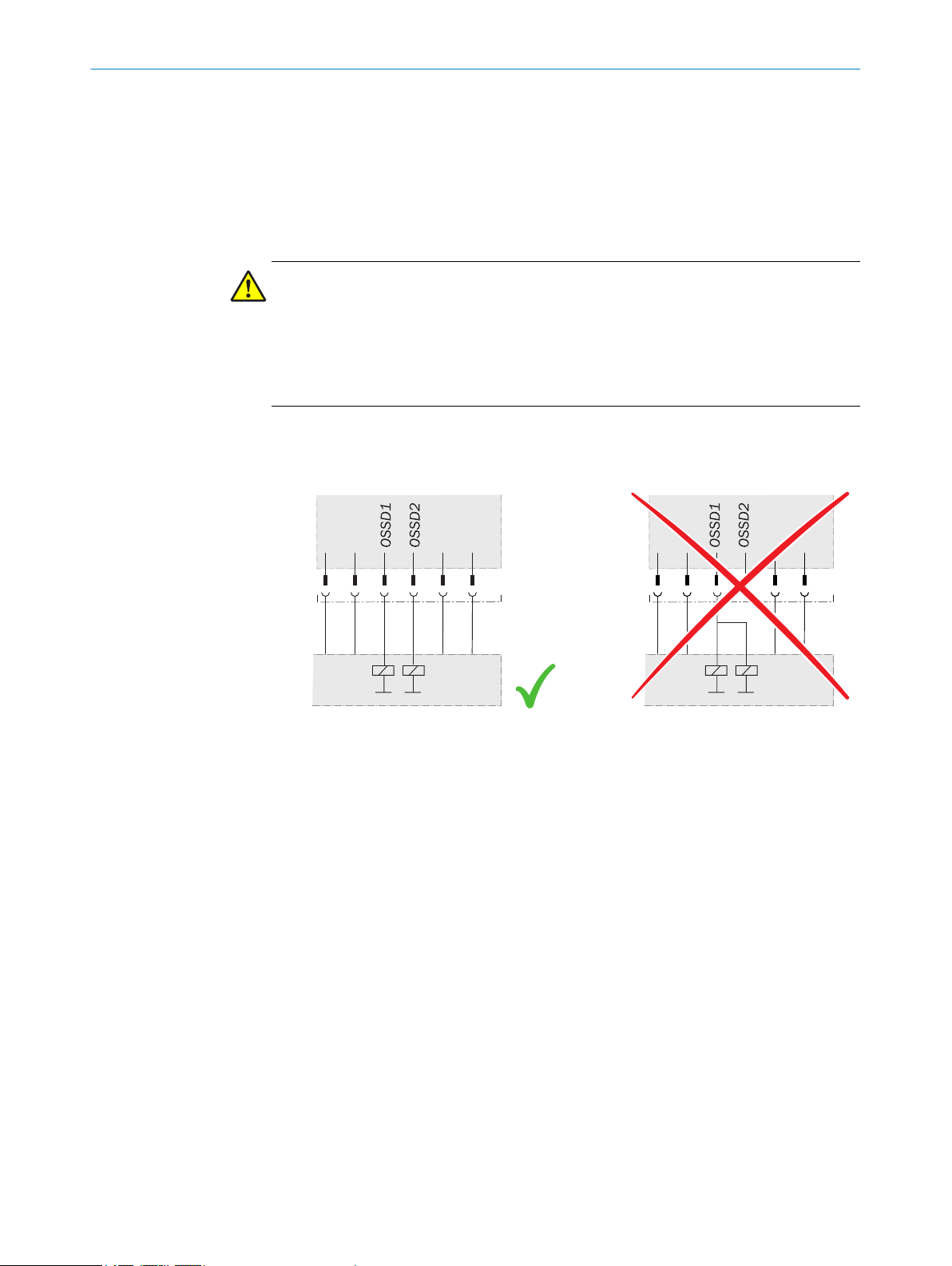
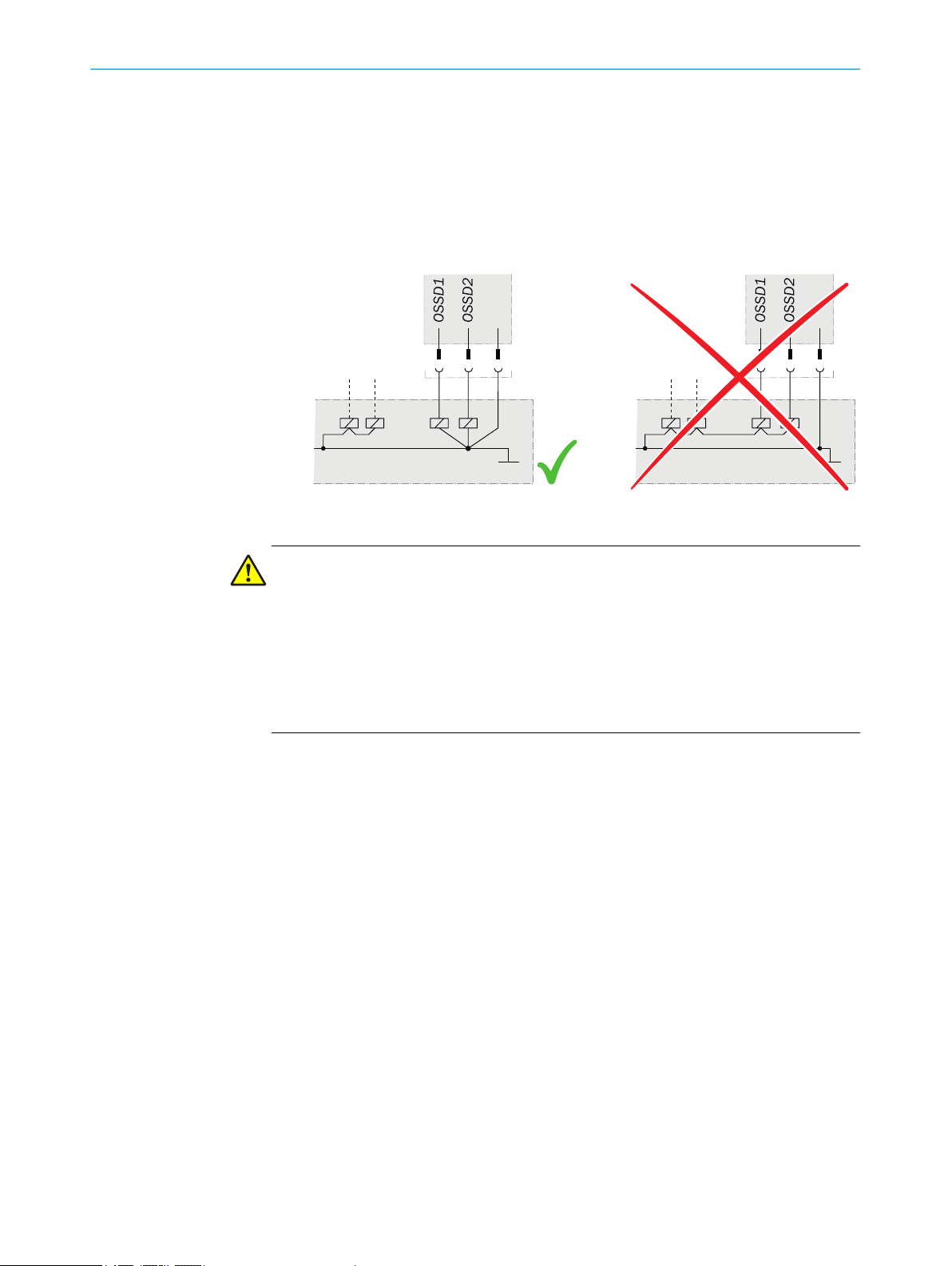
T
he output signals from an OSSD pair must not be connected to each other.
•
In the machine controller, both signals from an OSSD pair must be processed sep‐
•
arately.
Figure 4: Dual-channel and isolated connection of OSSD 1 and OSSD 2
he machine must switch to the safe state at any time if at least one OSSD in an
T
•
OSSD pair switches to the OFF state.
14
O PE R AT I NG IN S TR U CT I ON S | MLP1 8020169/ZJN1/2018-03-21 | SICK
Subject to change without notice
Page 15
PROJECT PLANNING 4
event the formation of a potential difference between the load and the protec‐
Pr
•
tive device. If you connect loads to the OSSDs (safety outputs) that then also
switch if controlled with negative voltage (e.g., electro-mechanical contactor with‐
out reverse polarity protection diode), you must connect the 0 V connections of
these loads and those of the corresponding protective device individually and
directly to the same 0 V terminal strip. In the event of a fault, this is the only way to
ensure that there can be no potential difference between the 0 V connections of
the loads and those of the corresponding protective device.
Figure 5: No potential difference between load and protective device
DANGER
azard due to lack of effectiveness of the protective device
H
In the case of non-compliance, it is possible that the dangerous state of the machine
may not be stopped or not stopped in a timely manner.
Downstream contactors must be positively guided and monitored depending on applic‐
able national regulations or required reliability of the safety function.
Make sure that downstream contactors are monitored (external device monitoring,
b
EDM).
Requirements for the electrical control of the machine
Use t
•
•
he control without test pulses. The safety switch is self-testing.
The safety switch tests the OSSDs at regular intervals. To do this, it switches each
OSSD briefly (for max. 1 ms) to the OFF state and checks whether this channel is
voltage-free during this time.
Make sure that the machine’s control does not react to these test pulses and the
machine does not switch off.
T
he inputs of a connected evaluation unit must be positive-switching (PNP), as the
•
two outputs of the safety switch send a level of the supply voltage in the switchedon state.
The OSSDs are short-circuit protected to 24 V DC and 0 V. When the actuator is in the
sensor’s response range, the OSSDs signal the ON state with the HIGH signal level (nonisolated). If the actuator is removed from the sensor’s response range or there is a
device fault, the OSSDs signal the OFF state with the LOW signal level.
The safety switch complies with the regulations for electromagnetic compatibility (EMC)
for the industrial sector (Radio Safety Class A). Radio interference cannot be ruled out
when used in residential areas.
8020169/ZJN1/2018-03-21 | SICK OP E RA T IN G I N ST R UC T IO N S | MLP1
Subject to change without notice
15
Page 16

OSSD 1
V
t
1
OSSD 2
V
t
300 µs
300 µs
4 PROJECT PLANNING
DANGER
azard due to lack of effectiveness of the protective device
H
In the case of non-compliance, it is possible that the dangerous state of the machine
may not be stopped or not stopped in a timely manner.
Make sure that the following control and electrical requirements are met so the
b
safety switch can fulfill its protective function.
he external voltage supply of the safety switch must be capable of jumpering brief
T
•
power failures of 20 ms as specified in IEC 60204-1.
The power supply unit must provide safe isolation according to IEC 61140 (SELV/
•
PELV). Suitable power supply units are available as accessories from SICK.
4.4.2 Course of the OSSD test over time
Figure 6: Course of the OSSD test over time
Usually every 40 ms.
1
he interval is dynamic and can be smaller than 40 ms.
T
4.4.3 Controlling the locking solenoid
The locking solenoid is activated through the upstream control. There is no internal acti‐
v
ation or deactivation of the locking solenoid through the safety switch. The locking
device and locking force are not monitored. When the machine starts, the following
sequence must be followed:
1 Check whether safety switch OSSDs are in the ON state.
2 Supply the locking solenoid with power.
3 Start the machine.
4.4.4 Application diagnostic output
Switching behavior of the application diagnostic output
T
he application diagnostic output signal changes as soon as the actuator is moved into
or out of the response range of the safety switch. That is, when the movable protective
device is opened or closed. This is not a safety output.
16
O PE R AT I NG IN S TR U CT I ON S | MLP1 8020169/ZJN1/2018-03-21 | SICK
Table 2: Switching behavior of the application diagnostic output
Actuator Application diagnostic output
Actuator not in the response area, or safety
witch in an error state
s
Actuator in the response area ON
OFF
Subject to change without notice
Page 17

4.4.5 Cascading
PROJECT PLANNING 4
Further topics
"T
echnical data", page 34
•
Several safety switches can be connected using cascading. The connected devices act
lik
e one device.
Structure of a cascade
A cascade can be structured as follows:
Connecting the safety switches with M12 plug connectors, terminating the cas‐
•
cade with an end connector (only for variant with 2 M12 plug connectors)
Connecting the safety switches with special T-connectors, terminating the cascade
•
with an end connector (only for variant with 8-pin M12 plug connector)
DANGER
ypassing the protective device
B
The dangerous state may not be stopped in the event of non-compliance.
1. If a cascade is created with directly connected safety switches, the connecting
cable must be mounted so that a safety switch cannot be easily jumpered; e.g.,
cover plug connector or protect against access with additional means (e.g., protec‐
tive cover with disposable screws).
2. If a cascade is created with T-connectors, the connecting cable must be mounted
so that individual T-connectors (and therefore a safety switch) cannot be easily
jumpered.
Both connection methods can be combined as desired.
8020169/ZJN1/2018-03-21 | SICK OP E RA T IN G I N ST R UC T IO N S | MLP1
Subject to change without notice
17
Page 18

8
2
3
4
5
7
1
6
ROJECT PLANNING
4 P
Using other safety switches
NOTE
ascade, other safety switches within the cascade can also be used via special T-
In a c
connectors as long as the connections are structured as follows:
Table 3: Device connection pin assignment (male connector, M12, 8-pin, A-coded)
Pin Wire color
1 White – –
2 Brown +24 V DC Safety switch voltage supply
3 Green N. c.
1)
Designation Description
2)
Not connected
or
+24 V DC
or
oltage supply for locking device
V
3)
4 Yellow In 2 OSSD 2 input
5 Gray OSSD 1 OSSD 1 output
6 Pink OSSD 2 OSSD 2 output
7 Blue 0 V 0 V DC voltage supply
8 Red In 1 OSSD 1 input
1)
Applies to the extension cables recommended as accessories.
2)
Pin 1 is not assigned on T-connector. Safety switch signals to pin 1 are not relevant for the cascade (see
figure 18).
3)
The locking device must function in accordance with the power to lock principle.
Additional voltage supply
T
he voltage drop in the cascade must be checked so that the defined minimum voltage
is still applied to each safety switch. If the defined minimum voltage is no longer
applied to a safety switch, a node for voltage supply must be integrated. The node for
voltage supply must be integrated in the direction of the safe evaluation unit, as close
as possible to the relevant switch in the cascade.
Number of safety switches
The maximum number of safety switches depends on the following factors:
Applied supply voltage
•
Length of cables used
•
Cable cross-section of cables used
•
Load current
•
Nodes for voltage supply
•
Required performance level (see "Technical data", page 34)
•
The number of safety switches in a cascade influences the response time of the system
(see "Technical data", page 34).
The maximum number of safety switches in a cascade changes depending on the total
length of cable as follows:
18
O PE R AT I NG IN S TR U CT I ON S | MLP1 8020169/ZJN1/2018-03-21 | SICK
Subject to change without notice
Page 19

Table 4: Maximum number of cascadable safety switches in relation to the total length of the cas‐
c
ade
Maximum number of cascadable safety
s
witches
1 140 m
2 70 m
3 46 m
4 35 m
5 28 m
6 22 m
7 20 m
1)
At a cable cross-section of 0.34 mm²
If a cascade has more safety switches or gets longer, additional voltage must be fed in
v
ia a node for voltage supply.
4.5 Thorough check concept
The safety switch must be tested by appropriately qualified safety personnel during
commis
page 30.
sioning, after modifications, and at regular intervals; see "Thorough check",
PROJECT PLANNING 4
Total length of the cascade
1)
Regular thorough checks serve to investigate the effectiveness of the safety switch and
discover defects resulting from modifications or external influences (such as damage or
manipulation).
The manufacturer and operating entity must define the type and frequency of the thor‐
ough checks on the machine on the basis of the application conditions and the risk
assessment. The process of defining the thorough checks must be documented in a
traceable manner.
4.5.1 Minimum requirements for the regular thorough check
The following thorough checks must be carried out at least once a year:
T
horough check of the protective function of the safety switch
•
Thorough check of the switch housing for damage
•
Thorough check of the switch cables for damage
•
Thorough check of the safety switch for signs of misuse or manipulation
•
Thorough check of the locking solenoid for correct function
•
8020169/ZJN1/2018-03-21 | SICK OP E RA T IN G I N ST R UC T IO N S | MLP1
Subject to change without notice
19
Page 20

260mm
260mm
5 MOUN
TING
5 Mounting
5.1 Mounting several safety switches
When several safety switches are mounted, the prescribed minimum distance
b
between the individual systems must be adhered to in order to avoid mutual inter‐
ference.
5.2 Mounting
2 possible mounting methods
T
he sensor can be mounted in 2 ways:
Surface mounting. The sensor is mounted on the fixed part of the protective
•
device (e.g., door frame).
Flush mounting. The sensor is mounted in the fixed part of the protective device
•
(e.g., door frame). There must be a suitable recess in the mounting surface. The
thickness of the mounting surface must be between 1.5 mm and 3 mm.
Dimensional drawing of the recess for flush mounting see
NOTE
talling the safety switch horizontally increases protection against manipulation.
Ins
Mounting the sensor
1.
Unscrew the fixing screw (hexagon socket, 2 mm) and remove the cover plate:
figure 17.
20
O PE R AT I NG IN S TR U CT I ON S | MLP1 8020169/ZJN1/2018-03-21 | SICK
Subject to change without notice
Page 21

MOUNTING 5
Figure 7: Removing the cover plate
2. Mount the sensor on the fixed part of the protective device with 4 x M4 screws and
sec
ure it with 4 nuts.
With surface mounting: mount the sensor on the fixed part of the protective
°
device. The screws can be set in the front or the back:
Figure 8: Surface mounting
8020169/ZJN1/2018-03-21 | SICK OP E RA T IN G I N ST R UC T IO N S | MLP1
Subject to change without notice
21
Page 22

≤3°
5 MOUN
TING
ith surface mounting: mount the sensor in the fixed part of the protective
W
°
device:
Figure 9: Flush mounting
Tightening torque: 1 Nm.
3. Set cover plate on the sensor.
4.
Tighten the fixing screws. Tightening torque: 0.8 Nm.
Mounting the actuator
1. Align the actuator to the mounted sensor.
2. Mount the actuator on the moving part of the protective device (e.g., door) with 4 x
M4 screws. Tightening torque: 1 Nm. Use disposable screws if possible.
Maximum deviation between sensor and actuator: 5 mm.
°
Maximum angle between sensor and actuator when protective device is
°
closed: 3°
Figure 10: Maximum angle between sensor and actuator
3. Cover drill holes of the actuator with protective caps.
22
O PE R AT I NG IN S TR U CT I ON S | MLP1 8020169/ZJN1/2018-03-21 | SICK
Subject to change without notice
Page 23

6 Electrical installation
12
3
4
5
12
3
4
5
6.1 Notes on cULus
For use according to the requirements of UL 508, the following conditions must also be
t:
me
Voltage supply Uv sensor secured with 2 A fuse
•
Voltage supply Uv magnet secured with 2 A fuse
•
6.2 Device connection (M12, 5-pin)
Device connection (male connector, M12, 5-pin, A-coded)
Table 5: Device connection pin assignment (male connector, M12, 5-pin, A-coded)
Pin Wire color
1 Brown +24 V DC Safety switch voltage supply
2 White OSSD 1 OSSD 1 output
3 Blue 0 V 0 V DC voltage supply
4 Black OSSD 2 OSSD 2 output
5 Gray Magnet Magnet activation 24 V DC
1)
Applies to the extension cables recommended as accessories.
1)
ELECTRICAL INSTALLATION 6
Designation Description
P
ay attention to tightness of the plug connector.
b
6.3 Device connection (2 x M12, 5-pin)
IN device connection (male connector, M12, 5-pin, A-coded)
Table 6: IN device connection pin assignment (male connector, M12, 5-pin, A-coded)
Pin Wire color
1 Brown In +24 V DC Safety switch voltage supply
2 White OSSD 1 OSSD 1 output
3 Blue 0 V 0 V DC voltage supply
4 Black OSSD 2 OSSD 2 output
5 Gray Magnet Input for magnet activation
1)
Applies to the extension cables recommended as accessories.
1)
Designation Description
24 V DC
8020169/ZJN1/2018-03-21 | SICK OP E RA T IN G I N ST R UC T IO N S | MLP1
Subject to change without notice
23
Page 24

21
4
3
5
8
2
3
4
5
7
1
6
6 ELE
CTRICAL INSTALLATION
OUT device connection (female connector, M12, 5-pin, A-coded)
Table 7: OUT device connection pin assignment (female connector, M12, 5-pin, A-coded)
Pin Wire color
1 Brown Out +24 V DC Safety switch voltage supply
2 White In 1 OSSD 1 input
3 Blue 0 V 0 V DC voltage supply
4 Black In 2 OSSD 2 input
5 Gray Magnet Output for magnet activation
1)
Applies to the extension cables recommended as accessories.
P
ay attention to tightness of the plug connectors.
b
1)
Designation Description
24 V DC
6.4 Device connection (M12, 8-pin)
Device connection (male connector, M12, 8-pin, A-coded)
Table 8: Device connection pin assignment (male connector, M12, 8-pin, A-coded)
Pin Wire color
1 White Aux Application diagnostic output
2 Brown +24 V DC Safety switch voltage supply
3 Green Magnet Magnet activation 24 V DC
4 Yellow In 2 OSSD 2 input
5 Gray OSSD 1 OSSD 1 output
6 Pink OSSD 2 OSSD 2 output
7 Blue 0 V 0 V DC voltage supply
8 Red In 1 OSSD input 1
1)
Applies to the extension cables recommended as accessories.
2)
When used as an individual safety switch or as the first safety switch in a cascade: Apply 24 V DC.
1)
Designation Description
t safe)
(no
2)
2)
P
ay attention to tightness of the plug connector.
b
6.5 Connecting a cascade
A safety switch cascade can be created in different ways. Depending on the structure,
end connectors, T-connectors, and nodes are required for voltage supply (see "Acces‐
sories", page 41).
24
O PE R AT I NG IN S TR U CT I ON S | MLP1 8020169/ZJN1/2018-03-21 | SICK
Subject to change without notice
Page 25

Connecting directly connected safety switches
21 3 3
5 5
4
5
Figure 11: Cascading several safety switches
Safe evaluation unit
1
Connecting cable, M12, 5-pin
2
Connection cable, M12, 5-pin
3
End connector
4
MLP1 safety switch (2 × M12, 5-pin)
5
ELECTRICAL INSTALLATION 6
DANGER
B
The dangerous state may not be stopped in the event of non-compliance.
b
ypassing the protective device
If a cascade is created with directly connected safety switches, connecting cables
must be mounted so that a safety switch cannot be easily jumpered; e.g., cover
plug connectors or protect against access with additional means (e.g., protective
cover with disposable screws)
8020169/ZJN1/2018-03-21 | SICK OP E RA T IN G I N ST R UC T IO N S | MLP1
Subject to change without notice
25
Page 26

33
7 7 7
4
2
6 6 6
1
5 5 5
6 ELECTRICAL INSTALLATION
Connecting safety switches connected with T-connectors
Safe evaluation unit
1
Connecting cable, M12, 5-pin
2
Connection cable, M12, 5-pin
3
End connector
4
MLP1 safety switch (M12, 8-pin)
5
T-connector
6
Connection cable, M12, 8-pin
7
DANGER
ypassing the protective device
B
The dangerous state may not be stopped in the event of non-compliance.
If the cascade is created using T-pieces, install the connecting cables in a way that pre‐
vents a single T-piece (and therefore a safety switch) from simply being jumpered.
26
O PE R AT I NG IN S TR U CT I ON S | MLP1 8020169/ZJN1/2018-03-21 | SICK
Subject to change without notice
Page 27

Connecting an additional voltage supply
21 3 33 6
4
555
2
8
33
7 7 7
4
2
6 6 6
1
5 5
ELECTRICAL INSTALLATION 6
Safe evaluation unit
1
Connecting cable, M12, 5-pin
2
Connection cable, M12, 5-pin
3
End connector
4
MLP1 safety switch (2 × M12, 5-pin)
5
Nodes for voltage supply
6
Connecting other safety switches
Figure 12: Cascading several safety switches
Safe evaluation unit
1
Connecting cable, M12, 5-pin
2
8020169/ZJN1/2018-03-21 | SICK OP E RA T IN G I N ST R UC T IO N S | MLP1
Subject to change without notice
27
Page 28

8
2
3
4
5
7
1
6
6 ELE
CTRICAL INSTALLATION
Connection cable, M12, 5-pin
3
End connector
4
MLP1 safety switch (M12, 8-pin)
5
T-connector
6
Connection cable, M12, 8-pin
7
Other safety switch, M12, 8-pin
8
NOTE
ascade, other safety switches within the cascade can also be used via special T-
In a c
connectors as long as the connections are structured as follows:
Table 9: Device connection pin assignment (male connector, M12, 8-pin, A-coded)
Pin Wire color
1 White – –
2 Brown +24 V DC Safety switch voltage supply
3 Green N. c.
1)
Designation Description
2)
Not connected
or
+24 V DC
or
oltage supply for locking device
V
3)
4 Yellow In 2 OSSD 2 input
5 Gray OSSD 1 OSSD 1 output
6 Pink OSSD 2 OSSD 2 output
7 Blue 0 V 0 V DC voltage supply
8 Red In 1 OSSD 1 input
1)
Applies to the extension cables recommended as accessories.
2)
Pin 1 is not assigned on T-connector. Safety switch signals to pin 1 are not relevant for the cascade (see
figure 18).
3)
The locking device must function in accordance with the power to lock principle.
Combining connection methods as desired
T
he various connection methods can be combined within a cascade as desired.
28
O PE R AT I NG IN S TR U CT I ON S | MLP1 8020169/ZJN1/2018-03-21 | SICK
Subject to change without notice
Page 29

21
3
9
2
4
5
5
8
7
8
7
6 6
33 3
Safe evaluation unit
12
3
4
5
1
Connecting cable, M12, 5-pin
2
Connection cable, M12, 5-pin
3
End connector
4
MLP1 safety switch
5
T-connector
6
Connection cable, M12, 8-pin
7
Other safety switch, M12, 8-pin
8
Nodes for voltage supply
9
ELECTRICAL INSTALLATION 6
Cascade connection (M12, 5-pin)
T
he 5-pin male connector of the last safety switch or T-connector upstream of the safe
evaluation unit is the interface between the cascade and the safe evaluation unit.
Figure 13: Cascade connection (M12, 5-pin, A-coded, male connector)
able 10: Device connection pin assignment (male connector, M12, 5-pin, A-coded)
T
Pin Wire color
1 Brown In +24 V DC Safety switch voltage supply
2 White OSSD 1 OSSD 1 output
3 Blue 0 V 0 V DC voltage supply
4 Black OSSD 2 OSSD 2 output
5 Gray In +24 V DC Locking solenoid voltage supply
1)
Applies to the extension cables recommended as accessories.
1)
Designation Description
8020169/ZJN1/2018-03-21 | SICK OP E RA T IN G I N ST R UC T IO N S | MLP1
Subject to change without notice
29
Page 30

7 C
OMMISSIONING
7 Commissioning
7.1 Safety
DANGER
H
azard due to lack of effectiveness of the protective device
In the case of non-compliance, it is possible that the dangerous state of the machine
may not be stopped or not stopped in a timely manner.
1. Before commissioning the machine, have it checked and released by qualified
safety personnel.
2. Make sure that the time for the safety requirement (closing the protective device
again) is longer than the response time.
7.2 Switching on
The device initializes after it is switched on. OSSDs are switched off in the meantime.
The OSSD light emitting diode lights up after initialization.
7.3 Thorough check
Requirements for the thorough check during commissioning and in certain situations
T
he protective device and its application must be thoroughly checked in the following
situations:
Before commissioning
•
After changes to the configuration or the safety function
•
After changes to the mounting, the alignment, or the electrical connection
•
After exceptional events, such as after a manipulation has been detected, after
•
modification of the machine, or after replacing components
The thorough check ensures the following:
All relevant regulations are complied with and the protective device is active for all
•
of the machine’s operating modes.
The documentation corresponds to the state of the machine, including the protec‐
•
tive device
The thorough checks must be carried out by qualified safety personnel or specially qual‐
ified and authorized personnel and must be documented in a traceable manner.
k whether the protective device of the machine is effective in all operating
Chec
b
modes in which the machine can be set.
Make sure that operating personnel have been instructed in the function of the
b
protective device before starting work on the machine. The machine operator has
overall responsibility for the instruction, which must be carried out by qualified per‐
sonnel.
30
O PE R AT I NG IN S TR U CT I ON S | MLP1 8020169/ZJN1/2018-03-21 | SICK
Subject to change without notice
Page 31

8 Troubleshooting
8.1 Safety
DANGER
H
azard due to lack of effectiveness of the protective device
In the case of non-compliance, it is possible that the dangerous state of the machine
may not be stopped or not stopped in a timely manner.
Immediately shut the machine down if the behavior of the machine cannot be
b
clearly identified.
If a machine fault cannot be definitively determined or safely rectified, immediately
b
shut the machine down.
Secure the machine so that it cannot switch on unintentionally.
b
DANGER
H
azard due to unexpected starting of the machine
When any work is taking place, use the protective device to secure the machine or
b
to ensure that the machine is not switched on unintentionally.
TROUBLESHOOTING 8
DANGER
azard due to lack of effectiveness of the protective device
H
In the case of non-compliance, it is possible that the dangerous state of the machine
may not be stopped or not stopped in a timely manner.
b
b
b
NOTE
ou cannot remedy the fault with the help of the information provided in this chapter,
If y
please contact your respective SICK subsidiary.
8.2 Troubleshooting
Perform one of the following steps in the event of an error:
b
b
b
b
Do not carry out any repairs on the device components.
Do not modify or manipulate device components.
Apart from during the procedures described in this document, the device compo‐
nents must not be opened.
k voltage supply.
Chec
Check cables.
Check alignment of safety switch and actuator.
Check ambient conditions (e.g., interfering RFID frequencies or magnetic fields,
distances to other safety switches).
NOTE
afety switch has a fault in a cascade with an end connector, the OSSDs of all
If a s
safety switches between the safe evaluation unit and the safety switch concerned
switch into the OFF state.
8020169/ZJN1/2018-03-21 | SICK OP E RA T IN G I N ST R UC T IO N S | MLP1
Subject to change without notice
31
Page 32

9 MAINTENANCE
9 Maintenance
9.1 Cleaning
NOTICE
D
o not use aggressive cleaning agents (such as isopropanol or spirit).
b
Do not use any substances that hinder the wetting properties of lacquers.
b
We recommend anti-static cleaning agents.
b
9.2 Regular thorough check
The safety switch must be checked regularly. The type and frequency of thorough
hecks is defined by the manufacturer and the operating entity of the machine, see
c
"Thorough check concept", page 19
The regular thorough checks serve to investigate the effectiveness of the safety switch
and detect any ineffectiveness due to modifications or external influences (e.g., dam‐
age or manipulation).
1. Carry out the thorough checks according to the instructions from the manufacturer
and t
he machine user.
32
O PE R AT I NG IN S TR U CT I ON S | MLP1 8020169/ZJN1/2018-03-21 | SICK
Subject to change without notice
Page 33

10 Decommissioning
10.1 Protection of the environment
The safety switch has been designed to minimize its impact on the environment. It uses
gy and resources.
10.2 Disposal
a minimum of ener
Always act in an environmentally responsible manner at work. For this reason,
b
please note the following information regarding disposal.
Always dispose of serviceableness devices in compliance with local/national rules and
egulations with respect to waste disposal.
r
NOTE
We will be glad to help you dispose of these devices on request.
DECOMMISSIONING 10
8020169/ZJN1/2018-03-21 | SICK OP E RA T IN G I N ST R UC T IO N S | MLP1
Subject to change without notice
33
Page 34

11 TECHNICAL DATA
11 Technical data
11.1 Technical data
Table 11: Features
Features
Safe switch on distance S
Typical switch on distance S
Safe switch off distance S
Max. actuation frequency 0.5 Hz
Locking force 500 N
Magnetic retaining force when not supplied
ith power
w
Alignment tolerance for locking device
Vertical 5 mm
Horizontal 5 mm
Aperture angle 3°
ao
o
ar
4 mm
15 mm
45 mm
25 N
Table 12: Safety-related parameters
Safety-related parameters
Performance level PL e (ISO 13849-1)
1)
Category 4 (ISO 13849)
Safety integrity level SIL 3 (EN 61508)
SIL claim limit SILCL 3 (EN 62061)
PFHd (mean probability of a dangerous failure
per hour)
1.5 × 10⁻⁸ a
level
t 40 °C and 1,000 m above seal
TM (mission time) 20 years (ISO 13849-1)
Type Type 4 (ISO 14119)
Coding level Low coding level (ISO 14119)
Safe state when a fault occurs At least one OSSD is in the OFF state
1)
In a cascade, the performance level for the cascade as a whole depends on the number and type of
vices in the cascade. PL e is only possible in cascades with a maximum of 6 devices.
de
Table 13: Interfaces of variant with 1 × M12 plug connector, 5-pin
Interfaces of variant with 1 × M12 plug connector, 5-pin
System connection
Voltage supply
ocal inputs and outputs
L
Male connector, M12, 5-pin, A-coded (common
plug connector for voltage supply and outputs)
Length of connecting cable 150 mm
34
Table 14: Interfaces of variant with 2 × M12 plug connector, 5-pin
Interfaces of variant with 2 × M12 plug connector, 5-pin
System connection
Voltage supply
Local inputs and outputs
Male connector, M12, 5-pin, A-coded (common
plug connector for voltage supply and outputs)
Female connector, M12, 5-pin, A-coded (com‐
mon plug connector for voltage supply and
inputs)
Length of connecting cable 150 mm
O PE R AT I NG IN S TR U CT I ON S | MLP1 8020169/ZJN1/2018-03-21 | SICK
Subject to change without notice
Page 35

TECHNICAL DATA 11
Table 15: Interfaces of variant with 1 × M12 plug connector, 8-pin
Interfaces of variant with 1 × M12 plug connector, 8-pin
System connection
Voltage supply
L
ocal inputs and outputs
Length of connecting cable 150 mm
Table 16: Electrical data
Electrical data
OSSD pairs 1
Rated impulse withstand voltage U
p
im
Pollution degree 3 (external, according to EN 60947-1)
Power-up delay (after supply voltage applied) 1)2.5 s
Supply voltage when an individual safety switch is connected
Supply voltage Vv sensor 24 V DC (19.2 V ... 28.8 V)
Supply voltage Vv ma
gnet 24 V DC (19.2 V ... 28.8 V)
Supply voltage when an cascade is connected
Supply voltage Vv sensor 24 V DC (22.8 V ... 28.8 V)
Supply voltage Vv ma
gnet 24 V DC (21.6 V ... 28.8 V)
Muting time when supply voltage is interrupted 4 ms
Rated insulation voltage Ui 32 V DC
Cable capacitance 400 nF (for Out A and Out B)
Device fuse 0.6 ... 1 A
Current consumption at 24 V
Locking device deactivated 50 mA
Locking device active 350 mA
Protection class III (EN 61140/IEC 61140)
Response time
Release time
Risk time
1)
Once the supply voltage has been switched on, the OSSDs are in the OFF state during the time delay
fore availability. The time specified applies to one sensor; in a cascade, 0.1 s must be added per sen‐
be
sor.
2)
Response time for moving the OSSDs into the OFF state when the actuator is removed from the response
ar
ea or when the OSSD input signals go into the OFF state.
3)
In a cascade, the value is multiplied by the number of safety switches in the cascade.
4)
Response time for moving the OSSDs into the ON state when the actuator is detected by the sensor and
he OSSD input signals are in the ON state.
t
5)
The risk time is the time needed to detect internal and external faults. External errors affect the OSSDs
(shor
t-circuit to an OSSD and cross-circuit between the two OSSDs). At least one of the two OSSDs is
safely switched off during the risk time.
2)
4)
5)
Male connector, M12, 8-pin, A-coded (common
plug connector for voltage supply as well as
inputs and outputs)
1,500 V
≤ 50 ms
≤ 100 ms
≤ 100 ms
3)
3)
3)
Table 17: Mechanical data
Dimensions (W x H x D)
Safety switch 120 mm x 60 mm x 38.5 mm
Actuator 120 mm x 60 mm x 20.5 mm
Material
Sensor housing Anodized aluminum
8020169/ZJN1/2018-03-21 | SICK OP E RA T IN G I N ST R UC T IO N S | MLP1
Subject to change without notice
35
Page 36

11 TECHNICAL DATA
Dimensions (W x H x D)
Actuator housing Fiber-glass-reinforced PVC
Anchor plate Nickle-plated steel
Weight
Safety switch 510 g
Actuator 210 g
Table 18: Inputs
Inputs
Rated voltage 24 V DC
Switching current
ON state ≤ 5 mA
OFF state 0 mA
Switching voltage
ON state 19.2 V DC ... 28.8 V DC
OFF state 0 V DC ... 2 V DC
Table 19: Outputs
Outputs
2 OSSDs (Out 1 and Out 2) 2 x PNP, max. 100 mA, short-circuit protected
and o
verload-proof
1 Application diagnostic output (Aux) 25 mA max,1) shor
t-circuit protected (resistive
load)
Switching voltage (all outputs)
ON state 19.2 V DC ... 28.8 V DC
OFF state 0 V DC ... 2 V DC
Switching current (OSSDs)
ON state ≤ 100 mA
OFF state ≤ 500 µA
Test pulse duration (OSSDs) 300 µs
1)
A higher load affects the behavior of the status indicators, see "S
tatus indicators", page 11.
36
Table 20: Ambient data
Ambient data
Enclosure rating IP 67 (IEC 60529)
Ambient operating temperature –20 °C … +55 °C
Storage temperature -25 °C ... +70 °C
Relative humidity 50% at 70 °C (IEC 60947-5-2)
Vibration resistance 1 mm / 10 Hz ... 55 Hz (IEC 60068-2-6)
Shock resistance 30 g, 11 ms (IEC 60068-2-27)
EMC In accordance with IEC 61326-3-1, IEC
60947-5-2, IE
C 60947-5-3, and EN 300330
V2.1.1
Minimum distance between 2 safety switches Depending on alignment, see "Mounting sev‐
eral safety switches", page 20
O PE R AT I NG IN S TR U CT I ON S | MLP1 8020169/ZJN1/2018-03-21 | SICK
Subject to change without notice
Page 37

11.2 Dimensional drawings
12242
120150
44
Ø 14,5
Ø 5,7
25
5,5
6,5
8
14
24
34
44
60
4,5
10
12242
120150
44
Ø 14,5
Ø 5,7
5,5
6,5
8
14
24
34
44
60
10
4,5
Sensor
Figure 14: Dimensional drawing of MLP1 sensor with 2 × M12 male connector
TECHNICAL DATA 11
Figure 15: Dimensional drawing of MLP1 sensor with 1 × M12 male connector
8020169/ZJN1/2018-03-21 | SICK OP E RA T IN G I N ST R UC T IO N S | MLP1
Subject to change without notice
37
Page 38

120
44
10
8 6
16,8
20,5
17,8
3,7
8
4,5
44
60
44
22
83,5
44
32
22
14,4
15,2
28
14,4
16,3
4 x Ø 5
Ø 42
11 TECHNICAL DATA
Actuator
Figure 16: Dimensional drawing of MLP1 actuator
Dimensional drawing for flush mounting
38
Figure 17: Dimensional drawing for flush mounting
O PE R AT I NG IN S TR U CT I ON S | MLP1 8020169/ZJN1/2018-03-21 | SICK
Subject to change without notice
Page 39

12 Ordering information
12.1 Scope of delivery
S
afety switch
•
Actuator
•
4 protective caps
•
Safety note
•
Mounting instructions
•
Downloadable operating instructions: www.sick.com
•
12.2 MLP1 ordering information
Table 21: MLP1 ordering information
Sensor connection type Type code Part number
Cable with male connector, M12, 5-pin
Cable with female connector, M12, 5-pin
Cable with male connector, M12, 5-pin MLP1-SMMA0AC 1077943
Cable with male connector, M12, 8-pin MLP1-SMMF0AC 1080321
ORDERING INFORMATION 12
MLP1-SMMC0AC 1077942
8020169/ZJN1/2018-03-21 | SICK OP E RA T IN G I N ST R UC T IO N S | MLP1
Subject to change without notice
39
Page 40

13 SPARE PARTS
13 Spare parts
13.1 Actuator
Table 22: Actuator ordering information
Part Type code Part number
MLP1 actuator MLP1-XA 2092167
40
O PE R AT I NG IN S TR U CT I ON S | MLP1 8020169/ZJN1/2018-03-21 | SICK
Subject to change without notice
Page 41

14 Accessories
14.1 Connectivity
Connecting cable, M12, 5-pin (0.34 mm2)
able 23: Ordering information for M12 connecting cable, 5-pin (0.34 mm2)
T
Part Type code Part number
Female connector, straight, 2 m cable, open
end
Female connector, straight, 5 m cable, open
end
Female connector, straight, 10 m cable, open
end
Female connector, straight, 15 m cable, open
end
Connecting cable, M12, 8-pin (0.25 mm2)
able 24: Ordering information for M12 connecting cable, 8-pin (0.25 mm2)
T
Part Type code Part number
Female connector, straight, 2 m cable, open
end
Female connector, straight, 5 m cable, open
end
Female connector, straight, 10 m cable, open
end
Female connector, straight, 15 m cable, open
end
Female connector, straight, 20 m cable, open
end
Female connector, straight, 30 m cable, open
end
ACCESSORIES 14
1)
YF2A15-020VB5XLEAX 2096239
YF2A15-050VB5XLEAX 2096240
YF2A15-100VB5XLEAX 2096241
YF2A15-150VB5XLEAX 2096242
1)
YF2A18-020UA5XLEAX 2095652
YF2A18-050UA5XLEAX 2095653
YF2A18-100UA5XLEAX 2095654
YF2A18-150UA5XLEAX 2095679
YF2A18-200UA5XLEAX 2095680
YF2A18-300UA5XLEAX 2095681
Connection cable, M12, 5-pin (0,34 mm2)
T
able 25: Ordering information for M12 connection cable, 5-pin (0.34 mm2)
Part Type code Part number
Female connector, straight, 0.6 m cable, male
tor, straight
connec
Female connector, straight, 1 m cable, male
tor, straight
connec
Female connector, straight, 1.5 m cable, male
YF2A15-C60UB5M2A15 2096006
YF2A15-010UB5M2A15 2096007
YF2A15-015UB5M2A15 2096008
connector, straight
Female connector, straight, 2 m cable, male
YF2A15-020UB5M2A15 2096009
connector, straight
Female connector, straight, 5 m cable, male
tor, straight
connec
Female connector, straight, 10 m cable, male
YF2A15-050UB5M2A15 2096010
YF2A15-100UB5M2A15 2096011
connector, straight
Female connector, straight, 15 m cable, male
YF2A15-100UB5M2A15 2096171
connector, straight
Female connector, straight, 20 m cable, male
tor, straight
connec
1)
Ambient oper
8020169/ZJN1/2018-03-21 | SICK OP E RA T IN G I N ST R UC T IO N S | MLP1
Subject to change without notice
ating temperature: Down to −30° C with fixed installation.
YF2A15-200UB5M2A15 2095844
1)
41
Page 42

55
44
33
2
2
1
1
5
6
7
8
4
321
14 A
CCESSORIES
Part Type code Part number
Female connector, straight, 30 m cable, male
connec
tor, straight
YF2A15-300UB5M2A15 2095845
Connection cable, M12, 8-pin (0.25 mm2)
able 26: Ordering information for M12 connection cable, 8-pin (0.25 mm2)
T
Part Type code Part number
Female connector, straight, 0.6 m cable, male
connec
tor, straight
Female connector, straight, 1 m cable, male
tor, straight
connec
Female connector, straight, 1.5 m cable, male
YF2A18-C60UA5M2A18 2096031
YF2A18-010UA5M2A18 2096032
YF2A18-015UA5M2A18 2096012
connector, straight
Female connector, straight, 2 m cable, male
YF2A18-020UA5M2A18 2096033
connector, straight
Female connector, straight, 5 m cable, male
YF2A18-050UA5M2A18 2096034
connector, straight
Female connector, straight, 10 m cable, male
tor, straight
connec
YF2A18-100UA5M2A18 2096035
2)
Distributor
T
able 27: Distributor ordering information
Part Type code Part number
T-connector TR4-AK004C 5325889
Figure 18: Internal circuitry: T-connector for series connection
onnector
End c
Table 28: End connector ordering information
Part Type code Part number
End connector for series connection MLP1-XXT 1078201
2)
42
Ambient oper
O PE R AT I NG IN S TR U CT I ON S | MLP1 8020169/ZJN1/2018-03-21 | SICK
ating temperature: Down to −30° C with fixed installation.
Subject to change without notice
Page 43

5
4
3
2
1
55
44
33
22
1
1
5
4
3
2
1
ACCESSORIES 14
Figure 19: Internal circuitry: end connector for series connection
Node
s for voltage supply
Table 29: Nodes for voltage supply ordering information
Part Type code Part number
Nodes for voltage supply MLP1-XXN 1078202
Figure 20: Internal circuitry: nodes for voltage supply ordering information
8020169/ZJN1/2018-03-21 | SICK OP E RA T IN G I N ST R UC T IO N S | MLP1
Subject to change without notice
43
Page 44

15 ANNE
X
15 Annex
15.1 Compliance with EU directives
EU declaration of conformity (excerpt)
he undersigned, who represents the manufacturer below, hereby declares that the
T
product complies with the regulations of the EU directive(s) below (including all relevant
changes), and that it is based on the relevant standards and/or technical specifica‐
tions.
Complete EU declaration of conformity for download
You can call up the EU declaration of conformity and the current operating instructions
for the protective device by entering the part number in the search field at
www.sick.com (part number: see the type label entry in the “Ident. no.” field).
44
O PE R AT I NG IN S TR U CT I ON S | MLP1 8020169/ZJN1/2018-03-21 | SICK
Subject to change without notice
Page 45

ANNEX 15
8020169/ZJN1/2018-03-21 | SICK OP E RA T IN G I N ST R UC T IO N S | MLP1
Subject to change without notice
45
Page 46

15 ANNEX
46
O PE R AT I NG IN S TR U CT I ON S | MLP1 8020169/ZJN1/2018-03-21 | SICK
Subject to change without notice
Page 47

ANNEX 15
8020169/ZJN1/2018-03-21 | SICK OP E RA T IN G I N ST R UC T IO N S | MLP1
Subject to change without notice
47
Page 48

Further locations at www.sick.com
Australia
Phone +61 3 9457 0600
1800 334 802 – tollfree
E-Mail sales@sick.com.au
Austria
Phone +43 22 36 62 28 8-0
E-Mail office@sick.at
Belgium/Luxembourg
Phone +32 2 466 55 66
E-Mail info@sick.be
Brazil
Phone +55 11 3215-4900
E-Mail marketing@sick.com.br
Canada
Phone +1 905 771 14 44
E-Mail information@sick.com
Czech Republic
Phone +420 2 57 91 18 50
E-Mail sick@sick.cz
Chile
Phone +56 2 2274 7430
E-Mail info@schadler.com
China
Phone +86 20 2882 3600
E-Mail info.china@sick.net.cn
Denmark
Phone +45 45 82 64 00
E-Mail sick@sick.dk
Finland
Phone +358-9-2515 800
E-Mail sick@sick.fi
France
Phone +33 1 64 62 35 00
E-Mail info@sick.fr
Germany
Phone +49 211 5301-301
E-Mail info@sick.de
Hong Kong
Phone +852 2153 6300
E-Mail ghk@sick.com.hk
Hungary
Phone +36 1 371 2680
E-Mail office@sick.hu
India
Phone +91 22 6119 8900
E-Mail info@sick-india.com
Israel
Phone +972 4 6881000
E-Mail info@sick-sensors.com
Italy
Phone +39 02 274341
E-Mail info@sick.it
Japan
Phone +81 3 5309 2112
E-Mail support@sick.jp
Malaysia
Phone +6 03 8080 7425
E-Mail enquiry.my@sick.com
Mexico
Phone +52 (472) 748 9451
E-Mail mario.garcia@sick.com
Netherlands
Phone +31 30 2044 000
E-Mail info@sick.nl
New Zealand
Phone +64 9 415 0459
0800 222 278 – tollfree
E-Mail sales@sick.co.nz
Norway
Phone +47 67 81 50 00
E-Mail sick@sick.no
Poland
Phone +48 22 539 41 00
E-Mail info@sick.pl
Romania
Phone +40 356 171 120
E-Mail office@sick.ro
Russia
Phone +7 495 775 05 30
E-Mail info@sick.ru
Singapore
Phone +65 6744 3732
E-Mail sales.gsg@sick.com
Slovakia
Phone +421 482 901201
E-Mail mail@sick-sk.sk
Slovenia
Phone +386 591 788 49
E-Mail office@sick.si
South Africa
Phone +27 11 472 3733
E-Mail info@sickautomation.co.za
South Korea
Phone +82 2 786 6321
E-Mail info@sickkorea.net
Spain
Phone +34 93 480 31 00
E-Mail info@sick.es
Sweden
Phone +46 10 110 10 00
E-Mail info@sick.se
Switzerland
Phone +41 41 619 29 39
E-Mail contact@sick.ch
Taiwan
Phone +886 2 2375-6288
E-Mail sales@sick.com.tw
Thailand
Phone +66 2645 0009
E-Mail Ronnie.Lim@sick.com
Turkey
Phone +90 216 528 50 00
E-Mail info@sick.com.tr
United Arab Emirates
Phone +971 4 88 65 878
E-Mail info@sick.ae
United Kingdom
Phone +44 1727 831121
E-Mail info@sick.co.uk
USA
Phone +1 800 325 7425
E-Mail info@sick.com
Vietnam
Phone +84 945452999
E-Mail Ngo.Duy.Linh@sick.com
8020169/ZJN1/2018-03-21/en
SICK AG | Waldkirch | Germany | www.sick.com
 Loading...