

Page 1

MLG-2 Pro
Measuring automation light grid
O P E R A T I N G I N S T R U C T I O N S
Page 2

Described product
MLG-2 Pro
Manufacturer
SICK AG
Erwin-Sick-Str. 1
79183 Waldkirch
Germany
Legal information
This work is protected by copyright. Any rights derived from the copyright shall be
reserved for SICK AG. Reproduction of this document or parts of this document is only
permissible within the limits of the legal determination of Copyright Law. Any modifica‐
tion, abridgment or translation of this document is prohibited without the express writ‐
ten permission of SICK AG.
The trademarks stated in this document are the property of their respective owner.
© SICK AG. All rights reserved.
Original document
This document is an original document of SICK AG.
2
O PE R AT I NG IN S TR U CT I ON S | MLG-2 Pro 8017460.ZIK1/2017-02-13 | SICK
Subject to change without notice
Page 3

Contents
CONTENTS
1 About this document........................................................................ 7
1.1 Purpose of this document........................................................................ 7
1.2 Scope......................................................................................................... 7
1.3 Target group.............................................................................................. 7
1.4 Information depth..................................................................................... 7
1.5 Symbols used............................................................................................ 7
1.6 Abbreviations used................................................................................... 8
2 Safety information............................................................................ 9
2.1 Requirements for the qualification of personnel.................................... 9
2.2 Correct use................................................................................................ 9
2.3 General safety notes................................................................................. 10
3 Product description........................................................................... 11
3.1 Type labels of the MLG-2 Pro................................................................... 11
3.2 MLG-2 Pro type code................................................................................ 11
3.2.1 Monitoring height..................................................................... 12
3.2.2 Combinations of MLG-2 Pro inputs and outputs................... 13
3.2.3 Optical properties.................................................................... 13
3.2.4 MLG-2 Pro preconfigurations.................................................. 13
3.3 MLG-2 product properties........................................................................ 15
3.4 Setup and function................................................................................... 15
3.4.1 MLG-2 Pro device components............................................... 15
3.4.2 Measurement principle........................................................... 16
3.4.3 Synchronizing the MLG-2........................................................ 16
3.4.4 Beam separations and monitoring height............................. 16
3.4.5 Teach-in.................................................................................... 17
3.4.6 Beam blanking......................................................................... 18
3.4.7 Sensing ranges........................................................................ 19
3.5 Scan time.................................................................................................. 19
3.5.1 Response time, minimum presence time and reproducibil‐
ity of the MLG-2........................................................................ 20
3.5.2 Scan time with cross-beam function...................................... 20
3.5.3 Scan time with high-speed scan on the MLG-2..................... 21
3.6 Beam separation and minimum detectable object................................ 22
3.6.1 Minimum detectable object with parallel-beam function..... 22
3.6.2 Minimum detectable object length......................................... 23
3.6.3 Minimum detectable object with cross-beam function ........ 24
3.6.4 Minimum detectable object with high measurement accu‐
racy from the MLG-2................................................................ 25
3.7 Operating reserve..................................................................................... 26
3.7.1 Operating reserves on the MLG-2........................................... 26
3.8 MLG-2 operating modes........................................................................... 26
3.8.1 Standard operating mode....................................................... 27
8017460.ZIK1/2017-02-13 | SICK O P ER A TI N G I NS T RU C TI O NS | MLG-2 Pro
Subject to change without notice
3
Page 4

CONTENTS
3.8.2 Transparent operating mode.................................................. 27
3.8.3 Dust- and sunlight-resistant operating mode........................ 27
3.9 Interfaces ................................................................................................. 28
3.9.1 Output of measurement data (raw data)............................... 28
3.9.2 Preliminary evaluation............................................................. 29
3.9.3 Configurable applications of the MLG-2 Pro.......................... 29
3.10 Display and operating elements.............................................................. 31
3.10.1 Sender...................................................................................... 31
3.10.2 Receiver.................................................................................... 31
3.11 Inputs......................................................................................................... 33
3.11.1 Switching inputs on the MLG-2 Pro receiver.......................... 33
3.11.2 Test input on the sender......................................................... 33
3.12 Application examples............................................................................... 33
3.12.1 Application examples for the MLG2....................................... 33
4 Mounting............................................................................................. 35
4.1 Scope of delivery...................................................................................... 35
4.2 Recommended mounting arrangements................................................ 35
4.2.1 Mounting with light in opposite directions............................. 35
4.2.2 Mounting with light in the same direction.............................. 36
4.2.3 Placement of two light grids at right angles........................... 38
4.2.4 Minimum distance from reflective surfaces.......................... 39
4.3 Mounting procedure................................................................................. 40
4.3.1 Mounting the QuickFix bracket............................................... 40
4.3.2 Mounting the FlexFix bracket.................................................. 41
5 Electrical installation........................................................................ 43
5.1 MLG2 Pro electrical installation............................................................... 43
5.1.1 T-distributor for MLG2 Pro connection................................... 46
6 Commissioning.................................................................................. 50
6.1 Mechanical alignment of sender and receiver....................................... 50
6.2 Alignment and teach-in............................................................................ 51
6.2.1 MLG-2 Pro................................................................................. 51
7 Configuration with SOPAS ET.......................................................... 53
7.1 Preparation............................................................................................... 53
7.1.1 Installing the software............................................................. 53
7.1.2 Device selection....................................................................... 53
7.2 SOPAS ET interface................................................................................... 54
7.2.1 System boundaries, status, and interfaces........................... 55
7.2.2 Basic functions and status of the output............................... 58
7.2.3 Representation of the detection area.................................... 59
7.2.4 Expandable menus.................................................................. 62
7.3 System settings......................................................................................... 64
7.3.1 System settings for the user levels EASY and EXPERT......... 64
4
O PE R AT I NG IN S TR U CT I ON S | MLG-2 Pro 8017460.ZIK1/2017-02-13 | SICK
Subject to change without notice
Page 5

CONTENTS
7.3.2 System settings for the EXPERT user level............................ 65
7.4 Measuring and diagnostic functions for switching outputs................... 66
7.4.1 Height classification................................................................ 67
7.4.2 Object recognition.................................................................... 69
7.4.3 Object detection/object width................................................ 71
7.4.4 Hole detection/hole size......................................................... 73
7.4.5 Outside/inside dimension....................................................... 75
7.4.6 Classification of an object position........................................ 77
7.4.7 Classification of a hole position.............................................. 78
7.4.8 Diagnostics............................................................................... 80
7.5 Measuring and diagnostic functions for analog outputs....................... 80
7.5.1 Object height measurement .................................................. 81
7.5.2 Hole detection ......................................................................... 81
7.5.3 Object detection....................................................................... 82
7.5.4 Measuring the outer or inner dimension .............................. 82
7.5.5 Measurement of the object position ..................................... 83
7.5.6 Measurement of the hole position ........................................ 83
7.5.7 Diagnostic functions ............................................................... 83
7.6 Advanced settings for the outputs........................................................... 84
7.7 Zones......................................................................................................... 85
7.7.1 “Zone measuring” function..................................................... 85
7.8 Data output via the interfaces................................................................. 87
7.8.1 RS485 – Data transmission format....................................... 87
7.8.2 RS485 – Transmission mode................................................. 88
7.8.3 RS485 and IO-Link – Data transmission content................. 88
7.9 Teach-in..................................................................................................... 90
7.10 Performance options................................................................................ 93
7.10.1 “Cross beam” function............................................................ 96
7.10.2 Energy options (only in the EXPERT user level)..................... 99
7.11 Beam evaluation....................................................................................... 99
7.11.1 “Blocked Beams Hold (BBH)” evaluation mode.................... 99
7.11.2 “Lost Beams Hold (LBH)” evaluation mode........................... 101
7.12 Simulation................................................................................................. 102
7.13 Beam monitor (only in the EXPERT user level)....................................... 103
7.14 Function programming (in the EXPERT user level)................................. 104
7.14.1 Beam functions........................................................................ 107
7.15 MLG-2 configuration with the internal web server................................. 108
8 IO-Link................................................................................................. 110
8.1 Configuration via acyclic service data..................................................... 110
8.2 Data storage (IO-Link)............................................................................... 110
8.3 Output of process data from the MLG-2 Pro........................................... 110
9 RS-485................................................................................................ 112
9.1 Payload...................................................................................................... 112
9.2 Data volume for the beam functions....................................................... 113
8017460.ZIK1/2017-02-13 | SICK O P ER A TI N G I NS T RU C TI O NS | MLG-2 Pro
Subject to change without notice
5
Page 6

CONTENTS
9.3 Data volume for the separators............................................................... 113
9.4 Transmitting the beam status.................................................................. 114
9.5 Calculation examples for the total data volume..................................... 114
10 Servicing............................................................................................. 115
11 Troubleshooting................................................................................. 116
11.1 Response to faults.................................................................................... 116
11.2 SICK support............................................................................................. 116
11.3 LED indicators and error indicators......................................................... 116
11.3.1 .................................................................................................. 117
11.4 Advanced diagnostics on the MLG-2....................................................... 117
12 Decommissioning............................................................................. 118
12.1 Disposal..................................................................................................... 118
12.2 Returns...................................................................................................... 118
13 Technical data....................................................................................119
13.1 Data sheet................................................................................................. 119
13.2 Diagrams................................................................................................... 122
13.2.1 Response time and minimum presence time without high-
speed scan............................................................................... 122
13.2.2 Response time and minimum presence time during high-
speed scan with 2,5 mm resolution....................................... 123
13.2.3 Response time and minimum presence time during high-
speed scan with up to 3.5 m sensing range.......................... 123
13.2.4 Response time and minimum presence time during high-
speed scan with up to 8.5 m sensing range.......................... 124
13.2.5 Minimum detectable absorption............................................ 124
13.3 Dimensional drawings.............................................................................. 126
13.3.1 MLG-2 Pro dimensional drawing............................................. 126
13.3.2 Measurement tables............................................................... 127
14 Ordering information........................................................................ 128
15 Accessories........................................................................................ 129
15.1 Accessories............................................................................................... 129
16 Annex.................................................................................................. 132
16.1 Compliance with EU directive................................................................... 132
17 List of figures..................................................................................... 133
18 List of tables....................................................................................... 136
6
O PE R AT I NG IN S TR U CT I ON S | MLG-2 Pro 8017460.ZIK1/2017-02-13 | SICK
Subject to change without notice
Page 7

1 About this document
1.1 Purpose of this document
These operating instructions are for giving technical personnel of the machine manu‐
facturer or operator instructions on the mounting, configuration, electrical installation,
commissioning, operation, and maintenance of the MLG-2 measuring automation light
grid.
These operating instructions do not provide information on operating the machine into
which a measuring automation light grid is integrated. For information about this, refer
to the operating instructions of the particular machine.
ABOUT THIS DOCUMENT 1
1.2
Scope
These operating instructions apply to the MLG-2 Pro measuring automation light grid.
1.3 Target group
These operating instructions are intended for planning engineers, developers, and
operators of plants and systems into which one or more MLG-2 measuring automation
light grids are to be integrated. They are also intended for people who integrate the
MLG-2 into a machine, carry out its commissioning, or who are in charge of mainte‐
nance.
1.4 Information depth
These operating instructions contain information about the MLG-2 measuring automa‐
tion light grid on the following topics:
Mounting
•
Electrical installation
•
Commissioning and configuration
•
Care
•
When planning and using a measuring automation light grid such as the MLG-2, techni‐
cal skills are required that are not covered by this document.
The official and legal regulations for operating the MLG-2 must always be complied
with.
Fault diagnosis
•
Part numbers
•
Conformity and approval
•
NOTE
Please also refer to the SICK AG website: www.sick.de.
1.5 Symbols used
Recommendation
Recommendations are designed to assist you in the decision-making process with
respect to the use of a certain function or a technical measure.
NOTE
Notes inform you about special aspects of the device.
O, Ö, o
LED symbols describe the status of a diagnostics LED. Examples:
O
8017460.ZIK1/2017-02-13 | SICK O P ER A TI N G I NS T RU C TI O NS | MLG-2 Pro
Subject to change without notice
The LED is illuminated continuously.
7
Page 8

1 ABOUT THIS DOCUMENT
Ö
ôKõ
o
Take action ...
b
Instructions for taking action are indicated by an arrow. Carefully read and follow the
instructions for action.
CAUTION
Warning!
A warning indicates a specific or potential hazard. This is intended to protect you
against accidents.
Read carefully and follow the warnings!
s r Sender and receiver
In figures and connection diagrams, the symbol s indicates the sender and r indi‐
cates the receiver.
1.6 Abbreviations used
BNB Beam Number (x) Blocked
BNM Beam Number (x) Made
CBB Central Beam Blocked
CBM Central Beam Made
FBB First Beam Blocked
FBM First Beam Made
IDI Inner Dimension
LBB Last Beam Blocked
LBM Last Beam Made
MDA Minimum Detectable Absorption
MDO Minimum Detectable Object
MLG-2 Measuring automation light grid 2
MOL Minimum Detectable Object Length
MSB Most Significant Bit
NBB Number of Beams Blocked
NBM Number of Beams Made
NCBB Number of Consecutive Beams Blocked
NCBM Number of Consecutive Beams Made
ODI Outer Dimension
RLC Run-length code
SDD SOPAS Device Description
PLC Programmable logic controller
The LED flashes evenly.
The LED flashes briefly.
The LED is off.
8
O PE R AT I NG IN S TR U CT I ON S | MLG-2 Pro 8017460.ZIK1/2017-02-13 | SICK
Subject to change without notice
Page 9

2 Safety information
2.1 Requirements for the qualification of personnel
The MLG-2 measuring automation light grid must only be mounted, commissioned, and
maintained by authorized personnel.
NOTE
Repair work on the MLG-2 may only be performed by qualified and authorized service
personnel from SICK AG.
The following qualifications are necessary for the various tasks:
Task Qualification
Mounting
Electrical installation and
device replacement
Commissioning, operation, and
configuration
Table 1: Authorized personnel
Basic practical technical training
•
Knowledge of the current safety regulations in the work‐
•
place
Practical electrical training
•
Knowledge of current electrical safety regulations
•
Knowledge of the operation and control of the devices
•
in their particular application (e. g., industrial robots,
storage and conveyor systems)
Knowledge of the current safety regulations and of the
•
operation and control of the devices in their particular
application
Knowledge of automation systems
•
Knowledge of how to use automation software
•
SAFETY INFORMATION 2
2.2 Correct use
The MLG-2 measuring automation light grid is a measuring device which is manufac‐
tured according to the recognized industrial regulations and which meets the quality
requirements stipulated in ISO 9001:2008 as well as those relating to environmental
management systems as defined in ISO 14001:2009.
The measuring automation light grids are solely intended for the optical and non-con‐
tact detection of objects, animals, and persons.
A measuring automation light grid is designed for mounting and may only be operated
according to its intended function. For this reason, it is not equipped with direct safety
devices.
The system designer must provide measures to ensure the safety of persons and sys‐
tems in accordance with the legal guidelines.
In the event of any other usage or modification to the MLG-2 measuring automation
light grid (e.g., due to opening the housing during mounting and electrical installation)
or in the event of changes made to the SICK software, any claims against SICK AG
under the warranty will be rendered void.
Foreseeable misuse
The MLG-2 is not suitable for the following applications, among others:
As a safety device to protect persons, their hands, or other body parts
•
Under water
•
8017460.ZIK1/2017-02-13 | SICK O P ER A TI N G I NS T RU C TI O NS | MLG-2 Pro
Subject to change without notice
9
Page 10

2 SAFETY INFORMATION
In explosive environments
•
Outdoors, without additional protection
•
2.3 General safety notes
CAUTION
Observe the following to ensure the safe use of the MLG-2 as intended.
The measuring automation light grid must be installed and maintained by trained,
qualified personnel with knowledge of electronics, precision engineering, and
control programming. The relevant technical safety standards must be observed.
All persons entrusted with the installation, operation, or maintenance of the devices
must follow the safety guidelines:
The operating instructions must always be available and must be followed.
•
Unqualified personnel must stay away from the system during installation and
•
maintenance.
The system must be installed in accordance with the applicable safety regulations
•
and mounting instructions.
The work safety regulations of the employers' liability insurance associations and
•
trade associations in the respective country must be observed during installation.
Failure to observe the relevant work safety regulations may lead to physical injury
•
or cause damage to the system.
10
O PE R AT I NG IN S TR U CT I ON S | MLG-2 Pro 8017460.ZIK1/2017-02-13 | SICK
Subject to change without notice
Page 11
3 Product description
2
5
1
34
1110
4
7
6
5
9
3
2
1
8
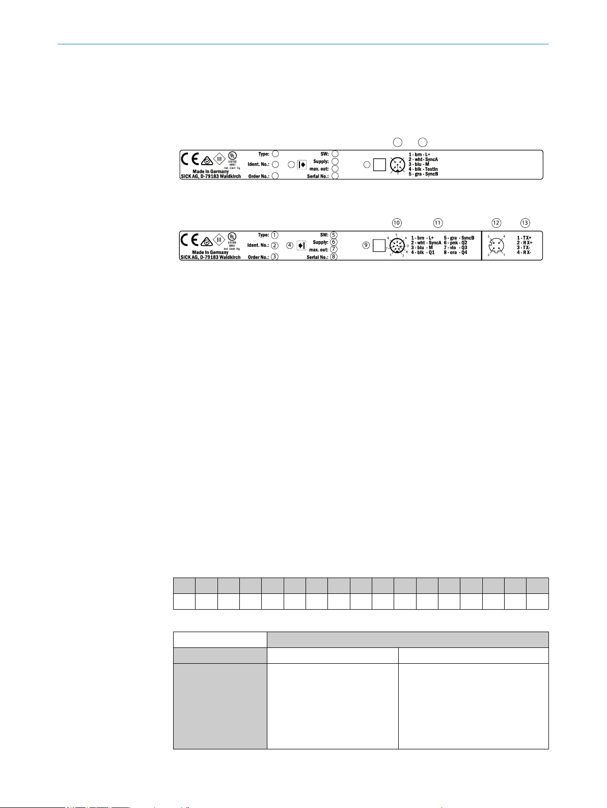
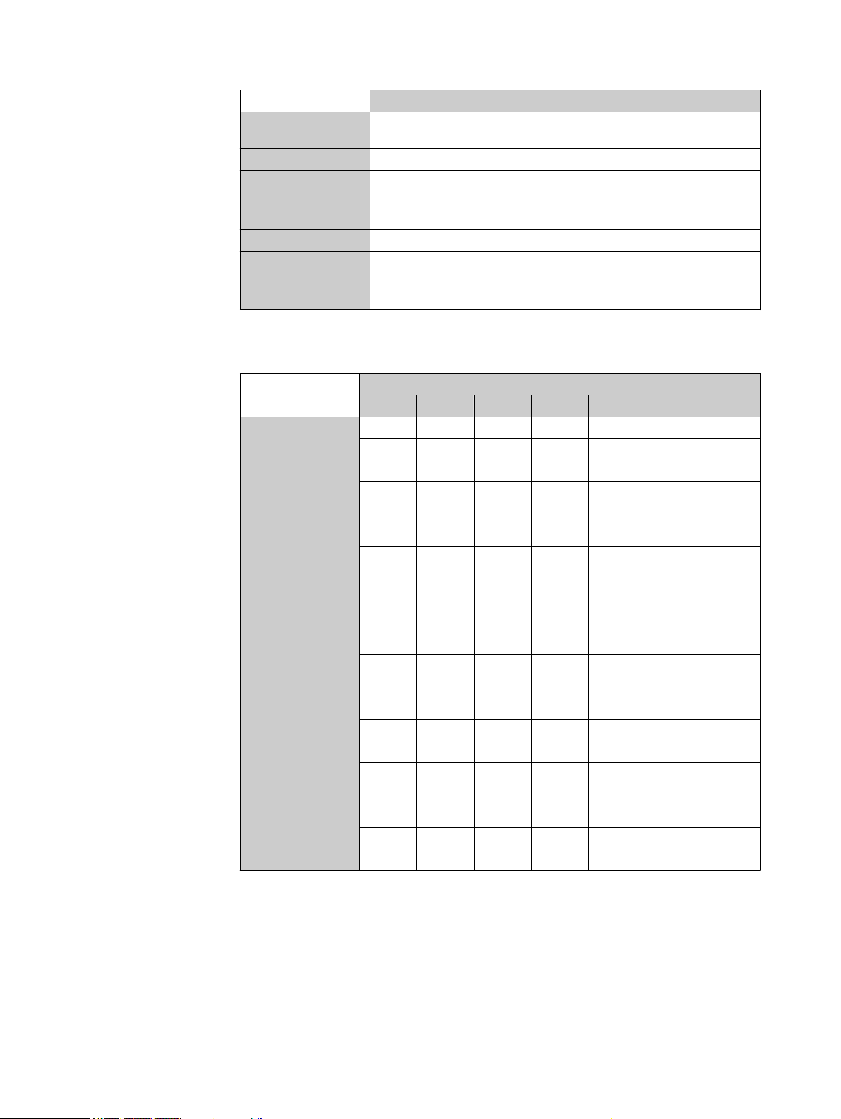
3.1 Type labels of the MLG-2 Pro
The MLG-2 Pro senders and receivers each have a type label.
Figure 1: Type label of sender
Figure 2: Type label of receiver
Type code
1
Part number for the individual sender or receiver
2
Part number of the entire MLG-2
3
Symbol for sender or receiver
4
Firmware version
5
Required power supply
6
Maximum output current
7
Serial number
8
2D matrix code, contains the order numbers of the sender/receiver, the order number of
9
the MLG-2, and the serial number
Diagram of the M12/5-pin or M12/8-pin male connector
ß
Pin assignment of the M12/5-pin or M12/8-pin male connector
à
Diagram of the M12/4-pin female connector
á
Pin assignment of the M12/4-pin female connector
â
PRODUCT DESCRIPTION 3
3.2 MLG-2 Pro type code
Example
MLG-2 with 5 mm beam separation, type Pro, detection height 145 mm, 1 input, 1
switching output and 2 analog outputs, no options, 5 m sensing range and pre-configu‐
ration for NBB,LBB,object detection and teach-in.
1 2 3 4 5 6 7 8 9 10 11 12 13 14 15 16 17
M L G 0 5 A - 0 1 4 5 B 1 0 5 0 1
Table 2: Example of an MLG-2 Pro type code
Position Meaning
1 … 3 Product family MLG
4 and 5 Beam separation 02 = 2.5 mm
05 = 5 mm
10 = 10 mm
20 = 20 mm
25 = 25 mm
30 = 30 mm
50 = 50 mm
Table 3: Meaning of the positions in the type code
8017460.ZIK1/2017-02-13 | SICK O P ER A TI N G I NS T RU C TI O NS | MLG-2 Pro
Subject to change without notice
11
Page 12
3 PRODUCT DESCRIPTION
Position Meaning
6 Type 0 = Special type
7 Hyphen –
8 … 11 Detection height 0000 = Special detection height
12 Interfaces, I/O see table 5, page 13
13 Options 1 = none
14 and 15 Optical properties see table 6, page 13
16 and 17 Preconfiguration of the I/O con‐
Table 3: Meaning of the positions in the type code
3.2.1 Monitoring height
Monitoring height
Table 4: Monitoring height [mm]
[mm]
A = Pro
see table 4, page 12
see "MLG-2 Pro preconfigurations",
nections and the software
page 13
Type
MLG02… MLG05… MLG10… MLG20... MLG25… MLG30... MLG50…
145 145 140 140 – – –
295 295 290 280 275 270 250
445 445 440 440 425 420 400
595 595 590 580 575 570 550
745 745 740 740 725 720 700
895 895 890 880 875 870 850
1045 1045 1040 1040 1025 1020 1000
1195 1195 1190 1180 1175 1170 1150
– 1345 1340 1340 1325 1320 1300
– 1495 1490 1480 1475 1470 1450
– 1645 1640 1640 1625 1620 1600
– 1795 1790 1780 1775 1770 1750
– 1945 1940 1940 1925 1920 1900
– 2095 2090 2080 2075 2070 2050
– 2245 2240 2240 2225 2220 2200
– 2395 2390 2380 2375 2370 2350
– 2545 2540 2540 2525 2520 2500
– – 2690 2680 2675 2670 2650
– – 2840 2840 2825 2820 2800
– – 2990 2980 2975 2970 2950
– – 3140 3140 3125 3120 3100
12
O PE R AT I NG IN S TR U CT I ON S | MLG-2 Pro 8017460.ZIK1/2017-02-13 | SICK
Subject to change without notice
Page 13
3.2.2 Combinations of MLG-2 Pro inputs and outputs
Position 12 Inputs and outputs, data interface Connection type
B 2 × switching output (Q) and
2 × analog output (QA)
or
1 × input (IN) and
1 × switching output (Q) and
2 × analog output (QA)
I 2 × switching output (Q) and
1 × RS-485 interface
or
1 × input (IN) and
1 × switching output (Q) and
1 × RS-485 interface
R 4 × switching output (Q)
or
2 × input (IN) and
2 × switching output (Q)
Table 5: Possible combinations of MLG-2 Pro inputs and outputs
PRODUCT DESCRIPTION 3
M12/8-pin, A-coded
M12/8-pin, A-coded
M12/8-pin, A-coded
3.2.3 Optical properties
Position
14 and 15
00 Special Special
32 2 m 2.5 mm
05 5 m 5 mm
08 8.5 m 5 mm
Table 6: Sensing range and minimum detectable object length
Sensing range Minimum detectable object length
3.2.4 MLG-2 Pro preconfigurations
Position
16, 17
01 NBB LBB Object detection Teach-in Standard operating
02 NBB LBB Object detection Object detection
03 NBB LBB Object detection Object detection
04 NBB FBB Object detection Teach-in Standard operating
05 NBB FBB Object detection Object detection
06 NBB FBB Object detection Object detection
Table 7: Preconfiguration of MLG-2 Pro with I/O combination B (see table 5, page 13)
QA1 QA2 Q1/C Q2/IN1 Teach-in
(inverted)
(inverted)
(inverted)
(inverted)
mode
Standard operating
mode
Standard & cross
beam operating
mode
mode
Standard operating
mode
Standard & cross
beam operating
mode
8017460.ZIK1/2017-02-13 | SICK O P ER A TI N G I NS T RU C TI O NS | MLG-2 Pro
Subject to change without notice
13
Page 14

3 PRODUCT DESCRIPTION
Position
16, 17
RS-485
Output
RS-485
Data transmis‐
Q1/C Q2/IN1 Teach-in
sion rate
01 System status
States of the
9600 baud Object detec‐
tion
Teach-in Standard
switching outputs
NBB
LBB
FBB
ODI
IDI
02 System status
States of the
9600 baud Object detec‐
tion
Teach-in Standard
switching outputs
Beam status
03 System status
States of the
9600 baud Object detec‐
tion
Object detec‐
tion (inverted)
switching outputs
Beam status
04 System status
States of the
9600 baud Object detec‐
tion
Teach-in Standard
switching outputs
RLC
05 System status
States of the
9600 baud Object detec‐
tion
Object detec‐
tion (inverted)
switching outputs
RLC
Table 8: Preconfiguration of MLG-2 Pro with I/O combination I (see table 5, page 13)
operating
mode
operating
mode
Standard
operating
mode
operating
mode
Standard
operating
mode
Position
Q1/C Q2/IN1 Q3 Q4/IN2 Teach-in
16, 17
01 Object detection Teach-in Object detec‐
tion
Object detec‐
tion
Standard
operating
mode
02 Object detection Teach-in Object detec‐
tion (inverted)
Object detec‐
tion
Standard
operating
mode
03 Object detection Teach-in Object detec‐
tion
Object detec‐
tion
Standard &
cross beam
operating
mode
04 Object detection Object detection Object detec‐
tion
Object detec‐
tion
Standard
operating
mode
05 Object detection Object detection
(inverted)
Object detec‐
tion (inverted)
Object detec‐
tion (inverted)
Standard
operating
mode
06 Object detection Object detection Object detec‐
tion
Object detec‐
tion (inverted)
Standard &
cross beam
operating
mode
Table 9: Preconfiguration of MLG-2 Pro with I/O combination R (see table 5, page 13)
14
O PE R AT I NG IN S TR U CT I ON S | MLG-2 Pro 8017460.ZIK1/2017-02-13 | SICK
Subject to change without notice
Page 15
3.3 MLG-2 product properties
Different beam separations from 2.5 mm to 50 mm
•
Monitoring heights from 130 to 3,140 mm
•
Operating range up to 2 m, 5 m or 8.5 m
•
Quick response time
•
Convenient configuration using the SOPAS ET software interface
•
Detection of transparent objects
•
Dust- and sunlight-resistant
•
Integrated applications including object detection, height classification, etc.
•
3.4 Setup and function
The MLG-2 is an optical light grid. It comprises a sender and a receiver.
The sender consists of sender optics, several sender elements (LEDs), and actuation
electronics. The receiver consists of receiver optics, several receiver elements (photodi‐
odes) and evaluation electronics.
3.4.1 MLG-2 Pro device components
PRODUCT DESCRIPTION
3
Figure 3: MLG-2 Pro
Receiver
r
Sender
s
Receiver connection
1
Ethernet configuration interface on the receiver
2
Sender connection
3
The receiver has a connection for the power supply, for inputs and outputs, and for syn‐
chronization. It also has an Ethernet connection for configuration via TCP/IP.
The sender has a connection for the power supply, for synchronization, and for a test
input.
8017460.ZIK1/2017-02-13 | SICK O P ER A TI N G I NS T RU C TI O NS | MLG-2 Pro
Subject to change without notice
15
Page 16

3 PRODUCT DESCRIPTION
3.4.2 Measurement principle
Provided no object is located between the sender and receiver elements, the light
beams from the sender elements will hit the receiver elements.
If an object is located between the sender and receiver elements, the light beams will
be blocked, depending on the size of the object.
Detection area
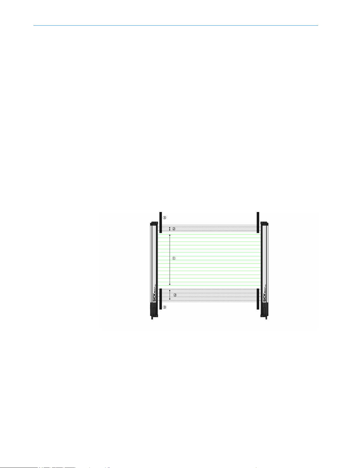
Figure 4: Detection area of the MLG-2
Monitoring height
1
Beam separation
2
Sensing range
3
The detection area is determined by the monitoring height and the sensing range of the
light grid. The monitoring height is determined by the beam separation and the number
of beams. The sensing range of the light grid is the distance between sender and
receiver.
3.4.3 Synchronizing the MLG-2
The sender and receiver synchronize with each other electronically, thus one electrical
connection between the sender and receiver is necessary.
3.4.4 Beam separations and monitoring height
Beam separations
In order to achieve different levels of measurement accuracy, the MLG-2 is available
with different beam separations.
16
O PE R AT I NG IN S TR U CT I ON S | MLG-2 Pro 8017460.ZIK1/2017-02-13 | SICK
Subject to change without notice
Page 17
PRODUCT DESCRIPTION 3
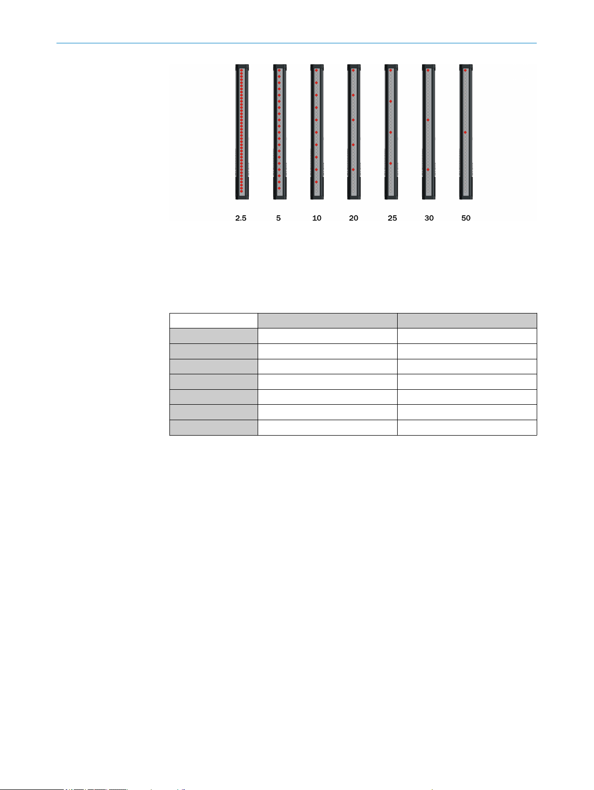
Figure 5: Schematic depiction of available beam separations (mm)
Maximum and minimum monitoring height
The number of LEDs is limited to 510. This results in different maximum monitoring
heights depending on the beam separation. The minimum monitoring height is deter‐
mined by the beam separation and the smallest module size for this beam separation.
3.4.5 Teach-in
Beam separation Maximum monitoring height Minimum monitoring height
2.5 mm 1195 mm 145 mm
5 mm 2,545 mm 145 mm
10 mm 3,140 mm 140 mm
20 mm 3,130 mm 130 mm
25 mm 3,125 mm 275 mm
30 mm 3,1320 mm 270 mm
50 mm 3,100 mm 250 mm
Table 10: Maximum monitoring heights
During the teach-in process, the switching thresholds for all beams are individually
adjusted for the sensing range and the ambient conditions.
After teach-in has been completed, it must be ensured that the setup is no longer
changed otherwise another teach-in will have to be carried out.
The MLG-2 Pro provides the following options for carrying out a teach-in:
Pressing the teach-in button
•
Automatic teach-in (when switching on)
•
Signal at a switching input
•
SOPAS ET
•
IO-Link
•
Webserver
•
Teach-in quality
The teach-in quality indicates the quality after the teach-in process. The MLG-2 calcu‐
lates this value based on the quality of the light level received. The teach-in quality
depends on the alignment of the MLG-2 and the cleanliness of the front screens.
The value remains constant until another teach-in process is carried out.
8017460.ZIK1/2017-02-13 | SICK O P ER A TI N G I NS T RU C TI O NS | MLG-2 Pro
Subject to change without notice
17
Page 18
3 PRODUCT DESCRIPTION
Process quality
The process quality indicates the quality of the light level currently being received. The
MLG-2 analyzes the light level received when the light path is unblocked and compares
this to the values after the last teach-in process.
If the received values are getting worse, the process quality drops.
Possible causes of a drop in process quality include:
•
•
•
Retrieving teach-in quality and process quality data
The quality performance indicators can be retrieved in various ways:
•
•
•
•
•
•
Contamination or fogging of the front screen of the sender and/or receiver
Misalignment
Continuous partial blocking of a light beam or several light beams
SOPAS ET
RS485
IO-Link
Integrated web server
switching outputs
Analog outputs
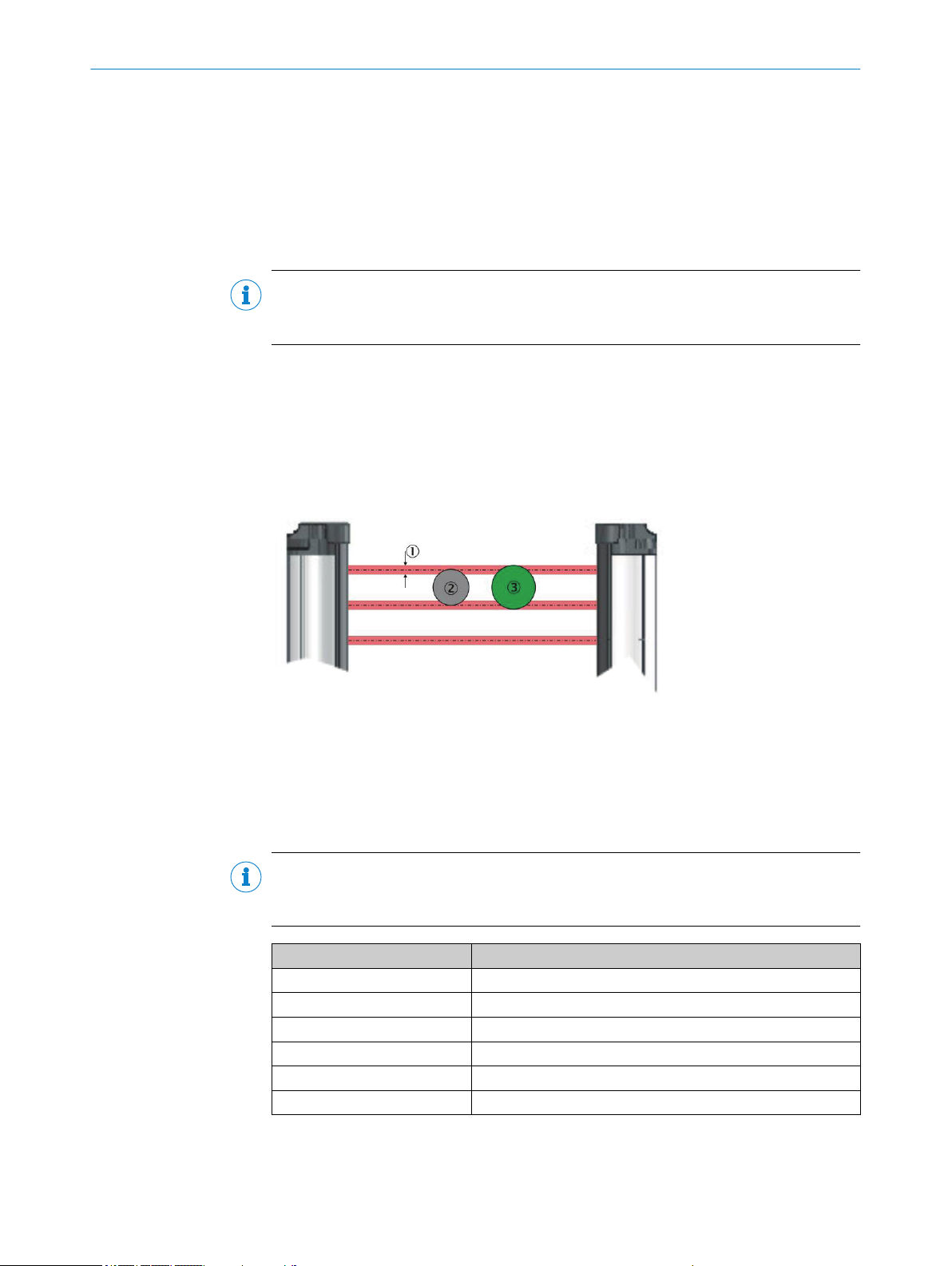
3.4.6 Beam blanking
Individual beams can be blanked.
Figure 6: Detection area with beams blanked
1
2
3
Included beams
Blanked beams
Structural restrictions on the detection area
18
The MLG-2 Pro offers various options for blanking light beams (see "Teach-in",
page 90).
One-off blanking
•
The blocked beams are blanked.
Beam blanking for each teach-in
•
The blocked beams are blanked in every teach-in process.
O PE R AT I NG IN S TR U CT I ON S | MLG-2 Pro 8017460.ZIK1/2017-02-13 | SICK
Subject to change without notice
Page 19

NOTE
If this option is selected and an object is located in the detection area during the teachin process, this will not be identified as an error.
3.4.7 Sensing ranges
Operating range
Light grids are generally available with a 2 m range, 5 m range or 8.5 m sensing range.
This is referred to as the operating range, which includes an operating reserve.
Limiting range
It is also possible to operate the MLG-2 up to its limiting range, which goes beyond the
operating range.
Table 11: Limiting range
PRODUCT DESCRIPTION 3
Manual blanking
•
Light beams can be individually selected and blanked using the interface in
SOPAS ET and via IO-Link (see "Representation of the detection area", page 59).
The beams are not taken into account in the measurement, even if they are made
at the time of the teach-in process.
Operating range Limiting range
2 m 2.8 m
5 m 7 m
8.5 m 12 m
3.5 Scan time
Operation within the limiting range requires the following conditions:
Clean ambient conditions
•
Front screens are cleaned regularly
•
Regular teach-in
•
The following functions cannot be provided when operating within the limiting range:
High level of operating reserves
•
High measurement accuracy
•
Transparent operating mode
•
Dust- and sunlight-resistant operating mode
•
NOTE
The sensing range of the MLG-2 Pro is reduced in certain operating modes (see "MLG-2
operating modes", page 26).
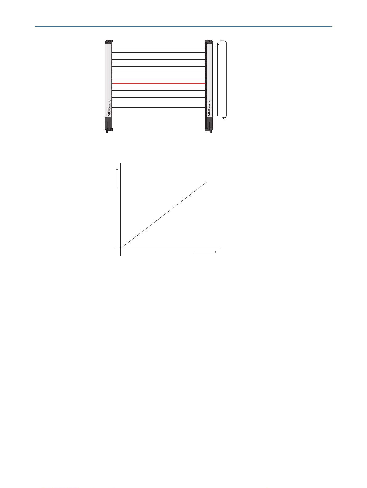
In the MLG-2, not all light beams are active at the same time, instead one light beam is
activated after the other starting from the bottom.
8017460.ZIK1/2017-02-13 | SICK O P ER A TI N G I NS T RU C TI O NS | MLG-2 Pro
Subject to change without notice
19
Page 20
Number of beams
Scan time
3 PRODUCT DESCRIPTION
Figure 7: Standard scan method
The scan time increases according to the number of beams of an MLG-2.
Figure 8: Scan time in relation to the number of beams
The scan time is used to determine the response times of the outputs, the minimum
presence time of an object and the repeat accuracy of a measurement result (reprodu‐
cibility).
The response time is the time it takes for an output to react following the detec‐
•
tion of an object/gap. The maximum response time is 3 × the scan time plus the
transmission time to the outputs.
The minimum presence time is the time an object or a gap has to be in the detec‐
•
tion area for it to be detected. The minimum presence time is max. 2 × the scan
time.
The repeat accuracy of a measurement result (reproducibility) is the amount of
•
time by which an object detection can differ from a previous or subsequent detec‐
tion. The reproducibility time is 1 × the scan time.
3.5.1 Response time, minimum presence time and reproducibility of the MLG-2
On the MLG-2, the response time, minimum presence time, and reproducibility are dis‐
played via SOPAS ET. Response time and minimum dwell time can be read off in the
diagramsee figure 129, page 122.
3.5.2 Scan time with cross-beam function
When the cross-beam function is enabled, the light beam from a sender LED is
received by three receiver diodes in two scans. This doubles the scan time.
20
O PE R AT I NG IN S TR U CT I ON S | MLG-2 Pro 8017460.ZIK1/2017-02-13 | SICK
Subject to change without notice
Page 21
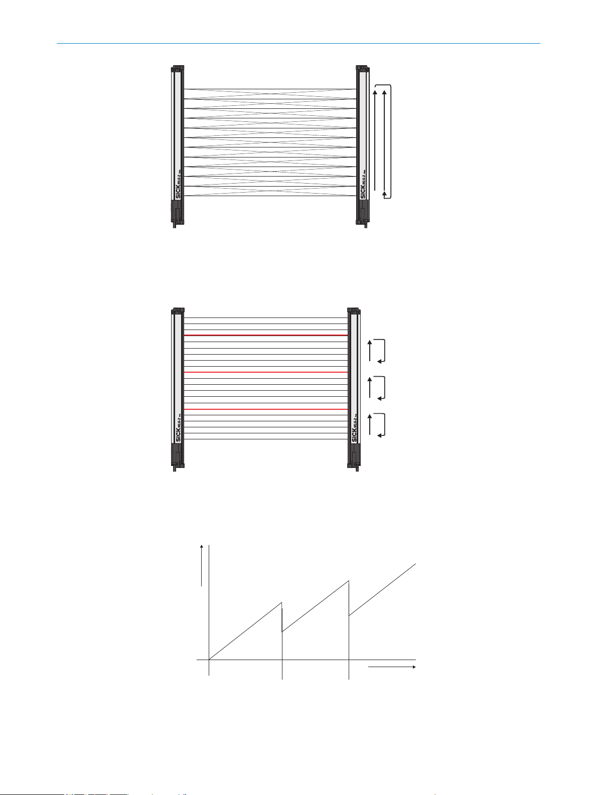
Figure 9: Cross-beam function
Number of beams
Scan time
1 2
3.5.3 Scan time with high-speed scan on the MLG-2
With high-speed scan, several beams are active in each cycle. This reduces the scan
time by a variable factor.
PRODUCT DESCRIPTION 3
Figure 10: High-speed scan
The scan time is also dependent on the number of beams. Beyond a certain number of
beams, the scan time is reduced because it is possible to use the high-speed scan.
Figure 11: Scan time in relation to the number of beams when using the high-speed scan
High-speed scan with 2 beams active simultaneously
1
8017460.ZIK1/2017-02-13 | SICK O P ER A TI N G I NS T RU C TI O NS | MLG-2 Pro
Subject to change without notice
21
Page 22
3 PRODUCT DESCRIPTION
High-speed scan with 3 beams active simultaneously
2
The number of beams that can be activated at the same time depends on the size of
the detection area (sensing range, beam separation, and number of beams). On the
MLG-2, the response time, minimum presence time, and reproducibility are displayed
via SOPAS ET. You can also find the response time and minimum presence time when
using the high-speed scan in the diagrams in these operating instructions (see "Dia‐
grams", page 122).
NOTE
With a beam separation of 2.5 mm, the high-speed scan can only be adjusted in combi‐
nation with the high measurement accuracy function.
3.6 Beam separation and minimum detectable object
The measurement accuracy achieved by the MLG-2 depends on the beam separation.
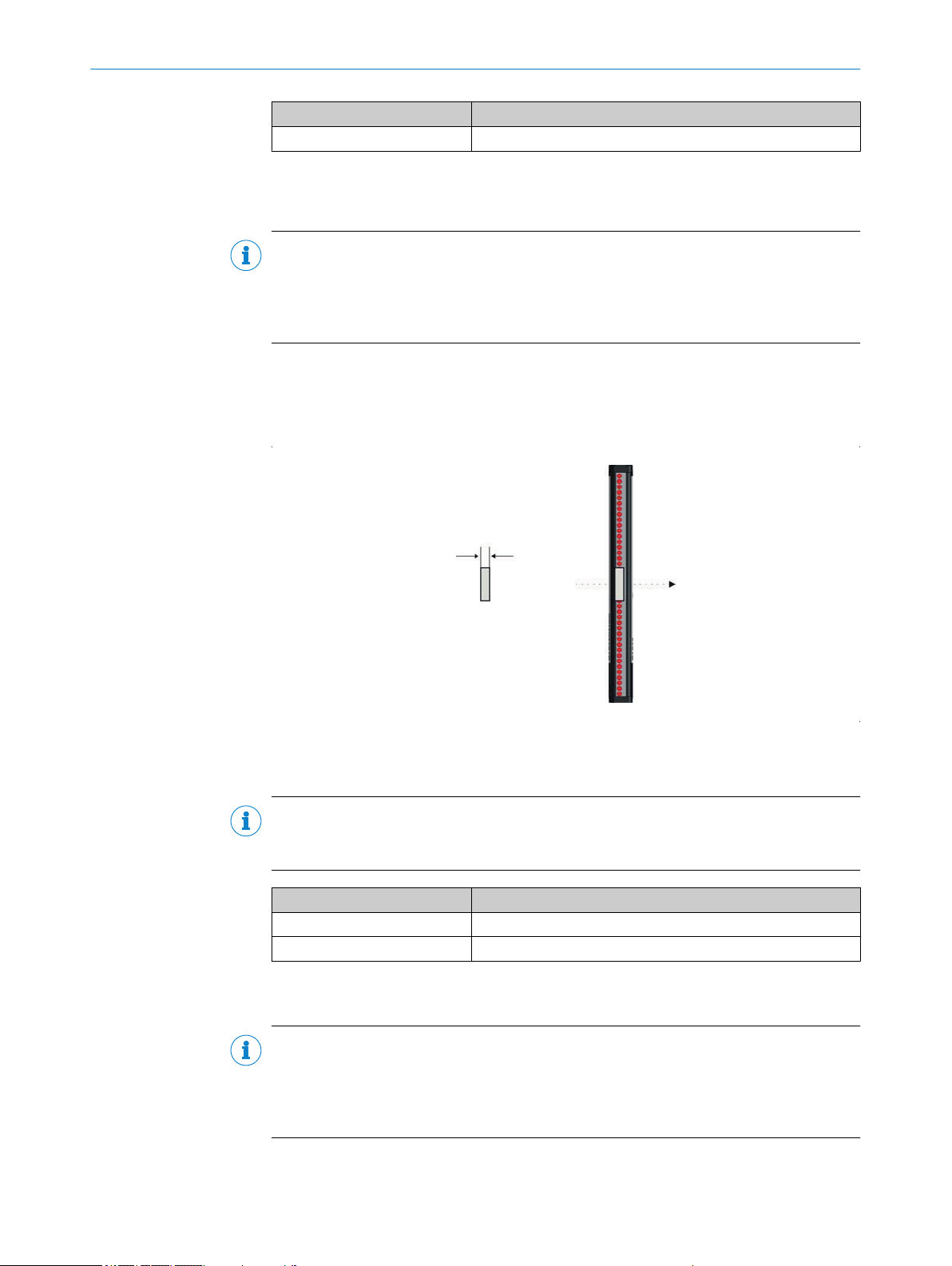
3.6.1 Minimum detectable object with parallel-beam function
In order for an object to be detected continuously, it must completely cover at least one
beam. This is referred to as the minimum detectable object, or MDO.
Figure 12: Minimum detectable object
Beam diameter
1
Object is not completely reliably detected
2
Object is reliably detected (meets requirements of minimum detectable object size)
3
NOTE
For moving objects, the minimum detectable object depends on the speed of the
object.
Beam separation Minimum detectable object (stationary object)
2.5 mm 3.5 mm
5 mm 9 mm
10 mm 14 mm
20 mm 24 mm
25 mm 29 mm
30 mm 34 mm
Table 12: Minimum detectable object in relation to the beam separation of the MLG-2
12
22
O PE R AT I NG IN S TR U CT I ON S | MLG-2 Pro 8017460.ZIK1/2017-02-13 | SICK
Subject to change without notice
Page 23
1
PRODUCT DESCRIPTION 3
Beam separation Minimum detectable object (stationary object)
50 mm 54 mm
Table 12: Minimum detectable object in relation to the beam separation of the MLG-2
1
Only if the object also meets the minimum detectable object length requirements.
2
All the values are typical values and can be found in the respective setting modes.
NOTE
The minimum detectable object size is also dependent on the other performance
options, such as the configured response time and operating reserve. The precise mini‐
mum detectable object size is displayed in SOPAS ET on the MLG-2 (see "SOPAS ET
interface", page 54).
3.6.2 Minimum detectable object length
When an object moves through the detection area, it must have a certain length.
12
Figure 13: Minimum detectable object length
Minimum detectable object
1
NOTE
For moving objects, the minimum detectable object length also depends on the speed
of the object.
Beam separation Minimum detectable object length (stationary object)
2.5 mm 2.5 mm
5 … 50 mm 5 mm
Table 13: Minimum detectable object length with the MLG-2
1
Only if the object also meets the minimum detectable object requirements.
1
NOTE
The minimum detectable object length is also dependent on the other performance
options, such as the configured response time and operating reserve. The precise mini‐
mum detectable object length is displayed in SOPAS ET on the MLG-2 (see "SOPAS ET
interface", page 54).
8017460.ZIK1/2017-02-13 | SICK O P ER A TI N G I NS T RU C TI O NS | MLG-2 Pro
Subject to change without notice
23
Page 24
3 PRODUCT DESCRIPTION
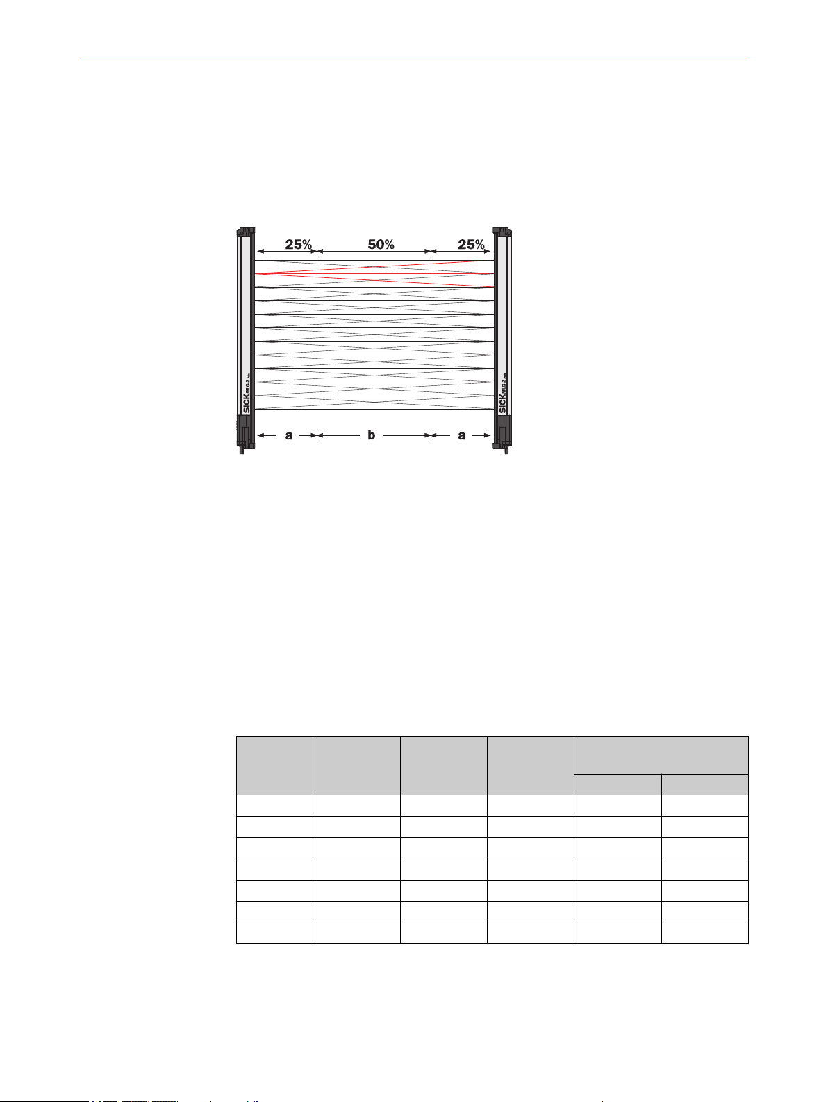
3.6.3 Minimum detectable object with cross-beam function
The parallel-beam function is used for measuring by default. With the parallel-beam
function, each light beam is received only by the receiver element situated directly
opposite.
With the cross-beam function, a sender LED projects beams to several receiver diodes.
The cross-beam function increases the measurement accuracy and enables the detec‐
tion of smaller objects.
Figure 14: Cross-beam function
A minimum distance between the sender and the receiver is required for the crossbeam function. The minimum detectable object size depends on the position of the
object within the detection area. Detection of the smaller minimum detectable object
size is therefore only possible in the central area (b) of the detection area.
The cross-beam function is only useful for object detection (NBB ≤ 1). For other
•
applications (height classification, object recognition, etc.), the results of the paral‐
lel-beam function are used.
Use of the cross-beam function increases the response time.
•
With the cross-beam function, a minimum distance needs to be maintained
•
between sender and receiver. The minimum distance depends on the aperture
angle of the light grid.
For moving objects for the cross-beam function, the minimum detectable object
•
depends on the speed of the object.
Beam sepa‐
ration
2.5 mm 200 mm – – 2.5 mm 4 mm
5 mm – 110 mm 120 mm 6.5 mm 9 mm
10 mm – 220 mm 240 mm 9 mm 14 mm
20 mm – 440 mm 480 mm 14 mm 24 mm
25 mm – 550 mm 600 mm 16.5 mm 29 mm
30 mm – 660 mm 720 mm 19 mm 34 mm
50 mm – 1110 mm 1200 mm 29 mm 54 mm
Table 14: Minimum detectable object with cross-beam function on the MLG-2
Minimum dis‐
tance
2 m variant
Minimum dis‐
tance
5 m variant
Minimum dis‐
tance
8.5 m variant
Minimum detectable object
(stationary object)
In area B In area A
24
O PE R AT I NG IN S TR U CT I ON S | MLG-2 Pro 8017460.ZIK1/2017-02-13 | SICK
Subject to change without notice
Page 25
PRODUCT DESCRIPTION 3
High-speed scan is not possible.
•
The minimum detectable object size with cross-beam function is also dependent
•
on the other performance options, such as the configured response time and
operating reserve. The precise minimum detectable object size is displayed in
SOPAS ET on the MLG-2 (see "SOPAS ET interface", page 54).
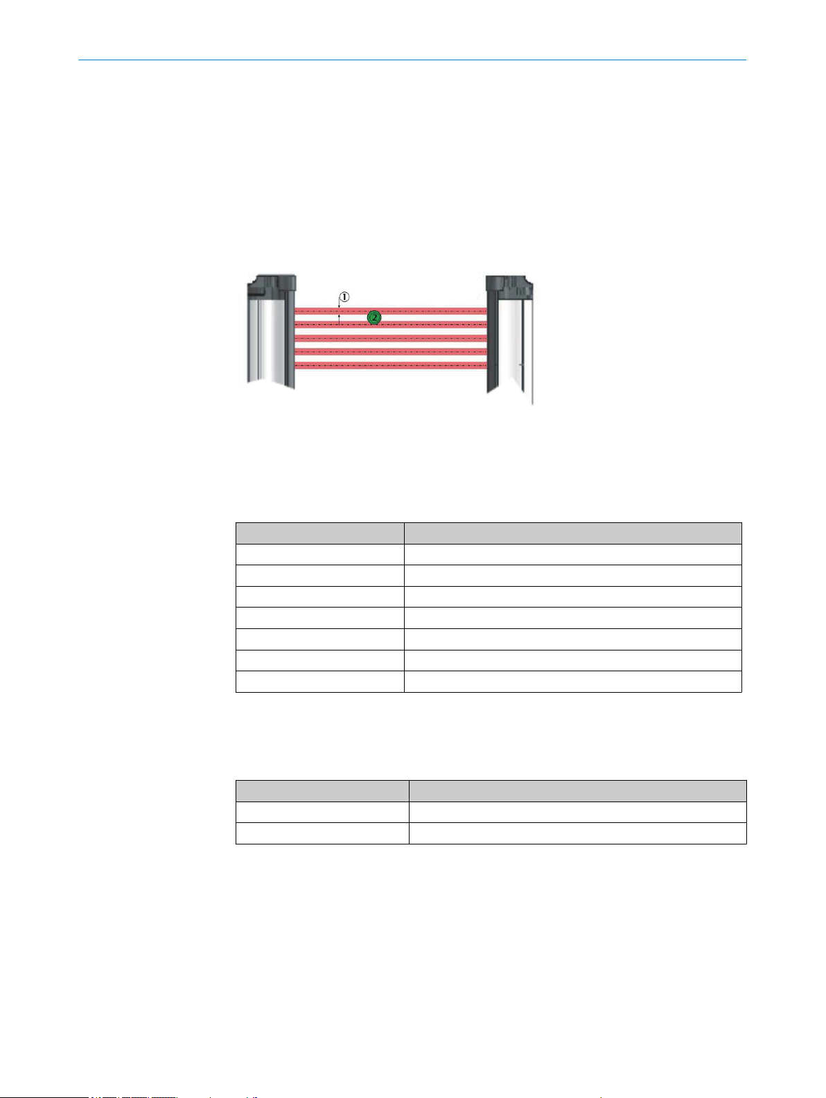
3.6.4 Minimum detectable object with high measurement accuracy from the MLG-2
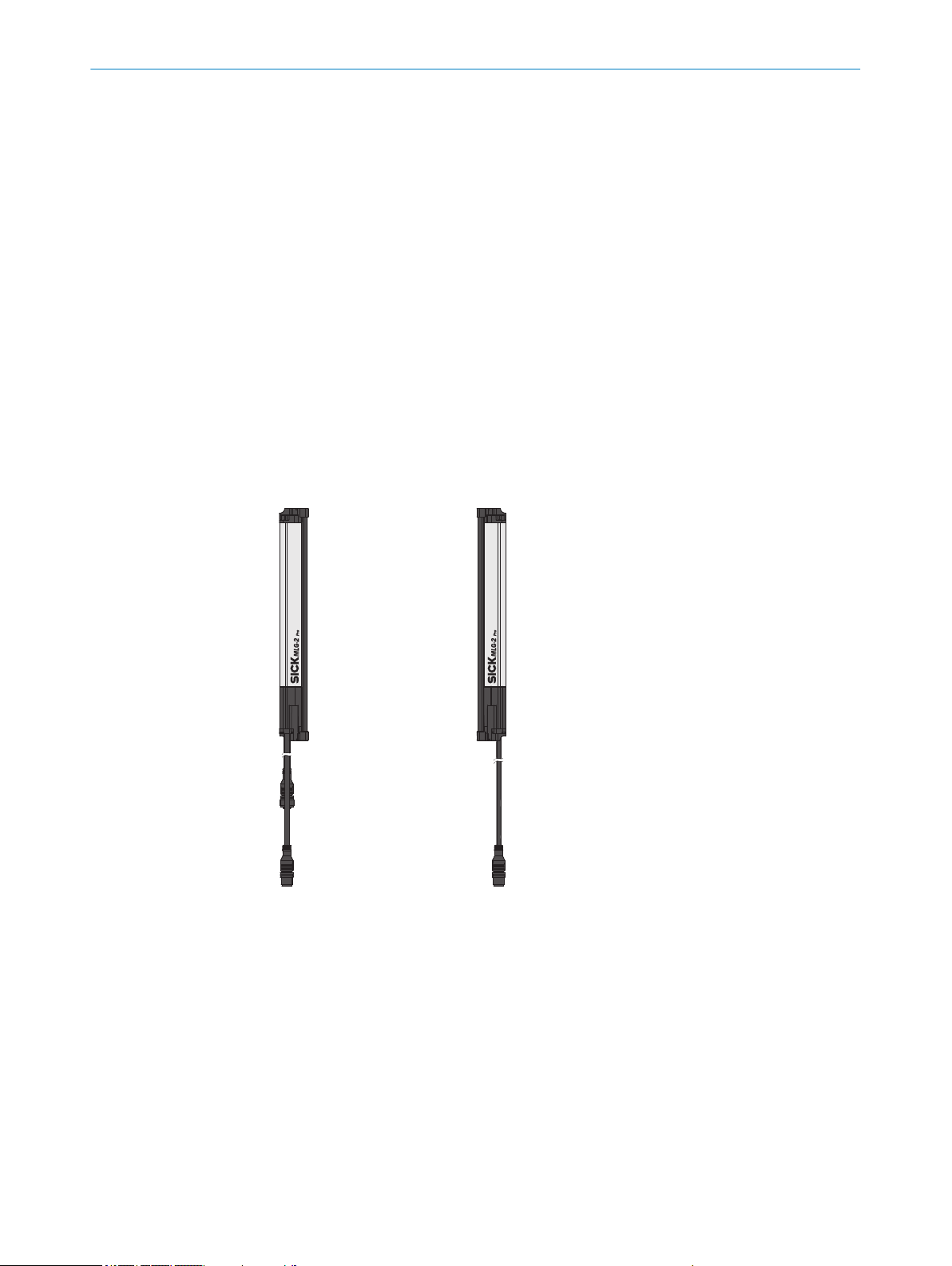
On the MLG-2, the measurement accuracy can be increased in SOPAS ET (see "Per‐
formance options", page 93). This means that an object can be detected even if it
only covers half of a beam.
Figure 15: Minimum detectable object size with high measurement accuracy
Beam diameter
1
Object is reliably detected (meets requirements of minimum detectable object size)
2
Beam separation Minimum detectable object (stationary object)
1
2.5 mm 2.5 mm
5 mm 5 mm
10 mm 10 mm
20 mm 20 mm
25 mm 25 mm
30 mm 30 mm
50 mm 50 mm
Table 15: Minimum detectable object size with high measurement accuracy
1
Only if the object also meets the minimum detectable length requirements see table 13, page 23).
Minimum detectable object length
Beam separation Minimum detectable object length (stationary object)
2.5 mm 1 mm
5 … 50 mm 2 mm
Table 16: Minimum detectable object length with high measurement accuracy
1
Only if the object also meets the minimum detectable length requirements (see table 12, page 22).
1
8017460.ZIK1/2017-02-13 | SICK O P ER A TI N G I NS T RU C TI O NS | MLG-2 Pro
Subject to change without notice
25
Page 26

3 PRODUCT DESCRIPTION
When using high measurement accuracy to detect moving objects, the minimum
•
detectable object length also depends on the speed of the object and the other
performance options, such as the configured response time and operating
reserve. The precise minimum detectable object length is displayed in SOPAS ET
on the MLG-2 (see "SOPAS ET interface", page 54).
Sensing ranges larger than the operating range are not possible when using high
•
measurement accuracy.
High measurement accuracy can cause the operating reserve to decrease in the
•
event of large sensing ranges and imperfect alignment.
3.7 Operating reserve
The operating reserve defines the operational safety before contamination, vibrations,
misalignment, temperature fluctuations, etc. cause the MLG-2 to produce incorrect
measurements.
The MLG-2 is subject to a certain level of contamination depending on its environment
and application. In principle, the MLG-2 must be cleaned regularly and a teach-in
should be carried out after cleaning.
3.7.1 Operating reserves on the MLG-2
On the MLG-2, the operating reserve can be adjusted according to the operating mode.
Standard operating reserve
The standard setting for the operating reserve is the best setting for most applications.
High level of operating reserves
Setting the operating reserve high makes the MLG-2 very resistant to contamination.
However, it is not possible to activate high measurement accuracy in this case.
NOTE
In order to achieve a high operating reserve, the input sensitivity must be increased.
This increases the risk of reflection. If there are reflective surfaces near the detection
area, the light beams from the LEDs may reflect off these surfaces and reach the
receiver, even though there is an object in the detection area.
The high input sensitivity means that only opaque objects can be detected. Transparent
or semi-transparent objects are not detected.
Low operating reserve
Setting the measurement accuracy high reduces the operating reserve. When the oper‐
ating reserve is low, the MLG-2 must be cleaned more frequently and a teach-in proc‐
ess must be carried out.
3.8 MLG-2 operating modes
The MLG-2 has the operating modes Standard, Transparent and Dust and SunlightResistant.
Within the operating modes, the performance options can be used to modify the
response time, minimum detectable object size, minimum detectable absorption (in
Transparent operating mode), and operating reserve.
The configurable performance options depend on the operating mode selected.
•
When the operating mode is changed, a new teach-in process must be performed.
•
26
O PE R AT I NG IN S TR U CT I ON S | MLG-2 Pro 8017460.ZIK1/2017-02-13 | SICK
Subject to change without notice
Page 27

3.8.1 Standard operating mode
Standard operating mode is the mode in which most measuring applications can be
carried out.
Only opaque objects can be detected.
•
There must not be a high level of constant light irradiation.
•
3.8.2 Transparent operating mode
Transparent operating mode enables the detection of transparent objects, such as
those made of glass, PET, etc.
Transparent objects do not completely cover the light beam. In order to detect these
objects, they must have what is known as a minimum detectable absorption (MDA).
NOTE
It is not possible to use the cross-beam function, high operating reserve or high-speed
scan in the Transparent operating mode.
Minimum detectable absorption
In order to detect a transparent object, it must absorb a certain percentage of the
energy from the light beam. Depending on the objects being measured, an object can
be detected with 30% absorption, 15% absorption, or 10% absorption.
PRODUCT DESCRIPTION 3
NOTE
The minimum detectable absorption that an object needs in order to be detected
increases with the sensing range (see "Minimum detectable absorption", page 124).
Examples of the signal attenuation of transparent objects1):
Approx. 10% signal attenuation:
•
Clean PET bottles, clear glass, thin and clear films (e.g., cellophane), household
plastic film, plastic wrapping
Approx. 15% signal attenuation:
•
Clean clear glass bottles, thick films, film and wrapping folded multiple times
Approx. 30% signal attenuation:
•
Green and brown glass, colored glass bottles
The following prerequisites must be met:
The sender and receiver must be aligned precisely with one another.
•
The sender and receiver elements must be kept clean at all times.
•
AutoAdapt
The AutoAdapt function is active in the Transparent operating mode. AutoAdapt adjusts
the switching threshold at which objects are detected in accordance with the level of
contamination on the MLG-2. As a result, the MLG-2 thus becomes less sensitive as the
level of contamination increases.
3.8.3 Dust- and sunlight-resistant operating mode
Dust and sunlight-resistant operating mode is intended for applications when there is a
large amount of dust in the environment or a high level of solar radiation.
Dust and sunlight-resistant operating mode reduces the maximum sensing range
•
1)
Examples are for illustrative purposes only. The signal attenuation and the minimum detectable absorption to be configured must be
determined for each individual application.
8017460.ZIK1/2017-02-13 | SICK O P ER A TI N G I NS T RU C TI O NS | MLG-2 Pro
Subject to change without notice
27
Page 28
3 PRODUCT DESCRIPTION
•
3.9 Interfaces
The MLG-2 can be used to evaluate the measurements in different ways. The MLG-2
provides various interfaces for data output.
•
•
•
•
The MLG-2 can output the raw data via the interfaces in the form of the beam status or
run-length code, so the user can evaluate the data him/herself.
The MLG-2 can also preprocess the raw data (beam function, e.g., NBB – number of
beams blocked) and output the data via bus or analog interfaces.
The preprocessed data can be assigned directly to the switching outputs via a program‐
mable function logic or via predefined applications.
– To 1.2 m for devices with a 2 m operating range
– To 3 m for devices with a 5 m operating range
– To 5 m for devices with an 8.5 m operating range
This operating mode can only be configured on an MLG-2 with fewer than
240 beams.
Switching outputs (Push-Pull)
Analog outputs
RS-485 interface
IO-Link interface
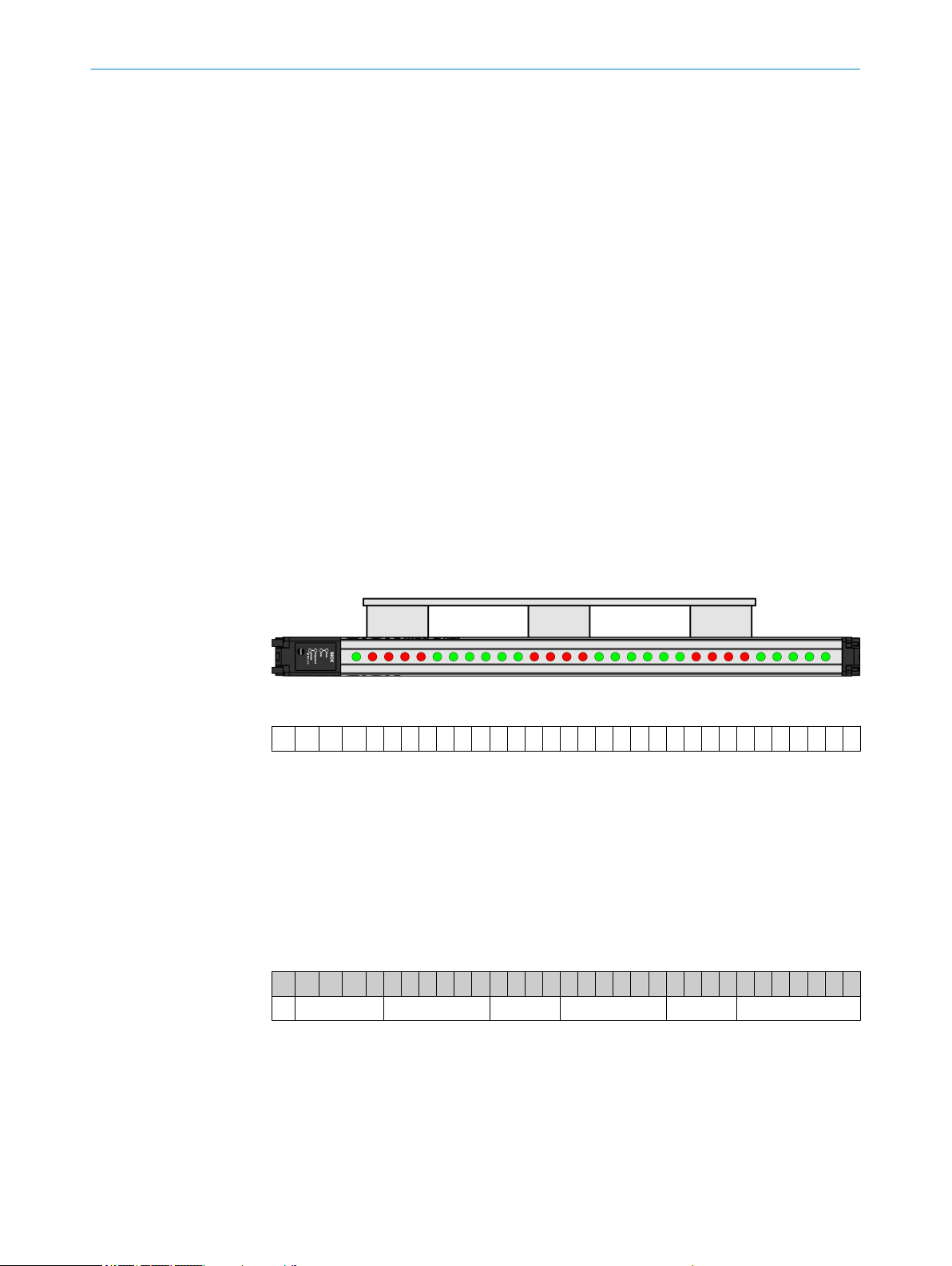
3.9.1 Output of measurement data (raw data)
The MLG-2 provides the status of all beams at its data interface using a data message.
Figure 16: Status of the beams
0 1 1 1 1 0 0 0 0 0 0 1 1 1 1 0 0 0 0 0 0 1 1 1 1 0 0 0 0 0 0 0
Table 17: Example status for an MLG-2 with 32 beams
0
Beam clear
1
Beam blocked
The data message can be output continuously or in response to particular events.
Run-length code
In order to reduce the volume of data, the run-length code can be output instead of the
complete status of all beams. This code only contains the status change of the beams.
The run-length code indicates how many beams currently have the same status.
0 1 1 1 1 0 0 0 0 0 0 1 1 1 1 0 0 0 0 0 0 1 1 1 1 0 0 0 0 0 0 0
1 4 6 4 6 4 7
Table 18: Example status for the run-length code of an MLG-2 with 32 beams
28
RLC = 1464645
The example shows: 1 beam made, 4 beams blocked, 6 beams made, 4 beams
blocked, 6 beams made, 4 beams blocked, 5 beams made.
The first value always indicates the number of unblocked beams. If the first beam is
blocked, the first value will therefore be zero. The second value indicates how many
beams are blocked; in the example in table 19, this value = 1.
O PE R AT I NG IN S TR U CT I ON S | MLG-2 Pro 8017460.ZIK1/2017-02-13 | SICK
Subject to change without notice
Page 29

1 0 0 1 1 1 1 0 0 0 0 1 1 0 0 0 0 0
0 1 2 4 4 2 5
Table 19: Example run-length code with the first beam blocked
NOTE
The run-length code can contain a maximum of 16 values; i.e., 15 status changes. It is
therefore only useful for measuring objects with a small number of parts, e.g., a pallet.
Objects such as pallet cages are not suitable as they involve too many status changes.
3.9.2 Preliminary evaluation
Beam functions for preliminary evaluation
The MLG-2 creates a preliminary evaluation on the basis of the beam status, e.g.:
NBB – Number of Beams Blocked
•
NBM – Number of Beams Made
•
LBB – Last Beam Blocked
•
FBB – First Beam Blocked
•
see table 33, page 107: Table shows all available functions.
The results of the preliminary evaluation can be output via the data interfaces and
processed further externally. Alternatively, they can first be processed in a function pro‐
gramming option in the MLG-2.
PRODUCT DESCRIPTION 3
Function programming for the MLG-2 Pro
Function programming can be used to carry out complex applications with variables,
operands, and functions in SOPAS ET.
1st option:
The beam functions are directly linked with the outputs.
Example:
Q1 = Total number of beams made (NBM) ≥ 30
The output Q1 switches when the total number of beams made is greater than or
equal to 30.
2nd option:
The MLG-2's beam functions are used to define beam function variables first.
Example:
BFVar 1: Total number of beams made (NBM) ≥ 30
BFVar 2: Number of consecutive beams blocked (NCBB) = 5
These can be linked to logical variables.
Example:
LogVar1 = BFVar 1 OR BFVar 2
The logical variables can be linked in turn to the outputs (Q).
Example:
Q1 = LogVar1 = true
The output Q1 switches when the total number of beams made is greater than or
equal to 30 or when the number of consecutive beams blocked equals 5.
3.9.3 Configurable applications of the MLG-2 Pro
The MLG-2 provides predefined applications which are assigned to the outputs. The fol‐
lowing options are available for configuring the applications:
8017460.ZIK1/2017-02-13 | SICK O P ER A TI N G I NS T RU C TI O NS | MLG-2 Pro
Subject to change without notice
29
Page 30

3 PRODUCT DESCRIPTION
– Via SOPAS ET (see "Configuration with SOPAS ET", page 53)
– Using the integrated web server (see "MLG-2 configuration with the internal web
– Using IO-Link (see "IO-Link", page 110)
Application MLG-2 Pro
Height classification
Object detection/object width
Contamination warning
Object recognition
Hole detection/hole size
Outer/inner dimension
Classification of the object position
Classification of the hole position
Zones
Diagnostics
Table 20: Configurable applications for switching outputs
Application MLG-2 Pro
NBB Object detection
NBM Hole detection
LBB Object height measurement (last beam
FBB Object height measurement (first beam
ODI Measurement of the outer dimension
IDI Measurement of the inner dimension
CBB Measurement of the object position
CBM Measurement of the hole position
– Diagnostics
NBB Zone X
(X = 1, 2, 3
or 4)
NCBB Zone
X (X = 1, 2,
3 or 4)
FBB Zone X
(X = 1, 2, 3
or 4)
LBB Zone X
(X = 1, 2, 3
or 4)
CBB Zone X
(X = 1, 2, 3
or 4)
Table 21: Configurable applications for analog outputs
server", page 108)
blocked)
blocked)
Object detection system within a zone
Object width within a zone
Object height measurement (first beam
blocked) within a zone
Object height measurement (last beam
blocked) within a zone
Object position within a zone
C
C
C
C
C
C
C
C
C
C
C
C
C
C
C
C
C
C
C
C
C
C
C
C
30
O PE R AT I NG IN S TR U CT I ON S | MLG-2 Pro 8017460.ZIK1/2017-02-13 | SICK
Subject to change without notice
Page 31

3.10 Display and operating elements
1
2
3
3.10.1 Sender
The sender has three LEDs on its front. The LEDs are located on the connection side.
The section LED indicators and error indicators on page 116 explains the meaning of
the LED indicators.
PRODUCT DESCRIPTION 3
3.10.2 Receiver
Figure 17: LEDs on the sender
Yellow
1
Red
2
Green
3
LEDs
The receiver has three LEDs on its front and a control panel with LEDs and membrane
keys on its rear. The LEDs and the control panel are located on the connection side.
The section LED indicators and error indicators on page 116 explains the meaning of
the LED indicators.
8017460.ZIK1/2017-02-13 | SICK O P ER A TI N G I NS T RU C TI O NS | MLG-2 Pro
Subject to change without notice
31
Page 32

1
4
2
3
3 PRODUCT DESCRIPTION
Figure 18: LEDs on the front side
Yellow
1
Red
2
Green
3
LEDs on the control panel
4
Control panel
Figure 19: Control panel of the MLG-2 Pro
The teach-in process for the MLG-2 can be started by pressing the Teach button.
The MLG-2 control panel can be locked to prevent incorrect operation. The lock can be
activated and deactivated via SOPAS ET, IO-Link, or via the pushbuttons on the control
panel.
32
O PE R AT I NG IN S TR U CT I ON S | MLG-2 Pro 8017460.ZIK1/2017-02-13 | SICK
Subject to change without notice
Page 33

Locking the control panel
Press the Teach (Set) pushbutton for 15 s.
b
✓
The control panel is locked; the configuration cannot be changed.
Disabling the lock
On the MLG-2 Pro, press the Teach button for 15 s.
b
✓
The lock is disabled again.
3.11 Inputs
3.11.1 Switching inputs on the MLG-2 Pro receiver
On the MLG-2 Pro, the switching inputs can be used for the following functions (see
"System settings for the EXPERT user level", page 65):
Teach-in
•
Standby
•
Activating or deactivating digital or analog outputs
•
Triggering RS485 data output
•
3.11.2 Test input on the sender
PRODUCT DESCRIPTION 3
The test input can be used to switch off the sender. This simulates a complete blocking
of the beams. This makes it possible to test the behavior of the switching or analog out‐
puts that have been configured accordingly.
3.12 Application examples
3.12.1 Application examples for the MLG2
The MLG-2 is suitable for complex applications including e. g. start and end detection,
detection of small or transparent objects, traffic applications, volume measurement, or
contour measurement.
Figure 20: Start and end detection Figure 21: Detection of transparent objects
Table 22: Application examples for the MLG-2
8017460.ZIK1/2017-02-13 | SICK O P ER A TI N G I NS T RU C TI O NS | MLG-2 Pro
Subject to change without notice
33
Page 34

3 PRODUCT DESCRIPTION
Figure 22: Detection of small objects Figure 23: Traffic applications
Figure 24: Volume measurement Figure 25: Contour measurement
Table 22: Application examples for the MLG-2
34
O PE R AT I NG IN S TR U CT I ON S | MLG-2 Pro 8017460.ZIK1/2017-02-13 | SICK
Subject to change without notice
Page 35

4 Mounting
4.1 Scope of delivery
1 × sender
1 × receiver
4/4 x QuickFix brackets
1 × Quick Start Guide
4.2 Recommended mounting arrangements
When several MLG-2s are mounted close to one another, there is a risk of mutual inter‐
ference. This is particularly likely if there are shiny surfaces nearby or if the objects
being detected are shiny.
Therefore, when mounting two MLG-2s close to one another, their light beams should
be oriented in opposite directions.
4.2.1 Mounting with light in opposite directions
2)
MOUNTING 4
Figure 26: Placement with light in opposite directions
Two MLG-2s, one behind the other
1
Two MLG-2s, one above the other
2
Two MLG-2s, one next to the other
3
2)
6 x QuickFix brackets for detection heights above 2 m.
8017460.ZIK1/2017-02-13 | SICK O P ER A TI N G I NS T RU C TI O NS | MLG-2 Pro
Subject to change without notice
35
Page 36

4 MOUNTING
NOTE
When two MLG-2s are placed opposite one another and their light beams are in oppo‐
site directions,1 reflections may occur from sender 1 to receiver 2 in the case of shiny
objects.
4.2.2 Mounting with light in the same direction
When several MLG-2s are mounted with their light beams oriented in the same direc‐
tion, a minimum distance must be maintained between the MLG-2s. The minimum dis‐
tance increases as the distance between the sender and receiver increases and is
dependent on the operating range.
Figure 27: Distances when light is in the same direction
X Operating range
Y Minimum distance of the MLG-2
Z Minimum distance of the MLG-2
36
O PE R AT I NG IN S TR U CT I ON S | MLG-2 Pro 8017460.ZIK1/2017-02-13 | SICK
Subject to change without notice
Page 37

MLG-2 with 2 m sensing range
0 mm
200 mm
400 mm
600 mm
800 mm
0.0 m 2.0 m 4.0 m 6.0 m 8.0 m
Y
XOperating range
Minimum distance
MLG-2 with 5 m and 8.5 m sensing range
MOUNTING
4
Figure 28: Graph, distances when light is in the same direction
8017460.ZIK1/2017-02-13 | SICK O P ER A TI N G I NS T RU C TI O NS | MLG-2 Pro
Subject to change without notice
37
Page 38

MLG-2 with 2 m sensing range
0 mm
0.0 m 2.0 m 4.0 m 6.0 m 8.0 m
Z
XOperating range
Minimum distance
MLG-2 with 5 m and 8.5 m sensing range
200 mm
400 mm
600 mm
800 mm
4 MOUNTING
Figure 29: Graph, distances when light is in the same direction (XZ)
4.2.3 Placement of two light grids at right angles
Light grids are placed at right angles for volume detection or operator guidance, for
example.
Figure 30: Placement of two light grids at right angles
38
O PE R AT I NG IN S TR U CT I ON S | MLG-2 Pro 8017460.ZIK1/2017-02-13 | SICK
Subject to change without notice
Page 39

Standby solution
MLG-2 with 2 m sensing range
2)
MLG-2 with 5 m sensing rangev
3)
MLG-2 with 8,5 m sensing range
3)
1)
Applies to reflective surfaces parallel to the housings.
2)
Applies to reflective surfaces perpendicular to the housings.
3)
Applies to reflective surfaces perpendicular and parallel to the housings.
MLG-2 with 2 m sensing range
1)
0 mm
0.0 m 2.0 m 4.0 m 6.0 m 8.0 m
X
Operating range
Minimum distance
200 mm
400 mm
500 mm
100 mm
300 mm
Y
Select the Standby function for both light grids (this function is set under the energysaving options in SOPAS ET). You should only ever activate one light grid at a time via
the relevant inputs.
Test inputs solution
Activate the test inputs of both senders alternately. The beams will be switched off in
each case for as long as the test input is active.
Mounting solution
Mount the two MLG-2 as far apart as possible.
4.2.4 Minimum distance from reflective surfaces
Reflective surfaces between the sender and receiver may result in disruptive reflections
and beams being deflected and, hence, result in a failure to detect objects.
In the case of reflective surfaces, a minimum distance must be maintained between
the reflective surface and the light beams to ensure reliable operation.
This minimum distance depends on the distance between sender and receiver and on
the operating range.
MOUNTING
4
8017460.ZIK1/2017-02-13 | SICK O P ER A TI N G I NS T RU C TI O NS | MLG-2 Pro
Subject to change without notice
Figure 31: Graph, minimum distance from reflective surfaces
39
Page 40

4 MOUNTING
This distance also applies to reflective surfaces located next to the light grid (parallel to
the sending/receiving axis).
4.3 Mounting procedure
Mount the sender and receiver at the same height. For minor adjustments when
b
aligning, the sender and receiver can be adjusted in the brackets.
If possible, mount the top bracket at a height such that the offset in the housing of
b
the MLG-2 sits on the bracket. This prevents the MLG-2 from sliding down.
Figure 32: The sender and receiver are aligned incorrectly
The end with the cable connection must point in the same direction for both devices.
Sender and receiver must not be installed at 180° rotated relative to each other.
Tighten the screws used to mount the bracket to a torque of 5 to 6 Nm. Tighten the
screws used to secure the MLG-2 in the bracket to a torque of 2.5 to 3 Nm. Higher tor‐
ques can damage the bracket while lower torques do not provide adequate fixation to
prevent the MLG-2 from moving in the event of vibrations.
When mounting, make sure that sender and receiver are aligned correctly. The optical
lens systems of sender and receiver must be located opposite one another. If neces‐
sary, use a water level to check the components are parallel.
4.3.1 Mounting the QuickFix bracket
QuickFix brackets can be mounted in two ways:
On the side
•
On the back
•
The two mounting surfaces for the brackets of the sender or receiver must not be
angled more than ±2° to each other. If this is not possible, use the optional FlexFix
bracket.
Mounting the QuickFix bracket on the side of a machine or profile frame
Up to a monitoring height of 2 m, the sender and receiver are mounted with two Quick‐
Fix brackets each.
40
For a monitoring height of more than 2 m, the sender and receiver are mounted with
three QuickFix brackets each.
O PE R AT I NG IN S TR U CT I ON S | MLG-2 Pro 8017460.ZIK1/2017-02-13 | SICK
Subject to change without notice
Page 41

MOUNTING 4
The QuickFix bracket consists of two parts, which are pushed into each other. An M5
screw is used to join both parts and to clamp the housing (sender or receiver).
Mounting can be carried out in two ways:
With the M5 screw through the QuickFix bracket to the machine or profile frame. A
•
screw nut or threaded hole is required on the machine or profile frame.
With the M5 screw through the machine or profile frame to the QuickFix bracket. A
•
screw nut is required for each QuickFix bracket.
When choosing the length of the M5 screw (hexagon head or cylinder head screw), con‐
sider the QuickFix bracket and the machine or profile frame.
CAUTION
Risk of injury from protruding screw thread!
When mounting through the machine or profile frame to the QuickFix bracket, the M5
screw can present an injury risk if too long.
Select an appropriate screw length to prevent any risk of injury from an overrun.
b
Figure 33: Mount QuickFix bracket to a profile frame
Mount QuickFix bracket to the back of a device column
NOTE
The QuickFix bracket has cable routing. Depending on the installation, the cable routing
can make mounting easier.
The sender and receiver are each mounted with two QuickFix brackets.
The QuickFix bracket consists of two parts, which are pushed into each other. An M5
screw is used to join both parts and to clamp the housing (sender or receiver).
You need two M5 screws per bracket if mounting them on the back.
Choose the length of the M5 screw such that it is possible to clamp the housing
b
(sender or receiver) in the QuickFix bracket.
4.3.2 Mounting the FlexFix bracket
In the FlexFix bracket, sender and receiver can be flexibly rotated by ±15°.
FlexFix brackets can be mounted in two ways:
On the side
•
On the back
•
8017460.ZIK1/2017-02-13 | SICK O P ER A TI N G I NS T RU C TI O NS | MLG-2 Pro
Subject to change without notice
41
Page 42

MOUNTING
4
Mounting the FlexFix bracket on a profile frame
The sender and receiver are mounted at the designated points using two FlexFix brack‐
ets in each case.
M5 screws are inserted through the FlexFix bracket and into the machine or profile
frame for mounting. A screw nut or threaded hole is required on the machine or profile
frame.
Figure 34: Mounting the FlexFix bracket on a profile frame
Screwing the sender or receiver into the FlexFix brackets
After mounting the FlexFix brackets, screw the sender or receiver into the FlexFix brack‐
ets from the front. Then align the sender and receiver.
NOTE
The MLG-2 can only be screwed in when both FlexFix brackets are in alignment. If nec‐
essary, use a water level to check the components are parallel.
42
Figure 35: Inserting the MLG-2 in the FlexFix brackets
Use an M5 screw to fix the position of the sender and receiver in the FlexFix
b
bracket.
O PE R AT I NG IN S TR U CT I ON S | MLG-2 Pro 8017460.ZIK1/2017-02-13 | SICK
Subject to change without notice
Page 43

5 Electrical installation
CAUTION
De-energize the system!
The system could inadvertently start while you are connecting the devices.
Make sure that the entire system is disconnected from the power supply during
b
the electrical installation work.
NOTE
The MLG-2 complies with the EMC regulations for the industrial sector (Radio
•
Safety Class A). It may cause radio interference if used in a residential area.
Do not lay cables parallel to other cables, especially not to devices with a high
•
level of radiated emission, such as a frequency converter.
When using cables over 15 m in length, or in locations with a high level of interfer‐
•
ence, we recommend using a T-distributor in order to connect the sender and
receiver via a short synchronization cable wherever possible.
CAUTION
These devices must be fused with a 1 A/30 V DC fuse.
ELECTRICAL INSTALLATION 5
Wire cross-section
AWG mm
20 0.52 5
22 0.32 3
24 0.20 2
26 0.13 1
28 0.08 0.8
30 0.05 0.5
Table 23: Overcurrent protection
5.1 MLG2 Pro electrical installation
For the MLG2 Pro, the sender and receiver synchronize with each other electronically.
This means that cabling is required between the sender and receiver.
You must connect the Sync_A connection on the sender to Sync_A on the receiver, and
Sync_B on the sender to Sync_B on the receiver.
To simplify the connections, T-distributors are available so that standard cables can be
used for the wiring (see "T-distributor for MLG2 Pro connection", page 46).
Sender connection: M12/5-pin, A-coded
Maximum amperage for over‐
2
current protection
8017460.ZIK1/2017-02-13 | SICK O P ER A TI N G I NS T RU C TI O NS | MLG-2 Pro
Subject to change without notice
43
Page 44

ELECTRICAL INSTALLATION
5
Male connector Pin Signal Meaning Color
1 L+ 24 V supply voltage Brown
2 Sync_A Synchronization White
3 M GND supply voltage Blue
4 Test_In Test input Black
5 Sync_B Synchronization Gray
Table 24: Pin assignment, MLG-2 Pro sender
Connection for receiver configuration: M12/4-pin, D-coded
Female connector Pin Signal Meaning
1 TX+ Ethernet
2 RX+ Ethernet
3 TX– Ethernet
4 RX– Ethernet
Table 25: Pin assignment, MLG2 Pro receiver, Ethernet
Receiver I/O connection with switching outputs (Q): M12/8-pin, Acoded
Male connector Pin Signal Meaning Color
1 L+ 24 V supply voltage Brown
2 Sync_A Synchronization White
3 M GND supply voltage Blue
4 Q1/C Switching output 1 with
IO-Link interface
5 Sync_B Synchronization Gray
6 Q2/IN1 Switching output 2 or
Switching input 1
1
7 Q3 Switching output 3 Violet
8 Q4/IN2 Switching output 4 or
Switching input 2
1
Table 26: Pin assignment, I/O, MLG2 Pro receiver, with 4 × Q
1
Configurable
Receiver I/O connection with analog outputs (QA): M12/8-pin, Acoded
Black
Pink
Orange
44
O PE R AT I NG IN S TR U CT I ON S | MLG-2 Pro 8017460.ZIK1/2017-02-13 | SICK
Subject to change without notice
Page 45

ELECTRICAL INSTALLATION 5
Male connector Pin Signal Meaning Color
1 L+ 24 V supply voltage Brown
2 Sync_A Synchronization White
3 M GND supply voltage Blue
4 Q1/C Switching output 1 with
IO-Link interface
5 Sync_B Synchronization Gray
6 Q2/IN1 Switching output 2 or
Switching input 1
7 QA1 Analog output 1 Violet
8 QA2 Analog output 2 Orange
Table 27: Pin assignment, I/O, MLG2 Pro receiver, with QA
1
Configurable
Receiver I/O connection with RS485 interface: M12/8-pin, Acoded
Male connector Pin Signal Meaning Color
1 L+ 24 V supply voltage Brown
2 Sync_A Synchronization White
3 M GND supply voltage Blue
4 Q1/C Switching output 1 with
IO-Link interface
5 Sync_B Synchronization Gray
6 Q2/IN1 Switching output 2 or
Switching input 1
7 RS485_A RS-485 interface Violet
8 RS485_B RS485 interface Orange
Table 28: Pin assignment, I/O, MLG2 Pro receiver, with RS-485
1
Configurable
1
1
Black
Pink
Black
Pink
8017460.ZIK1/2017-02-13 | SICK O P ER A TI N G I NS T RU C TI O NS | MLG-2 Pro
Subject to change without notice
45
Page 46

1 2
4
5
6
3
ELECTRICAL INSTALLATION
5
5.1.1 T-distributor for MLG2 Pro connection
Figure 36: T-distributor connection
1
2
3
4
5
6
For the MLG-2 Pro, there are three T-distributors available which are used to connect
the sender and receiver to one another, as well as provide connection facilities for the
following options:
Connection to a PLC, for example
•
Connection to an IO-Linkfield module
•
Connection in place of a first-generation MLG
•
MLG-2 receiver
MLG-2 sender
Connection cable
MLG-2 connection
T-distributor
Connection to PLC, IO-Linkfield module in place of a first-generation MLG
46
O PE R AT I NG IN S TR U CT I ON S | MLG-2 Pro 8017460.ZIK1/2017-02-13 | SICK
Subject to change without notice
Page 47

Sender, receiver, PLC connection
Receiver
Sender
T-Junction, 8-pin
brn
wht
blk
blu
gra
pnk
vio
ora
PLC
L+
Sync_A
M
Sync_B
1
2
3
5
1
2
4
3
5
Q1/C
4
Q2/IN1
6
1
7
2
8
1 2 3 5
Sync_B
4
Test_In
ML+Sync_A
Q2/IN1
1
2
L+
Test_In
M
nc
Q1/C
6
7
8
1 Q3/QA1/RS-485_A
2 Q4/IN2/QA2/RS-485_B
ELECTRICAL INSTALLATION 5
Figure 37: T-distributor for sender, receiver, PLC
Male connector Pin Signal Meaning
1 L+ 24 V supply voltage
2 Test_In Test input
3 M GND supply voltage
4 Q1/C Switching output 1 with IO-Link interface
5 Not connected Not connected
6 Q2
IN1
7 Q3
QA1
RS485_A
8 Q4
IN2
QA2
RS485_B
Table 29: Pin assignment of the PLC connection
Switching output 2 or
Switching input 1
Switching output 3 or
Analog output 1 or
RS-485 interface
Switching output 4 or
Switching input 2 or
Analog output 2 or
RS-485 interface
8017460.ZIK1/2017-02-13 | SICK O P ER A TI N G I NS T RU C TI O NS | MLG-2 Pro
Subject to change without notice
47
Page 48

Receiver
Sender
T-Junction, 5-pin
L+
1
M
2
brn
wht
blk
blu
gra
pnk
vio
ora
IO-Link
Master
L+
Sync_A
M
Sync_B
1
2
3
5
1
2
4
3
5
Q1/C
4
Q2/IN1
6
1
7
2
8
1 2 3 5
Sync_B4Test_In
ML+Sync_A
1 Q3/QA1/RS-485_A
2 Q4/IN2/QA2/RS-485_B
Q1/C
5 ELECTRICAL INSTALLATION
Sender, receiver, IO-Link master connection
Figure 38: T-distributor for sender, receiver, IO-Link master
Male connector Pin Signal Meaning
1 L+ 24 V supply voltage
2 Q3
QA1
RS485_A
Switching output 3 or
Analog output 1 or
RS-485 interface
3 M GND supply voltage
4 Q1/C Switching output 1 with
IO-Link interface
5 Q4
IN2
QA2
RS485_B
Switching output 4 or
Switching input 2 or
Analog output 2 or
RS-485 interface
Table 30: Pin assignment of the IO-Link master connection
48
O PE R AT I NG IN S TR U CT I ON S | MLG-2 Pro 8017460.ZIK1/2017-02-13 | SICK
Subject to change without notice
Page 49

Receiver
Sender
T-Junction, 8-pin
brn
wht
blk
blu
gra
pnk
vio
ora
Existing
MLG
L+
Sync_A
M
Sync_B
1
2
3
5
1
2
4
3
5
Q1/C
4
Q2/IN1
6
1
7
2
8
1 2 3 5
Sync_B4Test_In
ML+Sync_A
M
1
2
Test_In
L+
nc
Q1
Q2/IN1
6
7
8
1 Q3/QA1/RS-485_A
2 Q4/IN2/QA2/RS-485_B
ELECTRICAL INSTALLATION 5
Connection between sender, receiver, existing MLG connection
Figure 39: T-distributor for sender, receiver, existing MLG connection
Male connector Pin Signal Meaning
1 Test_In Test input
2 L+ 24 V supply voltage
3 Not connected Not connected
4 Q2
IN1
Switching output 2 or
1
2
Switching input 1
,
5 Q1 Switching output 1
6 Q3
QA1
RS485_A
Switching output 3 or
Analog output 1 or
RS-485 interface
7 M GND supply voltage
8 Q4
IN2
QA2
RS485_B
Table 31: Pin assignment of the existing MLG connection
1
Can be configured for MLG-2 Pro
2
To replace a first-generation MLG, you must configure Q2/IN1 as an input.
Switching output 4 or
Switching input 2 or
Analog output 2 or
RS-485 interface
8017460.ZIK1/2017-02-13 | SICK O P ER A TI N G I NS T RU C TI O NS | MLG-2 Pro
Subject to change without notice
49
Page 50

COMMISSIONING
6
6 Commissioning
6.1 Mechanical alignment of sender and receiver
After mounting and electrical installation, the sender and receiver must be aligned with
each other. No objects should be located between the sender and the receiver. The
light path must be clear.
Alignment with the QuickFix bracket
You have the following adjustment options with the QuickFix bracket:
Adjust vertically (H)
•
50
Figure 40: Alignment with the QuickFix bracket
Alignment with the FlexFix bracket
You have the following adjustment options with the FlexFix bracket:
Adjust vertically (H)
•
Rotate (± 15°)
•
O PE R AT I NG IN S TR U CT I ON S | MLG-2 Pro 8017460.ZIK1/2017-02-13 | SICK
Subject to change without notice
Page 51

COMMISSIONING 6
6.2
Figure 41: Alignment with the FlexFix bracket
Alignment and teach-in
To ensure the alignment aid works perfectly, the device should be rotated once from
the left bracket stop to the right stop. This makes the best possible settings for the
input sensitivity and ensures that the alignment aid shows the most helpful values.
Figure 42: Rotate the receiver once
6.2.1 MLG-2 Pro
The yellow LED on the front of the receiver and the Alignment LED show the rough align‐
ment.
8017460.ZIK1/2017-02-13 | SICK O P ER A TI N G I NS T RU C TI O NS | MLG-2 Pro
Subject to change without notice
51
Page 52

6 COMMISSIONING
Figure 43: Control panel of the MLG-2 Pro
Ö 3 Hz yellow
The yellow LED on the front flashes rapidly.
Improve the alignment of the MLG-2.
b
o
When the yellow LED and the Alignment LED go out, the MLG-2 is optimally aligned.
NOTE
With the MLG-2 Pro, SOPAS ET will help you to align the device and teach-in the
sensitivity (see "Teach-in", page 90).
Now fix the position of the sender and receiver.
b
Teach-in
Press the Teach pushbutton (< 1 s).
b
✓
Ö 1 Hz yellow
✓
The yellow LED on the front and the Alignment LED flash slowly.
3)
If the teach-in process is successful, the yellow LED on the front and the Alignment LED
go out. The MLG-2 is operational.
If the teach-in process is unsuccessful, the Alignment and RS-485/IO-Link LEDs flash
rapidly, as does the red LED on the front of the device.
Check that the MLG-2 is correctly aligned, that the front screens are clean and
b
that there are no objects located in the light path.
Then carry out the teach-in process again.
b
3)
On the MLG-2 Pro, the teach-in process can also be triggered via SOPAS ET, IO-Link, the integrated web server or the Teach input.
52
O PE R AT I NG IN S TR U CT I ON S | MLG-2 Pro 8017460.ZIK1/2017-02-13 | SICK
Subject to change without notice
Page 53

7 Configuration with SOPAS ET
7.1 Preparation
7.1.1 Installing the software
SOPAS ET 3.0 or higher is required for configuring the MLG-2.
The latest version of SOPAS ET can be found at www.sick.de > Search > SOPAS.
Please note the system requirements for SOPAS ET. These requirements are specified
on the download website:
Run the setup.exe from the download website.
b
Follow the instructions in the Setup wizard.
b
Ethernet settings
The MLG-2 is shipped with the following IP network configuration:
■
DHCP activated.
■
IP address: 192.168.200.100
■
Subnet mask: 255.255.255.0
You can change the IP network configuration in SOPAS ET.
CONFIGURATION WITH SOPAS ET 7
If you would like the MLG-2 to acquire an IP address from a DHCP server, DHCP must be
activated. If the MLG-2 is unable to locate a DHCP server, the MLG-2 will use the IP
address 192.168.200.100.
Starting the software
Use the application SICK > SOPAS Engineering Tool > Sopas from the Start menu to config‐
ure the MLG-2.
7.1.2 Device selection
A SOPAS Device Description (SDD) is required in order to configure the MLG-2.
Detecting a connected device
When an MLG-2 is connected to the PC/notebook via Ethernet, the SDD can be loaded
directly from the device and SOPAS ET will detect the MLG-2 type automatically.
Configuring a device offline
Alternatively, you can select the MLG-2 type offline using the device selection wizard. To
do this, you must load the SDD from the Internet. This requires an Internet connection.
You can either enter the type code of the MLG-2 directly into the device selection wizard
or define the following criteria:
•
•
•
•
Once you have selected the desired MLG-2, the configuration interface/wizard starts
up.
Monitoring height
Maximum sensing range
Interface (number and type of inputs and outputs)
Size of the smallest object in the application
NOTE
If you configure a device offline, you must then connect the PC to the MLG-2 and down‐
load the MLG-2 configuration.
8017460.ZIK1/2017-02-13 | SICK O P ER A TI N G I NS T RU C TI O NS | MLG-2 Pro
Subject to change without notice
53
Page 54

CONFIGURATION WITH SOPAS ET
7
7.2 SOPAS ET interface
At the top of the interface, you can change the MLG-2 type, the operating mode, and
the user level.
Figure 44: Device selection, operating mode and user level
Device selection
If you carry out the configuration offline (without a connected MLG-2), you can change
the MLG-2 type via the button shown on the left.
If the MLG-2 is online, the type code of the MLG-2 will be displayed.
Operating modes
The MLG-2 has the following operating modes:
Standard
•
For normal measuring tasks involving opaque objects (recommended for the
majority of applications)
Transparent
•
For transparent objects, e.g., made of glass, PET, etc.
Dust- and sunlight-resistant
•
For applications when there is a large amount of dust in the environment or a high
level of solar radiation
NOTE
When the operating mode is changed, a new teach-in process must be performed.
The choice of operating mode affects the performance options.
User level
The configuration is divided into two user levels.
The user level EASY shows only the parameters that are absolutely necessary and is a
quick way of completing the task. This level is automatically activated when SOPAS ET
starts up.
For experienced users or those with more complex requirements, the user level EXPERT
allows you to configure all of the parameters.
54
O PE R AT I NG IN S TR U CT I ON S | MLG-2 Pro 8017460.ZIK1/2017-02-13 | SICK
Subject to change without notice
Page 55

CONFIGURATION WITH SOPAS ET
Three-part interface
Figure 45: SOPAS ET interface
The left-hand side of the graphical interface provides information on the system boun‐
daries, the status and the interfaces of the connected MLG-2.
7
The central area shows a simulation of the light grid and its beams.
The right-hand side of the interface lists the available options in expandable menus.
7.2.1 System boundaries, status, and interfaces
System boundaries
Figure 46: Display of the system boundaries
Under “System boundaries”, SOPAS ET displays the reproducibility, minimum presence
time, and response time (see "Scan time", page 19).
SOPAS ET displays the maximum recommended sensing range with which the MLG-2
can be safely operated.
8017460.ZIK1/2017-02-13 | SICK O P ER A TI N G I NS T RU C TI O NS | MLG-2 Pro
Subject to change without notice
55
Page 56

CONFIGURATION WITH SOPAS ET
7
The minimum detectable object (MDO) and the minimum detectable object length
(MOL) are shown in millimeters as well as graphically.
The system boundaries are largely dependent on the configured performance options
(see "Performance options", page 93).
Wizards
Figure 47: Wizards
You can start the Installation Wizard or Application Wizard under Wizards.
The Installation Wizard will help you to align the MLG-2 and carry out the teach-in
•
process.
The Application Wizard will help you to configure the settings for the switching out‐
•
puts (also called digital outputs) or analog outputs of the MLG-2. Only the neces‐
sary adjustments for the MLG-2 will be offered, according to the choice of applica‐
tion.
Recommendation
Use this wizard for the initial configuration of a device. The separate adjustments avail‐
able in the main interface allow the user to make specific changes to the configuration.
Status inputs/outputs
Under Status inputs/outputs, SOPAS ET shows the status of the switching outputs and the
analog outputs as well as the digital inputs (depending on the I/O configuration).
56
Figure 48: Status display for inputs and outputs
Next to the relevant indicators, you will find the function configured for the inputs and
outputs.
Example:
O PE R AT I NG IN S TR U CT I ON S | MLG-2 Pro 8017460.ZIK1/2017-02-13 | SICK
Subject to change without notice
Page 57

CONFIGURATION WITH SOPAS ET 7
For Q1, LBB ≥ 13 is configured, the output is switched because the condition has
•
been met.
IN2 is configured as the input for teach-in.
•
NBM is configured for QA1.
•
The upright triangle indicates that the analog value is changing from 4 mA to
20 mA.
ODI is configured for QA2.
•
The inverted triangle indicates that the analog value is changing from 20 mA to
4 mA.
NOTE
As of firmware version V.1.4.0, the status of the inputs/outputs is now located in the
new I/O tab. An overview of the basic functions and the run-length code values are also
available in the new tab.
Process quality
Figure 49: Display of the process quality
SOPAS ET shows the process quality as a percentage and as a colored bar.
Interface status
SOPAS ET displays the status of communication via the respective interface.
Green = Communication active
•
Gray = Communication not active
•
Device status
SOPAS ET displays the device status via a colored indicator and in the form of plain text:
8017460.ZIK1/2017-02-13 | SICK O P ER A TI N G I NS T RU C TI O NS | MLG-2 Pro
Subject to change without notice
57
Page 58

7 CONFIGURATION WITH SOPAS ET
Green = System running properly
•
Yellow = Warning pending
•
Red = Error has occurred
•
7.2.2 Basic functions and status of the output
Basic functions
Under Basic functions, you will find the following information:
The current values for the beam functions (see "Beam functions", page 107)
•
The current values for the run-length code
•
58
Figure 50: Basic functions and status of the output
Status inputs/outputs
Under Status inputs/outputs, SOPAS ET shows the status of the switching output.
Next to the indicator, you will find the function configured for the output.
O PE R AT I NG IN S TR U CT I ON S | MLG-2 Pro 8017460.ZIK1/2017-02-13 | SICK
Subject to change without notice
Page 59

7.2.3 Representation of the detection area
CONFIGURATION WITH SOPAS ET 7
Figure 51: Detection area – Simulation
The central area of the SOPAS ET interface shows a simulation of the MLG-2 and its
beams:
Green = made beams
•
Red = Blocked beams
•
Gray = Blanked beams
•
Blue = Beams selected with the mouse
•
Turquoise = Configured tolerance
•
You can use the context menu to perform certain actions with the selected beams.
Context menu – Combining beams into zones
Select multiple consecutive beams.
b
In the context menu, select the command Combine to a zone > Zone X.
b
Figure 52: Combining beams into zones
8017460.ZIK1/2017-02-13 | SICK O P ER A TI N G I NS T RU C TI O NS | MLG-2 Pro
Subject to change without notice
59
Page 60

7 CONFIGURATION WITH SOPAS ET
First, configure a zone in the beam window. In the example, beams 13 and 14 are com‐
bined into one zone. Next, assign an application and a zone to the desired output (see
"“Zone measuring” function", page 85).
Context menu – Using beams for object recognition
Select several beams (by pressing the Ctrl key).
b
In the context menu, select the command Use marked beams for switching output > as
b
object to recognize > assign to Qx
Figure 53: Using beams for object recognition
In the example, beams 10 and 11 and beams 14 and 15 are assigned to output Q1. If
these beams are blocked, output Q1 switches. The object size may vary positively or
negatively by the number of tolerance beams set (see "Object recognition", page 69).
Context menu – Using beams for height classification
Select a beam.
b
In the context menu, select the command Use marked beams for switching output > as
b
maximum height > assign to Qx.
Figure 54: Using beams for height classification
In the example, beam 12 is assigned to output Q1. If the last beam blocked is greater
than or equal to beam 12, output Q1 switches.
60
Context menu – Using beams to classify the object position
Select a beam.
b
In the context menu, select the command Use marked beams for switching output > as
b
center of object > assign to Qx.
O PE R AT I NG IN S TR U CT I ON S | MLG-2 Pro 8017460.ZIK1/2017-02-13 | SICK
Subject to change without notice
Page 61

CONFIGURATION WITH SOPAS ET 7
Figure 55: Using beams to classify the object position
In the example, beam 13 is assigned to output Q1. If beam 13 is detected as the center
of the object (e.g., beams 12, 13, 14 or beams 11, 12, 13, 14, 15 are blocked), output
Q1 switches.
Context menu – Blanking beams
Select one or more beams (press the Ctrl key to select several beams).
b
In the context menu, select the command Blank all selected beams.
b
Figure 56: Blanking beams
In the example, beams 13, 14, and 15 are selected and blanked. They are shown in
gray and excluded from the measurement.
Figure 57: Blanked beams
Context menu – Rotate the MLG-2 display
The display of the MLG-2 can be adapted for particular applications.
8017460.ZIK1/2017-02-13 | SICK O P ER A TI N G I NS T RU C TI O NS | MLG-2 Pro
Subject to change without notice
61
Page 62

7 CONFIGURATION WITH SOPAS ET
Figure 58: Rotate the MLG-2 display
In the context menu, select the command Device orientation > rotate left or > rotate
b
right.
Figure 59: Display of the MLG-2 rotated
Repeat this process until you are happy with how the image appears.
7.2.4 Expandable menus
The expandable menus on the right-hand side help you to configure the MLG-2.
62
O PE R AT I NG IN S TR U CT I ON S | MLG-2 Pro 8017460.ZIK1/2017-02-13 | SICK
Subject to change without notice
Page 63

CONFIGURATION WITH SOPAS ET 7
Figure 60: Expandable menus for configuration
Click on the double arrow to open the expandable menu.
b
To close the expandable menu, click the double arrow – which is now inverted –
b
again.
Configuring the outputs
When the MLG-2 is online, the configuration of the outputs is written to the device and
transferred immediately to the status indicator for the outputs. You will see the
response of the outputs immediately in the status indicator.
Figure 61: Effect of the output configuration on the status indicator
Configuring the performance options
When the MLG-2 is online, the performance options are written to the device and dis‐
played immediately in the system boundaries (it may be necessary to perform a teachin process after changing the performance options).
8017460.ZIK1/2017-02-13 | SICK O P ER A TI N G I NS T RU C TI O NS | MLG-2 Pro
Subject to change without notice
63
Page 64

7 CONFIGURATION WITH SOPAS ET
Figure 62: Effects of the performance options on the system boundaries
7.3 System settings
7.3.1 System settings for the user levels EASY and EXPERT
Identification
The identification area contains the following information:
Type code
•
Order number
•
Manufacturer
•
Serial number
•
User-defined device name
•
You can enter a description of the application or usage of the MLG-2 here.
Version
The Version area contains the following information:
Hardware version
•
Software version
•
IO-Link
The IO-Link area contains the following information:
IO-Link revision
•
Minimum cycle time in ms
•
Switching operation supported (yes or no)
•
Length of the process data from the MLG-2 to the PLC in bytes
•
Length of the process data from the PLC to the MLG-2 in bytes
•
64
Pushbutton lock
You can use the pushbutton lock to set two options for the teach-in button on the
device:
O PE R AT I NG IN S TR U CT I ON S | MLG-2 Pro 8017460.ZIK1/2017-02-13 | SICK
Subject to change without notice
Page 65

Released: A teach-in process can be triggered using the button.
•
Locked: The teach-in button is locked to prevent inadvertent actuation, for exam‐
•
ple.
7.3.2 System settings for the EXPERT user level
I/O configuration
You can configure the inputs or outputs according to the type of MLG-2.
Figure 63: I/O configuration
The table shows the inputs and outputs, the relevant pins on the connection and the
current configuration.
CONFIGURATION WITH SOPAS ET
7
The following configuration options are available:
Output, the connection is configured as an output
•
Input, the connection is configured as an input
•
Not defined, the connection has not been activated (either as an input or an output)
•
NOTE
If you change the configuration of a connection, all of the functions that have been con‐
figured for the input (e.g., as teach-in) or the output (e.g., for object recognition) will be
lost.
Beam numbering
On delivery, beam 1 is located on the connection side of the MLG-2. You can choose to
configure the MLG-2 so that the beam numbering begins at the top.
Figure 64: Beam numbering
This might be a good idea, for example, if you mount the MLG-2 with the connections
facing upward, but still want to measure height classification from the bottom.
8017460.ZIK1/2017-02-13 | SICK O P ER A TI N G I NS T RU C TI O NS | MLG-2 Pro
Subject to change without notice
65
Page 66

7 CONFIGURATION WITH SOPAS ET
NOTE
Beam numbering has consequences for the beam functions FBB, FBM, LBB, LBM, CBB,
CBM, RLC, and on the beam status.
NOTE
This affects measuring functions that have already been configured. In the example, a
height classification is configured with the 10th beam (blue).
Pushbutton lock
You can use the pushbutton lock to set two options for the teach-in button on the
device:
Released: A teach-in process can be triggered using the button.
•
Locked: The teach-in button is locked to prevent inadvertent actuation, for exam‐
•
ple.
Reset
You have the option to reset the MLG-2 to the factory settings.
If you reset to factory settings, you will lose all data that has already been configured.
NOTE
The factory settings are restored as soon as 1 is written.
•
The MLG-2 will be reset too. Therefore, the control reports, where necessary, an
•
error that the MLG-2 is no longer available.
The following applies after resetting to factory settings:
•
No process data such as beam functions or beam status is output.
°
The alignment aid is active.
°
A teach-in is required. All functions become available again only after a suc‐
°
cessful teach-in process.
The Reset command sets the MLG-2 back to the factory settings.
Ethernet
In the Ethernet area, you can select the option DHCP or Static in the Addressing mode
field.
For the “Static” addressing mode, you can change the IP address, the subnet mask and
the gateway address. The MAC address is also displayed.
NOTE
Only make changes if you know your network very well and you know what effect the
changes will have on the settings!
7.4 Measuring and diagnostic functions for switching outputs
A measuring or diagnostic function can be configured for each switching output on the
MLG2. If the criteria configured for the function are met, this is signaled on the relevant
output.
All measuring functions can be configured manually. The configurable details are
shown for the selected measuring function.
For the height classification and object recognition measuring functions, objects that are
actually in the detection area can be defined automatically.
66
O PE R AT I NG IN S TR U CT I ON S | MLG-2 Pro 8017460.ZIK1/2017-02-13 | SICK
Subject to change without notice
Page 67

CONFIGURATION WITH SOPAS ET 7
The measuring functions that have been set are shown graphically in the Simulation
area and can be edited here using the mouse.
Figure 65: Example representation of the outer dimension
The results of the measuring functions are shown on the status display for the outputs
(see "Basic functions and status of the output", page 58).
NOTE
The configuration of the switching outputs is linked to the function programming option
(only visible in the EXPERT user level). Settings made when configuring the outputs are
also shown in the function programming option. If very complex configurations are cre‐
ated for an output in the function programming option, these can no longer be changed
in the configuration of the switching outputs.
7.4.1 Height classification
A switching output switches when the measured object corresponds to the configured
or defined height.
Automatic configuration
SOPAS ET can teach in the maximum object height automatically.
The output becomes active when an object is larger than the defined object. The device
checks, therefore, whether an object exceeds a certain height.
Place or hang the object in the detection area of the MLG-2.
b
Click Learn maximum height.
b
The measurement is taken from the top or bottom automatically, depending on the
alignment of the object.
The algorithm first checks whether the first or last beam is blocked:
– If the first beam is blocked, the height is measured from the bottom4) .
– If the last beam is blocked, the height is measured from the top4) .
If both the first and last beams are made or blocked, the optical center of gravity is
determined.
– If more beams are blocked on the side of the first beam, the height is meas‐
– If more beams are blocked on the side of the last beam, the height is meas‐
ured from the bottom.
ured from the top.
4)
Applies when light grid is mounted upright with the connection side facing down and beam numbering beginning on the connection side
(factory setting).
8017460.ZIK1/2017-02-13 | SICK O P ER A TI N G I NS T RU C TI O NS | MLG-2 Pro
Subject to change without notice
67
Page 68

7 CONFIGURATION WITH SOPAS ET
NOTE
Blocked beams are shown in the simulation in red and made beams are shown in
green. The automatically defined object height can be further adjusted afterward.
Manual configuration
Select the beam from which the height is to be measured:
b
– Height measured from last beam
– Height measured from first beam
Select one of the following settings for the height classification and enter the num‐
b
ber of beams n:
Figure 66: Settings for the height classification
≥ Object is greater than or equal to n beams:
•
The output becomes active when an object covers the beam defined as the top
beam or reaches beyond this beam.
≤ Object is less than or equal to n beams:
•
The output becomes active when an object covers the beam defined as the top
beam or reaches less beams.
= Object is equal to n beams:
•
The output becomes active when an object covers the beam defined as the top
beam.
The beam that has been set is shown in blue in the Simulation area. It can be moved
using the mouse.
Figure 67: Setting the height with the mouse
Zone selection
For additional information, see "“Zone measuring” function", page 85 .
68
Output settings
General options for switching outputs see "Advanced settings for the outputs",
page 84.
O PE R AT I NG IN S TR U CT I ON S | MLG-2 Pro 8017460.ZIK1/2017-02-13 | SICK
Subject to change without notice
Page 69

7.4.2 Object recognition
The MLG-2 memorizes the pattern of configured or defined objects. The output
switches when the MLG-2 recognizes objects or gaps with the configured size.
NOTE
The maximum number of beam status changes may not exceed half the number of
beams, however a minimum of 16 and maximum of 120.
Defining an object automatically
You can define the object to be detected automatically.
b
b
The size of the objects and the size of the gaps between the objects are shown in the
simulation. The sizes can be further adjusted afterward.
Manual configuration
In the simulation, you can determine the size of the object(s) by selecting correspond‐
ing beams.
CONFIGURATION WITH SOPAS ET 7
Place the object(s) in the detection area of the MLG-2.
Then click Teach-in object.
Figure 68: Beams highlighted in color in the simulation
The blue beams in the Simulation area represent the object; the beams shown in tur‐
quoise are the tolerance.
Settings for automatic and manual configuration
Select one of the following settings for object recognition:
b
Static
•
An object will be recognized if it is in the exact location in which the object was
configured or automatically defined. This also applies to multiple objects, e.g., the
feet of a pallet.
8017460.ZIK1/2017-02-13 | SICK O P ER A TI N G I NS T RU C TI O NS | MLG-2 Pro
Subject to change without notice
69
Page 70

7 CONFIGURATION WITH SOPAS ET
Figure 69: Object recognition, static
Output not switched
1
Output switched
2
Made beam
3
Blocked beam
4
Configured beam
5
Dynamic
•
An object will be recognized at every point in the detection area. The object is
allowed to move within the detection area. This also applies to multiple objects,
e.g., the feet of a pallet.
70
Figure 70: Object recognition, dynamic
Output not switched
1
Output switched
2
Made beam
3
O PE R AT I NG IN S TR U CT I ON S | MLG-2 Pro 8017460.ZIK1/2017-02-13 | SICK
Subject to change without notice
Page 71

CONFIGURATION WITH SOPAS ET 7
Blocked beam
4
Configured beam
5
Tolerance
•
Without a tolerance, objects will only be recognized if they block exactly the config‐
ured number of beams. If you enter a tolerance, the object size can vary positively
or negatively by the number of tolerance beams.
Figure 71: Object recognition with tolerance
Positive tolerance
1
Negative tolerance
2
Made beam
3
Blocked beam
4
Configured beam
5
Tolerated beams
6
When a tolerance is set, it is shown in the simulation with turquoise beams.
Output settings
General options for switching outputs see "Advanced settings for the outputs",
page 84.
7.4.3 Object detection/object width
A switching output switches when an object of a particular size is present in the detec‐
tion area.
A corresponding setting is configured which requires a certain number of beams or a
certain number of consecutive beams to be blocked.
The number of beams is configured in the settings or configured graphically in the Simu‐
lation area using the mouse.
8017460.ZIK1/2017-02-13 | SICK O P ER A TI N G I NS T RU C TI O NS | MLG-2 Pro
Subject to change without notice
71
Page 72

CONFIGURATION WITH SOPAS ET
7
Figure 72: Object detection/object width
Select one of the following n settings for the object detection/object width and
b
enter the number of beams n:
≥n object is greater than or equal to n beams::
•
The output becomes active if the configured number of beams or more were cov‐
ered.
≤n object is less than or equal to n beams:
•
The output becomes active if the configured number of beams or less were cov‐
ered.
= n object is equal to n beams:
•
The output becomes active if precisely the configured number of beams were cov‐
ered.
The object size that has been set is shown in the Simulation area. It can be changed
using the mouse.
Figure 73: Setting the object size with the mouse
Only take into account consecutive beams:
72
O PE R AT I NG IN S TR U CT I ON S | MLG-2 Pro 8017460.ZIK1/2017-02-13 | SICK
Subject to change without notice
Page 73

CONFIGURATION WITH SOPAS ET 7
Figure 74: Object detection of consecutive objects
Criterion met
1
Criterion not met
2
The output becomes active when consecutive beams are covered. If this option is not
activated, the number of blocked beams can also be made up of several objects or
objects with gaps.
Zone selection
For additional information, see "“Zone measuring” function", page 85 .
Output settings
General options for switching outputs see "Advanced settings for the outputs",
page 84.
7.4.4 Hole detection/hole size
A switching output switches when an object with a hole of a particular size is present in
the detection area.
A corresponding setting is configured which requires a certain number of beams or a
certain number of consecutive beams to be made.
The number of beams is configured in the settings.
The measuring function can be used for hole detection, e.g., in a metal sheet, by con‐
figuring a number of made beams ≥.1.
Select one of the following settings for the hole detection and enter the number of
b
beams n:
8017460.ZIK1/2017-02-13 | SICK O P ER A TI N G I NS T RU C TI O NS | MLG-2 Pro
Subject to change without notice
73
Page 74

CONFIGURATION WITH SOPAS ET
7
Figure 75: Hole detection/hole size
≥n hole is greater than or equal to n beams::
•
The output becomes active if the configured number of beams or more were
made.
≤n hole is less than or equal to n beams::
•
The output becomes active if the configured number of beams or less were made.
= n hole is equal to n beams:
•
The output becomes active if precisely the configured number of beams were
made.
The hole size that has been set is shown in the Simulation area. It can be changed using
the mouse.
Figure 76: Setting the hole size with the mouse
Only take into account consecutive beams:
74
O PE R AT I NG IN S TR U CT I ON S | MLG-2 Pro 8017460.ZIK1/2017-02-13 | SICK
Subject to change without notice
Page 75

CONFIGURATION WITH SOPAS ET 7
Figure 77: Detection of consecutive beams
Criterion met
1
Criterion not met
2
The output becomes active when the beams are made through a single hole. If this
option is not activated, the number of made beams can also be made up of several
gaps.
Output settings
General options for switching outputs see "Advanced settings for the outputs",
page 84.
7.4.5 Outside/inside dimension
A switching output switches when an object with a particular outside or inside dimen‐
sion is detected.
NOTE
If there are several objects in the detection area, the largest object determines the
measured value.
The following settings are possible for measuring the outside or inside dimension:
Configure whether you want to measure the outside dimension or inside dimension.
b
8017460.ZIK1/2017-02-13 | SICK O P ER A TI N G I NS T RU C TI O NS | MLG-2 Pro
Subject to change without notice
75
Page 76

7 CONFIGURATION WITH SOPAS ET
Figure 78: Measurement of the outside
dimension
Select one of the following settings:
b
≥ Object diameter is greater than or equal to n beams:
•
Figure 79: Measurement of the inside
dimension
The output becomes active if the configured number of beams or more were
blocked/made.
≤ Object diameter is less than or equal to n beams:
•
The output becomes active if the configured number of beams or less were
blocked/made.
= Object dimension is equal to n beams:
•
The output becomes active if precisely the configured number of beams was
blocked/made.
A particular number of beams is configured for the outside or inside dimension in the
settings. The object size is shown in the Simulation area and can be changed here using
the mouse.
76
Figure 80: Setting the outside dimension with the mouse
Output settings
General options for switching outputs see "Advanced settings for the outputs",
page 84.
O PE R AT I NG IN S TR U CT I ON S | MLG-2 Pro 8017460.ZIK1/2017-02-13 | SICK
Subject to change without notice
Page 77

7.4.6 Classification of an object position
A switching output switches when the center of an object is located exactly on the
beam configured as the position.
NOTE
If there are several objects in the detection area, the central beam of the largest object
determines the object position.
A particular beam is configured for the classification of the object position in the set‐
tings.
Select one of the following settings:
b
The object center is greater than or equal to the position of beam number n.
•
CONFIGURATION WITH SOPAS ET
7
Figure 81: Classification of the object position – greater than or equal to object center
Made beam
1
Blocked beam
2
Configured beam
3
The object center is less than or equal to the position of beam number n.
•
Figure 82: Classification of the object position – less than or equal to object center
Made beam
1
Blocked beam
2
Configured beam
3
The object center is equal to the position of beam number n.
•
8017460.ZIK1/2017-02-13 | SICK O P ER A TI N G I NS T RU C TI O NS | MLG-2 Pro
Subject to change without notice
77
Page 78

7 CONFIGURATION WITH SOPAS ET
Figure 83: Classification of the object position – equal to object center
Made beam
1
Blocked beam
2
Configured beam
3
General options for switching outputs see "Advanced settings for the outputs",
page 84.
The object position that has been set is shown in the Simulation area. It can be changed
using the mouse.
Figure 84: Setting the object position with the mouse
Zone selection
For additional information, see "“Zone measuring” function", page 85 .
7.4.7 Classification of a hole position
A switching output switches when the center of a hole is located on the beam config‐
ured as the hole position.
NOTE
If there are several holes in the detection area, the central beam of the largest hole
determines the hole position.
A particular beam is configured for the classification of a hole position in the settings.
In addition, select one of the following settings:
b
The hole center is greater than or equal to the position of beam number n.
•
The number of the beam located in the center of the hole is greater than or equal
to the number of the configured beam.
78
O PE R AT I NG IN S TR U CT I ON S | MLG-2 Pro 8017460.ZIK1/2017-02-13 | SICK
Subject to change without notice
Page 79

CONFIGURATION WITH SOPAS ET
Figure 85: Classification of the hole position – greater than or equal to hole center
Made beam
1
Blocked beam
2
Configured beam
3
The hole center is less than or equal to the position of beam number n.
•
The number of the beam located in the center of the hole is less than or equal to
the number of the configured beam.
7
Figure 86: Classification of the hole position – less than or equal to hole center
Made beam
1
Blocked beam
2
Configured beam
3
The hole center is equal to the position of beam number n.
•
The center of the hole is located exactly on the configured beam.
Figure 87: Classification of the hole position – equal to hole center
Made beam
1
Blocked beam
2
Configured beam
3
The hole position that has been set is shown in the Simulation area. It can be changed
using the mouse.
8017460.ZIK1/2017-02-13 | SICK O P ER A TI N G I NS T RU C TI O NS | MLG-2 Pro
Subject to change without notice
79
Page 80

7 CONFIGURATION WITH SOPAS ET
Figure 88: Setting the hole position with the mouse
Output settings
General options for switching outputs see "Advanced settings for the outputs",
page 84.
7.4.8 Diagnostics
As well as measuring functions, diagnostic functions can also be assigned to the out‐
puts. Depending on the configuration, the output will respond when certain faults occur
or when the teach-in quality or process quality fall below a configured percentage.
Diagnostic settings
Activate Qn in the event of the following error messages:
•
– Contamination
The output is activated when a contamination warning occurs.
– Electrical short-circuit
The output is activated when a short-circuit occurs in the wiring.
– Teach-in error
The output is activated when an error occurs during the teach-in process.
– Hardware error
The output is activated when an error occurs with the hardware. Possible
cause: LED defective, receiver element defective, etc.
Activate Qn if the teach-in quality falls below ...%
•
The output is activated when the teach-in quality falls below a certain percentage
(see "Teach-in", page 17).
You can define the percentage in increments of 1%.
Activate Qn if the process quality falls below ...%
•
The output is activated when the process quality falls below a certain percentage
(see "Teach-in", page 17).
You can define the percentage in increments of 1%.
Output settings
General options for switching outputs see "Advanced settings for the outputs",
page 84.
7.5 Measuring and diagnostic functions for analog outputs
A measuring or diagnostic function can be configured for each analog output on the
MLG2.
80
O PE R AT I NG IN S TR U CT I ON S | MLG-2 Pro 8017460.ZIK1/2017-02-13 | SICK
Subject to change without notice
Page 81

An analog output changes its output current from 4 to 20 mA or from 20 to 4 mA analo‐
gously to the measured object.
All measuring functions are configured manually. The configurable details are shown for
the selected measuring function.
7.5.1 Object height measurement
An analog output changes its output current analogously to the height of an object.
CONFIGURATION WITH SOPAS ET 7
7.5.2 Hole detection
Figure 89: Settings for object height measurement
Configure the alignment of the object in the detection area:
b
Height measurement starting at beam 1 (LBB)
•
The output provides a current which is analogous to the height of the highest
blocked beam.
Height measurement starting at the last beam (LBB)
•
The output provides a current which is analogous to the height of the lowest
blocked beam.
Output settings
For general options for analog outputs, see section see "Advanced settings for the out‐
puts", page 84.
An analog output changes its output current analogously to the total number of beams
made.
Figure 90: Hole detection
The output current increases with the number of beams made.
8017460.ZIK1/2017-02-13 | SICK O P ER A TI N G I NS T RU C TI O NS | MLG-2 Pro
Subject to change without notice
81
Page 82

CONFIGURATION WITH SOPAS ET
7
Output settings
For general options for analog outputs, see section see "Advanced settings for the out‐
puts", page 84.
7.5.3 Object detection
An analog output changes its output current analogously to the total number of beams
blocked.
Figure 91: Object detection
The output current increases with the number of beams blocked.
Output settings
General options for analog outputs see "Advanced settings for the outputs", page 84.
7.5.4 Measuring the outer or inner dimension
An analog output changes its output current analogously to the outer or inner dimen‐
sion of an object.
The output displays the outer or inner dimension of an object. On this basis, the output
provides a current analogous to the number of blocked/made beams.
Figure 92: Measurement of the outside dimen‐
sion
82
Figure 93: Measurement of the inside dimen‐
sion
Configure whether you want to measure the outside dimension or inside dimen‐
b
sion.
O PE R AT I NG IN S TR U CT I ON S | MLG-2 Pro 8017460.ZIK1/2017-02-13 | SICK
Subject to change without notice
Page 83

Output settings
General options for analog outputs see "Advanced settings for the outputs", page 84.
7.5.5 Measurement of the object position
An analog output changes its output current analogously to the position of the object
center in the detection area.
Figure 94: Measurement of the object position
CONFIGURATION WITH SOPAS ET 7
Output settings
For general options for analog outputs, see section see "Advanced settings for the out‐
puts", page 84.
7.5.6 Measurement of the hole position
An analog output changes its output current analogously to the position of the hole cen‐
ter in the detection area.
Figure 95: Measurement of the hole position
Output settings
General options for analog outputs see "Advanced settings for the outputs", page 84.
7.5.7 Diagnostic functions
Teach-in quality
•
An analog output changes its output current analogously to the teach-in quality
(see "Teach-in", page 17).
Process quality
•
An analog output changes its output current analogously to the process quality
(see "Teach-in", page 17).
8017460.ZIK1/2017-02-13 | SICK O P ER A TI N G I NS T RU C TI O NS | MLG-2 Pro
Subject to change without notice
83
Page 84

7 CONFIGURATION WITH SOPAS ET
Output settings
General options for analog outputs see "Advanced settings for the outputs", page 84.
7.6 Advanced settings for the outputs
Switching outputs
For switching outputs, you can select the option Invert output.
At the EXPERT user level, you can also enter a minimum pulse width for the output signal
in ms.
Very fast or small objects trigger a short output signal. Under some circumstances,
these may not be detected by slow controls. Via the minimum pulse width, you can set
a pulse width that your control will detect.
Figure 96: Examples of the effect of a configured minimum pulse width
Minimum pulse width
1
A pulse that is too short is extended.
2
A long output pulse remains unchanged.
3
Two short output pulses are extended.
4
The break also corresponds to the minimum pulse width (1).
5
Analog outputs
For analog outputs, select one of the following settings:
4 mA … 20 mA
•
The output current increases with the number of the highest/lowest blocked
beam. If the measured value is invalid, e.g. because no beam is blocked, there will
be 4 mA of current.
20 mA … 4 mA
•
The output current decreases with the number of the highest/lowest blocked
beam. If the measured value is invalid, e.g. because no beam is blocked, there will
be 20 mA of current.
Activating the output (only at the EXPERT user level)
At the EXPERTuser level, you can also configure a setting so that an output only changes
its status when a particular input is activated. This method can be used to switch the
measuring function on or off.
84
Click Advanced….
b
Activate the option Use input to activate or deactivate output.
b
O PE R AT I NG IN S TR U CT I ON S | MLG-2 Pro 8017460.ZIK1/2017-02-13 | SICK
Subject to change without notice
Page 85

Select which input is to be used.
1
2
3
b
You should also configure whether the input is to be high active or low active.
b
NOTE
This function is only available if the inputs have not been configured for other functions
(see "System settings for the EXPERT user level", page 65).
7.7 Zones
7.7.1 “Zone measuring” function
Prerequisites
■
“Expert” user level
Description of operation
The beams of the MLG-2 can be divided into four zones. Each zone can be assigned
one beam function or application. Zones and beam functions are assigned using the
outputs. The functions NBB Zone n, LBB Zone n, FBB Zone n, CBB Zone n and NCBB
Zone n are available for each zone (n = 1, 2, 3 or 4).
CONFIGURATION WITH SOPAS ET 7
Figure 97: Measuring within zones
e.g. Zone 1 (NBB Zone 1, LBB Zone 1, FBB Zone 1, CBB Zone 1 or NCBB Zone 1)
1
e.g. Zone 2 (NBB Zone 2, LBB Zone 2, FBB Zone 2, CBB Zone 2 or NCBB Zone 2)
2
e.g. Zone 3 (NBB Zone 3, LBB Zone 3, FBB Zone 3, CBB Zone 3 or NCBB Zone 3)
3
Configuring the “Zone measuring” function using SOPAS ET
Example: You would like to assign Zone 1 and the application “Object detection/Object
width (NBB/NCBB)” to digital output 1.
First, configure one or more zones. Next, assign an application and a zone to the
desired output. You can configure the zones either in the beam window or via the Zones
expandable menu.
Configuring zones in the beam window
Click the Zones expandable menu.
b
In the middle section of SOPAS ET (beam window), mark the beams that you would
b
b
like to combine into a zone.
Using Combine to a zone from the context menu, select the zone that the beams will
be assigned to – in this case Zone 1.
8017460.ZIK1/2017-02-13 | SICK O P ER A TI N G I NS T RU C TI O NS | MLG-2 Pro
Subject to change without notice
85
Page 86

7 CONFIGURATION WITH SOPAS ET
Figure 98: SOPAS ET beam window – Combining beams into zones
✓
The configured zones are indicated in the Zones expandable menu.
Configuring Zones in the expandable menu
Click the Zones expandable menu.
b
In the Zone selection area, define the “Zone no.”, “First beam” and “Last beam” for
b
the zone.
Activate the zone you wish to assign to an output.
b
Configuring an output
Click the Digital output 1 expandable menu, for example.
b
86
O PE R AT I NG IN S TR U CT I ON S | MLG-2 Pro 8017460.ZIK1/2017-02-13 | SICK
Subject to change without notice
Page 87

CONFIGURATION WITH SOPAS ET 7
Figure 99: SOPAS ET – Assigning an application and zone to an output
In the Applications area, select an application such as Object detection/Object width
b
(NBB/NCBB).
Using the drop-down list from the Zone selection area, select the zone that the appli‐
b
cation will apply to – in this case Zone 1.
✓
The configured basic function (beam function) and the related status are dis‐
played in the Basic functions area of the I/O tab in the left-hand window, e.g., NBB
Zone 1 = 0 (number of blocked beams in Zone 1).
7.8
Data output via the interfaces
The expandable Interfaces menu is only displayed if the device in use has a data inter‐
face (RS485 and/or IO-Link).
7.8.1 RS485 – Data transmission format
In the EASY user level, you can configure the data transmission rate of the RS485 interface
(the following data transmission rates are supported):
1200, 2400, 4800, 9600, 19200, 38400, 57600, 115200, 230400, 460800,
921600 bit/s
In the EXPERT user level, you can also compile the data transmission format individually.
8017460.ZIK1/2017-02-13 | SICK O P ER A TI N G I NS T RU C TI O NS | MLG-2 Pro
Subject to change without notice
87
Page 88

7 CONFIGURATION WITH SOPAS ET
Figure 100: Data transmission format
The following options are possible:
Start character
•
Format of transmission message:
•
– Hexadecimal
– Decimal
– Binary
Separator
•
Up to two stop characters
•
Parity
•
Data width
•
7.8.2 RS485 – Transmission mode
For the RS485 interface, you can configure when data is transmitted. The following
options are available:
Settings Description
Continuous Sends the data continuously.
Beam status change Sends the data only when the beam status is modified.
Deactivated Sets the RS-485 data interface to deactivated.
Triggered The selected input is used as an external trigger for the data out‐
put. As long as the input is active, data is transmitted.
On request The light grid responds with a data string if the selected character
is received.
Interval Sends the data using the specified interval.
Beam status change with
interval
Table 32: Transmission mode via RS485
Sends the data only when the beam status is modified or the
interval has elapsed.
7.8.3 RS485 and IO-Link – Data transmission content
NOTE
The total amount of process data (payload + frame) must not exceed 180 bytes (see
"RS-485", page 112). SOPAS ET monitors the situation to make sure the maximum
amount of process data is not exceeded. If this happens, you will not be able to add any
more functions to the message.
88
Configure the content of the transmission message for the RS485 interface. The follow‐
ing functions are available:
O PE R AT I NG IN S TR U CT I ON S | MLG-2 Pro 8017460.ZIK1/2017-02-13 | SICK
Subject to change without notice
Page 89

CONFIGURATION WITH SOPAS ET
Beam status
•
The status of all MLG-2 beams is output serially, starting with beam number 1.
– 0 = Beam made
– 1 = Beam blocked
The individual beam functions
•
see "Beam functions", page 107
Run-length code
•
see "Output of measurement data (raw data)", page 28
Only the changes between blocked and made beams are issued.
switching outputs
•
Process quality
•
Teach-in quality
•
Counter
•
Figure 101: Available functions
Select a function in the Available functions window and click on the + button.
b
7
Figure 102: Selected functions
✓
The function is transferred to the Selected functions window.
Figure 103: Sorting selected functions
Select a function in the Selected functions window and click either the < or > button.
b
✓
The function is moved up or down.
Figure 104: Removing selected functions
Select a function in the Selected functions window and click on the – button.
b
✓
The function will be removed from the Selected functions window.
8017460.ZIK1/2017-02-13 | SICK O P ER A TI N G I NS T RU C TI O NS | MLG-2 Pro
Subject to change without notice
89
Page 90

7 CONFIGURATION WITH SOPAS ET
Simulation of data contents
Figure 105: Simulation of data contents
The selected process data is displayed as a simulation under Simulation of data contents:
Based on the current beam status if the device is online
•
Based on the simulation if the device is offline
•
7.9 Teach-in
During the teach-in process, the switching thresholds for all beams are individually
adjusted for the sensing range and the ambient conditions.
A teach-in process must be carried out when commissioning, when changing operating
mode or performance options, and at regular intervals in general.
Click Teach-in.
b
✓
The teach-in process starts. If the teach-in process is successful, a corresponding
message is displayed.
Figure 106: Teach-in successful
Similarly, if any errors occur, a corresponding message is displayed.
90
O PE R AT I NG IN S TR U CT I ON S | MLG-2 Pro 8017460.ZIK1/2017-02-13 | SICK
Subject to change without notice
Page 91

CONFIGURATION WITH SOPAS ET 7
Figure 107: Teach-in failed
Then, check that the MLG-2 is correctly aligned, that the front screens are clean
b
and that there are no objects located in the light path.
Then carry out the teach-in process again.
b
Determining the teach-in input (only in the EXPERT user level)
You can configure an input as the teach-in input.
NOTE
This is only possible if a connection has been configured as an input (see "System set‐
tings for the EXPERT user level", page 65) and if the input is being used for a different
purpose (see "Advanced settings for the outputs", page 84).
Teach-in when switching on
If you activate the Automatic teach-in when switching on device option, the teach-in process
will be performed every time you switch the device on.
Teach-in quality
Figure 108: Teach-in quality
The teach-in quality indicates how successful the teach-in process has been. The
MLG-2 calculates this value based on the quality of the light level received.
The value remains constant until another teach-in process is carried out.
Beam blanking (only in the EXPERT user level)
If you do not want to evaluate certain beams for your application, you can exclude them
from the teach-in process.
How to blank blocked beams:
The beams from the MLG-2 that are not to be accounted for in the measurement must
be blocked.
8017460.ZIK1/2017-02-13 | SICK O P ER A TI N G I NS T RU C TI O NS | MLG-2 Pro
Subject to change without notice
91
Page 92

CONFIGURATION WITH SOPAS ET
7
Figure 109: Example of the blanking of blocked beams
1
2
3
4
Click Blank all blocked beams.
b
✓
The blocked beams will not be taken into account in the measurement.
Activate the Activate beam blanking for every teach-inoption too.
b
✓
The blocked beams are excluded from every teach-in process in the future.
Made beams
Blocked beams
Beams included in the measurement
Excluded beams
NOTE
You will never be notified that beams are blocked during the teach-in process.
Click Blank all made beams.
b
✓
The made beams will not be taken into account in the measurement.
How to blank made beams:
Figure 110: Example of blanking made beams
Made beams
1
Blocked beams
2
Beams included in the measurement
3
Excluded beams
4
92
Click Blank all made beams.
b
✓
The made beams will not be taken into account in the measurement.
Activate the Activate beam blanking for every teach-inoption too.
b
✓
The blocked beams are excluded from every teach-in process in the future.
O PE R AT I NG IN S TR U CT I ON S | MLG-2 Pro 8017460.ZIK1/2017-02-13 | SICK
Subject to change without notice
Page 93

7.10 Performance options
The performance options can be used to modify the response time, operating reserve,
detection type, and (in Transparent operating mode), minimum detectable absorption
of an object.
CONFIGURATION WITH SOPAS ET
7
Figure 111: Performance options for Standard operating mode and Dust- and sunlight-resistant
operating mode
8017460.ZIK1/2017-02-13 | SICK O P ER A TI N G I NS T RU C TI O NS | MLG-2 Pro
Subject to change without notice
93
Page 94

7 CONFIGURATION WITH SOPAS ET
Figure 112: Performance options for Transparent operating mode
You can change the response time, operating reserve, or minimum detectable absorp‐
tion by moving the slider up or down.
NOTE
The configurable performance options depend on the operating mode selected.
•
The performance options are dependent on each other.
•
A teach-in process must be performed after most changes. A button is provided in
•
the performance options for this purpose.
Click the button to perform the teach-in process and to apply the modified per‐
b
formance options.
✓
The system boundaries resulting from the performance options are displayed on
the left in SOPAS ET (see "System boundaries, status, and interfaces", page 55).
Response time
The response time depends on the scan method and the beam function. A short
response time requires a high-speed scan and the parallel-beam function.
Select one of the following options:
b
Fast – High-speed scan and parallel-beam function are active
•
Medium – High-speed scan not active and parallel-beam function active
•
94
O PE R AT I NG IN S TR U CT I ON S | MLG-2 Pro 8017460.ZIK1/2017-02-13 | SICK
Subject to change without notice
Page 95

CONFIGURATION WITH SOPAS ET 7
NOTE
If High-speed scan is deactivated in the energy options, you cannot switch to Fast.
•
Only Medium can be set in Transparent operating mode.
•
If the cross beam function is activated via Detection type, the system switches to
•
Slow.
For MLG-2 with a 2 m sensing range, the high measurement accuracy function
•
must be used for High-speed scan.
Operating reserve
The operating reserve affects how long the measurement can be performed correctly in
the event of adverse ambient conditions or contamination.
High – Highly resistant to contamination, risk of reflection with shiny objects
•
Medium – Best compromise between reflection resistance and operating reserve
•
Low – High measurement accuracy
•
NOTE
It is not possible to set an operating reserve in Transparent operating mode.
Minimum detectable absorption of an object (only in Transparent operating mode)
The minimum detectable absorption (MDA) of an object must be configured in Transpar‐
ent operating mode. In order to detect a transparent object, it must absorb a certain
percentage of the energy from the light beam.
The following options are available for configuring the minimum detectable absorp‐
tion5):
Approx. 10% signal attenuation:
•
clean PET bottles, clear glass, thin and clear films (e.g., cellophane), household
plastic film, plastic wrapping
Approx. 15% signal attenuation:
•
clean clear glass bottles, thick films, film and wrapping folded multiple times
Approx. 30% signal attenuation:
•
green and brown glass, colored glass bottles
NOTE
The minimum detectable absorption that an object needs in order to be detected
increases with the sensing range (see "Minimum detectable absorption", page 124).
Detection type
With the help of the mapped object, you can set the minimum detectable object size
and minimum detectable object length, and enter the speed of the object through the
detection area.
The object speed and size determine which scanning procedure is to be used.
Enter the speed at which the object being detected will move through the detec‐
b
tion area in the Object speed field.
Enter the height of the smallest object to be detected in the Height field.
b
Enter the length of the smallest object to be detected in the Length field.
b
The figure to the right of the fields shows the entered values in proportion.
5)
Examples are for illustrative purposes only. The signal attenuation and the minimum detectable absorption to be configured must be
determined for each individual application.
8017460.ZIK1/2017-02-13 | SICK O P ER A TI N G I NS T RU C TI O NS | MLG-2 Pro
Subject to change without notice
95
Page 96

1
2
3
4
5
6
7
8
9
10
11
12
1
3
5
7
9
11
13
15
17
19
21
23
2
4
6
8
10
12
14
16
18
20
22
3
4
5 6 4
7
1 2
7 CONFIGURATION WITH SOPAS ET
Figure 113: Illustration of the measuring object
7.10.1 “Cross beam” function
Prerequisites
■
“Expert” user level
■
Reasonable beam separation: ≥ 10 mm
■
Possible operating modes: standard or dust- and sunlight-resistant
■
High-speed scan is deactivated.
■
The object being detected is located in the center section of the detection area.
■
Only for “Cross beam measuring”: ≤ 255 beams
Notes
■
see "Minimum detectable object with cross-beam function ", page 24
Description of operation
The MLG-2 offers the following beam functions: “Parallel beam”, “Cross beam switch‐
ing” and “Cross beam measuring.” The system automatically selects the “Parallel
beam” or “Cross beam switching” function depending on the specific object size that is
to be detected. As an alternative, the user also has the option of manually activating
the “Cross beam switching” or “Cross beam measuring” function.
In the “Cross beam switching” option, the crossed beams are also used for object
detection. The crossed beams do not affect the beam status, beam functions or
blanked beams.
In the “Cross beam measuring” function, a group of crossed beams is combined into a
single virtual beam. Virtual beams are treated as additional real beams and do not
have any affect on the beam status, beam functions or blanked beams. If the “Cross
beam measuring” function is activated, the real and virtual beams are renumbered,
which means that the number of beams is nearly doubled.
Cross beam switching
Cross beam measuring
Beam numbering for “Cross beam switching”
Parallel beam
Crossing beams
96
Figure 114: Left: “Cross beam switching”, right: “Cross beam measuring”
1
2
3
4
5
O PE R AT I NG IN S TR U CT I ON S | MLG-2 Pro 8017460.ZIK1/2017-02-13 | SICK
Subject to change without notice
Page 97

CONFIGURATION WITH SOPAS ET 7
Beam numbering for “Cross beam measuring”
6
Crossing beams, displayed as a virtual beam
7
Example with “Cross beam measuring”
When the “Cross beam switching” function is used, a light grid with a beam separation
of 20 mm can detect a wide object with a thickness of 1 mm, but cannot output a
measured value for the height, for example. With the “Cross beam measuring” function,
it is also possible to output a measured value for the height.
Configuring the “Cross beam switching” function using SOPAS ET
In SOPAS ET, click on the Performance options expandable menu in the right-hand
b
window.
In the Operating reserve area, enable the Activate cross beam mode function.
b
Figure 115: SOAPS ET – Activating cross beam switching mode
Select the switching function.
b
✓
The “Cross beam switching” function is now activated.
Configuring the “Cross beam measuring” function using SOPAS ET
NOTICE
If the “Cross beam measuring” function is activated, the real and virtual beams are
renumbered. Existing configurations are not converted. Check the existing configuration
for the “Cross beam measuring” function. Adjust the configuration accordingly.
In SOPAS ET, click on the Performance options expandable menu in the right-hand
b
window.
In the Operating reserve area, enable the Activate cross beam mode function.
b
8017460.ZIK1/2017-02-13 | SICK O P ER A TI N G I NS T RU C TI O NS | MLG-2 Pro
Subject to change without notice
97
Page 98

CONFIGURATION WITH SOPAS ET
7
Figure 116: SOAPS ET – Activating cross beam measuring mode
Select the measuring function.
b
✓
The following dialog box will open: Warning. Activating this function will increase the num‐
ber of beams. All beam-dependent settings must be adjusted accordingly.
98
Figure 117: SOAPS ET, beam window – “Cross beam measuring” display
Click Yes to activate the Cross beam measuring mode. Click No to cancel.
b
✓
The light grid display is adjusted in the middle section (beam window). The real
and virtual beams are renumbered and, as a result, the number of beams is
nearly doubled. The virtual beams are displayed as dashed lines.
Check the existing configuration for the “Cross beam measuring” function.
b
Adjust the configuration for the “Cross beam measuring” function accordingly.
b
O PE R AT I NG IN S TR U CT I ON S | MLG-2 Pro 8017460.ZIK1/2017-02-13 | SICK
Subject to change without notice
Page 99

7.10.2 Energy options (only in the EXPERT user level)
In order to reduce energy consumption, the MLG-2 can be set to Standby mode and the
high-speed scan function can be deactivated.
Standby mode freezes the status of the outputs, i.e., they do not change their status
even when objects enter or leave the detection area.
CONFIGURATION WITH SOPAS ET 7
Figure 118: Energy options
Select an input for activating Standby mode.
b
You should also select one of the following options for the input:
b
– Switching input, high-active
– Switching input, low-active
Deactivating high-speed scan function
Because the high-speed scan function results in a higher current consumption, it can
be deactivated. In this case, the function cannot be activated again via the response
time slider.
7.11 Beam evaluation
7.11.1 “Blocked Beams Hold (BBH)” evaluation mode
Prerequisites
■
“Expert” user level
Notes
You can choose one of the following evaluation modes: Standard, Blocked Beams
•
Hold (BBH) or Lost Beams Hold (LBH).
You can select the “Blocked Beams Hold (BBH)” evaluation mode for one beam
•
function or for multiple beam functions simultaneously.
8017460.ZIK1/2017-02-13 | SICK O P ER A TI N G I NS T RU C TI O NS | MLG-2 Pro
Subject to change without notice
99
Page 100

CONFIGURATION WITH SOPAS ET
7
Description of operation
The “Blocked Beams Hold (BBH)” evaluation mode is activated by a trigger signal on
the hardware input or via IO-Link. If this evaluation mode has been activated, any
beams that have been blocked are saved and displayed as blocked beams. Once the
evaluation mode is deactivated by a withdrawal of the trigger signal, the blocked beams
are reset to made beams.
You can select the “Blocked Beams Hold (BBH)” evaluation mode for each individual
beam function or for multiple beam functions simultaneously. As a result, beam func‐
tions for which the “Blocked Beams Hold (BBH)” evaluation mode was configured are
calculated based on this evaluation mode.
Configuring the “Blocked Beams Hold (BBH)” function using SOPAS ET
100
Figure 119: SOPAS ET – “Blocked Beams Hold (BBH)” function
In SOPAS ET, click on the Beam evaluation expandable menu in the right-hand win‐
b
dow.
In the Evaluation mode area, select the Blocked Beams Hold (BBH) evaluation mode.
b
✓
The message Blocked Beams Hold selected. is displayed in the Configuration area. This
function only affects the selected basic functions.
In the BBH beam function area, activate the beam functions for which the Blocked
b
Beams Hold evaluation mode will be used.
If the evaluation mode is to be activated and deactivated using a hardware input,
b
check the Use digital input to activate BlockedBeamsHold box.
Select the desired digital input from the drop-down list.
b
Please note that you can only assign one function to an input. If necessary, you
must deactivate the Use digital input to start teach process option in the Teach-in
expandable menu.
✓
In the I/O tab in the left-hand window, the beam functions for which the output
mode was selected are marked by (BBH). The message TRIGGER_BBH_MODE is
displayed in the Input/Output status area if the “BBH” evaluation mode was acti‐
vated by an input.
O PE R AT I NG IN S TR U CT I ON S | MLG-2 Pro 8017460.ZIK1/2017-02-13 | SICK
Subject to change without notice
 Loading...