

Page 1
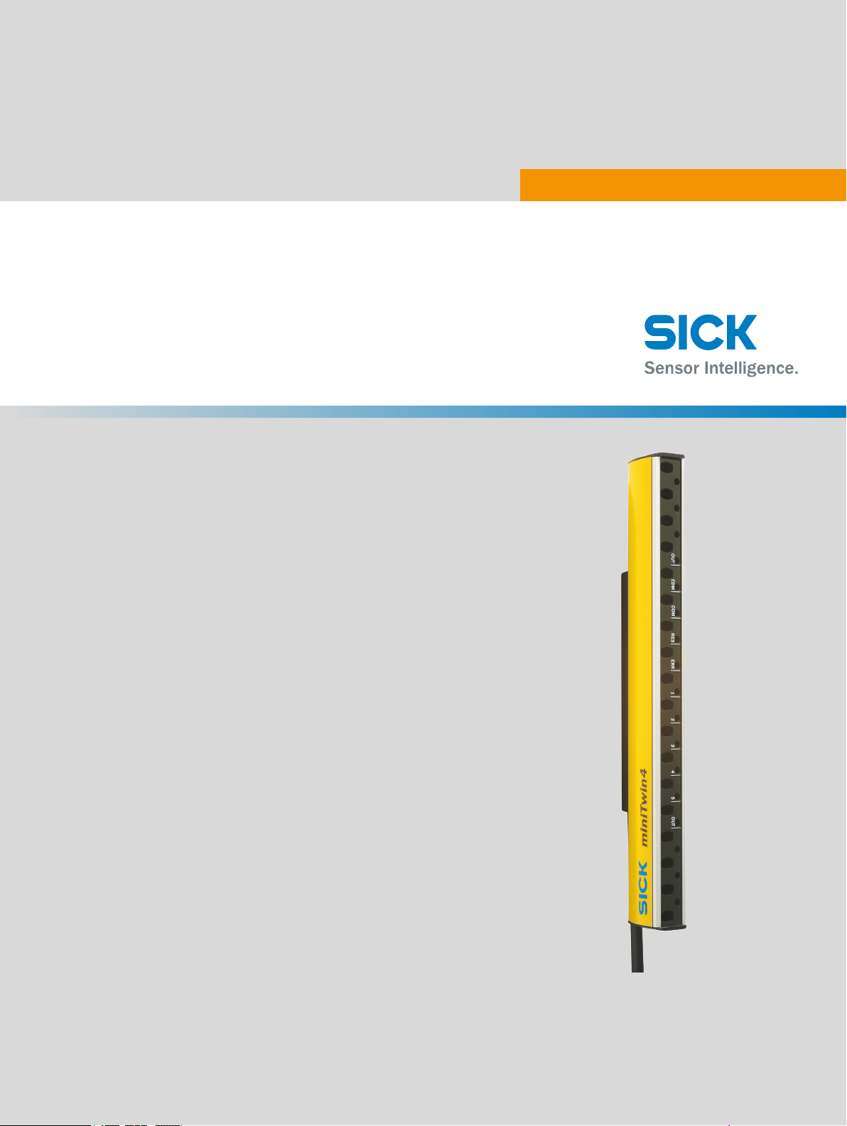
miniTwin4
Safety light curtain
O P E R A T I N G I N S T R U C T I O N S
Page 2
Described product
mini
Twin4
Manufacturer
SICK AG
Erwin-Sick-Str. 1
79183 Waldkirch
Germany
Legal information
his work is protected by copyright. Any rights derived from the copyright shall be
T
reserved for SICK AG. Reproduction of this document or parts of this document is only
permissible within the limits of the legal determination of Copyright Law. Any modifica‐
tion, abridgment or translation of this document is prohibited without the express writ‐
ten permission of SICK AG.
The trademarks stated in this document are the property of their respective owner.
© SICK AG. All rights reserved.
Original document
T
his document is an original document of SICK AG.
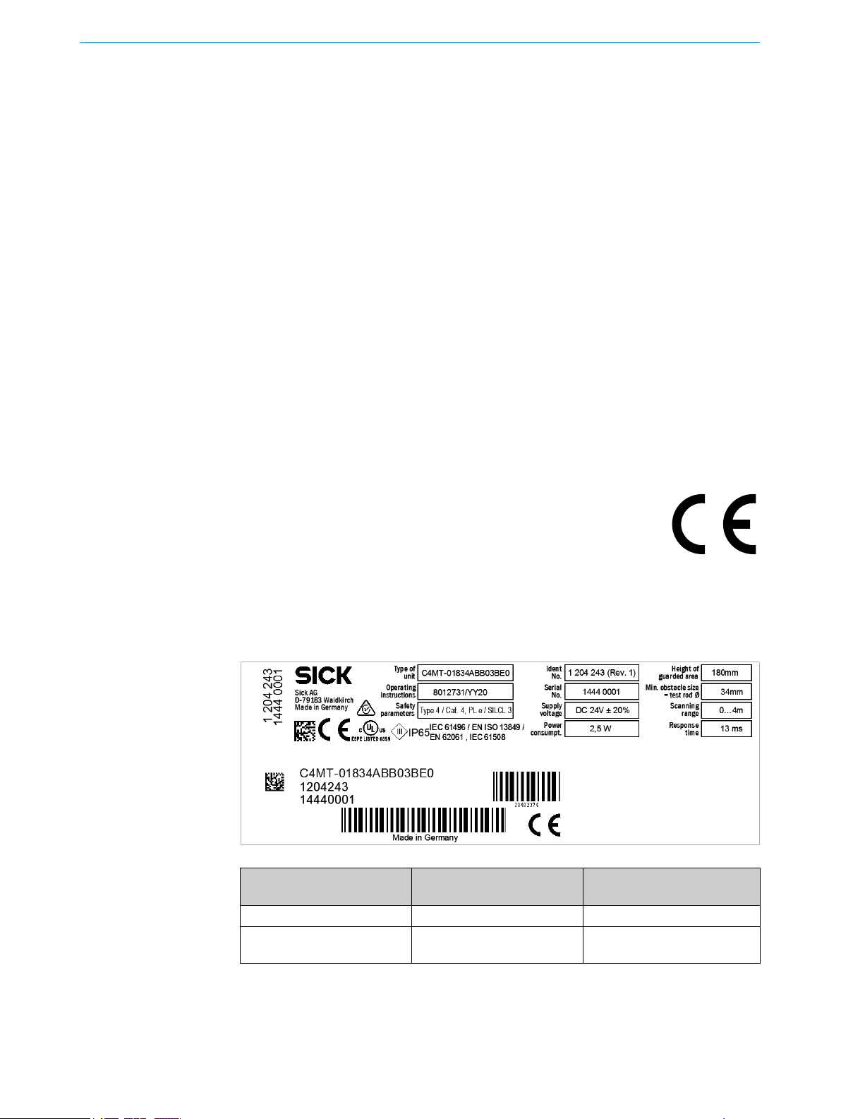
Change history of the device
T
he table below describes the technical changes made to the device in the course of
product maintenance. The change history of the device can be seen on the type label in
the Ident No. field with the additional change number “(Rev. #)”.
Change number in Ident No.
f
ield
No change number Initial device version
(Rev. 1) Addition to the Cross-circuit
Change Additional information
see "Structure and function",
monit
oring field
page 11
2
O PE R AT I NG IN S TR U CT I ON S | miniTwin4 8012624/10OM/2018-08-09 | SICK
Subject to change without notice
Page 3

Contents
CONTENTS
1 About this document........................................................................ 6
1.1 Scope......................................................................................................... 6
1.2 Target groups and structure of these operating instructions................ 6
1.3 Additional information.............................................................................. 7
1.4 Symbols and document conventions...................................................... 7
2 Safety information............................................................................ 9
2.1 General safety notes................................................................................ 9
2.2 Intended use............................................................................................. 9
2.3 Requirements for the qualification of personnel.................................... 10
3 Product description........................................................................... 11
3.1 Structure and function............................................................................. 11
3.2 Product characteristics............................................................................ 13
3.2.1 Device overview....................................................................... 13
3.2.2 Absence of blind zones........................................................... 14
3.2.3 Beam coding............................................................................ 14
3.2.4 Restart interlock...................................................................... 14
3.2.5 External device monitoring (EDM).......................................... 14
3.2.6 Cascading................................................................................. 15
3.2.7 System plug.............................................................................. 15
3.2.8 Flexible control cabinet cabling and status indication on
th sides................................................................................. 16
bo
3.2.9 Status indicators...................................................................... 17
3.3 Example applications............................................................................... 19
4 Project planning................................................................................ 21
4.1 Manufacturer of the machine.................................................................. 21
4.2 Operator of the machine.......................................................................... 21
4.3 Design........................................................................................................ 21
4.3.1 Scanning range and protective field width............................. 22
4.3.2 Minimum distance from the hazardous point....................... 23
4.3.3 Minimum distance from reflective surfaces.......................... 25
4.3.4 Minimum distance for cascaded systems............................. 26
4.3.5 Protection against interference from systems in close prox‐
imity to each other................................................................... 28
4.4 Integrating the equipment into the electrical control............................. 29
4.4.1 Protective operation without reset and/or without EDM...... 31
4.4.2 Restart interlock...................................................................... 32
4.4.3 External device monitoring (EDM).......................................... 34
4.4.4 Cascading................................................................................. 35
4.4.5 Connection diagrams.............................................................. 38
4.5 Testing plan............................................................................................... 40
4.5.1 Test rod check.......................................................................... 41
8012624/10OM/2018-08-09 | SICK O PE R AT I NG IN S TR U CT I ON S | miniTwin4
Subject to change without notice
3
Page 4

CONTENTS
4.5.2 Visual check of the machine and the protective device........ 43
5 Mounting............................................................................................. 44
5.1 Safety......................................................................................................... 44
5.2 Unpacking.................................................................................................. 44
5.3 Mounting the system plug........................................................................ 45
5.4 Mounting................................................................................................... 47
5.4.1 Mounting direction of the twin stick....................................... 49
5.4.2 Mounting options..................................................................... 49
5.4.3 Mounting with O-Fix bracket................................................... 50
5.4.4 Mounting with C-Fix bracket.................................................... 52
5.4.5 Mounting with L-Fix bracket..................................................... 53
5.4.6 Mounting with C-Fix bracket and L-Fix bracket...................... 55
5.4.7 Mounting with C-Fix-Flex bracket............................................ 56
5.5 Resolution at the end of the twin sticks.................................................. 58
6 Electrical installation........................................................................ 60
6.1 Safety......................................................................................................... 60
6.2 System connection................................................................................... 62
7 Configuration..................................................................................... 63
7.1 Factory settings......................................................................................... 63
7.1.1 Changing the configuration later............................................ 63
7.2 Configuring beam coding......................................................................... 63
7.3 Reset and external device monitoring (EDM)......................................... 64
7.3.1 Configuring reset..................................................................... 64
7.3.2 Configuring external device monitoring (EDM)...................... 65
7.3.3 Deactivating reset and EDM................................................... 66
7.4 Cascading.................................................................................................. 68
7.4.1 Cascading new devices........................................................... 71
7.4.2 Connecting a new device in an existing cascade.................. 71
7.4.3 Cascading pre-configured devices.......................................... 72
7.5 Status indication on both sides............................................................... 72
8 Commissioning.................................................................................. 73
8.1 Safety......................................................................................................... 73
8.2 Overview.................................................................................................... 73
8.3 When it is switched on.............................................................................. 74
8.4 Alignment of the twin stick....................................................................... 74
8.4.1 Aligning the twin sticks to one another.................................. 75
8.4.2 Indication of the alignment quality......................................... 77
8.5 Check during commissioning and modifications.................................... 77
9 Operation............................................................................................ 78
9.1 Safety......................................................................................................... 78
9.2 Regular thorough check........................................................................... 78
9.3 LEDs........................................................................................................... 79
4
O PE R AT I NG IN S TR U CT I ON S | miniTwin4 8012624/10OM/2018-08-09 | SICK
Subject to change without notice
Page 5

CONTENTS
10 Maintenance...................................................................................... 81
10.1 Safety......................................................................................................... 81
10.2 Regular cleaning....................................................................................... 81
10.3 Regular thorough check........................................................................... 82
11 Troubleshooting................................................................................. 83
11.1 Safety......................................................................................................... 83
11.2 Diagnostic LEDs........................................................................................ 83
11.2.1 Indications when switching on................................................ 83
11.2.2 Status indicator........................................................................ 85
11.2.3 Fault indicators........................................................................ 86
12 Decommissioning............................................................................. 88
12.1 Protection of the environment................................................................. 88
12.2 Disposal..................................................................................................... 88
13 Technical data.................................................................................... 89
13.1 Data sheet................................................................................................. 89
13.2 Response time.......................................................................................... 91
13.3 Power consumption.................................................................................. 92
13.4 Table of weights........................................................................................ 92
13.5 Dimensional drawings.............................................................................. 94
14 Ordering information........................................................................ 95
14.1 Scope of delivery....................................................................................... 95
14.2 Ordering information miniTwin4............................................................... 95
14.3 Weld spark guard...................................................................................... 99
14.4 Alignment aid............................................................................................ 100
15 Accessories........................................................................................ 101
15.1 Brackets.................................................................................................... 101
15.2 Connectivity............................................................................................... 102
15.3 Deflector mirrors....................................................................................... 104
15.3.1 Change in scanning range using deflector mirrors................ 104
15.3.2 PNS75 deflector mirror........................................................... 104
15.3.3 PNS125 deflector mirror......................................................... 105
16 Annex.................................................................................................. 106
16.1 Compliance with EU directives................................................................. 106
16.2 Checklist for initial commissioning and commissioning........................ 107
17 List of figures..................................................................................... 108
18 List of tables....................................................................................... 110
8012624/10OM/2018-08-09 | SICK O PE R AT I NG IN S TR U CT I ON S | miniTwin4
Subject to change without notice
5
Page 6

1 ABOUT THIS DOCUMENT
1 About this document
These operating instructions contain information required during the life cycle of the
afety light curtain.
s
These operating instructions are available to all those who work with the safety light
curtain.
Please read these operating instructions carefully and make sure that you understand
the content fully before working with the safety light curtain.
1.1 Scope
These operating instructions only apply to the miniTwin4 safety light curtain with one of
t
he following type label entries in the “Operating Instructions” field:
8012731
•
8012731/V114
•
8012731/YY20
•
8012731/YT85
•
This document is included with the following SICK part numbers (this document in all
available language versions):
8012731
1.2 Target groups and structure of these operating instructions
These operating instructions are intended for the following target groups: Project devel‐
oper
s (planners, developers, designers), installers, electricians, safety experts (e.g., CE
authorized representatives, compliance officers, persons who test and approve the
application), operators, and maintenance personnel.
The structure of these operating instructions is based on the life cycle phases of the
safety light curtain: Project planning, mounting, electrical installation, commissioning,
operation, and maintenance.
In many applications, the target groups are assigned as follows to the manufacturer
and the organization operating the machine in which the safety light curtain is inte‐
grated:
Area of responsibility Target group Specific chapters of these operating instruc‐
Manufacturer Project developers
(planners, developers,
designers)
Installers "Mounting", page 44
Electricians "Electrical installation", page 60
Safety experts "Project planning", page 21
1)
tions
"Project planning", page 21
"Configuration", page 63
"Technical data", page 89
"Accessories", page 101
onfiguration", page 63
"C
"Commissioning", page 73
"Technical data", page 89
"Checklist for initial commissioning and com‐
missioning", page 107
6
O PE R AT I NG IN S TR U CT I ON S | miniTwin4 8012624/10OM/2018-08-09 | SICK
Subject to change without notice
Page 7
ABOUT THIS DOCUMENT 1
Area of responsibility Target group Specific chapters of these operating instruc‐
Operating entity Operators "Operation", page 78
1)
Chapters not listed here are intended for all target groups. All target groups must follow all of the safety
and w
arning instructions in all chapters of the operating instructions!
In other applications, the operating organization is also the manufacturer of the equip‐
ment w
ith the corresponding allocation of the target groups.
1.3 Additional information
www.sick.com
T
he following information is available on the Internet:
This document in other languages
•
Data sheets and application examples
•
CAD data of drawings and dimensional drawings
•
Certificates (e.g. EU declaration of conformity)
•
Guide for Safe Machinery Six steps to a safe machine
•
Maintenance person‐
l
ne
1)
t
ions
"Troubleshooting", page 83
"Maintenance", page 81
"Troubleshooting", page 83
"Ordering information", page 95
1.4 Symbols and document conventions
The following symbols and conventions are used in this document:
Safety notes and other notes
DANGER
Indic
ates a situation presenting imminent danger, which will lead to death or serious
injuries if not prevented.
WARNING
ates a situation presenting possible danger, which may lead to death or serious
Indic
injuries if not prevented.
CAUTION
ates a situation presenting possible danger, which may lead to moderate or minor
Indic
injuries if not prevented.
NOTICE
Indic
ates a situation presenting possible danger, which may lead to property damage if
not prevented.
NOTE
Indicates useful tips and recommendations.
Instructions to action
T
he arrow denotes instructions to action.
b
8012624/10OM/2018-08-09 | SICK O PE R AT I NG IN S TR U CT I ON S | miniTwin4
Subject to change without notice
7
Page 8

1 A
BOUT THIS DOCUMENT
1. The sequence of instructions for action is numbered.
2.
Follow the order in which the numbered instructions are given.
✓
The check mark denotes the result of an instruction.
LED symbols
These symbols indicate the status of an LED:
The LED is off.
o
The LED is flashing.
Ö
The LED is illuminated continuously.
O
Sender and receiver
T
hese symbols indicate the sender and receiver of the device:
The symbol indicates the sender.
s
The symbol indicates the receiver.
r
8
O PE R AT I NG IN S TR U CT I ON S | miniTwin4 8012624/10OM/2018-08-09 | SICK
Subject to change without notice
Page 9
2 Safety information
This chapter contains information on general safety for the safety light curtain.
e safety information about specific usage situations of the safety light curtain is
Mor
available in the respective chapters.
2.1 General safety notes
DANGER
H
azard due to lack of effectiveness of the protective device
In the case of non-compliance, it is possible that the dangerous state of the machine
may not be stopped or not stopped in a timely manner.
Please read this document carefully and make sure that you understand the con‐
b
tent fully before working with the device.
Follow all safety notes in this document.
b
2.2 Intended use
SAFETY INFORMATION 2
Overview
he miniTwin4 safety light curtain is an electro-sensitive protective device (ESPE) and is
T
suitable for the following applications:
Hazardous point protection
•
Access protection
•
Hazardous area protection
•
The miniTwin4 safety light curtain must only be used within the limits of the prescribed
pecified technical data and operating conditions at all times.
and s
Any instance of improper use, incorrect modification, or manipulation of the miniTwin4
safety light curtain shall void any warranty provided by SICK AG; furthermore, SICK AG
shall not accept any responsibility or liability for any resulting damage and consequen‐
tial damage.
Important information
DANGER
azard due to lack of effectiveness of the protective device
H
Persons and parts of the body to be protected may not be recognized in case of nonobservance.
The safety light curtain works as an indirect protective measure and cannot provide pro‐
tection from parts thrown out nor from emitted radiation. Transparent objects are not
detected.
Only use the safety light curtain as an indirect protective measure.
b
Reasonably foreseeable misuse
g others, the miniTwin4 safety light curtain is not suitable for the following appli‐
Amon
cations:
Outdoors
•
Underwater
•
In explosion-hazardous areas
•
In environments with increased levels of ionizing radiation
•
8012624/10OM/2018-08-09 | SICK O PE R AT I NG IN S TR U CT I ON S | miniTwin4
Subject to change without notice
9
Page 10

AFETY INFORMATION
2 S
2.3 Requirements for the qualification of personnel
The safety light curtain must be configured, installed, connected, commissioned and
viced only by qualified safety personnel.
ser
Project planning
For project planning, a person is considered competent when he/she has expertise and
experience in the selection and use of protective devices on machines and is familiar
with the relevant technical rules and national work safety regulations.
Mechanical mounting
For mechanical mounting, a person is considered competent when he/she has the
expertise and experience in the relevant field and is sufficiently familiar with the appli‐
cation of the protective device on the machine that he/she can assess its operational
safety status.
Electrical installation
For electrical installation, a person is considered competent when he/she has the
expertise and experience in the relevant field and is sufficiently familiar with the appli‐
cation of the protective device on the machine that he/she can assess its operational
safety status.
Configuration
For configuration, a person is considered competent when he/she has the expertise
and experience in the relevant field and is sufficiently familiar with the application of
the protective device on the machine that he/she can assess its work safety aspects.
Commissioning
For commissioning, a person is considered competent when he/she has the expertise
and experience in the relevant field and is sufficiently familiar with the application of
the protective device on the machine that he/she can assess its operational safety sta‐
tus.
Operation and maintenance
For operation and maintenance, a person is considered competent when he/she has
the expertise and experience in the relevant field and is sufficiently familiar with the
application of the protective device on the machine and has been instructed by the
machine operator in its operation.
An operator may clean the safety light curtain and carry out specific checks as
instructed.
Further topics
"Operation", page 78
•
"Regular cleaning", page 81
•
10
O PE R AT I NG IN S TR U CT I ON S | miniTwin4 8012624/10OM/2018-08-09 | SICK
Subject to change without notice
Page 11
3 Product description
s
s
r
r
! !
This chapter provides information on the operation of the safety light curtain and shows
xamples of its range of use.
e
3.1 Structure and function
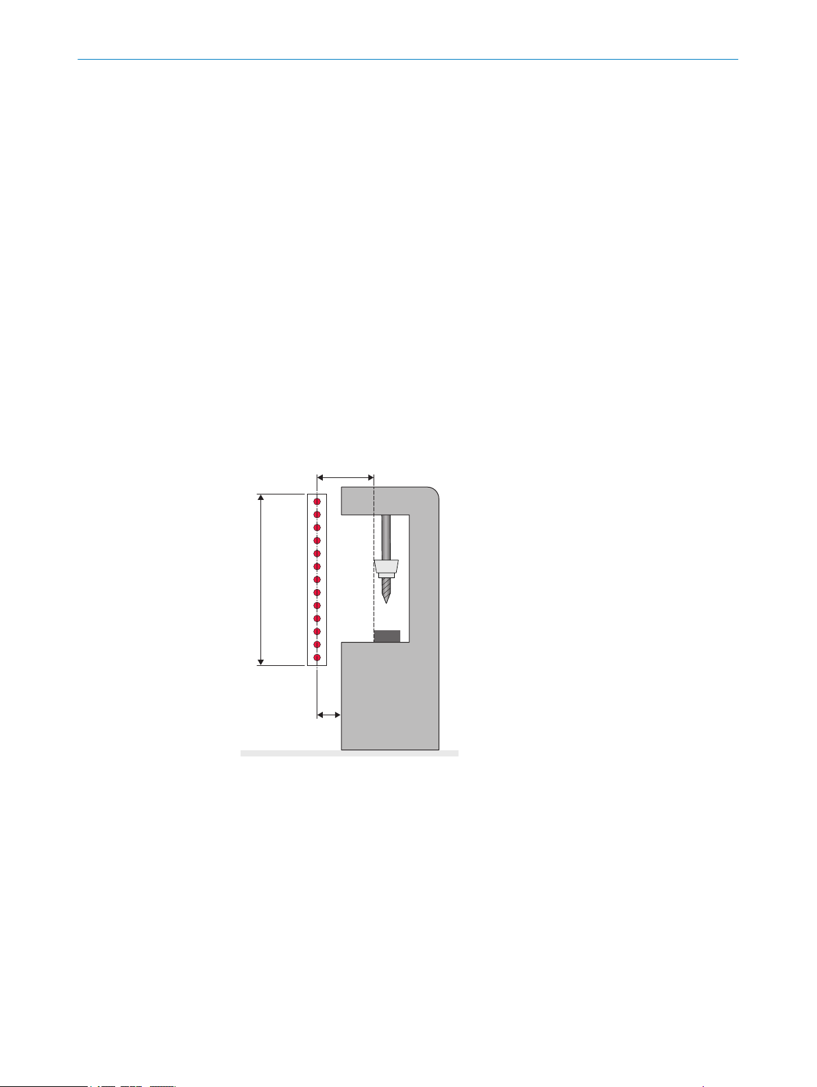
Overview
T
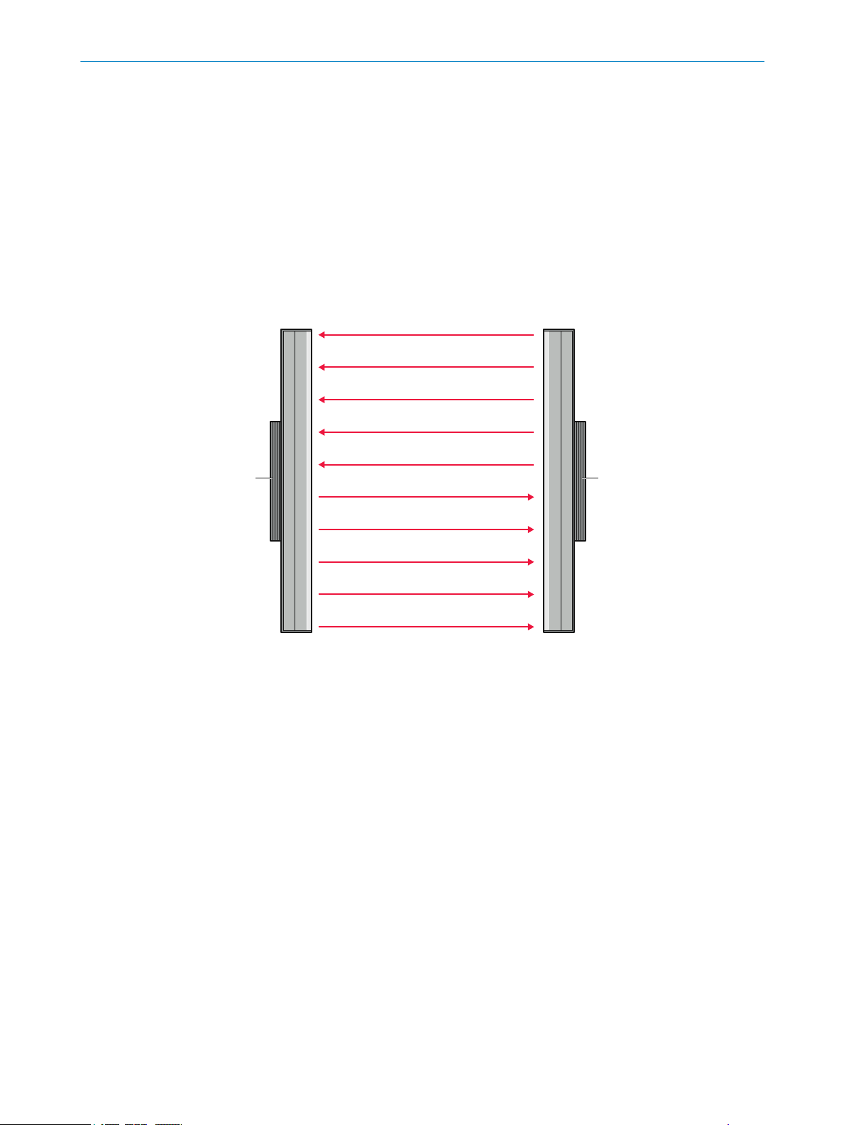
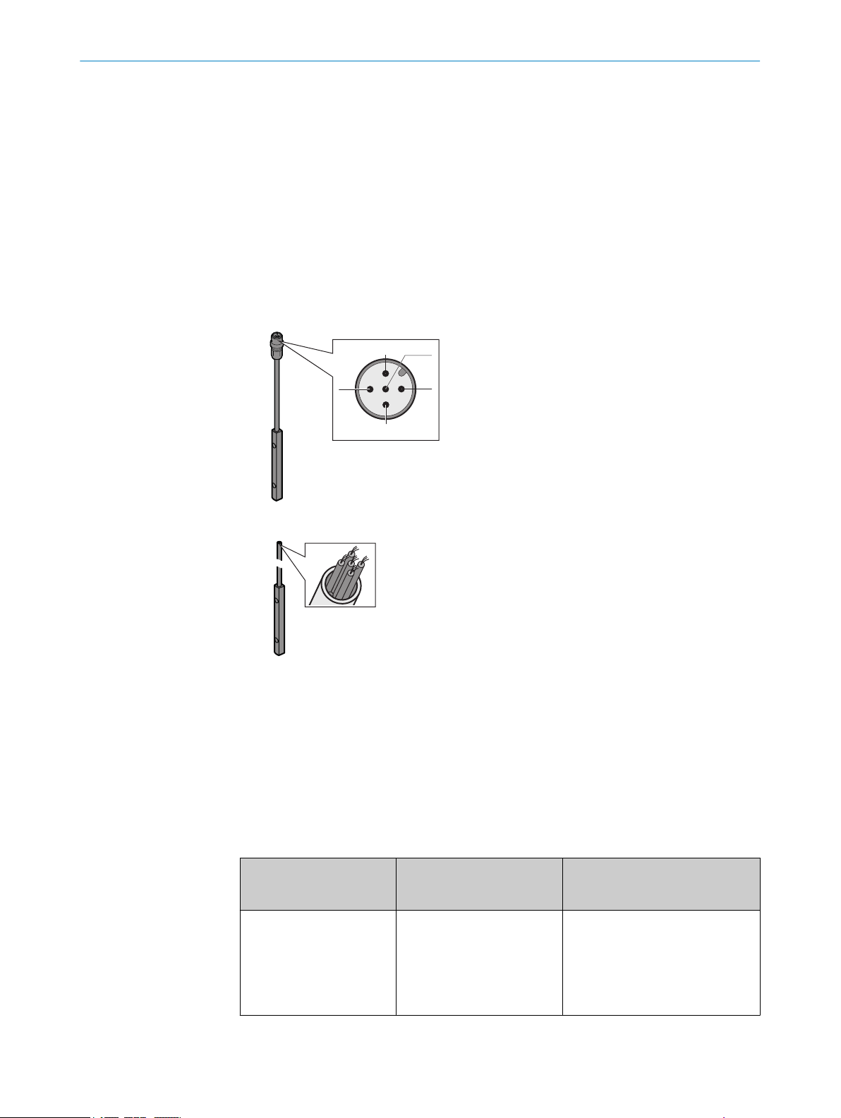
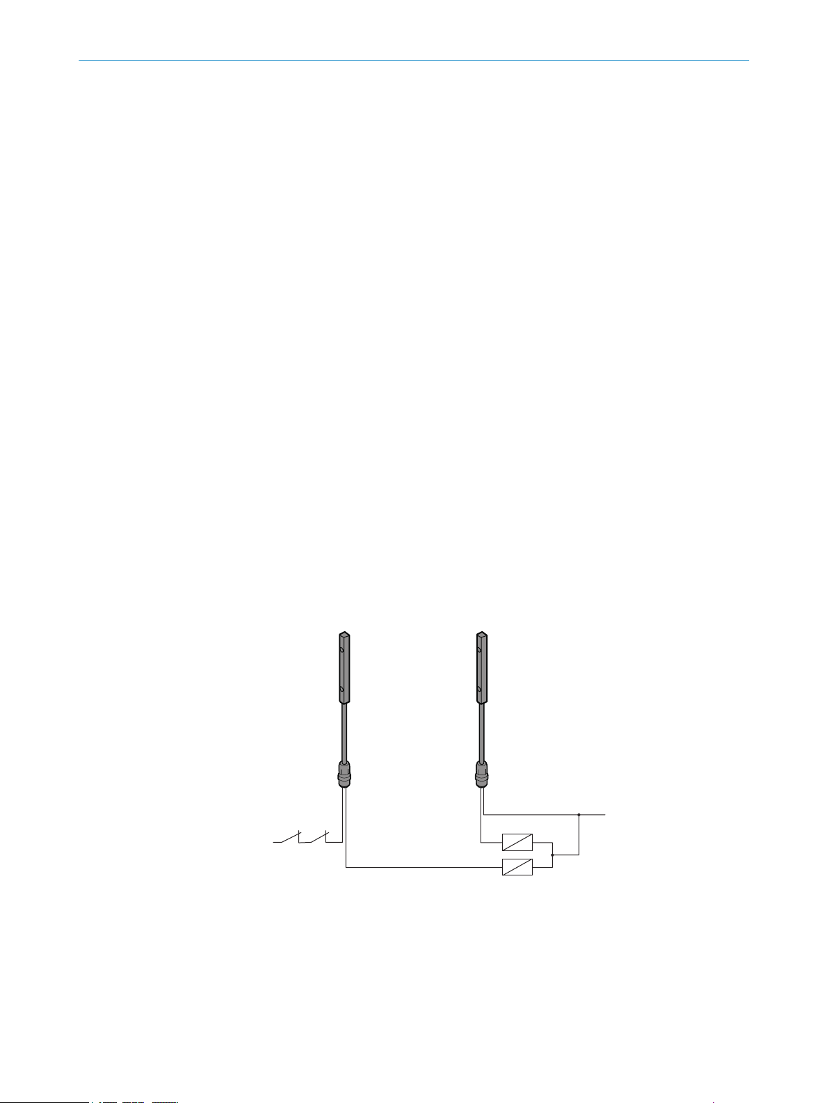
he miniTwin4 safety light curtain consists of 2 identical twin sticks. Each twin stick
contains both the sender as well as the receiver unit, see figure 1, page 11. The two
twin sticks are installed so that each sender and receiver unit are located opposite one
another.
PRODUCT DESCRIPTION 3
Figure 1: Device components of the safety light curtain
Twin stick
!
Safety light curtain principle
he protective field is between the two twin sticks and is defined by the protective field
T
height and the protective field width.
The two twin sticks automatically synchronize themselves optically. Each twin stick pro‐
vides an OSSD and a so-called multifunctional connection. The OSSDs are integrated
into the machine controller. Either a reset button or an EDM can be connected to the
multifunctional connections.
8012624/10OM/2018-08-09 | SICK O PE R AT I NG IN S TR U CT I ON S | miniTwin4
Subject to change without notice
11
Page 12
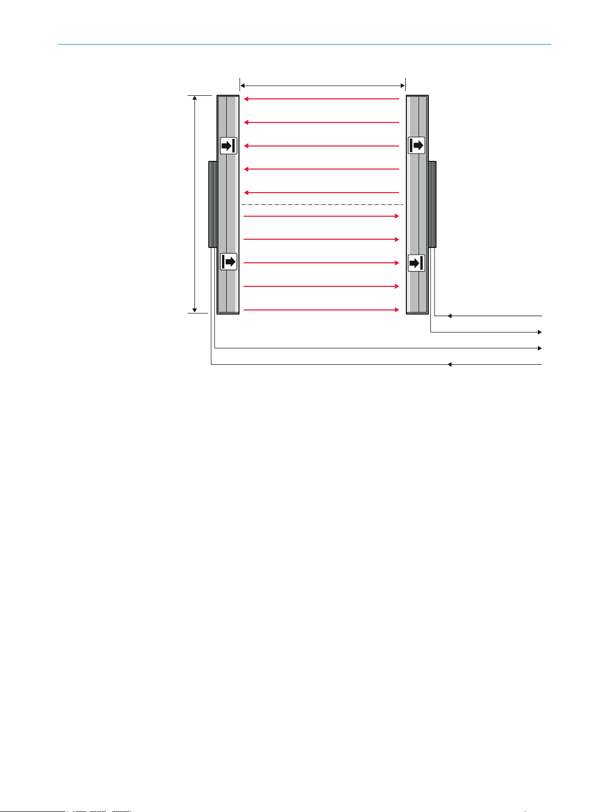
O
SSD2
O
SSD1
§
$
!
"
3 P
RODUCT DESCRIPTION
Figure 2: Safety light curtain principle
Protective field width
!
Protective field height
"
E.g. reset button
§
E.g. EDM
$
Protective field height
T
he protective field height indicates the range within which the test rod belonging to the
safety light curtain is reliably detected.
The size of the safety light curtain determines the protective field height.
Protective field width
T
he protective field width is the dimension of the light path between the twin sticks. The
maximum protective field width is limited by the scanning range.
Resolution
The resolution describes the size of the smallest object detected by the safety light cur‐
tain in the protective field. The resolution corresponds to the diameter of the test rod
belonging to the safety light curtain.
With the appropriate resolution, the safety light curtain provides finger and hand protec‐
tion.
12
Scanning range
The scanning range is the maximum protective field width. It is subject to the resolution
variant (14 mm or 30 mm).
The scanning range is reduced by the use of deflector mirrors and/or a weld spark
guard.
O PE R AT I NG IN S TR U CT I ON S | miniTwin4 8012624/10OM/2018-08-09 | SICK
Subject to change without notice
Page 13
!
"
§
PRODUCT DESCRIPTION 3
Cross-circuit monitoring
T
he following prerequisites apply for cross-circuit monitoring:
Cross-circuit monitoring is only done for devices which have a supplementary
•
change number “(Rev. no.)” on the type label in the Ident No. field.
When combining several devices, all devices must have a supplementary change
•
number “(Rev. no.)” on the type label in the Ident No. field, otherwise cross-circuit
monitoring is not provided.
Prerequisites for the protective function of the safety light curtain miniTwin4
he miniTwin4 safety light curtain can only fulfill its protective function when the follow‐
T
ing requirements are satisfied:
It must be possible to electrically influence the control of the machine.
•
It must be possible to change the dangerous state of the machine into a safe
•
state.
The miniTwin4 safety light curtain must be arranged so that objects are reliably
•
detected upon entry into the hazardous area.
The reset button must be mounted outside of the hazardous area so that it cannot
•
be actuated by a person who is inside the hazardous area. In addition, the opera‐
tor must have a complete overview of the hazardous area when actuating the reset
button.
When setting up and using the devices, the applicable statutory and regulatory
•
requirements must be observed.
Further topics
ata sheet", page 89
"D
•
"Deflector mirrors", page 104
•
"Weld spark guard", page 99
•
"Technical data", page 89
•
"Dimensional drawings", page 94
•
3.2 Product characteristics
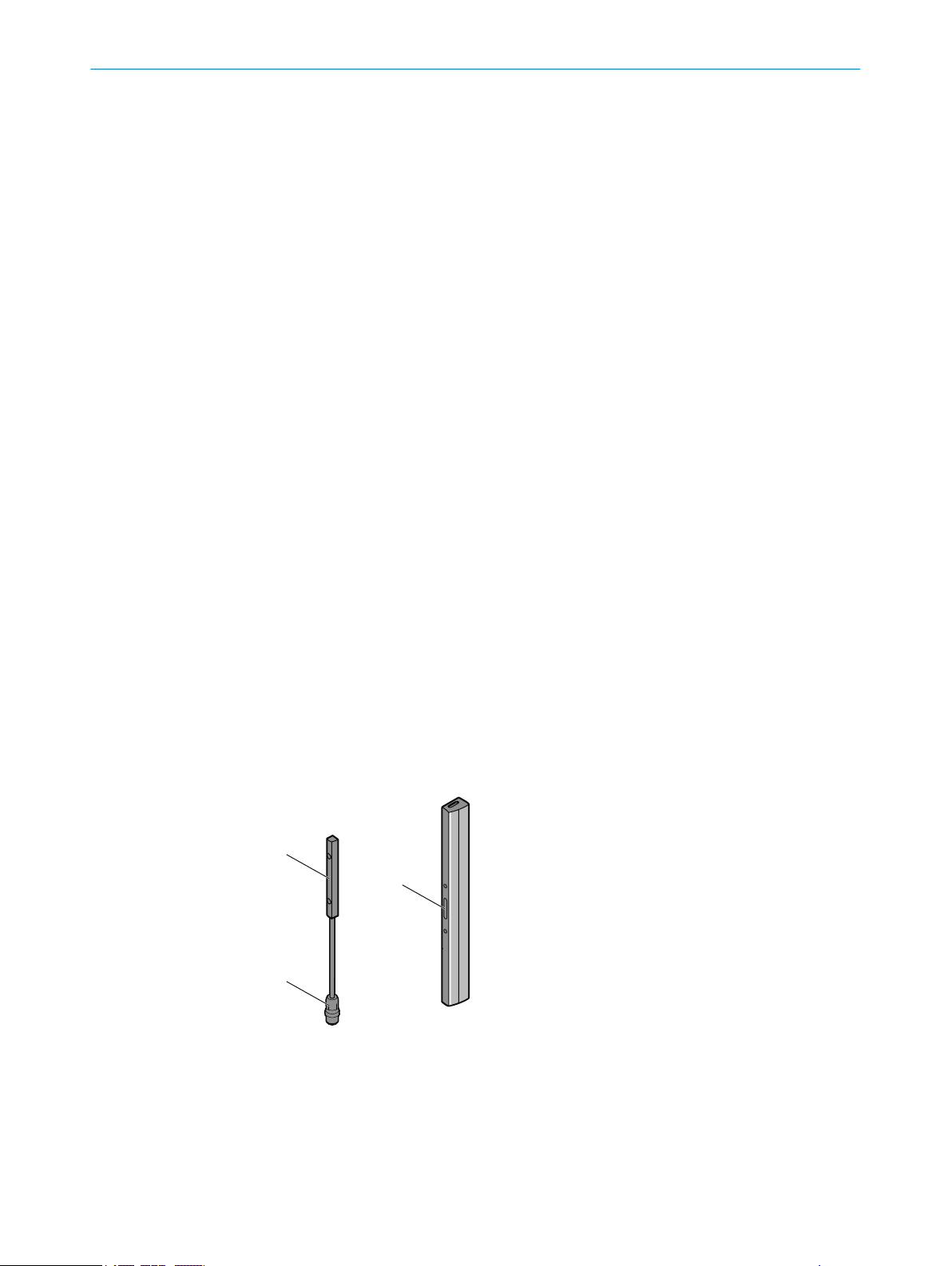
3.2.1 Device overview
Figure 3: Device with system plug and system connection
System plug
!
System connection
"
Device connection
§
8012624/10OM/2018-08-09 | SICK O PE R AT I NG IN S TR U CT I ON S | miniTwin4
Subject to change without notice
13
Page 14
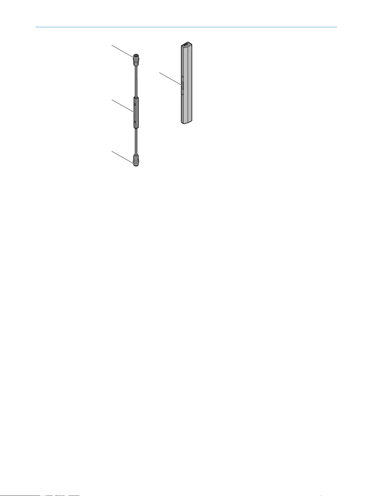
!
$
"
§
3 P
RODUCT DESCRIPTION
Figure 4: Device with system plug and system connection and one extension connection
Extension connection
!
System plug
"
System connection
§
Device connection
$
3.2.2 Absence of blind zones
The design and construction of the safety light curtain extends the protective function
t
o the end of the housing without any blind spots. The absence of blind zones reduces
the space requirement when integrated in the machine.
3.2.3 Beam coding
Depending on its configuration, the safety light curtain operates with 1 of 2 beam cod‐
in
gs: code 1 or code 2. In order to avoid mutual interference between 2 neighboring
safety light curtains, one can be operated with code 1 and the other with code 2.
3.2.4 Restart interlock
The safety light curtain has an integrated restart interlock. The function can be config‐
ur
ed during commissioning.
A restart interlock prevents the machine from starting again once the protective device
has been triggered. First, the operator must press a reset pushbutton to return the pro‐
tective device to monitoring status. Then, in a second step, the operator can restart the
machine.
The reset pushbutton can be connected locally to the extension connection or in the
control cabinet.
3.2.5 External device monitoring (EDM)
The safety light curtain has integrated external device monitoring. The function can be
c
onfigured during commissioning.
14
The external device monitoring (EDM) monitors the status of downstream contactors.
In order to use the external device monitoring, positively guided contactors must be
used to switch off the machine. If the auxiliary contacts of the positively guided contac‐
tors are connected to the external device monitoring, the external device monitoring
checks whether the contactors drop off when the OSSDs are switched off.
O PE R AT I NG IN S TR U CT I ON S | miniTwin4 8012624/10OM/2018-08-09 | SICK
Subject to change without notice
Page 15
3.2.6 Cascading
FE
2
3
1
4
PRODUCT DESCRIPTION 3
3.2.7 System plug
Cascading allows up to 3 safety light curtains to be connected in series, e.g. f
or reliable
presence detection. The device connected to the control cabinet is the host device. The
subsequent sensors are called guest 1 and guest 2.
Overview
T
he safety light curtain requires a system plug.
The system plug is available in the following variants:
System plug with 5-pin system connection (M12×4 + FE male connector)
•
System plug with one 5-pin system connection (M12×4 + FE male connector) and
•
one 5-pin extension connection (M12×4 + FE female connector)
Figure 5: System connection pin assignment
Figure 6: System connection wires
Pre-assembled cables with open ends are available for connecting applications.
Functions of the safety light curtain
he following functions are available depending on the system plug used:
T
Restart interlock
•
External device monitoring (EDM)
•
Cascading
•
Table 1: Use of system plugs in a single system and in a cascade
System plug with 5-pin sys‐
em connection
t
Single system
8012624/10OM/2018-08-09 | SICK O PE R AT I NG IN S TR U CT I ON S | miniTwin4
Subject to change without notice
✓
w
ithout additional func‐
•
tion
RES or EDM can option‐
•
ally be configured on a
twin stick
System plug with 5-pin system
connection and 5-pin extension
connection
–
15
Page 16

3 P
RODUCT DESCRIPTION
System plug with 5-pin sys‐
t
em connection
Host of a cascade –
First guest of a cascade
for cascade with 2 guest
(
devices)
Last guest of a cascade
✓
System plug suitable.
–
System plug not suitable.
–
✓
no addit
•
on the device
ional function
Further topics
"R
estart interlock", page 14
•
"External device monitoring (EDM)", page 14
•
"Cascading", page 15
•
"Connectivity", page 102
•
"Test rod check", page 41
•
3.2.8 Flexible control cabinet cabling and status indication on both sides
System plug with 5-pin system
connection and 5-pin extension
connection
✓
R
ES or EDM can optionally be
•
configured on a twin stick
✓
–
•
no addit
device
ional function on the
The safety light curtain can be connected to the control cabinet via separate connec‐
t
ion cables for each twin stick.
In a cascade, only the twin sticks of the host are connected to the control cabinet.
The OSSD status and the status of the protective field are indicated via LEDs, if applica‐
ble, the configured RES or EDM additional function is as well.
Further topics
"C
onnection diagrams", page 38
•
16
O PE R AT I NG IN S TR U CT I ON S | miniTwin4 8012624/10OM/2018-08-09 | SICK
Subject to change without notice
Page 17

3.2.9 Status indicators
!
!
!
!
!
!
!
!
180 mm
300 mm
120 mm
240 mm
&
"
§
$
%
PRODUCT DESCRIPTION 3
Figure 7: LEDs on the twin sticks
!
"
§
$
%
&
OUT
EDM
COM
RES
ERR
1, 2, 3, 4, 5
figure 7 sho
ular intervals above a protective field height of 180 mm and can light up red or green. It
is only labeled OUT in two locations on the safety light curtain.
ws the LEDs of the safety light curtain. The OUT LED (!) is mounted at reg‐
Lit up LEDs indicate a specific status of the safety light curtain. Flashing LEDs demand
action.
8012624/10OM/2018-08-09 | SICK O PE R AT I NG IN S TR U CT I ON S | miniTwin4
Subject to change without notice
17
Page 18

3 P
RODUCT DESCRIPTION
Table 2: Meaning of LEDs
Position LED Display Comment
!
"
§
$
%
&
OUT
EDM
COM
RES
ERR
1, 2, 3, 4, 5
O Gr
een
O Red
O Or
ange
Ö Or
ange
hite
O W
Ö W
hite
O Or
ange
Ö Or
ange
O Red
Ö R
ed
O Blue
Ö Blue In combination with ERR-LED Ö r
LED lights up green when protective field is free
SSD on).
(O
LED lights up red when protective field is inter‐
rupted (OSSD off).
External device monitoring configured.
For the configuration of EDM at the first OSSD sta‐
us change, the safety light curtain expects the
t
change from 24 V to 0 V at the multifunctional
input.
Or:
In combination with the ERR-LED Ö red: External
device monitoring reports defective contactor
External communication active (e.g. for service)
No optical communication to another twin stick .
Or:
eedback when deactivating configuration.
F
Reset configured.
Reset configured.
Or:
In combina
Ö orange: error with configuration or cabling.
Protective field interrupted.
Error.
Indication of the alignment quality.
error.
tion with ERR-LED Ö red and EDM-LED
ed: display of an
o LED of
f. Ö LED flashes. O LED illuminates.
Further topics
"Dia
•
•
•
gnostic LEDs", page 83
"Status indicators", page 17
"Aligning the twin sticks to one another", page 75
18
O PE R AT I NG IN S TR U CT I ON S | miniTwin4 8012624/10OM/2018-08-09 | SICK
Subject to change without notice
Page 19
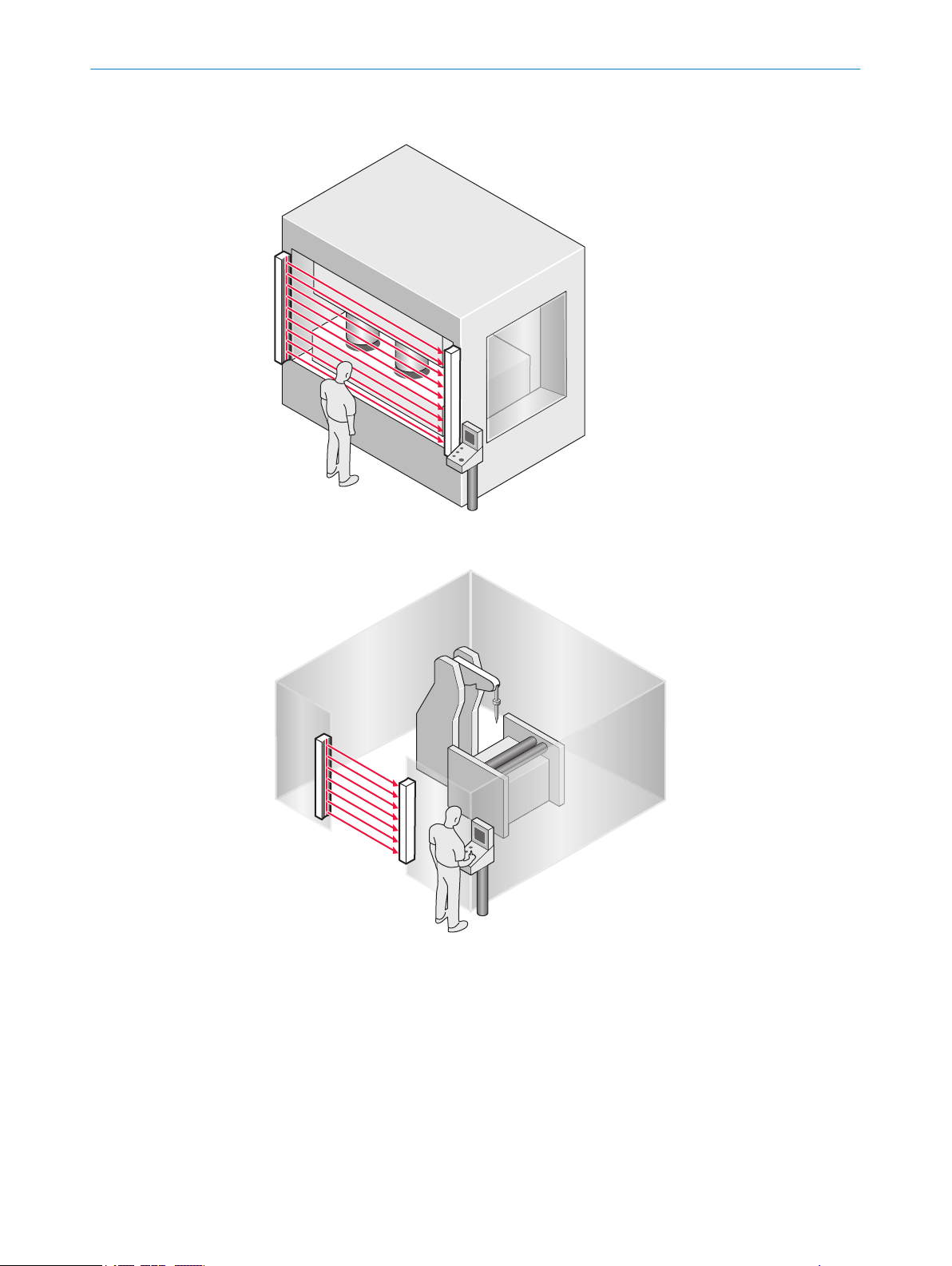
3.3 Example applications
PRODUCT DESCRIPTION 3
Figure 8: Hazardous point protection
Figure 9: Access protection
8012624/10OM/2018-08-09 | SICK O PE R AT I NG IN S TR U CT I ON S | miniTwin4
Subject to change without notice
19
Page 20
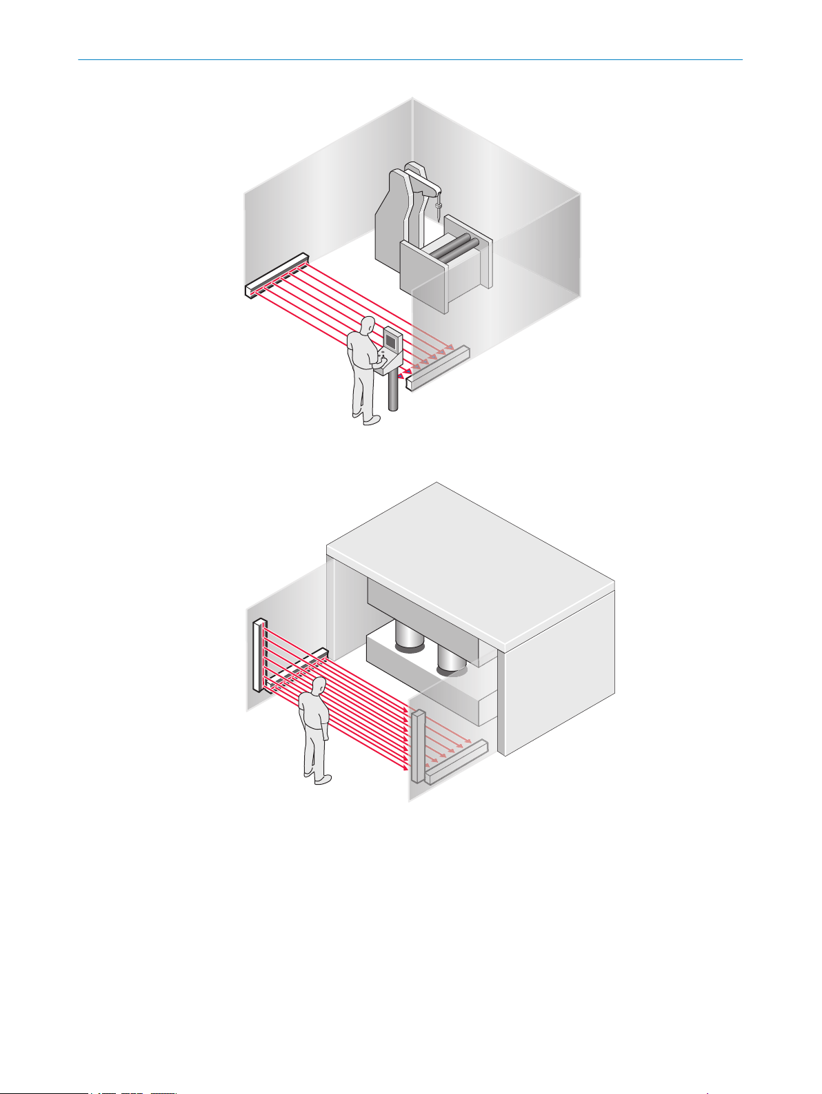
3 PRODUCT DESCRIPTION
Figure 10: Hazardous area protection
Figure 11: Access protection with presence detection, implemented by cascade
20
O PE R AT I NG IN S TR U CT I ON S | miniTwin4 8012624/10OM/2018-08-09 | SICK
Subject to change without notice
Page 21

4 Project planning
This chapter includes important information about the proper integration of the safety
ght curtain in machines for planners, developers and designers.
li
4.1 Manufacturer of the machine
DANGER
H
azard due to lack of effectiveness of the protective device
Persons and parts of the body to be protected may not be recognized in case of nonobservance.
Conduct a risk assessment and check whether additional protective measures are
b
required.
Comply with the applicable national regulations derived from the application (e.g.,
b
work safety regulations, safety rules, or other relevant safety guidelines).
Do not combine the components of the safety light curtain with components from
b
other safety light curtains.
Apart from for the procedures described in this document, the components of the
b
safety light curtain must not be opened.
The components of the safety light curtain must not be tampered with or changed.
b
Do not carry out any repairs on the device components. Improper repair of the pro‐
b
tective device can lead to a loss of the protective function.
PROJECT PLANNING 4
4.2 Operator of the machine
DANGER
H
azard due to lack of effectiveness of the protective device
Persons and parts of the body to be protected may not be recognized in case of nonobservance.
Changes to the electrical integration of the safety light curtain in the machine con‐
b
trol and changes to the mechanical installation of the safety light curtain require
another risk assessment. The results of this risk assessment may require the
operator of the machine to meet the obligations of a manufacturer.
Apart from the procedures described in this document, the components of the
b
safety light curtain must not be opened.
The components of the safety light curtain must not be tampered with or changed.
b
Do not carry out any repairs on the device components. Improper repair of the pro‐
b
tective device can lead to a loss of the protective function.
4.3 Design
Overview
T
his chapter contains important information about the design.
8012624/10OM/2018-08-09 | SICK O PE R AT I NG IN S TR U CT I ON S | miniTwin4
Subject to change without notice
21
Page 22
4 PROJECT PLANNING
Important information
DANGER
azard due to lack of effectiveness of the protective device
H
Persons and parts of the body to be protected may not be recognized in case of nonobservance.
Make sure that the following construction requirements are met so that the safety
b
light curtain can fulfill its protective function.
Twin sticks must be arranged such that persons or parts of the body are reli‐
°
ably detected when they enter the hazardous area.
Reaching under, over, and around as well as moving the safety light curtain
°
must be prevented.
Check whether additional safety measures (e.g. restart interlock) are neces‐
°
sary when it is possible for people to be located between the protective
device and the danger point without being detected.
DANGER
H
azard due to lack of effectiveness of the protective device
Certain types of light radiation can influence the protective device, e.g., light radiation
from fluorescent lamps with electronic ballast installed in the path of the beam, or
beams from laser pointers directed at the receiver unit of a twin stick.
If this type of light radiation is present in the environment of the protective device,
b
take additional measures to ensure that the protective device does not become
dangerous.
Further topics
"Mount
•
4.3.1 Scanning range and protective field width
Important information
DANGER
Hazard due to lack of effectiveness of the protective device
Persons and parts of the body to be protected may not be recognized in case of nonobservance.
The safety light curtain can only be mounted on machines on which the protective
b
field width does not change when the safety light curtain is switched on.
Scanning range
he scanning range limits the maximum protective field width.
T
The scanning range is reduced by the use of deflector mirrors and/or a weld spark
guard.
ing", page 44
22
Protective field width
T
he protective field width is the dimension of the light path between the twin sticks of a
system.
O PE R AT I NG IN S TR U CT I ON S | miniTwin4 8012624/10OM/2018-08-09 | SICK
Subject to change without notice
Page 23

Further topics
"T
echnical data", page 89
•
"Deflector mirrors", page 104
•
"Weld spark guard", page 99
•
4.3.2 Minimum distance from the hazardous point
Overview
PROJECT PLANNING 4
A minimum dis
ardous point. This distance is required to prevent a person or part of their body from
reaching the hazardous point before the end of the machine’s dangerous state.
Calculating the minimum distance according to ISO 13855
The calculation of the minimum distance is based on international or national stan‐
dards and statutory requirements applicable at the place of installation of the machine.
If the minimum distance is calculated according to ISO 13855, it depends on the fol‐
lowing points:
Machine stopping time (time interval between triggering the sensor function and
•
the end of the machine’s dangerous state)
Response time of the protective device
•
Reach or approach speed of the person
•
Resolution (detection capability) of the safety light curtain
•
Type of approach: orthogonal (at right angles) or parallel
•
Parameters specified based on the application
•
For the USA (scope of OSHA and ANSI), different regulations may apply, e.g.:
a) Laws: Code of Federal Regulations, Title 29 (CFR 29), Part 1910.217
b) Standards: ANSI B11.19
Complementary information
A
dditional information is available in the ISO 13855 standard and in the Guide for Safe
Machinery.
tance must be maintained between the safety light curtain and the haz‐
SICK offers a stopping/run-down time measurement service in many countries.
Further topics
"R
esponse time", page 91
•
4.3.2.1 Calculating minimum distance from the hazardous point
Important information
DANGER
Minimum distance from the hazardous point is too small
The dangerous state of the machine may not be stopped or not be stopped in a timely
manner due to a minimum distance that is too small.
Calculate the minimum distances for the machine in which the safety light curtain
b
is integrated.
When mounting the safety light curtain, observe the minimum distance.
b
8012624/10OM/2018-08-09 | SICK O PE R AT I NG IN S TR U CT I ON S | miniTwin4
Subject to change without notice
23
Page 24
!
"
§
S
4 P
ROJECT PLANNING
Approach
T
he example shows the calculation of the minimum distance in accordance with ISO
13855 for an orthogonal (right-angled) approach to the protective field. A different cal‐
culation may be required depending on the application and the ambient conditions
(e.g., for a protective field parallel to or at any angle to the direction of approach or an
indirect approach).
1. First calculate S with the following formula:
S = 2,000 mm/s × T + 8 ×(d – 14 mm)
where:
S = minimum dis
°
T = machine stopping time + response time of the protective device after
°
interruption in the light path in seconds (s)
d = resolution of the safety light curtain in millimeters (mm)
°
The reach or approach speed is already included in the formula.
tance in millimeters (mm)
2. If the result S is ≤ 500 mm, then use the determined value as the minimum dis‐
ance.
t
3. If the result S is > 500 mm, then recalculate S as follows:
S = 1,600 mm/s × T + 8 ×(d – 14 mm)
4. If the new value S is > 500 mm, then use the newly determined value as the mini‐
mum distance.
5. If the new value S is ≤ 500 mm, then use 500 mm.
24
Figure 12: Minimum distance to hazardous point for orthogonal (right-angled) approach to pro‐
t
ective field
Protective field height
!
Hazardous point
"
Depending on the application and distance, persons must be prevented from standing
§
behind the protective device.
Example calculation
Mac
hine stopping time = 290 ms
Response time after interruption of the light path = 30 ms
Resolution of the safety light curtain = 14 mm
T = 290 ms + 30 ms = 320 ms = 0.32 s
S = 2,000 mm/s × 0.32 s + 8 × (14 mm – 14 mm) = 640 mm
O PE R AT I NG IN S TR U CT I ON S | miniTwin4 8012624/10OM/2018-08-09 | SICK
Subject to change without notice
Page 25
S > 500 mm, therefore:
rs
D
a
S = 1,600 mm/s × 0.32 s + 8 × (14 mm – 14 mm) = 512 mm
4.3.2.2 Taking reach over into account
In accordance with ISO 13855, it must not be possible to defeat the ESPE. If access to
t
he hazardous area by reaching over a protective field cannot be prevented, the height
of the protective field and minimum distance of the ESPE must be determined. This is
done by comparing the calculated values based on the possible detection of limbs or
body parts with the values resulting from reaching over the protective field. The greater
value resulting from this comparison must be used.
PROJECT PLANNING 4
Figure 13: Representation of the accessibility of electro-sensitive protective device by reaching
ver. Left: Protective field that cannot be reached over. Right: Protective field that can be reached
o
over.
4.3.3 Minimum distance from reflective surfaces
Overview
T
he light beams from the sender unit may be deflected by reflective surfaces and dis‐
persive media. This can prevent an object from being detected.
Therefore, all reflective surfaces and objects (e.g. material bins, machine table, etc.)
must maintain a minimum distance (a) from the protective field. This minimum dis‐
tance (a) must be maintained on all sides of the protective field. This applies in horizon‐
tal, vertical and diagonal directions as well as at the end of the safety light curtain. The
same area must be free of dispersive media (e.g., dust, fog, or smoke).
The minimum distance (a) depends on the distance (D) between the twin sticks (protec‐
tive field width).
The weld spark guard can influence the optical properties of the safety light curtain,
meaning that reflective surfaces have to observe a larger minimum distance.
Figure 14: Minimum distance from reflective surfaces
8012624/10OM/2018-08-09 | SICK O PE R AT I NG IN S TR U CT I ON S | miniTwin4
Subject to change without notice
25
Page 26
1000
900
800
700
600
14 16 18 20 22 242 4 6 8 10 12
500
400
300
200
100
0
0
D/m
a/mm
4 P
ROJECT PLANNING
Important information
DANGER
azard due to lack of effectiveness of the protective device
H
Reflective surfaces and dispersive media can prevent persons or parts of the body to
be protected from being properly reflected and, therefore, remain undetected.
Make sure that all reflective surfaces and objects maintain a minimum distance
b
from the protective field.
Make sure that no dispersive media (e.g., dust, fog, or smoke) are within the calcu‐
b
lated minimum distance from the protective field.
Determining minimum distance to reflective surfaces
T
he minimum distance can be determined as follows:
Determine the distance between the twin sticks D in meters (m).
b
Read the minimum distance a in millimeters (mm) in the graph or calculate it
b
based on the respective formula table 3:
Figure 15: Graph of minimum distance from reflective surfaces
T
able 3: Formula for calculating the minimum distance from reflective surfaces
Distance D between twin sticks in m Calculation of the minimum distance (a) from reflective
faces in mm
sur
D ≤ 3 m a = 131 mm
D > 3 m a = tan (2.5°) × 1000 mm/m × D = 43.66 × 1 mm/m ×
D
Further topics
eld spark guard", page 99
"W
•
4.3.4 Minimum distance for cascaded systems
Overview
In a c
ascade, the codes of the individual participants are automatically set to code 1 or
code 2 in alternation.
In a cascaded system with a protective field width of up to 3 m, a minimum distance of
262 mm between the host and guest 2 must be upheld during mounting.
26
O PE R AT I NG IN S TR U CT I ON S | miniTwin4 8012624/10OM/2018-08-09 | SICK
Subject to change without notice
Page 27
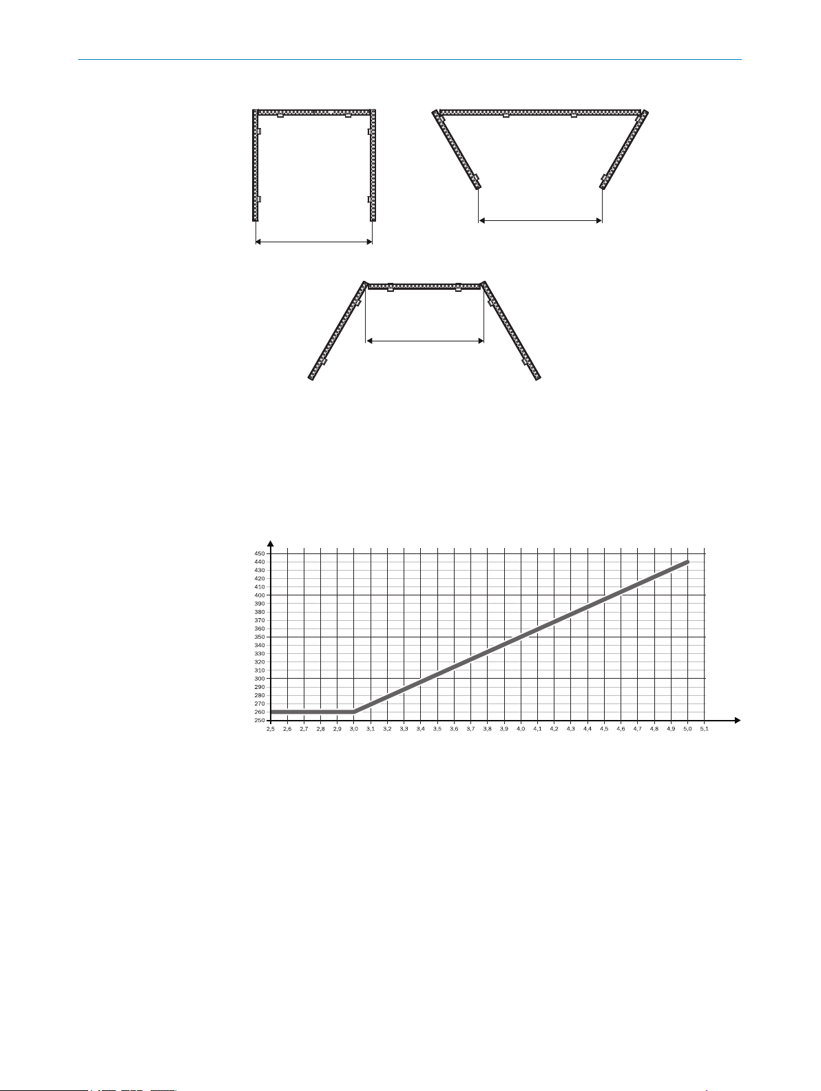
a min. 262
a min. 262
a min. 262
!
!
!
"
"
"
§ §
§
Figure 16: Minimum distance between host and guest 2 (mm)
a/mm
D/m
Guest 1
!
Guest 2
"
Host
§
PROJECT PLANNING 4
F
or protective field widths over 3 m, minimum distance a [mm] can be read in the
b
diagram:
Figure 17: Diagram minimum distance between host and guest 2
Or:
F
rom a 3 m protective field width, calculate the minimum distance with the follow‐
b
ing formula
a [mm] = tan 5° × D [m] × 1000
Example:
a = tan 5° × 4 m × 1000
a = 349.28 mm ~ 350 mm
8012624/10OM/2018-08-09 | SICK O PE R AT I NG IN S TR U CT I ON S | miniTwin4
Subject to change without notice
27
Page 28
s
rs
r
!
"
4 P
ROJECT PLANNING
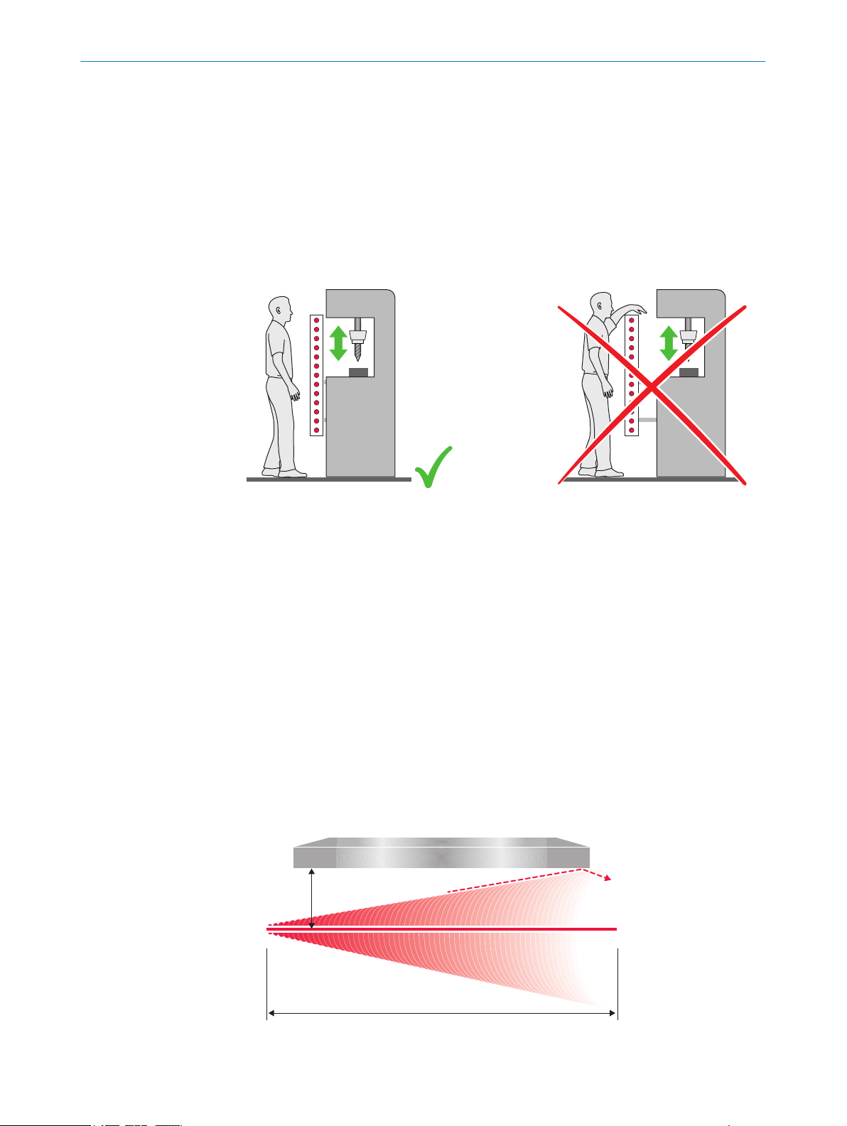
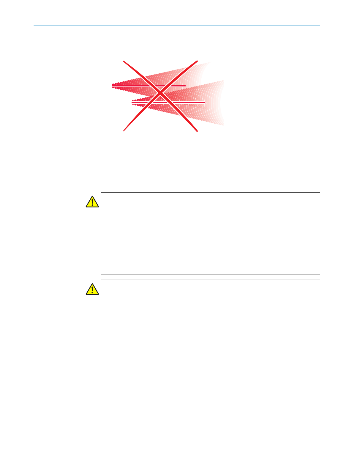
4.3.5 Protection against interference from systems in close proximity to each other
Overview
!
Figure 18: Preventing mutual interference from system
The infrared light beams of the sender unit of system ! can interfere with the receiver
unit of system ". This can disrupt the protective function of system ". This would
mean that the operator is at risk.
Important information
and system
"
DANGER
H
azard due to lack of effectiveness of the protective device
The external laser alignment aid may influence the receiver unit of a safety light curtain
in close proximity. In such cases, the neighboring safety light curtain may not detect
persons or parts of the body that require protection.
Perform an alignment or take other measures to ensure that the laser beam only
b
hits the front screen of the relevant twin stick. An external twin stick is a twin stick
that is not part of the same safety light curtain or same cascade.
During alignment in particular, make sure that the laser beam does not hit any
b
external twin stick.
DANGER
H
azard due to lack of effectiveness of the protective device
Systems of safety light curtains that operate in close proximity to each other can inter‐
fere with each other.
Use appropriate measures to prevent systems in close proximity from interfering
b
with each other.
Preventing interference between systems in close proximity to each other
he following measures prevent interference from systems in close proximity:
T
Different beam coding for neighboring systems
•
Optically opaque partitions
•
28
Further topics
"Using beam coding", page 29
•
O PE R AT I NG IN S TR U CT I ON S | miniTwin4 8012624/10OM/2018-08-09 | SICK
Subject to change without notice
Page 29
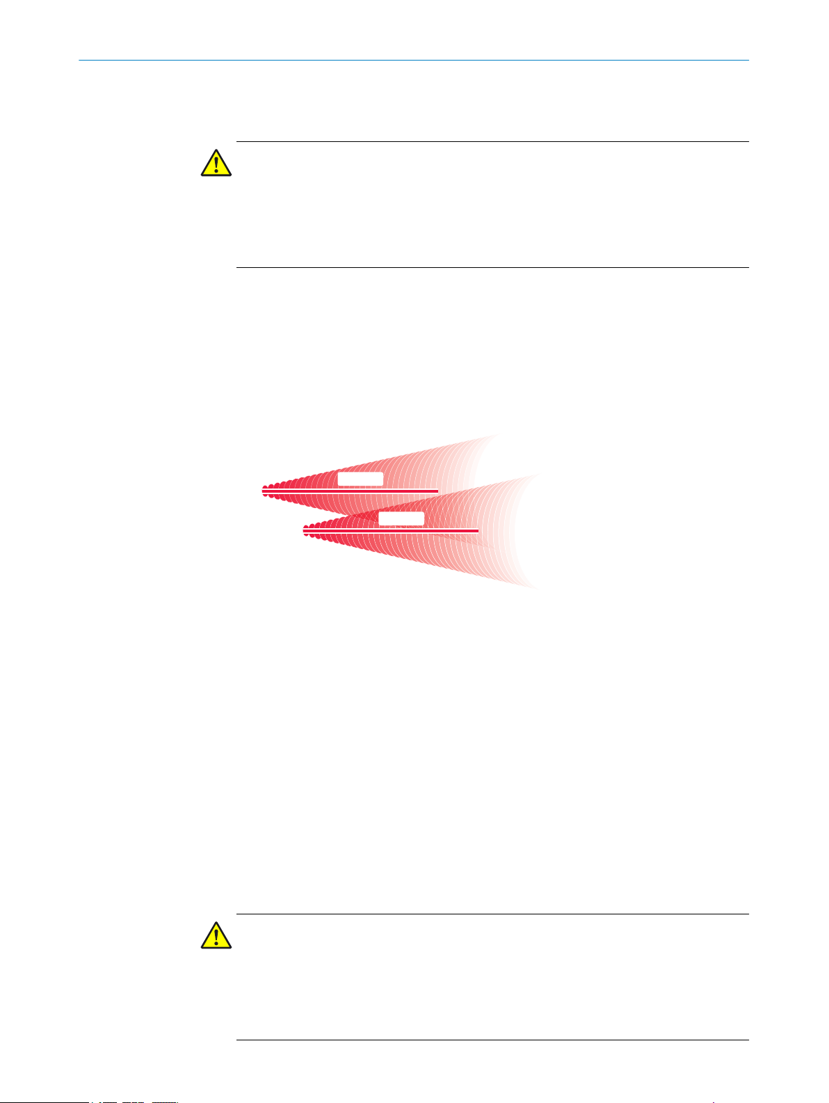
4.3.5.1 Using beam coding
s
Code 1
r
s
Code 2
r
Important information
DANGER
Hazard due to lack of effectiveness of the protective device
Different beam codings only prevent mutual interference if both safety light curtains are
of type miniTwin4.
b
Using beam coding
PROJECT PLANNING 4
In the case of systems in close proximity that are of a different type, take different
measures to prevent mutual interference.
Use suit
b
The system automatically performs the coding. As soon as a system is influenced by
another system with an identical code, a fault occurs. During the next power-up, the
code is converted and operation is no longer possible.
Figure 19: Trouble-free operation due to beam coding
In t
The system with code 2 is not affected by the beams of the system with code 1.
able beam codings to prevent mutual interference from neighboring systems.
Configure one safety light curtain with code 1 and the other safety light curtain
with code 2.
he figure, the beam coding of systems in close proximity to each other is different.
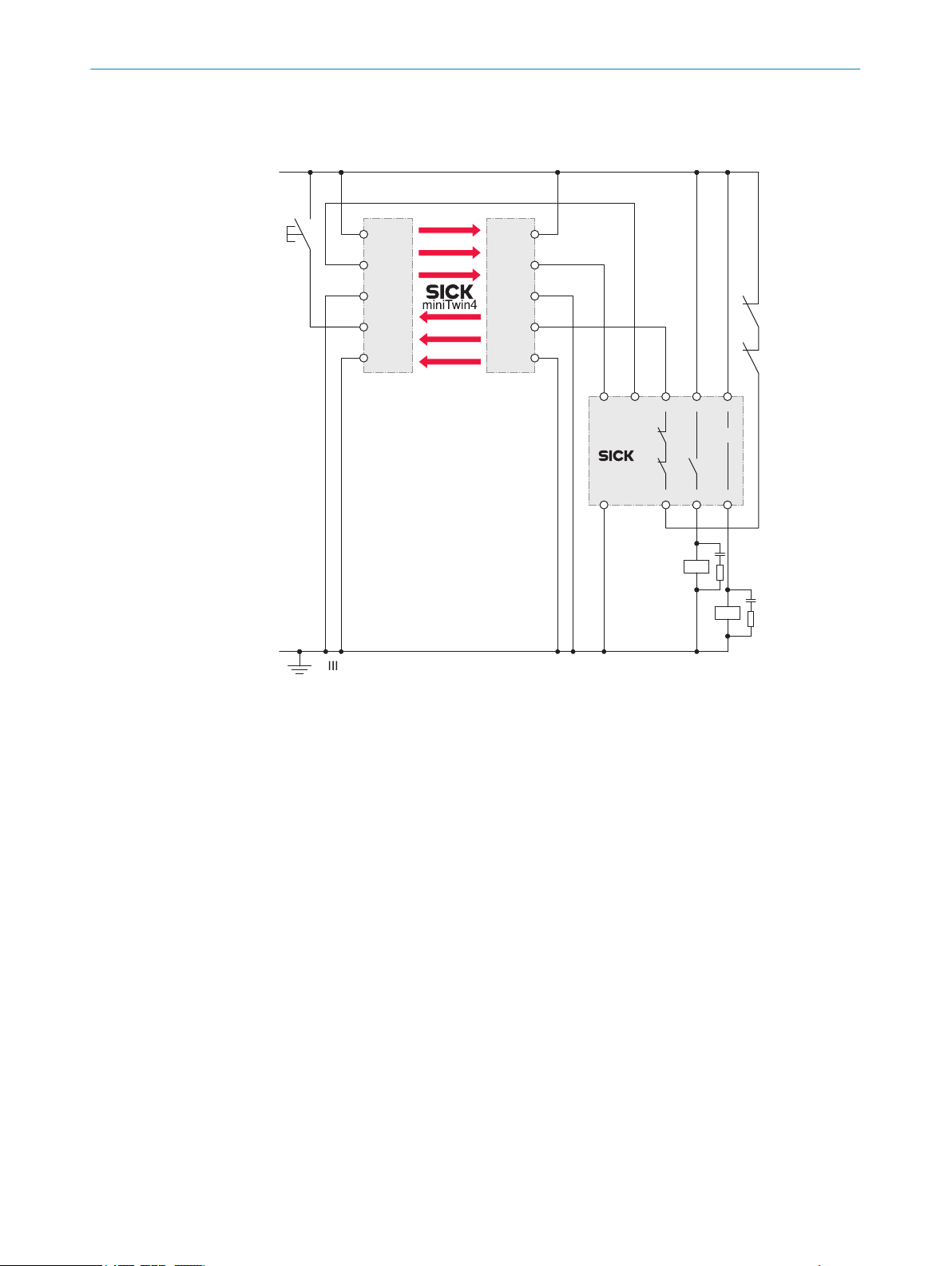
4.4 Integrating the equipment into the electrical control
Overview
T
his chapter contains important information about integration in the electrical control.
Information about the individual steps for electrical installation of the device: see "Elec‐
trical installation", page 60.
Requirements for use
The output signals of the protective device must be analyzed by downstream controllers
in such a way that the dangerous state of the machine is ended safely. Depending on
the safety concept, the signal is analyzed by safety relays or a safety controller, for
example.
DANGER
azard due to lack of effectiveness of the protective device
H
In the case of non-compliance, it is possible that the dangerous state of the machine
8012624/10OM/2018-08-09 | SICK O PE R AT I NG IN S TR U CT I ON S | miniTwin4
Subject to change without notice
may not be stopped or not stopped in a timely manner.
Make sure that the following control and electrical requirements are met so that
b
the safety light curtain can fulfill its protective function.
29
Page 30
OSSD1
OSSD2
OSSD1
OSSD2
O
S
SD
0 V
OSSD
0 V
4 PROJECT PLANNING
t be possible to electrically influence the control of the machine
It mus
•
The electrical control of the machine must meet the requirements of IEC 60204-1
•
When using a safety controller, different signal levels of both OSSDs must be
•
detected depending on applicable national regulations or required reliability of the
safety function. The maximum discrepancy time tolerated by the control must be
selected according to the application.
The OSSD1 and OSSD2 output signals must not be connected to each other
•
In the machine controller, the signals of both OSSDs must be processed sepa‐
•
rately
Figure 20: Dual-channel and isolated connection of OSSD1 and OSSD2
he machine must switch to the safe state at any time if at least one of the two
T
•
OSSDs switches to the OFF state
Prevent the formation of a potential difference between the load and the protec‐
•
tive device. If loads are connected to the OSSDs (switching outputs) that then also
switch if controlled with negative voltage (e.g., electro-mechanical contactor with‐
out reverse polarity protection diode), the 0 V connections of these loads and
those of the corresponding protective device must be connected individually and
directly to the same 0 V terminal strip. In the event of a fault, this is the only way to
ensure that there can be no potential difference between the 0 V connections of
the loads and those of the corresponding protective device.
30
Figure 21: No potential difference between load and protective device
DANGER
azard due to unexpected starting of the machine
H
A restart interlock must be implemented depending on applicable national regulations
or required reliability of the safety function.
Make sure that a restart interlock is implemented.
b
O PE R AT I NG IN S TR U CT I ON S | miniTwin4 8012624/10OM/2018-08-09 | SICK
Subject to change without notice
Page 31

PROJECT PLANNING 4
DANGER
azard due to lack of effectiveness of the protective device
H
In the case of non-compliance, it is possible that the dangerous state of the machine
may not be stopped or not stopped in a timely manner.
Downstream contactors must be positively guided and monitored depending on applic‐
able national regulations or required reliability of the safety function.
Make sure that downstream contactors are monitored (external device monitoring,
b
EDM).
Requirements for the electrical control of the machine
th outputs are short-circuit protected to 24 V DC and 0 V. When the protective field is
Bo
clear, the OSSDs are in the ON state. When a switch-off condition is present (e.g., inter‐
ruption in the light path), the OSSDs are in the OFF state. In the event of a device fault,
at least one OSSD is in the OFF state.
The safety light curtain complies with the rules for electromagnetic compatibility (EMC)
for the industrial sector (Radio Safety Class A).
Radio interference cannot be ruled out when used in residential areas.
NOTE
Usin
g the device in residential areas may cause radio interference. The operating entity
is responsible for taking appropriate measures (e.g., shielding).
DANGER
H
azard due to lack of effectiveness of the protective device
In the case of non-compliance, it is possible that the dangerous state of the machine
may not be stopped or not stopped in a timely manner.
Make sure that the following control and electrical requirements are met so that
b
the safety light curtain can fulfill its protective function.
T
he external voltage supply of the safety light curtain must be capable of jumper‐
•
ing a brief power failure of 20 ms as specified in IEC 60204-1.
The power supply unit must ensure safe isolation according to IEC 61140
•
(SELV/PELV). Suitable power supply units are available as accessories from SICK,
see "Accessories", page 101.
4.4.1 Protective operation without reset and/or without EDM
If the miniTwin4 safety light curtain is configured in protective operation without reset
and/or EDM, t
he respective multifunctional connection or both multifunctional connec‐
tions must be routed to 0 V.
8012624/10OM/2018-08-09 | SICK O PE R AT I NG IN S TR U CT I ON S | miniTwin4
Subject to change without notice
31
Page 32

Pi
n
2
Pi
n
4
Pi
n
4
Pi
n
2
K1
K2
0 V DC
0 V DC
4 P
ROJECT PLANNING
Figure 22: Connection of multifunctional connections in protective operation without reset
and/or w
ithout EDM
4.4.2 Restart interlock
Overview
T
he safety light curtain has an internal restart interlock.
Depending on the regulations which apply at the place of installation, a restart interlock
may be required.
The restart interlock prevents the machine from automatically starting up, for example
after a protective device has responded while the machine is operating or after chang‐
ing the machine’s operating mode.
Important information
DANGER
azard due to unexpected starting of the machine
H
The machine may not restart if the OSSDs switch to the ON state once the reset push‐
button has been pressed. The control must ensure that the machine only restarts if the
machine start button is also pressed after the reset pushbutton.
b
Operating principle
T
he restart interlock prevents the machine from automatically starting up, for example
after a protective device has responded while the machine is operating or after chang‐
ing the machine’s operating mode.
Make sure that the machine can only restart once the reset pushbutton and start
button have been pressed in the specified order.
Before the machine can be restarted, the operator must reset the restart interlock.
32
O PE R AT I NG IN S TR U CT I ON S | miniTwin4 8012624/10OM/2018-08-09 | SICK
Subject to change without notice
Page 33
!
§" $
Pi
n
4
Pi
n
2
+24 V DC
0 V DC
K1
K2
Pi
n
2
Pi
n
4
PROJECT PLANNING 4
Figure 23: Schematic representation of operation with restart interlock
he dangerous state of the machine (!) is brought to an end if the light path is inter‐
T
rupted (") and is not re-enabled (§) until the operator presses the reset pushbutton
located outside the hazardous area ($). The machine can then be restarted.
Depending on applicable national regulations, a restart interlock must be available if it
is possible to stand behind the protective field. Observe IEC 60204-1.
The following applies to the restart interlock:
If the protective field is clear once the machine has been switched on or following
•
an interruption, the OSSDs do not switch to the ON state
If someone presses the reset pushbutton and then lets go of it when the protec‐
•
tive field is clear, the OSSDs switch to the ON state
The machine may not restart yet. The operator must also press the machine start
•
button after having pressed the reset pushbutton.
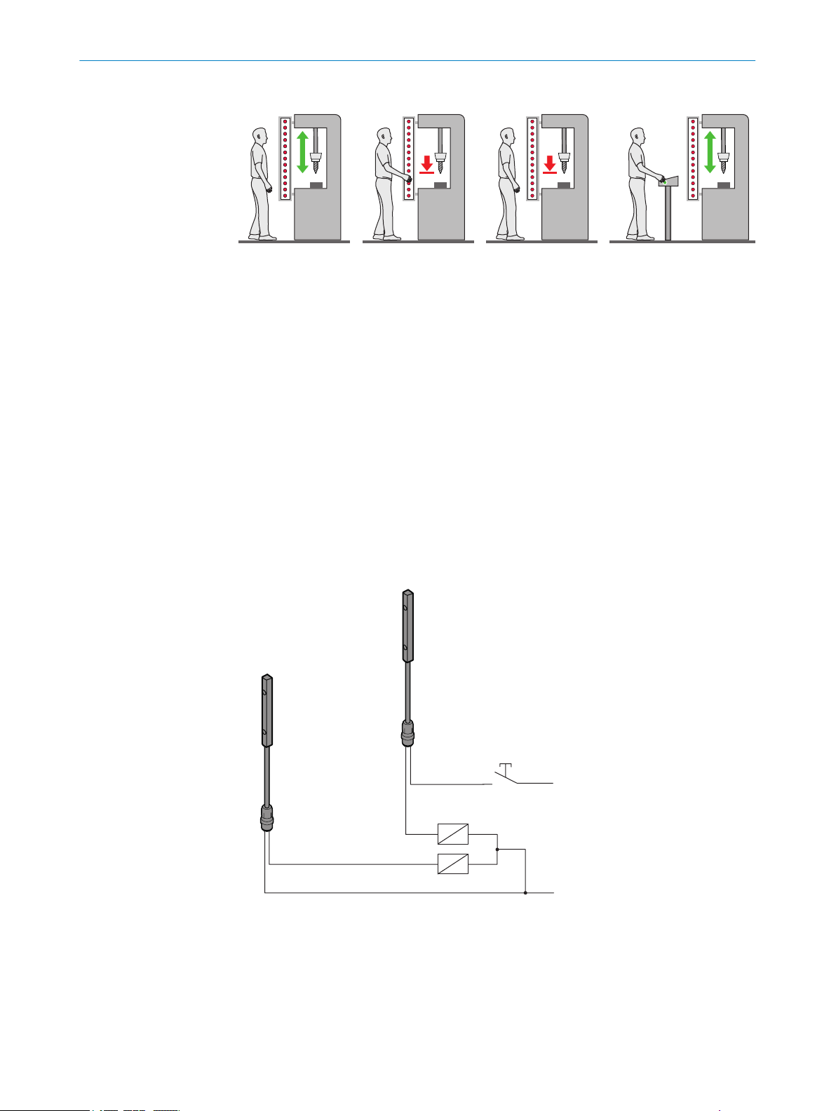
Internal restart interlock and reset
A r
eset device (e.g., a reset pushbutton) must be connected to allow the restart inter‐
lock to be used.
Figure 24: Electrical diagram of the reset device
he restart interlock is configured once the reset pushbutton has been connected.
T
Only one reset pushbutton may be connected to a single safety light curtain. A total of
just one reset pushbutton may be connected to a cascade comprising 2 or 3 safety
light curtains.
8012624/10OM/2018-08-09 | SICK O PE R AT I NG IN S TR U CT I ON S | miniTwin4
Subject to change without notice
33
Page 34
Pi
n
4
Pi
n
2
Pi
n
2
Pi
n
4
K1
k1
k2
K2
0 V DC
24 V DC
ROJECT PLANNING
4 P
For a single system, the reset pushbutton can be connected to the 5-pin system con‐
nec
tion.
In a cascade, the reset pushbutton can be connected to the 5-pin system connection of
the host twin stick.
When the restart interlock is configured, the RES LED signals when the reset pushbut‐
ton needs to be pressed.
Further topics
"C
onfiguring reset", page 64
•
4.4.3 External device monitoring (EDM)
Overview
T
he safety light curtain has internal external device monitoring.
The external switching elements (external device monitoring, EDM) must be inspected
in line with the regulations which apply at the place of installation or the required relia‐
bility of the safety function.
The external device monitoring (EDM) monitors the status of downstream contactors.
Prerequisites
Use posit
•
Connect the auxiliary contacts of the positively guided contactors to the external
•
ively guided contactors for shutting down the machine.
device monitoring (EDM).
Operating principle
If e
xternal device monitoring is configured, the safety light curtain then checks the con‐
tactors after every interruption to the light path and before the machine restarts. Exter‐
nal device monitoring is then able to detect if one of the contactor’s contacts is welded,
for instance. In this case, the OSSDs remain in the OFF state.
Figure 25: Electrical diagram of external device monitoring (EDM)
T
he external device monitoring must be implemented electrically so that the two N/Cs
(k1, k2) close in a positively guided manner when the contactors (K1, K2) reach their
de-energized position once the protective device has responded. 24 V are then present
at the input of external device monitoring. If 24 V are not present once the protective
device has responded, one of the contactors is defective and external device monitor‐
34
O PE R AT I NG IN S TR U CT I ON S | miniTwin4 8012624/10OM/2018-08-09 | SICK
ing prevents the machine from restarting.
Subject to change without notice
Page 35
4.4.4 Cascading
PROJECT PLANNING 4
Important information
DANGER
Risk of ineffectiveness of the protective device
The length of cable between 2 cascaded systems must not exceed 3 m.
Use the shortest possible cables between the devices of a cascaded system.
b
Protect the cascaded system from manipulation with an optimized length of cable
b
or with cable routing under a cover.
DANGER
azard due to lack of effectiveness of the protective device
H
Persons and parts of the body to be protected may not be recognized in case of nonobservance.
Maintenance work, alignment work, fault diagnoses, and any changes to the inte‐
b
gration of the protective device in the machine must only be carried out by quali‐
fied personnel.
The effectiveness of the protective device must be checked following such work.
b
NOTE
hen 2 or 3 safety light curtains are used in a cascade and the connecting cables are
W
later interchanged, if may be necessary to deactivate any guest configurations and
manually re-teach the restart interlock.
Integrating a safety light curtain in a cascade
C
ascading allows up to 3 safety light curtains to be connected, e.g. for reliable pres‐
ence detection. The connected devices act like a long safety light curtain. Only one
device, the host, is connected to the control cabinet. The second device, guest 1, is
connected to the host. The 3rd guest 2, is connected to guest 1.
Advantages of cascading:
Rapid connection, no additional external circuitry required
•
No optical mutual interference between the protective fields within a cascade.
•
Host and guests are operated automatically and without configuration with the
alternating beam coding.
Resolution and protective field heights of the individual systems may be different
•
8012624/10OM/2018-08-09 | SICK O PE R AT I NG IN S TR U CT I ON S | miniTwin4
Subject to change without notice
35
Page 36

!
"
§
4 P
ROJECT PLANNING
Figure 26: Cascading
Host
!
Guest 1
"
Guest 2
§
The following system plugs are available for cascading:
S
ystem plug for single systems with an M12×4 + FE system connection (male con‐
•
nector)
System plug for cascaded systems with an M12×4 + FE system connection (male
•
connector) and an M12×4 + FE extension connection (female connector)
A cascaded system with several safety light curtains is configured solely through the
selection of the system plug (single system or cascade) and its cabling. No other action
is necessary.
The individual safety light curtains can be used as single systems after disconnecting
them from the cascaded systems if they are connected via a system plug for single sys‐
tems.
36
O PE R AT I NG IN S TR U CT I ON S | miniTwin4 8012624/10OM/2018-08-09 | SICK
Subject to change without notice
Page 37

PROJECT PLANNING 4
Use of system plugs in a cascade
R
equirements: extension connection at the host. 5-pin system connection at the
•
guest devices.
Additional requirement for cascades with 2 guest devices: Extension connection at
•
the devices of the first guest system
Restart interlock and external device monitoring (EDM) can be configured in the
•
host
Table 4: Use of system plugs in a cascade
System plug with system
connection and extension
connection
✓
–
✓
✓
–
Cascade with one
guest
Cascade with two
st devices
gue
✓
System plug suitable.
–
System plug not suitable.
Device type System plug with system
onnection
c
Host –
Guest 1
Host –
Guest 1 –
Guest 2
✓
✓
Complementary information
If a de
vice which may already have been configured is used to extend a cascade or
replace a (defective) device in a cascade, see table 9, page 66.
Further topics
"Deactivating reset and EDM", Seite 66
•
8012624/10OM/2018-08-09 | SICK O PE R AT I NG IN S TR U CT I ON S | miniTwin4
Subject to change without notice
37
Page 38
+24 V
S1
0 V
K1
B1
B2
Y1
13
23
A2
UE10-2FG
Y2
14
24
K1
K2
K2
1
+24 V
OSSD
0 V
Mtfkp
FE
+24 V
OSSD
0 V
M
tfkp
FE
4
3
2
5
1
4
3
2
5
PELV
4 P
ROJECT PLANNING
4.4.5 Connection diagrams
UE10-2FG
Figure 27: miniTwin4 in connection with UE10-2FG
38
O PE R AT I NG IN S TR U CT I ON S | miniTwin4 8012624/10OM/2018-08-09 | SICK
Subject to change without notice
Page 39

UE10-3OS
+24 V
S1
0 V
PELV
1
+24 V
OSSD
0 V
Mtfkp
FE
+24 V
OSSD
0 V
M
tfk
p
FE
K1
K1
K2
B1
UE10-3 OS
B3
Y1
13
23
33
41
B2
B4
Y2
14
24
34
42
K2
4
3
2
5
1
4
3
2
5
+24 V
S1
0 V
K1
K1
K2
l
1
l
2
A1
X1
X2
S1
S2
S3
l
3
l
4
A2
Q1
Q2
Q3
Q4
F
unct
ion
EN
FE
K2
PELV
1
+24 V
OSSD
0 V
Mtfkp
FE
+24 V
OSSD
0 V
Mtfkp
FE
4
3
2
5
1
4
3
2
5
PROJECT PLANNING 4
Figure 28: miniTwin4 in connection with UE10-3OS
Flexi Classic
Figure 29: miniTwin4 with Flexi Classic safety controller
8012624/10OM/2018-08-09 | SICK O PE R AT I NG IN S TR U CT I ON S | miniTwin4
Subject to change without notice
39
Page 40
+24 V
0
V
PELV
1
+24 V
OSSD
0 V
Mtfkp
FE
+24 V
OSSD
0 V
Mtfkp
FE
4
3
2
5
1
4
3
2
5
K1
K1
S1
K2
K2
A1
I1
I
2
I3
I
4
I5
I6
X1
FE
FE
A2
A1
A2
I7
I
8
Q1
Q2
Q3
Q4
X2
Fl
e
xi
Soft XTIO
FLEXI
s
oft
CPU
4 P
ROJECT PLANNING
Flexi Soft
Figure 30: miniTwin4 with Flexi Soft safety controller
4.5 Testing plan
The manufacturer of the machine and the operator must define all required checks.
T
he definition must be based on the application conditions and the risk assessment
and must be documented in a traceable manner.
When defining the check, please note the following:
b
Define the type and execution of the check.
°
Define the frequency of the check.
°
Notify the machine operators of the check and instruct them accordingly.
°
The following checks are often defined in connection with a protective device:
Check during commissioning and modifications
•
Regular thorough check
•
Check during commissioning and modifications
The check must detect if it is possible to enter the hazardous area without being
detected.
The following points are often helpful for the definition of the check:
Does the check have to be completed by qualified safety personnel?
•
Can the check be completed by personnel specially qualified and authorized to do
•
so?
Does the check have to be documented in a traceable manner?
•
Can the check be carried out according to a check list?
•
Do the machine operators know the function of the protective device?
•
Have the machine operators been trained to work on the machine?
•
Have the machine operators been notified about modifications to the machine?
•
Does the hazardous area being secured have to be checked with a test rod?
•
Define all guidelines for the check.
b
40
O PE R AT I NG IN S TR U CT I ON S | miniTwin4 8012624/10OM/2018-08-09 | SICK
Subject to change without notice
Page 41

4.5.1 Test rod check
PROJECT PLANNING 4
Regular thorough check
T
he check must detect if it is possible to enter the hazardous area without being
detected. Such possibilities may exist due to modifications, manipulations or external
influences.
The following points are often helpful for the definition of the check:
Which check must be carried out and how is it carried out?
•
Test rod check
°
Visual check of the machine and the protective device
°
How often does the check have to be carried out?
•
Do the machine operators have to be notified of the check and do they need to be
•
instructed accordingly?
Define all guidelines for the check.
b
Further topics
"Chec
•
•
•
klist for initial commissioning and commissioning", page 107
"Test rod check", page 41
"Visual check of the machine and the protective device", page 43
Overview
T
he rod test check is used to check whether the hazardous point is only accessible via
the protective field of the safety light curtain and whether the protective device is able
to identify each time the hazardous point is approached.
The test is carried out with an opaque test rod whose diameter corresponds to the reso‐
lution of the safety light curtain.
If several safety light curtains are connected to each other in a cascade, the complete
check for every safety light curtain in the cascade is carried out. During the check,
watch the OUT LED and the RES LED of the twin stick that is being checked.
Important information
DANGER
Use of incor
Persons or parts of the body to be protected may not be detected in operation.
b
b
DANGER
H
azard due to unexpected starting of the machine
rect test rods
Only use the included test rod with the diameter specified on the type label of the
safety light curtain.
Do not use any test rods with a similar or the same diameter of other safety light
curtains.
Make sure that the dangerous state of the machine is and remains switched off
b
during the check.
Make sure that the outputs of the safety light curtain have no effect on the
b
machine during the check of the components.
8012624/10OM/2018-08-09 | SICK O PE R AT I NG IN S TR U CT I ON S | miniTwin4
Subject to change without notice
41
Page 42

ROJECT PLANNING
4 P
DANGER
azard due to lack of effectiveness of the protective device
H
Persons and parts of the body to be protected may not be recognized in case of nonobservance.
Do not operate the machine if the OUT LED lights up green or the RES LED flashes
orange during the check!
If the OUT LED lights up green or the RES LED flashes orange during the test, even
b
if only briefly, work must stop at the machine.
In this case, the mounting and configuration of the safety light curtain must be
b
checked by qualified safety personnel (siehe "Mounting", Seite 44).
Before inserting the test rod, check whether the OUT LED lights up green if the
b
reset function is deactivated or the RES LED flashes orange if the reset function is
configured (“reset required”). If this is not the case, this status must first be
induced. The check is otherwise meaningless.
Approach
Move the test rod slowly through the area to be protected (e.g., machine opening),
1.
as indicated by the arrow, see figure 31.
2. Watch the OUT LED and the RES LED during the check. The OUT LED should con‐
tinuously light up red. The RES LED must not flash orange.
42
Figure 31: Test rod check: Step 1
3. Then, guide the test rod along the edges of the area to be protected, as indicated
b
y the arrow, see figure 32.
4. Watch the OUT LED and the RES LED during the check. The OUT LED should con‐
tinuously light up red. The RES LED must not flash orange.
O PE R AT I NG IN S TR U CT I ON S | miniTwin4 8012624/10OM/2018-08-09 | SICK
Subject to change without notice
Page 43

PROJECT PLANNING 4
Figure 32: Test rod check: Step 3
5. If one or more deflector mirrors are used, then the test rod should also be guided
slo
wly through the area to be protected directly in front of the deflector mirrors.
6. Watch the OUT LED and the RES LED during the check. The OUT LED should con‐
tinuously light up red. The RES LED must not flash orange.
7. After the test rod has been removed from the protective field, make sure that the
protective field is clear. If the reset function is deactivated, the OUT LED lights up
green again. If the reset function is configured, the RES LED flashes orange again.
8. If several safety light curtains are connected to each other in a cascade, carry out
the complete check for every safety light curtain in the cascade. During the check,
watch the OUT LED and the RES LED of the twin stick that is being checked.
4.5.2 Visual check of the machine and the protective device
The following points are often helpful for the definition of the check:
H
as the machine been retrofitted?
•
Have machine parts been removed?
•
Have modifications been made to the surroundings of the machine?
•
Have the protective device or its parts been dismantled?
•
Is it possible to enter the hazardous area without being detected?
•
Is the protective device damaged?
•
Is the protective device severely contaminated?
•
Is the front screen contaminated, scratched or destroyed?
•
Are there any damaged cables or open cable ends?
•
If one of the points applies, the machine should be shut down immediately. In this case,
the machine and the protective device must be checked by appropriately qualified
safety personnel.
8012624/10OM/2018-08-09 | SICK O PE R AT I NG IN S TR U CT I ON S | miniTwin4
Subject to change without notice
43
Page 44

5 MOUN
TING
5 Mounting
5.1 Safety
Important information
DANGER
D
angerous state of the machine
Make sure that the dangerous state of the machine is (and remains) switched off
b
during mounting, electrical installation, and commissioning.
Make sure that the outputs of the safety light curtain do not affect the machine
b
during mounting, electrical installation, and commissioning.
DANGER
azard due to lack of effectiveness of the protective device
H
If unsuitable brackets are used or if subjected to excessive vibrations, the device may
become detached or damaged.
Persons and parts of the body to be protected may not be recognized in case of nonobservance.
Only use SICK-approved brackets for mounting.
b
Take appropriate measures for vibration damping if vibration and shock specifica‐
b
tions exceed the values and test conditions specified in the data sheet.
DANGER
azard due to lack of effectiveness of the protective device
H
Persons and parts of the body to be protected may not be recognized in case of nonobservance.
Do not do repair work on device components.
b
Do not make changes to or manipulate device components.
b
Apart from the procedures described in this document, the device components
b
must not be opened.
NOTE
Mount t
Prerequisites
•
Further topics
•
•
he device in the following order.
T
he safety light curtain has been designed correctly.
"Design", page 21
"Technical data", page 89
5.2 Unpacking
44
O PE R AT I NG IN S TR U CT I ON S | miniTwin4 8012624/10OM/2018-08-09 | SICK
Approach
1.
Check the components for completeness and the integrity of all parts.
2. Please contact your SICK subsidiary should you have any complaints.
Further topics
"Scope of delivery", page 95
•
Subject to change without notice
Page 45

5.3 Mounting the system plug
!
"
§
!
$
"
§
Overview
he safety light curtain is already connected to the device connection using a system
T
plug:
For single systems: system plug with system connection
•
For cascaded systems: system plug with system connection and extension connec‐
•
tion.
MOUNTING 5
Figure 33: System plug with system connection
System plug
!
System connection
"
Device connection
§
Figure 34: System plug with system connection and extension connection
Extension connection
!
System plug
"
System connection
§
Device connection
$
8012624/10OM/2018-08-09 | SICK O PE R AT I NG IN S TR U CT I ON S | miniTwin4
Subject to change without notice
45
Page 46

5 MOUN
TING
Important information
DANGER
azard due to lack of effectiveness of the protective device
H
Malfunctions can occur if the safety light curtain is connected other than with one of
the system plugs provided.
Use the system plugs provided.
b
Approach
1.
Connect the system plug to the device connection when powered down.
2. Fasten the screws of the system plugs using a maximum torque of 1 Nm.
3. In a cascade: First connect the single systems to one another. To do so, connect
the extension connections of the host devices to the system connections of guest
device 1 and, if applicable, the extension connections of guest device 1 to the sys‐
tem connections of guest device 2.
4. Then connect the system connections of the single system or host system to the
application connection.
Complementary information
The system plug can also be mounted to the device connection at an 180° rotation.
46
O PE R AT I NG IN S TR U CT I ON S | miniTwin4 8012624/10OM/2018-08-09 | SICK
Subject to change without notice
Page 47

!
"
§
$
MOUNTING 5
5.4 Mounting
Figure 35: Mount the system plug, rotated by 180°, on the device connection
System plug for single systems
!
System plug for cascaded systems
"
System plug for cascaded systems, rotated by 180°
§
System plug for single systems, rotated by 180°
$
The individual safety light curtains can be used as single systems after disconnecting
t
hem from the cascaded systems if they are connected via a system plug for single sys‐
tems.
If a device which may already have been configured is used to extend a cascade or
replace a (defective) device in a cascade, see table 9, page 66.
Further topics
"D
eactivating reset and EDM", page 66
•
Important information
NOTE
ead this section completely before installing the safety light curtain.
R
b
Read the information on aligning the twin sticks.
b
8012624/10OM/2018-08-09 | SICK O PE R AT I NG IN S TR U CT I ON S | miniTwin4
Subject to change without notice
47
Page 48

5 MOUNTING
DANGER
azard due to lack of effectiveness of the protective device
H
Persons or parts of the body to be protected may not be recognized or not recognized in
time in case of non-observance.
Observe the calculated minimum distances for the machine in which the safety
b
light curtain is integrated.
Then, mount the safety light curtain such that it is not possible to reach over,
b
under or around, or to stand behind the safety light curtain, and that the light cur‐
tain cannot be repositioned.
DANGER
azard due to lack of effectiveness of the protective device
H
Persons and parts of the body to be protected may not be recognized in case of nonobservance.
The safety light curtain can only be mounted on machines on which the protective
b
field width does not change when the safety light curtain is switched on.
CAUTION
T
o consider during mounting:
Mount the twin sticks on a level surface.
b
When mounting, make sure that the safety light curtain is aligned correctly. The
b
two housings of the twin sticks must be located exactly opposite one another.
Take appropriate measures for vibration damping if shock specifications exceed
b
the values in the data sheet section.
When mounting, observe the minimum distance of the system.
b
Then, mount the safety light curtain such that it is not possible to reach over,
b
under or to stand behind the safety light curtain, and that the light curtain cannot
be repositioned.
48
Figure 36: With correct mounting (above), the standing behind, reaching under and reach‐
in
g over errors (below) must be ruled out.
O PE R AT I NG IN S TR U CT I ON S | miniTwin4 8012624/10OM/2018-08-09 | SICK
Subject to change without notice
Page 49

Further topics
s
s
r
r
! !
MOUNTING 5
"Minimum dis
•
"Minimum distance from reflective surfaces", page 25
•
"Data sheet", page 89
•
"Design", page 21
•
5.4.1 Mounting direction of the twin stick
Overview
T
he safety light curtain consists of 2 identical twin sticks. Each twin stick contains both
the sender as well as the receiver unit, (figure X). Install the twin sticks so that the opti‐
cal elements are located opposite one another. To do so, rotate one twin stick by 180°
so that the sender unit of twin stick 1 points towards the receiver unit of twin stick 2. If
the EDM LED of twin stick 1 points towards LED 5 of twin stick 2, they have been
installed correctly.
tance from the hazardous point", page 23
Figure 37: Mounting direction of the twin stick
Twin stick
!
NOTE
After electrical installation, the quality of the alignment of the safety light curtain can
be checked. During mounting, make sure the twin sticks are aligned to one another.
Further topics
gnment of the twin stick", page 74
"Ali
•
5.4.2 Mounting options
Possible ways of mounting theminiTwin4:
T
able 5: Mounting options
Bracket Protective field
O-Fix ≥ 180 mm
C-Fix ≥ 180 mm
8012624/10OM/2018-08-09 | SICK O PE R AT I NG IN S TR U CT I ON S | miniTwin4
Subject to change without notice
hei
ght
Application features Page
ixed mounting position
F
•
Flush-mounted
•
Not suitable for cascading.
•
Flexible mounting position page 52
•
page 50
49
Page 50
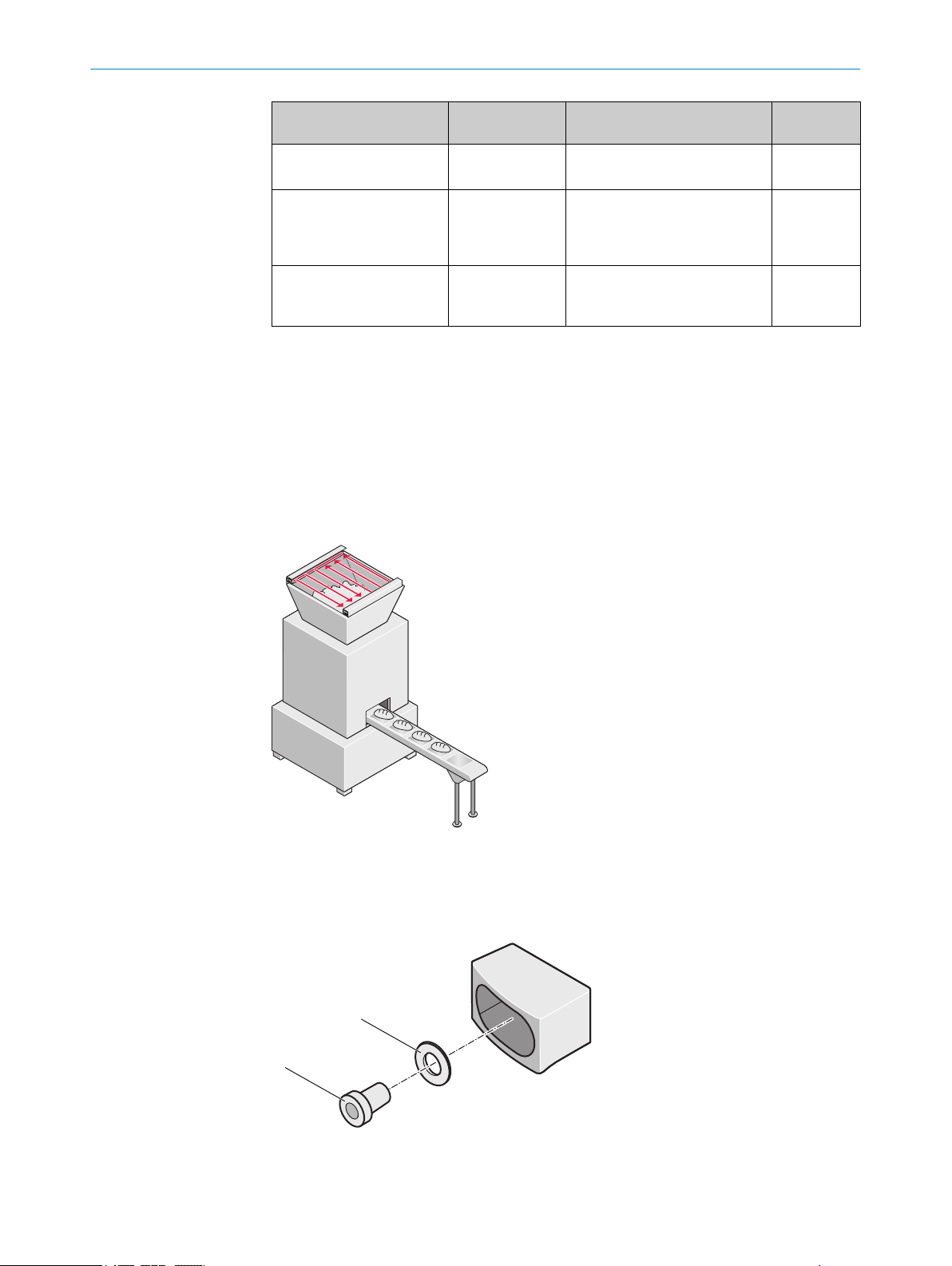
!
"
5 MOUNTING
Bracket Protective field
L-Fix ≤ 540 mm
Combination of C-Fix/L-Fix ≥ 240 mm
C-Fix-Flex ≥ 180 mm
More information can be found at www.sick.com.
Further topics
ackets", page 101
"Br
•
5.4.3 Mounting with O-Fix bracket
Overview
W
ith the O-Fix bracket, the safety light curtain can be mounted flat, e.g. directly on the
machine bed.
hei
ght
Application features Page
ixed mounting position
F
•
Not suitable for cascading.
•
Fixed mounting position of
•
L-Fix bracket
Flexible mounting position
•
of C-Fix bracket
lexible mounting position
F
•
Flexible alignment of the
•
protective field
page 53
page 55
page 56
50
Figure 38: Application example, mounting with O-Fix bracket
he O-Fix bracket is mounted at the top and bottom of the miniTwin4 safety light cur‐
T
tain. Due to the O-Fix bracket, the respective twin stick is extended on both sides by
about 13 mm (see figure 66, page 101).
Figure 39: O-Fix bracket, part no. 2045835
DIN 125 washer
!
O PE R AT I NG IN S TR U CT I ON S | miniTwin4 8012624/10OM/2018-08-09 | SICK
Subject to change without notice
Page 51
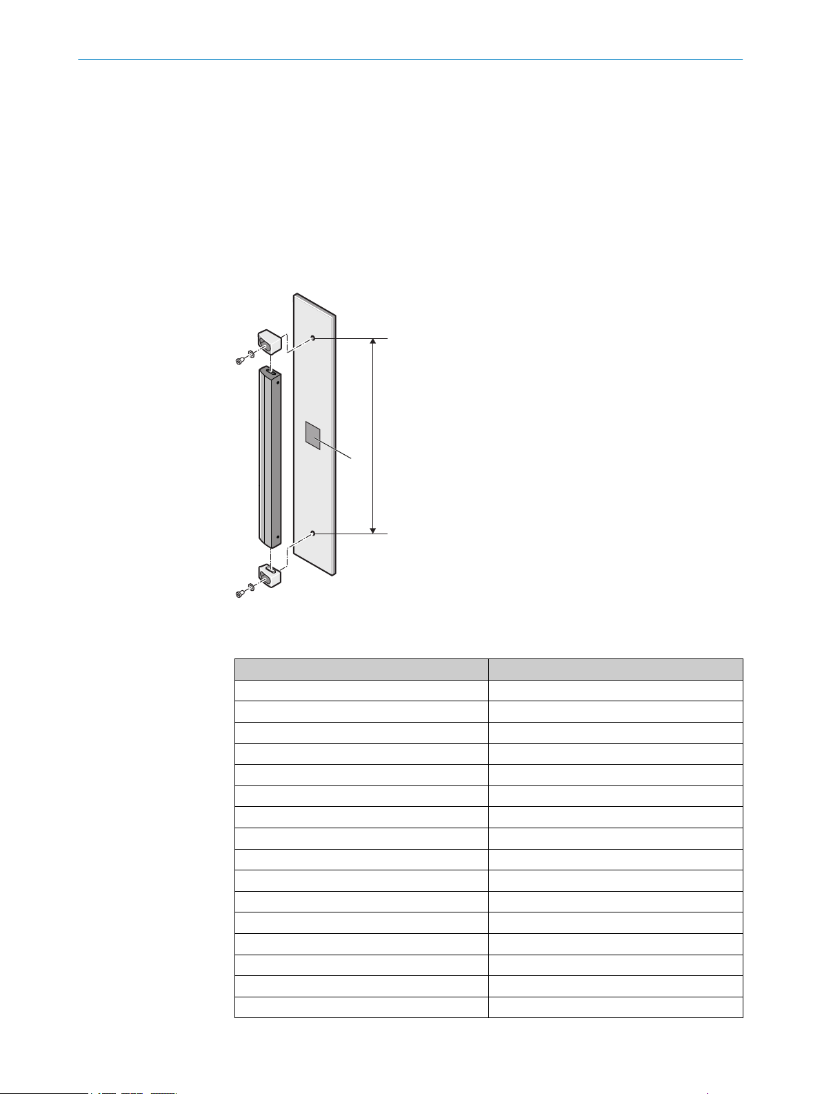
!
L
MOUNTING 5
M5 fixing screw
"
Approach
First mount the two O-Fix brackets at the correct positions, but do not yet tighten
1.
the fixing screws.
2. Insert the twin stick between the two O-Fix brackets. For applications in which
strong vibrations could occur, from a device length of 600 mm, stick the twin stick
to the mounting surface with two-sided tape (see !in figure 40).
3. Then fasten the screws of the O-Fix bracket with a torque of 5 Nm. Higher torques
can damage the brackets; lower torques provide inadequate protection against
displacement.
Figure 40: Mounting the miniTwin4with O-Fix bracket
T
able 6: Drilling distance for mounting with O-Fix bracket
Protective field height of the twin stick in mm Drilling distance L in mm
120 132.6
180 192.6
240 252.6
300 312.6
360 372.6
420 432.6
480 492.6
540 552.6
600 612.6
660 672.6
720 732.6
780 792.6
840 852.6
900 912.6
960 972.6
1020 1,032.6
8012624/10OM/2018-08-09 | SICK O PE R AT I NG IN S TR U CT I ON S | miniTwin4
Subject to change without notice
51
Page 52
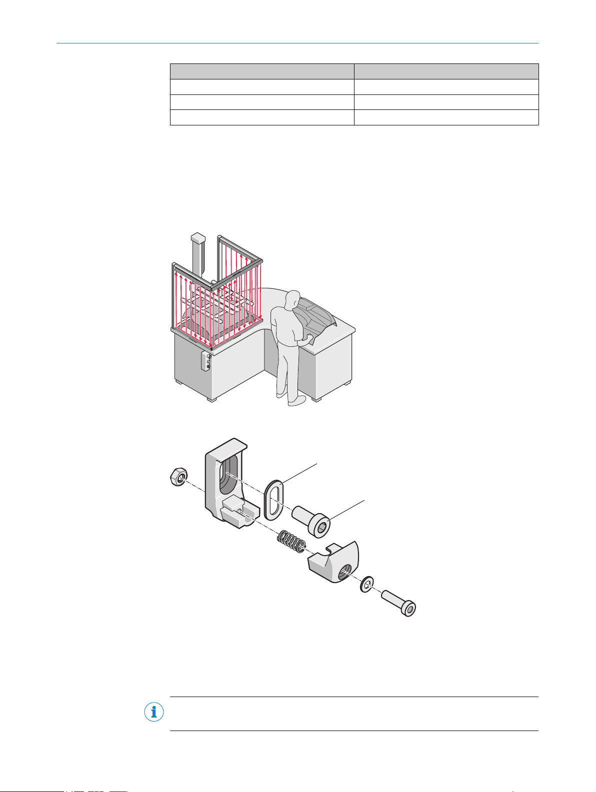
!
"
5 MOUNTING
Protective field height of the twin stick in mm Drilling distance L in mm
1080 1,092.6
1140 1,152.6
1200 1,212.6
5.4.4 Mounting with C-Fix bracket
Overview
T
he C-Fix bracket can be positioned very flexibly on the twin stick. It does not extend
the dimensions of the miniTwin4 safety light curtain.
With the C-Fix bracket, twin sticks can be mounted so they make contact or at right
angles to each other without harming the resolution at the junction points.
Figure 41: Application example, mounting with C-Fix bracket
Figure 42: C-Fix bracket, part no. 2045843
Washer
!
M5 fixing screw
"
Important information
NOTE
The C-Fix bracket cannot be used on a device with 120 mm protective field height.
52
O PE R AT I NG IN S TR U CT I ON S | miniTwin4 8012624/10OM/2018-08-09 | SICK
Subject to change without notice
Page 53

!
!
½ L
¼ L
¼
L
"
$
$
"
"
§
MOUNTING 5
Approach
1.
Mount t
height.
For applications in which vibrations could occur as well as for protective field
hei
a fourth of the twin stick length from the end of the twin stick.
2. Tighten the M5 screws with a torque of about 3 Nm. Higher torques can damage
the brackets; lower torques provide inadequate protection against displacement.
he C-Fix brackets (!) so that the twin stick is positioned at the correct
ghts of ≥ 360 mm, we recommend assembling the brackets at a distance from
Figure 43: Mounting the miniTwin4 with C-Fix brackets
3.
Inser
4.
Turn the twin stick to the rear until it engages in the C-Fix brackets (§).
5. Push the twin stick into the desired position.
6. To secure the twin stick ( ), tighten the M3 screws of the C-Fix brackets with a
torque of approx. 1.5$Nm.
5.4.5 Mounting with L-Fix bracket
Overview
T
he miniTwin4with a protective field height of 120 mm is mounted with the help of 2 LFix brackets.
t the twin stick into the C-Fix brackets and press downward gently (").
8012624/10OM/2018-08-09 | SICK O PE R AT I NG IN S TR U CT I ON S | miniTwin4
Subject to change without notice
53
Page 54
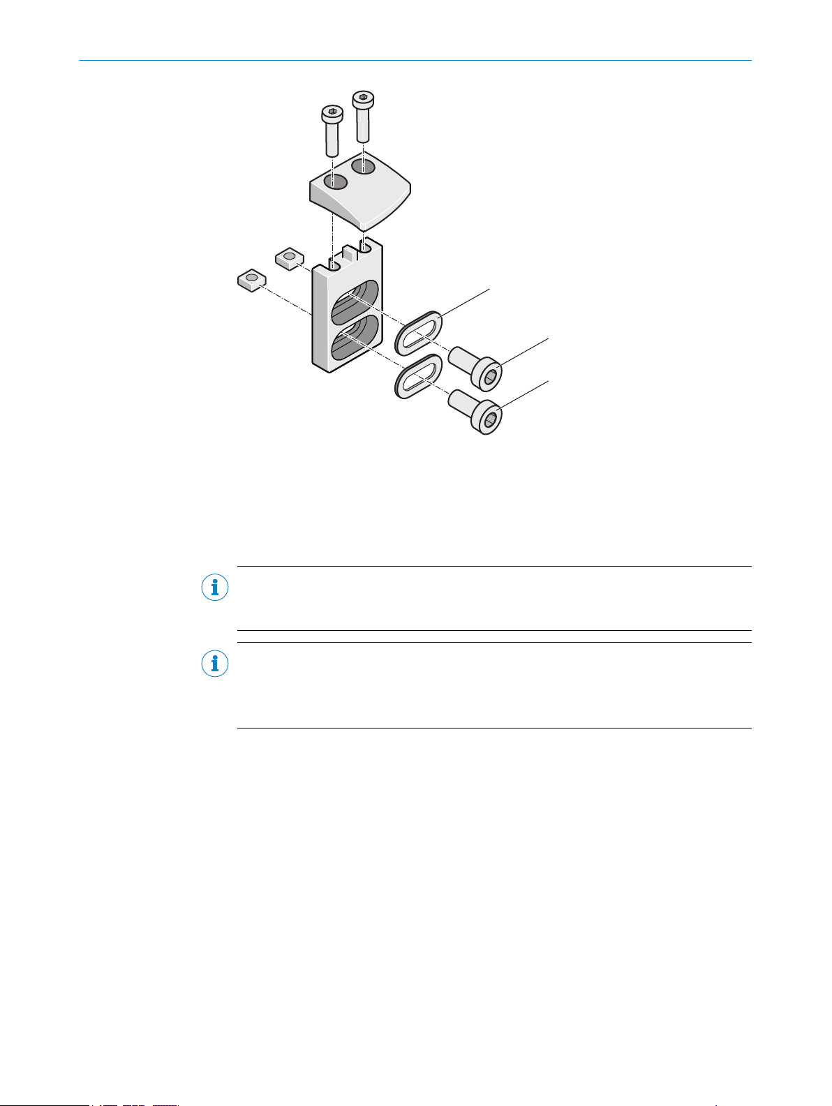
!
"
§
5 MOUN
TING
Figure 44: L-Fix bracket, part no. 2045843
Washers
!
1. M5 fixing screw
"
2. M5 fixing screw (optional)
§
Important information
NOTE
Mount
ing with 2 L-Fix brackets is only permitted up to a protective field height of
540 mm.
NOTE
T
ighten the screws of the L-Fix bracket with a torque of about 3 Nm. Higher
b
torques can damage the bracket; lower torques provide inadequate protection
against vibrations.
Approach
1.
Mount t
he L-Fix bracket (!) with assembled mounting limb (") on the mounting
surface so that the twin stick is positioned at the correct height.
2.
Mount the mounting plate (§) of the upper L-Fix bracket so that the upper twin
stick protrudes up to 1 mm.
3. At a protective field height of 420 mm, use 2 fixing screws per mounting plate to
increase protection against the L-Fix bracket twisting.
4.
Set the mounting limb ($) of the L-Fix bracket on the upper end cap of the twin
stick.
5.
Fasten the screws of the L-Fix bracket (%) with a torque of about 1.5 Nm to
achieve a corresponding clamping force of the bracket.
54
O PE R AT I NG IN S TR U CT I ON S | miniTwin4 8012624/10OM/2018-08-09 | SICK
Subject to change without notice
Page 55

!
§
%
"
$
Figure 45: Mounting the miniTwin4 with L-Fix bracket
5.4.6 Mounting with C-Fix bracket and L-Fix bracket
MOUNTING 5
Overview
T
he C-Fix bracket can be combined with the L-Fix bracket. This both fastens the position
of the safety light curtain and ensures flexible mounting of a C-Fix bracket.
For applications in which vibrations could occur as well as for protective field heights of
≥ 360 mm, we recommend assembling the brackets at a distance from a fourth of the
twin stick length from the end of the twin stick.
Figure 46: Application example, mounting with C-Fix bracket and L-Fix bracket
Approach
Mount the L-Fix bracket so that the twin stick is positioned at the correct height.
1.
2.
Tighten the first of the two M5 fixing screws (!) slightly.
Make sure that the L-Fix bracket is originally only lightly fastened and does not
r
otate.
3.
Now tighten the second of the two M5 fixing screws (") slightly.
4. Now tighten both M5 screws with a torque of about 3 Nm. Higher torques can
8012624/10OM/2018-08-09 | SICK O PE R AT I NG IN S TR U CT I ON S | miniTwin4
Subject to change without notice
damage the bracket; lower torques provide inadequate protection against vibra‐
tions.
55
Page 56
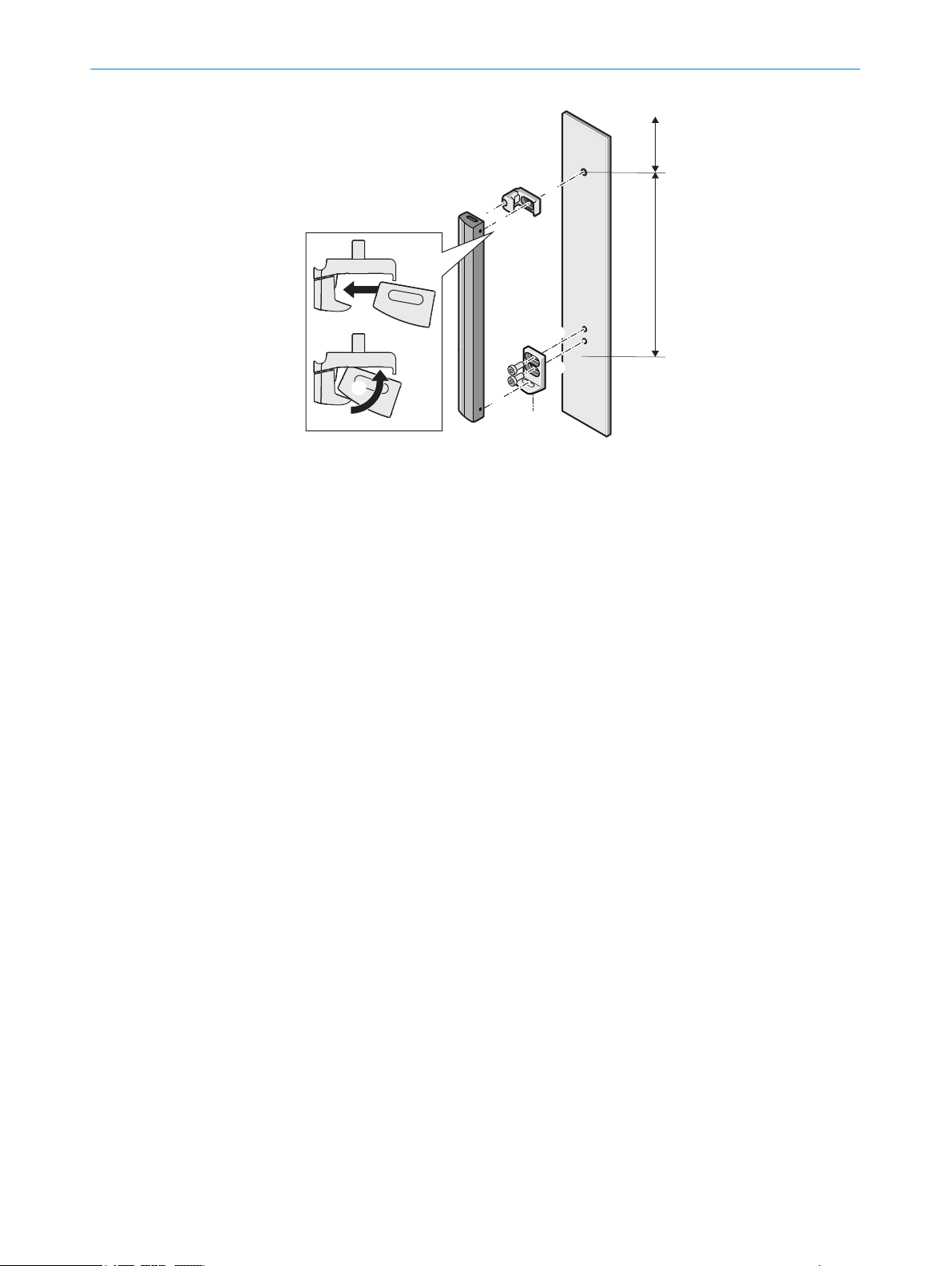
"
!
/
§
$
$
%
&
(
¼ L
¾ L
5 MOUN
TING
Figure 47: Mounting the miniTwin4 with C-Fix bracket and L-Fix bracket
5.
Mount t
For devices with a protective field height of ≥ 360 mm, w
an additional C-Fix bracket in the direct vicinity of the L-Fix bracket if there are
strong cross forces on the housing.
6.
Inser
7.
Turn the twin stick to the rear until it engages in the C-Fix bracket (%).
8. Turn the twin stick downwards until it is correctly positioned in the L-Fix bracket
(&).
9.
Tighten the M3 screws of the L-Fix bracket (/) with a torque of about 1.5 Nm.
10. To secure the twin stick ( ), tighten the M3 screws of the C-Fix bracket with a
torque of approx. 1.5(Nm.
he C-Fix bracket (§) at the other end of the twin stick.
e recommend also using
t the twin stick into the C-Fix bracket and press it downward gently ($).
5.4.7 Mounting with C-Fix-Flex bracket
Overview
T
he C-Fix-Flex bracket can be positioned very flexibly on the twin stick. It does not
extend the dimensions of the miniTwin4 safety light curtain.
With the C-Fix-Flex bracket, twin sticks can be mounted until they make contact or at
right angles to each other without harming the resolution at the junction points.
With the C-Fix-Flex bracket, twin sticks can be mounted so that the protective field is
either parallel or perpendicular to the mounting surface. The C-Fix-Flex bracket makes it
possible to correct the mounting bracket by ± 4°.
56
O PE R AT I NG IN S TR U CT I ON S | miniTwin4 8012624/10OM/2018-08-09 | SICK
Subject to change without notice
Page 57

!
Figure 48: C-Fix-Flex bracket, part no. 2056598
M5×16 fixing screw
!
MOUNTING 5
Important information
NOTE
T
he C-Fix-Flex bracket cannot be used on a device with 120 mm protective field height.
Approach
1.
Mount t
he C-Fix-Flex brackets (!) hand-tight at first so that the twin stick is posi‐
tioned at the correct height.
For applications in which vibrations could occur as well as for protective field
hei
ghts of ≥ 360 mm, we recommend assembling the brackets at a distance from
a fourth of the twin stick length from the end of the twin stick.
2. Insert the twin stick into the C-Fix-Flex brackets and press to the rear until it
engages (").
3. Push the twin stick into the desired position.
4. To secure the twin stick ( ), tighten the M3 screws of both C-Fix-Flex brackets with
a torque of approx. 1.5§Nm.
5.
Correct the bracket angle until alignment is optimal ($).
6. Tighten the M5 fixing screws of both C-Fix-Flex brackets with a torque of about
5 Nm. Higher torques can damage the bracket; lower torques provide inadequate
protection against vibrations (%).
8012624/10OM/2018-08-09 | SICK O PE R AT I NG IN S TR U CT I ON S | miniTwin4
Subject to change without notice
57
Page 58

§
%
!
!
"
"
$
4°
20,6
4°
3 mm
3 mm
4
° 4°
min. 29
min.
40
20,4
%
!
$
§
"
5 MOUN
TING
Figure 49: Mounting with C-Fix-Flex bracket, protective field parallel to the mounting surface
Figure 50: Mounting with C-Fix-Flex bracket, protective field perpendicular to mounting surface
5.5 Resolution at the end of the twin sticks
The resolution between 2 twin sticks (higher value)
The resolution for a junction point of a twin stick with a wall or the ground (lower
value)
Overview
veral safety light curtains are mounted so that they make contact or a safety light
If se
curtain is mounted on a wall, depending on the type of bracket, the resolution at the
junction points or ends of the twin sticks differs. figure 51 shows:
•
•
58
O PE R AT I NG IN S TR U CT I ON S | miniTwin4 8012624/10OM/2018-08-09 | SICK
Subject to change without notice
Page 59

7
14
20
40
13
2
6
!
"
§
MOUNTING 5
Figure 51: Resolution between twin sticks mounted so they have contact or a twin stick mounted
gainst a wall (mm) Example: Twin-Stick with 14 mm resolution
a
C-Fix bracket/C-Fix-Flex bracket
!
O-Fix bracket
"
L-Fix bracket
§
8012624/10OM/2018-08-09 | SICK O PE R AT I NG IN S TR U CT I ON S | miniTwin4
Subject to change without notice
59
Page 60

6 ELE
CTRICAL INSTALLATION
6 Electrical installation
6.1 Safety
Important information
DANGER
H
azard due to electrical voltage
Hazard due to unexpected starting of the machine
Make sure that the machine is (and remains) disconnected from the voltage sup‐
b
ply during the electrical installation.
Make sure that the dangerous state of the machine is (and remains) switched off
b
during electrical installation.
Make sure that the outputs of the safety light curtain have no effect on the
b
machine during the electrical installation work.
Use an appropriate voltage supply, see "Technical data", page 89.
b
DANGER
Hazard due to lack of effectiveness of the protective device
The dangerous state may not be stopped in the event of non-compliance.
Always connect the two OSSDs separately. The two OSSDs must not be connected
b
to each other.
Connect the OSSDs such that the machine controller processes both signals sepa‐
b
rately.
DANGER
azard due to lack of effectiveness of the protective device
H
The dangerous state may not be stopped in the event of non-compliance.
Prevent the formation of a potential difference between the load and the protec‐
b
tive device.
DANGER
azard due to lack of effectiveness of the protective device
H
Malfunctions can occur if unused inputs are wired incorrectly.
Unused inputs must either not be connected or be permanently switched to LOW.
b
Prerequisites
he safety light curtain has been safely integrated into the control system and the
T
•
electrical system of the machine.
Mounting has been completed correctly.
•
60
O PE R AT I NG IN S TR U CT I ON S | miniTwin4 8012624/10OM/2018-08-09 | SICK
Subject to change without notice
Page 61

ELECTRICAL INSTALLATION 6
Example: Isolated connection of OSSD1 and OSSD2
Figure 52: Dual-channel and isolated connection of OSSD1 and OSSD2
Avoiding any potential difference between load and protective device
If t
•
he loads are connected to the OSSDs (switching outputs) that then also switch if
controlled with negative voltage (e.g., electro-mechanical contactor without reverse
polarity protection diode), the 0 V connections of these loads and those of the cor‐
responding protective device must be connected separately and also directly to
the same 0 V terminal strip. In the event of a fault, this is the only way to ensure
that there can be no potential difference between the 0 V connections of the loads
and those of the corresponding protective device.
Figure 53: No potential difference between load and protective device
Further topics
"Int
•
8012624/10OM/2018-08-09 | SICK O PE R AT I NG IN S TR U CT I ON S | miniTwin4
Subject to change without notice
egrating the equipment into the electrical control", page 29
61
Page 62

FE
2
3
1
4
6 ELE
CTRICAL INSTALLATION
6.2 System connection
Figure 54: System connection pin assignment
Figure 55: System connection wires
Table 7: System connection pin assignment
Pin Wire color Meaning Comment
1 Brown 24 V DC input Voltage supply of the miniTwin4
2 White Multifunctional con‐
nec
tion
3 Blue 0 V DC Voltage supply of the miniTwin4
4 Black OSSD Switching output
FE Gray Functional earth To fulfill the EMC requirements, the func‐
onnection of the reset button
C
•
Or:
EDM connection
•
Or:
0 V DC (no function active)
•
t
ional earth (FE) must be connected.
Pre-assembled cables with open ends are available for connecting applications.
Further topics
"R
estart interlock", page 14
•
"External device monitoring (EDM)", page 14
•
"Cascading", page 15
•
"Connectivity", page 102
•
"Test rod check", page 41
•
62
O PE R AT I NG IN S TR U CT I ON S | miniTwin4 8012624/10OM/2018-08-09 | SICK
Subject to change without notice
Page 63

7 Configuration
7.1 Factory settings
Overview
he configurable functions have the following status when delivered:
T
Table 8: Configurable functions when delivered
Function Configuration when delivered
Beam coding Code 1
Restart interlock Not configured
External device monitoring (EDM) Not configured
Cascading Depending on the order, single system or cas‐
To use the functions, you must configure the required functions.
Important information
CAUTION
paired protective function
Im
Changes to the device’s configuration may impair the protective function.
c
CONFIGURATION 7
ade
The effectiveness of the protective device must be checked after any change to
b
the configuration.
The person carrying out the change is also responsible for maintaining the protec‐
b
tive function of the device.
Further topics
"T
esting plan", page 40
•
7.1.1 Changing the configuration later
Overview
If a pr
e-configured safety light curtain is to be installed and wired in its future environ‐
ment, the safety light curtain can be reset to its factory settings and re-configured in
one single procedure.
Further topics
"Indications when switching on", page 83
•
7.2 Configuring beam coding
Overview
Be
am coding is always automatic. In the event of an optical fault caused by an adjacent
system, the system experiences a fault (see fault display). After the next power-up, the
code is automatically set to code 2.
In a cascade system, the codes are automatically set to code 1 or code 2 in alternation.
8012624/10OM/2018-08-09 | SICK O PE R AT I NG IN S TR U CT I ON S | miniTwin4
Subject to change without notice
63
Page 64

!
O
S
SD1
EDM
k
2
24 V
DC
k
1
0
V
DC
K1
K2
O
SSD2
7 CONFIGURATION
7.3 Reset and external device monitoring (EDM)
Overview
eset and external device monitoring can be configured at the safety light curtain
R
miniTwin4.
Figure 56: Reset button and external device monitoring (EDM)
!
•
•
•
Further topics
•
•
•
7.3.1 Configuring reset
Overview
T
o activate the reset function, a reset button must be connected to the safety light cur‐
tain.
You have 4 min for configuring the function after switching on the safety light curtain.
Otherwise the system completely locks 4 min after switching on (lock-out).
Important information
Reset button
esetting is configured through a certain cycle of actuation of the reset button.
R
External device monitoring (EDM) is automatically configured through correct
wiring of the input with the contactors during the first switching of the OSSDs.
Each twin stick is configured separately.
onfiguring reset", page 64
"C
"External device monitoring (EDM)", page 34
"Configuring external device monitoring (EDM)", page 65
DANGER
H
azard due to unexpected starting of the machine
When any work is taking place, use the protective device to secure the machine or
b
to ensure that the machine is not switched on unintentionally.
64
O PE R AT I NG IN S TR U CT I ON S | miniTwin4 8012624/10OM/2018-08-09 | SICK
Subject to change without notice
Page 65

CONFIGURATION 7
Approach
1.
Ensure that the entire system or machine is in a non-dangerous state.
2. Switch on the safety light curtain.
✓
The RES LED and EDM LED flash orange.
3. Press and hold down the reset button within 4 min of switching on.
✓
After about 1 s, the EDM LED goes out.
4. Release the reset button within the next 2 s.
✓
When the protective field is clear, the RES LED flashes orange.
NOTE
If t
he reset button is released too late during configuration, the function is not acti‐
vated. The RES LED and EDM LED flash orange. Restart the configuration process
from step 3.
When the protective field is interrupted, the RES LED lights up orange.
Check the reset function. If the reset function was not activated, restart from step
1.
5. While the protective field is clear, press and release the reset button again.
The OSSD outputs are enabled and the reset button lights up orange.
✓
T
he configuration has been successfully completed.
Reset is permanently saved in the device. The function can only be deactivated
ith deliberate resetting of the configuration.
w
If the configuration is not completed within 4 min, the system locks completely
(lock-out). In this case, restart from step 1.
Complementary information
If EDM or RES are not required, adapt the pin assignments on the system connection
appropriately.
Further topics
"Restart interlock", page 32
•
"Deactivating reset and EDM", page 66
•
"Internal restart interlock and reset", page 33
•
"System connection", page 62
•
7.3.2 Configuring external device monitoring (EDM)
Approach
T
he external device monitoring does not have to be activated separately.
1. Connect the switching element contacts at the external device monitoring input
(EDM).
2. Switch on the safety light curtain and, if applicable, the connected relay/contactor.
✓
The first time the OSSDs are switched, the safety light curtain activates the exter‐
nal device monitoring and saves the configuration in the device.
✓
The EDM LED lights up orange.
EDM is permanently saved in the device. The function can only be deactivated with
deliberate resetting of the configuration.
3. Then check the EDM function. If EDM was not activated, restart from step 1.
NOTE
he EDM signal (+24 V DC) must be present no later than within 4 min after
T
switching on. Otherwise the system completely locks 4 min after switching on
(lock-out).
8012624/10OM/2018-08-09 | SICK O PE R AT I NG IN S TR U CT I ON S | miniTwin4
Subject to change without notice
65
Page 66
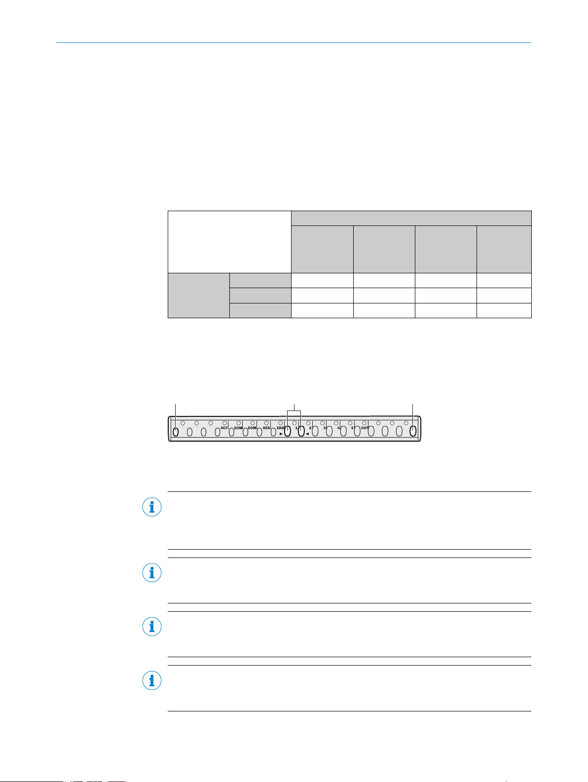
! ""
7 CONFIGURATION
Further topics
"Ext
•
•
7.3.3 Deactivating reset and EDM
Overview
D
eactivating reset and EDM resets both twin sticks back to their factory settings.
The following table shows when the configuration of a twin stick must be deactivated.
Table 9: Overview of in which cases deactivating the configuration is necessary for cascading
systems
The twin stick
w
ured with:
ernal device monitoring (EDM)", page 34
"Deactivating reset and EDM", page 66
as config‐
The twin stick should be used as a:
Single system
t in pro‐
or hos
tective opera‐
tion
Unconfigured – – – –
Reset
EDM
C
C C
Single system
or host in pro‐
tective opera‐
tion with reset
–
Single system
or host in pro‐
tective opera‐
tion with EDM
C
– –
Guest
–
To deactivate the configuration, the optics in the center (! be
tween the two triangular
marks) or outside (") must be covered in a certain order. You have up to 30 s for each
of the following steps.
The COM LED (Ö white) is used as a timer for interrupting and releasing the protective
field.
Figure 57: Intervention points when deactivating configuration
Important information
NOTE
ince the system positions (host, guest 1 or guest 2) of a cascaded systems are only
S
determined via the system plug and saving is not done in EEPROM, it is necessary to
deactivate the system position.
NOTE
he device is to be used as a host of a cascaded system or as a single system, in each
If t
case without reset and/or EDM, resetting and/or EDM must be deactivated.
66
NOTE
If t
he device is to be used as a guest of a cascaded system, deactivating the configura‐
tion is not necessary.
NOTE
If the COM LED lights up white two times in succession during deactivation of the con‐
figuration, the procedure has been canceled. In this case, restart from step 1.
O PE R AT I NG IN S TR U CT I ON S | miniTwin4 8012624/10OM/2018-08-09 | SICK
Subject to change without notice
Page 67

CONFIGURATION 7
Prerequisites
T
he system or machine is in a non-dangerous state.
•
The twin sticks are aligned. LEDs 1 to 5 (O blue) show the alignment quality. At
•
least 3 of the 5 LEDs must light up so that the configuration can be deactivated.
Approach
1.
Switch the safety light curtain off and then back on and begin deactivation within
2 min.
2. Interrupt the protective field of the safety light curtain until the COM LED flashes
white once (after about 3 s).
3. Stop the interruption within the next 30 s.
4.
Keep the protective field of the safety light curtain clear until the COM LED flashes
white once (after about 3 s).
5. Within the next 30 s, interrupt the protective field of the safety light curtain again
he center until the COM LED flashes white once (after about 3 s).
in t
6. Stop the interruption within the next 30 s.
✓
T
he run direction of LEDs 1 to 5 (Ö blue) points outwards; it points to the next
interruption.
7. Keep the protective field of the safety light curtain clear until the COM LED flashes
white once (after about 3 s).
8. Within the next 30 s, interrupt the protective field of the safety light curtain exter‐
nall
y until the COM LED flashes white once (after about 3 s).
9. Stop the interruption within the next 30 s.
✓
he run direction of LEDs 1 to 5 (Ö blue) points inwards; it points to the next
T
interruption in the center.
10. Keep the protective field of the safety light curtain clear until the COM LED flashes
white once (after about 3 s).
8012624/10OM/2018-08-09 | SICK O PE R AT I NG IN S TR U CT I ON S | miniTwin4
Subject to change without notice
67
Page 68

7 C
ONFIGURATION
11. Within the next 30 s, interrupt the protective field of the safety light curtain again
in the center until the COM LED flashes white once (after about 3 s).
12. Stop the interruption within the next 30 s.
✓
he run direction of LEDs 1 to 5 (Ö blue) points outwards; it points to the next
T
interruption.
13. Keep the protective field of the safety light curtain clear until the COM LED flashes
white once (after about 3 s).
14. Within the next 30 s, interrupt the protective field of the safety light curtain exter‐
nall
y until the COM LED flashes white once (after about 3 s).
15. Stop the interruption within the next 30 s.
16.
Keep the protective field of the safety light curtain clear until the COM LED flashes
white and LEDs 1 to 5 flash blue three times (after about 3 s).
17. Switch off the safety light curtain within the following 2 min.
✓
EDM or r
18. After deactivating the configuration, check the wiring and adjust it to the desired
function if necessary.
19. If EDM or reset must be reactivated after deactivating the configuration, the
desired configuration must be repeated.
20. Check the effectiveness of the protective device.
Further topics
eset is deactivated at the next switch-on.
7.4 Cascading
68
O PE R AT I NG IN S TR U CT I ON S | miniTwin4 8012624/10OM/2018-08-09 | SICK
"C
onfiguring reset", page 64
•
"Configuring external device monitoring (EDM)", page 65
•
"Testing plan", page 40
•
Overview
A ma
ximum of 3 safety light curtains can be connected into a cascaded system.
Subject to change without notice
Page 69
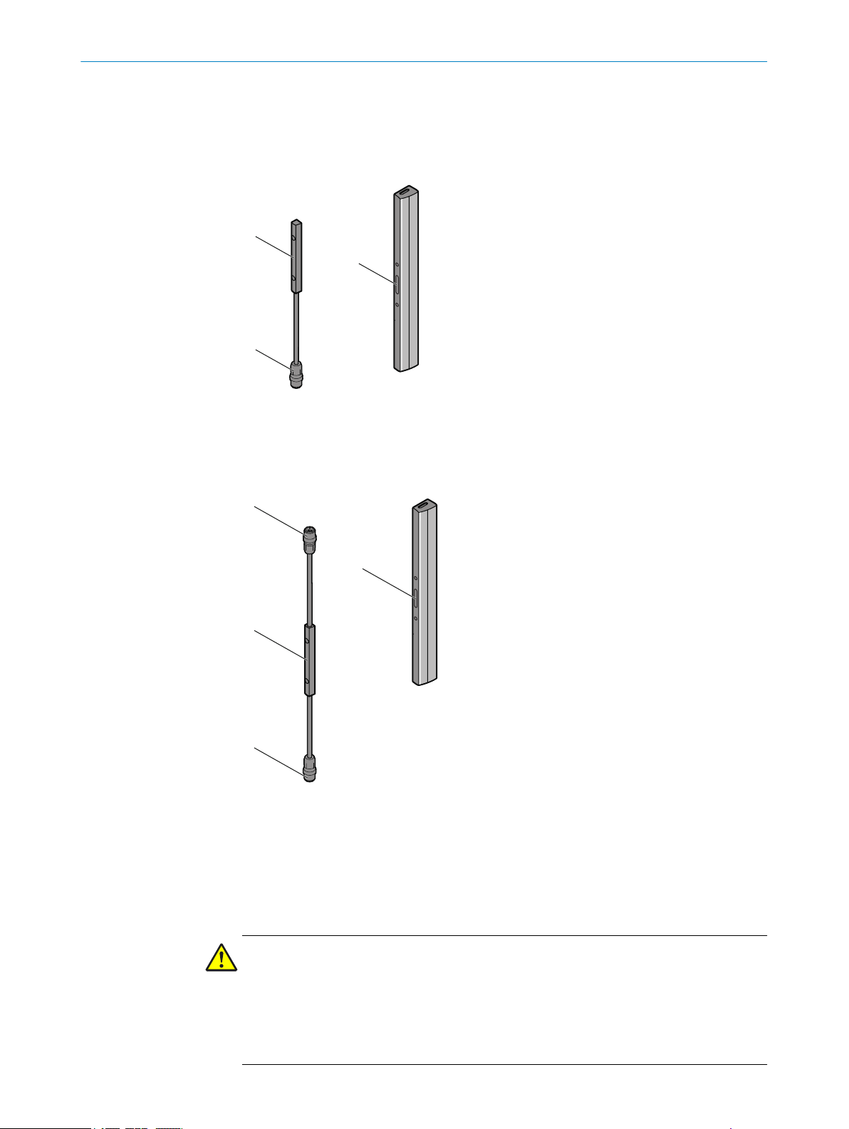
!
"
§
!
$
"
§
CONFIGURATION 7
The following system plugs are available for cascading:
S
ystem plug for single systems with an M12×4 + FE system connection (male con‐
•
nector)
System plug for cascaded systems with an M12×4 + FE system connection (male
•
connector) and an M12×4 + FE extension connection (female connector)
Figure 58: System plug with system connection
System plug
!
System connection
"
Device connection
§
Figure 59: System plug with system connection and extension connection
Extension connection
!
System plug
"
System connection
§
Device connection
$
Important information
DANGER
k of ineffectiveness of the protective device
Ris
The length of cable between 2 cascaded systems must not exceed 3 m.
Use the shortest possible cables between the devices of a cascaded system.
b
Protect the cascaded system from manipulation with an optimized length of cable
b
or with cable routing under a cover.
8012624/10OM/2018-08-09 | SICK O PE R AT I NG IN S TR U CT I ON S | miniTwin4
Subject to change without notice
69
Page 70
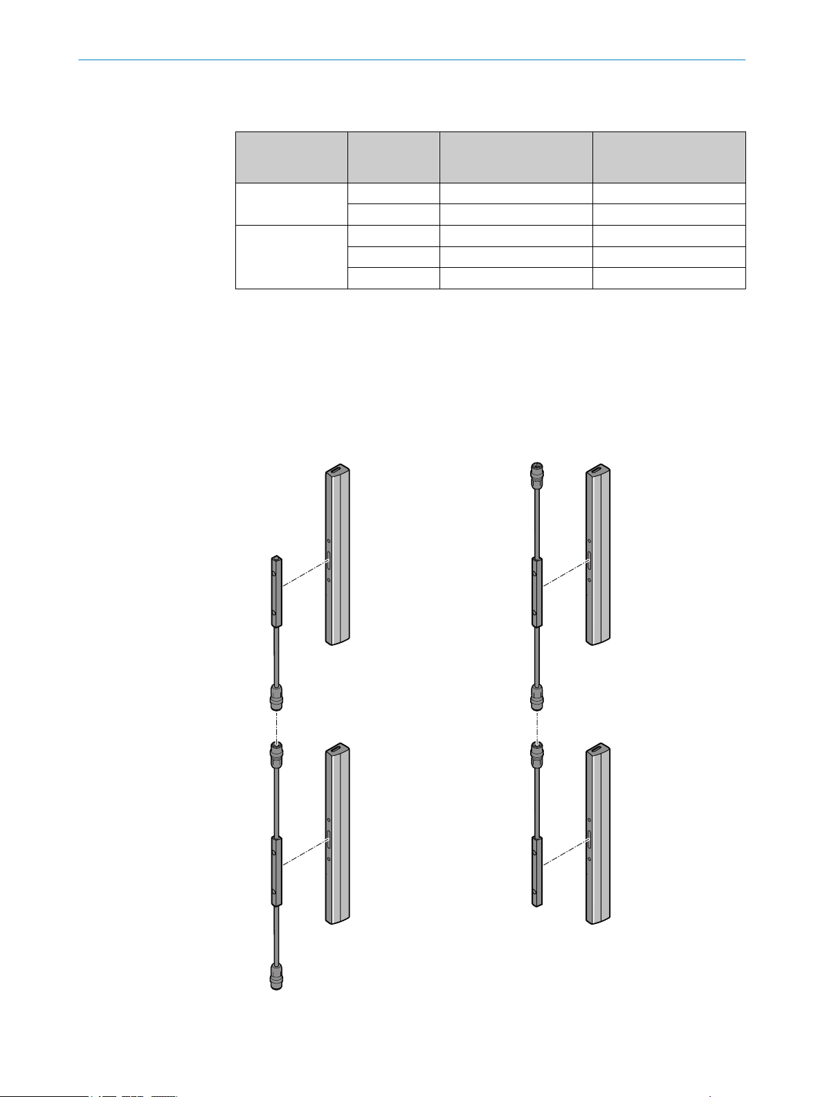
!
"
§
$
7 CONFIGURATION
Use of system plugs in a cascade
T
able 10: Use of system plugs in a cascade
Cascade with one
st
gue
Cascade with two
guest devices
✓
System plug suitable.
–
System plug not suitable.
Device type System plug with system
c
onnection
Host –
Guest 1
Host –
Guest 1 –
Guest 2
✓
✓
System plug with system
connection and extension
connection
✓
–
✓
✓
–
A cascaded system with several safety light curtains is configured solely through the
se
lection of the system plug (single system or cascade) and its cabling. No other action
is necessary.
Complementary information
Both system plugs (system plugs for single systems and system plugs for cascaded sys‐
tems) can be rotated by 180° on the device connection.
70
Figure 60: Mounting the system plugs on a cascaded system
System plug for single systems
!
O PE R AT I NG IN S TR U CT I ON S | miniTwin4 8012624/10OM/2018-08-09 | SICK
Subject to change without notice
Page 71
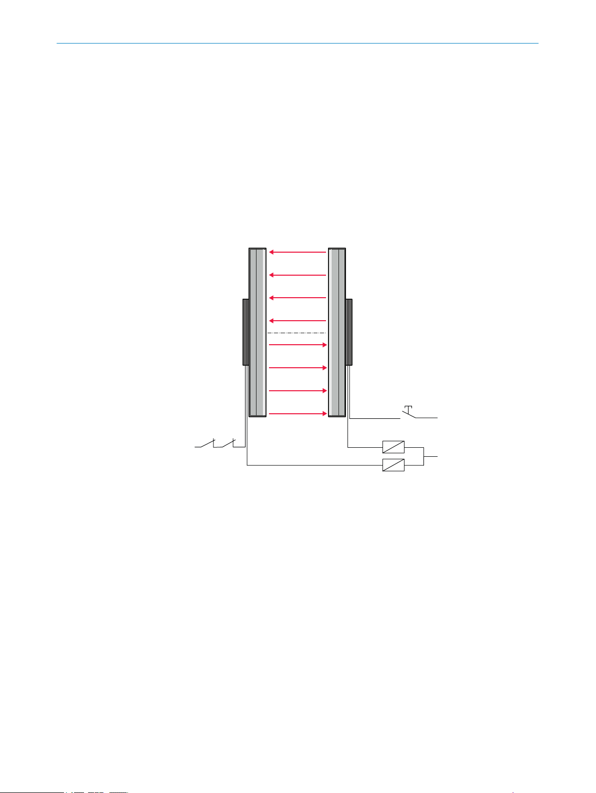
System plug for cascaded systems
!
O
S
SD1
EDM
k
2
24 V
DC
k
1
0
V
DC
K1
K2
O
SSD2
"
System plug for cascaded systems, rotated by 180°
§
System plug for single systems, rotated by 180°
$
7.4.1 Cascading new devices
Approach
1. Install and wire the devices.
2. Switch on the voltage supply.
3. If external device monitoring is connected correctly, it is configured automatically
and the EDM LED lights up orange.
4. To configure the restart interlock, press the reset pushbutton for between 1 and
3 s, then release it. The RES LED flashes orange.
✓
The cascade is in operation.
CONFIGURATION 7
Figure 61: Configurable functions
Reset button
!
Further topics
onfiguring beam coding", page 63
"C
•
7.4.2 Connecting a new device in an existing cascade
Overview
If an unconf
igured device is used, it may be necessary to manually configure the RES.
EDM is automatically detected and saved. The configuration of a cascade device is
done using the plug.
Approach
1. Install and wire the device.
2. Switch on the voltage supply.
3. If a host twin stick is exchanged, it may be necessary to reconfigure EDM or RES.
✓
The device is in operation.
8012624/10OM/2018-08-09 | SICK O PE R AT I NG IN S TR U CT I ON S | miniTwin4
Subject to change without notice
71
Page 72
7 C
ONFIGURATION
Further topics
"C
onfiguring reset", page 64
•
"Configuring external device monitoring (EDM)", page 65
•
7.4.3 Cascading pre-configured devices
Overview
T
he individual safety light curtains can be used as single systems after disconnecting
them from the cascaded systems if they are connected via a system plug for single sys‐
tems.
If a device that may have already been configured is used to extend a cascade or
replace a (defective) device in a cascade, it may need to be reset.
Table 11: Overview of in which cases deactivating the configuration is necessary for cascading
systems
The twin stick
as config‐
w
ured with:
Unconfigured – – – –
Reset
EDM
Single system
t in pro‐
or hos
tective opera‐
tion
C
C C
The twin stick should be used as a:
Single system
or host in pro‐
tective opera‐
tion with reset
–
Single system
or host in pro‐
tective opera‐
tion with EDM
C
– –
Guest
–
Important information
DANGER
Danger caused by ineffectiveness of protective device
Check the effectiveness of the protective device after every change to the system.
b
Approach
1.
Install and wire the device.
2. If necessary, reset the devices to be used as hosts, see table 9.
3. With the present wiring, reconfigure EDM (automatic) or RES (manual) on the host
on the twin stick, if necessary.
4. Switch on the voltage supply.
✓
The device is in operation.
Further topics
"Configuring beam coding", page 63
•
"Test rod check", page 41
•
7.5 Status indication on both sides
The OSSD status and the status of the protective field are indicated via LEDs on every
t
win stick.
72
O PE R AT I NG IN S TR U CT I ON S | miniTwin4 8012624/10OM/2018-08-09 | SICK
Subject to change without notice
Page 73
8 Commissioning
8.1 Safety
Important information
DANGER
H
azard due to lack of effectiveness of the protective device
When changes are made to the machine, the effectiveness of the protective device may
be affected unintentionally.
After every change to the machine and changes to the integration or operational
b
and secondary conditions of the safety light curtain, check the protective device
for effectiveness and recommission as specified in this chapter.
DANGER
Dangerous state of the machine
Make sure that the dangerous state of the machine is (and remains) switched off
b
during mounting, electrical installation, and commissioning.
Make sure that the outputs of the safety light curtain do not affect the machine
b
during mounting, electrical installation, and commissioning.
COMMISSIONING 8
8.2 Overview
DANGER
azard due to lack of effectiveness of the protective device
H
Before commissioning the machine, make sure that the machine is first checked
b
and released by qualified safety personnel.
Only operate the machine with a perfectly functioning protective device.
b
Further topics
"Minimum dis
•
Prerequisites
Pr
oject planning has been completed correctly
•
Mounting has been completed correctly
•
Electrical installation has been completed correctly
•
Approach
1. If required, connect up to 3 devices to a cascade.
2. Mount the system plug.
3. Switch on the voltage supply.
If the device is set to the factory settings, the OUT LED lights up green.
°
If the configuration does not match the wiring, the device display an error.
°
4. Configure the restart interlock if required. EDM is automatically configured.
5. If the configuration of the host for the restart interlock or external device monitor‐
ing needs to be changed, reset the two twin sticks to factory settings.
6. After configuration is complete, align both twin sticks.
7. If 3 of the 5 blue LEDs light up, the safety light curtain switches to green. From this
point in time, you have about 2 min to optimize the alignment of the twin stick.
8. Check alignment.
9. Check the protective device.
tance from reflective surfaces", page 25
8012624/10OM/2018-08-09 | SICK O PE R AT I NG IN S TR U CT I ON S | miniTwin4
Subject to change without notice
73
Page 74

8 C
OMMISSIONING
Further topics
"Pr
•
•
•
•
•
•
•
•
oject planning", page 21
"Mounting", page 44
"Electrical installation", page 60
"Configuration", page 63
"Mounting the system plug", page 45
"Configuring reset", page 64
"Alignment of the twin stick", page 74
"Check during commissioning and modifications", page 77
8.3 When it is switched on
Overview
NOTE
th twin sticks must always be switched on at the same time. When one of the twin
Bo
sticks is taken out of operation, the second twin stick must be switched off briefly
before switching on again.
After the safety light curtain is switched on, it goes through the power-up cycle. The
LEDs indic
ate the device status during the power-up cycle.
The LEDs have the following meanings:
Table 12: LEDs during power-up cycle
LED Meaning
O All LEDs
O R
ed
Ö W
hite
Ö W
hite O Blue 1
O Blue 1 t
O Gr
O Or
O Or
Other display Device error
o 5
een
ange RES
ange EDM
LED test. All LEDs light up briefly.
OSSD off, system is being activated
No optical communication to another twin stick
)
1
Communication to the second twin stick is
g established
bein
Alignment quality display (goes out when suffi‐
gnment quality exists for 2 min)
cient ali
OSSD off, system active, protective field free
RES configured
EDM configured
Further topics
ations when switching on", page 83
"Indic
•
"Configuring reset", page 64
•
"Configuring external device monitoring (EDM)", page 65
•
"Fault indicators", page 86
•
8.4 Alignment of the twin stick
Overview
Onc
e mounting and electrical installation are complete, the twin sticks must be aligned
with each other.
1)
74
ing the initial commissioning of a twin stick, the LED flashes immediately to signal the first synchronization between the twin sticks.
Dur
For all other power-up processes, the LED only flashes if the previous system partner does not answer within 20 s. In this case, communi‐
cation can also be established with a replacement twin stick.
O PE R AT I NG IN S TR U CT I ON S | miniTwin4 8012624/10OM/2018-08-09 | SICK
Subject to change without notice
Page 75

Important information
! " §
LED 1, 2, 3, 4, 5
LED 1, 2, 3
DANGER
angerous state of the machine
D
Make sure that the dangerous state of the machine is (and remains) switched off
b
during the alignment process.
Make sure that the outputs of the safety light curtain do not affect the machine
b
during the alignment process.
NOTE
Dur
ing the alignment, observe the alignment quality indication and the bracket that is
used to attach the twin sticks.
Further topics
gning the twin sticks to one another", page 75
"Ali
•
"Indication of the alignment quality", page 77
•
"Diagnostic LEDs", page 83
•
8.4.1 Aligning the twin sticks to one another
COMMISSIONING 8
Overview
Af
ter the safety light curtain has been mounted and connected, the two twin sticks
must be aligned with each other. The beams of the sender optics must met exactly on
the receiver optics.
The miniTwin4 safety light curtain signals the alignment quality with the blue LEDs (1 to
5), i.e. how well the two twin sticks are aligned with each other. If all LEDs light up, then
alignment is optimal; if no LEDs light up, alignment is poor.
If 3 of the blue LEDs light up, the safety light curtain switches to green. From this point
in time, you have about 2 minutes to optimize the alignment of the twin stick.
8012624/10OM/2018-08-09 | SICK O PE R AT I NG IN S TR U CT I ON S | miniTwin4
Subject to change without notice
Figure 62: Alignment of the safety light curtain
Optimal alignment
!
Sufficient alignment
"
Insufficient alignment
§
75
Page 76

8 C
OMMISSIONING
Important information
DANGER
angerous state of the machine
D
Make sure that the dangerous state of the machine is (and remains) switched off
b
during the alignment process.
Make sure that the outputs of the safety light curtain do not affect the machine
b
during the alignment process.
Prerequisites
T
he twin sticks are correctly mounted
•
Approach
1. Switch on the voltage supply for the safety light curtain.
✓
During initial commissioning, the COM LED flashes white and the two twin sticks
establish communication 2).
2. Align the two twin sticks with one another so that LED 1 lights up blue as well.
✓
The two twin sticks start communicating with one another. During initial commis‐
sioning, the COM LED goes out after the communication phase (about 3 s). The
alignment can now be optimized.
3. Align the two twin sticks with one another so that at least 3 but as many as possi‐
ble of LEDs 1 to 5 light up blue.
In a cascaded system, the host remains red even if the alignment is sufficient until
all guest are sufficiently aligned.
When the maximum protective field width is utilized, the system might show mod‐
erate alignment quality during alignment with only 3 blue LEDs. The system still
has a reserve of 30 %.
4. If the alignment quality is sufficient for 2 min, the system switches alignment
mode off. LEDs 1 to 5 go out.
5. If the alignment needs to be redone, switch the voltage supply of both twin sticks
off and back on and continue from step 2.
6. Finally, fasten the safety light curtain.
✓
The alignment of the twin sticks is complete.
Complementary information
In some cases, the AR60 optional laser alignment aid can make performing the align‐
ment even easier.
Further topics
"Indication of the alignment quality", page 77
•
"Mounting", page 44
•
"Accessories", page 101
•
2)
76
ing the initial commissioning of a stick, the LED flashes immediately to signal the first synchronization between the sticks. For all
Dur
other power-up processes, the LED only flashes if the previous system partner does not answer within 20 s. In this case, communication
can also be established with a replacement stick.
O PE R AT I NG IN S TR U CT I ON S | miniTwin4 8012624/10OM/2018-08-09 | SICK
Subject to change without notice
Page 77

8.4.2 Indication of the alignment quality
Important information
NOTE
Once 3 blue alignment quality light emitting diodes light up, alignment is good and
availability is stable.
Please note that body parts or objects in the protective field (e.g., hand, tool, AR60
optional laser alignment aid) may impair the function of the alignment quality LEDs.
Remove all objects from the protective field to allow the alignment quality to be
assessed.
8.5 Check during commissioning and modifications
The check must detect if it is possible to enter the hazardous area without being
tected.
de
C
arry out the checks according to the instructions from the manufacturer of the
b
machine and from the operating entity.
COMMISSIONING 8
8012624/10OM/2018-08-09 | SICK O PE R AT I NG IN S TR U CT I ON S | miniTwin4
Subject to change without notice
77
Page 78

9 O
PERATION
9 Operation
9.1 Safety
DANGER
H
azard due to lack of effectiveness of the protective device
Persons and parts of the body to be protected may not be recognized in case of nonobservance.
Maintenance work, alignment work, fault diagnoses, and any changes to the inte‐
b
gration of the protective device in the machine must only be carried out by quali‐
fied personnel.
The effectiveness of the protective device must be checked following such work.
b
DANGER
H
azard due to lack of effectiveness of the protective device
Persons and parts of the body to be protected may not be recognized in case of nonobservance.
Make sure that the optical properties of the front screens of the twin sticks are not
b
changed, e.g., by:
beading water, mist, frost, or ice formation. If applicable, remove films or
°
other types of contamination, disconnect the voltage supply of the twin stick
and then switch it back on.
Scratches or damage. Replace the device if the front screen is scratched or
°
damaged.
Make sure that all reflective surfaces and objects maintain a minimum distance
b
from the protective field.
Make sure that no dispersive media (e.g., dust, fog, or smoke) are within the calcu‐
b
lated minimum distance from the protective field.
NOTE
This document does not provide information on operating the machine in which the
safety light curtain is integrated.
Further topics
"Minimum dis
•
9.2 Regular thorough check
The check must detect if it is possible to enter the hazardous area without being
de
tected. Such possibilities may exist due to modifications, manipulations or external
influences.
C
arry out the checks according to the instructions from the manufacturer of the
b
machine and from the operating entity.
tance from reflective surfaces", page 25
78
O PE R AT I NG IN S TR U CT I ON S | miniTwin4 8012624/10OM/2018-08-09 | SICK
Subject to change without notice
Page 79

9.3 LEDs
!
!
!
!
!
!
!
!
180 mm
300 mm
120 mm
240 mm
&
"
§
$
%
OPERATION 9
Figure 63: LEDs on the twin sticks
!
"
§
$
%
&
OUT
EDM
COM
RES
ERR
1, 2, 3, 4, 5
figure 7 sho
ular intervals above a protective field height of 180 mm and can light up red or green. It
is only labeled OUT in two locations on the safety light curtain.
ws the LEDs of the safety light curtain. The OUT LED (!) is mounted at reg‐
8012624/10OM/2018-08-09 | SICK O PE R AT I NG IN S TR U CT I ON S | miniTwin4
Subject to change without notice
79
Page 80

9 O
PERATION
Lit up LEDs indicate a specific status of the safety light curtain. Flashing LEDs demand
ac
tion.
Table 13: Meaning of LEDs
Position LED Display Comment
!
"
§
$
%
&
OUT
EDM
COM
RES
ERR
1, 2, 3, 4, 5
O Green
O Red
O Or
ange
Ö Or
ange
hite
O W
Ö W
hite
O Or
ange
Ö Or
ange
O Red
Ö R
ed
O Blue
Ö Blue In combination with ERR-LED Ö r
LED lights up green when protective field is free
SSD on).
(O
LED lights up red when protective field is inter‐
upted (OSSD off).
r
External device monitoring configured.
For the configuration of EDM at the first OSSD sta‐
us change, the safety light curtain expects the
t
change from 24 V to 0 V at the multifunctional
input.
Or:
In combination with the ERR-LED Ö red: External
device monitoring reports defective contactor
External communication active (e.g. for service)
No optical communication to another twin stick .
Or:
eedback when deactivating configuration.
F
Reset configured.
Reset configured.
Or:
In combina
Ö orange: error with configuration or cabling.
Protective field interrupted.
Error.
Indication of the alignment quality.
error.
tion with ERR-LED Ö red and EDM-LED
ed: display of an
o LED of
f. Ö LED flashes. O LED illuminates.
80
O PE R AT I NG IN S TR U CT I ON S | miniTwin4 8012624/10OM/2018-08-09 | SICK
Subject to change without notice
Page 81

10 Maintenance
The safety light curtain is maintenance-free. Depending on the ambient conditions, reg‐
ular c
10.1 Safety
DANGER
H
azard due to lack of effectiveness of the protective device
Persons and parts of the body to be protected may not be recognized in case of nonobservance.
Do not do repair work on device components.
b
Do not make changes to or manipulate device components.
b
Apart from the procedures described in this document, the device components
b
must not be opened.
10.2 Regular cleaning
Overview
MAINTENANCE 10
leaning is required.
D
epending on the ambient conditions of the safety light curtain, the front screens must
be cleaned regularly and in the event of contamination. Static charges can cause dust
particles to be attracted to the front screen. The weld spark guard and deflector mirrors
must be cleaned regularly and in the event of contamination.
Important information
DANGER
H
azard due to lack of effectiveness of the protective device
Persons and parts of the body to be protected may not be recognized in case of nonobservance.
Regularly check the degree of contamination on all components based on the
b
application conditions.
Observe the information concerning test rod testing.
b
DANGER
H
azard due to lack of effectiveness of the protective device
Persons and parts of the body to be protected may not be recognized in case of nonobservance.
Make sure that the optical properties of the front screens of the twin sticks are not
b
changed, e.g., by:
beading water, mist, frost, or ice formation. If applicable, remove films or
°
other types of contamination, disconnect the voltage supply of the twin stick
and then switch it back on.
Scratches or damage. Replace the device if the front screen is scratched or
°
damaged.
Make sure that all reflective surfaces and objects maintain a minimum distance
b
from the protective field.
Make sure that no dispersive media (e.g., dust, fog, or smoke) are within the calcu‐
b
lated minimum distance from the protective field.
8012624/10OM/2018-08-09 | SICK O PE R AT I NG IN S TR U CT I ON S | miniTwin4
Subject to change without notice
81
Page 82

10 MAINTENANCE
DANGER
azard due to unexpected starting of the machine
H
Make sure that the dangerous state of the machine is and remains switched off
b
during the cleaning.
Make sure that the outputs of the safety light curtain do not affect the machine
b
during the cleaning process.
NOTICE
D
o not use any aggressive cleaning agents.
b
Do not use any abrasive cleaning agents.
b
We recommend anti-static cleaning agents.
b
We recommend the use of anti-static plastic cleaner (SICK part number 5600006)
b
and the SICK lens cloth (SICK part number 4003353).
Approach
Remove dust from the front screen using a soft, clean brush.
1.
2. Then wipe the front screen with a clean, damp cloth.
3. Check the position of the twin sticks after cleaning.
4. Check the effectiveness of the protective device.
Further topics
"Operation", page 78
•
"Minimum distance from reflective surfaces", page 25
•
10.3 Regular thorough check
The check must detect if it is possible to enter the hazardous area without being
de
tected. Such possibilities may exist due to modifications, manipulations or external
influences.
C
arry out the checks according to the instructions from the manufacturer of the
b
machine and from the operating entity.
82
O PE R AT I NG IN S TR U CT I ON S | miniTwin4 8012624/10OM/2018-08-09 | SICK
Subject to change without notice
Page 83
11 Troubleshooting
11.1 Safety
DANGER
H
azard due to lack of effectiveness of the protective device
Persons and parts of the body to be protected may not be recognized in case of nonobservance.
Immediately shut the machine down if the behavior of the machine cannot be
b
clearly identified.
Immediately put the machine out of operation if you cannot clearly identify or allo‐
b
cate the fault and if you cannot safely remedy the fault.
Secure the machine so that it cannot switch on unintentionally.
b
DANGER
H
azard due to unexpected starting of the machine
When any work is taking place, use the protective device to secure the machine or
b
to ensure that the machine is not switched on unintentionally.
TROUBLESHOOTING 11
DANGER
azard due to lack of effectiveness of the protective device
H
Persons and parts of the body to be protected may not be recognized in case of nonobservance.
Do not do repair work on device components.
b
Do not make changes to or manipulate device components.
b
Apart from the procedures described in this document, the device components
b
must not be opened.
NOTE
dditional information on troubleshooting can be found at the responsible SICK sub‐
A
sidiary.
11.2 Diagnostic LEDs
11.2.1 Indications when switching on
Overview
NOTE
Bo
th twin sticks must always be switched on at the same time. When one of the twin
sticks is taken out of operation, the second twin stick must be switched off briefly
before switching on again.
After the safety light curtain is switched on, it goes through the power-up cycle. The
LEDs indic
ate the device status during the power-up cycle.
The LEDs have the following meanings:
Table 14: LEDs during power-up cycle
LED Meaning
O All LEDs
8012624/10OM/2018-08-09 | SICK O PE R AT I NG IN S TR U CT I ON S | miniTwin4
Subject to change without notice
LED test. All LEDs light up briefly.
83
Page 84

11 T
ROUBLESHOOTING
LED Meaning
O R
Ö W
ed
hite
OSSD off, system is being activated
No optical communication to another twin stick
)
3
Ö W
hite O Blue 1
O Blue 1 t
O Gr
O Or
O Or
Other display Device error
o 5
een
ange RES
ange EDM
Communication to the second twin stick is
g established
bein
Alignment quality display (goes out when suffi‐
gnment quality exists for 2 min)
cient ali
OSSD off, system active, protective field free
RES configured
EDM configured
Further topics
"Configuring reset", page 64
•
"Configuring external device monitoring (EDM)", page 65
•
"Fault indicators", page 86
•
3)
84
ing the initial commissioning of a twin stick, the LED flashes immediately to signal the first synchronization between the twin sticks.
Dur
For all other power-up processes, the LED only flashes if the previous system partner does not answer within 20 s. In this case, communi‐
cation can also be established with a replacement twin stick.
O PE R AT I NG IN S TR U CT I ON S | miniTwin4 8012624/10OM/2018-08-09 | SICK
Subject to change without notice
Page 85
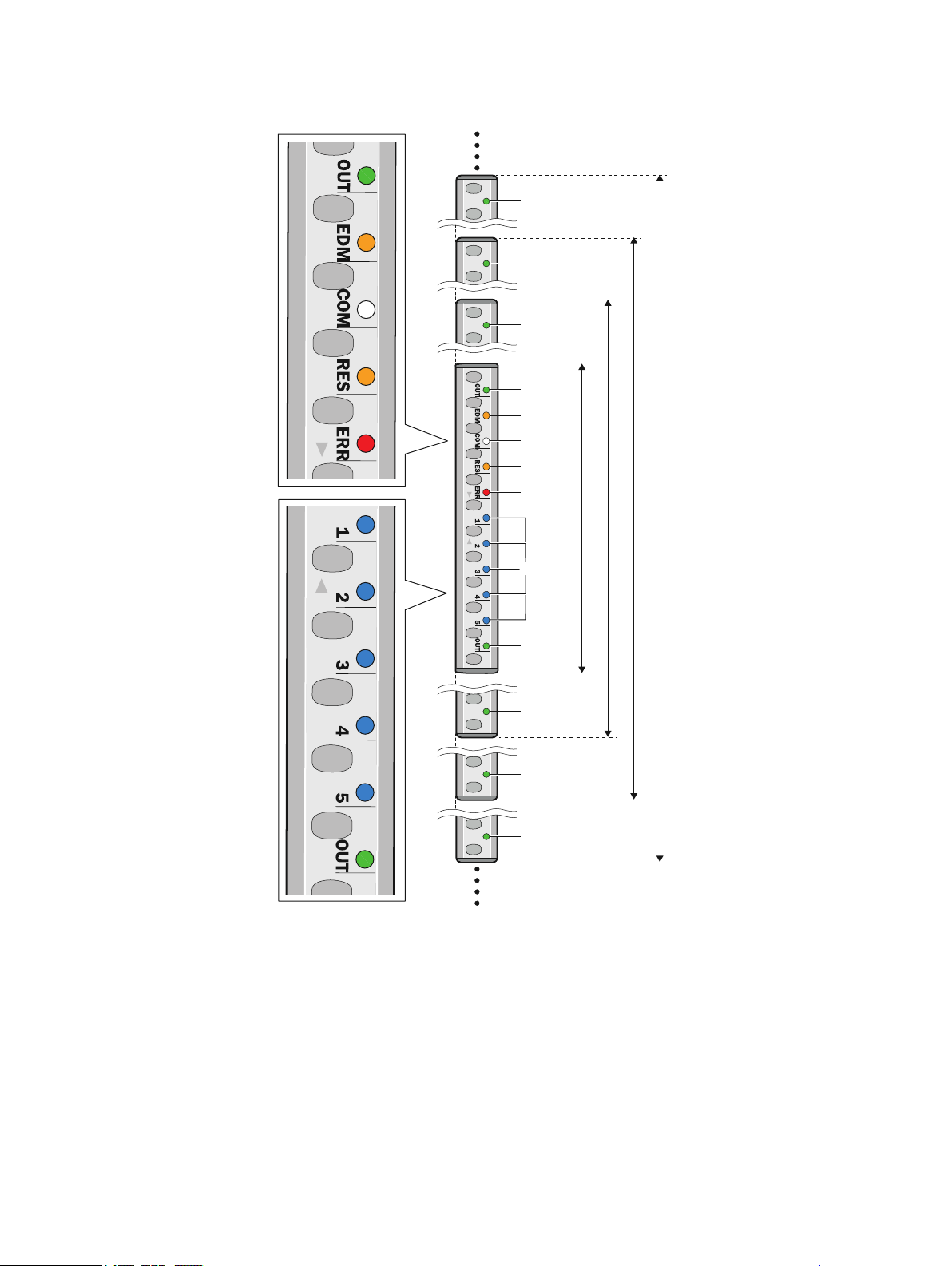
11.2.2 Status indicator
!
!
!
!
!
!
!
!
180 mm
300 mm
120 mm
240 mm
&
"
§
$
%
TROUBLESHOOTING 11
Figure 64: LEDs on the twin sticks
!
"
§
$
%
&
OUT
EDM
COM
RES
ERR
1, 2, 3, 4, 5
figure 7 sho
ular intervals above a protective field height of 180 mm and can light up red or green. It
is only labeled OUT in two locations on the safety light curtain.
ws the LEDs of the safety light curtain. The OUT LED (!) is mounted at reg‐
Lit up LEDs indicate a specific status of the safety light curtain. Flashing LEDs demand
action.
8012624/10OM/2018-08-09 | SICK O PE R AT I NG IN S TR U CT I ON S | miniTwin4
Subject to change without notice
85
Page 86

11 TROUBLESHOOTING
Table 15: Meaning of LEDs
Position LED Display Comment
!
"
§
$
%
&
OUT
EDM
COM
RES
ERR
1, 2, 3, 4, 5
O Gr
een
O Red
O Or
ange
Ö Or
ange
hite
O W
Ö W
hite
O Or
ange
Ö Or
ange
O Red
Ö R
ed
O Blue
Ö Blue In combination with ERR-LED Ö r
LED lights up green when protective field is free
SSD on).
(O
LED lights up red when protective field is inter‐
rupted (OSSD off).
External device monitoring configured.
For the configuration of EDM at the first OSSD sta‐
us change, the safety light curtain expects the
t
change from 24 V to 0 V at the multifunctional
input.
Or:
In combination with the ERR-LED Ö red: External
device monitoring reports defective contactor
External communication active (e.g. for service)
No optical communication to another twin stick .
Or:
eedback when deactivating configuration.
F
Reset configured.
Reset configured.
Or:
In combina
Ö orange: error with configuration or cabling.
Protective field interrupted.
Error.
Indication of the alignment quality.
error.
tion with ERR-LED Ö red and EDM-LED
ed: display of an
Further topics
11.2.3 Fault indicators
Overview
T
respond to them.
Table 16: LED fault indicators
o LED of
•
•
•
•
f. Ö LED flashes. O LED illuminates.
"Dia
gnostic LEDs", page 83
"Status indicators", page 17
"Aligning the twin sticks to one another", page 75
"Indication of the alignment quality", page 77
his section describes what the fault indicators of the diagnosis LEDs mean and how to
Display Possible cause Troubleshooting
Red ERR
Ö
Blue 1
Ö
Blue 2
o
Blue 3
o
Blue 4
o
Blue 5
o
System fault
S
witch the voltage supply of the miniTwin4 off
b
and back on (renewed power-up).
Check all plug connectors.
b
Check the FE connection.
b
Check the cable laying for interference (e.g.
b
EMC).
86
O PE R AT I NG IN S TR U CT I ON S | miniTwin4 8012624/10OM/2018-08-09 | SICK
Subject to change without notice
Page 87

Display Possible cause Troubleshooting
Red ERR
Ö
Blue 1
o
Blue 2
Ö
Blue 3
o
Blue 4
o
Blue 5
o
Red ERR
Ö
Blue 1
o
Blue 2
o
Blue 3
Ö
Blue 4
o
Blue 5
o
Red ERR
Ö
Blue 1
o
Blue 2
o
Blue 3
o
Blue 4
Ö
Blue 5
o
Red ERR
Ö
Blue 1
o
Blue 2
o
Blue 3
o
Blue 4
o
Blue 5
Ö
White COM Fault during com‐
Ö
Red ERR
Ö
Orange EDM
Ö
Red ERR
Ö
Orange EDM
Ö
Orange RES
Ö
Orange EDM
Ö
Orange RES
Ö
Short-circuit,
cr
oss-circuit or
cable defect
Supply voltage
oo low
t
Fault due to
ambient li
System error
munic
between 2 twin
sticks
EDM errors
Error during con‐
iguration of EDM
f
or reset or
cabling of Pin 2
Configuration of
EDM or r
yet performed.
ght
ation
eset not
Chec
b
b
b
b
b
b
b
b
b
b
b
b
b
b
b
b
b
k the function of the reset button. The
pushbutton may be defective or being pressed
continuously.
Check the wiring for short-circuit to 24 V or
0 V.
Check the wiring between host and guest or
between host, guest and guest.
Check the wiring between the two OSSDs.
Chec
k the supply voltage and the power sup‐
ply unit. Replace defective components if nec‐
essary.
Chec
k the distance to reflective surfaces or to
other safety light curtains. If necessary,
mount non-reflective partitions.
Switch the voltage supply of the miniTwin4 off
and back on (renewed power-up).
If the display also lights up during repeated
power-up during the start-up phase, replace
the device.
If the display lights up during operation, con‐
tact SICK support.
Chec
k the alignment of the two twin sticks
with one another.
Or, if a twin stick has been replaced:
Switch the voltage supply for both twin sticks
off and then back on again.
k the contactors and their wiring, fix the
Chec
wiring error if necessary.
R
epeat configuration of EDM or reset.
Or:
Check the cabling Pin 2.
S
witch on the connected relay or the contac‐
tor.
Or:
Actuate the connected reset button.
Or:
Check the cabling Pin 2.
TROUBLESHOOTING 11
Further topics
"St
•
•
•
•
•
8012624/10OM/2018-08-09 | SICK O PE R AT I NG IN S TR U CT I ON S | miniTwin4
Subject to change without notice
atus indicators", page 17
"Minimum distance from reflective surfaces", page 25
"Minimum distance for cascaded systems", page 26
"Configuring reset", page 64
"Protective operation without reset and/or without EDM", page 31
87
Page 88

12 DECOMMISSIONING
12 Decommissioning
12.1 Protection of the environment
The safety light curtain has been designed to minimize its impact on the environment. It
s only minimum of power and natural resources.
use
Always act in an environmentally responsible manner at work. Please note the fol‐
b
lowing information regarding disposal.
12.2 Disposal
Always dispose of serviceableness devices in compliance with local/national rules and
r
egulations with respect to waste disposal.
NOTE
W
e will be glad to help you dispose of these devices on request.
88
O PE R AT I NG IN S TR U CT I ON S | miniTwin4 8012624/10OM/2018-08-09 | SICK
Subject to change without notice
Page 89

13 Technical data
13.1 Data sheet
General system data
able 17: General system data
T
Protective field height, depending on
ype
t
Resolution (detection capability),
dependin
Scanning range 1)
With 1 additional front screen 0-3.7 m 0-4.6 m
With 2 additional front screens 0-3.4 m 0-4.2 m
With 1 deflector mirror
With 2 deflector mirrors
Protection class
Enclosure rating IP65 (IEC 60529)
Supply voltage UV a
Residual ripple
Type Type 4 (IEC 61496-1)
Category Category 4 (ISO 13849-1)
Performance level
Safety integrity level
SIL claim limit
PFHd (mean probability of a dangerous failure per hour)
Single system 4.3 x 10
Cascaded systems 13 x 10
TM (mis
Safe status when a fault occurs At least one OSSD is in the OFF state.
Power-up delay after supply voltage
applied
Wavelength 850 nm
Output signal switching devices
SSDs)
(O
Switching voltage
U
)
eff
Switching voltage LOW (deactivated) 0 V 0 V 2 V
Switching current 0 mA 300 mA
Single system leakage current
Cascaded system leakage current
Load capacity 1 µF
Switching sequence Depending on the load inductance
Load inductance
Test pulse data
Minimum Typical Maximum
120 mm to 1,200 mm
14, 24 or 34 mm
g on type
2)
3)
3)
4)
t the device
6)
7)
7)
7)
0-4.0 m 0-5.0 m
0-3.6 m 0-4.5 m
0-3.2 m 0-4.0 m
III (IEC 61140)
5)
19.2 V 24 V 28.8 V
PL e (ISO 13849–1)
ote the optical performance characteristics!
N
SIL3 (IEC 61508)
SILCL3 (IEC 62061)
–9
–9
sion time) 20 years (ISO 13849-1)
3 s
PNP semiconductor, short-circuit protected 9), cross-cir‐
cuit monitored
10) 11)
HIGH (active,
12)
13)
14)
Uv- 2.2 V 24 V U
12)
TECHNICAL DATA 13
±10%
8)
v
0.25 mA
0.5 mA
2.2 H
8012624/10OM/2018-08-09 | SICK O PE R AT I NG IN S TR U CT I ON S | miniTwin4
Subject to change without notice
89
Page 90

13 TECHNICAL DATA
Minimum Typical Maximum
Test pulse width 120 µs 150 µs 300 µs
Test pulse rate 3 s
-1
5 s
-1
10 s
-1
Permissible cable resistance 1.29 Ω
Current consumption 3 A (Host/Guest/
Gue
st)
15)
Multifunctional connection
Input voltage
10)
HIGH (deactivated) 11 V 24 V 30 V
Input current HIGH 6 mA 15 mA 30 mA
10)
Input voltage
OW (active) -3 V 0 V 5 V
L
Input current LOW -2.5 mA 0 mA 0.5 mA
When used as EDM input
Permissible contactor dropout time 300 ms
Permissible contactor pull in time 300 ms
When used as control switch input (reset button)
Control switch actuation time 200 ms
Weight Depends on protective field height
1)
The minimum scanning range specifies a range in which a function is guaranteed to operate correctly and
afely under industrial conditions. A sufficient level of signal reserve to ensure very high availability is
s
included in the calculation.
2)
The typical scanning range specifies a range in which the safety light curtain operates correctly and
safely under industrial conditions. The level of signal reserve is enough to ensure high availability.
3)
The information in the table relates to 90° beam deflection per mirror. If you need more consultation on
mirror applications, please contact your SICK contact. É Do not use deflector mirrors if beading water or
heavy contamination on the deflector mirror is to be expected.
4)
SELV/PELV safety/protective extra-low voltage.
5)
In order to fulfill the requirements of the relevant product standards (e.g. IEC 61496-1), the external volt‐
a
ge supply of the devices (SELV) must be able to bypass events, including a power outage of 20 ms. The
power supply unit must ensure reliable network separation (SELV/PELV) and current limiting of max. 4 A.
Power supply units according to EN 60204-1 fulfill this prerequisite. Suitable power supply units are avail‐
able as accessories from SICK.
6)
Within the limits of UV.
7)
For more detailed information on the exact configuration of your machine, please contact your relevant
SIC
K subsidiary.
8)
The performance level does not include any specific requirements regarding aspects such as optical per‐
formance features.
9)
Applies for the voltage range between -30 V and +30 V.
10)
According to IEC 61131-2.
11)
At the male device connector
12)
In the event of a fault (interruption of the 0 V cable), the leak current at most flows in the OSSD cable.
The downstream control element must detect this state as LOW. An FSPLC (fail-safe programmable logic
controller) must detect this state.
13)
If the switching sequence is low, the maximum permissible load inductance is higher.
14)
When active, the outputs are tested cyclically (brief LOW). When selecting the downstream controllers,
make sure that the test pulses do not result in deactivation when using the above parameters.
15)
Maximum current consumption of a system with 1200 mm protective field height and a resolution of
14 mm.
90
Operating data
T
able 18: Operating data
Minimum Typical Maximum
System connection M12×4 male connector + FE
Length of cable 20 m
Wire cross-section 0.34 mm
Bend radius 45 mm
O PE R AT I NG IN S TR U CT I ON S | miniTwin4 8012624/10OM/2018-08-09 | SICK
2
Subject to change without notice
Page 91

TECHNICAL DATA 13
Minimum Typical Maximum
Ambient operating temperature (UL/
C
SA: surrounding air temperature)
Air humidity (non-condensing) 15% 95%
Storage temperature -25 °C +70 °C
Housing cross-section 15 mm × 24 mm
Dimensions including male connec‐
or
t
Vibration resistance 5 g, 10–55 Hz (EN 60068-2-6)
Shock resistance 10 g/16 ms (EN 60068-2-27)
Housing, materials
T
able 19: Housing, materials
Dimensions Depending on type
Housing AlMgSi 0,5 (ENAWL6060 T6)
Front screen PC
Bracket Polyamide PA 66 GF30
End cap Polyamide PA 66 GF30
Printed circuit boards Glass fiber reinforced epoxy resin with flame retardant
System connection
External material of the cable TPU (PUR)
Packaging Corrugated cardboard with polyethylene
-20 °C +55 °C
15 mm × 32 mm
Material
TBBPA
Further topics
•
•
•
13.2 Response time
Overview
T
he response time depends on the following parameters:
•
•
•
•
Response time for a single device
Table 20: Response time for a single device
Response time of single device with
14 mm r
height 120 to 720 mm)
Response time of single device with
14 mm resolution (protective field
height 780 to 1,200 mm)
"Table of weights", page 92
"Accessories", page 101
"Dimensional drawings", page 94
Resolution
Protective field height
Beam coding
Number of cascaded devices
Minimum Typical Maximum
≤ 14 ms
esolution (protective field
≤ 17 ms
8012624/10OM/2018-08-09 | SICK O PE R AT I NG IN S TR U CT I ON S | miniTwin4
Subject to change without notice
91
Page 92

13 TECHNICAL DATA
Response time of single device with
24 or 34 mm r
Additional response time for cas‐
caded systems (host/guest)
Additional response time for cas‐
caded systems (host/guest/guest)
Power-down time
Power-up delay 200 ms
1)
According to IEC 61496-2.
13.3 Power consumption
Table 21: Power consumption
Protective field height in mm Maximum power consumption in W
120 2.5
180 2.5
240 2.5
300 3.1
360 3.1
420 3.7
480 3.7
540 4.3
600 4.3
660 4.9
720 4.9
780 5.5
840 5.5
900 6.1
960 6.1
1020 6.7
1080 6.7
1140 7.3
1200 7.3
1)
Power discharged again via the OSSDs depending on the connected OSSD load must be added to the
able values.
t
esolution
1)
Minimum Typical Maximum
≤ 13 ms
2 ms
4 ms
80 ms
1)
13.4 Table of weights
miniTwin4
able 22: Weight miniTwin4
T
Protective field height in mm Weight in g
120 50
180 75
240 95
300 115
360 135
92
O PE R AT I NG IN S TR U CT I ON S | miniTwin4 8012624/10OM/2018-08-09 | SICK
Subject to change without notice
Page 93

Protective field height in mm Weight in g
420 155
480 175
540 195
600 215
660 235
720 255
780 280
840 300
900 320
960 340
1020 360
1080 380
1140 400
1200 420
PNS75 and PNS125 deflector mirrors
TECHNICAL DATA 13
Table 23: Weight of PNS75 and PNS125 deflector mirrors
Mirror height in mm Weight in g
PNS75 PNS125
340 1035 1580
490 1435 2190
640 1850 2820
790 2270 3450
940 2680 4080
1090 3095 4710
1240 3510 5345
8012624/10OM/2018-08-09 | SICK O PE R AT I NG IN S TR U CT I ON S | miniTwin4
Subject to change without notice
93
Page 94

S
94
8,7
15
6,5
32
23,8
4
4,5
10
15
13 TECHNICAL DATA
13.5 Dimensional drawings
Figure 65: Dimensional drawing for the miniTwin4 (mm)
NOTE
Pr
otective field height S corresponds to the size of the safety light curtain.
94
O PE R AT I NG IN S TR U CT I ON S | miniTwin4 8012624/10OM/2018-08-09 | SICK
Subject to change without notice
Page 95

14 Ordering information
14.1 Scope of delivery
Scope of delivery of twin stick
win stick
T
•
System plug
•
Test rod with diameter corresponding to the resolution of the safety light curtain
•
Bracket: Depending on type selected (C-Fix and L-Fix or O-Fix). The C-Fix-Flex align‐
•
ment bracket is available as an accessory.
Safety note
•
Installation Instructions
•
Operating instructions for download: www.sick.com
•
14.2 Ordering information miniTwin4
Single device or cascade end devices
T
able 24: Ordering information for 14 mm resolution
Protective field height in mm Type code Part number
120 C4MT-01214ABB03BE0 1207094
180 C4MT-01814ABB03BE0 1207097
240 C4MT-02414ABB03DE0 1207098
300 C4MT-03014ABB03DE0 1207099
360 C4MT-03614ABB03DE0 1207100
420 C4MT-04214ABB03DE0 1207101
480 C4MT-04814ABB03DE0 1207102
540 C4MT-05414ABB03DE0 1207103
600 C4MT-06014ABB03FE0 1207104
660 C4MT-06614ABB03FE0 1207105
720 C4MT-07214ABB03FE0 1207106
780 C4MT-07814ABB03FE0 1207107
840 C4MT-08414ABB03FE0 1207108
900 C4MT-09014ABB03FE0 1207109
960 C4MT-09614ABB03FE0 1207110
1020 C4MT-10214ABB03FE0 1207111
1080 C4MT-10814ABB03FE0 1207112
1140 C4MT-11414ABB03FE0 1207113
1200 C4MT-12014ABB03FE0 1207114
ORDERING INFORMATION 14
Table 25: Ordering information for 24 mm resolution
Protective field height in mm Type code Part number
120 C4MT-01224ABB03BE0 1207222
180 C4MT-01824ABB03BE0 1207223
240 C4MT-02424ABB03DE0 1207224
300 C4MT-03024ABB03DE0 1207225
360 C4MT-03624ABB03DE0 1207227
420 C4MT-04224ABB03DE0 1207228
480 C4MT-04824ABB03DE0 1207229
8012624/10OM/2018-08-09 | SICK O PE R AT I NG IN S TR U CT I ON S | miniTwin4
Subject to change without notice
95
Page 96

14 ORDERING INFORMATION
Protective field height in mm Type code Part number
540 C4MT-05424ABB03DE0 1207230
600 C4MT-06024ABB03FE0 1207231
660 C4MT-06624ABB03FE0 1207232
720 C4MT-07224ABB03FE0 1207233
780 C4MT-07824ABB03FE0 1207234
840 C4MT-08424ABB03FE0 1207235
900 C4MT-09024ABB03FE0 1207236
960 C4MT-09624ABB03FE0 1207237
1020 C4MT-10224ABB03FE0 1207238
1080 C4MT-10824ABB03FE0 1207239
1140 C4MT-11424ABB03FE0 1207240
1200 C4MT-12024ABB03FE0 1207241
Table 26: Ordering information for 34 mm resolution
Protective field height in mm Type code Part number
120 C4MT-01234ABB03BE0 1207242
180 C4MT-01834ABB03BE0 1207243
240 C4MT-02434ABB03DE0 1207244
300 C4MT-03034ABB03DE0 1207245
360 C4MT-03634ABB03DE0 1207246
420 C4MT-04234ABB03DE0 1207247
480 C4MT-04834ABB03DE0 1207248
540 C4MT-05434ABB03DE0 1207249
600 C4MT-06034ABB03FE0 1207250
660 C4MT-06634ABB03FE0 1207251
720 C4MT-07234ABB03FE0 1207252
780 C4MT-07834ABB03FE0 1207253
840 C4MT-08434ABB03FE0 1207254
900 C4MT-09034ABB03FE0 1207255
960 C4MT-09634ABB03FE0 1207256
1020 C4MT-10234ABB03FE0 1207257
1080 C4MT-10834ABB03FE0 1207258
1140 C4MT-11434ABB03FE0 1207259
1200 C4MT-12034ABB03FE0 1207260
96
Cascade devices
able 27: Ordering information for 14 mm resolution
T
Protective field height in mm Type code Part number
120 C4MT-01214ABB04BE0 1207115
180 C4MT-01814ABB04BE0 1207116
240 C4MT-02414ABB04DE0 1207117
300 C4MT-03014ABB04DE0 1207118
360 C4MT-03614ABB04DE0 1207119
420 C4MT-04214ABB04DE0 1207120
O PE R AT I NG IN S TR U CT I ON S | miniTwin4 8012624/10OM/2018-08-09 | SICK
Subject to change without notice
Page 97

ORDERING INFORMATION 14
Protective field height in mm Type code Part number
480 C4MT-04814ABB04DE0 1207121
540 C4MT-05414ABB04DE0 1207122
600 C4MT-06014ABB04FE0 1207123
660 C4MT-06614ABB04FE0 1207124
720 C4MT-07214ABB04FE0 1207125
780 C4MT-07814ABB04FE0 1207126
840 C4MT-08414ABB04FE0 1207127
900 C4MT-09014ABB04FE0 1207128
960 C4MT-09614ABB04FE0 1207129
1020 C4MT-10214ABB04FE0 1207130
1080 C4MT-10814ABB04FE0 1207131
1140 C4MT-11414ABB04FE0 1207132
1200 C4MT-12014ABB04FE0 1207133
Table 28: Ordering information for 24 mm resolution
Protective field height in mm Type code Part number
120 C4MT-01224ABB04BE0 1207168
180 C4MT-01824ABB04BE0 1207283
240 C4MT-02424ABB04DE0 1207284
300 C4MT-03024ABB04DE0 1207285
360 C4MT-03624ABB04DE0 1207286
420 C4MT-04224ABB04DE0 1207287
480 C4MT-04824ABB04DE0 1207181
540 C4MT-05424ABB04DE0 1207288
600 C4MT-06024ABB04FE0 1207289
660 C4MT-06624ABB04FE0 1207290
720 C4MT-07224ABB04FE0 1207291
780 C4MT-07824ABB04FE0 1207292
840 C4MT-08424ABB04FE0 1207293
900 C4MT-09024ABB04FE0 1207294
960 C4MT-09624ABB04FE0 1207295
1020 C4MT-10224ABB04FE0 1207296
1080 C4MT-10824ABB04FE0 1207297
1140 C4MT-11424ABB04FE0 1207298
1200 C4MT-12024ABB04FE0 1207299
Table 29: Ordering information for 34 mm resolution
Protective field height in mm Type code Part number
120 C4MT-01234ABB04BE0 1207300
180 C4MT-01834ABB04BE0 1207301
240 C4MT-02434ABB04DE0 1207302
300 C4MT-03034ABB04DE0 1207303
360 C4MT-03634ABB04DE0 1207304
420 C4MT-04234ABB04DE0 1207305
480 C4MT-04834ABB04DE0 1207306
8012624/10OM/2018-08-09 | SICK O PE R AT I NG IN S TR U CT I ON S | miniTwin4
Subject to change without notice
97
Page 98

14 ORDERING INFORMATION
Protective field height in mm Type code Part number
540 C4MT-05434ABB04DE0 1207307
600 C4MT-06034ABB04FE0 1207308
660 C4MT-06634ABB04FE0 1207309
720 C4MT-07234ABB04FE0 1207310
780 C4MT-07834ABB04FE0 1207311
840 C4MT-08434ABB04FE0 1207312
900 C4MT-09034ABB04FE0 1207313
960 C4MT-09634ABB04FE0 1207314
1020 C4MT-10234ABB04FE0 1207315
1080 C4MT-10834ABB04FE0 1207316
1140 C4MT-11434ABB04FE0 1207317
1200 C4MT-12034ABB04FE0 1206993
Single devices with O-Fix bracket
Table 30: Ordering information for 14 mm resolution
Protective field height in mm Type code Part number
120 C4MT-01214ABB03BB0 1206951
180 C4MT-01814ABB03BB0 1206945
240 C4MT-02414ABB03DB0 1206954
300 C4MT-03014ABB03DB0 1206953
360 C4MT-03614ABB03DB0 1206955
420 C4MT-04214ABB03DB0 1206956
480 C4MT-04814ABB03DB0 1206957
540 C4MT-05414ABB03DB0 1206958
600 C4MT-06014ABB03FB0 1206959
660 C4MT-06614ABB03FB0 1206960
720 C4MT-07214ABB03FB0 1206961
780 C4MT-07814ABB03FB0 1206962
840 C4MT-08414ABB03FB0 1206963
900 C4MT-09014ABB03FB0 1206964
960 C4MT-09614ABB03FB0 1206965
1020 C4MT-10214ABB03FB0 1206966
1080 C4MT-10814ABB03FB0 1206967
1140 C4MT-11414ABB03FB0 1206968
1200 C4MT-12014ABB03FB0 1206969
98
Table 31: Ordering information for 24 mm resolution
Protective field height in mm Type code Part number
120 C4MT-01224ABB03BB0 1207318
180 C4MT-01824ABB03BB0 1207177
240 C4MT-02424ABB03DB0 1207319
300 C4MT-03024ABB03DB0 1207320
360 C4MT-03624ABB03DB0 1207321
420 C4MT-04224ABB03DB0 1207322
O PE R AT I NG IN S TR U CT I ON S | miniTwin4 8012624/10OM/2018-08-09 | SICK
Subject to change without notice
Page 99

ORDERING INFORMATION 14
Protective field height in mm Type code Part number
480 C4MT-04824ABB03DB0 1207178
540 C4MT-05424ABB03DB0 1207323
600 C4MT-06024ABB03FB0 1207324
660 C4MT-06624ABB03FB0 1207325
720 C4MT-07224ABB03FB0 1207326
780 C4MT-07824ABB03FB0 1207327
840 C4MT-08424ABB03FB0 1207328
900 C4MT-09024ABB03FB0 1207329
960 C4MT-09624ABB03FB0 1207330
1020 C4MT-10224ABB03FB0 1207331
1080 C4MT-10824ABB03FB0 1207332
1140 C4MT-11424ABB03FB0 1207180
1200 C4MT-12024ABB03FB0 1207333
Table 32: Ordering information for 34 mm resolution
Protective field height in mm Type code Part number
120 C4MT-01234ABB03BB0 1207334
180 C4MT-01834ABB03BB0 1207335
240 C4MT-02434ABB03DB0 1207336
300 C4MT-03034ABB03DB0 1207337
360 C4MT-03634ABB03DB0 1207338
420 C4MT-04234ABB03DB0 1207339
480 C4MT-04834ABB03DB0 1207340
540 C4MT-05434ABB03DB0 1207341
600 C4MT-06034ABB03FB0 1207342
660 C4MT-06634ABB03FB0 1207343
720 C4MT-07234ABB03FB0 1207344
780 C4MT-07834ABB03FB0 1207345
840 C4MT-08434ABB03FB0 1207346
900 C4MT-09034ABB03FB0 1207347
960 C4MT-09634ABB03FB0 1207348
1020 C4MT-10234ABB03FB0 1207349
1080 C4MT-10834ABB03FB0 1207350
1140 C4MT-11434ABB03FB0 1207351
1200 C4MT-12034ABB03FB0 1207169
14.3 Weld spark guard
Overview
NOTE
2 addit
•
An additional front screen reduces the scanning range of the system by 7.5%. If 2
•
opposing twin sticks use an additional front screen, this reduces the scanning
range by 15%.
8012624/10OM/2018-08-09 | SICK O PE R AT I NG IN S TR U CT I ON S | miniTwin4
Subject to change without notice
ional front screens (weld spark guard) are supplied per part number.
99
Page 100

14 ORDERING INFORMATION
Table 33: Additional front screen (weld spark guard) part numbers
Protective field height in mm Part number
120 2058479
180 2058482
240 2058483
300 2058484
360 2058485
420 2058486
480 2058487
540 2058488
600 2058489
660 2058490
720 2058491
780 2058492
840 2058493
900 2058494
960 2058495
1020 2058496
1080 2058497
1140 2058498
1200 2058499
14.4 Alignment aid
Table 34: Alignment aid ordering information
Part Part number
Laser alignment aid AR60 1015741
Adapter 4064710
100
O PE R AT I NG IN S TR U CT I ON S | miniTwin4 8012624/10OM/2018-08-09 | SICK
Subject to change without notice
 Loading...