

Page 1

miniTwin2
Safety light curtain
OPERATING INSTRUCTIONS
en
Page 2

Operating Instructions
miniTwin2
This document is protected by the law of copyright, whereby all rights established therein remain with the
company SICK AG. Reproduction of this document or parts of this document is only permissible within the limits
of the legal determination of Copyright Law. Alteration or abridgement of the document is not permitted without
the explicit written approval of the company SICK AG.
2 © SICK AG • Industrial Safety Systems • Germany • All rights reserved 8013482/YT85/2016-02-23
Subject to change without notice
Page 3
Operating Instructions
miniTwin2
Device change history
Device change history
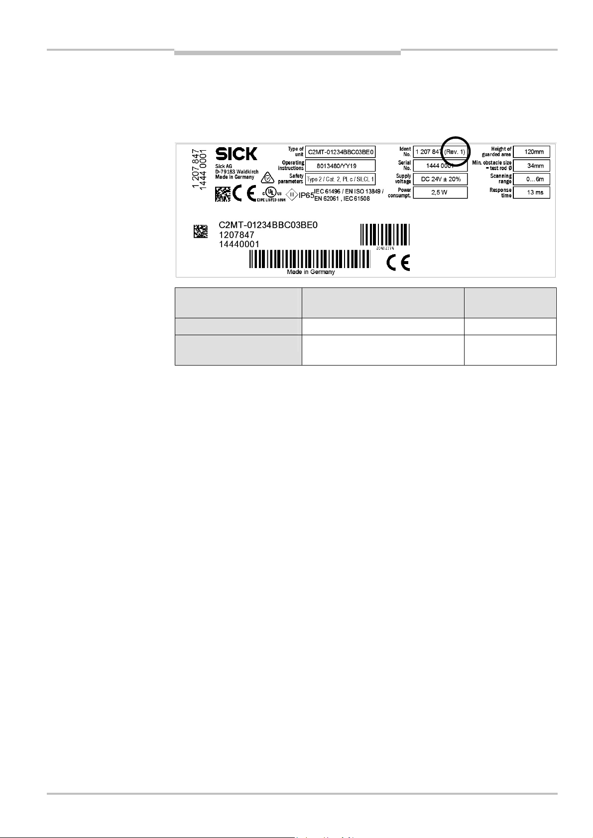
The following table describes technical changes that have been made to the device during
product updates. The change status of the device can be seen from the supplementary
revision number “(Rev. #)” in the Ident No. field on the type label.
Revision number in the
Ident No. field
No revision number Initial device version
(Rev. 1) Addition of the cross-circuit
Change Further information
monitoring function
Chapter 3.1,
page 11
8013482/YT85/2016-02-23 © SICK AG • Industrial Safety Systems • Germany • All rights reserved 3
Subject to change without notice
Page 4

Contents
miniTwin2
Operating Instructions
Contents
1 About this document ........................................................................................................ 6
1.1 Function of this document ................................................................................... 6
.2 Target group.......................................................................................................... 6
1
1.3 Scope..................................................................................................................... 6
1.4 Information depth................................................................................................. 6
1.5 Abbreviations ........................................................................................................ 7
1.6 Symbols used........................................................................................................ 7
2 On safety ............................................................................................................................ 8
2.1 Qualified safety personnel ................................................................................... 8
2.2 Applications of the device.................................................................................... 8
2.3 Correct use............................................................................................................ 9
2.4 General safety notes and protective measures.................................................. 9
2.5 Environmental protection................................................................................... 10
2.5.1 Disposal............................................................................................. 10
2.5.2 Separation of materials.................................................................... 10
3 Product description ........................................................................................................11
3.1 Special features.................................................................................................. 11
3.2 Operating principle of the device....................................................................... 12
3.2.1 Device components.......................................................................... 12
3.2.2 Operating principle safety light curtain ...........................................13
3.2.3 Cascading.......................................................................................... 14
3.3 Application examples ......................................................................................... 15
3.4 Status indicators................................................................................................. 16
3.5 Configurable functions .......................................................................................18
3.5.1 Reset ................................................................................................. 19
3.5.2 External device monitoring (EDM) ...................................................21
4 Mounting.......................................................................................................................... 22
4.1 Determining the minimum distance.................................................................. 22
4.1.1 Minimum distance from the hazardous point................................. 22
4.1.2 Minimum distance to reflective surfaces........................................ 25
4.1.3 Minimum distance for cascaded systems.......................................26
4.2 Steps for mounting the device........................................................................... 27
4.2.1 Mounting direction of the Twin Sticks ............................................. 28
4.2.2 Mounting possibilities ...................................................................... 28
4.2.3 Mounting with OAFix bracket ............................................................ 29
4.2.4 Mounting with CAFix bracket............................................................. 31
4.2.5 Mounting with LAFix bracket .............................................................33
4.2.6 Mounting with CAFix bracket and LAFix bracket ...............................35
4.2.7 Mounting with CAFix-Flex bracket ..................................................... 37
4.3 Resolution at the end of the Twin Sticks...........................................................40
5 Electrical installation .....................................................................................................41
5.1 System connection ............................................................................................. 43
5.1.1 Pin assignment system connection................................................. 44
5.2 Cascading............................................................................................................ 45
5.2.1 Changes to cascaded systems ........................................................ 46
5.3 Protective operation without Reset and/or without EDM ................................47
5.4 Reset button ....................................................................................................... 48
5.5 External device monitoring (EDM) .....................................................................49
5.6 Connection diagrams ......................................................................................... 50
4 © SICK AG • Industrial Safety Systems • Germany • All rights reserved 8013482/YT85/2016-02-23
Subject to change without notice
Page 5

Operating Instructions
miniTwin2
Contents
6 Commissioning and configuration ................................................................................52
6.1 Display sequence during switching on...............................................................52
6.2 Alignment of the safety light curtain..................................................................53
6.3 Default delivery status........................................................................................55
6.4 Configuration of protective operation without Reset and/or
without EDM ........................................................................................................55
6.5 Configuration of the Reset function...................................................................55
6.6 Configuration of the external device monitoring (EDM)....................................56
6.7 Test notes ............................................................................................................56
6.7.1 Tests before the initial commissioning............................................56
6.7.2 Regular inspection of the protective device by qualified
safety personnel................................................................................56
6.7.3 Daily functional checks of the protective device.............................57
6.8 Deactivating Reset and EDM..............................................................................58
7 Care and maintenance ...................................................................................................61
8 Fault diagnosis ................................................................................................................62
8.1 In the event of faults or errors............................................................................62
8.2 SICK support........................................................................................................62
8.3 Error displays of the diagnostics LEDs...............................................................62
9 Technical specifications .................................................................................................64
9.1 Data sheet ...........................................................................................................64
9.2 Weight tables.......................................................................................................67
9.2.1 miniTwin2 ..........................................................................................67
9.2.2 Deflector mirrors PNS75 and PNS125............................................67
9.3 Dimensional drawings ........................................................................................68
9.3.1 miniTwin2 ..........................................................................................68
9.3.2 OAFix bracket......................................................................................69
9.3.3 LAFix bracket, C-Fix bracket (set) ......................................................69
9.3.4 C-Fix-Flex bracket (pivoting)..............................................................70
9.3.5 Deflector mirror PNS75 ....................................................................71
9.3.6 Deflector mirror PNS125 ..................................................................72
10 Ordering information .......................................................................................................73
10.1 miniTwin2: standalone devices or cascade end units ......................................73
10.2 miniTwin2: cascade devices...............................................................................74
10.3 miniTwin2: standalone devices with OAFix bracket ...........................................75
10.4 Additional front screen (weld spark guard) .......................................................76
10.5 Deflector mirror ...................................................................................................76
10.6 Accessories..........................................................................................................77
11 Annex ................................................................................................................................78
11.1 Compliance with EU directives ...........................................................................78
11.2 Checklist for the manufacturer ..........................................................................79
11.3 List of tables........................................................................................................80
11.4 List of illustrations...............................................................................................81
8013482/YT85/2016-02-23 © SICK AG • Industrial Safety Systems • Germany • All rights reserved 5
Subject to change without notice
Page 6

Chapter 1 Operating Instructions
miniTwin2
About this document
1 About this document
lease read this chapter carefully before working with this documentation and the
P
miniTwin2.
1.1 Function of this document
These operating instructions are designed to address the technical personnel of the
machine manufacturer or the machine operator in regards to safe mounting, installation,
configuration, electrical installation, commissioning, operation and maintenance of the
miniTwin2 safety light curtain.
These operating instructions do not provide instructions for operating machines on which
the safety light curtain is, or will be, integrated. Information on this is to be found in the
appropriate operating instructions for the machine.
1.2 Target group
These operating instructions are addressed to planning engineers, machine designers and
operators of plants and systems which are to be protected by one or several miniTwin2
safety light curtains. It also addresses people who integrate the miniTwin2 into a machine,
initialise its use, or who are in charge of servicing and maintaining the device.
Note
1.3 Scope
These operating instructions are original operating instructions.
These operating instructions apply to the miniTwin2 safety light curtain with one of the
following entries on the type label in the field Operating Instructions:
8013480/V114
8013480/YY19
8013480/YT85
This document is part of SICK part number 8013480 (operating instructions “miniTwin2”
in all available languages).
1.4 Information depth
These operating instructions contain information on:
mounting
electrical installation
commissioning and configuration
care and maintenance
Planning and using protective devices such as the miniTwin2 also require specific
technical skills which are not detailed in this documentation.
When operating the miniTwin2, the national, local and statutory rules and regulations must
be observed.
General information on accident prevention using opto-electronic protective devices can
be found in the SICK competence brochure “Guidelines Safe Machinery”.
fault, error diagnosis and
troubleshooting
part numbers
conformity and approval
6 © SICK AG • Industrial Safety Systems • Germany • All rights reserved 8013482/YT85/2016-02-23
Subject to change without notice
Page 7

Operating Instructions Chapter 1
miniTwin2
About this document
Note
COM
EDM
ERR
ESPE
OSSD
RES
We also refer you to the SICK homepage on the Internet at www.sick.com.
Here you will find information on:
sample applications
a list of frequently asked questions regarding the miniTwin2
these operating instructions in different languages for viewing and printing
the latest certificates on the prototype test, the EU declaration of conformity and other
documents
1.5 Abbreviations
Communication
External device monitoring
Error
Electro-sensitive protective equipment (e.g. miniTwin2)
Output signal switching device
Reset
1.6 Symbols used
Recommendation
Note
, ,
Take action …
WARNING
Recommendations are designed to give you some assistance in your decision-making
process with respect to a certain function or a technical measure.
Refer to notes for special features of the device.
LED symbols describe the state of a diagnostics LED. Examples:
The LED is illuminated constantly.
The LED is flashing.
The LED is off.
Instructions for taking action are shown by an arrow. Read carefully and follow the
instructions for action.
Warning!
A warning indicates an actual or potential risk or health hazard. They are designed to help
you to prevent accidents.
Read carefully and follow the warning notices!
The term “dangerous state”
The dangerous state (standard term) of the machine is always shown in the drawings and
diagrams of this document as a movement of a machine part. In practical operation, there
may be a number of different dangerous states:
machine movements
electrical conductors
visible or invisible radiation
a combination of several risks and hazards
8013482/YT85/2016-02-23 © SICK AG • Industrial Safety Systems • Germany • All rights reserved 7
Subject to change without notice
Page 8

Chapter 2 Operating Instructions
miniTwin2
On safety
2 On safety
his chapter deals with your own safety and the safety of the equipment operators.
T
Please read this chapter carefully before working with the miniTwin2 or with the
machine protected by the miniTwin2.
2.1 Qualified safety personnel
The miniTwin2 safety light curtain must be installed, connected, commissioned and
serviced only by qualified safety personnel. Qualified safety personnel are defined as
persons who …
due to their specialist training and experience have adequate knowledge of the power-
driven equipment to be checked
and
have been instructed by the responsible machine owner in the operation of the machine
and the current valid safety guidelines
and
are sufficiently familiar with the applicable official health and work safety regulations,
directives and generally recognized engineering practice (e.g. DIN standards, VDE
stipulations, engineering regulations from other EU member states) that they can
assess the work safety aspects of the power-driven equipment
and
who have access to these operating instructions and who have read them.
As a rule these are qualified safety personnel from the ESPE manufacturer or also those
persons who have been appropriately trained at the ESPE manufacturer, are primarily
involved in checking ESPE and are allocated the task by the organisation operating the ESPE.
WARNING
2.2 Applications of the device
The miniTwin2 safety light curtain is an electro-sensitive protective equipment (ESPE)
type 2 according to IEC 61496A1. The safety level of the miniTwin2 corresponds to
category 2 PL c according to EN ISO 13849A1 and SIL1 according to IEC 61508.
The miniTwin2 safety light curtain is suitable for:
hazardous point protection (finger and hand protection)
hazardous area protection
access protection
Access to the hazardous point must be allowed only through the protective field. The
plant/system is not allowed to start as long as personnel are within the hazardous area.
Refer to section 3.3 “Application examples” on page 15 for an illustration of the protection
modes.
Only use the safety light curtain as an indirect protective measure!
An opto-electronic protective device provides indirect protection, e.g. by switching off the
power at the source of the hazard. It cannot provide protection from parts thrown out, nor
from emitted radiation. Transparent objects are not detected.
Depending on the application, mechanical guards may be required in addition to the safety
light curtain.
8 © SICK AG • Industrial Safety Systems • Germany • All rights reserved 8013482/YT85/2016-02-23
Subject to change without notice
Page 9

Operating Instructions Chapter 2
miniTwin2
On safety
2.3 Correct use
he miniTwin2 safety light curtain must be used only as defined in section 2.2
T
“Applications of the device”. It must be used only by qualified personnel and only on the
machine where it has been installed and initialised by qualified safety personnel in
accordance with these operating instructions.
If the device is used for any other purposes or modified in any way — also during mounting
and installation — any warranty claim against SICKAG shall become void.
2.4 General safety notes and protective measures
Safety notes
WARNING
Please observe the following procedures in order to ensure the correct and safe use of the
miniTwin2 safety light curtain.
The national/international rules and regulations apply to the installation, commis-
sioning, use and periodic technical inspections of the safety light curtain, in particular:
– Machinery Directive
– Work Equipment Directive
– the work safety regulations/safety rules
– other relevant health and safety regulations
Manufacturers and operators of the machine on which the safety light curtain is used
are responsible for obtaining and observing all applicable safety regulations and rules.
The notices, in particular the test regulations (see section 6.7 “Test notes” on page 56)
of these operating instructions (e.g. on use, mounting, installation or integration into the
existing machine controller) must be observed.
Only qualified safety personnel may change the configuration (see section 2.1
“Qualified safety personnel” on page 8). Changes to the configuration of the devices can
degrade the protective function. After every change to the configuration you must
therefore check the effectiveness of the protective device.
The person who makes the change is also responsible for the correct protective function
of the device.
The tests must be carried out by qualified safety personnel or specially qualified and
authorised personnel and must be recorded and documented to ensure that the tests
can be reconstructed and retraced at any time.
The operating instructions must be made available to the operator of the machine
where the miniTwin2 safety light curtain is fitted. The machine operator is to be
instructed in the use of the device by qualified safety personnel and must be instructed
to read the operating instructions.
Hazard due to lack of effectiveness of the protective device
WARNING
8013482/YT85/2016-02-23 © SICK AG • Industrial Safety Systems • Germany • All rights reserved 9
Subject to change without notice
The persons and parts of the body to be protected will not be detected on failure to
observe.
The improper repair of the protective device can result in the loss of the protective
function. The protective device is only allowed to be repaired by the manufacturer or
persons authorized by the manufacturer.
Page 10

Chapter 2 Operating Instructions
Tab.1:
Overview on disposal
miniTwin2
On safety
To meet the requirements of the relevant product standards (e.g. IEC 61496A1), the
external voltage supply for the devices (SELV) must be able to bridge a brief mains
failure of 20 ms. The power supply must provide safe mains isolation (SELV/PELV) and
have a current limit of max. 8 A. Power supplies according to EN 60204A1 satisfy this
requirement. Suitable power supplies are available as accessories from SICK (see
section 10.6 “Accessories” on page 77).
2.5 Environmental protection
The miniTwin2 safety light curtain has been designed to minimise environmental impact. It
uses only a minimum of power and natural resources.
At work, always act in an environmentally responsible manner.
2.5.1 Disposal
Unusable or irreparable devices should always be disposed as per the applicable national
regulations on waste disposal (e.g. European waste code 16 02 14).
Notes
We would be pleased to be of assistance on the disposal of this device. Contact us.
Information on the individual materials in the miniTwin2 is given in chapter 9 “Technical
specifications” on page 64.
by components
WARNING
2.5.2 Separation of materials
Only qualified safety personnel are allowed to separate materials!
Caution is required when dismantling devices. There is a risk of injuries.
Before you send the devices for appropriate recycling, it is necessary to separate the
different materials in the miniTwin2.
Separate the housing from the rest of the parts (in particular the circuit boards).
Send the separated parts for recycling as appropriate (see Tab. 1).
Components Disposal
Product
Housing Metal recycling (aluminium)
Front screen Plastic recycling
Bracket Plastic recycling or metal recycling
(aluminium)
End cap Plastic recycling
Circuit boards Electronic recycling
Plug connector Electronic recycling
Connection plug and cable Electronic recycling
Packaging
Cardboard, paper Paper/cardboard recycling
Polyethylene packaging Plastic recycling
10 © SICK AG • Industrial Safety Systems • Germany • All rights reserved 8013482/YT85/2016-02-23
Subject to change without notice
Page 11

Operating Instructions Chapter 3
miniTwin2
Product description
3 Product description
his chapter provides information on the special features and properties of the miniTwin2
T
safety light curtain. It describes the construction and the operating principle of the device.
Please read this chapter before mounting, installing and commissioning the device.
3.1 Special features
small size, as a result very flexible in use on small systems or machines
protective operation with Reset
external device monitoring (EDM)
status display with LEDs
cascading of up to three miniTwin2 safety light curtains
automatic beam coding, as a result low susceptibility to interference and high
availability, even with several systems mounted side by side
cross-circuit monitoring
WARNING
Note the following requirements for cross-circuit monitoring!
The cross-circuit monitoring only functions on devices that have a supplementary
revision number “(Rev. #)” in the Ident No. field on the type label.
In case of combinations of several devices, all devices must have a supplementary
revision number “(Rev. #)” in the Ident No. field on the type label, otherwise cross-circuit
monitoring will not function.
8013482/YT85/2016-02-23 © SICK AG • Industrial Safety Systems • Germany • All rights reserved 11
Subject to change without notice
Page 12
Chapter 3 Operating Instructions
Fig.1:
Device components of
Twin-Stick
Twin-Stick
miniTwin2
Product description
3.2 Operating principle of the device
3.2.1 Device components
the miniTwin2 safety light
curtain
Sender
Receiver
Receiver
Sender
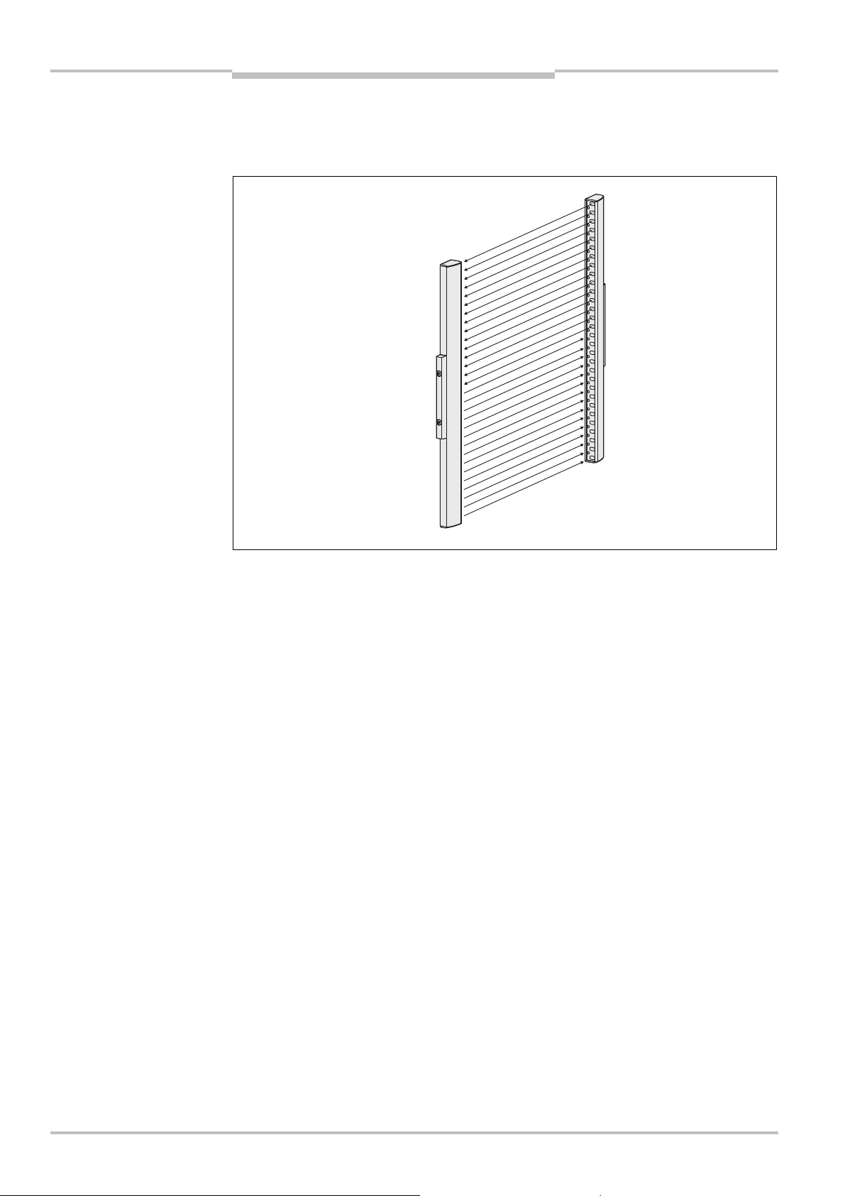
The miniTwin2 safety light curtain comprises two identical Twin Sticks of small size. Each
Twin Stick contains both a sender unit and a receiver unit (Fig. 1). The two Twin Sticks are
mounted such that sender unit and receiver unit are opposite each other. The housing
shape makes mounting intuitive.
12 © SICK AG • Industrial Safety Systems • Germany • All rights reserved 8013482/YT85/2016-02-23
Subject to change without notice
Page 13
Operating Instructions Chapter 3
Fig.2:
Operating principle
E.g. reset button
Protective field width
OSSD1
OSSD2
Receiver
Sender
Receiver
Sender
Protective field height
E.g. EDM
miniTwin2
Product description
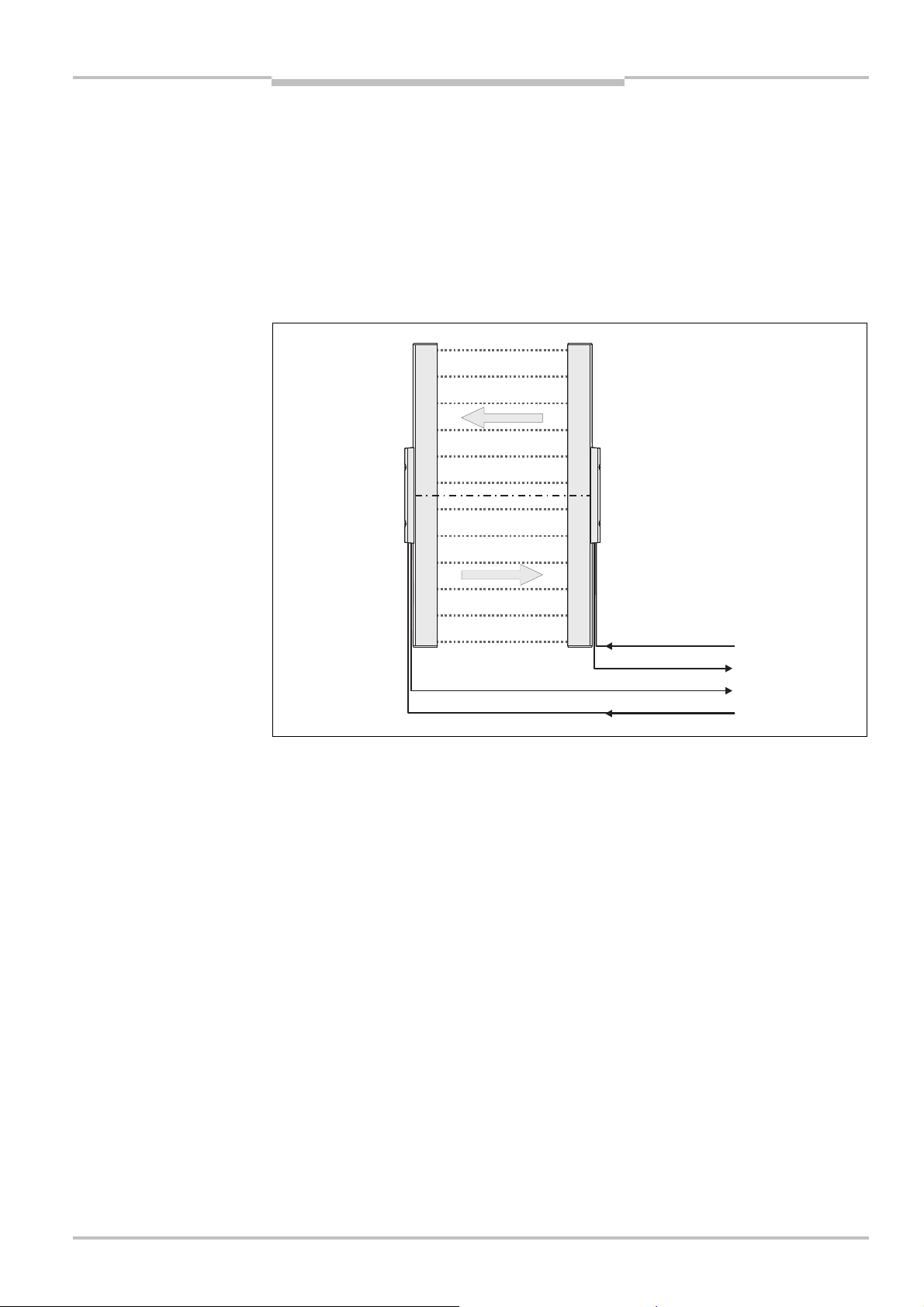
3.2.2 Operating principle safety light curtain
Between these two Twin Sticks is the protective field, defined by the protective field height
and the protective field width.
The construction size determines the protective field height of the appropriate system. For
the exact protective field height, please see Fig. 47 in section 9.3 “Dimensional drawings”
on page 68.
The protective field width is derived from the dimension of the light path between the Twin
Sticks and must not exceed the maximum permissible protective field width (see chapter 9
“Technical specifications” on page 64).
miniTwin2 safety light curtain
The two Twin Sticks automatically synchronise themselves optically. Each Twin Stick has
an OSSD and a so-called multifunction connection. The OSSDs are integrated into the
machine controller. It is possible to connect either a reset button or external device
monitoring (EDM) to the multifunction connections.
Prerequisites for the protective function of the miniTwin2 safety light curtain
The miniTwin2 safety light curtain operates correctly as a protective device only if the
following conditions are met:
The control of the machine must be electrical.
It must be possible to achieve a safe state on the machine at any time.
The miniTwin2 safety light curtain must be mounted in such a way that objects
penetrating into the hazardous area are safely identified.
The reset button must be fitted outside the hazardous area such that it cannot be
operated by a person working inside the hazardous area. When operating the reset
button, the operator must have full visual command of the hazardous area.
The statutory and local rules and regulations must be observed when installing and
using the device.
8013482/YT85/2016-02-23 © SICK AG • Industrial Safety Systems • Germany • All rights reserved 13
Subject to change without notice
Page 14
Chapter 3 Operating Instructions
Fig.3:Cascading of the
Guest
2
Guest
1
Host
miniTwin2
miniTwin2 safety light curtain
Product description
3.2.3 Cascading
To provide effective presence detection a maximum of three miniTwin2 can be connected
in series as “cascade”.
The device connected to the control cabinet is the main sensor, called host. The subsequent sensors are called guest 1 and guest 2. On the host you can configure the Reset
and EDM functions.
WARNING
The miniTwin2 can be connected together as required and form, without configuration, a
functional cascaded system. After disconnecting cascaded systems to form individual
systems, the individual miniTwin2 can also be used as a standalone devices without
configuration.
Whether a device is used as a cascaded device or as a standalone device is defined by the
connection plug.
Check the effectiveness of the protective device after any change to a system using
the test rod!
Check the effectiveness of the protective device as described in section 6.7 “Test notes”
on page 56.
Benefits of cascading
no additional external circuitry required, quick to connect
resolution and protective field height may differ among the individual systems
Limits of cascading
The maximum protective field width must be guaranteed for each individual system!
The maximum cable length between two cascaded systems must not exceed 3 metres.
You must maintain a minimum distance between the protective fields on the miniTwin2
host and miniTwin2 guest 2 (see section 4.1.3 “Minimum distance for cascaded
systems” on page 26).
14 © SICK AG • Industrial Safety Systems • Germany • All rights reserved 8013482/YT85/2016-02-23
Subject to change without notice
Page 15
Operating Instructions Chapter 3
Fig.4:
Hazardous point
Fig.6:
Access protection
miniTwin2
Product description
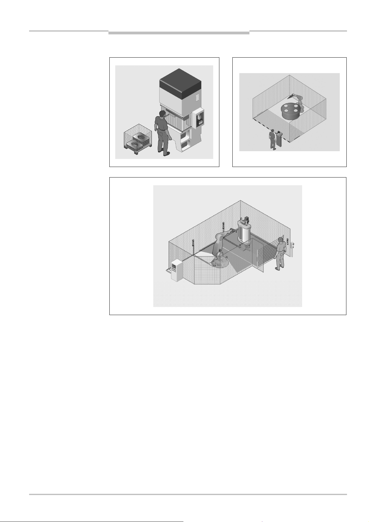
3.3 Application examples
protection using a miniTwin2
safety light curtain
(left)
Fig. 5: Hazardous area
protection using a miniTwin2
safety light curtain
(right)
using a miniTwin2 safety light
curtain
8013482/YT85/2016-02-23 © SICK AG • Industrial Safety Systems • Germany • All rights reserved 15
Subject to change without notice
Page 16
Chapter 3 Operating Instructions
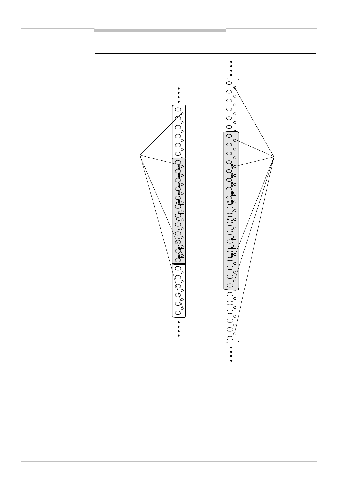
Fig.7:
Status indicators on
Bi-colour LEDs
120mm240mm180mm300mmBi-colour LEDs
miniTwin2
Product description
3.4 Status indicators
the miniTwin2
Green/red
Green/red
16 © SICK AG • Industrial Safety Systems • Germany • All rights reserved 8013482/YT85/2016-02-23
Notes
Illuminated LEDs indicate the status of the miniTwin2 safety light curtain. Flashing LEDs
prompt you to take an action.
Fig. 7 shows the two smallest protective field heights 120 and 180 mm. In the case of
safety light curtains with larger protective fields (240 mm, 300 mm etc.) the LED
displays are always in the middle of the protective field. These miniTwin2 have further
bi-colour LEDs that are fitted every 60 mm above and below the status indicators.
Subject to change without notice
Page 17

Operating Instructions Chapter 3
Tab.2:
Meaning of the status
miniTwin2
Product description
indicators
LED Display Comment
OUT Green/red
Bi-colour LED illuminates green, if protective field un-
occupied (OSSD on)
Bi-colour LED illuminates red, if protective field infringed
(OSSDs off)
Orange External device monitoring configured EDM
Orange For the configuration of EDM on the first OSSD status
change, the safety light curtain expects a change from
4 V to 0 V on the multifunction input.
2
Or:
In connection with the ERR LED Red: External device
monitoring signalling faulty contactor
White External communication active (e.g. for service) COM
White No optical communication to another Twin Stick
Or:
Feedback on the deactivation of the configuration
Orange Reset configured RES
Orange Reset required
Or:
In connection with the ERR LED Red and the EDM
LED Orange: Error in the configuration or the cabling.
Please refer to chapter 8 on page 62.
Red Protective field infringed ERR
1, 2, 3, 4, 5
Red Error. Please refer to chapter 8 on page 62.
Blue Indication of the quality of the alignment. Please refer to
section 6.2 on page 53.
Blue In connection with the ERR LED Red: Display of an
error. Please refer to chapter 8 on page 62.
Or:
Feedback on the deactivation of the configuration
8013482/YT85/2016-02-23 © SICK AG • Industrial Safety Systems • Germany • All rights reserved 17
Subject to change without notice
Page 18
Chapter 3 Operating Instructions
Fig.8:
Configurable functions
K1K2k1k2Reset button
OSSD1
OSSD2
EDM24V DC0V
DC
miniTwin2
Product description
3.5 Configurable functions
his section describes the functions of the miniTwin2 safety light curtain that can be
T
configured.
Test the protective device after any changes!
ARNING
W
Changes to the configuration of the devices can degrade the protective function. After
every change to the configuration you must therefore check the effectiveness of the
protective device (see section 6.7 “Test notes” on page 56).
The person who makes the change is also responsible for the correct protective function of
the device.
Reset and external device monitoring can be configured on the miniTwin2 safety light
curtain.
18 © SICK AG • Industrial Safety Systems • Germany • All rights reserved 8013482/YT85/2016-02-23
Reset is configured by activating the reset button with a specific cycle (see section 6.5
“Configuration of the Reset function” on page 55).
If the input is wired correctly to the contactors, the external device monitoring (EDM) is
configured automatically the first time the OSSDs are switched (see sections 5.5
“External device monitoring (EDM)” on page 49 and 6.6 “Configuration of the external
device monitoring (EDM)” on page 56).
Subject to change without notice
Page 19
Operating Instructions Chapter 3
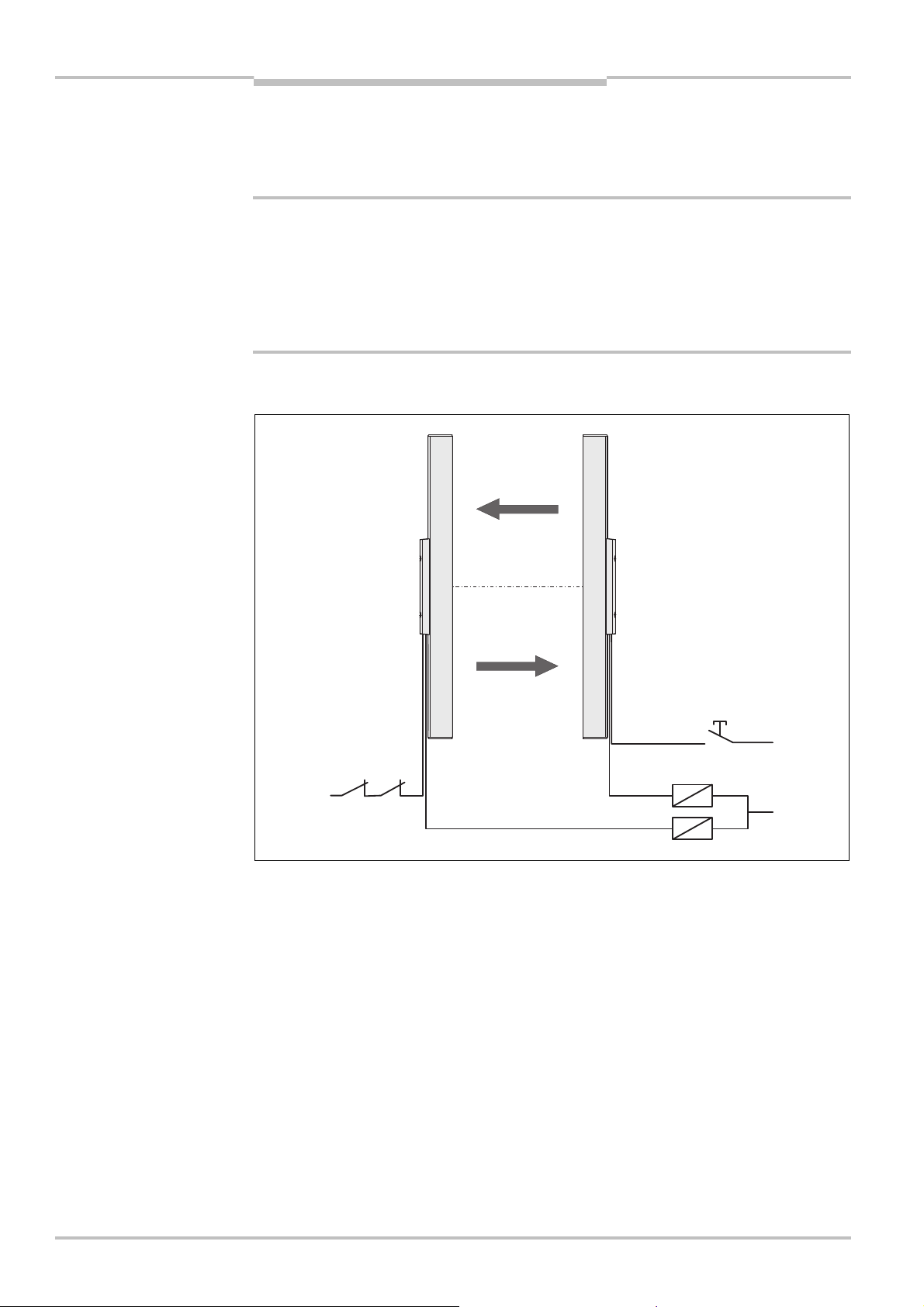
Fig.9:
Outline drawing of the
miniTwin2
protective operation
Note
Product description
3.5.1 Reset
The dangerous state of the machine () is interrupted if the light path is broken (), and
is not re-enabled ( ) until the operator presses the reset button.
Do not confuse reset and the restart interlock with the starting interlock on the machine.
The starting interlock prevents the machine starting after switching on. Reset and the
restart interlock prevent the machine starting again after an error or an interruption of the
light path.
You can only implement a restart interlock via an external machine restart interlock:
The miniTwin2 has no control over the restart.
You can implement a reset using the Reset function on the miniTwin2:
The miniTwin2 controls the machine start.
WARNING
Ensure on the usage of the Reset function that an erroneous start-up cannot result in a
dangerous situation!
8013482/YT85/2016-02-23 © SICK AG • Industrial Safety Systems • Germany • All rights reserved 19
Subject to change without notice
Page 20

Chapter 3 Operating Instructions
Tab.3:
Permissible
miniTwin2
Product description
The possible combinations of reset and restart interlock are shown in the following table:
configuration of the restart
interlock
WARNING
Reset function of
the miniTwin2
Deactivated Deactivated Only if the safety light curtain cannot be stood
Deactivated Activated All
Activated Deactivated Only if the safety light curtain cannot be stood
Activated Activated All (see “Reset and restart interlock on the
It is imperative you configure the application with restart interlock if it is possible to
stand behind the safety light curtain!
The miniTwin2 is unable to verify if the restart interlock of the machine is operable. If in
applications in which it is possible to stand behind the safety light curtain you deactivate
both the internal Reset function and the external restart interlock, you will place the
machine operator in acute danger.
Restart interlock of
the machine
Permissible
application
behind. Observe EN 60204A1!
behind. Observe EN 60204A1!
Note: It must be ensured that with the power
supply to the machine switched on, access to
the hazardous area is only possible via the
active protective field on the safety light
curtain.
If this condition is not met, e.g. during main-
tenance work on the machine with a side
cover open, it is imperative the supply of
power to the machine is interrupted!
machine” further below).
Notes
Recommendation
The electrical connection of the reset button is described in section 5.4 “Reset button”
on page 48.
Section 6.5 “Configuration of the Reset function” on page 55 describes how to con-
figure the function.
Reset and restart interlock on the machine
If you activate reset on the miniTwin2 and implement a restart interlock on the machine,
then reset and restart interlock each have a dedicated button.
After actuation of the reset button …
the miniTwin2 activates the output signal switching devices.
the safety light curtain switches to green.
Only the external restart interlock prevents the machine from restarting. After pressing the
reset button for the miniTwin2, the operator must also press the restart button for the
machine. If the reset button and the restart button are not pressed in the specified
sequence, the dangerous state remains disrupted.
The reset button prevents the accidental and inadvertent operation of the external restart
button. The operator must first acknowledge the safe state with the reset button.
20 © SICK AG • Industrial Safety Systems • Germany • All rights reserved 8013482/YT85/2016-02-23
Subject to change without notice
Page 21

Operating Instructions Chapter 3
miniTwin2
Product description
3.5.2 External device monitoring (EDM)
The EDM checks if the contactors actually de-energize when the protective device
responds. If you activate external device monitoring, then the miniTwin2 checks the
ontactors after each interruption to the light path and prior to the machine restart. The
c
EDM can so identify if one of the contactors has welded, for instance. In this case the
external device monitoring places the system in a safe operational state. The OSSDs are
ot re-activated in this case.
n
Notes
The electrical connection for the external device monitoring is described in section 5.5
“External device monitoring (EDM)” on page 49.
Section 6.6 “Configuration of the external device monitoring (EDM)” on page 56
describes how to configure the function.
8013482/YT85/2016-02-23 © SICK AG • Industrial Safety Systems • Germany • All rights reserved 21
Subject to change without notice
Page 22

Chapter 4 Operating Instructions
miniTwin2
Mounting
4 Mounting
his chapter describes the preparation and completion of the mounting of the miniTwin2
T
safety light curtain. The mounting requires two steps:
determining the necessary minimum distance
mounting using the available brackets (see section “Safety light curtains” in the SICK
product catalogue “Industrial Safety Systems” or www.sick.com)
The following steps are necessary after mounting:
completing the electrical connections (chapter 5)
alignment of the miniTwin2 safety light curtain (section 6.2)
testing the installation (section 6.7)
4.1 Determining the minimum distance
The safety light curtain must be mounted with sufficient minimum distance:
from the hazardous point
from reflective surfaces
WARNING
No protective function without sufficient minimum distance!
The reliable protective effect of the safety light curtain depends on the system being
mounted with the correct minimum distance from the hazardous point.
4.1.1 Minimum distance from the hazardous point
A minimum distance must be maintained between the safety light curtain and the
hazardous point. This ensures that the hazardous point can only be reached after the
dangerous state of the machine has been completely stopped.
The minimum distance as per EN ISO 13855 and EN ISO 13857 depends on:
stopping/run-down time of the machine or system
(the stopping/run-down time is shown in the machine documentation or must be
determined by taking a measurement.)
response time of the entire protective device, e.g. miniTwin2 consisting of host and
guest (response times see 9.1 “Data sheet” on page 64)
reach or approach speed
resolution of the safety light curtain and/or beam separation
other parameters that are stipulated by the standard depending on the application
22 © SICK AG • Industrial Safety Systems • Germany • All rights reserved 8013482/YT85/2016-02-23
Subject to change without notice
Page 23
Operating Instructions Chapter 4
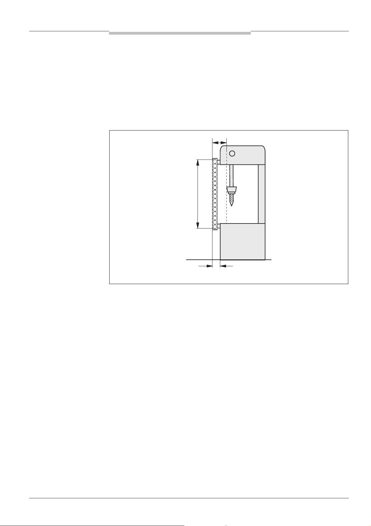
Fig.10:
Minimum distance
Hazardous
Distance to avoid standing behind
75
mm
Minimum distance S (D
)
Protective field height
miniTwin2
Mounting
Under the authority of OSHA and ANSI the minimum distance as specified by
ANSI B11.19:2003C04, Annex D and Code of Federal Regulations, Volume 29,
Part 1910.217 … (h) (9) (v) depends on:
stopping/run-down time of the machine or system (the stopping/run-down time is shown
in the machine documentation or must be determined by taking a measurement.)
response time of the entire protective device, e.g. miniTwin2 consisting of host and
guest (response times see 9.1 “Data sheet” on page 64)
reach or approach speed
other parameters that are stipulated by the standard depending on the application
from the hazardous point
Note
s
point
How to calculate the minimum distance S according to EN ISO 13855 and
EN ISO 13857:
The following calculation shows an example calculation of the minimum distance.
Depending on the application and the ambient conditions, a different calculation may be
necessary.
First, calculate S using the following formula:
S = 2000 × T + 8 × (d – 14) [mm]
Where …
T = Stopping/run-down time of the machine
+ Response time of the protective device after light path interruption [s]
d = Resolution of the safety light curtain [mm]
S = Minimum distance [mm]
The reach/approach speed is already included in the formula.
If the result S is 500 mm, then use the determined value as the minimum distance.
If the result S is > 500 mm, then recalculate S as follows:
S = 1600 × T + 8 × (d – 14) [mm]
If the new value S is > 500 mm, then use the newly determined value as the minimum
distance.
If the new value S is 500 mm, then use 500 mm as the minimum distance.
8013482/YT85/2016-02-23 © SICK AG • Industrial Safety Systems • Germany • All rights reserved 23
Subject to change without notice
Page 24

Chapter 4 Operating Instructions
miniTwin2
Mounting
Example:
Stopping/run-down time of the machine = 290 ms
esponse time after light path interruption = 30 ms
R
Resolution of the safety light curtain = 14 mm
T = 290 ms + 30 ms = 320 ms = 0.32 s
S = 2000 × 0.32 + 8 × (14 – 14) = 640 mm
S > 500 mm, for this reason:
S = 1600 × 0.32 + 8 × (14 – 14) = 512 mm
How to calculate the minimum distance Dsaccording to ANSI B11.19:2003C04,
Annex D and Code of Federal Regulations, Volume 29, Part 1910.217 … (h) (9) (v):
Note
The following calculation shows an example calculation of the minimum distance.
Depending on the application and the ambient conditions, a different calculation may be
necessary.
Calculate D
= Hs× (Ts+ Tc+ Tr+ T
D
s
using the following formula:
s
) + D
m
b
f
p
Where …
D
= The minimum distance in inches (or millimetres) from the hazardous point to the
s
protective device
= A parameter in inches/second or millimetres/second, derived from data on
H
s
approach speeds of the body or parts of the body. Often 63 inches/second
(1600 mm/second) is used for H
T
= Stopping/run down time of the machine tool measured after the final control
s
.
s
element
= Response time of the control system
T
c
T
= Response time of the entire protective device after light path interruption
r
T
= Additional time to compensate for the lack of brake wear monitoring
bm
Note
Any additional response times must be accounted for in this calculation.
= An additional distance added to the overall minimum distance required. This
D
pf
value is based on intrusion toward the hazardous point prior to actuation of the
electro-sensitive protective equipment (ESPE). Values range from 0.25 inches to
48 inches (6 to 1220 millimetres) or more depending on application.
Example:
For perpendicular protection using an opto-electronic protective device with an
object sensitivity (effective resolution) less than 2.5 inches (64 millimetres), D
pf
can be approximated based on the following formula:
(inches) = 3.4 × (effective resolution – 0.276), but not less than 0.
D
pf
24 © SICK AG • Industrial Safety Systems • Germany • All rights reserved 8013482/YT85/2016-02-23
Subject to change without notice
Page 25
Operating Instructions Chapter 4
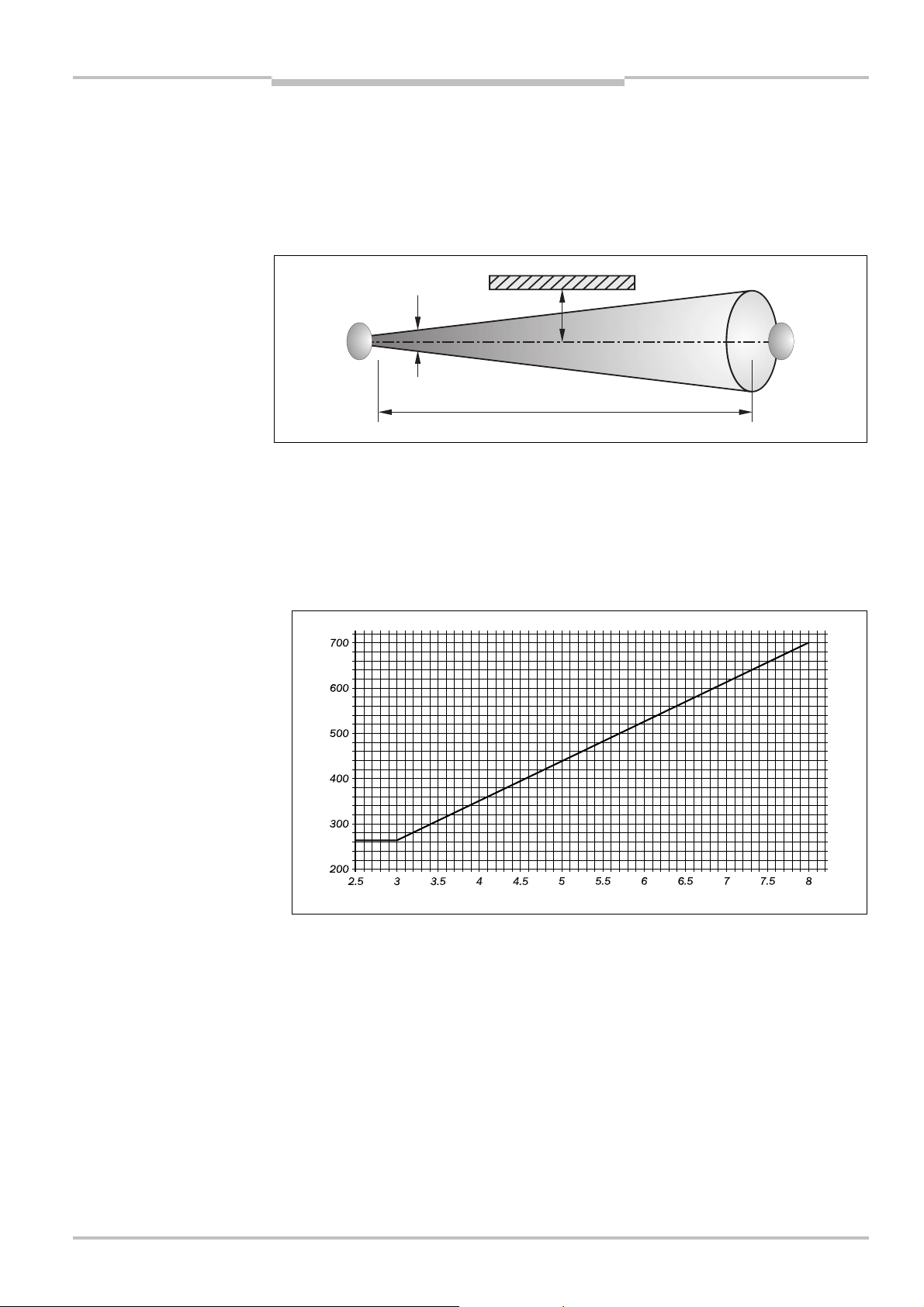
Fig.11:
Minimum distance to
Fig.12:
Graph, minimum
Reflective surface
Minimum distance a
Distance
D
Field of view
Distance D [m]
Minimum distance a [mm]
miniTwin2
Mounting
4.1.2 Minimum distance to reflective surfaces
The light beams from the safety light curtain may be deflected by reflective surfaces. This
can result in failure to identify an object.
All reflective surfaces and objects (e.g. material bins) must therefore be located at a
minimum distance a from the protective field of the system. The minimum distance a
depends on the distance D between the Twin Sticks.
reflective surfaces
distance from reflective
surfaces
Note
The field of view of the sender and receiver optics is identical.
How to determine the minimum distance from reflective surfaces:
Determine the distance D [m] between the Twin Sticks.
Up to a protective field width of 3 m, the minimum distance is at least 262 mm.
For a protective field width of more than 3 m, read the minimum distance a [mm] from
the graph:
8013482/YT85/2016-02-23 © SICK AG • Industrial Safety Systems • Germany • All rights reserved 25
Subject to change without notice
Or:
Calculate the minimum distance for a protective field width of more than 3 m using the
formula
a [mm] = tan 5° × D [m] × 1000
Example:
a = tan 5° × 4 m × 1000
a = 349.95 mm ~ 350 mm
Page 26
Chapter 4 Operating Instructions
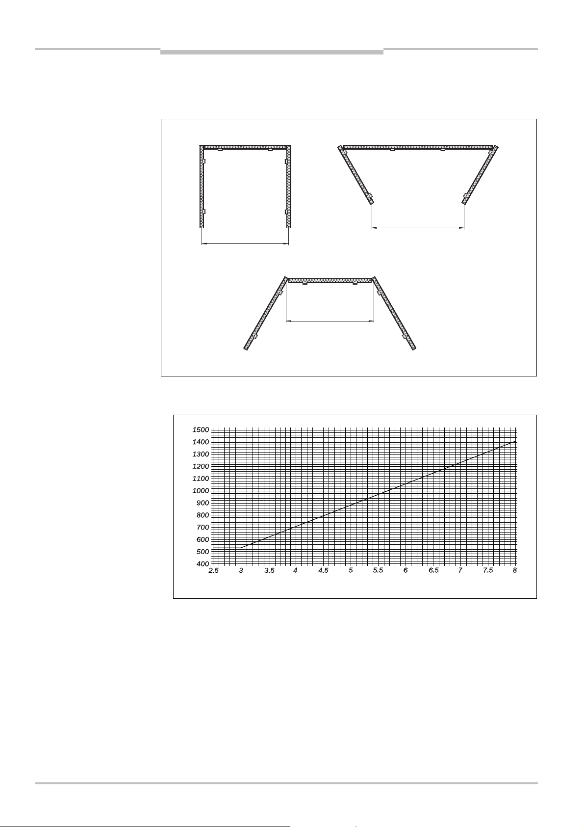
Fig.13:
Minimum distance
Fig.14:
Diagram minimum
a min.
529
Guest
1
Guest
1
Host
Host
Host
Guest2Guest
2
Guest
2
a min.
529
Guest
1
a min.
529
Distance D [m]
Minimum distance a [mm]
miniTwin2
Mounting
4.1.3 Minimum distance for cascaded systems
In a cascaded system with a protective field width of up to 3 m you must maintain a
minimum distance of 529 mm between the host and guest 2 during mounting.
between host and guest 2
(mm)
For a protective field width of more than 3 m, read the minimum distance a [mm] from
the graph:
distance between host and
guest 2
Or:
Calculate the minimum distance for a protective field width of more than 3 m using the
formula
a [mm] = tan 10° × D [m] × 1000
Example:
a = tan 10° × 4 m × 1000
a = 705.31 mm ~ 706 mm
26 © SICK AG • Industrial Safety Systems • Germany • All rights reserved 8013482/YT85/2016-02-23
Subject to change without notice
Page 27

Operating Instructions Chapter 4
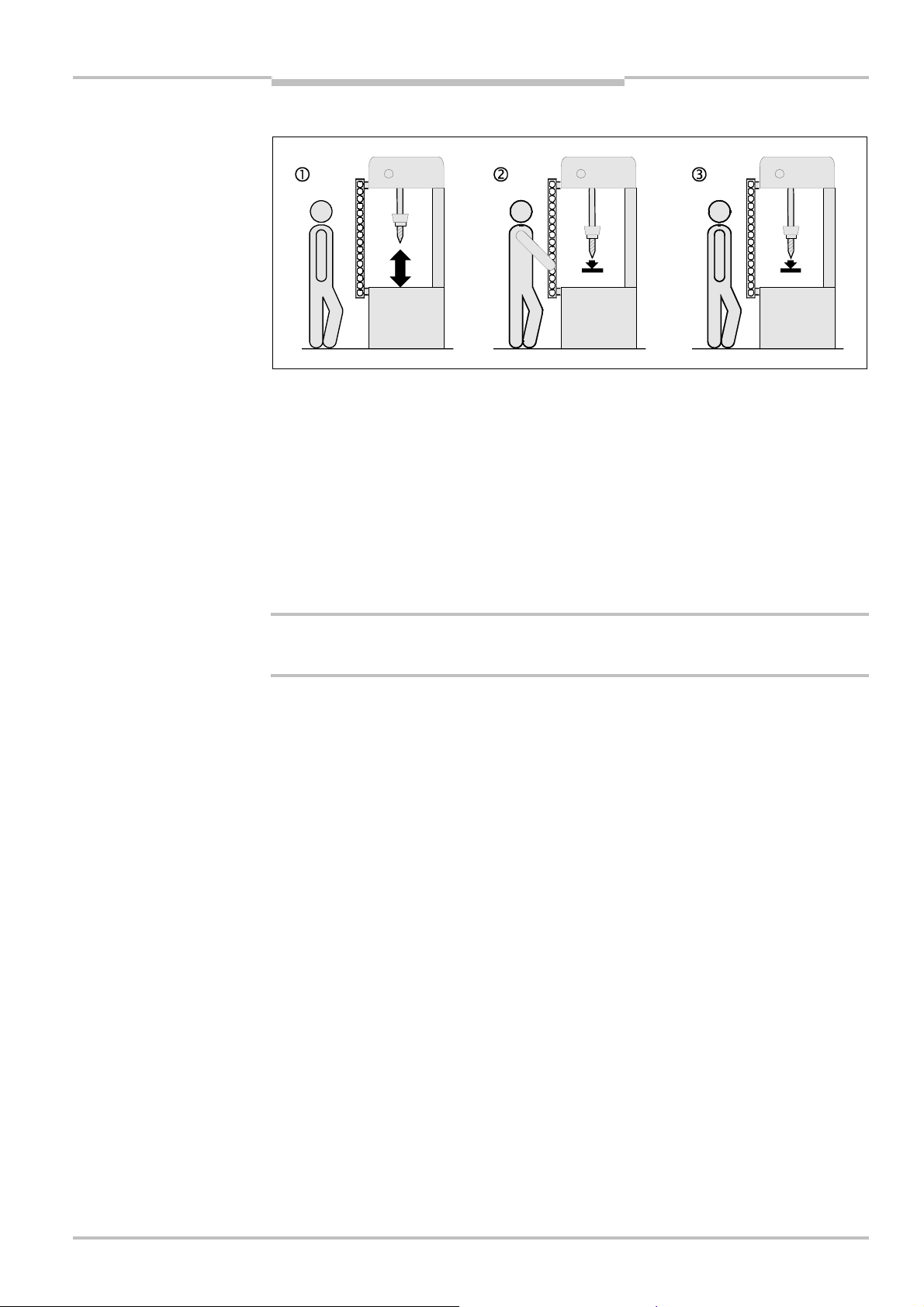
Fig.15:
The correct mounting
miniTwin2
Mounting
4.2 Steps for mounting the device
pecial features to note during mounting:
S
WARNING
(above) must eliminate the
errors (below) standing
behind, reaching under and
reaching over
Always mount the Twin Sticks on a flat surface.
During mounting, ensure that the safety light curtain is aligned correctly. The two
housings for the Twin Sticks must be exactly opposite each other.
Take suitable measures to attenuate vibration if the shock requirements are above the
values given in section 9.1 “Data sheet” on page 64.
Observe the minimum distance of the system during mounting. On this subject read the
section 4.1 “Determining the minimum distance” on page 22.
Mount the safety light curtain such that reaching under, reaching over or standing
behind the safety light curtain is not possible and that the safety light curtain cannot be
displaced.
8013482/YT85/2016-02-23 © SICK AG • Industrial Safety Systems • Germany • All rights reserved 27
Subject to change without notice
Once the system is mounted, one or several of the enclosed self-adhesive safety
information labels must be affixed:
– Use only information labels which the operators of the machine can understand.
– Affix the information labels such that they are easily visible by the operators during
operation. After attaching additional objects and equipment, the information labels
must not be concealed from view.
– Affix the information label “Important Information” to the system in close proximity to
the miniTwin2.
Page 28

Chapter 4 Operating Instructions
Fig.16:
Mounting direction of
Tab.4:
Mounting possibilities
Twin-Stick
Twin-Stick
miniTwin2
Mounting
4.2.1 Mounting direction of the Twin Sticks
the Twin Sticks
Sender
Receiver
Receiver
Sender
Note
The miniTwin2 safety light curtain comprises two identical Twin Sticks of small size. Each
Twin Stick contains both a sender unit and a receiver unit (Fig. 1). The two Twin Sticks are
mounted such that sender unit and receiver unit are opposite each other. The housing
shape makes mounting intuitive.
After the electrical installation, you can check the quality of the alignment of the safety
light curtain (see section 6.2 on page 53). Please ensure even during mounting that the
Twin Sticks are aligned.
4.2.2 Mounting possibilities
The miniTwin2 can be fastened in the following ways:
Bracket Protective field
height
O-Fix V 180 mm Fixed mounting position
Application characteristics Page
29
Flush
Not suitable for cascading.
C-Fix V 180 mm Flexible mounting position 31
L-Fix W 540 mm Fixed mounting position
33
Not suitable for cascading.
28 © SICK AG • Industrial Safety Systems • Germany • All rights reserved 8013482/YT85/2016-02-23
Combination
CAFix/L-Fix
V 240 mm Fixed mounting position of the
LAFix bracket
Flexible mounting position of the
CAFix bracket
C-Fix-Flex V 180 mm Flexible mounting position
Flexible alignment of the protective
field
Refer on the internet to www.sick.com for additional information.
35
37
Subject to change without notice
Page 29

Operating Instructions Chapter 4
Fig.17:
Application example
Fig.18:
O@Fix bracket
Part No. 2045835
DIN
125 washer
Fixing screw M5
miniTwin2
Mounting
4.2.3 Mounting with OCFix bracket
Using the OAFix bracket you can mount the safety light curtain flat, e.g. directly on the
machine base.
for mounting with O@Fix
bracket
The OAFix bracket is mounted at the top and bottom of the miniTwin2 safety light curtain.
The length of the related Twin Stick is increased by ca. 13 mm by the OAFix bracket (see
dimensional drawing in section 9.3.2 on page 69).
8013482/YT85/2016-02-23 © SICK AG • Industrial Safety Systems • Germany • All rights reserved 29
Subject to change without notice
How to mount the miniTwin2 using OCFix brackets:
First mount the two OAFix brackets in the correct positions, however do not tighten the
fixing screws yet.
Insert the Twin Stick between the two OAFix brackets. In applications in which high
vibration may occur, bond the Twin Stick to the mounting surface in the middle of the
device using double-sided adhesive tape from a device length of 600 mm (see in
Fig. 19 on page 30).
Then fasten the screws of the OAFix bracket to a torque of 5 Nm. Higher torques can
damage the brackets; lower torques provide inadequate protection against
displacement.
Page 30

Chapter 4 Operating Instructions
Fig.19:
Mounting of the
Tab.5:
Hole distance for
L
miniTwin2
miniTwin2 with O@Fix bracket
Mounting
mounting with O@Fix bracket
Construction size of the Twin Stick [mm] Hole distance L [mm]
120 132.6
180 192.6
240 252.6
300 312.6
360 372.6
420 432.6
480 492.6
540 552.6
600 612.6
660 672.6
720 732.6
780 792.6
840 852.6
900 912.6
960 972.6
1020 1032.6
1080 1092.6
1140 1152.6
30 © SICK AG • Industrial Safety Systems • Germany • All rights reserved 8013482/YT85/2016-02-23
1200 1212.6
Subject to change without notice
Page 31

Operating Instructions Chapter 4
Fig.20:
Application example
Fig.21:
C@Fix bracket
Part No. 2045843
Washer
Fixing screw M5
miniTwin2
Mounting
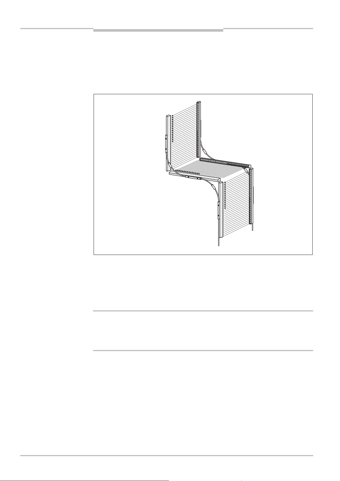
4.2.4 Mounting with CCFix bracket
The CAFix bracket can be positioned very flexibly on the Twin Stick. It does not increase the
length of the miniTwin2 safety light curtain.
Using the C-Fix bracket, Twin Sticks can be mounted with a butt joint or at right angles to
each other without a reduction in the resolution at the butt joints.
for mounting with C@Fix
bracket
8013482/YT85/2016-02-23 © SICK AG • Industrial Safety Systems • Germany • All rights reserved 31
Subject to change without notice
Page 32

Chapter 4 Operating Instructions
Fig.22:
Mounting of the
¼L¼L½L
miniTwin2
Mounting
How to mount the miniTwin2 with CCFix brackets:
Note
The CAFix bracket can not be used on a device with a protective field height of 120 mm.
Mount the CAFix brackets () such that the Twin Stick is positioned at the correct
height.
Recommendation
In applications in which juddering and vibration can occur as well as for sizes V 360 mm
we recommend mounting the brackets a distance of one quarter of the length of the
Twin Stick from the end of the Twin Stick.
Fasten the M5 screws to a torque approx. 3 Nm. Higher torques can damage the
brackets; lower torques provide inadequate protection against displacement.
miniTwin2 with C@Fix brackets
Fit the Twin Stick in the CAFix brackets and press it down gently ().
Rotate the Twin Stick to the rear until it engages in the CAFix brackets ().
Move the Twin Stick to the required position.
Fasten the M3 screws for the CAFix brackets to a torque of approx. 1.5 Nm to fix the
Twin Stick ().
32 © SICK AG • Industrial Safety Systems • Germany • All rights reserved 8013482/YT85/2016-02-23
Subject to change without notice
Page 33

Operating Instructions Chapter 4
Fig.23:
L@Fix bracket
Part No. 2045843
Washers
1. Fixing screw M5
2. Fixing screw M5 (optional)
miniTwin2
Mounting
4.2.5 Mounting with LCFix bracket
Mount the 120 mm miniTwin2 with the aid of two LA Fix brackets.
Mounting with two LAFix brackets is only allowed up to a size of 540 mm.
ote
N
Note
Fasten the screws of the LAFix bracket to a torque of approx. 3 Nm. Higher torques can
damage the bracket; lower torques provide inadequate protection against vibration.
8013482/YT85/2016-02-23 © SICK AG • Industrial Safety Systems • Germany • All rights reserved 33
Subject to change without notice
Page 34

Chapter 4 Operating Instructions
Fig.24:
Mounting of the
miniTwin2
Mounting
How to mount the LCFix bracket:
Mount the bottom LAFix bracket () with end piece () fitted on the mounting surface
uch that the Twin-Stick is at the correct height.
s
Mount the mounting plate () for the top LAFix bracket such that the Twin Stick
protrudes at the top by up to 1 mm.
Recommendation
From a size of 420 mm use two fixing screws per mounting plate, to obtain increased
protection against twisting of the LAFix bracket.
Fit the end piece () for the LAFix bracket to the top end cap on the Twin Stick.
Fasten the screws for the LAFix bracket () to a torque of approx. 1.5 Nm, to obtain an
adequate bracket clamping force.
miniTwin2 with L@Fix bracket
34 © SICK AG • Industrial Safety Systems • Germany • All rights reserved 8013482/YT85/2016-02-23
Subject to change without notice
Page 35

Operating Instructions Chapter 4
Fig.25:
Application exampl
e
Fig.26:
L@Fix bracket
Part No. 2045843
Washers
1. Fixing screw M5
2. Fixing scr
ew M5
miniTwin2
Mounting
4.2.6 Mounting with CCFix bracket and LCFix bracket
The CAFix bracket can be combined with the LAFix bracket. Then both the position of the
safety light curtain is fixed and the flexible mounting of a CAFix bracket is provided.
Recommendation
In applications in which juddering and vibration can occur as well as for sizes V 360 mm
we recommend mounting the brackets a distance of one quarter of the length of the
Twin Stick from the end of the Twin Stick.
for mounting with C@Fix and
L@Fix bracket
8013482/YT85/2016-02-23 © SICK AG • Industrial Safety Systems • Germany • All rights reserved 35
Subject to change without notice
Page 36

Chapter 4 Operating Instructions
Fig.27:
Mounting of the
¼L
¾L
miniTwin2
Mounting
How to mount the miniTwin2 using CCFix brackets and LCFix brackets:
Mount the LAFix bracket such that the Twin Stick is positioned at the correct height.
Lightly tighten the first of the two fixing screws M5 ().
Ensure the LAFix bracket is initially only lightly fixed and does not twist.
Now tighten the second of the two fixing screws M5 (), also lightly.
Now alternately fasten the two screws to a torque of approx. 3 Nm. Higher torques can
damage the bracket; lower torques provide inadequate protection against vibration.
miniTwin2 with C@Fix bracket
and L@Fix bracket
36 © SICK AG • Industrial Safety Systems • Germany • All rights reserved 8013482/YT85/2016-02-23
Recommendation
Mount the CAFix bracket () on the other end of the Twin Stick.
From devices with a size of 360 mm we recommend mounting an additional CAFix
bracket near the LAFix bracket in case of high transverse forces on the housing.
Fit the Twin Stick in the CAFix bracket and press it down gently ().
Rotate the Twin Stick to the rear until it engages in the CAFix bracket ().
Move the Twin Stick down until it is seated correctly in the LAFix bracket ().
Fasten the M3 screws of the LAFix bracket () to a torque of approx. 1,5 Nm.
Fasten the M3 screws for the CAFix bracket to a torque of approx. 1.5 Nm to fix the
Twin Stick ().
Subject to change without notice
Page 37

Operating Instructions Chapter 4
Fig.28:C-
Fix-Flex bracket
Part No. 2056598
Fix
ing screw
miniTwin2
Mounting
4.2.7 Mounting with CCFix-Flex bracket
The C-Fix-Flex bracket can be positioned very flexibly on the Twin Stick. It does not increase
the length of the safety light curtain miniTwin2.
Using the C-Fix-Flex bracket, Twin Sticks can be mounted with a butt joint or at right angles
to each other without a reduction in the resolution at the butt joints.
Using the C-Fix-Flex bracket the Twin Sticks can be mounted such that the protective field
is either parallel or perpendicular to the mounting surface. The C-Fix-Flex bracket makes it
ossible to correct the mounting angle by ±4°.
p
M5× 16
Note
Recommendation
How to mount the miniTwin2 using C-Fix-Flex brackets:
The C-Fix-Flex bracket can not be used on a device with a protective field height of
120 mm.
First mount the C-Fix-Flex brackets () hand-tight and such that the Twin Stick is
positioned at the correct height.
In applications in which juddering and vibration can occur as well as for sizes V 360 mm
we recommend mounting the brackets a distance of one quarter of the length of the
Twin Stick from the end of the Twin Stick.
Insert the Twin Stick in the C-Fix-Flex brackets and push it to the rear until it engages
().
Move the Twin Stick to the required position.
Fasten the M3 screws for both C-Fix-Flex brackets to a torque of approx. 1.5 Nm to fix
the Twin Stick ().
Correct the angle of the bracket for optimal alignment ().
Fasten the M5 fixing screws of both C-Fix-Flex brackets to a torque of approx. 5 Nm.
Higher torques can damage the bracket; lower torques provide inadequate protection
against vibration ().
8013482/YT85/2016-02-23 © SICK AG • Industrial Safety Systems • Germany • All rights reserved 37
Subject to change without notice
Page 38

Chapter 4 Operating Instructions
Fig.29:
Mounting using
20.64°3 mm
Across flats
miniTwin2
C@Fix@Flex bracket, protective
field parallel to the mounting
surface
Mounting
38 © SICK AG • Industrial Safety Systems • Germany • All rights reserved 8013482/YT85/2016-02-23
Subject to change without notice
Page 39

Operating Instructions Chapter 4
Fig.30:
Mounting using
20.4
4°
4°
Min. 29
Min. 40
3 mm
Across flats
miniTwin2
C@Fix@Flex bracket, protective
field perpendicular to the
mounting surface
Mounting
8013482/YT85/2016-02-23 © SICK AG • Industrial Safety Systems • Germany • All rights reserved 39
Subject to change without notice
Page 40

Chapter 4 Operating Instructions
Fig.31:
Resolution between
71420401326C-Fix bracket/
O-Fix bracket
L-Fix bracket
miniTwin2
Mounting
4.3 Resolution at the end of the Twin Sticks
f you mount several safety light curtains with butt joints or mount a safety light curtain on
I
a wall, then the resolution will vary at the butt joints or the ends of the Twin Sticks
depending on the type of bracket. Fig. 31 shows:
The resolution between two Twin Sticks (higher value).
The resolution for a butt joint between a Twin Stick and a wall or the floor (lower value).
Twin Sticks mounted with a
butt joint or with a wallmounted Twin Stick (mm)
Example: Twin-Sticks with
14 mm resolution
C-Fix-Flex bracket
40 © SICK AG • Industrial Safety Systems • Germany • All rights reserved 8013482/YT85/2016-02-23
Subject to change without notice
Page 41

Operating Instructions Chapter 5
miniTwin2
Electrical installation
5 Electrical installation
witch the entire machine/system off line!
S
WARNING
The machine/system could unintentionally start up while you are connecting the devices.
Ensure that the entire machine/system is disconnected during the electrical
nstallation.
i
Ensure that downstream contactors are monitored!
Downstream contactors must be positively guided and monitored (see section 5.5
“External device monitoring (EDM)” on page 49)!
Connect OSSD1 and OSSD2 separately!
You are not allowed to connect OSSD1 and OSSD2 together, otherwise signal safety will
not be ensured.
Ensure that the machine controller processes the two signals separately.
If you connect loads to the OSSDs that are not reverse polarity protected, then you must
connect the 0 V connections for these loads and the related protective device
separately, one after the other, to the same 0 V terminal strip. Only then is it ensured
that in the case of a fault, it is not possible for a potential difference to form between
the 0 V connections for the loads and the related protective device.
8013482/YT85/2016-02-23 © SICK AG • Industrial Safety Systems • Germany • All rights reserved 41
Subject to change without notice
Page 42

Chapter 5 Operating Instructions
miniTwin2
Electrical installation
Notes
The two outputs are protected against short-circuits to 24 V DC and 0 V. When the light
path is clear, the signal level on the outputs is HIGH DC (at potential), when the light
path is interrupted or there is a device fault the outputs are LOW DC.
The miniTwin2 safety light curtain meets the interference suppression requirements
(EMC) for industrial use (interference suppression class A). When used in residential
areas it can cause interference.
To ensure full electromagnetic compatibility (EMC), functional earth (FE) must be
connected.
To meet the requirements of the relevant product standards (e.g. IEC 61496A1), the
external voltage supply for the devices (SELV) must be able to bridge a brief mains
failure of 20 ms. The power supply must provide safe mains isolation (SELV/PELV) and
have a current limit of max. 8 A. Power supplies according to EN 60204A1 satisfy this
requirement. Suitable power supplies are available as accessories from SICK (see
section 10.6 “Accessories” on page 77).
The device connection and the extension connection (see Fig. 32 or Fig. 35) are only
allowed to be connected when the device is electrically isolated.
42 © SICK AG • Industrial Safety Systems • Germany • All rights reserved 8013482/YT85/2016-02-23
Subject to change without notice
Page 43

Operating Instructions Chapter 5
Fig.32:
Device connection
Fig.33:
Mounting of the
System plug for
standalone
devices
System plug
Device connection
S
ystem connection
System plug
miniTwin2
Electrical installation
5.1 System connection
he miniTwin2 safety light curtain is connected using a system plug on the device
T
connection. For standalone devices a system plug with a system connection is available.
and system plug with system
connection
system plug
WARNING
Never connect cables directly to the device connection!
You are only allowed to undertake the electrical installation of the miniTwin2 safety light
curtain with the aid of the pre-configured system plug (see Fig. 34 on page 44).
The system plug can also be fitted to the device connection rotated by 180°.
rotated by 180°
8013482/YT85/2016-02-23 © SICK AG • Industrial Safety Systems • Germany • All rights reserved 43
Subject to change without notice
Connect the system plug to the device connection with the device electrically isolated.
Fasten the screws on the system plug to a maximum torque of 1 Nm.
Then connect the system connection to the connection for your application.
Page 44

Chapter 5 Operating Instructions
Fig.34:
Pin assignment
Tab.6:
Pin assignment
4
12FE
3
miniTwin2
Electrical installation
5.1.1 Pin assignment system connection
system connection
system connection
Pin Wire colour Meaning Comment
1 Brown 24 V DC input Voltage supply of the miniTwin2
2 White Multifunction
connection
Connection of the reset button
Or:
EDM connection
Or:
0 V DC (no function active)
3 Blue 0 V DC Voltage supply of the miniTwin2
4 Black OSSD Output signal switching device
FE Grey Functional earth To ensure full electromagnetic compatibility
(EMC), functional earth (FE) must be
connected.
Pre-assembled cables with flying leads are available for the connection to your application
(see section 10.6 “Accessories” on page 77).
44 © SICK AG • Industrial Safety Systems • Germany • All rights reserved 8013482/YT85/2016-02-23
Subject to change without notice
Page 45

Operating Instructions Chapter 5
Fig.35:
Device conne
ction
Tab.7:
System plug for
System connection
Extension connection
System plug
miniTwin2
Electrical installation
5.2 Cascading
maximum of three miniTwin2 can be connected in series as “cascade”. For cascaded
A
systems a system plug with a system connection M12×4 + FE (male connector) and an
extension connection M12× 4 + FE (female connector) is available.
and system plug with system
connection and extension
connection
WARNING
Device connection
A cascaded system with several miniTwin2 safety light curtains is only configured by the
selection of the system plug (standalone or cascade) and its cabling. No other measures
are necessary.
Use cables as short as possible between the devices in a cascaded system!
The maximum cable length between two cascaded systems must not exceed 3 metres.
Protect the cascaded system against tampering with an optimised cable length or by laying
the cable under a cover.
Tab. 7 shows which system plugs are needed for which device type in a cascaded system.
cascaded systems
System plug for standalone
Device type
Host –
Guest 1 –
Host/guest
Host –
Guest 1 –
Guest 2 –
Host/guest/guest
Fasten the screws of the system plugs to a torque of 1 Nm.
Connect the extension connections to the system connections.
Connect the cascaded system to the system connection on the Twin Sticks that are
used as hosts.
devices
System plug for cascaded
systems
8013482/YT85/2016-02-23 © SICK AG • Industrial Safety Systems • Germany • All rights reserved 45
Subject to change without notice
Page 46

Chapter 5 Operating Instructions
Fig.36:
Mounting the system
System plug for
standalone devices
System plug for
cascaded systems,
System plug for
System plug for
standalone devices,
miniTwin2
plug on a cascaded system
Electrical installation
Both system plugs (system plug for standalone devices and system plug for cascaded
systems) can also be fitted to the device connection rotated by 180°.
rotated by 180°
WARNING
cascaded systems
rotated by 180°
5.2.1 Changes to cascaded systems
The individual safety light curtains can be used as standalone devices after the
disconnection of cascaded systems if they are connected using a system plug for
standalone devices.
Check the effectiveness of the protective device after any change to a system using
the test rod!
Check the effectiveness of the protective device as described in section 6.7 “Test notes”
on page 56.
46 © SICK AG • Industrial Safety Systems • Germany • All rights reserved 8013482/YT85/2016-02-23
Subject to change without notice
Page 47

Operating Instructions Chapter 5
Fig.37:
Connection of the
Pin4Pin2K2K1Pin40VDC
Pin20VDC
miniTwin2
Electrical installation
5.3 Protective operation without Reset and/or without EDM
If you configure the miniTwin2 safety light curtain in protective operation without Reset
nd/or without EDM, you must connect the related multifunction connection or both
a
multifunction connections to 0 V.
multifunction connections in
protective operation without
Reset and without EDM
8013482/YT85/2016-02-23 © SICK AG • Industrial Safety Systems • Germany • All rights reserved 47
Subject to change without notice
Page 48

Chapter 5 Operating Instructions
Fig.38:
Connection of the
Pin4Pin2Pin4+24VDC
Pin20VDCK2K1
miniTwin2
Electrical installation
5.4 Reset button
elect the correct installation site for the reset button!
S
WARNING
reset button
Install the reset button outside the hazardous area such that it cannot be operated from
inside the hazardous area. When operating the reset button, the operator must have full
visual command of the hazardous area.
The reset button is connected to one of the two Twin Sticks. If you connect a reset button
to both Twin Sticks, the system will not switch the OSSDs to the “ON state”.
WARNING
Note
Re-configuration after device replacement!
If you replace a safety light curtain with active Reset function with a replacement device,
the Reset function must again be activated. It is not sufficient to make the electrical
connections, because new devices are supplied ex factory with deactivated Reset function.
If you connect the reset button, then you must configure the function manually during
commissioning (see section 6.5 “Configuration of the Reset function” on page 55).
48 © SICK AG • Industrial Safety Systems • Germany • All rights reserved 8013482/YT85/2016-02-23
Subject to change without notice
Page 49

Operating Instructions Chapter 5
Fig.39:
Connecting the
Pin4Pin2k1k2K2K1Pin40VDC
Pin224VDC
miniTwin2
Electrical installation
5.5 External device monitoring (EDM)
he EDM checks if the contactors actually de-energize when the protective device
T
responds. If, after an attempted switch-off, the EDM does not detect a response from the
switched device within 300 ms, the EDM will deactivate the OSSDs again.
contact elements to the EDM
Notes
You must implement the external device monitoring electrically by the positively guided
closing action of both N/C contacts (k1, k2) when the contact elements (K1, K2) reach
their de-energized position after the protective device has responded. 24 V is then applied
at the input of the EDM. If 24 V is not present after the response of the protective device,
then one of the contact elements is faulty and the external device monitoring prevents the
machine starting up again.
If you connect contacts to be monitored to the external device monitoring input (EDM),
then EDM is configured automatically during commissioning (see section 6.6
“Configuration of the external device monitoring (EDM)” on page 56).
You must connect the contacts to be monitored together on the external device
monitoring input (EDM) on a miniTwin2.
8013482/YT85/2016-02-23 © SICK AG • Industrial Safety Systems • Germany • All rights reserved 49
Subject to change without notice
Page 50

Chapter 5 Operating Instructions
Fig.40:
miniTwin2
in
Fig.41:
miniTwin2
in
miniTwin2
Electrical installation
5.6 Connection diagrams
connection with UE10@2FG
connection with UE10@3OS
50 © SICK AG • Industrial Safety Systems • Germany • All rights reserved 8013482/YT85/2016-02-23
Subject to change without notice
Page 51

Operating Instructions Chapter 5
Fig.42:
miniTwin2
with
Fig.43:
miniTwin2
with
miniTwin2
Flexi Classic safety controller
Electrical installation
Flexi Soft safety controller
8013482/YT85/2016-02-23 © SICK AG • Industrial Safety Systems • Germany • All rights reserved 51
Subject to change without notice
Page 52

Commissioning and
Tab.8:
Displays shown
Chapter 6 Operating Instructions
miniTwin2
configuration
6 Commissioning and configuration
ommissioning requires a thorough check by qualified safety personnel!
C
WARNING
Before you operate a system protected by the miniTwin2 safety light curtain for the first
time, make sure that the system is first checked and released by qualified safety
personnel. Please read the notes in chapter 2 “On safety” on page 8.
6.1 Display sequence during switching on
during the power-up cycle
Note
Both Twin Sticks must always be switched on at the same time. If you take one of the Twin
Sticks out of operation, you must briefly switch off the second Twin Stick prior to switching
on again.
After switching on the miniTwin2 safety light curtain runs through the power-up cycle. The
LED display indicates the device status during the power-up cycle.
The displays have the following meaning:
Display Meaning
All LED test
Red OSSD off, system is being activated
White No optical communication to another Twin Stick1)
White Blue 1 Communication with the second Twin Stick is being
established
Blue 1 to 5 Indication of the quality of the alignment (goes out if there is
adequate alignment quality for 2 minutes)
Green OSSD on, system active, protective field unoccupied
RES RES configured (see 6.5 on page 55)
EDM EDM configured (see 6.6 on page 56)
Other display Device error. See “Error displays of the diagnostics LEDs” on
page 62.
52 © SICK AG • Industrial Safety Systems • Germany • All rights reserved 8013482/YT85/2016-02-23
1)
During initial commissioning of a stick, the LED flashes immediately to signal initial synchronisation between
the sticks. During all further power up processes, the LED only flashes if the previous system partner does not
reply within 20 seconds. In this case the communication can also be established with a replacement stick.
Subject to change without notice
Page 53

Commissioning and
Fig.44:
Alignment of the
Insufficient alignment
Optimal alignment
LEDs 1, 2, 3, 4, 5
LEDs 1, 2, 3
Sufficient alignment
Operating Instructions Chapter 6
miniTwin2
WARNING
safety light curtain
configuration
6.2 Alignment of the safety light curtain
ecure the system. No dangerous state possible!
S
Ensure that the dangerous state of the machine is (and remains) switched off! During the
alignment process, the outputs of the safety light curtain are not allowed to have any
effect on the machine.
After the safety light curtain has been mounted and connected, the two Twin Sticks must
be aligned in relation to each other. The light beams emitted by the sender optics must hit
the receiver optics accurately.
The miniTwin2 safety light curtain signals the alignment quality with the aid of the blue
LEDs (1 to 5), i.e. how well the two Twin Sticks are aligned with each other. If all LEDs
illuminate, the alignment is optimal, if no LED illuminates, the alignment is poor.
If three of the blue LEDs illuminate, then the safety light curtain changes to green. You
then have approx. 2 minutes to optimize the alignment of the Twin Sticks.
8013482/YT85/2016-02-23 © SICK AG • Industrial Safety Systems • Germany • All rights reserved 53
Subject to change without notice
Page 54

Commissioning and
Chapter 6 Operating Instructions
miniTwin2
Notes
configuration
How to align the safety light curtain:
Switch on the voltage supply of the safety light curtain.
During initial commissioning the COM LED flashes White and the two Twin-Sticks
establish communication
Align the two Twin Sticks such that LED 1 illuminates Blue.
The two Twin Stick start to communicate. During initial commissioning the COM LED
goes out White after the communication phase (approx. 3 s). The alignment can now
be optimised.
Align the two Twin Sticks with each other such that at least 3 and as many as possible
of the LEDs 1 to 5 illuminate Blue.
Fix the safety light curtain in place.
Once there is adequate alignment quality for 2 minutes, the system switches off the
alignment mode, the LEDs 1 to 5 Blue go out.
If you wish to readjust the alignment later, switch the voltage supply of both Twin Sticks
off and back on again.
The host in a cascaded system continues to indicate red until all guests have been
correctly aligned, even if the host is correctly aligned.
If the maximum protective field width of 5 m is used, in some circumstances the system
may only indicate mediocre alignment quality with only 3 blue LEDs during alignment.
The system then still has a reserve of 30%.
2)
.
2)
During initial commissioning of a stick, the LED flashes immediately to signal initial synchronisation between
the sticks. During all further power up processes, the LED only flashes if the previous system partner does not
reply within 20 seconds. In this case the communication can also be established with a replacement stick.
54 © SICK AG • Industrial Safety Systems • Germany • All rights reserved 8013482/YT85/2016-02-23
Subject to change without notice
Page 55

Commissioning and
Operating Instructions Chapter 6
miniTwin2
configuration
6.3 Default delivery status
s delivered the miniTwin2 safety light curtain is configured as follows:
A
reset: deactivated
external device monitoring (EDM): deactivated
6.4 Configuration of protective operation without Reset and/or without EDM
If you configure the miniTwin2 safety light curtain in protective operation without Reset
and/or without EDM, you must connect the related multifunction connection or both
multifunction connections to 0 V. Otherwise the system locks completely 4 minutes after
switching on (lockAout).
6.5 Configuration of the Reset function
To activate the Reset function, a reset button must be connected to the miniTwin2 safety
light curtain (see section 5.4 on page 48).
You have 4 minutes to configure the function after switching on the safety light curtain.
Otherwise the system locks completely 4 minutes after switching on (lockAout).
WARNING
Note
Note
How to activate the Reset function of the miniTwin2:
Ensure the system or machine is in a safe condition!
While you configure the safety light curtain, the system or the machine could start
unintentionally. Ensure that the whole system or machine is in a safe condition during the
configuration process.
Ensure that the whole system or machine is in a safe condition.
Switch the safety light curtain on.
The RES LED flashes Orange and the EDM LED flashes Orange.
Press the reset button within 4 minutes of switching on.
After approx. 1 second the EDM LED Orange goes out.
Release the reset button within the next 2 seconds.
After you release the reset button, the RES LED Orange flashes, reset is mandatory.
The configuration has been successfully completed.
If the protective field is obstructed, the RES LED illuminates Orange.
Ensure that the system or the machine is in a safe condition.
Then check the Reset function. If Reset has not been activated, then repeat the whole
process.
If during the configuration the reset button is released too late, the function is not
activated. The RES LED flashes Orange and the EDM LED flashes Orange.
Release the reset button within three seconds and repeat the configuration. If the
button is not released within this period, the system locks completely (lockAout).
Reset is stored in non-volatile memory in the device. The function can only be deactivated
by consciously resetting the configuration (see section 6.8 “Deactivating Reset and EDM”
on page 58).
8013482/YT85/2016-02-23 © SICK AG • Industrial Safety Systems • Germany • All rights reserved 55
Subject to change without notice
Page 56

Commissioning and
Chapter 6 Operating Instructions
miniTwin2
Notes
configuration
6.6 Configuration of the external device monitoring (EDM)
ou do not have to activate external device monitoring separately.
Y
Connect the contacts to be monitored to the external device monitoring input (EDM)
(see section 5.5 “External device monitoring (EDM)” on page 49).
Switch on the safety light curtain and any relay/contactor connected.
The first time the OSSDs are switched, the safety light curtain activates the external
device monitoring and saves the configuration in the device.
The EDM LED Orange is illuminated.
Then check the function of the EDM. If the EDM has not been activated, then repeat the
whole process.
The EDM signal (+24 V DC) must be present at the latest within 4 minutes of switching
on. Otherwise the system locks completely 4 minutes after switching on (lockAout).
EDM is stored in non-volatile memory in the device. The function can only be
deactivated by consciously resetting the configuration (see section 6.8 “Deactivating
Reset and EDM” on page 58).
6.7 Test notes
Check the protective device as described below and in accordance with the applicable
standards and regulations.
These tests are also used to identify if the protection is affected by external light sources
or other unusual ambient effects.
These tests must therefore always be performed.
6.7.1 Tests before the initial commissioning
Check the effectiveness of the protective device mounted to the machine, using all
selectable operating modes on the machineas per the checklist in the annex (see 11.2
on page 79).
Ensure that the operating personnel of the machine protected by the safety light curtain
are correctly instructed by qualified safety personnel before being allowed to operate
the machine. Instructing the operating personnel is the responsibility of the machine
owner.
Annex 11.2 of this document shows a checklist for review by the manufacturer and
OEM. Use this checklist as a reference before commissioning the system for the first
time.
6.7.2 Regular inspection of the protective device by qualified safety personnel
Check the system following the inspection intervals specified in the national rules and
regulations. This procedure ensures that any changes on the machine or manipulations
of the protective device after the initial commissioning are detected.
If any modifications have been made to the machine or the protective device, or if the
safety light curtain has been changed or repaired, the system must be checked again as
specified in the checklist in the annex.
56 © SICK AG • Industrial Safety Systems • Germany • All rights reserved 8013482/YT85/2016-02-23
Subject to change without notice
Page 57

Commissioning and
Fig.45:
Daily checks of the
Operating Instructions Chapter 6
miniTwin2
Note
WARNING
configuration
6.7.3 Daily functional checks of the protective device
The effectiveness of the protective device must be checked daily by a specialist or by
authorised personnel, using the correct test rod.
Always test along the complete hazardous area to be protected, never solely at the
mounting position of the safety light curtain.
How to check the effectiveness and correct function of the safety light curtain:
Select the correct test rod depending on device resolution.
o not operate the machine if during the test the green LED (OUT) is lit or the orange
D
LED (RES) flashes!
If during the test the green LED lights up — even for a short period — or the orange LED
flashes, work must stop at the machine. In this case the mounting and the configuration of
the safety light curtain must be checked by qualified safety personnel (see chapter 4).
Before inserting the test rod, check that the green OUT LED is illuminated if the Reset
function is deactivated or that the orange RES LED is flashing if the Reset function is
activated (“Reset required”). If this is not the case, ensure that this condition is
reached. The test is otherwise meaningless.
protective device
Note
Move the test rod slowly through the area to be protected, as shown under in Fig. 45.
Then, guide the test rod along the edges of the area to be protected as shown under
in Fig. 45. This procedure allows you to test if the presence detection/reaching behind
protection is functioning correctly (see 4.2 “Steps for mounting the device” on page 27).
During all thorough checks on the miniTwin2 only the OUT LED is allowed to illuminate red
and the orange RES LED must never flash.
8013482/YT85/2016-02-23 © SICK AG • Industrial Safety Systems • Germany • All rights reserved 57
Subject to change without notice
Page 58

Commissioning and
Tab.9:
Overview of the cases
Chapter 6 Operating Instructions
miniTwin2
Notes
in which it is necessary to
deactivate the configuration
on cascaded systems
configuration
6.8 Deactivating Reset and EDM
By deactivating Reset and EDM both Twin Sticks are reset to the delivery status.
As the system positions (host, guest 1 or guest 2) in a cascaded system are only defined
using the system plug and no position data is saved in the EEPROM, it is not necessary
to deactivate the system position.
If the device is to be used as the host for a cascaded system or as a standalone device
without Reset and/or EDM, Reset and/or EDM must be deactivated.
If the device is to be used as a guest in a cascaded system, it is not necessary to
deactivate the configuration.
The table below shows when the configuration of a Twin Stick, as described above, must
be deactivated.
The Twin Stick is to be used as:
Guest
The Twin Stick
was configured
with:
Standalone or
host in protective
operation
Not
configured
Reset – –
EDM – –
– – – –
Standalone or
host in protective
operation with
Reset
Standalone or
host in protective
operation with
EDM
Notes
After deactivating the configuration, check the wiring and if necessary modify to suit the
required function!
If, after the deactivation of the configuration, you want to re-activate EDM or Reset, you
must perform the necessary configuration again (see sections 6.5 and 6.6 on page 55).
How to establish the requirements for deactivating the configuration:
Ensure that the system or the machine is in a safe condition.
Ensure the Twin Sticks are aligned. The LEDs 1 to 5 (LED Blue) indicate the quality of
the alignment. At least three of the five LEDs must be illuminated for you to be able to
deactivate the configuration.
Switch off and on again the safety light curtain and start with the deactivation within 2
minutes.
58 © SICK AG • Industrial Safety Systems • Germany • All rights reserved 8013482/YT85/2016-02-23
Subject to change without notice
Page 59

Commissioning and
Fig.46:
Interruption points
Operating Instructions Chapter 6
miniTwin2
for the deactivation of the
configuration
configuration
Concise instructions: How to deactivate the configuration:
To deactivate the configuration you must cover the optics in the middle ( between the
two triangular marks) or at the ends () in a specific sequence. During this process you
have 30 seconds to perform the following steps.
Step 1: Reach into the middle
Step 2: Reach into the middle again
Step 3: Reach into both ends
Step 4: Reach into the middle
Step 5: Reach into both ends
Step 6: Switch off the safety light curtain within the next 2 minutes. The next time
switched on, EDM and Reset are deactivated.
Step 7: Check the effectiveness of the protective device as described in section 6.7
“Test notes” on page 56.
LED indication as aid during step 1 to 5
The COM LED White is an aid during step 1 to 5 as a timer for interrupting and clearing
the protective field.
The direction indicated by the LEDs 1 to 5 Blue shows from step 3 where you must
interrupt the protective field (in the middle or at the ends).
Detailed instructions: How to deactivate the configuration:
Step 1
Step 2 Again interrupt within the next 30 s the safety light curtain’s
Interrupt the safety light curtain’s protective field in the middle
until the COM LED flashes White 1× (after approx. 3 s).
Remove the interruption within the next 30 s.
Keep the safety light curtain’s protective field clear until the COM
LED flashes White 1× (after approx. 3 s).
protective field in the middle until the COM LED flashes White
1× (after approx. 3 s).
8013482/YT85/2016-02-23 © SICK AG • Industrial Safety Systems • Germany • All rights reserved 59
Subject to change without notice
Remove the interruption within the next 30 s.
The direction indicated by the LEDs 1 to 5 Blue points toward
the ends; they indicate the next interruption is at the ends.
Keep the safety light curtain’s protective field clear until the COM
LED flashes White 1× (after approx. 3 s).
Page 60

Commissioning and
Chapter 6 Operating Instructions
miniTwin2
configuration
Step 3 Interrupt within the next 30 s the safety light curtain’s protective
field at the ends until the COM LED flashes White 1× (after
approx. 3 s).
Remove the interruption within the next 30 s.
The direction indicated by the LEDs 1 to 5 Blue points toward
the inside; they indicate the next interruption is in the middle.
Keep the safety light curtain’s protective field clear until the COM
LED flashes White 1× (after approx. 3 s).
Step 4
Step 5
Again interrupt within the next 30 s the safety light curtain’s
protective field in the middle until the COM LED flashes White
1× (after approx. 3 s).
Remove the interruption within the next 30 s.
The direction indicated by the LEDs 1 to 5 Blue points toward
the ends; they indicate the next interruption is at the ends.
Keep the safety light curtain’s protective field clear until the COM
LED flashes White 1× (after approx. 3 s).
Interrupt within the next 30 s the safety light curtain’s protective
field at the ends until the COM LED flashes White 1× (after
approx. 3 s).
Note
Remove the interruption within the next 30 s.
Keep the safety light curtain’s protective field clear until the COM
LED flashes White and the LEDs 1 to 5 flash Blue 3×
(after approx. 3 s).
Step 6
Step 7
If the COM LED flashes White 2× in succession during deactivation, the procedure has
been interrupted. In this case, repeat the complete procedure.
Switch off the safety light curtain within the next 2 minutes.
The next time switched on, EDM and Reset are deactivated.
Then configure the required functions (see sections 6.5 and 6.6
on page 55)
Check the effectiveness of the protective device as described in
section 6.7 “Test notes” on page 56.
60 © SICK AG • Industrial Safety Systems • Germany • All rights reserved 8013482/YT85/2016-02-23
Subject to change without notice
Page 61

Operating Instructions Chapter 7
miniTwin2
Care and maintenance
7 Care and maintenance
he miniTwin2 safety light curtain is maintenance-free. The front screen on the miniTwin2
T
safety light curtain should however be regularly cleaned and also if contaminated.
Do not use aggressive cleaning agents.
Do not use abrasive cleaning agents.
tatic charges cause dust particles to be attracted to the front screen. You can reduce this
Note
Note
S
effect by using the antistatic plastic cleaner (SICK part number 5600006) and the SICK
lens cloth (part number 4003353).
How to clean the front screen:
Use a clean and soft brush to remove dust from the front screen.
Now wipe the front screen with a clean and damp cloth.
After cleaning, check the position of the miniTwin2 to ensure that the protective device
cannot be bypassed (reaching over, under or standing behind).
Check the effectiveness of the protective device as described in section 6.7 “Test
notes” on page 56.
8013482/YT85/2016-02-23 © SICK AG • Industrial Safety Systems • Germany • All rights reserved 61
Subject to change without notice
Page 62

Chapter 8 Operating Instructions
Tab.10:Error displays of the
miniTwin2
Fault diagnosis
8 Fault diagnosis
his chapter describes how to identify and rectify errors and malfunctions during the
T
operation of the safety light curtain.
8.1 In the event of faults or errors
Cease operation if the cause of the malfunction has not been clearly identified!
WARNING
Stop the machine if you cannot clearly identify or allocate the error and if you cannot safely
rectify the malfunction.
The lockCout status
In case of certain faults or an erroneous configuration, the system can go into the lockAout
status. The safety light curtain signals this with a flashing ERR LED Red.
Rectify the cause of the fault as per Tab. 10.
Switch off and on again the voltage supply for the miniTwin2 in the control cabinet or
remove and re-fit the system connection (M12× 4 + FE) on both Twin Sticks.
LEDs
8.2 SICK support
If you cannot rectify an error with the help of the information provided in this chapter,
please contact your local SICK representative.
8.3 Error displays of the diagnostics LEDs
This section describes the meaning of the error displays of the diagnostics LEDs and how
to respond. You will find a description of the status indicators in section 3.4 “Status
indicators” on page 16.
Display Possible cause Rectification of the error
Red ERR
Blue 1
Blue 2
Blue 3
Blue 4
Blue 5
Red ERR
Blue 1
Blue 2
Blue 3
Blue 4
Blue 5
System fault Switch the voltage supply for the
miniTwin2 off and back on again
(renewed power-up).
Check all connections.
Check the FE connection.
Check cable laying for interference (e.g.
EMC).
Short-circuit,
cross-circuit or
cable fault
Check the reset button for correct
function. The button may be defective or
stuck.
Check the wiring for short-circuits to
24 V or 0 V.
Check the wiring between host and
guest or between host, guest and guest.
Check the wiring between the two
OSSDs.
62 © SICK AG • Industrial Safety Systems • Germany • All rights reserved 8013482/YT85/2016-02-23
Subject to change without notice
Page 63

Operating Instructions Chapter 8
miniTwin2
Fault diagnosis
Display Possible cause Rectification of the error
Red ERR
Blue 1
Blue 2
Operating voltage
too low
Check the supply voltage and the power
supply. If necessary, replace defective
components.
Blue 3
Blue 4
Blue 5
Red ERR
Blue 1
Interference by
ambient light
Blue 2
Blue 3
Blue 4
Blue 5
Red ERR
System error Switch the voltage supply for the
Blue 1
Blue 2
Blue 3
Blue 4
Blue 5
White COM Communication
error between two
Twin Sticks
Check the distance from reflective
surfaces (see 4.1.2 on page 25) or from
other safety light curtains (see 4.1.3 on
page 26). If necessary, fit non-reflective
partition walls.
miniTwin2 off and back on again
(renewed power-up).
If the indication also illuminates on
renewed power-up during the start-up
phase, replace the device.
If the indication illuminates in operation,
contact SICK support.
Check the alignment of the two Twin
Sticks.
Or, if you have replaced one Twin Stick:
Switch the voltage supply for both Twin
Sticks off and back on again.
Red ERR
Orange EDM
Red ERR
Orange EDM
Orange RES
Orange EDM
Orange RES
EDM error Check the contactors and their wiring,
eliminate any wiring errors, if necessary.
Error in the
configuration of
EDM or Reset or
in the cabling for
pin 2
EDM or Reset not
yet configured
Repeat the configuration of EDM or
Reset.
Or:
Check the cabling of pin 2 (see 5.3 on
page 47).
Switch on the relay or the contactor
connected.
Or:
Press the connected reset button
(see 6.5 on page 55).
Or:
Check the cabling of pin 2 (see 5.3 on
page 47).
8013482/YT85/2016-02-23 © SICK AG • Industrial Safety Systems • Germany • All rights reserved 63
Subject to change without notice
Page 64

Chapter 9 Operating Instructions
Tab.11:
Data she
et
miniTwin2
Technical specifications
9 Technical specifications
9.1 Data sheet
miniTwin2
Minimum Typical Maximum
General system data
Type Type 2 (IEC 61496A1)
Safety integrity level3) SIL1 (IEC 61508)
)
SIL claim limit
3
SILCL1 (EN 62061)
Category Category 2 (EN ISO 13849A1)
)
Performance Level
PFHd (mean probability of a
3
PL c (EN ISO 13849A1)
Pay attention to optical characteristics!
)
4
dangerous failure per hour)
Standalone system 24 × 10–9
Cascaded systems 52 × 10–9
TM(mission time) 20 years (EN ISO 13849)
Protection class5) III (EN 61140)
Enclosure rating IP 65 (EN 60529)
Construction size
120 mm to 1200 mm
(depending on type)
Resolution (depending on type) 14, 24 or 34 mm
Scanning range 0–6.0 m 0–8.0 m
with 1 additional front screen 0–5.5 m 0–7.3 m
with 2 additional front screens 0–5.1 m 0–6.7 m
with 1 deflector mirror6) 0–5.4 m 0–7.2 m
with 2 deflector mirrors6) 0–4.8 m 0–6.4 m
Supply voltage VSon the
19.2 V 24 V 28.8 V
device7)
Residual ripple8) ± 10%
Power-up delay after connecting
3 s
the supply voltage
Wavelength 850 nm
3)
For detailed information on the exact design of your machine/system, please contact your SICK subsidiary.
4)
The Performance Level does not contain any specific requirements on aspects such as the optical
characteristics. You will find more detailed information on this topic in www.sick-safetyplus.com,
Safety KnowAhow.
5)
Safety extra-low voltage SELV/PELV.
6)
The information in the table relates to 90° beam deflection per mirror. If you need more advice on mirror
applications, please get in touch with your contact at SICK.
Do not use deflector mirrors if the formation of droplets or heavy contamination of the deflector mirrors is
to be expected!
7)
To meet the requirements of the relevant product standards (e.g. EN 61496A1), the external voltage supply
for the devices (SELV) must be able to bridge a brief mains failure of 20 ms. The power supply must provide
safe mains isolation (SELV/PELV) and have a current limit of max. 8 A. Power supplies according to
EN 60204A1 satisfy this requirement. Suitable power supplies are available as accessories from SICK (see
section 10.6 “Accessories” on page 77).
8)
Within the limits of VS.
64 © SICK AG • Industrial Safety Systems • Germany • All rights reserved 8013482/YT85/2016-02-23
Subject to change without notice
Page 65

Operating Instructions Chapter 9
Technical specifications
miniTwin2
Minimum Typical Maximum
Output signal switching devices
OSSD)
(
Response time standalone
PNP semiconductors, short-circuit protected
ross-circuit monitored
c
14 ms
9)
device with 14 mm resolution
Protective field height
(
120 … 720 mm)
Response time standalone
17 ms
device with 14 mm resolution
(Protective field height
780 … 1200 mm)
Response time standalone
13 ms
device with 24 or 34 mm
resolution
Additional response time for
2 ms
cascaded systems (host/guest)
Additional response time for
4 ms
cascaded systems
(host/guest/guest)
0)
Switch off time
1
80 ms
Power-up delay 200 ms
1)
2)
1
Switching voltage
(active, U
rms
)
1
Switching voltage LOW
HIGH
V
– 2.2 V 24 V V
S
S
0 V 0 V 2 V
(inactive)
Switching current 0 mA 300 mA
Leakage current standalone
Leakage current cascaded
13)
system
13)
0.25 mA
0.5 mA
Load capacity 1 µF
Switching sequence Depending on load inductance
Load inductance
Test pulse data
14)
2.2 H
15)
Test pulse width 120 µs 150 µs 300 µs
Test pulse rate 3 1/s 5
1
/s 10
1
/s
Permissible cable resistance 1.29 \
Power consumption 3 A (host/
guest/guest)
,
16)
9)
Applies to the voltage range between –30 V and +30 V.
10)
As per IEC 61496A2.
11)
As per IEC 61131A2.
12)
On the device plug.
13)
In the case of a fault (0 V cable open circuit) the maximum leakage current flowing in the OSSD cable. The
downstream controller must detect this status as LOW. A FPLC (fail-safe programmable logic controller) must
be able to identify this status.
14)
The maximum rated load inductance is higher with lower switching sequence.
15)
When active, the outputs are tested cyclically (brief LOW). When selecting the downstream controllers, make
sure that the test pulses do not result in deactivation when using the above parameters.
16)
Maximum power consumption of a system with 1200 mm protective field height and a resolution of 14 mm.
8013482/YT85/2016-02-23 © SICK AG • Industrial Safety Systems • Germany • All rights reserved 65
Subject to change without notice
Page 66

Chapter 9 Operating Instructions
miniTwin2
Technical specifications
Minimum Typical Maximum
Multifunction connection
7)
Input voltage
1
HIGH (inactive) 11 V 24 V 30 V
Input current HIGH 6 mA 15 mA 30 mA
7)
Input voltage
nput current LOW –2.5 mA 0 mA 0.5 mA
I
1
LOW (active) –3 V 0 V 5 V
When used as EDM input
Permissible dropout time
300 ms
contactors
Permissible pick-up time
300 ms
contactors
When used as control switch
input (reset button)
Operation time control switch
200 ms
input
Weight Depending on the construction size (see Tab. 12 on
page 67)
Operating data
System connection Male connector M12× 4 + FE
Cable length
20 m
Wire cross-section 0.34 mm²
Bend radius 45 mm
Ambient operating temperature
–20 °C +55 °C
(UL/CSA: surrounding air
temperature)
Air humidity (non-condensing) 15% 95%
Storage temperature –25 °C +70 °C
Housing cross section 15 mm × 24 mm
Dimensions incl. plug 15 mm × 32 mm
Vibration resistance 5 g, 10-55 Hz (EN 60068A2A6)
Shock resistance 10 g/16 ms (EN 60068A2A27)
Housing, materials
Dimensions Depending on type (see Fig. 47 on page 68)
Housing AlMgSi 0.5 (ENAWA6060 T6)
Front screen PC
Bracket Polyamide PA 66 GF30
End cap Polyamide PA 66 GF30
Circuit boards Glass-fibre reinforced epoxy resin with flame
retarding agent TBBPA
System connection
Cable sheath material TPU (PUR)
Packaging Corrugated cardboard with polyethylene
17)
As per IEC 61131A2.
66 © SICK AG • Industrial Safety Systems • Germany • All rights reserved 8013482/YT85/2016-02-23
Subject to change without notice
Page 67

Operating Instructions Chapter 9
Tab.12:
Weight
miniTwin2
Tab.13:
Weight of the
miniTwin2
Technical specifications
9.2 Weight tables
9.2.1 miniTwin2
Construction size [mm] Weight [g]
120 50
180 75
240 95
300 115
360 135
420 155
480 175
540 195
600 215
660 235
720 255
deflector mirrors PNS75
and PNS125
780 280
840 300
900 320
960 340
1020 360
1080 380
1140 400
1200 420
9.2.2 Deflector mirrors PNS75 and PNS125
Weight [g] Mirror height [mm]
PNS75 PNS125
340 1035 1580
490 1435 2190
640 1850 2820
790 2270 3450
940 2680 4080
1090 3095 4710
1240 3510 5345
8013482/YT85/2016-02-23 © SICK AG • Industrial Safety Systems • Germany • All rights reserved 67
Subject to change without notice
Page 68

Chapter 9 Operating Instructions
Fig.47:
Dimensional drawing
miniTwin2
Technical specifications
9.3 Dimensional drawings
9.3.1 miniTwin2
miniTwin2 (mm)
15
8.7
S
94
Note
32
106.5
4
4.5
15
23.8
The protective field height S is the same as the size of the safety light curtain (see Tab. 16,
Tab. 17and Tab. 18 from page 73).
68 © SICK AG • Industrial Safety Systems • Germany • All rights reserved 8013482/YT85/2016-02-23
Subject to change without notice
Page 69

Operating Instructions Chapter 9
Fig.48:
Dimensional drawing
Fig.49:
Dimensional d
rawing
Part No. 2045835
101014.85
24.3
12
7
8.5
63321621.6
61532
Ca.
21
miniTwin2
Technical specifications
9.3.2 OCFix bracket
O@Fix bracket (mm)
12.6
9.3.3 LCFix bracket, C-Fix bracket (set)
L@Fix bracket, C@Fix bracket
(mm)
L@Fix bracket C@Fix bracket
Part No. 2045843 (set)
8013482/YT85/2016-02-23 © SICK AG • Industrial Safety Systems • Germany • All rights reserved 69
Subject to change without notice
Page 70

Chapter 9 Operating Instructions
Fig.50:
Dimensional drawing
35
11.8
27.1
Approx. 40.5
Part No. 2056598
miniTwin2
Technical specifications
9.3.4 C-Fix-Flex bracket (pivoting)
C-Fix-Flex bracket, pivoting
(mm)
70 © SICK AG • Industrial Safety Systems • Germany • All rights reserved 8013482/YT85/2016-02-23
Subject to change without notice
Page 71

Operating Instructions Chapter 9
Fig.
51
:
Dimensional drawing
Tab.14:
Dimensions for the
10.5
50
S
35
13.3
±60°
2.5
114
6.5
L1
L2
A
L3
4.5
Sliding nut groove for side
Mounting with
73
miniTwin2
Technical specifications
9.3.5 Deflector mirror PNS75
deflector mirror PNS75 (mm)
swivel mount bracket
(Part No. 2019659)
mounting
deflector mirror PNS75
depending on the mirror
height
WARNING
Mirror height S
[mm]
340
490
640
790
940
1090
1240
Dimension
L1 [mm]
Dimension
L2 [mm]
Dimension
L3 [mm]
372 396 460 440
522 546 610 590
672 696 760 740
822 846 910 890
972 996 1060 1040
1122 1146 1210 1190
1272 1296 1360 1340
Dimension
A [mm]
When using deflector mirrors, the effective scanning range is reduced (see section 9.1
“Data sheet” on page 64).
Do not use deflector mirrors if the formation of droplets or heavy contamination of the
deflector mirrors is to be expected!
The formation of droplets of heavy contamination can be detrimental to the reflection
behaviour. The protective function of the system will be affected and the system will thus
become unsafe. This would mean that the operator is at risk.
8013482/YT85/2016-02-23 © SICK AG • Industrial Safety Systems • Germany • All rights reserved 71
Subject to change without notice
Page 72

Chapter 9 Operating Instructions
Fig.
52
:
Dimensional drawing
Tab.
15
:
Dimensions for the
10.5
50
S
35
13.3
±60°
2.5
164
6.5
L1
L2AL3
4.5
Sliding nut groove for side
Mounting with
50
50
123
miniTwin2
Technical specifications
9.3.6 Deflector mirror PNS125
deflector mirror PNS125
(mm)
Swivel mount bracket
(Part No. 2019659)
mounting
deflector mirror PNS125
depending on the mirror
height
WARNING
Mirror height S
[mm]
340
490
640
790
940
1090
1240 1272 1296 1360 1340
Dimension
L1 [mm]
372 396 460 440
522 546 610 590
672 696 760 740
822 846 910 890
972 996 1060 1040
1122 1146 1210 1190
Dimension
L2 [mm]
Dimension
L3 [mm]
Dimension
A [mm]
When using deflector mirrors, the effective scanning range is reduced (see section 9.1
“Data sheet” on page 64).
Do not use deflector mirrors if the formation of droplets or heavy contamination of the
deflector mirrors is to be expected!
The formation of droplets of heavy contamination can be detrimental to the reflection
behaviour. The protective function of the system will be affected and the system will thus
become unsafe. This would mean that the operator is at risk.
72 © SICK AG • Industrial Safety Systems • Germany • All rights reserved 8013482/YT85/2016-02-23
Subject to change without notice
Page 73

Operating Instructions Chapter 10
Tab.16:
Type codes for the
Ordering information
miniTwin2
10 Ordering information
10.1 miniTwin2: standalone devices or cascade end units
1 Twin Stick
1 standalone system plug including connecting cable with male connector M12× 4 + FE
(length 160 mm for a protective field height up to 180 mm,
length 350 mm for a protective field height up to 540 mm,
length 700 mm for a protective field height up to 1200 mm)
2 C-Fix brackets with L-Fix bracket including 4 screws M5 (DIN 7984/6912)
1 test rod with diameter corresponding to the physical resolution of the safety light curtain
1 label “Important Information”
1 operating instructions on CD-ROM
standalone devices or
cascade end units
height [mm]
120
180
240
300
360
420
480
540
600
660
720
780
840
900
960
1020
1080
1140
14 mm 24 mm 34 mm
1207793
C2MT-01214BBC03BE0)
(
1207795
(C2MT-01814BBC03BE0)
1207795
C2MT-02414BBC03DE0)
(
1207796
(C2MT-03014BBC03DE0)
1207797
(C2MT-03614BBC03DE0)
1207798
(C2MT-04214BBC03DE0)
1207799
(C2MT-04814BBC03DE0)
1207800
(C2MT-05414BBC03DE0)
1207801
(C2MT-06014BBC03FE0)
1207802
(C2MT-06614BBC03FE0)
1207803
(C2MT-07214BBC03FE0)
1207813
(C2MT-07814BBC03FE0)
1207814
(C2MT-08414BBC03FE0)
1207816
(C2MT-09014BBC03FE0)
1207817
(C2MT-09614BBC03FE0)
1207818
(C2MT-10214BBC03FE0)
1207819
(C2MT-10814BBC03FE0)
1207820
(C2MT-11414BBC03FE0)
1200 1207821
(C2MT-12014BBC03FE0)
Resolution Protective field
1207822
C2MT-01224BBC03BE0)
(
1207823
(C2MT-01824BBC03BE0)
1207824
C2MT-02424BBC03DE0)
(
1207825
(C2MT-03024BBC03DE0)
1207832
(C2MT-03624BBC03DE0)
1207833
(C2MT-04224BBC03DE0)
1207834
(C2MT-04824BBC03DE0)
1207835
(C2MT-05424BBC03DE0)
1207836
(C2MT-06024BBC03FE0)
1207837
(C2MT-06624BBC03FE0)
1207838
(C2MT-07224BBC03FE0)
1207839
(C2MT-07824BBC03FE0)
1207840
(C2MT-08424BBC03FE0)
1207841
(C2MT-09024BBC03FE0)
1207842
(C2MT-09624BBC03FE0)
1207843
(C2MT-10224BBC03FE0)
1207844
(C2MT-10824BBC03FE0)
1207845
(C2MT-11424BBC03FE0)
1207846
(C2MT-12024BBC03FE0)
1207847
C2MT-01234BBC03BE0)
(
1207848
(C2MT-01834BBC03BE0)
1207849
C2MT-02434BBC03DE0)
(
1207850
(C2MT-03034BBC03DE0)
1207851
(C2MT-03634BBC03DE0)
1207852
(C2MT-04234BBC03DE0)
1207853
(C2MT-04834BBC03DE0)
1207854
(C2MT-05434BBC03DE0)
1207855
(C2MT-06034BBC03FE0)
1207856
(C2MT-06634BBC03FE0)
1207857
(C2MT-07234BBC03FE0)
1207858
(C2MT-07834BBC03FE0)
1207859
(C2MT-08434BBC03FE0)
1207860
(C2MT-09034BBC03FE0)
1207861
(C2MT-09634BBC03FE0)
1207862
(C2MT-10234BBC03FE0)
1207863
(C2MT-10834BBC03FE0)
1207864
(C2MT-11434BBC03FE0)
1207865
(C2MT-12034BBC03FE0)
8013482/YT85/2016-02-23 © SICK AG • Industrial Safety Systems • Germany • All rights reserved 73
Subject to change without notice
Page 74

Chapter 10 Operating Instructions
Tab.17:
Type code for the
Ordering information
miniTwin2
10.2 miniTwin2: cascade devices
1 Twin Stick
1 cascade system plug including connecting cable with male connector and female
connector M12×4 + FE
(length 160 mm for a protective field height up to 180 mm,
length 350 mm for a protective field height up to 540 mm,
length 700 mm for a protective field height up to 1200 mm)
2 C-Fix brackets with L-Fix bracket including 4 screws M5 (DIN 7984/6912)
1 test rod with diameter corresponding to the physical resolution of the safety light
curtain
1 label “Important Information”
1 operating instructions on CD-ROM
cascade devices
Protective field
height [mm]
120 1207866
(C2MT-01214BBC04BE0)
180 1207867
(C2MT-01814BBC04BE0)
240 1207868
C2MT-02414BBC04DE0)
(
300 1207869
C2MT-03014BBC04DE0)
(
360 1207870
(C2MT-03614BBC04DE0)
420 1207871
(C2MT-04214BBC04DE0)
480 1207872
(C2MT-04814BBC04DE0)
540 1207873
(C2MT-05414BBC04DE0)
600 1207874
(C2MT-06014BBC04FE0)
660 1207875
(C2MT-06614BBC04FE0)
720 1207876
(C2MT-07214BBC04FE0)
780 1207877
(C2MT-07814BBC04FE0)
840 1207878
(C2MT-08414BBC04FE0)
900 1207879
(C2MT-09014BBC04FE0)
960 1207880
(C2MT-09614BBC04FE0)
1020 1207881
(C2MT-10214BBC04FE0)
1080 1207882
(C2MT-10814BBC04FE0)
1140 1207883
(C2MT-11414BBC04FE0)
1200 1207884
(C2MT-12014BBC04FE0)
Resolution
14 mm 24 mm 34 mm
1207885
(C2MT-01224BBC04BE0)
1207886
(C2MT-01824BBC04BE0)
1207887
C2MT-02424BBC04DE0)
(
1207888
C2MT-03024BBC04DE0)
(
1207889
(C2MT-03624BBC04DE0)
1207890
(C2MT-04224BBC04DE0)
1207891
(C2MT-04824BBC04DE0)
1207892
(C2MT-05424BBC04DE0)
1207893
(C2MT-06024BBC04FE0)
1207894
(C2MT-06624BBC04FE0)
1207895
(C2MT-07224BBC04FE0)
1207896
(C2MT-07824BBC04FE0)
1207897
(C2MT-08424BBC04FE0)
1207898
(C2MT-09024BBC04FE0)
1207899
(C2MT-09624BBC04FE0)
1207900
(C2MT-10224BBC04FE0)
1207901
(C2MT-10824BBC04FE0)
1207902
(C2MT-11424BBC04FE0)
1207903
(C2MT-12024BBC04FE0)
1207904
(C2MT-01234BBC04BE0)
1207905
(C2MT-01834BBC04BE0)
1207906
C2MT-02434BBC04DE0)
(
1207907
C2MT-03034BBC04DE0)
(
1207908
(C2MT-03634BBC04DE0)
1207909
(C2MT-04234BBC04DE0)
1207910
(C2MT-04834BBC04DE0)
1207911
(C2MT-05434BBC04DE0)
1207912
(C2MT-06034BBC04FE0)
1207913
(C2MT-06634BBC04FE0)
1207914
(C2MT-07234BBC04FE0)
1207915
(C2MT-07834BBC04FE0)
1207916
(C2MT-08434BBC04FE0)
1207917
(C2MT-09034BBC04FE0)
1207918
(C2MT-09634BBC04FE0)
1207919
(C2MT-10234BBC04FE0)
1207920
(C2MT-10834BBC04FE0)
1207921
(C2MT-11434BBC04FE0)
1207922
(C2MT-12034BBC04FE0)
74 © SICK AG • Industrial Safety Systems • Germany • All rights reserved 8013482/YT85/2016-02-23
Subject to change without notice
Page 75

Operating Instructions Chapter 10
Tab.18:
Type codes for the
Ordering information
miniTwin2
10.3 miniTwin2: standalone devices with OCFix bracket
1 Twin Stick
1 standalone system plug including connecting cable with male connector M12× 4 + FE
(length 160 mm for a protective field height up to 180 mm,
length 350 mm for a protective field height up to 540 mm,
length 700 mm for a protective field height up to 1200 mm)
2 O-Fix brackets including 2 screws M5 (EN ISO 4762)
1 test rod with diameter corresponding to the physical resolution of the safety light curtain
1 label “Important Information”
1 operating instructions on CD-ROM
standalone devices with
O@Fix bracket
height [mm]
14 mm 24 mm 34 mm
120 1207923
(C2MT-01214BBC03BB0)
180 1207924
(C2MT-01814BBC03BB0)
240 1207925
C2MT-02414BBC03DB0)
(
300 1207926
C2MT-03014BBC03DB0)
(
360 1207927
(C2MT-03614BBC03DB0)
420 1207928
(C2MT-04214BBC03DB0)
480 1207929
(C2MT-04814BBC03DB0)
540 1207930
(C2MT-05414BBC03DB0)
600 1207931
(C2MT-06014BBC03FB0)
660 1207932
(C2MT-06614BBC03FB0)
720 1207933
(C2MT-07214BBC03FB0)
780 1207934
(C2MT-07814BBC03FB0)
840 1207935
(C2MT-08414BBC03FB0)
900 1207936
(C2MT-09014BBC03FB0)
960 1207937
(C2MT-09614BBC03FB0)
1020 1207938
(C2MT-10214BBC03FB0)
1080 1207939
(C2MT-10814BBC03FB0)
1140 1207940
(C2MT-11414BBC03FB0)
1200 1207941
(C2MT-12014BBC03FB0)
Resolution Protective field
1207942
(C2MT-01224BBC03BB0)
1207943
(C2MT-01824BBC03BB0)
1207944
C2MT-02424BBC03DB0)
(
1207945
C2MT-03024BBC03DB0)
(
1207946
(C2MT-03624BBC03DB0)
1207947
(C2MT-04224BBC03DB0)
1207948
(C2MT-04824BBC03DB0)
1207949
(C2MT-05424BBC03DB0)
1207950
(C2MT-06024BBC03FB0)
1207951
(C2MT-06624BBC03FB0)
1207952
(C2MT-07224BBC03FB0)
1207953
(C2MT-07824BBC03FB0)
1207954
(C2MT-08424BBC03FB0)
1207955
(C2MT-09024BBC03FB0)
1207956
(C2MT-09624BBC03FB0)
1207957
(C2MT-10224BBC03FB0)
1207958
(C2MT-10824BBC03FB0)
1207959
(C2MT-11424BBC03FB0)
1207960
(C2MT-12024BBC03FB0)
1207961
(C2MT-01234BBC03BB0)
1207962
(C2MT-01834BBC03BB0)
1207963
C2MT-02434BBC03DB0)
(
1207964
C2MT-03034BBC03DB0)
(
1207965
(C2MT-03634BBC03DB0)
1207966
(C2MT-04234BBC03DB0)
1207967
(C2MT-04834BBC03DB0)
1207968
(C2MT-05434BBC03DB0)
1207969
(C2MT-06034BBC03FB0)
1207970
(C2MT-06634BBC03FB0)
1207971
(C2MT-07234BBC03FB0)
1207972
(C2MT-07834BBC03FB0)
1207973
(C2MT-08434BBC03FB0)
1207974
(C2MT-09034BBC03FB0)
1207975
(C2MT-09634BBC03FB0)
1207976
(C2MT-10234BBC03FB0)
1207977
(C2MT-10834BBC03FB0)
1207978
(C2MT-11434BBC03FB0)
1207979
(C2MT-12034BBC03FB0)
8013482/YT85/2016-02-23 © SICK AG • Industrial Safety Systems • Germany • All rights reserved 75
Subject to change without notice
Page 76

Chapter 10 Operating Instructions
Tab.19:
Part numbers
Tab.20:
Part numbers
miniTwin2
Ordering information
10.4 Additional front screen (weld spark guard)
Two additional front screens (weld spark guards) supplied for each part number.
Notes
An additional front screen reduces the scanning range of the system by 7.5%. Using an
additional front screen on two Twin Sticks opposite each other will reduce the scanning
range by 15%.
additional front screen
(weld spark guard)
deflector mirrors PNS75 and
PNS125
Protective field height
[mm]
120 2058479 720 2058491
180 2058482 780 2058492
240 2058483 840 2058493
300 2058484 900 2058494
360 2058485 960 2058495
420 2058486 1020 2058496
480 2058487 1080 2058497
540 2058488 1140 2058498
600 2058489 1200 2058499
660 2058490
Part number Protective field height
10.5 Deflector mirror
For protective field height
[mm]
120 … 300 1019414
360 … 480 1019415
540 … 600 1019416
660 … 780 1019417
840 … 900 1019418
960 … 1080 1019419
1140 … 1200 1019420
[mm]
PNS75 PNS125
1019425
(PNS75-034)
(PNS125-034)
1019426
(PNS75-049)
(PNS125-049)
1019427
(PNS75-064)
(PNS125-064)
1019428
(PNS75-079)
(PNS125-079)
1019429
(PNS75-094)
(PNS125-094)
1019430
(PNS75-109)
(PNS125-109)
1019431
(PNS75-124)
(PNS125-124)
Part number
76 © SICK AG • Industrial Safety Systems • Germany • All rights reserved 8013482/YT85/2016-02-23
WARNING
Dimensional drawing see section 9.3 “Dimensional drawings” on page 71. Effect on the
effective scanning range see section 9.1 “Data sheet” on page 64.
Do not use deflector mirrors if the formation of droplets or heavy contamination of the
deflector mirrors is to be expected!
Subject to change without notice
Page 77

Operating Instructions Chapter 10
Tab.21:
Part numbers
miniTwin2
Ordering information
10.6 Accessories
ou can order the accessories separately or together with the Twin Sticks.
Note
Y
accessories
Part Part number
miniTwin2 system connection
Standalone system plug, 1 connecting cable
160 mm with male connector M12×4 + FE 2046447
50 mm with male connector M12×4 + FE 2046449
3
700 mm with male connector M12×4 + FE 2046451
10 m, stripped 2051290
Cascade system plug, 1 connecting cable with male connector and
female connector M12× 4 + FE
160 mm 2046452
350 mm 2046454
700 mm 2046456
Connecting cable
18)
, female connector M12× 4 + FE straight/stripped
2 m 6008899
5 m 6009868
10 m 6010544
15 m 6029215
20 m 6036386
Plug connectors
M12× 5 male cable connector, straight, can be preformed 6022083
M12× 5 female cable connector, straight, can be preformed 6009719
Cascade extension connection, male connector and female connector
M12× 4 + FE, straight
1 m 6029280
2 m 6025931
Mounting systems
Combination C-Fix bracket
19)
with L-Fix bracket, 2 pieces each
2045843
C-Fix-Flex bracket, can be pivoted by ±4°, aluminium, 2 pieces 2056598
O-Fix bracket, 2 pieces 2045835
Other accessories
AR60, external laser alignment aid 1015741
Adapter for AR60 for attaching to the miniTwin2-housing 4064710
Power supply 24 V, 100/240 V AC, 50 W 7028789
Power supply 24 V, 120/240 V AC, 95 W 7028790
18)
The cable sheath is made of PVC (UL listed).
19)
From devices with a size of 360 mm we recommend the usage of an additional C-Fix bracket near the L-Fix
bracket.
8013482/YT85/2016-02-23 © SICK AG • Industrial Safety Systems • Germany • All rights reserved 77
Subject to change without notice
Page 78

Chapter 11 Operating Instructions
miniTwin2
Annex
11 Annex
11.1 Compliance with EU directives
EU declaration of conformity (excerpt)
The undersigned, representing the following manufacturer herewith declares that the
product is in conformity with the provisions of the following EU directive(s) (including all
applicable amendments), and that the respective standards and/or technical
specifications are taken as the basis.
Complete EU declaration of conformity for download: www.sick.com
78 © SICK AG • Industrial Safety Systems • Germany • All rights reserved 8013482/YT85/2016-02-23
Subject to change without notice
Page 79

Operating Instructions Chapter 11
miniTwin2
Annex
11.2 Checklist for the manufacturer
Checklist for the manufacturer/installer for the installation of
electroCsensitive protective equipment (ESPE)
Details about the points listed below must be present at least during initial commissioning — they are, however,
dependent on the respective application, the specifications of which are to be controlled by the manufacturer/installer.
This checklist should be retained and kept with the machine documentation to serve as reference during recurring
tests.
1. Have the safety rules and regulations been observed in compliance with the directives/standards
applicable to the machine?
2. Are the applied directives and standards listed in the declaration of conformity? Yes No
3. Does the protective device comply with the required PL/SIL claim limit and PFHd in accordance
with EN ISO 13849-1/EN 62061 and the required type in accordance with IEC 61496-1?
4. Is the access to the hazardous area/hazardous point only possible through the protective field of
the ESPE?
5. Have appropriate measures been taken to protect (mechanical protection) or monitor (protective
devices) any persons or objects in the hazardous area when protecting a hazardous area or
hazardous point, and have these devices been secured or locked to prevent their removal?
6. Are additional mechanical protective measures fitted and secured against manipulation which
prevent reaching under, over or around the ESPE?
7. Has the maximum stopping and/or stopping/run-down time of the machine been measured,
specified and documented (at the machine and/or in the machine documentation)?
8. Has the ESPE been mounted such that the required minimum distance from the nearest
hazardous point has been achieved?
9. Are the ESPE devices correctly mounted and secured against manipulation after adjustment? Yes No
10. Are the required protective measures against electric shock in effect (protection class)? Yes No
11. Is the control switch for resetting the electro-sensitive protective equipment (ESPE) or restarting
the machine present and correctly installed?
12. Are the outputs of the ESPE (OSSD) integrated according to required PL/SILCL compliant with
EN ISO 13849A1/EN 62061 and does the integration correspond to the comply with the circuit
diagrams?
13. Has the protective function been checked in compliance with the test notes of this
documentation?
14. Are the specified protective functions effective at every operating mode that can be set? Yes No
15. Are the switching elements activated by the ESPE, e.g. contactors, valves, monitored? Yes No
16. Is the ESPE effective over the entire period of the dangerous state? Yes No
17. Once initiated, will a dangerous state be stopped when switching the ESPE on or off and when
changing the operating mode, or when switching to another protective device?
18. Has an information label for the daily check been attached so that it is easily visible for the
operator?
This checklist does not replace the initial commissioning, nor the regular inspection by qualified safety personnel.
Yes No
Yes No
Yes No
Yes No
Yes No
Yes No
Yes No
Yes No
Yes No
Yes No
Yes No
Yes No
8013482/YT85/2016-02-23 © SICK AG • Industrial Safety Systems • Germany • All rights reserved 79
Subject to change without notice
Page 80

Chapter 11 Operating Instructions
miniTwin2
Annex
11.3 List of tables
ab. 1: Overview on disposal by components.................................................................... 10
T
ab. 2: Meaning of the status indicators ...........................................................................17
T
Tab. 3: Permissible configuration of the restart interlock................................................. 20
Tab. 4: Mounting possibilities............................................................................................. 28
Tab. 5: Hole distance for mounting with OAFix bracket .....................................................30
Tab. 6: Pin assignment system connection .......................................................................44
Tab. 7: System plug for cascaded systems........................................................................ 45
Tab. 8: Displays shown during the power-up cycle............................................................ 52
Tab. 9: Overview of the cases in which it is necessary to deactivate the
configuration on cascaded systems ...................................................................... 58
Tab. 10: Error displays of the LEDs....................................................................................... 62
Tab. 11: Data sheet miniTwin2............................................................................................. 64
Tab. 12: Weight miniTwin2.................................................................................................... 67
Tab. 13: Weight of the deflector mirrors PNS75 and PNS125 ...........................................67
Tab. 14: Dimensions for the deflector mirror PNS75 depending on the mirror
height....................................................................................................................... 71
Tab. 15: Dimensions for the deflector mirror PNS125 depending on the mirror
height....................................................................................................................... 72
Tab. 16: Type codes for the standalone devices or cascade end units ............................. 73
Tab. 17: Type code for the cascade devices........................................................................ 74
Tab. 18: Type codes for the standalone devices with OAFix bracket................................... 75
Tab. 19: Part numbers additional front screen (weld spark guard).................................... 76
Tab. 20: Part numbers deflector mirrors PNS75 and PNS125........................................... 76
Tab. 21: Part numbers accessories...................................................................................... 77
80 © SICK AG • Industrial Safety Systems • Germany • All rights reserved 8013482/YT85/2016-02-23
Subject to change without notice
Page 81

Operating Instructions Chapter 11
miniTwin2
Annex
11.4 List of illustrations
ig. 1: Device components of the miniTwin2 safety light curtain ....................................12
F
ig. 2: Operating principle miniTwin2 safety light curtain ................................................13
F
Fig. 3: Cascading of the miniTwin2 safety light curtain....................................................14
Fig. 4: Hazardous point protection using a miniTwin2 safety light curtain .....................15
Fig. 5: Hazardous area protection using a miniTwin2 safety light curtain ......................15
Fig. 6: Access protection using a miniTwin2 safety light curtain .....................................15
Fig. 7: Status indicators on the miniTwin2........................................................................16
Fig. 8: Configurable functions ............................................................................................18
Fig. 9: Outline drawing of the protective operation ..........................................................19
Fig. 10: Minimum distance from the hazardous point........................................................23
Fig. 11: Minimum distance to reflective surfaces...............................................................25
Fig. 12: Graph, minimum distance from reflective surfaces ..............................................25
Fig. 13: Minimum distance between host and guest 2 (mm).............................................26
Fig. 14: Diagram minimum distance between host and guest 2 .......................................26
Fig. 15: The correct mounting (above) must eliminate the errors (below) standing
behind, reaching under and reaching over............................................................27
Fig. 16: Mounting direction of the Twin Sticks ....................................................................28
Fig. 17: Application example for mounting with OAFix bracket ...........................................29
Fig. 18: OAFix bracket ............................................................................................................29
Fig. 19: Mounting of the miniTwin2 with OAFix bracket.......................................................30
Fig. 20: Application example for mounting with CAFix bracket ...........................................31
Fig. 21: CAFix bracket ............................................................................................................31
Fig. 22: Mounting of the miniTwin2 with CAFix brackets .....................................................32
Fig. 23: LAFix bracket.............................................................................................................33
Fig. 24: Mounting of the miniTwin2 with LAFix bracket .......................................................34
Fig. 25: Application example for mounting with CAFix and LA Fix bracket ...........................35
Fig. 26: LAFix bracket.............................................................................................................35
Fig. 27: Mounting of the miniTwin2 with CAFix bracket and LAFix bracket .........................36
Fig. 28: C-Fix-Flex bracket.....................................................................................................37
Fig. 29: Mounting using CAFixAFlex bracket, protective field parallel to the
mounting surface.....................................................................................................38
Fig. 30: Mounting using CAFixAFlex bracket, protective field perpendicular to the
mounting surface.....................................................................................................39
Fig. 31: Resolution between Twin Sticks mounted with a butt joint or with a wall-
mounted Twin Stick (mm) .......................................................................................40
Fig. 32: Device connection and system plug with system connection...............................43
Fig. 33: Mounting of the system plug ..................................................................................43
Fig. 34: Pin assignment system connection........................................................................44
Fig. 35: Device connection and system plug with system connection and
extension connection ..............................................................................................45
Fig. 36: Mounting the system plug on a cascaded system ................................................46
Fig. 37: Connection of the multifunction connections in protective operation
without Reset and without EDM .............................................................................47
8013482/YT85/2016-02-23 © SICK AG • Industrial Safety Systems • Germany • All rights reserved 81
Subject to change without notice
Page 82

Chapter 11 Operating Instructions
miniTwin2
Annex
Fig. 38: Connection of the reset button ..............................................................................48
Fig. 39: Connecting the contact elements to the EDM ......................................................49
Fig. 40: miniTwin2 in connection with UE10A2FG............................................................... 50
Fig. 41: miniTwin2 in connection with UE10A3OS............................................................... 50
Fig. 42: miniTwin2 with Flexi Classic safety controller ....................................................... 51
Fig. 43: miniTwin2 with Flexi Soft safety controller ............................................................ 51
ig. 44: Alignment of the safety light curtain ...................................................................... 53
F
Fig. 45: Daily checks of the protective device ....................................................................57
Fig. 46: Interruption points for the deactivation of the configuration ...............................59
Fig. 47: Dimensional drawing miniTwin2 (mm) ..................................................................68
Fig. 48: Dimensional drawing OAFix bracket (mm).............................................................. 69
Fig. 49: Dimensional drawing LAFix bracket, CAFix bracket (mm)....................................... 69
Fig. 50: Dimensional drawing C-Fix-Flex bracket, pivoting (mm) .......................................70
Fig. 51: Dimensional drawing deflector mirror PNS75 (mm)............................................. 71
Fig. 52: Dimensional drawing deflector mirror PNS125 (mm)........................................... 72
82 © SICK AG • Industrial Safety Systems • Germany • All rights reserved 8013482/YT85/2016-02-23
Subject to change without notice
Page 83

Operating Instructions Chapter 11
miniTwin2
Annex
8013482/YT85/2016-02-23 © SICK AG • Industrial Safety Systems • Germany • All rights reserved 83
Subject to change without notice
Page 84

8013482/YT85/2016-02-23 ∙ REIPA/XX (2016-03) ∙ A4 sw int44
Australia
+61 3 9457 0600
Phone
1800 334 802 – tollfree
E-Mail sales@sick.com.au
Austria
Phone +43 (0)22 36 62 28 8-0
E-Mail office@sick.at
Belgium/Luxembourg
Phone +32 (0)2 466 55 66
E-Mail info@sick.be
Brazil
Phone +55 11 3215-4900
E-Mail marketing@sick.com.br
Canada
Phone +1 905 771 14 44
E-Mail information@sick.com
Czech Republic
Phone +420 2 57 91 18 50
E-Mail sick@sick.cz
Chile
Phone +56 2 2274 7430
E-Mail info@schadler.com
China
Phone +86 4000 121 000
E-Mail info.china@sick.net.cn
Denmark
Phone +45 45 82 64 00
E-Mail sick@sick.dk
Finland
Phone +358-9-2515 800
E-Mail sick@sick.fi
France
Phone +33 1 64 62 35 00
E-Mail info@sick.fr
Gemany
Phone +49 211 5301-301
E-Mail info@sick.de
Great Britain
Phone +44 (0)1727 831121
E-Mail info@sick.co.uk
Hong Kong
Phone +852 2153 6300
E-Mail ghk@sick.com.hk
Hungary
Phone +36 1 371 2680
E-Mail office@sick.hu
India
Phone +91–22–4033 8333
E-Mail info@sick-india.com
Israel
Phone +972-4-6881000
E-Mail info@sick-sensors.com
Italy
Phone +39 02 27 43 41
E-Mail info@sick.it
Japan
Phone +81 (0)3 5309 2112
E-Mail support@sick.jp
Malaysia
Phone +603 808070425
E-Mail enquiry.my@sick.com
Netherlands
Phone +31 (0)30 229 25 44
E-Mail info@sick.nl
New Zealand
Phone +64 9 415 0459
0800 222 278 – tollfree
E-Mail sales@sick.co.nz
Norway
Phone +47 67 81 50 00
E-Mail sick@sick.no
Poland
Phone +48 22 837 40 50
E-Mail info@sick.pl
Romania
Phone +40 356 171 120
E-Mail office@sick.ro
Russia
Phone +7-495-775-05-30
E-Mail info@sick.ru
Singapore
Phone +65 6744 3732
E-Mail sales.gsg@sick.com
Slovakia
Phone +421 482 901201
E-Mail mail@sick-sk.sk
Slovenia
Phone +386 (0)1-47 69 990
E-Mail office@sick.si
South Africa
Phone +27 11 472 3733
E-Mail info@sickautomation.co.za
South Korea
Phone +82 2 786 6321
E-Mail info@sickkorea.net
Spain
Phone +34 93 480 31 00
E-Mail info@sick.es
Sweden
Phone +46 10 110 10 00
E-Mail info@sick.se
Switzerland
Phone +41 41 619 29 39
E-Mail contact@sick.ch
Taiwan
Phone +886 2 2375-6288
E-Mail sales@sick.com.tw
Thailand
Phone +66 2645 0009
E-Mail tawiwat@sicksgp.com.sg
Turkey
Phone +90 (216) 528 50 00
E-Mail info@sick.com.tr
United Arab Emirates
Phone +971 (0) 4 88 65 878
E-Mail info@sick.ae
USA/Mexico
Phone +1(952) 941-6780
1 (800) 325-7425 – tollfree
E-Mail info@sick.com
Vietnam
Phone +84 8 62920204
E-Mail Ngo.Duy.Linh@sicksgp.com.sg
More representatives and agencies
at www.sick.com
SICK AG | Waldkirch | Germany | www.sick.com
 Loading...