

Page 1
microScan3 – EtherNet/IP™
Safety laser scanner
O P E R A T I N G I N S T R U C T I O N S
Page 2

Described product
micr
oScan3 – EtherNet/IP™
Manufacturer
SICK AG
Erwin-Sick-Str. 1
79183 Waldkirch
Germany
Legal information
his work is protected by copyright. Any rights derived from the copyright shall be
T
reserved for SICK AG. Reproduction of this document or parts of this document is only
permissible within the limits of the legal determination of Copyright Law. Any modifica‐
tion, abridgment or translation of this document is prohibited without the express writ‐
ten permission of SICK AG.
The trademarks stated in this document are the property of their respective owner.
© SICK AG. All rights reserved.
OD
•
•
•
•
VA is a trademark of ODVA, Inc.
EtherNet/IP is a trademark of ODVA, Inc.
CIP is a trademark of ODVA, Inc.
CIP Safety is a trademark of ODVA, Inc.
Original document
his document is an original document of SICK AG.
T
2
O PE R AT I NG IN S TR U CT I ON S | microScan3 – EtherNet/IP™ 8020200/ZU95/2018-02-05 | SICK
Subject to change without notice
Page 3

Contents
CONTENTS
1 About this document........................................................................ 8
1.1 Function of this document....................................................................... 8
1.2 Scope......................................................................................................... 8
1.3 Target groups and structure of these operating instructions................ 8
1.4 Further information................................................................................... 9
1.5 Symbols and document conventions...................................................... 9
2 Safety information............................................................................ 10
2.1 General safety notes................................................................................ 10
2.2 Correct use................................................................................................ 11
2.3 Requirements for personnel qualifications............................................. 11
3 Product description........................................................................... 13
3.1 Setup and function................................................................................... 13
3.2 Product characteristics............................................................................ 15
3.2.1 Device overview....................................................................... 15
3.2.2 Variants.................................................................................... 16
3.2.3 Status indicators...................................................................... 16
3.2.4 Connections............................................................................. 17
3.2.5 System plug.............................................................................. 17
3.2.6 Field types................................................................................ 17
3.2.7 Field set.................................................................................... 20
3.2.8 Monitoring case....................................................................... 21
3.2.9 Simultaneous monitoring........................................................ 22
3.3 Example applications............................................................................... 22
4 Project planning................................................................................ 25
4.1 Manufacturer of the machine.................................................................. 25
4.2 Operator of the machine.......................................................................... 25
4.3 Assembly................................................................................................... 25
4.3.1 Protection against interference from systems in close prox‐
y to each other................................................................... 27
imit
4.3.2 Preventing unprotected areas................................................. 28
4.3.3 Response time of the safety laser scanner........................... 30
4.3.4 Reference contour monitoring................................................ 30
4.3.5 Monitoring case switching time.............................................. 32
4.3.6 Hazardous area protection...................................................... 34
4.3.7 Hazardous point protection..................................................... 40
4.3.8 Access protection.................................................................... 43
4.3.9 Mobile hazardous area protection.......................................... 45
4.4 Integrating the equipment into the electrical control............................. 51
4.4.1 Voltage supply.......................................................................... 52
4.4.2 USB connection....................................................................... 52
4.4.3 Control inputs........................................................................... 53
8020200/ZU95/2018-02-05 | SICK O P ER A TI N G I NS T RU C TI O NS | microScan3 – EtherNet/IP™
Subject to change without notice
3
Page 4

CONTENTS
4.4.4 EtherNet/IP.............................................................................. 54
4.4.5 Restart interlock...................................................................... 54
4.5 Integration into the network of the control............................................. 57
4.5.1 Network topology..................................................................... 57
4.5.2 Integration of the safety laser scanner into the network...... 57
4.5.3 Configuring control.................................................................. 58
4.5.4 Available data........................................................................... 61
4.5.5 Assemblies............................................................................... 62
4.6 Testing plan............................................................................................... 64
4.6.1 Minimum requirements for the regular thorough check....... 64
4.6.2 Recommendations for further thorough checks.................... 64
4.6.3 Carrying out thorough checks................................................. 65
5 Mounting............................................................................................. 67
5.1 Safety......................................................................................................... 67
5.2 Unpacking.................................................................................................. 67
5.3 Mounting procedure................................................................................. 67
5.3.1 Changing position of the system plug.................................... 69
5.3.2 Direct mounting....................................................................... 71
5.3.3 Mounting using mounting kit 1............................................... 72
5.3.4 Mounting using mounting kit 2............................................... 72
6 Electrical installation........................................................................ 75
6.1 Safety......................................................................................................... 75
6.2 Connection overview................................................................................ 75
6.2.1 microScan3 – EtherNet/IP™................................................... 76
6.3 Pin assignment......................................................................................... 76
6.3.1 Voltage supply (XD1)................................................................ 76
6.3.2 Ethernet for EtherNet/IP – CIP Safety, data output, config‐
ur
ation, and diagnostics (XF1, XF2)....................................... 76
7 Configuration..................................................................................... 78
7.1 General requirements.............................................................................. 78
7.1.1 Delivery state........................................................................... 78
7.2 Safety Designer......................................................................................... 78
7.2.1 Installation assistant............................................................... 78
7.2.2 Projects..................................................................................... 78
7.2.3 User interface.......................................................................... 79
7.2.4 User groups.............................................................................. 80
7.2.5 Settings.................................................................................... 80
7.2.6 Configuration............................................................................ 81
7.3 Overview.................................................................................................... 83
7.3.1 Functional scope...................................................................... 84
7.4 Addressing................................................................................................. 85
7.5 Reading configuration.............................................................................. 86
7.6 Identification............................................................................................. 87
4
O PE R AT I NG IN S TR U CT I ON S | microScan3 – EtherNet/IP™ 8020200/ZU95/2018-02-05 | SICK
Subject to change without notice
Page 5

CONTENTS
7.7 Application................................................................................................ 88
7.8 Monitoring plane....................................................................................... 89
7.8.1 Parameters for the monitoring plane..................................... 90
7.8.2 Parameters for the safety laser scanner................................ 92
7.9 Reference contour field............................................................................ 93
7.10 Fields......................................................................................................... 95
7.10.1 Using the field editor............................................................... 95
7.10.2 Creating field-set templates.................................................... 98
7.10.3 Importing and exporting field sets and fields........................ 99
7.10.4 Background image................................................................... 99
7.10.5 Settings for the field editor..................................................... 100
7.10.6 Editing fields using coordinates.............................................. 101
7.10.7 Drawing in points that cannot be monitored......................... 102
7.10.8 Enable propose field................................................................ 102
7.11 Inputs and outputs................................................................................... 104
7.12 Monitoring cases...................................................................................... 105
7.12.1 Settings for monitoring case tables........................................ 106
7.12.2 Settings for monitoring cases................................................. 107
7.12.3 Input conditions....................................................................... 108
7.12.4 Cut-off paths............................................................................ 108
7.12.5 Assigning field sets.................................................................. 108
7.13 Simulation................................................................................................. 109
7.14 Data output............................................................................................... 110
7.15 Transfer..................................................................................................... 111
7.16 Starting and stopping safety function..................................................... 112
7.17 EtherNet/IP overview................................................................................ 113
7.18 Reports...................................................................................................... 113
7.19 Service....................................................................................................... 114
7.19.1 Device restart........................................................................... 114
7.19.2 EtherNet/IP.............................................................................. 115
7.19.3 Factory settings........................................................................ 115
7.19.4 Managing passwords............................................................... 115
7.19.5 Optics cover calibration........................................................... 116
8 Commissioning.................................................................................. 117
8.1 Safety......................................................................................................... 117
8.2 Alignment.................................................................................................. 117
8.3 Switching on.............................................................................................. 118
8.4 Thorough check........................................................................................ 119
9 Operation............................................................................................ 121
9.1 Safety......................................................................................................... 121
9.2 Regular thorough check........................................................................... 121
9.3 LEDs........................................................................................................... 121
9.4 Buttons and display.................................................................................. 122
8020200/ZU95/2018-02-05 | SICK O P ER A TI N G I NS T RU C TI O NS | microScan3 – EtherNet/IP™
Subject to change without notice
5
Page 6

CONTENTS
10 Maintenance...................................................................................... 127
10.1 Safety......................................................................................................... 127
10.2 Regular cleaning....................................................................................... 127
10.3 Replacing the optics cover....................................................................... 128
10.4 Replacing the safety laser scanner......................................................... 131
10.4.1 Replacing the safety laser scanner without system plug...... 131
10.4.2 Completely replacing the safety laser scanner...................... 132
10.5 Replacing the system plug....................................................................... 132
10.6 Regular thorough check........................................................................... 133
11 Troubleshooting................................................................................. 135
11.1 Safety......................................................................................................... 135
11.2 Diagnostic LEDs........................................................................................ 135
11.2.1 Status LEDs.............................................................................. 135
11.2.2 Network light emitting diodes................................................. 136
11.3 Diagnostics using the display.................................................................. 138
11.3.1 Status display........................................................................... 138
11.3.2 Detailed diagnostics................................................................ 140
11.3.3 Fault display............................................................................. 142
11.4 Diagnostics using Safety Designer.......................................................... 144
11.4.1 Data recorder........................................................................... 145
11.4.2 Event history............................................................................. 146
11.4.3 Message history....................................................................... 148
11.4.4 Inputs and outputs.................................................................. 148
11.5 Diagnostics using the control................................................................... 148
12 Decommissioning............................................................................. 149
12.1 Protection of the environment................................................................. 149
12.2 Disposal..................................................................................................... 149
13 Technical data....................................................................................150
13.1 Variant overview........................................................................................ 150
13.2 Version numbers and functional scope.................................................. 150
13.3 Data sheet................................................................................................. 151
13.3.1 microScan3 – EtherNet/IP™................................................... 151
13.4 Response times........................................................................................ 155
13.5 Sensing range........................................................................................... 156
13.6 Data exchange in the network................................................................. 158
13.6.1 Standard objects (open objects)............................................ 158
13.6.2 Manufacturer-specific objects (vendor-specific objects)...... 163
13.6.3 Assemblies............................................................................... 167
13.7 Dimensional drawings.............................................................................. 174
14 Ordering information........................................................................ 175
14.1 Scope of delivery....................................................................................... 175
14.2 microScan3 ordering information............................................................ 175
6
O PE R AT I NG IN S TR U CT I ON S | microScan3 – EtherNet/IP™ 8020200/ZU95/2018-02-05 | SICK
Subject to change without notice
Page 7

CONTENTS
15 Spare parts......................................................................................... 176
15.1 microScan3 without system plug............................................................. 176
15.2 System plug............................................................................................... 176
15.3 Additional spare parts.............................................................................. 176
16 Accessories........................................................................................ 177
16.1 Brackets.................................................................................................... 177
16.2 Connection technology............................................................................. 179
16.3 Alignment aid............................................................................................ 181
16.4 Cleaning agent.......................................................................................... 181
16.5 Additional accessories............................................................................. 181
17 Glossary.............................................................................................. 182
18 Annex.................................................................................................. 186
18.1 Compliance with EU directives................................................................. 186
18.2 Note on specified standards.................................................................... 187
18.3 Checklist for initial commissioning and commissioning........................ 188
18.4 Mounting methods for protection from interference from systems in
lose proximity.......................................................................................... 189
c
19 List of figures..................................................................................... 192
20 List of tables....................................................................................... 195
8020200/ZU95/2018-02-05 | SICK O P ER A TI N G I NS T RU C TI O NS | microScan3 – EtherNet/IP™
Subject to change without notice
7
Page 8

1 A
BOUT THIS DOCUMENT
1 About this document
1.1 Function of this document
These operating instructions contain the information needed during the life cycle of the
afety laser scanner.
s
Operating instructions of the safety laser scanner must be made available to all people
who work with the device.
Read the operating instructions carefully and ensure that you have understood the con‐
tents completely before you work with the safety laser scanner.
1.2 Scope
The operating instructions apply to the microScan3 safety laser scanner with the follow‐
in
g type label entry in the Operating Instructions field:
8020198
•
This document is included with the following SICK part numbers (this document in all
available language versions):
8020198
•
1.3 Target groups and structure of these operating instructions
These operating instructions are intended for the following target groups: project devel‐
oper
s (planners, developers, designers), installers, electricians, safety experts (such as
CE authorized representatives, compliance officers, people who test and approve the
application), operators, and maintenance personnel.
The structure of these operating instructions is based on the life cycle phases of the
safety laser scanner: project planning, mounting, electrical installation, configuration,
commissioning, operation, and maintenance.
In many applications, the target groups consist of the manufacturer and the operator of
the machine in which the safety laser scanner is integrated:
Area of responsibility Target group Special chapters of these operating instruc‐
Manufacturer Project developers
(planners, developers,
designers)
Installers Mounting, pa
Electricians Electrical installation, pa
Safety experts Project planning, page 25
User Operator Operation, pa
Maintenance person‐
l
ne
1
Chapters not listed here are intended for all target groups. All target groups must understand the safety
inf
ormation in all of the operating instructions!
1
t
ions
Project planning, page 25
Configuration, page 78
Technical data, page 150
Accessories, page 177
Configuration, page 78
Commissioning, page 117
Technical data, page 150
Checklist for initial commissioning and com‐
missioning, page 188
Troubleshooting, page 135
Maintenance, page 127
Troubleshooting, page 135
Accessories, page 177
ge 67
ge 75
ge 121
8
O PE R AT I NG IN S TR U CT I ON S | microScan3 – EtherNet/IP™ 8020200/ZU95/2018-02-05 | SICK
Subject to change without notice
Page 9
In other applications, the operating organization is also the manufacturer of the equip‐
ment w
ith the corresponding allocation of the target groups.
1.4 Further information
www.sick.com
T
he following information is available via the Internet:
Further language versions of these operating instructions
•
Data sheets and application examples
•
CAD data of drawings and dimensional drawings
•
Certificates (such as the EU declaration of conformity)
•
Guide for Safe Machinery (six steps to a safe machine)
•
Safety Designer (software for configuring the safety laser scanner and further
•
safety solutions)
1.5 Symbols and document conventions
The following symbols and conventions are used in this document:
Safety notes and other notes
ABOUT THIS DOCUMENT 1
DANGER
Indic
ates a situation presenting imminent danger, which will lead to death or serious
injuries if not prevented.
WARNING
Indicates a situation presenting possible danger, which may lead to death or serious
injuries if not prevented.
CAUTION
ates a situation presenting possible danger, which may lead to moderate or minor
Indic
injuries if not prevented.
NOTICE
Indic
ates a situation presenting possible danger, which may lead to property damage if
not prevented.
NOTE
Indic
ates useful tips and recommendations.
Instructions to action
he arrow denotes instructions to action.
T
b
1. The sequence of instructions for action is numbered.
2. Follow the order in which the numbered instructions are given.
✓
The check mark denotes the result of an instruction.
LED symbols
These symbols indicate the status of an LED:
The LED is off.
o
The LED is flashing.
Ö
The LED is illuminated continuously.
O
8020200/ZU95/2018-02-05 | SICK O P ER A TI N G I NS T RU C TI O NS | microScan3 – EtherNet/IP™
Subject to change without notice
9
Page 10
IEC 60825-1:2007 & 2014
Complies with 21 CFR
1040.10 and 1040.11
except for deviations
pursuant to Laser Notice
No. 50, June 2007
CAUTION
LASER
1M
2 SAFETY INFORMATION
2 Safety information
2.1 General safety notes
This chapter contains general safety information about the safety laser scanner.
urther information about specific product use situations can be found in the relevant
F
chapters.
DANGER
H
azard due to lack of effectiveness of the protective device
In the case of non-compliance, it is possible that the dangerous state of the machine
may not be stopped or not stopped in a timely manner.
Please read this document carefully and make sure that you understand the con‐
b
tent fully before working with the device.
Follow all safety notes in this document.
b
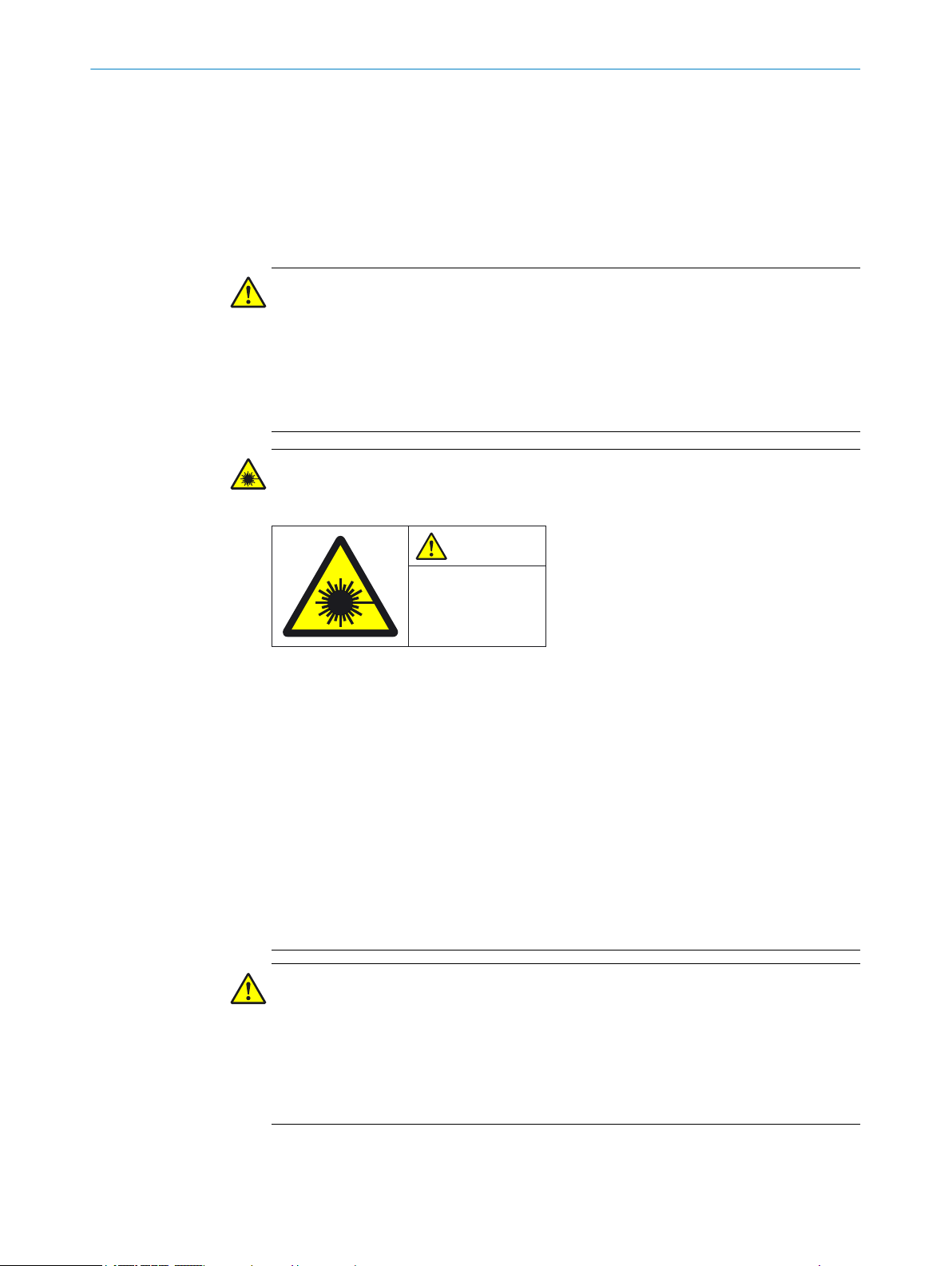
WARNING
In
visible laser radiation
Laser class 1M
Figure 1: Laser class 1M
T
his device complies with the following standards:
IEC 60825-1:2007/EN 60825-1:2007
•
IEC 60825-1:2014/EN 60825-1:2014
•
21 CFR 1040.10 and 1040.11, except for changes due to Laser Notice No. 50 of
•
24/06/2007
The safety laser scanner’s accessible laser is not hazardous as long as the beam cross
section is not reduced by optical instruments, such as magnifying glasses, lenses, tele‐
scopes.
The curved part of the optics cover is the outlet for the laser radiation.
The laser marking is located on the underside of the safety laser scanner.
You must comply with the latest version of the applicable laser safety regulations.
b
CAUTION
y operating or adjusting devices other than those specified in this document are
If an
used or other methods are employed, this can lead to dangerous exposure to radiation.
Only use the operating or adjusting devices specified in this document.
b
Only follow the methods specified in this document.
b
Do not open the housing, except for the purposes of the installation and mainte‐
b
nance work specified in these operating instructions.
10
O PE R AT I NG IN S TR U CT I ON S | microScan3 – EtherNet/IP™ 8020200/ZU95/2018-02-05 | SICK
Subject to change without notice
Page 11
2.2 Correct use
SAFETY INFORMATION 2
CAUTION
serving the safety laser scanner through optical instruments (such as magnifying
Ob
glasses, lenses, telescopes) may be hazardous for the eyes.
Do not look directly at the laser beam source using optical instruments.
b
The safety laser scanner is an electro-sensitive protective device (ESPE) and is suitable
or the following applications:
f
Hazardous area protection
•
Hazardous point protection
•
Access protection
•
Mobile hazardous area protection (protection of automated guided vehicles)
•
The safety laser scanner must only be used within the limits of the prescribed and
pecified technical data and operating conditions at all times.
s
Incorrect use, improper modification of or tampering with the safety laser scanner will
invalidate any warranty from SICK; in addition, any responsibility and liability of SICK for
damage and secondary damage caused by this is excluded.
Foreseeable misuse
DANGER
H
azard due to lack of effectiveness of the protective device
Persons and parts of the body to be protected may not be recognized in case of nonobservance.
The safety laser scanner works as an indirect protective measure and cannot provide
protection from pieces thrown from application nor from emitted radiation. Transparent
objects are not detected.
You must only use the safety laser scanner as an indirect protective measure.
b
The safety laser scanner is no
Outdoors
•
Underwater
•
In explosive environments
•
t suitable for the following applications, among others:
2.3 Requirements for personnel qualifications
The safety laser scanner must only be configured, installed, connected, commissioned
and ser
Project planning
viced by qualified safety personnel.
For project planning, a person is considered competent when he/she has expertise and
experience in the selection and use of protective devices on machines and is familiar
with the relevant technical rules and national work safety regulations.
Mechanical mounting
For mechanical mounting, a person is considered competent when he/she has the
expertise and experience in the relevant field and is sufficiently familiar with the appli‐
cation of the protective device on the machine that he/she can assess its operational
safety status.
8020200/ZU95/2018-02-05 | SICK O P ER A TI N G I NS T RU C TI O NS | microScan3 – EtherNet/IP™
Subject to change without notice
11
Page 12

AFETY INFORMATION
2 S
Electrical installation
F
or electrical installation, a person is considered competent when he/she has the
expertise and experience in the relevant field and is sufficiently familiar with the appli‐
cation of the protective device on the machine that he/she can assess its operational
safety status.
Configuration
For configuration, a person is considered competent when he/she has the expertise
and experience in the relevant field and is sufficiently familiar with the application of
the protective device on the machine that he/she can assess its work safety aspects.
Commissioning
For commissioning, a person is considered competent when he/she has the expertise
and experience in the relevant field and is sufficiently familiar with the application of
the protective device on the machine that he/she can assess its operational safety sta‐
tus.
Operation and maintenance
For operation and maintenance, a person is considered competent when he/she has
the expertise and experience in the relevant field and is sufficiently familiar with the
application of the protective device on the machine and has been instructed by the
machine operator in its operation.
An operator may clean the safety laser scanner and carry out specific thorough checks
following instruction. More information for the operator of the machine: see "Regular
cleaning", page 127, see "Operation", page 121.
12
O PE R AT I NG IN S TR U CT I ON S | microScan3 – EtherNet/IP™ 8020200/ZU95/2018-02-05 | SICK
Subject to change without notice
Page 13
3 Product description
t
t
∆t
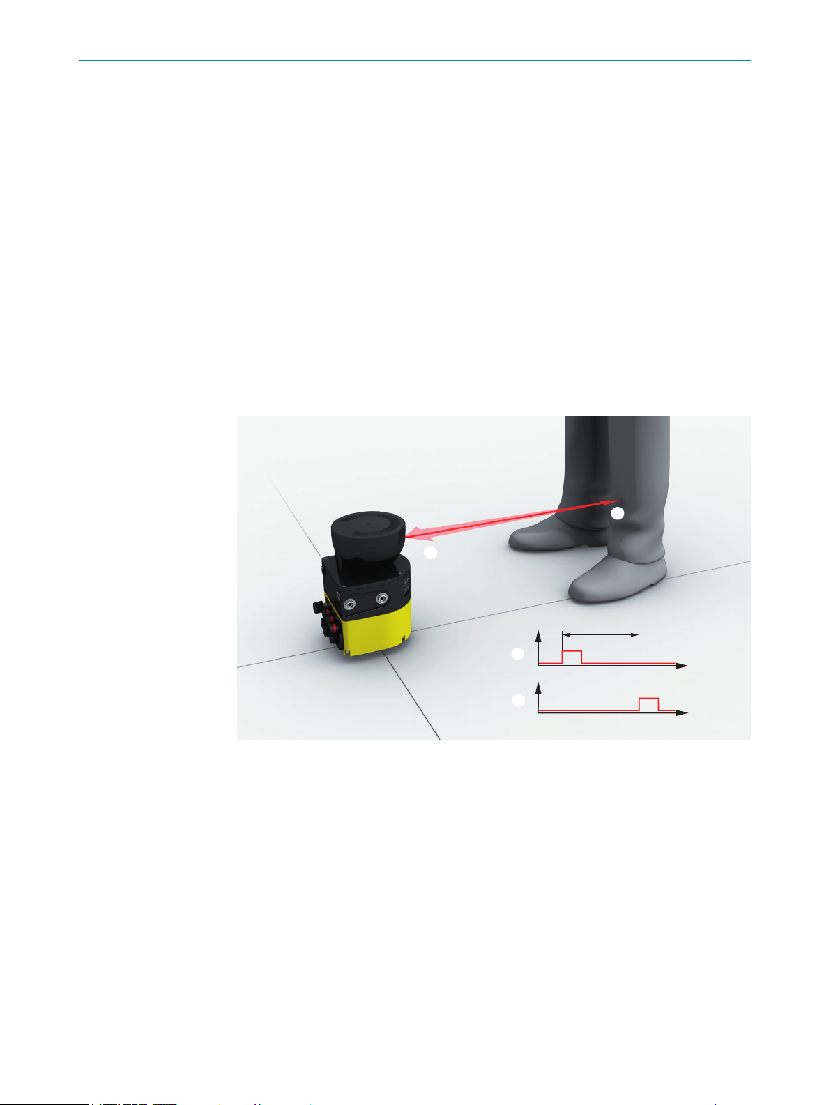
3.1 Setup and function
The safety laser scanner is an electro-sensitive protective device (ESPE), which twodimensionall
The safety laser scanner forms a protective field using the invisible laser beams. This
protective field protects the hazardous area and enables hazardous point protection,
access protection or hazardous area protection. As soon as an object is situated in the
protective field, the safety laser scanner signals the detection by means of a signal
change at the safety output (OSSD for example). The machine or its control must safely
analyze the signals (for example using a safe control or safety relays) and stop the dan‐
gerous state.
The safety laser scanner operates on the principle of time-of-flight measurement. It
emits light pulses in regular, very short intervals. If the light strikes an object, it is
reflected. The safety laser scanner receives the reflected light. The safety laser scanner
calculates the distance to the object based on the time interval between the moment of
transmission and moment of receipt (∆t).
PRODUCT DESCRIPTION 3
y scans its environment with infrared laser beams.
Figure 2: Principle of time-of-flight measurement
Transmitted light pulse
1
Reflected light pulse
2
A rotating mirror is situated in the safety laser scanner. The mirror deflects the light
pulse
s so that they scan a fan-shaped area.
8020200/ZU95/2018-02-05 | SICK O P ER A TI N G I NS T RU C TI O NS | microScan3 – EtherNet/IP™
Subject to change without notice
13
Page 14

227,5°
0°
90°
-47,5°
3 P
RODUCT DESCRIPTION
Figure 3: Light pulses scan an area
Angular resolution: the angular distance (in degrees) between 2 distance measurements
1
Scan cycle time and resolution
T
he time that the mirror requires for one rotation is called the scan cycle time. The
number of light pulses per unit time is constant. A change in the scan cycle time also
changes the number of light pulses per mirror rotation. This results in different angular
resolutions. The range for a given object resolution changes with the angular resolution.
The object resolution indicates the minimum size that an object must be to allow it to
be detected safely. Also, different response times result from a change to the scan
cycle time.
Slightly different scan cycle times can be used to minimize mutual interference in
neighboring safety laser scanners.
The resolution in protective fields can be set between 30 mm and 200 mm, according
to the intended purpose.
Geometry of the scan plane
T
he laser beams emitted cover a sector of a circle, so an object can be detected in an
area of up to 275°.
The sector of a circle covered ranges from –47.5° to 227.5°, where 90° denotes the
axis of the safety laser scanner from the back to the front. When viewing the safety
laser scanner from above, the direction of rotation of the mirror and the deflected light
pulses is counterclockwise, see figure 3.
14
O PE R AT I NG IN S TR U CT I ON S | microScan3 – EtherNet/IP™ 8020200/ZU95/2018-02-05 | SICK
Subject to change without notice
Page 15
3.2 Product characteristics
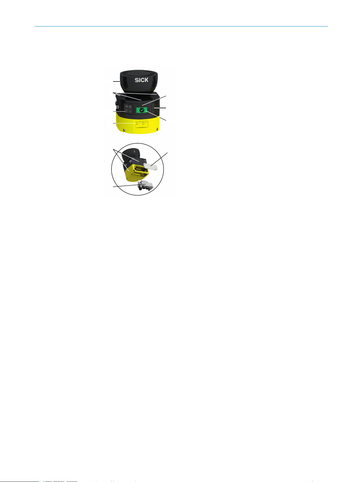
3.2.1 Device overview
PRODUCT DESCRIPTION 3
Figure 4: microScan3 – overview
Optics cover
1
Display
2
Keypad
3
USB port
4
Status LEDs
5
Additional LEDs
6
Network LEDs
7
Safety laser scanner without system plug
8
System plug
9
Cover plate
ß
Different variants of the safety laser scanner are available, see "V
ariants", page 16.
Further information about the variants see "Variant overview", page 150.
All variants have an optics cover and the rotating mirror is located below the optics
cover. The light pulses are emitted and the reflected light pulses are received through
the optics cover.
The display with 4 pushbuttons is located below the optics cover. The safety laser scan‐
ner also has a number of light emitting diodes, see "Status indicators", page 16, see
"Buttons and display", page 122.
Information about connections: see "Connections", page 17.
The safety laser scanner can be mounted and operated in any alignment. In this docu‐
ment, position and direction information is used as follows with respect to the safety
laser scanner, as long as different usage is not indicated separately:
The top is the side of the safety laser scanner on which the optics cover is located.
•
The bottom is the side of the safety laser scanner opposite the optics cover.
•
8020200/ZU95/2018-02-05 | SICK O P ER A TI N G I NS T RU C TI O NS | microScan3 – EtherNet/IP™
Subject to change without notice
15
Page 16

1 2 3 4
3 PRODUCT DESCRIPTION
•
•
3.2.2 Variants
The safety laser scanner is delivered in different variants. You will find an overview of
im
portant distinguishing features of the variants in the following. Further information
about the variants see "Variant overview", page 150.
The following properties differ in the variants:
•
•
Performance package
T
he Core and Pro performance packages feature a number of configurable fields and a
number of safety switching functions.
•
•
he front is the side of the safety laser scanner on which the display is located.
T
The 90° angle of the sector of a circle scanned by the safety laser scanner points
in this direction.
The back is the side of the safety laser scanner opposite the display. The sector of
a circle not scanned by the safety laser scanner lies in this direction.
Performance package
Maximum protective field range
microScan3 Core – EtherNet/IP™: 8 fields, 4 safety outputs via network
microScan3 Pro – EtherNet/IP™: 128 fields, 8 safety outputs via network
Integration in the control
he safety laser scanner communicates with the machine controller as follows:
T
•
Protective field range
here are two variants with different maximum protective field range:
T
•
•
3.2.3 Status indicators
The safety laser scanner outputs important status information using a number of light
emit
additional information.
4 status light emitting diodes are located directly above the display.
EtherNet/IP™ – CIP Safety™
4.0 m
5.5 m
ting diodes. The safety laser scanner has a graphical display and 4 pushbuttons for
16
Figure 5: Status LEDs
O PE R AT I NG IN S TR U CT I ON S | microScan3 – EtherNet/IP™ 8020200/ZU95/2018-02-05 | SICK
Subject to change without notice
Page 17

PRODUCT DESCRIPTION 3
Table 1: Status LEDs
Number Function Color Meaning
1
2
3
4
The OFF state and ON state light emitting diodes can be found in multiple locations on
t
he safety laser scanner. 3 additional sets are arranged in pairs on the base of the
optics cover. So the light emitting diodes can also be seen in many cases when it is not
possible to see the display, e.g. due to the mounting situation or because it is hidden
from the operator’s position.
The device has different light emitting diodes for every network interface. These net‐
work light emitting diodes are located below the display.
OFF state Red Lights up red when at least one
s
afety output is in the OFF state.
ON state Green Lights up green when at least one
safety output is in the ON state.
Warning field Yellow Shines yellow if at least one warning
field is interrupted.
Restart interlock Yellow Setup with reset: Flashes if the
estart interlock has been triggered.
r
Configuration with automated restart
after a time: Lights up while the con‐
figured time to restart expires.
3.2.4 Connections
3.2.5 System plug
More information about the meaning of the light emitting diodes see "Diagnostic LEDs",
page 135.
Depending on the configuration, the display shows current information about the safety
laser scanner’s status, see "Buttons and display", page 122.
1 x male connec
•
2 × female connector, M12, D-coding for Ethernet (EtherNet/IP – CIP Safety, data
•
tor, M12, A-coding for voltage supply
output, configuration, and diagnostics)
1 × female connector, USB 2.0 Mini-B for configuration and diagnosis
•
1)
A system plug is required to operate the safety laser scanner.
he metal plate with the connections is the system plug (see figure 4, page 15). The
T
system plug can either be mounted on the rear side or the underside.
The safety laser scanner’s internal configuration memory is integrated in the system
plug. The system plug and all connecting cables can remain at the installation site
when the safety laser scanner is replaced. The system plug is detached from the defec‐
tive safety laser scanner and connected to the new safety laser scanner. The new
safety laser scanner reads the configuration from the configuration memory when
switching on.
3.2.6 Field types
During operation, the safety laser scanner uses its laser beams continuously to check
whe
ther people or objects are present in one or more areas. The areas to be checked
are called fields. A distinction is made between the following field types, depending on
how the safety laser scanner is used:
Protective field
•
Reference contour field
•
1)
he USB connection may only be used temporarily and only for configuration and diagnostics.
T
8020200/ZU95/2018-02-05 | SICK O P ER A TI N G I NS T RU C TI O NS | microScan3 – EtherNet/IP™
Subject to change without notice
17
Page 18
3 P
RODUCT DESCRIPTION
ontour detection field
C
•
Warning field
•
Table 2: Field types and their function
Protective field Reference con‐
Safe switch off
cording to ISO
(ac
13849-1)
Max. sensing
range of
microScan3
Purpose Detection and
Yes (PL d) Yes (PL d) Yes (PL d) No
4.0 m or 5.5 m
(depends on vari‐
ant)
protection of peo‐
ple
t
our field
4.0 m or 5.5 m
(depends on vari‐
ant)
Tamper protec‐
tion
Contour detec‐
tion field
4.0 m or 5.5 m
(depends on vari‐
ant)
e.g. door monitor‐
ing
Warning field
40 m
Functional use
(no safety-rele‐
vant use)
Protective field
T
he protective field protects the hazardous area of a machine or vehicle. As soon as the
electro-sensitive protective device detects an object in the protective field, it switches
the associated safety outputs to the OFF state. This signal can be passed to controllers
resulting in the dangerous state coming to an end, e.g. to stop the machine or the vehi‐
cle.
18
Figure 6: Protective field, shown in red in this document
Reference contour field
T
he reference contour field monitors a contour of the environment. The safety laser
scanner switches all safety outputs to the OFF state if a contour does not match the set
parameters, because, for example, the mounting situation of the safety laser scanner
were changed.
National and international standards require or recommend that a reference contour is
monitored, if the safety laser scanner is used in vertical operation for hazardous point
protection or for access protection.
O PE R AT I NG IN S TR U CT I ON S | microScan3 – EtherNet/IP™ 8020200/ZU95/2018-02-05 | SICK
Subject to change without notice
Page 19
PRODUCT DESCRIPTION 3
The reference contour field detects unintentional and intentional changes to the posi‐
t
ion or alignment of the safety laser scanner. Unintentional changes may be caused by
vibrations for example. An example of an intentional change is deliberate tampering to
disable the safety laser scanner’s functionality.
Figure 7: Reference contour field, shown in blue-green in this document
Contour detection field
T
he contour detection field monitors a contour of the environment. The safety laser
scanner switches the associated safety outputs to the OFF state if a contour does not
match the set parameters, because, for example, a door or flap is open.
The contour detection field is used for detecting changes in the environment and only
switches the outputs in the current monitoring case. By contrast, the reference contour
field is used for detecting changes at the safety laser scanner and switches all safety
outputs.
Warning field
T
he warning field monitors larger areas than the protective field. Simple switching func‐
tions can be triggered with the warning field, e.g. a warning light or an acoustic signal
can be triggered if a person approaches, even before the person enters the protective
field.
The warning field must not be used for safety-relevant tasks.
8020200/ZU95/2018-02-05 | SICK O P ER A TI N G I NS T RU C TI O NS | microScan3 – EtherNet/IP™
Subject to change without notice
19
Page 20
RODUCT DESCRIPTION
3 P
Figure 8: Warning field, shown in yellow or orange in this document
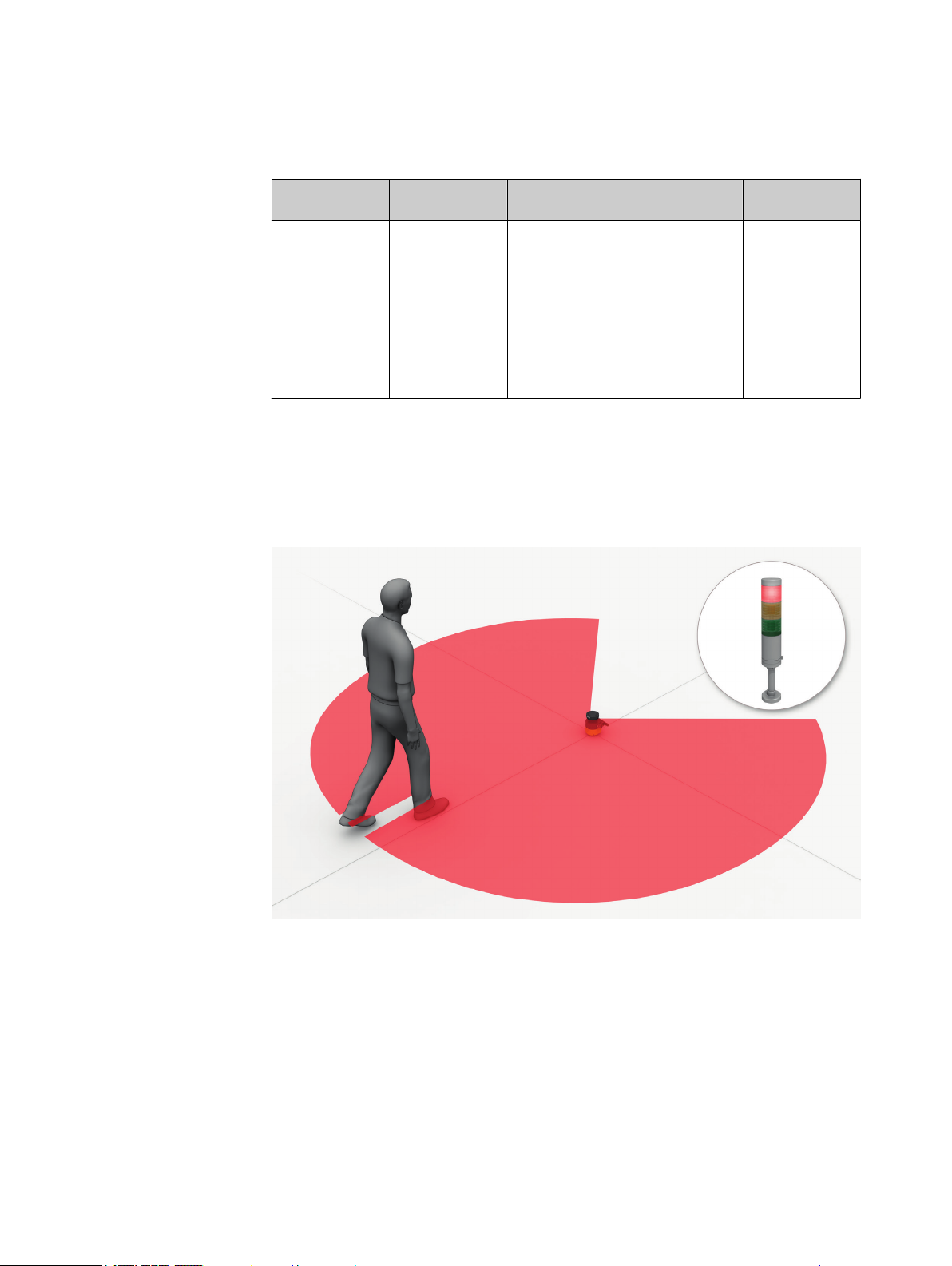
3.2.7 Field set
A field set consists of one or more fields. The fields in a field set are monitored simulta‐
neousl
y.
A field set can contain various types of field.
A typical application is the use of a protective field with one or more warning fields: if a
vehicle approaches a person, a warning field triggers an optical or acoustic signal. If the
person does not react to this and the vehicle continues to approach, the safety laser
scanner detects an object in the protective field and switches the associated safety out‐
puts to the OFF state. The vehicle stops before it reaches the person.
20
Figure 9: Field set, consisting of one protective field (red) and 2 warning fields (orange and yel‐
lo
w)
O PE R AT I NG IN S TR U CT I ON S | microScan3 – EtherNet/IP™ 8020200/ZU95/2018-02-05 | SICK
Subject to change without notice
Page 21

3.2.8 Monitoring case
A monitoring case signals the machine status to the safety laser scanner. The safety
la
therefore a particular machine status.
If a machine, e.g., has various operational statuses, a monitoring case can be assigned
to each operational status. The safety laser scanner receives a defined signal for the
current operational status via the safety-related network. If there is a change of signal,
the safety laser scanner switches from one monitoring case to the monitoring case that
is assigned to the new signal (as well as the new operational status). Generally, one
field set is assigned to each monitoring case.
PRODUCT DESCRIPTION 3
ser scanner activates the field set, which is assigned to the monitoring case and
Figure 10: Monitoring case 1 with field set 1
Figure 11: Monitoring case 2 with field set 2
8020200/ZU95/2018-02-05 | SICK O P ER A TI N G I NS T RU C TI O NS | microScan3 – EtherNet/IP™
Subject to change without notice
21
Page 22
3 P
RODUCT DESCRIPTION
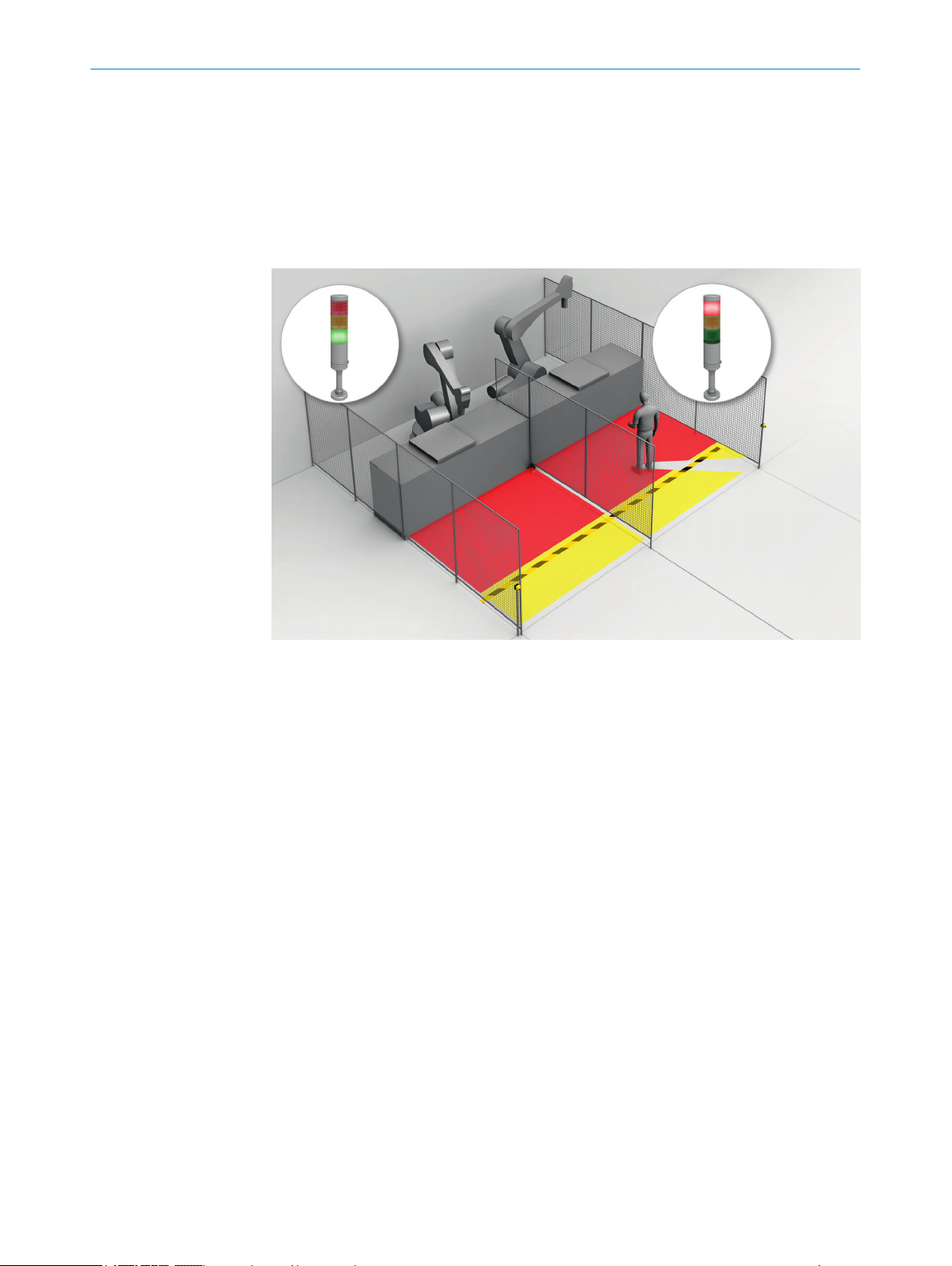
3.2.9 Simultaneous monitoring
The safety laser scanner can monitor several field sets in one monitoring case (e.g. haz‐
ar
dous area to the left and hazardous area to the right). The field sets can affect differ‐
ent safety outputs in variants with several safety outputs.
For example, they can protect 2 machines with only one safety laser scanner.
In order to configure simultaneous monitoring, assign several field sets to a monitoring
case in Safety Designer, see "Assigning field sets", page 108.
Figure 12: Simultaneous monitoring
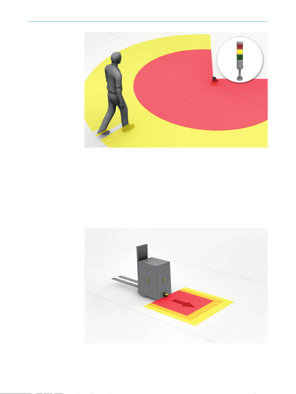
3.3 Example applications
Hazardous area protection
In ha
zardous area protection, people are detected if they stay in a defined area.
This type of protective device is suitable for machines, where it is possible to see a haz‐
ardous area completely from the reset pushbutton. When the hazardous area is
entered, a stop signal is triggered and starting is prevented.
22
O PE R AT I NG IN S TR U CT I ON S | microScan3 – EtherNet/IP™ 8020200/ZU95/2018-02-05 | SICK
Subject to change without notice
Page 23
PRODUCT DESCRIPTION 3
Figure 13: Hazardous area protection: detection of the presence of a person in the hazardous
ar
ea
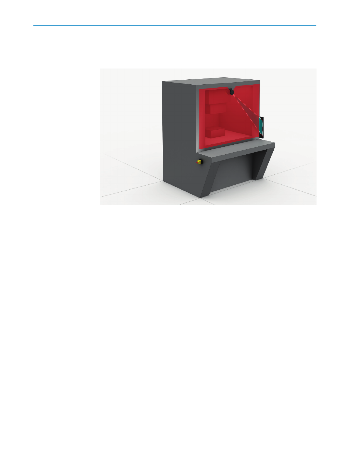
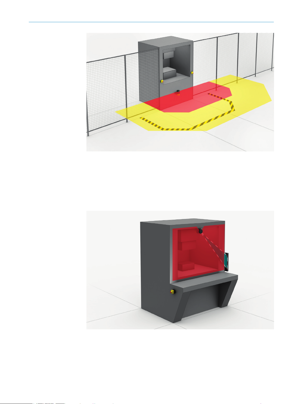
Hazardous point protection
In hazardous point protection, the approach is detected very close to the hazardous
point.
The advantage of this type of protective device is that it is possible to have a short mini‐
mum distance and the operator can work more ergonomically.
Figure 14: Hazardous point protection: hand detection
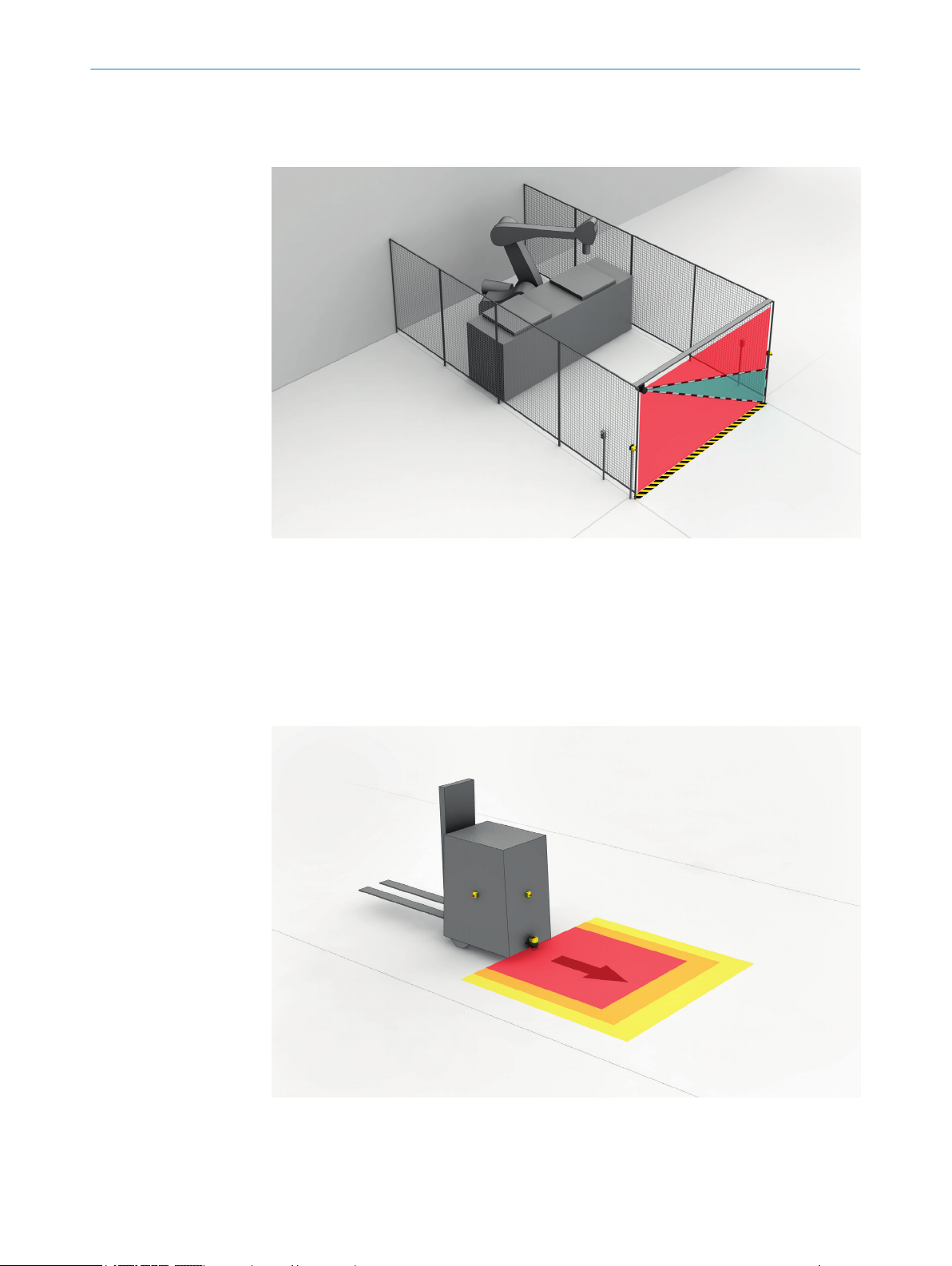
Access protection
In ac
cess protection, people are detected if their whole body passes through the protec‐
tive field.
8020200/ZU95/2018-02-05 | SICK O P ER A TI N G I NS T RU C TI O NS | microScan3 – EtherNet/IP™
Subject to change without notice
23
Page 24
3 P
RODUCT DESCRIPTION
This type of protective device is used for the protection of access to hazardous areas.
W
hen the hazardous area is entered, a stop signal is triggered. A person standing
behind the protective device will not be detected by the ESPE.
Figure 15: Access protection: detection of a person when accessing a hazardous area
Mobile hazardous area protection
Mobile ha
zardous area protection is suitable for AGVs (automated guided vehicles),
cranes and forklifts, to protect people when vehicles are moving or docking at a fixed
station.
The safety laser scanner monitors the area in the direction of travel and stops the vehi‐
cle as soon as an object is located in the protective field.
24
Figure 16: Mobile hazardous area protection: detection of a person when a vehicle approaches
O PE R AT I NG IN S TR U CT I ON S | microScan3 – EtherNet/IP™ 8020200/ZU95/2018-02-05 | SICK
Subject to change without notice
Page 25
4 Project planning
4.1 Manufacturer of the machine
DANGER
H
azard due to lack of effectiveness of the protective device
Persons and parts of the body to be protected may not be recognized in case of nonobservance.
Use of the safety laser scanner requires a risk assessment. Check whether addi‐
b
tional protective measures are required.
Comply with the applicable national regulations derived from the application (e.g.,
b
work safety regulations, safety rules, or other relevant safety guidelines).
Apart from the procedures described in this document, the components of the
b
safety laser scanner must not be opened.
The safety laser scanner must not be tampered with or changed.
b
Improper repair of the protective device can lead to a loss of the protective func‐
b
tion. The protective device must only be repaired by the manufacturer or by some‐
one authorized by the manufacturer.
PROJECT PLANNING 4
4.2 Operator of the machine
DANGER
H
azard due to lack of effectiveness of the protective device
Persons and parts of the body to be protected may not be recognized in case of nonobservance.
Changes to the electrical integration of the safety laser scanner in the machine
b
control and changes to the mechanical mounting of the safety laser scanner
necessitate a new risk assessment. The results of this risk assessment may
require the operator of the machine to meet a manufacturer’s obligations.
Changes to the device’s configuration may impair the protective function. The
b
effectiveness of the protective device must be checked after any change to the
configuration. The person carrying out the change is also responsible for maintain‐
ing the protective function of the device.
Apart from the procedures described in this document, the components of the
b
safety laser scanner must not be opened.
The safety laser scanner must not be tampered with or changed.
b
Improper repair of the protective device can lead to a loss of the protective func‐
b
tion. The protective device must only be repaired by the manufacturer or by some‐
one authorized by the manufacturer.
4.3 Assembly
This chapter contains important information about the design.
Information about the individual steps for mounting the device: see "Mounting",
page 67.
8020200/ZU95/2018-02-05 | SICK O P ER A TI N G I NS T RU C TI O NS | microScan3 – EtherNet/IP™
Subject to change without notice
25
Page 26
4 P
ROJECT PLANNING
DANGER
azard due to lack of effectiveness of the protective device
H
Persons and parts of the body to be protected may not be recognized in case of non-
observance.
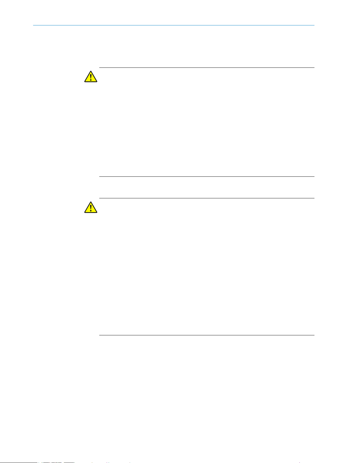
Make sure that the following design requirements are met so that the safety laser
b
scanner can fulfill its protective function.
he safety laser scanner must be affixed so that people or parts of the body are
T
•
reliably detected upon entry into the hazardous area.
The safety laser scanner must be affixed so that no mirrors or other exceedingly
•
reflective objects are in the protective field.
The safety laser scanner must be affixed so that no small objects (e.g. cables) are
•
in the protective field, even if the safety outputs do not switch to the OFF state as a
result.
The safety laser scanner must be affixed so that no obstacles disrupt the safety
•
laser scanner’s field of view. Take additional protective measures if a risk arises
due to unavoidable obstacles.
If people can stay between the protective device and the hazardous point without
•
being detected, check if additional protective measures (e.g. restart interlock) are
required.
Reaching under, over and around, crawling beneath and stepping over the safety
•
laser scanner, as well as moving it, must be prevented.
Figure 17: Prevent crawling beneath
Figure 18: Prevent stepping over
26
O PE R AT I NG IN S TR U CT I ON S | microScan3 – EtherNet/IP™ 8020200/ZU95/2018-02-05 | SICK
Subject to change without notice
Page 27

PROJECT PLANNING 4
DANGER
azard due to lack of effectiveness of the protective device
H
Persons and parts of the body to be protected may not be recognized in case of non-
observance.
The optical beam path must not be disrupted, e.g. if the system is incorporated into
paneling.
Do not attach an additional front screen.
b
If a viewing slit is required, make sure that its size is sufficient, see "Dimensional
b
drawings", page 174.
NOTE
ertain optical and electromagnetic ambient conditions can affect the safety laser
C
scanner. This may impair the machine’s availability. That is to say, the safety laser scan‐
ner switches the machine off, although no people are located in the protective field.
Take note of the following for a high level of availability:
Avoid having strong electric fields in the vicinity of the safety laser scanner. These
b
may be caused by nearby welding or induction cables, for example.
Prevent condensation forming on the optics cover.
b
4.3.1 Protection against interference from systems in close proximity to each other
A safety laser scanner can be influenced by the beams from a different laser source in
close proximity to it, e.g. by another laser scanner. This may impair the machine’s avail‐
ability. That is to say, the affected safety laser scanner switches the machine off,
although no people are situated in the protective field.
You can use the following measures to increase the availability:
The safety laser scanner has a function for interference protection. The scan cycle
•
time is adjusted in small increments. You can increase the availability by choosing
different modes for interference protection in adjacent safety laser scanners, see
"Additional interference protection", page 93.
Higher multiple sampling reduces the likelihood of a laser source influencing the
•
safety laser scanner. You can increase the availability by setting multiple sampling
to the highest value permitted in your application, while taking minimum distances
into account, see "Multiple sampling", page 91.
You can further increase the availability by choosing a suitable mounting method,
•
see "Mounting methods for protection from interference from systems in close
proximity", page 189.
You can check the safety laser scanner’s beam path using the Scanfinder LS-80L (part
no. 6020756).
NOTE
Y
ou must comply with the standard ISO 13855 when choosing the mounting method.
8020200/ZU95/2018-02-05 | SICK O P ER A TI N G I NS T RU C TI O NS | microScan3 – EtherNet/IP™
Subject to change without notice
27
Page 28
4 P
ROJECT PLANNING
4.3.2 Preventing unprotected areas
DANGER
Hazard due to lack of effectiveness of the protective device
Persons and parts of the body to be protected may not be recognized in case of non-
observance.
Mount the safety laser scanner so that people cannot enter unsecured areas. Take one
or more of the measures described below as required:
Attach deflector plates to prevent anyone standing behind.
b
Mount the safety laser scanner in an undercut.
b
Mount the safety laser scanner in the paneling of the machine or vehicle.
b
Mount a frame to prevent access to the area.
b
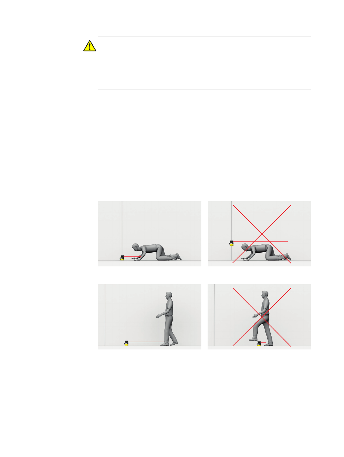
Unsecured areas behind the safety laser scanner
epending on the mounting situation, areas may result, which cannot be detected by
D
the safety laser scanner.
The undetected areas become larger if the safety laser scanner is mounted using a
mounting kit.
28
Figure 19: Unsecured areas
Length of the unsecured area
1
Width of the unsecured area
2
Area where detection capability is restricted
lose proximity (50 mm wide area in front of the optics cover), the detection capabil‐
In c
ity of the safety laser scanner may be restricted. If required, this area must be secured
using an undercut or frame, for example.
O PE R AT I NG IN S TR U CT I ON S | microScan3 – EtherNet/IP™ 8020200/ZU95/2018-02-05 | SICK
Subject to change without notice
Page 29
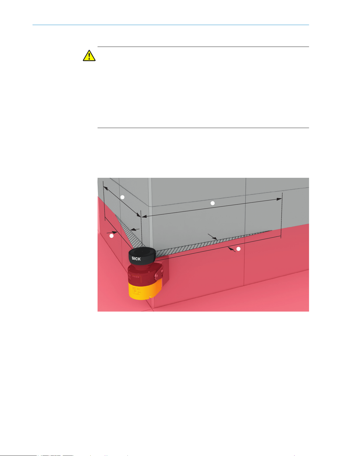
Mounting with deflector plates
PROJECT PLANNING 4
Figure 20: Mounting with deflector plates (example)
b Attach the deflector plates 1 so that it is not possible to step into unsecured
areas.
Attach the deflector plates so that they lie outside the scan plane.
b
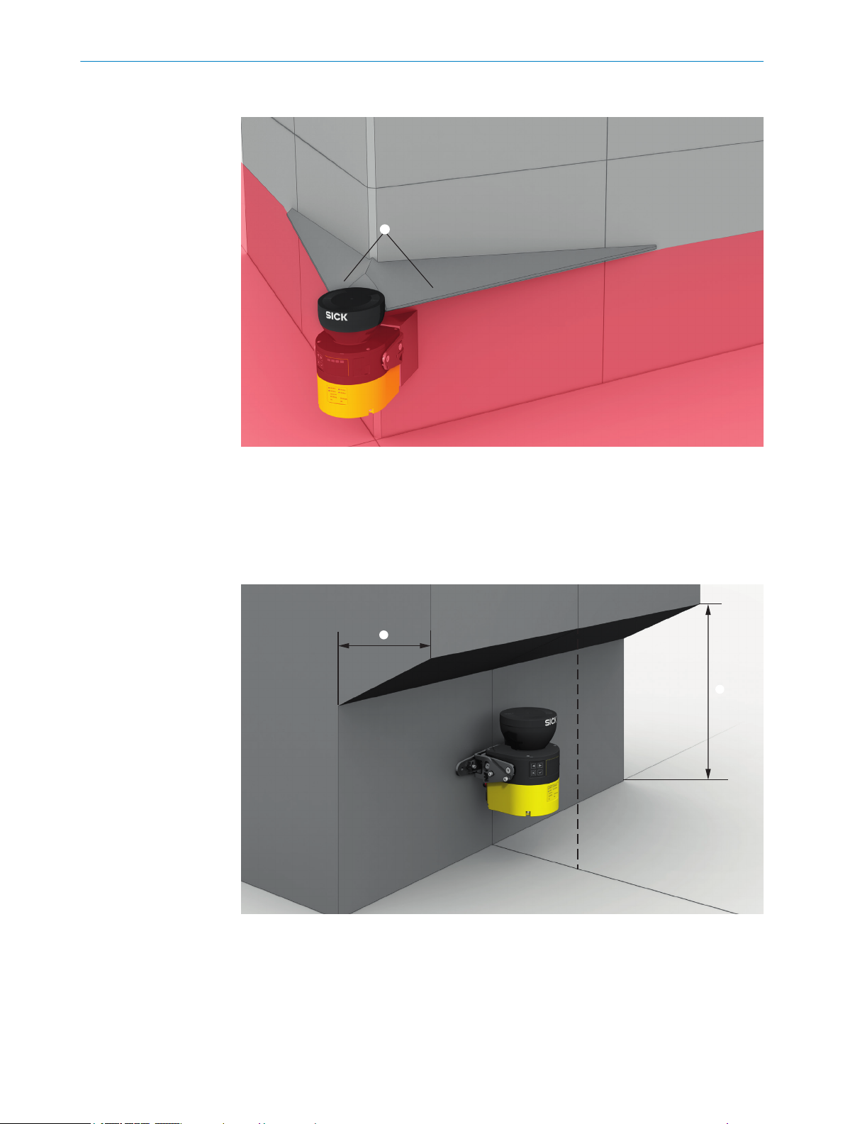
Mounting in an undercut
Figure 21: Mounting in an undercut (example)
b
Mount t
he safety laser scanner in an undercut so that no-one can enter the unse‐
cured areas.
b Make the undercut at least deep enough 1, that it covers the unsecured areas
completely and no one can enter the unsecured areas.
b Prevent crawling beneath the undercut. Design the undercut to be so low 2, that
no one can crawl into it.
8020200/ZU95/2018-02-05 | SICK O P ER A TI N G I NS T RU C TI O NS | microScan3 – EtherNet/IP™
Subject to change without notice
29
Page 30
4 P
ROJECT PLANNING
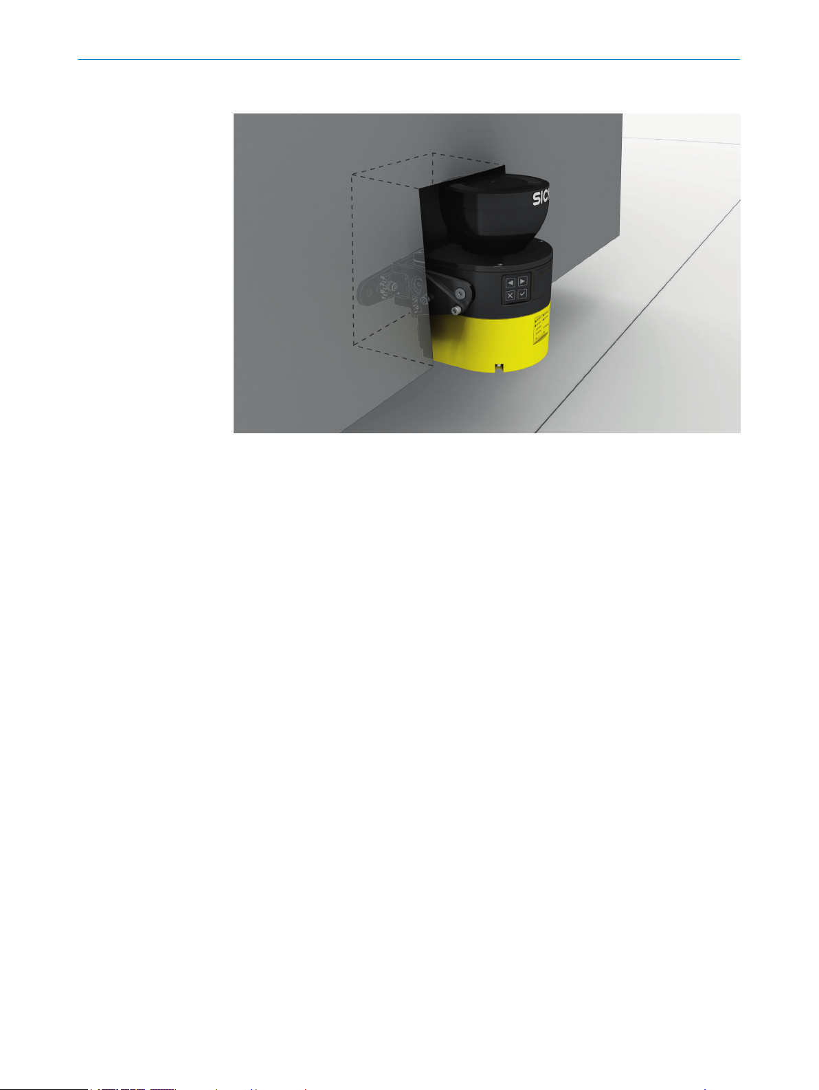
Mounting in the machine or vehicle’s paneling
Figure 22: Mounting in vehicle paneling (example)
If a v
b
iewing slit is required, make sure that its size is sufficient, see "Dimensional
drawings", page 174.
4.3.3 Response time of the safety laser scanner
The safety laser scanner’s response time must be taken into account, among other
t
hings, so that the safety laser scanner can be positioned in a suitable location and the
protective fields can be sized correctly.
The response times are specified in the technical data, see "Response times",
page 155.
The response time of the safety laser scanner resulting from current settings is shown
in Safety Designer.
4.3.4 Reference contour monitoring
Reference contour field
T
he reference contour field monitors a contour of the environment. The safety laser
scanner switches all safety outputs to the OFF state if a contour does not match the set
parameters, because, for example, the mounting situation of the safety laser scanner
were changed.
National and international standards require or recommend that a reference contour is
monitored, if the safety laser scanner is used in vertical operation for hazardous point
protection or for access protection.
30
The reference contour field detects unintentional and intentional changes to the posi‐
tion or alignment of the safety laser scanner. Unintentional changes may be caused by
vibrations for example. An example of an intentional change is deliberate tampering to
disable the safety laser scanner’s functionality.
Vertical operation
N
ational and international standards require or recommend that a reference contour is
monitored, if the angle between access direction and scan plane exceeds +30°.
O PE R AT I NG IN S TR U CT I ON S | microScan3 – EtherNet/IP™ 8020200/ZU95/2018-02-05 | SICK
Subject to change without notice
Page 31

PROJECT PLANNING 4
DANGER
azard due to lack of effectiveness of the protective device
H
Persons and parts of the body to be protected may not be recognized in case of non-
observance.
Use a contour from the environment as a reference to protect the protective device
b
from inadvertent adjustment or tampering.
Configuring the reference contour field during vertical operation
N
ote the following points in particular when configuring the reference contour field:
In many cases, it makes sense to use lateral vertical passage boundaries (e.g.
•
door frames) and the floor as a reference.
The reference contour field has a tolerance band, which can be set, around the
•
contour. If the safety laser scanner does not detect the contour within the toler‐
ance band, all safety outputs switch to the OFF state.
For high availability, it is recommended to set the tolerance band to 65 mm
°
positive tolerance (far) and 65 mm negative tolerance (near).
Make sure that the tolerance band is not too wide. The reference contour
°
field must detect a change in the position or alignment of the safety laser
scanner before a dangerous gap is created between the protective field and
mechanical limit.
The following requirements apply to the protective field with respect to the refer‐
•
ence contour field:
Access protection:
°
°
You can define a number of contours in the reference contour field and so monitor
•
various areas in the environment.
If the reference contour represents the edge of the protected opening,
•
the distance between the edge of the protected opening and the protec‐
tive field must be no more than 100 mm wide. A distance of 65 mm is
recommended for high availability and sufficient protection.
If the reference contour does not represent the edge of the protected
•
opening, the protective field must be larger than the protected opening.
The required overrun (o) is calculated using the same formula as for haz‐
ardous point protection.
Hazardous point protection: the protective field must be larger than the pro‐
tected opening. The required overrun (o) is calculated using the following for‐
mula:
o ≥ 130 mm – d
where:
verrun of the protective field over the opening
o = o
•
d = set resolution
•
8020200/ZU95/2018-02-05 | SICK O P ER A TI N G I NS T RU C TI O NS | microScan3 – EtherNet/IP™
Subject to change without notice
31
Page 32

1 2
3
1
2
ROJECT PLANNING
4 P
Figure 23: Tolerance band of the reference contour field (protective field within the protected
openin
g, edge of the protected opening = reference contour)
TZ = tolerance band of the reference contour field
1
Distance of the protective field from the contour, to ensure availability
2
Figure 24: Overrun of the protective field in front of an opening
TZ = tolerance band of the reference contour field
1
Distance of the protective field from the contour, to ensure availability
2
o = overrun of the protective field over the opening
3
4.3.5 Monitoring case switching time
When switching between monitoring cases, it is possible that a person may already be
in t
he newly activated protective field when switching takes place. Only switching in time
(namely before the danger arises for the person at this location) ensures protection.
32
O PE R AT I NG IN S TR U CT I ON S | microScan3 – EtherNet/IP™ 8020200/ZU95/2018-02-05 | SICK
Subject to change without notice
Page 33

PROJECT PLANNING 4
DANGER
azard due to lack of effectiveness of the protective device
H
Switching of the monitoring case should be timed so that the safety laser scanner
b
detects a person in the protective field with a sufficient minimum distance, before
the dangerous state occurs.
DANGER
H
azard due to lack of effectiveness of the protective device
Persons or parts of the body to be protected may not be recognized or not recognized in
time in case of non-observance.
In addition to the parameters considered below, the switching signal’s propagation
delay time up to the protective device also influences the switching duration. These
include the network cycle time and the processing time of a control, for example.
Take account of the switching signal’s propagation delay time up to the protective
b
device.
In some cases, the process of switching between monitoring cases takes so long that
t
he new monitoring case is not available inside the response time provided. This means
that it may not be possible to detect a person in the protective field in time. In cases
like this, you must start switching between monitoring cases earlier.
The following parameters influence the duration of the process:
The set input delay (see "Input delay ", page 106).
•
The processing time for the chosen input.
•
You calculate when to switch between monitoring cases as follows
First calculate how long it takes to switch between monitoring cases:
1.
t
= tID + t
CSR
I
where:
t
= time required for switching between monitoring cases in milliseconds
C
SR
°
(ms)
tID = input delay for the control inputs in milliseconds (ms) (only for Assembly
°
100)
tI = processing time for the selected switching type in milliseconds (ms)
°
Switching signal via network: tI = 28 ms
•
2. Then calculate how much time is available in the response time for switching
between monitoring cases:
= (n – nCS) × t
t
SA
C
S
where:
t
= time available for switching between monitoring cases in milliseconds
C
SA
°
(ms)
n = set multiple sampling (default: n = 2)
°
nCS = multiple sampling after switching between monitoring cases (with set‐
°
ting Fast (presetting): nCS = 1, with setting Reliable: nCS = n – 1, with setting
User-defined: nCS ≤ n – 1)
tS = scan cycle time (poss. incl. supplement due to interference protection) in
°
milliseconds (ms)
3. Then check whether there is enough time available for switching between monitor‐
ing cases:
If t
≥ t
: earlier start is not necessary.
CSR
< t
: you must start switching between monitoring cases earlier. The
CSR
required is: t
CSP
CSP
= t
CSR
– t
CSA
If t
CSA
CSA
°
°
time advance t
8020200/ZU95/2018-02-05 | SICK O P ER A TI N G I NS T RU C TI O NS | microScan3 – EtherNet/IP™
Subject to change without notice
33
Page 34

S
S
4 P
ROJECT PLANNING
NOTE
In some c
ases, it is not possible to define when to switch (for example because pro‐
cessing times of the machine vary) or the time advance means that the monitoring of
an area finishes too early. Follow one of the following recommendations in these cases:
Allow the two protective fields to partially overlap.
b
Temporarily monitor both hazardous areas simultaneously.
b
4.3.6 Hazardous area protection
The safety laser scanner is mounted with a horizontal scan plane in a stationary appli‐
c
ation, for example on a machine where the hazardous area is not completely sur‐
rounded by a physical guard. During hazardous area protection, the safety laser scan‐
ner detects a person’s legs. The protective field is parallel to the person’s direction of
approach.
34
Figure 25: Stationary application with horizontal scan plane for hazardous area protection
NOTE
k the outline of the protective field boundaries on the floor after you have worked
Mar
out the protective field size. By doing this, you allow machine operators to see the pro‐
tective field boundaries and make it easier to thoroughly check the protective function
at a later date.
Protective field
T
he protective field must be designed so that it detects a person at a minimum dis‐
tance from the hazardous point. This distance is required to prevent a person or part of
their body from reaching the hazardous area before the end of the machine’s danger‐
ous state.
In hazardous area protection, the minimum distance typically defines the protective
field size required.
If you define a number of monitoring cases with different protective fields, you must cal‐
culate the protective field size separately for each protective field used.
In many cases, a resolution of 50 mm or 70 mm is suitable for hazardous area protec‐
tion.
O PE R AT I NG IN S TR U CT I ON S | microScan3 – EtherNet/IP™ 8020200/ZU95/2018-02-05 | SICK
Subject to change without notice
Page 35

PROJECT PLANNING 4
DANGER
azard due to lack of effectiveness of the protective device
H
In the case of non-compliance, it is possible that the dangerous state of the machine
may not be stopped or not stopped in a timely manner.
1. Calculate the required minimum distance for your machine using the following for‐
mulas and examples.
2. Take this calculation and the specifications in these instructions into account
when mounting the safety laser scanner.
3. Take this calculation and the specifications in these instructions into account
when configuring the safety laser scanner.
DANGER
azard due to lack of effectiveness of the protective device
H
Persons and parts of the body to be protected may not be recognized in case of non-
observance.
Body parts to be protected may not be detected under coarse resolution.
Use a resolution of 70 mm or finer for hazardous area protection.
b
For hazardous area protection with a resolution of 70 mm: make sure that it is
b
possible to detect a human leg.
For hazardous area protection with a resolution of 70 mm: mount the safety laser
b
scanner at a height of at least 300 mm (height of the scan plane).
If it is not possible to mount the safety laser scanner at a height of at least
b
300 mm, use a resolution of 50 mm.
NOTE
he protective field needs to be as small as possible, you may have to calculate the
If t
minimum distance multiple times with different scan cycle times (iterative calculation)
because of various dependencies.
2)
Always take the actual response time into account when calculating the minimum dis‐
tance, see "Response times", page 155.
1. First calculate the minimum distance on the basis of the response time for a scan
cycle time of 30 ms.
2. If the calculated minimum distance is larger than the resulting protective field
range (see "Protective field range", page 156), recalculate the minimum distance
on the basis of the response time for a scan cycle time of 40 ms.
Calculating minimum distance
T
he calculation of the minimum distance is based on international or national stan‐
dards and statutory requirements applicable at the place of installation of the machine.
If the minimum distance is calculated according to ISO 13855, then it depends on the
following points:
Machine stopping time (time interval between triggering the sensor function and
•
the end of the machine’s dangerous state, including signal propagation times in
the network and processing time in the control)
Response time of the protective device, see "Response times", page 155
•
Reach or approach speed of the person
•
Resolution (detection capability) of the safety laser scanner
•
Type of approach: parallel
•
Parameters specified based on the application
•
2)
he required minimum distance depends on the response time, among other things, and therefore on the scan cycle time. The protective
T
field range likewise depends on the scan cycle time: the protective field range is shorter for a faster scan cycle time.
8020200/ZU95/2018-02-05 | SICK O P ER A TI N G I NS T RU C TI O NS | microScan3 – EtherNet/IP™
Subject to change without notice
35
Page 36

4 PROJECT PLANNING
Supplement
•
Supplement to protect against reaching over
•
Height of the scan plane
•
Switching time between monitoring cases
•
NOTE
e information is available in the ISO 13855 standard and in the Guide for Safe
Mor
Machinery.
NOTE
SIC
K offers a stopping/run-down time measurement service in many countries.
Calculation example of the minimum distance S according to ISO 13855
he example shows the calculation of the minimum distance for parallel approach to
T
the protective field. Depending on the application and the ambient conditions a differ‐
ent calculation may be required. (e.g., a protective field or at an arbitrary angle to the
direction of approach or an indirect approach)
Calculate S using the following formula:
b
S = 1600 mm/s × T + 65 mm + ZR + C
where:
°
°
°
°
The reach/approach speed is already included in the formula.
s for general and, possibly, reflection-based measurement errors
S = minimum dis
T = stopping/run-down time for the entire system in seconds (s)
(Response time of the safety laser scanner + machine’s stopping/run-down
ime, incl. response time of the machine’s control system and signal propaga‐
t
tion time)
ZR = supplement f
(mm)
C = supplement to protect against reaching over in millimeters (mm)
tance in millimeters (mm)
or reflection-based measurement errors in millimeters
Supplement ZR f
If there is a retroreflector in the vicinity of the protective device (distance of the retrore‐
flector from protective field ≤ 6 m), you must take the supplement ZR = 350 mm into
account.
Supplement C to protect against reaching over
U
nder certain circumstances, a person can reach the hazardous area by reaching over,
before the protective device stops the dangerous state. Supplement C prevents this.
or reflection-based measurement errors
36
O PE R AT I NG IN S TR U CT I ON S | microScan3 – EtherNet/IP™ 8020200/ZU95/2018-02-05 | SICK
Subject to change without notice
Page 37

D
H ≈ 0 mm
C = 1200 mm
D
H = 875 mm
C = 850 mm
PROJECT PLANNING 4
Figure 26: Protection against reaching over when mounted low (dimensions in mm)
Figure 27: Protection against reaching over when mounted high (dimensions in mm)
he necessary supplement to the minimum distance depends on the height of the pro‐
T
tective field’s scan plane. The supplement is larger if the safety laser scanner is affixed
low-down than if it is affixed high-up.
Calculating the supplement C
If y
b
ou have sufficient free space in front of your machine, use value 1200 mm as
the supplement C.
If you want to keep the minimum distance as low as possible, use the following
b
formula to calculate C:
C = 1200 mm – (0.4 × HD)
where:
HD = hei
°
8020200/ZU95/2018-02-05 | SICK O P ER A TI N G I NS T RU C TI O NS | microScan3 – EtherNet/IP™
Subject to change without notice
ght of the protective field above the floor in millimeters (mm).
37
Page 38

4 PROJECT PLANNING
✓
✓
he result is C ≥ 850 mm, then use the calculated value as supplement C.
If t
If the result is C < 850 mm, then use C = 850 mm (this value corresponds to an
arm's length and is valid as a minimum supplement to protect against reaching
over).
Height of the scan plane
DANGER
azard due to lack of effectiveness of the protective device
H
It is possible to get around the protective device by crawling beneath.
Prevent people from being able to crawl beneath the protective field by mounting
b
the safety laser scanner appropriately.
If you mount the protective device higher than 300 mm, you must use additional
b
measures to prevent crawling beneath.
If you choose a resolution of 70 mm f
or hazardous area protection, it is not possible
under certain circumstances to detect a human leg. This is because a beam does not
hit the leg. Rather, the beams pass by the sides of the ankle (see figure 28, page 39).
If you mount the safety laser scanner at a height of at least 300 mm (height of the scan
plane), the scan plane is at calf height and the leg is even detected at a resolution of
70 mm (see figure 29, page 39).
DANGER
H
azard due to lack of effectiveness of the protective device
Persons and parts of the body to be protected may not be recognized in case of nonobservance.
Body parts to be protected may not be detected under coarse resolution.
Use a resolution of 70 mm or finer for hazardous area protection.
b
For hazardous area protection with a resolution of 70 mm: make sure that it is
b
possible to detect a human leg.
For hazardous area protection with a resolution of 70 mm: mount the safety laser
b
scanner at a height of at least 300 mm (height of the scan plane).
If it is not possible to mount the safety laser scanner at a height of at least
b
300 mm, use a resolution of 50 mm.
38
O PE R AT I NG IN S TR U CT I ON S | microScan3 – EtherNet/IP™ 8020200/ZU95/2018-02-05 | SICK
Subject to change without notice
Page 39

D
H
Figure 28: Scan plane at ankle height
D
H
PROJECT PLANNING 4
Figure 29: Scan plane at calf height
he height of the protective field (scan plane) is predefined and is less than 300 mm,
If t
you can calculate the required resolution using the following formula:
dr = HD/15 + 50 mm
where:
dr = coarsest permissible resolution of the safety laser scanner in millimeters
•
(mm)
HD = height of the protective field above the floor in millimeters (mm)
•
The safety laser scanner’s resolution can be set to the predefined value d. If the
b
result dr does not match any of these values, choose a finer resolution (d ≤ dr).
8020200/ZU95/2018-02-05 | SICK O P ER A TI N G I NS T RU C TI O NS | microScan3 – EtherNet/IP™
Subject to change without notice
39
Page 40

1
4 P
ROJECT PLANNING
Distance from walls
T
he availability may be impaired if the protective field stretches as far as a wall or a
different object. So, plan to have a space between the protective field and the object. A
space of approx. 65 mm is recommended to ensure availability.
Figure 30: Distance of the protective field from the wall
Recommended distance of the protective field from the wall.
1
4.3.7 Hazardous point protection
The safety laser scanner is mounted with a vertical scan plane in a stationary applica‐
t
ion, for example on a machine where the operator must stay close to the hazardous
point. A fixed barrier with a height of at least 1200 mm is located in front of the haz‐
ardous point. The operator can reach over the barrier and through the scan plane into
the hazardous point. But the operator cannot climb over the barrier. If there is no such
barrier available, access protection may be required.
During hazardous point protection, the safety laser scanner detects a person’s hand or
other part of their body. The protective field is orthogonal to the direction of approach of
the body part. A resolution of 40 mm or finer is required to ensure detection of the
hand during hazardous point protection.
40
O PE R AT I NG IN S TR U CT I ON S | microScan3 – EtherNet/IP™ 8020200/ZU95/2018-02-05 | SICK
Subject to change without notice
Page 41

s
PROJECT PLANNING 4
Figure 31: Stationary application in vertical operation for hazardous point protection
DANGER
H
azard due to lack of effectiveness of the protective device
Persons and parts of the body to be protected may not be recognized in case of nonobservance.
Never use the safety laser scanner for applications in which finger detection has to
b
be realized. The safety laser scanner is not suitable for finger detection, because
the finest resolution is 30 mm.
Use the contour of the environment as a reference to protect the protective device
b
from inadvertent adjustment or tampering (see "Reference contour monitoring",
page 30).
DANGER
H
azard due to lack of effectiveness of the protective device
If there is a retroreflector in the protective field level (distance of the retroreflector from
protective field ≤ 6 m), it may not be possible or it may not be possible in time to detect
people and parts of the body that are to be protected.
Avoid retroreflectors in the protective field level if possible.
b
If there is a retroreflector in the protective field level (distance of the retroreflector
b
from protective field ≤6 m), the overrun of the protective field over the opening to
be protected must be increased by the supplement ZR = 350 mm.
Protective field
T
he protective field must be designed so that it detects access by a person at a mini‐
mum distance from the hazardous point. This distance is required to prevent a person
or part of their body from reaching the hazardous area before the end of the machine’s
dangerous state.
In hazardous area protection, the minimum distance typically defines the position at
which the safety laser scanner is mounted.
In many cases, a resolution of 30 mm or 40 mm is suitable for hazardous point protec‐
tion.
8020200/ZU95/2018-02-05 | SICK O P ER A TI N G I NS T RU C TI O NS | microScan3 – EtherNet/IP™
Subject to change without notice
41
Page 42

4 PROJECT PLANNING
DANGER
azard due to lack of effectiveness of the protective device
H
In the case of non-compliance, it is possible that the dangerous state of the machine
may not be stopped or not stopped in a timely manner.
1. Calculate the required minimum distance for your machine using the following for‐
mulas and examples.
2. Take this calculation and the specifications in these instructions into account
when mounting the safety laser scanner.
3. Take this calculation and the specifications in these instructions into account
when configuring the safety laser scanner.
DANGER
azard due to lack of effectiveness of the protective device
H
Persons or parts of the body to be protected may not be recognized or not recognized in
time in case of non-observance.
Always mount the safety laser scanner so that it is impossible to reach around or
b
behind.
Provide suitable additional measures if necessary.
b
NOTE
T
he required minimum distance depends on the safety laser scanner’s set resolution.
Take account of the following notes when choosing the resolution:
If you choose a fine resolution, the protective field range is smaller and so the pro‐
•
tective field is only suitable for smaller hazardous points. But the required mini‐
mum distance is smaller, so you can mount the safety laser scanner closer to the
hazardous point.
If you choose a coarser resolution, the protective field range is larger and so the
•
protective field is also suitable for larger hazardous points. But the required mini‐
mum distance is larger, so you must mount the safety laser scanner further away
from the hazardous point.
Calculating minimum distance
T
he calculation of the minimum distance is based on international or national stan‐
dards and statutory requirements applicable at the place of installation of the machine.
If the minimum distance is calculated according to ISO 13855, then it depends on the
following points:
Machine stopping time (time interval between triggering the sensor function and
•
the end of the machine’s dangerous state, including signal propagation times in
the network and processing time in the control)
Response time of the protective device, see "Response times", page 155
•
Reach or approach speed of the person
•
Resolution (detection capability) of the safety laser scanner
•
Type of approach: orthogonal
•
Parameters specified based on the application
•
42
NOTE
A
dditional information is available in the ISO 13855 standard and in the Guidelines
Safe Machinery.
O PE R AT I NG IN S TR U CT I ON S | microScan3 – EtherNet/IP™ 8020200/ZU95/2018-02-05 | SICK
Subject to change without notice
Page 43

S
PROJECT PLANNING 4
NOTE
K offers a stopping/run-down time measurement service in many countries.
SIC
Calculation example of the minimum distance S according to ISO 13855
T
he example shows the calculation of the minimum distance for an orthogonal
approach to the protective field. A different calculation may be required depending on
the application and the ambient conditions (for example, for a protective field parallel to
or at any angle to the direction of approach or an indirect approach).
First, calculate S using the following formula:
b
S = 2000 mm/s × T + 8 × (d – 14 mm)
where:
S = minimum dis
°
T=stopping/run-down time for the entire system in seconds (s)
°
(Response time of the safety laser scanner + machine’s stopping/run-down
ime, incl. response time of the machine’s control system and signal propaga‐
t
tion time)
d = r
°
The reach/approach speed is already included in the formula.
✓
If the result S is ≤ 100 mm, use S = 100 mm.
✓
If the result 100 mm < S ≤ 500 mm, use the calculated value as the minimum
esolution of the safety laser scanner in millimeters (mm)
distance.
If the result is S > 500 mm, you may be able to reduce the minimum distance
b
using the following calculation:
S = 1600 mm/s × T + 8 ×(d – 14 mm)
✓
If the new value is S > 500 mm, use the newly calculated value as the minimum
distance.
✓
If the new value S is ≤ 500 mm, then use 500 mm as the minimum distance.
tance in millimeters (mm)
4.3.8 Access protection
The safety laser scanner is mounted with a vertical scan plane in a stationary applica‐
t
ion, for example on a machine, for which access to the hazardous area may be defined
structurally. For access protection, the safety laser scanner detects an intrusion by a
whole body. The protective field is orthogonal to the person’s direction of approach.
Figure 32: Stationary application in vertical operation for access protection
8020200/ZU95/2018-02-05 | SICK O P ER A TI N G I NS T RU C TI O NS | microScan3 – EtherNet/IP™
Subject to change without notice
43
Page 44

ROJECT PLANNING
4 P
DANGER
azard due to lack of effectiveness of the protective device
H
Persons and parts of the body to be protected may not be recognized in case of non-
observance.
Use a resolution of 200 mm or finer. Otherwise, protection will not be ensured dur‐
b
ing access protection.
Use double sampling during access protection. Under certain circumstances, a
b
person could pass through the protective field without being detected when using
higher multiple sampling.
Use the contour of the environment as a reference to protect the protective device
b
from inadvertent adjustment or tampering (see "Reference contour monitoring",
page 30).
DANGER
azard due to lack of effectiveness of the protective device
H
If there is a retroreflector in the protective field level (distance of the retroreflector from
protective field ≤ 6 m), it may not be possible or it may not be possible in time to detect
people and parts of the body that are to be protected.
Avoid retroreflectors in the protective field level if possible.
b
If there is a retroreflector in the protective field level (distance of the retroreflector
b
from protective field ≤6 m), the overrun of the protective field over the opening to
be protected must be increased by the supplement ZR = 350 mm.
Protective field
T
he protective field must be designed so that it detects a person at a minimum dis‐
tance from the hazardous point. This distance is required to prevent a person or part of
their body from reaching the hazardous area before the end of the machine’s danger‐
ous state.
In access protection, the minimum distance typically defines the position at which the
safety laser scanner is mounted.
The protective field must be at least 900 mm high so that it is not possible to climb
over it.
DANGER
H
azard due to lack of effectiveness of the protective device
In the case of non-compliance, it is possible that the dangerous state of the machine
may not be stopped or not stopped in a timely manner.
1. Calculate the required minimum distance for your machine using the following for‐
mulas and examples.
2. Take this calculation and the specifications in these instructions into account
when mounting the safety laser scanner.
3. Take this calculation and the specifications in these instructions into account
when configuring the safety laser scanner.
Calculating minimum distance
44
T
he calculation of the minimum distance is based on international or national stan‐
dards and statutory requirements applicable at the place of installation of the machine.
If the minimum distance is calculated according to ISO 13855, then it depends on the
following points:
O PE R AT I NG IN S TR U CT I ON S | microScan3 – EtherNet/IP™ 8020200/ZU95/2018-02-05 | SICK
Subject to change without notice
Page 45

PROJECT PLANNING 4
hine stopping time (time interval between triggering the sensor function and
Mac
•
the end of the machine’s dangerous state, including signal propagation times in
the network and processing time in the control)
Response time of the protective device, see "Response times", page 155
•
Reach or approach speed of the person
•
Resolution (detection capability) of the safety laser scanner
•
Type of approach: orthogonal
•
Parameters specified based on the application
•
Supplement to prevent reaching through
•
NOTE
dditional information is available in the ISO 13855 standard and in the Guidelines
A
Safe Machinery.
NOTE
SIC
K offers a stopping/run-down time measurement service in many countries.
Calculation example of the minimum distance S according to ISO 13855
he example shows the calculation of the minimum distance for an orthogonal
T
approach to the protective field. A different calculation may be required depending on
the application and the ambient conditions (for example, for a protective field parallel to
or at any angle to the direction of approach or an indirect approach).
Calculate S using the following formula:
b
S = 1600 mm/s × T + 850 mm
where:
S = minimum dis
°
T=stopping/run-down time for the entire system in seconds (s)
°
(Response time of the safety laser scanner + machine’s stopping/run-down
ime, incl. response time of the machine’s control system and signal propaga‐
t
tion time)
The approach speed is already included in the formula.
4.3.9 Mobile hazardous area protection
The safety laser scanner is mounted with a horizontal scan plane in a mobile applica‐
t
ion, for example on an automated guided vehicle. In mobile hazardous area protection,
the safety laser scanner protects the hazardous area created by the vehicle’s move‐
ment. The safety laser scanner detects a person’s legs. The protective field is parallel to
the direction of approach.
tance in millimeters (mm)
8020200/ZU95/2018-02-05 | SICK O P ER A TI N G I NS T RU C TI O NS | microScan3 – EtherNet/IP™
Subject to change without notice
45
Page 46

S
4 P
ROJECT PLANNING
Figure 33: Mobile application in horizontal operation for hazardous area protection
DANGER
H
azard due to lack of effectiveness of the protective device
In the case of non-compliance, it is possible that the dangerous state of the machine
may not be stopped or not stopped in a timely manner.
1. Calculate the minimum dimensions required for the protective field, taking into
account the supplements described in the text that follows along with the specific
requirements imposed by your application.
2. Take this calculation and the specifications in these instructions into account
when mounting the safety laser scanner.
3. Take this calculation and the specifications in these instructions into account
when configuring the safety laser scanner.
NOTE
In a mobile applic
•
detecting people. By contrast with stationary hazardous point protection, this is
also true for a low mounting height, as the safety laser scanner moves together
with the vehicle.
In the following calculation examples, only the vehicle speed is taken into account,
•
not the speed of a walking person. This is based on the assumption that the per‐
son recognizes the danger and stands still.
4.3.9.1 Protective field length
ation, a resolution of 70 mm (leg detection) is sufficient for
46
The protective field must be designed so that it detects a person at a minimum dis‐
t
ance from the hazardous point. This distance is required to ensure that the vehicle
comes to a stop before it reaches a person or an object.
In mobile hazardous area protection, the minimum distance typically defines the pro‐
tective field length required. When calculating the protective field length, the impact of
turning must be considered separately.
If you define a number of monitoring cases with different protective fields, you must cal‐
culate the protective field size separately for each protective field used.
O PE R AT I NG IN S TR U CT I ON S | microScan3 – EtherNet/IP™ 8020200/ZU95/2018-02-05 | SICK
Subject to change without notice
Page 47

F
Z
L
S
F
B
PROJECT PLANNING 4
Supplement ZR f
or reflection-based measurement errors
If there is a retroreflector in the vicinity of the protective device (distance of the retrore‐
flector from protective field ≤ 6 m), you must take the supplement ZR = 350 mm into
account.
Supplement ZF f
or lack of ground clearance
This supplement is necessary, because, generally, a person is detected above the foot
and so the braking process cannot take account of the length of the foot in front of the
point of detection. A person’s foot could be injured if a vehicle has no ground clearance.
Figure 34: flat-rate supplement ZF for lack of ground clearance
B
ground clearance
F
S
protective field length without a supplement for lack of ground clearance
L
Z
supplement for lack of ground clearance
F
The flat-rate supplement for a ground clearance below 120 mm is 150 mm. T
his sup‐
plement may be reduced further in individual cases. Read the supplement actually
required for your vehicle’s ground clearance from the following graph.
8020200/ZU95/2018-02-05 | SICK O P ER A TI N G I NS T RU C TI O NS | microScan3 – EtherNet/IP™
Subject to change without notice
47
Page 48

50
50
60
120
0 100 150
Z
F
B
F
[mm]
[mm]
4 PROJECT PLANNING
Figure 35: Minimum supplement for lack of ground clearance
B
ground clearance in mm
F
Z
supplement for lack of ground clearance in mm
F
Calculation example for the protective field length S
SL = SA + 65 mm + ZR + ZF + Z
e:
wher
SL = protective field length in millimeters (mm)
•
SA = stopping distance in millimeters (mm)
•
ZR = supplement for reflection-based measurement errors in millimeters (mm)
•
ZF = supplement for lack of ground clearance of the vehicle in millimeters (mm)
•
ZB = supplement for the decreasing braking force of the vehicle, from the vehicle
•
B
L
documentation, in millimeters (mm)
Stopping distance S
he stopping distance comprises the vehicle’s braking distance and the distance cov‐
T
A
ered during the safety laser scanner’s response time and the vehicle control’s response
time (including signal propagation time).
NOTE
P
lease note that a vehicle’s braking distance does not increase linearly with increasing
speed, but rather in a squared relationship.
48
O PE R AT I NG IN S TR U CT I ON S | microScan3 – EtherNet/IP™ 8020200/ZU95/2018-02-05 | SICK
Subject to change without notice
Page 49

v
+
A
S
A
S
A
S
L
S
Z
PROJECT PLANNING 4
Figure 36: Stopping distance as a function of the vehicle’s speed
v speed
S
stopping distance
A
Z supplements
S
protective field length for the relevant range of speeds
L
SA = SBr + S
wher
e:
SA = stopping distance in millimeters (mm)
•
SBr = braking distance, from the vehicle documentation, in millimeters (mm)
•
S
•
AnF
nal propagation time), from the vehicle documentation, in millimeters (mm)
S
•
AnS
limeters (mm)
The distance S
vehicle’s speed. The distance S
S
AnS
where:
°
°
4.3.9.2 Protective field width
+ S
AnF
AnS
= distance covered during the vehicle control’s response time (including sig‐
= distance covered during the safety laser scanner’s response time in mil‐
depends on t
AnS
= tR × V
ma
x
tR = s
afety laser scanner’s response time in seconds (s) (see "Response
he safety laser scanner’s response time and the
is calculated using the following formula:
AnS
times", page 155)
V
= maximum speed of the vehicle, from the vehicle documentation, in mil‐
max
limeters per second (mm/s) (If you define a number of monitoring cases with
different protective fields: V
= maximum speed of the vehicle in the cur‐
max
rent monitoring case)
The protective field must be wide enough to cover the width of the loaded vehicle with
supplement
s for measurement error and the lack of ground clearance. When calculat‐
ing the protective field width, the impact of turning must be considered separately.
Supplement ZR for reflection-based measurement errors
If there is a retroreflector in the vicinity of the protective device (distance of the retrore‐
flector from protective field ≤ 6 m), you must take the supplement ZR = 350 mm into
account.
8020200/ZU95/2018-02-05 | SICK O P ER A TI N G I NS T RU C TI O NS | microScan3 – EtherNet/IP™
Subject to change without notice
49
Page 50

4 PROJECT PLANNING
Supplement ZF f
This supplement is necessary, because, generally, a person is detected above the foot
and so the braking process cannot take account of the length of the foot in front of the
point of detection. A person’s foot could be injured if a vehicle has no ground clearance,
see "Supplement ZF for lack of ground clearance", page 47.
Calculation example for the protective field width S
SB = FB + 2 × (65 mm + ZR + ZF)
wher
e:
SB = protective field width in millimeters (mm)
•
FB = vehicle width in millimeters (mm)
•
ZR = supplement for reflection-based measurement errors in millimeters (mm)
•
ZF = supplement for lack of ground clearance of the vehicle in millimeters (mm)
•
NOTE
In man
y cases, the safety laser scanner is mounted in the center of the vehicle. If this is
not the case, you must define the protective field asymmetrically. Make sure that the
supplements are located on the right and left of the vehicle.
4.3.9.3 Height of the scan plane
DANGER
H
azard due to lack of effectiveness of the protective device
Persons and parts of the body to be protected may not be recognized in case of nonobservance.
or lack of ground clearance
B
Mount the safety laser scanner so that the maximum scan plane height is
b
200 mm.
People who are lying down are reliably detected if the scan plane is at a height of no
more than 200 mm.
In many cases, a mounting height of 150 mm above the floor (height of the scan plane)
is suitable.
50
O PE R AT I NG IN S TR U CT I ON S | microScan3 – EtherNet/IP™ 8020200/ZU95/2018-02-05 | SICK
Subject to change without notice
Page 51

190 mm
150 mm
S
L
Figure 37: Recommended fitting height
110 mm
150 mm
S
L
PROJECT PLANNING 4
Figure 38: Recommended fitting height for inverted mounting
4.4 Integrating the equipment into the electrical control
This chapter contains important information about integration in the electrical control.
ormation about the individual steps for electrical installation of the device: see "Elec‐
Inf
trical installation", page 75.
Information about pin assignment: see "Pin assignment", page 76.
Requirements for use
The protective device delivers safety-related shut-off signals via the network. Reliable
evaluation and switch-off of the machine must be realized in the machine controller.
8020200/ZU95/2018-02-05 | SICK O P ER A TI N G I NS T RU C TI O NS | microScan3 – EtherNet/IP™
Subject to change without notice
51
Page 52

ROJECT PLANNING
4 P
DANGER
azard due to lack of effectiveness of the protective device
H
In the case of non-compliance, it is possible that the dangerous state of the machine
may not be stopped or not stopped in a timely manner.
Make sure that the following control and electrical requirements are met so the
b
safety laser scanner can fulfill its protective function.
t be possible to electrically influence the control of the machine.
It mus
•
Use the same earthing method for all devices that are electrically connected to the
•
safety laser scanner.
All earthing points must be connected with the same ground potential.
•
Voltage supply must be supplied in accordance with SELV/PELV (IEC 60204-1) for
•
all devices that are electrically connected to the safety laser scanner.
The control that is connected and all devices responsible for safety must comply
•
with the required performance level and the required category (for example
according to ISO 13849-1).
The safety laser scanner complies with the regulations for electromagnetic compatibility
(EMC) f
or the industrial sector (Radio Safety Class A).
4.4.1 Voltage supply
DANGER
H
azard due to lack of effectiveness of the protective device
In the case of non-compliance, it is possible that the dangerous state of the machine
may not be stopped or not stopped in a timely manner.
Make sure that the following control and electrical requirements are met so the
b
safety laser scanner can fulfill its protective function.
T
he power supply unit must be able to jumper a brief power failure of 20 ms as
•
specified in IEC 60204-1.
The safety laser scanner requires a supply voltage of 24 V. Details about toler‐
•
ances and further connected loads, see "Data sheet", page 151.
The power supply unit must provide safe isolation according to IEC 61140 (SELV/
•
PELV as per IEC 60204-1). Suitable power supply units are available as acces‐
sories from SICK, see "Connection technology", page 179.
Make sure that the safety laser scanner is provided with appropriate electrical
•
fuse protection. Electrical data for calculating what fuse is required, see "Data
sheet", page 151.
Use the same earthing method for all devices that are electrically connected to the
•
safety laser scanner.
Voltage supply must be supplied in accordance with SELV/PELV (IEC 60204-1) for
•
all devices that are electrically connected to the safety laser scanner.
4.4.2 USB connection
The safety laser scanner has a USB connection for configuration and diagnostics. The
U
USB connection may only be used temporarily and only for configuration and diagnos‐
tics. More information: see "Troubleshooting", page 135 and see "Configuration",
page 78.
52
O PE R AT I NG IN S TR U CT I ON S | microScan3 – EtherNet/IP™ 8020200/ZU95/2018-02-05 | SICK
SB connection complies with the USB 2.0 mini-B standard (female connector). The
Subject to change without notice
Page 53

4.4.3 Control inputs
The safety laser scanner can accept signals for switching between monitoring cases via
t
he network.
Depending on the assembly used, the monitoring case can be switched to different
types, see "Assemblies", page 62.
•
•
When switching between monitoring cases, bear in mind that a person may already be
in the protective field when switching takes place. So, you must make sure that the
monitoring case is switched at the right time. Only switching in time (namely before the
danger arises for the person at this location) ensures protection, see "Monitoring case
switching time", page 32.
4.4.3.1 Static control inputs
The static control inputs represented in Assembly 100 support the following evaluation
me
thods:
•
•
You can define the switching criteria for the monitoring cases (see "Monitoring cases",
page 105).
PROJECT PLANNING 4
Assembly 100 represents locally connected static control inputs
Assembly 103 activates monitoring cases via their number
Complementary analysis
1-of-n-evaluation
Complementary analysis
tatic control input consists of 2 channels. To switch correctly, one channel must be
A s
switched inversely to the other. The following table shows which status the static control
input’s channels must have to define logical input condition 1 and 0 at the relevant
control input.
Table 3: Status of the channels of the control inputs with complementary evaluation
A1 A2 Logical input status (input A)
1 0 0
0 1 1
1 1 Fault
0 0 Fault
1-of-n-evaluation
he 1-off-n-evaluation, use the channels of the control inputs represented in Assem‐
In t
bly 100 individually.
Table 4: True vales with 1-off-n-evaluation with 2 input pairs (example)
A1 A2 B1 B2 Result (e.g. monitoring case no.)
1 0 0 0 1
0 1 0 0 2
0 0 1 0 3
0 0 0 1 4
Other input conditions Error
NOTE
t any time, exactly one channel must have logic value 1.
A
•
8020200/ZU95/2018-02-05 | SICK O P ER A TI N G I NS T RU C TI O NS | microScan3 – EtherNet/IP™
Subject to change without notice
53
Page 54

4 P
ROJECT PLANNING
4.4.4 EtherNet/IP
EtherNet/IP™ (EtherNet Industrial Protocol) is an Ethernet-based network used in indus‐
t
rial automation.
EtherNet/IP implements the CIP™ (Common Industrial Protocol) based on the Ethernet
and TCP/IP protocol family.
EtherNet/IP with the CIP Safety™ protocol extension is also suitable for safety-related
data communication.
The connection can also be used for configuration, diagnostics, and data output.
Data output includes measurement data, data on the active monitoring case, and data
relating to field interruptions, for example.
Data output can be used for general monitoring and control tasks. This data is used in
particular for providing navigation support for automated guided vehicles (AGVs). This
data must not be used for safety-related applications.
Information about pin assignment: see "Ethernet for EtherNet/IP – CIP Safety, data out‐
put, configuration, and diagnostics (XF1, XF2)", page 76
4.4.5 Restart interlock
Depending on the regulations which apply at the place of installation, a restart interlock
ma
y be required.
The restart interlock prevents the machine from automatically starting up, for example
after a protective device has responded while the machine is operating or after chang‐
ing the machine’s operating mode.
First, the operator must press a reset pushbutton to return the protective device to
monitoring status. Then, in a second step, the operator can restart the machine.
Depending on applicable national regulations, a restart interlock must be available if it
is possible to stand behind the protective field.
DANGER
azard due to lack of effectiveness of the protective device
H
The dangerous state may not be stopped in the event of non-compliance.
If a protective field is interrupted, the safety output switches to the OFF state for at least
80 ms, even if the interruption is shorter than that time. It is possible that the control
will not detect the OFF state in the event of a very short protective field interruption, e.g.
if the network time expectation 3) is configured for longer than 80 ms.
The internal restart interlock of the safety laser scanner must be used to end the dan‐
gerous state.
If the network time expectation is longer than 80 ms, use the internal restart inter‐
b
lock of the safety laser scanner.
Reset
he reset brings the protective device back to the monitoring state after it has sent a
T
stop command. The reset also quits the start-up or restart interlock of a protective
device, so that the machine can be restarted in a second step.
The reset must only be possible, when all safety functions and protective devices are
functional.
3)
T
he network expectation time is sometimes referred to as the connection reaction time limit.
54
O PE R AT I NG IN S TR U CT I ON S | microScan3 – EtherNet/IP™ 8020200/ZU95/2018-02-05 | SICK
Subject to change without notice
Page 55

PROJECT PLANNING 4
The reset of the protective device must not introduce any movement or dangerous situ‐
a
tions itself. The machine is only permitted to start after the reset once a separate start
command has been sent.
Manual resets are performed using a separate, manually operated device, such as
•
a reset pushbutton.
Automatic resets by the protective device are only permitted in special cases, if
•
one of the following conditions is met:
It must not be possible for people to be in the hazardous area without trigger‐
°
ing the protective device.
It must be ensured that no people are in the hazardous area during or after
°
the reset.
Internal restart interlock
h safety output of the safety laser scanner is equipped with a configurable internal
Eac
restart interlock.
With safety outputs via the network, resetting is done via a network signal.
When the internal restart interlock is used, the following sequence is the result for the
machine operator:
1 A safety output of the safety laser scanner switches to the OFF state if there is an
interruption in the protective field.
2 The safety output remains in the OFF state when there is no longer an object in
the protective field.
3 The safety output only switches back to the ON state when the operator presses
the reset pushbutton, which is outside the hazardous area. If there is an object in
the protective field when the reset pushbutton is pressed, the safety output stays
in the OFF state.
4 After the reset, the operator can restart the machine in a second step.
Figure 39: How the restart interlock works (1): no one in protective field, machine operates
8020200/ZU95/2018-02-05 | SICK O P ER A TI N G I NS T RU C TI O NS | microScan3 – EtherNet/IP™
Subject to change without notice
55
Page 56

4 P
ROJECT PLANNING
Figure 40: How the restart interlock works (2): person detected in protective field, safety output
in OFF s
tate
56
Figure 41: How the restart interlock works (3): person in hazardous area, no detection in protec‐
tive field, safety output still in OFF state
O PE R AT I NG IN S TR U CT I ON S | microScan3 – EtherNet/IP™ 8020200/ZU95/2018-02-05 | SICK
Subject to change without notice
Page 57

PROJECT PLANNING 4
Figure 42: How the restart interlock works (4): the reset pushbutton must be pressed before
r
estarting the machine.
DANGER
azard due to unexpected starting of the machine
H
Affix the control switch for resetting the restart interlock outside the hazardous
b
area.
Make sure that the control switch cannot be activated by a person who is in the
b
hazardous area.
Also make sure that the person activating the control switch has a complete view
b
of the hazardous area.
4.5 Integration into the network of the control
4.5.1 Network topology
The device is suitable for the following network topologies:
St
ar
•
Line
•
Device level ring (DLR)
•
4.5.2 Integration of the safety laser scanner into the network
DANGER
anger due to unintended use of SIL 2 data of the safety laser scanner in SIL 3 applica‐
D
tions
Ensure that the safety-related data of the safety laser scanner is only used in
b
applications which do not exceed safety integrity level SIL 2 (IEC 61508) of the
safety laser scanner.
Be
b
fore integrating an already-configured safety laser scanner into a safety-related
network: reset the safety laser scanner to its factory settings, see "Factory set‐
tings", page 115.
8020200/ZU95/2018-02-05 | SICK O P ER A TI N G I NS T RU C TI O NS | microScan3 – EtherNet/IP™
Subject to change without notice
57
Page 58

4 P
ROJECT PLANNING
Addressing
T
he safety laser scanner needs a unique IP address, the sub-network mask and, possi‐
bly, the IP address of the router to be able to exchange data with other devices in the
network.
Options for assigning the data to the safety laser scanner:
In Safety Designer in the Addressing dialog box
•
With a BOOTP- or DHCP server
•
Via CIP with the TCP/IP object (0xF5)
•
Upon delivery, the safety laser scanner requests an IP address via BOOTP and DHCP.
Once the safety laser scanner has received an IP address, it can only be changed via
Safety Designer or via CIP with the TCP/IP object (0xF5).
Assigning safety network number
T
he safety laser scanner requires a safety network number (SSN) in a safety-relevant
EtherNet/IP network. The safety network number must be identical for all devices in a
safety-related EtherNet/IP network. The safety network is identified using the safety
network number. The safety network number is a 48-bit identifier.
You can assign the safety network number to the safety laser scanner in the following
ways:
In Safety Designer in the General dialog box
•
A function of automatic setting of the safety network number is not supported.
Integration into a control
If t
he safety laser scanner has already been connected to a control and should be con‐
nected to another control, the link to the old control must be explicitly removed.
You can remove the link to a control in different ways:
•
•
4.5.3 Configuring control
Overview
Y
ou will find information below on entries in the configuration software for the control
unit.
Information about the configuration of the safety laser scanner see "Configuration",
page 78.
Click on Remove link to control (reset ownership) in Safety Designer in the EtherNet/IP
dialog box
Reset the device to the factory settings in Safety Designer in the Factory settings
dialog box
58
O PE R AT I NG IN S TR U CT I ON S | microScan3 – EtherNet/IP™ 8020200/ZU95/2018-02-05 | SICK
Subject to change without notice
Page 59

PROJECT PLANNING 4
Important information
DANGER
azard due to lack of effectiveness of the protective device
H
The dangerous state may not be stopped in the event of non-compliance.
If a protective field is interrupted, the safety output switches to the OFF state for at least
80 ms, even if the interruption is shorter than that time. It is possible that the control
will not detect the OFF state in the event of a very short protective field interruption, e.g.
if the network time expectation 4) is configured for longer than 80 ms.
The internal restart interlock of the safety laser scanner must be used to end the dan‐
gerous state.
If the network time expectation is longer than 80 ms, use the internal restart inter‐
b
lock of the safety laser scanner.
NOTE
ith safety modules (unlike with other modules), some of the following steps can only
W
be taken in offline mode.
NOTE
t www.sick.com, you will find an electronic data sheet (EDS file) which simplifies inte‐
A
gration in many cases.
The configuration software of some safety controllers does not support the connection
of safety modules with an EDS file (unlike with non-safe modules).
In these cases, the device must be integrated as a generic EtherNet/IP safety module,
as described in the following.
NOTE
he values named in the following can also be found in Safety Designer in the
T
EtherNet/IP overview dialog box.
Approach
1.
At an EtherNet/IP adapter of the control: create a generic EtherNet/IP safety mod‐
ule.
2. Assign a unique name.
3. Specify the IP address of the safety laser scanner.
4. Specify safety network number, see "Integration of the safety laser scanner into
the network", page 57.
5. Adjust connection parameters and module definition.
Table 5: Connection parameters, module definition
Field Value
Vendor 808
Product type 101
Product code
Major revision 1
Minor revision
•
•
•
•
oScan3 Core – EtherNet/IP™: 10768
micr
microScan3 Pro – EtherNet/IP™: 10770
oScan3 Core – EtherNet/IP™: 2
micr
microScan3 Pro – EtherNet/IP™: 1
4)
he network expectation time is sometimes referred to as the connection reaction time limit.
T
8020200/ZU95/2018-02-05 | SICK O P ER A TI N G I NS T RU C TI O NS | microScan3 – EtherNet/IP™
Subject to change without notice
59
Page 60

4 PROJECT PLANNING
Field Value
Electronic keyring According to need:
Ex
act match: major revision and minor revision must
•
be identical in the configuration and in the device.
Compatible module: the major revision must be identi‐
•
cal in the configuration and in the device. The minor
revision in the device must be greater than or the
same as the minor revision in the configuration.
Input data Safety
Output data Safety
Data format Integer SINT
Table 6: Connection parameters, assembly data
Field Input assembly
instanc
e
Safety input (from the view
of the control)
Safety output (from the view
of t
he control)
Configuration assembly
ins
tance
Dependent on
assembly used:
110
•
OR
113
•
1278 Dependent on
1278
Output assembly
instance
1278 Dependent on
assembly used:
100
•
OR
103
•
Size (in 8-bit
words)
assembly used:
Assembly
•
110: 8
Assembly
•
113: 16
Dependent on
assembly used:
Assembly
•
100: 8
Assembly
•
103: 16
6. Define the connection as a unicast connection over EtherNet/IP or as a multicast
connec
tion over EtherNet/IP.
7. Set the parameters for safety.
Table 7: Safety parameters
Field Value
Input (from the view of the control)
Requested packet interval
PI)
(R
Timeout multiplier Depending on the network, the required response times
Network delay multiplier Dependent on the complexity of the network:
Output (from the view of the control)
Timeout multiplier Depending on the network, the required response times
1)
5 ms (or a multiple of this)
(Useful in many cases: 10 ms. Smaller values make net‐
work transmission more prone to errors. Larger values lead
to longer response times.)
he required availability
and t
Simple networks can do with lower values
•
Complex networks require higher values
•
2)
and t
he required availability
60
O PE R AT I NG IN S TR U CT I ON S | microScan3 – EtherNet/IP™ 8020200/ZU95/2018-02-05 | SICK
Subject to change without notice
Page 61

PROJECT PLANNING 4
Field Value
Network delay multiplier Dependent on the complexity of the network:
S
imple networks can do with lower values
•
Complex networks require higher values
•
1)
These values affect the response time of the entire safety function.
2)
These values affect the time needed to switch monitoring cases.
8. If it has not yet been done: configure, test, and verify the safety laser scanner, see
onfiguration", page 78, see "Checking the configuration", page 111, see "Veri‐
"C
fying configuration", page 112.
9. Check configuration of the safety laser scanner.
10. If necessary, activate the test of the configuration signature. Copy values from
Safety Designer, EtherNet/IP overview dialog box. The control then checks that the
configuration of the safety laser scanner remains unchanged.
11. Configure the control as usual. Then transmit the configuration to the control
(download).
Complementary information
NOTE
D
epending on the configuration software of the control, you can assign your own alias
names (tag names) and descriptions for the data areas (controller tags). This facilitates
the use of inputs and outputs in the logic.
4.5.4 Available data
Some deviating information is required for the use of non-safety-related Assembly 120.
Field Value
Communication format Input data – SINT
Input (from the view of the control)
Assembly instance 120
Size (in 8-bit words) 12
Output assembly instance (from the view of the control)
Input only connection 193
Listen only connection 192
Configuration
Assembly instance 1278
Size (in 8-bit words) 0
The safety laser scanner provides certain data via explicit messaging, e.g. for diagnostic
pur
poses. Certain functions can also be called up via explicit messaging.
The data is organized in CIP objects. You will find the CIP objects provided by the safety
laser scanner in the following.
Standard objects (open objects), details: page 158
Identity object (0x01)
•
Assembly object (0x04)
•
Connection manager object (0x06)
•
Safety supervisor object (0x39)
•
Safety validator object (0x3A)
•
DLR object (device level ring) (0x47)
•
QoS object (quality of service) (0x48)
•
8020200/ZU95/2018-02-05 | SICK O P ER A TI N G I NS T RU C TI O NS | microScan3 – EtherNet/IP™
Subject to change without notice
61
Page 62

4 P
ROJECT PLANNING
4.5.5 Assemblies
CP/IP object (0xF5)
T
•
Ethernet link object (0xF6)
•
Manufacturer-specific objects (vendor-specific objects), details: page 163
Current error object (0x400)
•
Operating time object (0x401)
•
Config info object (0x402)
•
Device info object (0x403)
•
The cyclical data transmission between the control and safety laser scanner is done via
im
plicit messaging in CIP and CIP Safety.
The safety laser scanner receives and sends the data in assemblies.
The safety laser scanner supports the following assemblies:
Input of the safety laser scanner, corresponds to the output of the control
Assembly 100: input of the device, output of the control, page 62
•
Assembly 103: input of the device, output of the control, page 62
•
Output of the safety laser scanner, corresponds to the input of the control
Assembly 110: output of the device, input of the control, page 63
•
Assembly 113: output of the device, input of the control, page 63
•
Assembly 120: output of the device, input of the control (not safety-related),
•
page 63
Detailed information about the structure of the assemblies: see "Assemblies",
page 167.
Assembly 100: input of the device, output of the control
CIP S
•
•
•
•
Available data:
•
•
•
•
•
•
•
Assembly 103: input of the device, output of the control
•
•
•
•
Available data:
•
•
•
•
•
•
afety
Update cycle: 5 ms (or a multiple of this, depending on RPI)
Length: 8 bytes
Switching between monitoring cases via dual-channel information, like with
devices with locally-connected static control inputs.
Restart safety function
Monitoring case switching
Activate standby state
Control input
Reset
Restarting safety function and connections
Restart device completely
CIP S
afety
Update cycle: 5 ms (or a multiple of this, depending on RPI)
Length: 16 bytes
Switching between monitoring cases via monitoring case number
Restart safety function
Activate standby state
Monitoring case number
Reset
Restarting safety function and connections
Restart device completely
62
O PE R AT I NG IN S TR U CT I ON S | microScan3 – EtherNet/IP™ 8020200/ZU95/2018-02-05 | SICK
Subject to change without notice
Page 63

Assembly 110: output of the device, input of the control
CIP S
•
•
•
Available data:
•
•
•
•
•
•
•
•
•
•
•
•
Assembly 113: output of the device, input of the control
•
•
•
Available data:
•
•
•
•
•
•
•
•
•
•
•
•
afety
Update cycle: 5 ms (or a multiple of this, depending on RPI)
Length: 8 bytes
Status of security function
Status standby state
Contamination warning
Contamination error
Reference contour monitoring
Manipulation
Cut-off path (safety-oriented)
Cut-off path (Not safety-related)
Current monitoring case
Reset required
Application error
Device error
CIP S
afety
Update cycle: 5 ms (or a multiple of this, depending on RPI)
Length: 16 bytes
Status of security function
Status standby state
Contamination warning
Contamination error
Reference contour monitoring
Manipulation
Cut-off path (safety-oriented)
Cut-off path (Not safety-related)
Current monitoring case
Reset required
Application error
Device error
PROJECT PLANNING 4
Assembly 120: output of the device, input of the control (not safety-related)
CIP
•
U
pdate cycle: 5 ms (or a multiple of this, depending on RPI)
•
Length: 12 bytes
•
For automation and diagnostic tasks with safety implication
•
Available data:
Status of security function
•
Status standby state
•
Contamination warning
•
Contamination error
•
Reference contour monitoring
•
Manipulation
•
Cut-off path (Not safety-related)
•
Reset required
•
Current monitoring case
•
Application error
•
Device error
•
8020200/ZU95/2018-02-05 | SICK O P ER A TI N G I NS T RU C TI O NS | microScan3 – EtherNet/IP™
Subject to change without notice
63
Page 64

4 P
ROJECT PLANNING
4.6 Testing plan
The protective device must be tested by appropriately qualified safety personnel when
commis
The regular thorough checks serve to investigate the effectiveness of the protective
device and discover defects because of modifications or external influences (such as
damage or tampering).
The manufacturer and user must define the type and frequency of the thorough checks
of the machine on the basis of the application conditions and the risk assessment.
Determination of the thorough checks must be documented in a traceable manner.
•
•
•
A test object is required for some thorough checks. An optically opaque cylinder with a
matte black surface can be used as a suitable test object. The effective diameter
should match the configured resolution.
sioning, after modifications and at regular intervals.
A thorough check must be carried out during commissioning and following modifi‐
cations, see "Thorough check", page 119
The regular thorough checks on the safety laser scanner must fulfill certain mini‐
mum requirements, see "Minimum requirements for the regular thorough check",
page 64
In many cases, depending on the application conditions, the risk assessment
determines that further thorough checks are required, see "Recommendations for
further thorough checks", page 64
4.6.1 Minimum requirements for the regular thorough check
DANGER
azard due to lack of effectiveness of the protective device
H
Persons and parts of the body to be protected may not be recognized in case of non-
observance.
The thorough checks must be carried out at least annually.
b
The thorough checks must be carried out by qualified safety personnel or specially
b
qualified and authorized personnel and must be documented in a traceable man‐
ner.
The following thorough checks must be carried out at least once a year:
horough check of the principal function of the protective device, page 65
T
•
Thorough check of the detection capability (resolution) in the context of the Thor‐
•
ough check of the area to be protected, page 65
If a thorough check reveals a fault, the machine should be shut down immediately. In
this case, the mounting and electrical installation of the safety laser scanner must be
checked by appropriately qualified safety personnel.
4.6.2 Recommendations for further thorough checks
In many cases, depending on the application conditions, the risk assessment of the
mac
hine determines that further thorough checks are required or that some thorough
checks must take place more frequently.
64
In many cases, it makes sense to carry out the following thorough checks together with
the regular thorough check:
Thorough visual check of the machine and the protective device, page 66
•
Thorough check of the relevant points on the checklist, see "Checklist for initial
•
commissioning and commissioning", page 188
O PE R AT I NG IN S TR U CT I ON S | microScan3 – EtherNet/IP™ 8020200/ZU95/2018-02-05 | SICK
Subject to change without notice
Page 65

In many cases, it makes sense to carry out the following thorough checks daily:
T
horough visual check of the machine and the protective device, page 66
•
Thorough check of the principal function of the protective device, page 65
•
If a thorough check reveals a fault, the machine should be shut down immediately. In
this case, the mounting and electrical installation of the safety laser scanner must be
checked by appropriately qualified safety personnel.
4.6.3 Carrying out thorough checks
Thorough check of the principal function of the protective device
SIC
K recommends the following procedure:
Watch the display and the status LEDs above the safety laser scanner’s display. If,
b
when the machine is switched on, at least one LED above the safety laser scan‐
ner’s display does not light up permanently, you must assume that there is a fault.
Test the function of the protective device by triggering the protective function once
b
and observing the safety output’s reaction using the reaction of the machine, for
example.
All applications: during the thorough check, observe whether the safety laser
°
scanner displays the interruption of the protective field using the LEDs
and/or the display.
Stationary application (hazardous area protection, access protection, haz‐
°
ardous point protection):
•
Mobile application (mobile hazardous area protection):
°
•
•
PROJECT PLANNING 4
Interrupt the protective field using the supplied test object and observe
whether the machine stops.
Place the supplied test object in the path of the vehicle and observe
whether the vehicle stops.
OR
A
ctivate a protective field, which is interrupted by at least one test object
and check the expected reaction (for example by an automatic thorough
check in the safety controller).
If the thorough check reveals a fault, the machine should be shut down immediately. In
this case, the mounting and electrical installation of the safety laser scanner must be
checked by appropriately qualified safety personnel.
Thorough check of the area to be protected
he area to be protected and the detection capability are checked during this thorough
T
check.
The thorough check covers the following points:
Changes in the detection capability (thorough check of all configured fields)
•
Modifications, tampering and damage to the protective device or the machine,
•
which lead to changes in the area to be protected or the position of the protective
field
SICK recommends the following procedure:
Hazardous area protection
Position the supplied test object at a number of points at the edges of the area to
b
be protected. The safety laser scanner must detect the test object at each position
and indicate the detection. How it is indicated depends on the configuration. The
number and position of sites where the thorough check is carried out must be cho‐
sen so that undetected access to the hazardous area is impossible.
If a number of protective fields are used (in different monitoring cases for exam‐
b
ple), check the edges of all protective fields.
8020200/ZU95/2018-02-05 | SICK O P ER A TI N G I NS T RU C TI O NS | microScan3 – EtherNet/IP™
Subject to change without notice
65
Page 66

ROJECT PLANNING
4 P
Access protection and hazardous point protection
Mo
b
b
Mobile hazardous area protection
b
b
b
b
ve the supplied test object along the edges of the area to be protected. The
safety laser scanner must detect the test object at each position and indicate the
detection. How it is indicated depends on the configuration. The protective field
must be dimensioned such that reaching around or going around it is impossible.
If a number of protective fields are used (in different monitoring cases for exam‐
ple), check the edges of all protective fields.
Place the supplied test object in the path of the vehicle and check whether the
vehicle comes to a stop in time.
If a number of protective fields are used (in different monitoring cases for exam‐
ple), check whether the vehicle comes to a stop in time in all of the protective
fields.
If necessary, change the position of the test object so that a thorough check is car‐
ried out for each monitoring case to determine whether the protective field is
active over the whole of the required width.
Check the height of the scan plane. The scan plane must be at a height of at least
200 mm so that people lying down can be reliably detected. For this purpose, posi‐
tion the supplied test object at a number of points at the edges of the area largest
protective field. The safety laser scanner must detect the test object at each posi‐
tion and indicate the detection. How it is indicated depends on the configuration.
If the thorough check reveals a fault, the machine should be shut down immediately. In
this case, the mounting and electrical installation of the safety laser scanner must be
checked by appropriately qualified safety personnel.
Thorough visual check of the machine and the protective device
SICK recommends the following procedure:
Check whether the machine or the protective device has been modified or tam‐
b
pered with such that the effectiveness of the protective device may be impaired.
Check the following points in particular.
b
Has the machine been retrofitted?
°
Have machine parts been removed?
°
Have modifications been made to the machine’s surroundings?
°
Are there any defective cables or open cable ends?
°
Have the protective device or its parts been dismantled?
°
Is the protective device damaged?
°
Is the protective device severely contaminated?
°
Is the optics cover contaminated, scratched or destructed?
°
Has the protective device’s alignment been changed?
°
Are there any objects (e.g. cables, reflective surfaces) in the protective field?
°
If one of the points applies, the machine should be shut down immediately. In this case,
the machine and the protective device must be checked by appropriately qualified
safety personnel.
66
O PE R AT I NG IN S TR U CT I ON S | microScan3 – EtherNet/IP™ 8020200/ZU95/2018-02-05 | SICK
Subject to change without notice
Page 67

5 Mounting
5.1 Safety
MOUNTING 5
Information about the requirements for properly mounting the safety laser scanner, see
ssembly", page 25.
"A
DANGER
D
angerous state of the machine
Make sure that the dangerous state of the machine is (and remains) switched off
b
during mounting, electrical installation, and commissioning.
Make sure that the safety laser scanner’s outputs do not affect the machine dur‐
b
ing mounting, electrical installation, and commissioning.
DANGER
azard due to lack of effectiveness of the protective device
H
If unsuitable brackets are used or if subjected to excessive vibrations, the device may
become detached or damaged.
Persons or parts of the body to be protected may not be recognized or not recognized in
time in case of non-observance.
5.2 Unpacking
Only use SICK-approved brackets for mounting.
b
Take appropriate measures for vibration damping if vibration and shock specifica‐
b
tions exceed the values and test conditions specified in the data sheet, see "Data
sheet", page 151.
DANGER
H
azard due to lack of effectiveness of the protective device
Persons and parts of the body to be protected may not be recognized in case of nonobservance.
Do not do repair work on device components.
b
Do not make changes to or manipulate device components.
b
Apart from the procedures described in this document, the device components
b
must not be opened.
NOTE
Mount t
b
b
b
he device in the following order.
T
he safety laser scanner’s optics cover is an optical component. Make sure that
the optics cover does not become dirty or scratched during unpacking and mount‐
ing. Prevent fingerprints on the optics cover.
Check the components for completeness and the integrity of all parts, see "Scope
of delivery", page 175.
Please contact your respective SICK subsidiary should you have any complaints.
5.3 Mounting procedure
There are 3 options for mounting the safety laser scanner:
8020200/ZU95/2018-02-05 | SICK O P ER A TI N G I NS T RU C TI O NS | microScan3 – EtherNet/IP™
Subject to change without notice
67
Page 68

5 MOUN
TING
ing directly without a mounting kit
mount
•
mounting using mounting kit 1
•
mounting using mounting kits 1 and 2
•
The mounting kits are built upon one another. This means that for mounting using
mounting kit 2, you also need mounting kit 1.
Each mounting kit consists of 1 or 2 brackets and the screws needed to mount the
safety laser scanner on the bracket.
DANGER
H
azard due to lack of effectiveness of the protective device
Persons or parts of the body to be protected may not be recognized or not recognized in
time in case of non-observance.
You must take account of the minimum distances calculated for your machine,
b
see "Assembly", page 25.
Mount the safety laser scanner so that crawling beneath, climbing over and stand‐
b
ing behind the protective fields is impossible.
Figure 43: Prevent crawling beneath
Figure 44: Prevent stepping over
NOTE
ead this section completely before mounting the safety laser scanner.
R
b
Mounting instructions
he safety laser scanner’s optics cover is an optical component. Make sure that
T
b
the optics cover does not become dirty or scratched during unpacking and mount‐
ing. Prevent fingerprints on the optics cover.
Mount the safety laser scanner so that it is protected from moisture, dirt and dam‐
b
age.
Make sure that the safety laser scanner’s field of view is not restricted.
b
Make sure that there are not mirrors or other very reflective objects in the protec‐
b
tive field.
68
O PE R AT I NG IN S TR U CT I ON S | microScan3 – EtherNet/IP™ 8020200/ZU95/2018-02-05 | SICK
Subject to change without notice
Page 69

MOUNTING 5
e sure that no small objects (e.g. cables) are in the protective field, even if the
Mak
b
safety outputs do not switch to the OFF state as a result.
Mount the safety laser scanner so that the status indicators are clearly visible.
b
Mount the safety laser scanner so that you can plug in and pull out the system
b
plug.
Take appropriate measures for vibration damping if vibration and shock specifica‐
b
tions exceed the values and test conditions specified in the data sheet, see "Data
sheet", page 151.
For machines that vibrate heavily, use thread-locking compounds to prevent the
b
possibility of fixing screws coming loose unintentionally.
Make sure that the safety laser scanner is aligned correctly, even during mount‐
b
ing: if the safety laser scanner is intended to monitor an area of 270° on a corner,
the safety laser scanner may be mounted rotated by a maximum of 2.5° about the
vertical axis.
Location of the scan plane: see "Dimensional drawings", page 174.
b
Take account of the tightening torque for the fixing screws:
b
M5 at rear/at side = 4.5 Nm … 5.0 Nm
°
M4 at rear/at side = 2.2 Nm … 2.5 Nm
°
Higher tightening torques may damage the thread. Lower tightening torques do not
fer sufficient protection against slipping of the safety laser scanner due to vibra‐
of
tions, for example.
5.3.1 Changing position of the system plug
The system plug is installed at the bottom when the safety laser scanner is delivered.
Y
ou can installed the system plug at the rear, e.g. if there is no room for cables under
the safety laser scanner.
Installing the rear system plug
Tool required:
TX20 Torx wrench
•
1. Loosen the screws of the system plug.
2. Carefully remove the system plug from the safety laser scanner.
8020200/ZU95/2018-02-05 | SICK O P ER A TI N G I NS T RU C TI O NS | microScan3 – EtherNet/IP™
Subject to change without notice
69
Page 70

5 MOUN
TING
Figure 45: Remove the system plug from below.
3.
Loosen the screws of the cover plate on the rear side of the safety laser scanner.
4. Remove the cover plate on the rear side of the safety laser scanner.
Figure 46: Remove the cover plate from the rear.
70
Carefully slide the new system plug into the safety laser scanner at the rear.
5.
6. Screw in the system plug using the captive screws. Tightening torque:
2.25 Nm … 2.75 Nm.
7. Put the cover plate on the bottom of the safety laser scanner and fasten it. Tight‐
ening torque: 2.25 Nm … 2.75 Nm.
O PE R AT I NG IN S TR U CT I ON S | microScan3 – EtherNet/IP™ 8020200/ZU95/2018-02-05 | SICK
Subject to change without notice
Page 71

1
1 2
2
MOUNTING 5
Figure 47: Mounting rear system plug
5.3.2 Direct mounting
The safety laser scanner has 4 M5 threaded holes on the back. If you are able to drill
t
hrough the mounting surface from the rear, you can mount the safety laser scanner
directly using these threaded holes.
Figure 48: Mounting the safety laser scanner directly
1
2
Rear M5 threaded hole
Side M5 threaded hole
8020200/ZU95/2018-02-05 | SICK O P ER A TI N G I NS T RU C TI O NS | microScan3 – EtherNet/IP™
Subject to change without notice
Use eit
b
her the rear or the side M5 threaded holes for direct mounting, see
figure 48, page 71.
Use all four rear or all 4 side M5 threaded holes for direct mounting, so that the
b
values given in the data sheet for vibration and shock resistance are achieved.
Maximum depth of thread engagement: 7.5 mm (see "Dimensional drawings",
b
page 174).
Tightening torque: 4.5 Nm to 5.0 Nm.
b
71
Page 72

3
2
2
1
5 MOUN
TING
5.3.3 Mounting using mounting kit 1
If you are not able to drill through the mounting surface from behind, you can use the
mount
ing kit 1 to mount the safety laser scanner. Mounting kit 1 makes it possible to
replace the safety laser scanner easily.
The mounting kit is available as mounting kit 1a without protection for the optics cover
and as mounting kit 1b with protection for the optics cover, see "Accessories",
page 177.
Tool required:
TX20 Torx wrench
•
Figure 49: Mounting using mounting kit 1a
Mounting bracket
1
Screws for mounting bracket
2
Threaded holes for mounting bracket
3
1. Make sure that the mounting bracket is oriented correctly. See the symbol on the
ing bracket.
mount
2. Mount the mounting bracket on the mounting surface.
3. Push the safety laser scanner onto the mounted mounting bracket.
4. Use all 4 supplied M5 screws to fix the safety laser scanner on the mounting
bracket.
5. Tighten the M5 screws. Tightening torque: 4.5 Nm ± 5.0 Nm.
5.3.4 Mounting using mounting kit 2
You can use mounting kit 2 to align the safety laser scanner in 2 planes (rotation
ar
ound the transverse axis and around the depth axis). The maximum alignment angle
is ±5° in each plane. You will also need mounting kit 1a or 1b for mounting using
mounting kit 2.
Mounting kit 2 consists of 2 parts: holding plate and alignment bracket.
The mounting kit is available as mounting kit 2a with shallower depth and as mounting
kit 2b with greater depth. Mounting kit 2b is recommended when the system plug is
installed on the rear side of the safety laser scanner and the angled plug connector is
used.
72
O PE R AT I NG IN S TR U CT I ON S | microScan3 – EtherNet/IP™ 8020200/ZU95/2018-02-05 | SICK
Subject to change without notice
Page 73

2
2
5
5
3
1
4
6
8
7
7
á
9
ß
à
MOUNTING 5
NOTE
ou use mounting kit 2b and install the system plug with angled plug connectors on
If y
the rear side of the safety laser scanner, the following assembly sequence is recom‐
mended:
1. Mount the holding plate and alignment bracket on the mounting surface.
2. Mount cables with M12 plug connectors to the system plug and lay the cables.
3. Install the mounting bracket and safety laser scanner on the alignment bracket.
4. Install the system plug on the safety laser scanner.
Tool required:
T
X20 Torx wrench
•
Figure 50: Mounting using mounting kit 2
Mounting bracket
1
Screws for mounting bracket
2
Threaded holes for mounting bracket
3
Alignment bracket
4
Screws for alignment bracket
5
Holding plate
6
Screws for holding plate
7
Centering pin
8
Holding tab
9
Drill holes with countersink
ß
Outer drill holes
à
Stabilization screw (only bracket 2b)
á
8020200/ZU95/2018-02-05 | SICK O P ER A TI N G I NS T RU C TI O NS | microScan3 – EtherNet/IP™
Subject to change without notice
73
Page 74

5 MOUN
TING
1. Make sure that the holding plate is oriented correctly. See the symbol on the hold‐
in
g plate.
2. Mount the holding plate on the mounting surface. Either use the two outer drill
holes (à) or the two drill holes with countersink (ß). Also use the drill hole in the
holding tab.
Procedure when using the drill holes with countersink (ß):
w
Loosen the screws (7) and remove the alignment bracket from the holding
plate.
w
Mount the holding plate on the mounting surface.
w
Make sure that the alignment bracket is oriented correctly. See the symbol on
the alignment bracket.
w
Push the alignment bracket back onto the centering pin (8) and fix it on the
holding plate using the M4 screws, washers and spring rings (7).
3. Make sure that the mounting bracket 1a or 1b is oriented correctly. See the sym‐
bol on the mounting bracket.
4. Use the supplied M4 screws, washers and spring rings to fix mounting bracket 1a
or 1b on the alignment bracket.
5. Only with mounting kit 2b: an additional stabilization screw is needed if there are
stricter requirements on vibration/shock resistance. Turn the stabilization screw
with washer and spring ring (á) into the thread hole of the holding plate through
the slot of the alignment bracket.
6. Push the safety laser scanner onto the mounted mounting bracket.
7. Use all 4 supplied M5 screws to fix the safety laser scanner on the mounting
bracket.
8. Tighten the M5 screws. Tightening torque: 4.5 Nm to 5.0 Nm.
9. Align the safety laser scanner. You can use a slotted screwdriver (blade width
8 mm) for fine alignment, see "Alignment", page 117.
10. Tighten the M4 screws. Tightening torque: 2.2 Nm to 2.5 Nm.
74
O PE R AT I NG IN S TR U CT I ON S | microScan3 – EtherNet/IP™ 8020200/ZU95/2018-02-05 | SICK
Subject to change without notice
Page 75

6 Electrical installation
6.1 Safety
Information on the requirements that must be met for safe integration of the safety
ser scanner into the control and electronics of the machine: see "Integrating the
la
equipment into the electrical control", page 51.
Mounting should be completed before electrical installation.
DANGER
H
azard due to electrical voltage
Hazard due to unexpected starting of the machine
Make sure that the machine is (and remains) disconnected from the power supply
b
during the electrical installation.
Make sure that the dangerous state of the machine is (and remains) switched off.
b
Make sure that the outputs of the safety laser scanner have no effect on the
b
machine during the electrical installation.
DANGER
H
azard due to lack of effectiveness of the protective device
In the case of non-compliance, it is possible that the dangerous state of the machine
may not be stopped or not stopped in a timely manner.
ELECTRICAL INSTALLATION 6
Make sure that the following control and electrical requirements are met so the
b
safety laser scanner can fulfill its protective function.
Use suit
b
Use the same earthing method for all devices that are electrically connected to the
b
safety laser scanner.
Check that all earthing points are connected with the same ground potential.
b
Voltage supply must be supplied in accordance with SELV/PELV (IEC 60204-1) for
b
all devices that are electrically connected to the safety laser scanner.
Connect functional earth correctly.
b
NOTICE
Enc
losure rating IP65 only applies if the safety laser scanner is closed and the system
plug is mounted.
Mount the system plug and the cover plate.
b
Close each M12 plug connector on the safety laser scanner using a male cable
b
connector or a protective cap.
°
°
Mount the optics cover.
b
6.2 Connection overview
able power supply.
Tightening torque for plug connector: 0.4 Nm … 0.6 Nm.
Tightening torque for protective caps: 0.6 Nm … 0.7 Nm.
The USB connection may only be used temporarily and only for configuration and diag‐
nostics. The permanent connections are contacted via M12 plug connectors.
8020200/ZU95/2018-02-05 | SICK O P ER A TI N G I NS T RU C TI O NS | microScan3 – EtherNet/IP™
Subject to change without notice
75
Page 76

XD1 XF1 XF2
12
3 4
43
2 1
6 ELECTRICAL INSTALLATION
6.2.1 microScan3 – EtherNet/IP™
Table 8: System plug and connections: microScan3 – EtherNet/IP™
safety laser scanners Suitable system plug Plug connector
P
microScan3 – EtherNet/IP™
MICSX-BANNZZZZ1 (part number: 2086102)
6.3 Pin assignment
You will find the pin assignment for the individual plug connectors in the following.
6.3.1 Voltage supply (XD1)
Voltage supply is supplied via a 4-pin, A-coding M12 male connector on the device side.
wr: voltage supply,
•
page 76
EIP: 2 × Ethernet for
•
EtherNet/IP – CIP Safety, data
output, configuration, and
diagnostics, page 76
Figure 51: Pin assignment of the voltage supply (male connector, M12, 4-pin, A-coded)
Table 9: Pin assignment of the voltage supply
Pin Designation Function Wire color
1 +24 V DC Supply voltage: 24 V DC Brown
2 NC Not connected White
3 0 V DC Supply voltage 0 V DC Blue
4 FE Functional earth/shield Black
1)
Applies to the connecting cables recommended as accessories.
6.3.2 Ethernet for EtherNet/IP – CIP Safety, data output, configuration, and diagnostics (XF1, XF2)
On the device side, Ethernet and EtherNet/IP are connected via 4-pin, D-coding M12
f
emale connectors. There is a network switch in the safety laser scanner which con‐
nects the two Ethernet female connectors. The two Ethernet female connectors there‐
fore have the same function. The pin assignment corresponds to IEC 61918, Appendix
H.
1)
76
O PE R AT I NG IN S TR U CT I ON S | microScan3 – EtherNet/IP™ 8020200/ZU95/2018-02-05 | SICK
Figure 52: Ethernet pin assignment (female connector, M12, 4-pin, D-coding)
Subject to change without notice
Page 77

Table 10: Ethernet pin assignment
Pin Designation Function
1 TX+ Send data +
2 RX+ Receive data +
3 TX– Send data -
4 RX– Receive data -
Housing SH Shielding
ELECTRICAL INSTALLATION 6
8020200/ZU95/2018-02-05 | SICK O P ER A TI N G I NS T RU C TI O NS | microScan3 – EtherNet/IP™
Subject to change without notice
77
Page 78

7 C
ONFIGURATION
7 Configuration
The safety laser scanner is configured with Safety Designer. More information regarding
afety Designer can be found in the operating instructions for the Safety Designer item
S
no. 8018178.
Configuration with a safety network configuration tool (SNCT) is not possible.
This chapter describes configuring application parameters, monitoring levels, creating
fields, configuring inputs and outputs and defining monitoring cases.
It also describes transferring configuration data to the device, creating reports and the
service options offered by Safety Designer.
7.1 General requirements
This chapter describes the delivery state and the preparations necessary for configura‐
t
ion.
7.1.1 Delivery state
The safety laser scanner is not configured in the delivery state.
T
he password SICKSAFE is created for the authorized client user group.
7.2 Safety Designer
This chapter describes the basics of using Safety Designer.
7.2.1 Installation assistant
An installation assistant will help you to install Safety Designer.
1.
Go to the download page. To do this on www.sick.com enter “Safety Designer” in
the search field.
2. Take note of the system requirements on the download page.
3. Download the installation file from the download page. Extract it and run it.
4. Follow the notes from the setup assistant.
7.2.2 Projects
Using Safety Designer, you can configure one or more devices in a project. You can save
t
he configuration data in a project file on the PC.
Creating a project
Click on New project
b
✓
This creates and opens an empty project.
Configuring a device online (device connected to PC)
The following interfaces are suitable for configuration:
USB 2.0 mini-B (female connector)
•
Ethernet
•
If a device is connected to the PC, Safety Designer can establish a connection to the
device.
5)
6)
5)
he USB connection may only be used temporarily and only for configuration and diagnostics.
T
6)
If the device is only connected via the network and has no network address, Safety Designer can find the device but cannot establish a
connection to it. You first need to assign the device a valid network address.
78
O PE R AT I NG IN S TR U CT I ON S | microScan3 – EtherNet/IP™ 8020200/ZU95/2018-02-05 | SICK
Subject to change without notice
Page 79

7.2.3 User interface
CONFIGURATION 7
You will then configure the device online. In this case, you can transfer the configuration
t
o the devices directly and use diagnostic functions.
Click on Connect
b
✓
Safety Designer searches for connected devices, with which it can establish a con‐
nection.
Configuring a device offline (device not connected to PC)
If the device is not connected to the PC, select it from the device catalog.
You will then configure the device offline. Diagnostics functions are not available.
You can connect the PC to the device later and transfer the configuration.
This chapter gives information about how to use the software’s controls.
Figure 53: Software controls
Menu bar
1
Toolbar
2
Navigation
3
Working range
4
Device catalog
5
Task list and notes
6
8020200/ZU95/2018-02-05 | SICK O P ER A TI N G I NS T RU C TI O NS | microScan3 – EtherNet/IP™
Subject to change without notice
79
Page 80

ONFIGURATION
7 C
7.2.4 User groups
The devices contain a hierarchy of user groups that regulate access to the devices.
T
he user groups’ settings and passwords are part of the configuration stored in the
device.
For certain actions (e.g. transferring a configuration to the device), you are requested to
log onto the device with the respective user group.
Table 11: User groups
User group Password Authorization
Machine operator Does not need a password (anyone
an log in as a machine operator).
c
Maintenance
echnician
t
Authorized client The password SICKSAFE is created at
Does not have a factory-set pass‐
word. The password is created by the
authorized client (namely, it is not
possible initially to log in as a mainte‐
nance technician).
the factory. Change this password to
protect the device against unautho‐
rized access.
May read configuration from the
device (if not blocked).
May read configuration from the
device.
May transfer verified configuration to
the device.
May read configuration from the
device.
May transfer verified and unverified
configuration to the device.
May verify configuration.
Can set a password for maintenance
technicians.
If a device’s configuration is saved in its system plug, the passwords are preserved if
t
he device is replaced.
NOTICE
If y
ou leave a computer unattended, which is connected to devices, you must log out of
the maintenance technician or authorized client user groups and change to the machine oper‐
ator user group, so that unauthorized people cannot transfer configurations to the
devices.
7.2.4.1 Changing user group
1. Establish a connection to the device.
2.
In the toolbar, click on the User button.
✓
The Log in dialog box is opened.
3. Select the desired user group.
4. Enter the password and click on Log in.
7.2.5 Settings
Project information
U
nder Project information you can enter a project name, a user name and a short descrip‐
tion of the project. The information is saved in the project.
Network
80
The following items are configured under Presettings for IP addresses:
The range of IP addresses used for automatic IP address generation.
•
Automatic IP address generation and their device assignment. Automatic IP
•
address generation ensures that IP addresses are not used more than once.
Enter the lowest and highest IP addresses which are to be assigned in the IP
b
address range fields.
If applicable, enter a deviating subnet mask.
b
O PE R AT I NG IN S TR U CT I ON S | microScan3 – EtherNet/IP™ 8020200/ZU95/2018-02-05 | SICK
Subject to change without notice
Page 81

CONFIGURATION 7
If applic
b
Activate the Automatically assign an IP address from this IP range to every new project device
b
option.
✓
Every device which is added to the project from the device catalog is assigned an
IP address from the configured IP address range with the configured subnet mask
and the configured router.
The Safety Network Number (SNN) for a project is assigned under Presettings for the SNN.
Only device that have the same SNN can exchange data with each other via CIP Safety.
You can take the following actions:
Directly enter an SNN (to do so, you must know the correct SNN format).
•
Enter an SNN from the clipboard with the Insert button (inserting with ctrl-V is not
•
possible).
Copy an SNN to the clipboard with the Copy button.
•
Generate an SNN.
•
Activate the Automatically assign this Safety Network Number to every new project device
b
option.
✓
Every device which is added to the project from the device catalog is assigned the
configured SNN.
Generate an SNN
Clic
b
✓
The Safety Network Number dialog box opens.
Click on Time-based.
b
✓
An SNN which contains the current time stamp is generated and displayed in the
Result field.
In the Manual field, enter a number between 1 and 9999 and click on Generate.
b
✓
An SNN based on manual entry is generated and displayed in the Result field.
Click on OK.
b
✓
The Safety Network Number dialog box closes and the SNN is adopted.
able, enter the IP address of a router.
k on Generate.
7.2.6 Configuration
Data recorder
The data recorder saves records in a file.
1. Enter the storage location and file location for the record file of the data recorder
under Data recorder.
✓
The storage location and file name of the record file are adopted.
In the C
devices can be found in the Device Catalog. The devices are displayed as Device tiles in
the working area.
onfiguration, area you can compile the devices for a project. The available
8020200/ZU95/2018-02-05 | SICK O P ER A TI N G I NS T RU C TI O NS | microScan3 – EtherNet/IP™
Subject to change without notice
81
Page 82

7 C
ONFIGURATION
Figure 54: Configuration
Device Catalog
1
Device tile
2
7.2.6.1 Device Catalog
The Device Catalog contains all available devices.
he Device Catalog tab contains the installed devices.
T
•
The Device Catalog tab contains the devices found during a device search.
•
The devices from the Device Catalog can be compiled in a project in the working area.
Dr
b
ag a device into the working areas using drag and drop.
Or:
Double-click on a device in the Device Catalog.
b
✓
The device is shown as a tile in the working area.
7.2.6.2 Open the device window – configure devices
Open a device window to configure a device, perform diagnostics, or create reports. You
ve the following options:
ha
Click on the Device tile.
b
Or:
Open t
b
✓
he tile menu and choose Configure.
The device window opens.
7)
7)
7)
hen a device is configured offline for the first time, the device selection assistant opens. This is where you select the type of device to
W
be configured.
82
O PE R AT I NG IN S TR U CT I ON S | microScan3 – EtherNet/IP™ 8020200/ZU95/2018-02-05 | SICK
Subject to change without notice
Page 83

7.3 Overview
verview dialog box contains information about the safety laser scanner.
The O
CONFIGURATION 7
Figure 55: Device information
Device information
1
Current measurement data
2
Display with device status
3
Application
Pr
oject name: the same name should be chosen for all devices in the project
•
Application name: this name can be the same for a number of devices in the
•
project. It highlights that these devices realize an application together, by respond‐
ing to one another for example.
Device information
Name: identifies the individual device
•
Type code of the safety laser scanner
•
Functional scope of the configuration in the project
•
Functional scope of the configuration in the device
•
Serial number of the safety laser scanner
•
Functionality of the device
•
Firmware version of the safety laser scanner
•
Part number of the safety laser scanner
•
8020200/ZU95/2018-02-05 | SICK O P ER A TI N G I NS T RU C TI O NS | microScan3 – EtherNet/IP™
Subject to change without notice
83
Page 84

7 C
ONFIGURATION
Connection
C
onnection status
•
Type of connection
•
Checksums
hecksum is used as a unique identification for a configuration. Using the checksum,
A c
it is possible to work out whether a setup was changed or whether two devices have the
same configuration.
The checksum of the configuration in the project may not match the checksum in the
device, for example if a field geometry has been modified, but not yet transmitted to the
device.
System status
Applic
•
•
•
•
•
ation status
Current notification from the safety laser scanner
Configuration date for the configuration in the device
Synchronization: shows whether the configuration in Safety Designer and the con‐
figuration in the device are identical
Configuration status
8)
Measurement data
Shows the measurement data when a device is connected.
Display
Shows the status of the display and LEDs when a device is connected.
Establishing connection
1. Check whether the safety laser scanner is connected correctly.
2. Click on Connect.
✓
7.3.1 Functional scope
Older versions of the Safety Designer do not potentially support the full functionality of
t
he latest equipment. Vice versa older devices might not support the full functionality of
the latest Safety Designer.
To identify the different levels of the functionality, we use a 3-digit version number.
In order for a configuration to be transmitted from the Safety Designer to the device,
the functional scope of the configuration and the functional scope of the device must
match one another:
•
•
•
The functional scope of the device can be read at the following locations:
•
•
•
Safety Designer creates the connection to the safety laser scanner.
The 1st digit of both version numbers must be identical
The 2nd digit of the version numbers must be at least as large as that of the con‐
figuration in the Safety Designer
The 3rd digit is not relevant for compatibility
Label on the device
Display, entry in the menu Device information under Hardware
Safety Designer, Overview dialog box (only with connected devices)
8)
If t
he device is only connected via the network and has no network address, then the Safety Designer can find the device but cannot
establish a connection to it. You first need to assign the device a valid network address.
84
O PE R AT I NG IN S TR U CT I ON S | microScan3 – EtherNet/IP™ 8020200/ZU95/2018-02-05 | SICK
Subject to change without notice
Page 85

1
CONFIGURATION 7
Figure 56: Functional scope
Functional scope of the device
1
If you configure a device offline, you must define the functional scope of the configura‐
t
ion when adding the device in the device selection wizard in the Safety Designer.
If you add a device to the project via the device search, the functionality of the device
will be carried over.
Further topics
7.4 Addressing
"V
ersion numbers and functional scope", page 150
•
Figure 57: Addressing
Values in the project
1
Values in the device
2
Buttons to read or transmit values
3
8020200/ZU95/2018-02-05 | SICK O P ER A TI N G I NS T RU C TI O NS | microScan3 – EtherNet/IP™
Subject to change without notice
85
Page 86

7 C
ONFIGURATION
NOTE
vice has already been configured, the entire configuration will be transmitted
If a de
from the project to the device when the IP settings are changed. The configuration of
the control may also be invalid.
Before changing the IP settings: read the configuration from the safety laser scan‐
b
ner with Safety Designer and save if necessary.
Addressing
If communic
TCP/IP, please enter the IP settings here.
Enter the IP address, subnet and, if necessary, router IP address.
b
Reading and transmitting values
If the values in the project and the values in the device differ, you can read the values
out from the device and adopt them in the project. Alternatively, you can transmit val‐
ues from the project to the device.
Click on Read from the device.
b
✓
The values are read from the device and adopted in the project.
Click on Transmit to device.
b
✓
The values from the project are transmitted to the device.
✓
If the device has already been configured, the entire configuration will be transmit‐
ted from the project to the device with the IP settings.
7.5 Reading configuration
At the left, you see the values configured in the project for the device. If the device is
connec
If the values in the project and the values in the device differ, you can read the values
out from the device and adopt them in the project.
b
✓
ted, you see the values saved in the device at the right.
Click on Read from the device.
The values are read from the device and adopted in the project.
ation between the device and a control or a PC will be established via
86
Configuration
N
ame
•
If a number of safety laser scanners are used in an application or in a project, a
unique device name helps to tell the individual devices apart.
Chec
•
O PE R AT I NG IN S TR U CT I ON S | microScan3 – EtherNet/IP™ 8020200/ZU95/2018-02-05 | SICK
ksums
A checksum is used as a unique identification for a configuration. Using the check‐
sum, it is pos
devices have the same configuration.
The checksum of the configuration in the project may not match the checksum in
the device, for example if a field geometry has been modified, but not yet transmit‐
ted to the device.
sible to work out whether a setup was changed or whether two
Subject to change without notice
Page 87

7.6 Identification
CONFIGURATION 7
Figure 58: Identification
Parameters for the project and the device
1
Safety network number (SNN)
2
In the Ident
tify the application, project, and devices.
Device name
If a number of safety laser scanners are used in an application or in a project, a unique
device name helps to tell the individual devices apart.
b
Project name
The project name is used to identify an entire project. The same project name should
be chosen for all devices in the project.
b
Application name
The application name can be the same for a number of devices in the project. It high‐
lights that these devices realize an application together, by responding to one another
for example.
ification dialog box, you can assign names and information to uniquely iden‐
Give each device a unique device name.
Enter a project name.
Enter an application name.
b
User name
The user name helps later users to find a contact for the application.
8020200/ZU95/2018-02-05 | SICK O P ER A TI N G I NS T RU C TI O NS | microScan3 – EtherNet/IP™
Subject to change without notice
87
Page 88

7 CONFIGURATION
7.7 Application
er a user name.
Ent
b
Application image
ge helps to identify the application more quickly. The application image is saved
An ima
in the project file on the PC and transmitted to the device. The Safety Designer sup‐
ports the following file formats: BMP, GIF, JPG, PNG, TIF.
1. Click on the pencil icon.
2. Select an image file for the application.
✓
The image is incorporated as a thumbnail.
Description
A description makes it easier to understand an application’s context more quickly.
Enter a description with a maximum of 1000 characters.
b
Safety network number
Enter the safety network number (SNN) of your safety network here.
Define the following parameters for an application:
Figure 59: Application
Basic settings for the application
1
Settings for the device, which relate to the application
2
Application type
The type of application depends on the application of the safety laser scanner:
88
O PE R AT I NG IN S TR U CT I ON S | microScan3 – EtherNet/IP™ 8020200/ZU95/2018-02-05 | SICK
Subject to change without notice
Page 89

CONFIGURATION 7
elect application type.
S
b
✓
Mobile
Mobile hazardous area protection is suitable for AGVs (automated guided vehi‐
les), cranes and forklifts, to protect people when vehicles are moving or docking.
c
The safety laser scanner monitors the area in the direction of travel and stops the
vehicle as soon as an object is located in the protective field.
✓
S
tationary
The safety laser scanner’s position is fixed. The safety laser scanner is mounted
izontally (for hazardous area protection) or vertically (for hazardous point pro‐
hor
tection and access protection).
Display language
The safety laser scanner’s display outputs notifications and statuses (see "Buttons and
display", page 122). Multiple languages are available for the display.
Select a language that the operator understands.
b
✓
The safety laser scanner outputs the notifications in the set language.
Display orientation
If you mount the safety laser scanner upside down, you can rotate the orientation of the
display through 180°.
Choose the option Normal or Upside down for display orientation.
b
✓
The preview shows the display’s orientation.
7.8 Monitoring plane
A safety laser scanner’s scan plane forms its monitoring plane.
D
efine the following parameters:
Parameters for the monitoring plane
•
Parameters for the safety laser scanner
•
8020200/ZU95/2018-02-05 | SICK O P ER A TI N G I NS T RU C TI O NS | microScan3 – EtherNet/IP™
Subject to change without notice
89
Page 90

ONFIGURATION
7 C
Figure 60: Monitoring plane
Parameters for the monitoring plane
1
Parameters for the safety laser scanner
2
7.8.1 Parameters for the monitoring plane
For the monitoring plane, configure a name, the protection task (with orientation of the
monit
oring field), object resolution and multiple sampling.
At first, the object resolution and multiple sampling configured for the monitoring plane
apply for all fields. If necessary, make changes to each individually at a later date. If you
do this, Safety Designer will indicate this in the settings for the monitoring plane.
Name of the monitoring plane
Y
ou can use the name to identify monitoring planes when creating fields and monitor‐
ing cases and also in reports.
Enter a descriptive name for the monitoring plane (such as “Vertical protection” or
b
“Right hazardous area”).
✓
The name is used to identify the monitoring planes.
Protection task
People approach the monitoring plane parallel or orthogonally, depending on the orien‐
tation of the protective field in your application (see "Project planning", page 25).
90
Hazardous area protection (horizontal)
•
Typically, for a horizontal approach, the requirement is to detect the leg. The typical
ject resolution is leg (70 mm).
ob
A
ccess protection (vertical)
•
Typically, for access protection, the requirement is to detect a person. The typical
ject resolution is body (200 mm).
ob
O PE R AT I NG IN S TR U CT I ON S | microScan3 – EtherNet/IP™ 8020200/ZU95/2018-02-05 | SICK
Subject to change without notice
Page 91

CONFIGURATION 7
azardous point protection (vertical)
H
•
Typically, for hazardous point protection, the requirement is to detect a hand. The
ypical object resolution is hand (40 mm).
t
Reference contour monitoring
NOTE
he monitoring plane has a vertical alignment, a contour (such as the floor, a part of
If t
the machine bed, or an access threshold) must typically be defined and monitored as a
reference contour. A reference contour field is used for this, see "Reference contour
field", page 93.
A
ctivate the Reference contour monitoring option.
b
✓
The Reference contour field point is shown in the navigation. Here you can configure
the reference contour field required for your application.
Object resolution
he object resolution defines the size that an object must be to allow it to be reliably
T
detected. The following object resolutions are available:
30 mm = hand detection
•
40 mm = hand detection
•
50 mm = leg detection/arm detection
•
70 mm = leg detection/arm detection
•
150 mm = body detection
•
200 mm = body detection
•
Choose the object resolution.
b
✓
Objects the same size as or larger than the chosen object resolution are reliably
detected.
NOTE
he configurable object resolution has an influence on the protective field range avail‐
T
able. The finer the object resolution configured for the safety laser scanner, the shorter
the available protective field range.
The protective field range is shown to you, see "Parameters for the safety laser scan‐
ner", page 92.
Multiple sampling
DANGER
azard due to lack of effectiveness of the protective device
H
Persons or parts of the body to be protected may not be recognized or not recognized in
time in case of non-observance.
A higher multiple sampling increases the response time.
Make a note of the safety laser scanner’s new response time in Safety Designer.
b
Adjust the minimum distance from the hazardous point to the new response time.
b
Multiple sampling indicates how often an object has to be scanned before the safety
la
ser scanner reacts. A higher multiple sampling reduces the possibility that insects,
weld sparks or other particles cause the machine to be shut down. You will increase the
machine’s availability.
A multiple sampling of 2 is the minimum setting.
8020200/ZU95/2018-02-05 | SICK O P ER A TI N G I NS T RU C TI O NS | microScan3 – EtherNet/IP™
Subject to change without notice
91
Page 92

7 C
ONFIGURATION
ease the multiple sampling up to 16.
Incr
b
✓
An object must be this many times.
Table 12: Recommended multiple sampling
Application Recommended multiple sampling
Stationary application: such as horizontal haz‐
ar
dous area protection or vertical hazardous
point protection under clean ambient condi‐
tions
Stationary application: such as vertical access
protection
Only 2-time multiple sampling may be used for
vertical access protection.
Mobile application 4×
Stationary application: such as horizontal haz‐
dous area protection under dusty ambient
ar
conditions
2×
2×
8×
Multiple sampling after switching between monitoring cases
DANGER
H
azard due to lack of effectiveness of the protective device
If combined with very short switchover times, higher multiple sampling after switching
between monitoring cases can result in a person or part of their body not being
detected.
Make sure that every monitoring case is active for at least the amount of time
b
required for detection by the safety laser scanner (setting for multiple sampling
after switching between monitoring cases multiplied by the scan cycle time set,
including the supplement due to interference protection).
When switching between monitoring cases, it is possible that a person may already be
he newly activated protective field when switching takes place. In order to ensure
in t
that the person is detected quickly and the dangerous state is brought to an end swiftly,
you can adjust the settings for multiple sampling immediately after switching between
monitoring cases – regardless of any other multiple sampling in place.
Fast (presetting): Multiple sampling after switching between monitoring cases nCS =
•
1. An object needs to be scanned once before the safety laser scanner reacts.
Fastest reaction and safest behavior of the safety laser scanner.
Reliable: Multiple sampling after switching between monitoring cases nCS = n – 1.
•
Multiple sampling after switching between monitoring cases is one scan fewer
than any other multiple sampling in place. This reduces the possibility that insects,
weld sparks, or other particles cause the machine to be switched off. This
increases machine availability. The standard response time applies from the out‐
set in the new field.
User-defined: You can adjust the settings for multiple sampling after switching
•
between monitoring cases in line with your requirements for the response time
and reliability. Regardless of the exact settings here, multiple sampling after
switching between monitoring cases is always at least one scan fewer than any
other multiple sampling in place: nCS ≤ n – 1
7.8.2 Parameters for the safety laser scanner
Configure the parameters for the safety laser scanner.
92
O PE R AT I NG IN S TR U CT I ON S | microScan3 – EtherNet/IP™ 8020200/ZU95/2018-02-05 | SICK
Subject to change without notice
Page 93

CONFIGURATION 7
Additional interference protection
If y
ou mount several safety laser scanners in close proximity to each other, this can
lead to mutual interference. You will prevent mutual interference in neighboring safety
laser scanners if you choose different settings for interference protection.
Modes 1 to 4 are available. Interference protection influences the scan cycle time and
therefore the response time.
Mode 1 = + 0 ms per scan cycle
•
Mode 2 = + 1 ms per scan cycle
•
Mode 3 = + 2 ms per scan cycle
•
Mode 4 = + 3 ms per scan cycle
•
Configure a different mode for each safety laser scanner that is mounted in close
b
proximity.
✓
The resulting response time is shown.
Scan cycle time
ou can configure the scan cycle time. The safety laser scanner’s scan cycle time influ‐
Y
ences the response time and the protective field range.
40 ms: full protective field range, increased availability in dusty conditions, for
•
example
30 ms: smaller protective field range with shorter response time
•
Select scan cycle time.
b
✓
The resulting response time and the range of the fields are shown.
NOTE
he safety laser scanner’s response time depends on the scan cycle time, interference
T
protection and multiple sampling, see "Response times", page 155. In addition to the
safety laser scanner’s response time, further signal transmission and processing also
influence the time up until the end of the dangerous state.
A graphic shows how the configuration affects the available ranges.
7.9 Reference contour field
If you have activated the R
Reference contour field dialog box is shown. Draw the reference contour field on the basis
of the values determined during project planning (see "Reference contour monitoring",
page 30).
The reference contour field monitors a contour of the environment. The safety laser
scanner switches all safety outputs to the OFF state if a contour does not match the set
parameters, because, for example, the mounting situation of the safety laser scanner
were changed.
eference contour monitoring option for a monitoring plane, the
8020200/ZU95/2018-02-05 | SICK O P ER A TI N G I NS T RU C TI O NS | microScan3 – EtherNet/IP™
Subject to change without notice
93
Page 94

7 C
ONFIGURATION
Figure 61: Reference contour field
Tool for drawing reference contour fields
1
Drawn contour with tolerance band
2
Reference contour field
3
Configure the field
4
1. Select the tool for drawing reference contour fields.
2.
✓
Multiple sampling and object resolution
DANGER
azard due to lack of effectiveness of the protective device
H
Persons or parts of the body to be protected may not be recognized or not recognized in
time in case of non-observance.
A higher multiple sampling increases the response time.
b
b
Draw a line along the spatial contour as a reference.
w
First, use the mouse to click the desired contour.
w
Click to add the corners of the contour.
w
Finally, double-click the contour.
The reference contour field is displayed.
Make a note of the safety laser scanner’s new response time in Safety Designer.
Adjust the minimum distance from the hazardous point to the new response time.
94
Safety Designer initially uses multiple sampling and the object resolution of the moni‐
t
oring plane for the fields.
If necessary, define multiple sampling and the object resolution for each field individu‐
ally.
1. Select multiple sampling.
O PE R AT I NG IN S TR U CT I ON S | microScan3 – EtherNet/IP™ 8020200/ZU95/2018-02-05 | SICK
Subject to change without notice
Page 95

CONFIGURATION 7
7.10 Fields
✓
iple sampling indicates how often an object has to be scanned before the
Mult
safety laser scanner reacts.
2. Select object resolution.
✓
The object resolution defines the size that an object must be to allow it to be reli‐
ably detected.
Tolerance band
our has a positive and a negative tolerance band. The cut-off path goes to the
A cont
OFF state if the safety laser scanner does not detect the contour inside the tolerance
band.
Enter the Positive tolerance (far).
b
✓
The tolerance away from the safety laser scanner is defined.
Enter the Negative tolerance (near).
b
✓
The tolerance toward the safety laser scanner is defined.
Using the field editor, you can configure the safety laser scanner’s field sets in a graphi‐
c
al user interface. The number of configurable fields depends on the safety laser scan‐
ner variant, see "Variants", page 16.
The edge length or the diameter of each field must be at least as large as the selected
object resolution.
7.10.1 Using the field editor
Figure 62: Field editor
Toolbar
1
Protective field (red) and warning field (yellow) created
2
Visible spatial contour
3
8020200/ZU95/2018-02-05 | SICK O P ER A TI N G I NS T RU C TI O NS | microScan3 – EtherNet/IP™
Subject to change without notice
95
Page 96

ONFIGURATION
7 C
Create, copy, delete field set and fields
4
Define field type, name field, configure field
5
In the F
ields area, you can draw the fields in a field set using the tools in the toolbar. You
can create field sets and fields in the Field set area. In the area below, you can define
the field type, enter the name and, configure multiple sampling and the object resolu‐
tion, if necessary.
Toolbar
Using the tools in the field editor, you can draw the fields in a field set or masked areas
inside the fields.
Table 13: Buttons on the toolbar
Arrow tool, for marking objects
Hand tool, for moving the work space
Draw reference contour field or contour detection field
Draw field using points
Draw rectangle
Draw circle
Draw circle segment
Mask areas (see "Dr
awing in points that cannot be monitored",
page 102). Use the drawing functions for fields to draw the masked
areas. The buttons are crosshatched.
Field display
Enable propose field
Edit a field using coordinates (see "Editing fields using coordinates",
page 101)
Push the object into the foreground or background
Select field design
Calculate field
Zoom in
Zoom out
Zoom to area
Zoom to work space
Show snapshot of the spatial contour. Clicking again clears the spatial
contour shown.
Show live spatial contour
Paste background image (see see "Bac
kground image", page 99)
Open field editor settings
96
afety Designer displays the field types in different colors.
S
O PE R AT I NG IN S TR U CT I ON S | microScan3 – EtherNet/IP™ 8020200/ZU95/2018-02-05 | SICK
Subject to change without notice
Page 97

CONFIGURATION 7
Table 14: Colors of the field types
Protective field Warning field Reference contour field and
c
ontour detection field
Red Yellow Turquoise
Create fields and field sets
NOTE
ou can only create the number of fields and field sets allowed in the safety laser scan‐
Y
ner’s performance package. If the maximum number of fields and field sets has already
been used, it is not possible to create any more fields or field sets.
Create the fields in a field set in the same order that you need them in the monitoring
case table (see "Cut-off paths", page 108).
If you choose, e.g. protective field, warning field, the protective field acts on cut-off path
1 and the warning field acts on cut-off path 2.
Table 15: Buttons for field sets
Add field set
Add field to field set
Duplicate field set
Delete field or field set
Hide or show field sets and fields
Manage field-set templates (see "Cr
eating field-set templates",
page 98)
Import field sets and fields
Export field sets and fields
Add field set:
T
he menu contains a simple field-set template and may contain user-defined field-set
templates.
1. Choose Simple field set.
✓
A field set containing one field is created.
2. Enter a unique name for the field set under Name.
3. Add further fields to the field set, if necessary.
Add field:
1. Activate the field set to which you would like to add a field.
2. Click on Add field to field set.
✓
Another field is added to the active field set.
Duplicate field set:
1. Activate the field set which you would like to duplicate.
2. Click on Duplicate field set.
✓
The field set is duplicated and pasted in as a copy.
Manage field-set templates:
8020200/ZU95/2018-02-05 | SICK O P ER A TI N G I NS T RU C TI O NS | microScan3 – EtherNet/IP™
Subject to change without notice
97
Page 98

ONFIGURATION
7 C
1. Click on Mana
✓
The available templates are shown.
ge field-set templates.
2. Edit the field-set template or create a new field-set template (see "Creating field-
set templates", page 98).
Field name and field type
Assign a unique name and select a field type for each field. Change the multiple sam‐
pling or the object resolution of a field, if required.
1. Select the field to be edited.
2. Enter the name of the field.
3. Select the field type see "Field types", page 17.
Multiple sampling and object resolution
DANGER
azard due to lack of effectiveness of the protective device
H
Persons or parts of the body to be protected may not be recognized or not recognized in
time in case of non-observance.
A higher multiple sampling increases the response time.
Make a note of the safety laser scanner’s new response time in Safety Designer.
b
Adjust the minimum distance from the hazardous point to the new response time.
b
Safety Designer initially uses multiple sampling and the object resolution of the moni‐
t
oring plane for the fields.
If necessary, define multiple sampling and the object resolution for each field individu‐
ally.
1. Select multiple sampling.
✓
Multiple sampling indicates how often an object has to be scanned before the
safety laser scanner reacts.
2. Select object resolution.
✓
The object resolution defines the size that an object must be to allow it to be reli‐
ably detected.
Tolerance band
A cont
our has a positive and a negative tolerance band. The cut-off path goes to the
OFF state if the safety laser scanner does not detect the contour inside the tolerance
band.
Enter the Positive tolerance (far).
b
✓
The tolerance away from the safety laser scanner is defined.
Enter the Negative tolerance (near).
b
✓
The tolerance toward the safety laser scanner is defined.
Field-set name
A
ssign a unique name for each field set.
1. Select the field set to be edited.
2. Enter the name of the field set.
7.10.2 Creating field-set templates
If you require the same combination of fields a number of times, you can create a fieldse
t template.
98
O PE R AT I NG IN S TR U CT I ON S | microScan3 – EtherNet/IP™ 8020200/ZU95/2018-02-05 | SICK
Subject to change without notice
Page 99

CONFIGURATION 7
You can edit field-set templates using the Manage field sets tool.
Example: you define a field-set template with protective field, warning field1 and warn‐
g field2.
in
Figure 63: Field set template
Creating a field-set template
Click on Add field-set template.
1.
2. Enter the name for the template.
3. Define the number of fields.
✓
A selection field is shown for each field.
4. Select the Field types for the fields.
5. Enter the Field names.
6. Click on Apply.
✓
The field-set template is saved.
7.10.3 Importing and exporting field sets and fields
Overview
If y
ou need identical field sets or fields across different projects, you can export entire
field sets or individual fields out of one project and import them into another project.
Importing field sets and fields
1. Click on Import fields.
2. Select exported file with field set information.
✓
A preview of the field sets and fields saved in the file will be shown.
3. Select the required field sets and fields.
4. Start the import.
✓
The field sets and fields will be imported.
Exporting field sets and fields
1. Click on Export fields.
2. Select the relevant folder and enter a file name for storing the field set informa‐
tion.
3. Select the required field sets and fields.
4. Start the export.
✓
The field sets and fields will be exported.
7.10.4 Background image
You can select a background image for the field editor. For example, the plan view of
t
he machine to be protected can be used as a sample.
8020200/ZU95/2018-02-05 | SICK O P ER A TI N G I NS T RU C TI O NS | microScan3 – EtherNet/IP™
Subject to change without notice
99
Page 100

ONFIGURATION
7 C
The background image is saved in the project file on the PC. It is not transferred to the
de
vice.
You can use the E
dit background image tool to choose a background image.
The Safety Designer supports the following file formats: BMP, JPG, PNG.
Figure 64: Background image
Click on Edit background image in the toolbar.
1.
✓
The Background image dialog box opens.
2. Click on Search....
3. Select the file for the background image.
✓
Safety Designer displays the background image.
4. If necessary, use the pipette icon to select a color of the image to make this color
transparent.
5. Adjust the size of the image with the scaling tool or by directly entering the dimen‐
sions. Use the scaling tool to move the tips of the blue arrow to two known points
and then enter the distance between the points in the Length field.
6. Enter the X position, Y position and rotation in the field editor’s coordinates system.
You can then freely move or rotate the background image in the field editor.
7. If required, click the option L
✓
It is no longer possible to change the background image in the field editor.
7.10.5 Settings for the field editor
You can edit settings for the field editor.
You can open the settings using the tool E
Field calculation
ock position of background image.
dit field editor settings.
100
ou specify whether the fields are calculated manually or automatically after drawing.
Y
O PE R AT I NG IN S TR U CT I ON S | microScan3 – EtherNet/IP™ 8020200/ZU95/2018-02-05 | SICK
Subject to change without notice
 Loading...