


Page 1

Title Page
MCS300P
Multicomponent Analysis System
Operating for Service Technicians
Technical Details
TECHNICAL INFORMATION
These Instructions are intended exclusively
for trained personnel.
Unauthorized intervention voids the manufacturer's warranty.
Page 2

Document Information
Described Product
Product name MCS300P, MCS300P-Ex
Document Identification
Title: Technical Information MCS300P
Part No.: 8013265
Version: 1-2
Release: 2013-08
Manufacturer
SICK AG
Erwin-Sick-Str. 1 · D-79183 Waldkirch · Germany
Phone: +49 7641 469-0
Fax: +49 7641 469-1149
E-mail: info.pa@sick.de
Original document
The English edition 8013265 of this document is an original document of SICK AG.
SICK AG assumes no liability for the correctness of an unauthorized translation.
In case of doubt, contact SICK AG or your local representative.
Legal information
Subject to change without notice.
© SICK AG. All rights reserved.
2 MCS300P · Technical Information · 8013265 V1-2 · © SICK AG
Page 3
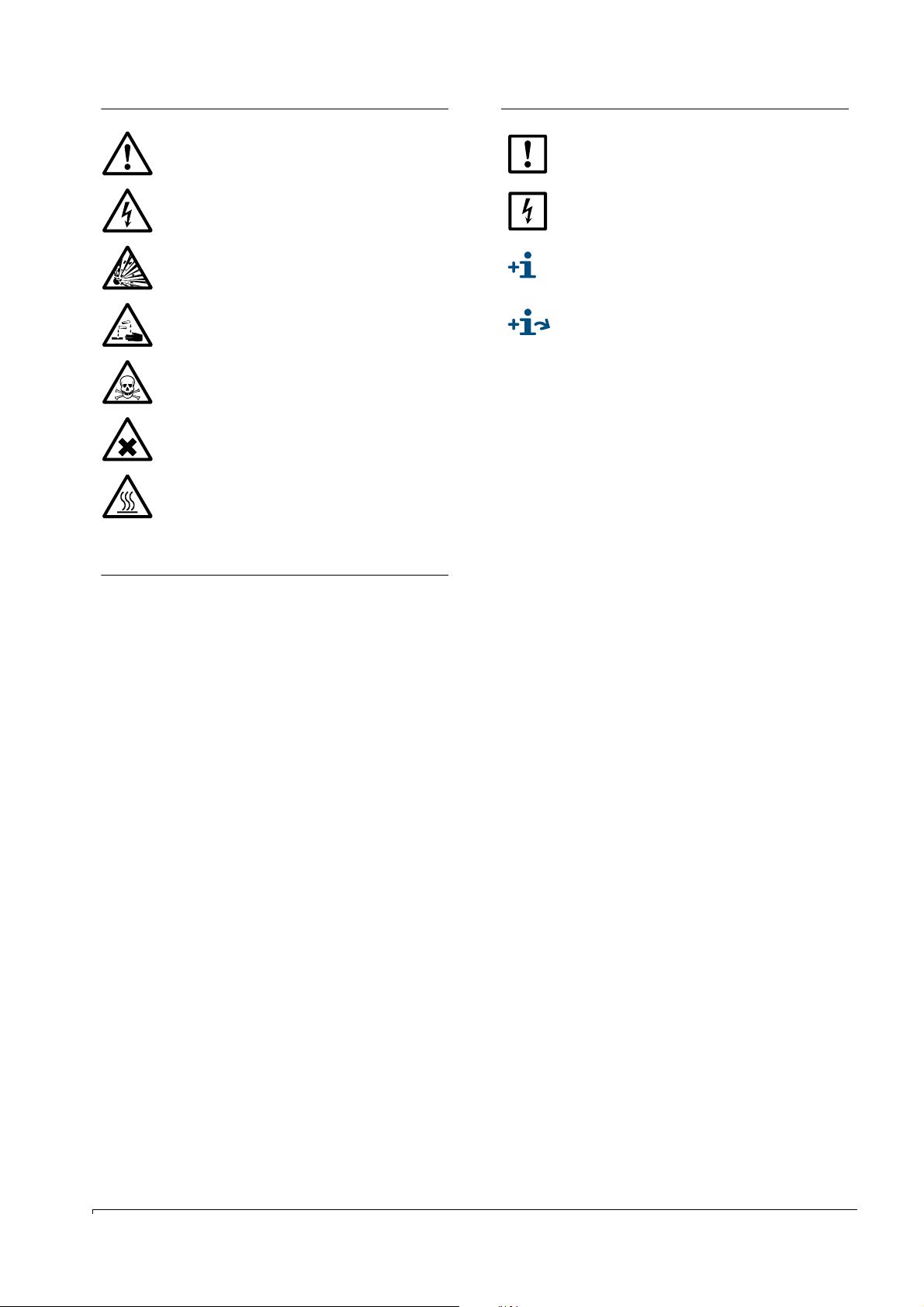
Warning Symbols
Information Symbols
Hazard (general)
Hazard by voltage
Hazard by explosive substances/mixtures
Hazard by corrosive substances
Hazard by toxic substances
Hazard by unhealthy substances
Hazard by high temperature or hot surface
Warning Levels / Signal Words
DANGER
Risk or hazardous situation which will result in severe personal
injury or death.
Important technical information for this device
Important information on electric or electronic functions
Supplementary information
Link to information at another place
WARNING
Risk or hazardous situation which could result in severe personal
injury or death.
CAUTION
Hazard or unsafe practice which could result in less severe or
minor injuries and/or property damage.
NOTICE
Hazard which could result in property damage.
MCS300P · Technical Information · 8013265 V1-2 · © SICK AG 3
Page 4

Contents
Contents
1 Important Information . . . . . . . . . . . . . . . . . . . . . . . . . . . . . . . . . . . . . . . . . . . . . . . 7
1.1 Validity. . . . . . . . . . . . . . . . . . . . . . . . . . . . . . . . . . . . . . . . . . . . . . . . . . . . . . . . . . . . . . . . . . . . . . 8
1.2 Responsibility of user. . . . . . . . . . . . . . . . . . . . . . . . . . . . . . . . . . . . . . . . . . . . . . . . . . . . . . . . . 8
1.2.1 Designated users . . . . . . . . . . . . . . . . . . . . . . . . . . . . . . . . . . . . . . . . . . . . . . . . . . . . . . . . . . 8
1.2.2 Special local conditions . . . . . . . . . . . . . . . . . . . . . . . . . . . . . . . . . . . . . . . . . . . . . . . . . . . . 8
2 Product Description. . . . . . . . . . . . . . . . . . . . . . . . . . . . . . . . . . . . . . . . . . . . . . . . . . . 9
2.1 Functional principle . . . . . . . . . . . . . . . . . . . . . . . . . . . . . . . . . . . . . . . . . . . . . . . . . . . . . . . . . 10
2.2 SOPAS ET (PC program). . . . . . . . . . . . . . . . . . . . . . . . . . . . . . . . . . . . . . . . . . . . . . . . . . . . . . 11
2.2.1 Modbus-TCP . . . . . . . . . . . . . . . . . . . . . . . . . . . . . . . . . . . . . . . . . . . . . . . . . . . . . . . . . . . . . 11
2.2.2 OPC (option) . . . . . . . . . . . . . . . . . . . . . . . . . . . . . . . . . . . . . . . . . . . . . . . . . . . . . . . . . . . . . 11
2.3 Circuit board. . . . . . . . . . . . . . . . . . . . . . . . . . . . . . . . . . . . . . . . . . . . . . . . . . . . . . . . . . . . . . . . 12
3Operation. . . . . . . . . . . . . . . . . . . . . . . . . . . . . . . . . . . . . . . . . . . . . . . . . . . . . . . . . . . . . . . 13
3.1 SOPAS ET (Description) . . . . . . . . . . . . . . . . . . . . . . . . . . . . . . . . . . . . . . . . . . . . . . . . . . . . . . 14
3.1.1 Changing the user level . . . . . . . . . . . . . . . . . . . . . . . . . . . . . . . . . . . . . . . . . . . . . . . . . . . 14
3.1.2 Grayed out fields - input not possible . . . . . . . . . . . . . . . . . . . . . . . . . . . . . . . . . . . . . . . 14
3.1.3 Using menus with assignments and calculations. . . . . . . . . . . . . . . . . . . . . . . . . . . . . 14
3.2 Menu tree (in SOPAS ET). . . . . . . . . . . . . . . . . . . . . . . . . . . . . . . . . . . . . . . . . . . . . . . . . . . . . 15
3.3 Measuring Screen. . . . . . . . . . . . . . . . . . . . . . . . . . . . . . . . . . . . . . . . . . . . . . . . . . . . . . . . . . . 17
3.3.1 Measuring Screen 1 .. x . . . . . . . . . . . . . . . . . . . . . . . . . . . . . . . . . . . . . . . . . . . . . . . . . . . 17
3.3.1.1 Scaling the Measuring Screen . . . . . . . . . . . . . . . . . . . . . . . . . . . . . . . . . . . . . . . . . . 19
3.4 Diagnosis . . . . . . . . . . . . . . . . . . . . . . . . . . . . . . . . . . . . . . . . . . . . . . . . . . . . . . . . . . . . . . . . . . 20
3.4.1 Control value . . . . . . . . . . . . . . . . . . . . . . . . . . . . . . . . . . . . . . . . . . . . . . . . . . . . . . . . . . . . . 20
3.4.1.1 Zero drift. . . . . . . . . . . . . . . . . . . . . . . . . . . . . . . . . . . . . . . . . . . . . . . . . . . . . . . . . . . . . . 20
3.4.1.2 Reference energy . . . . . . . . . . . . . . . . . . . . . . . . . . . . . . . . . . . . . . . . . . . . . . . . . . . . . . 20
3.4.1.3 Intensity . . . . . . . . . . . . . . . . . . . . . . . . . . . . . . . . . . . . . . . . . . . . . . . . . . . . . . . . . . . . . . 20
3.4.2 Sensor values . . . . . . . . . . . . . . . . . . . . . . . . . . . . . . . . . . . . . . . . . . . . . . . . . . . . . . . . . . . . 21
3.4.2.1 Temperatures . . . . . . . . . . . . . . . . . . . . . . . . . . . . . . . . . . . . . . . . . . . . . . . . . . . . . . . . . 21
3.4.2.2 Hardware . . . . . . . . . . . . . . . . . . . . . . . . . . . . . . . . . . . . . . . . . . . . . . . . . . . . . . . . . . . . . 21
3.4.3 Signals . . . . . . . . . . . . . . . . . . . . . . . . . . . . . . . . . . . . . . . . . . . . . . . . . . . . . . . . . . . . . . . . . . 22
3.4.3.1 Measuring signals . . . . . . . . . . . . . . . . . . . . . . . . . . . . . . . . . . . . . . . . . . . . . . . . . . . . . 22
3.4.3.2 Digital signals . . . . . . . . . . . . . . . . . . . . . . . . . . . . . . . . . . . . . . . . . . . . . . . . . . . . . . . . . 22
3.4.3.3 Analog signals. . . . . . . . . . . . . . . . . . . . . . . . . . . . . . . . . . . . . . . . . . . . . . . . . . . . . . . . . 22
3.4.3.4 Real values . . . . . . . . . . . . . . . . . . . . . . . . . . . . . . . . . . . . . . . . . . . . . . . . . . . . . . . . . . . 22
3.4.3.5 Integer and filtered values . . . . . . . . . . . . . . . . . . . . . . . . . . . . . . . . . . . . . . . . . . . . . . 22
3.4.4 Logbook . . . . . . . . . . . . . . . . . . . . . . . . . . . . . . . . . . . . . . . . . . . . . . . . . . . . . . . . . . . . . . . . . 23
3.4.5 System status . . . . . . . . . . . . . . . . . . . . . . . . . . . . . . . . . . . . . . . . . . . . . . . . . . . . . . . . . . . . 24
3.4.6 System information . . . . . . . . . . . . . . . . . . . . . . . . . . . . . . . . . . . . . . . . . . . . . . . . . . . . . . . 24
4 MCS300P · Technical Information · 8013265 V1-2 · © SICK AG
Page 5

Contents
3.5 Parameterization . . . . . . . . . . . . . . . . . . . . . . . . . . . . . . . . . . . . . . . . . . . . . . . . . . . . . . . . . . . . 25
3.5.1 Measuring components. . . . . . . . . . . . . . . . . . . . . . . . . . . . . . . . . . . . . . . . . . . . . . . . . . . . 25
3.5.1.1 Global definitions . . . . . . . . . . . . . . . . . . . . . . . . . . . . . . . . . . . . . . . . . . . . . . . . . . . . . . 25
3.5.1.2 Definition measuring components . . . . . . . . . . . . . . . . . . . . . . . . . . . . . . . . . . . . . . . 25
3.5.2 Measuring screen . . . . . . . . . . . . . . . . . . . . . . . . . . . . . . . . . . . . . . . . . . . . . . . . . . . . . . . . . 26
3.5.2.1 Measuring box . . . . . . . . . . . . . . . . . . . . . . . . . . . . . . . . . . . . . . . . . . . . . . . . . . . . . . . . . 27
3.5.2.2 Bargraph . . . . . . . . . . . . . . . . . . . . . . . . . . . . . . . . . . . . . . . . . . . . . . . . . . . . . . . . . . . . . . 27
3.5.2.3 Line writer. . . . . . . . . . . . . . . . . . . . . . . . . . . . . . . . . . . . . . . . . . . . . . . . . . . . . . . . . . . . . 28
3.5.3 I/O . . . . . . . . . . . . . . . . . . . . . . . . . . . . . . . . . . . . . . . . . . . . . . . . . . . . . . . . . . . . . . . . . . . . . . 29
3.5.3.1 Addressing system . . . . . . . . . . . . . . . . . . . . . . . . . . . . . . . . . . . . . . . . . . . . . . . . . . . . . 29
3.5.3.2 Hardware map . . . . . . . . . . . . . . . . . . . . . . . . . . . . . . . . . . . . . . . . . . . . . . . . . . . . . . . . . 30
3.5.3.3 Data . . . . . . . . . . . . . . . . . . . . . . . . . . . . . . . . . . . . . . . . . . . . . . . . . . . . . . . . . . . . . . . . . . 30
3.5.4 Variables and Functions . . . . . . . . . . . . . . . . . . . . . . . . . . . . . . . . . . . . . . . . . . . . . . . . . . . 32
3.5.4.1 Timer . . . . . . . . . . . . . . . . . . . . . . . . . . . . . . . . . . . . . . . . . . . . . . . . . . . . . . . . . . . . . . . . . 32
3.5.4.2 Cyclic trigger (CTi) . . . . . . . . . . . . . . . . . . . . . . . . . . . . . . . . . . . . . . . . . . . . . . . . . . . . . . 32
3.5.5 Formulas . . . . . . . . . . . . . . . . . . . . . . . . . . . . . . . . . . . . . . . . . . . . . . . . . . . . . . . . . . . . . . . . .35
3.5.6 Temperature control. . . . . . . . . . . . . . . . . . . . . . . . . . . . . . . . . . . . . . . . . . . . . . . . . . . . . . . 35
3.5.7 Logbook. . . . . . . . . . . . . . . . . . . . . . . . . . . . . . . . . . . . . . . . . . . . . . . . . . . . . . . . . . . . . . . . . . 35
3.5.8 Instrument display . . . . . . . . . . . . . . . . . . . . . . . . . . . . . . . . . . . . . . . . . . . . . . . . . . . . . . . . 36
3.5.9 System parameter . . . . . . . . . . . . . . . . . . . . . . . . . . . . . . . . . . . . . . . . . . . . . . . . . . . . . . . . 36
3.5.10 Modbus . . . . . . . . . . . . . . . . . . . . . . . . . . . . . . . . . . . . . . . . . . . . . . . . . . . . . . . . . . . . . . . . . .37
3.6 Adjustment . . . . . . . . . . . . . . . . . . . . . . . . . . . . . . . . . . . . . . . . . . . . . . . . . . . . . . . . . . . . . . . . .38
3.6.1 Parameter . . . . . . . . . . . . . . . . . . . . . . . . . . . . . . . . . . . . . . . . . . . . . . . . . . . . . . . . . . . . . . . . 38
3.6.1.1 Concentration . . . . . . . . . . . . . . . . . . . . . . . . . . . . . . . . . . . . . . . . . . . . . . . . . . . . . . . . . 38
3.6.1.2 Adjustment factors . . . . . . . . . . . . . . . . . . . . . . . . . . . . . . . . . . . . . . . . . . . . . . . . . . . . . 38
3.6.1.3 Start times . . . . . . . . . . . . . . . . . . . . . . . . . . . . . . . . . . . . . . . . . . . . . . . . . . . . . . . . . . . . 38
3.6.2 Manual adjustment . . . . . . . . . . . . . . . . . . . . . . . . . . . . . . . . . . . . . . . . . . . . . . . . . . . . . . . 39
3.6.3 Automatic adjustment . . . . . . . . . . . . . . . . . . . . . . . . . . . . . . . . . . . . . . . . . . . . . . . . . . . . . 39
3.7 Maintenance. . . . . . . . . . . . . . . . . . . . . . . . . . . . . . . . . . . . . . . . . . . . . . . . . . . . . . . . . . . . . . . . 40
3.7.1 Tests . . . . . . . . . . . . . . . . . . . . . . . . . . . . . . . . . . . . . . . . . . . . . . . . . . . . . . . . . . . . . . . . . . . .40
3.7.2
Operating states . . . . . . . . . . . . . . . . . . . . . . . . . . . . . . . . . . . . . . . . . . . . . . . . . . . . . . . . . . 40
3.7.3 Hardware reset . . . . . . . . . . . . . . . . . . . . . . . . . . . . . . . . . . . . . . . . . . . . . . . . . . . . . . . . . . . 41
3.7.4 Reset messages . . . . . . . . . . . . . . . . . . . . . . . . . . . . . . . . . . . . . . . . . . . . . . . . . . . . . . . . . . 41
3.7.5 Service log . . . . . . . . . . . . . . . . . . . . . . . . . . . . . . . . . . . . . . . . . . . . . . . . . . . . . . . . . . . . . . . 41
3.8 Tags (identifiers) . . . . . . . . . . . . . . . . . . . . . . . . . . . . . . . . . . . . . . . . . . . . . . . . . . . . . . . . . . . . 42
MCS300P · Technical Information · 8013265 V1-2 · © SICK AG 5
Page 6

Contents
6 MCS300P · Technical Information · 8013265 V1-2 · © SICK AG
Page 7

Important Information
MCS300P
1 Important Information
Main hazards
Main instructions for operation
Own responsibility
Subject to change w ithout notice
MCS300P · Technical Information · 8013265 V1-2 · © SICK AG 7
Page 8

1.1 Validity
This Manual is valid for the MCS300P and MCS300P-Ex.
It is only valid in combination with the "Operating Instructions MCS300P" or
"Operating Instructions MCS300P-Ex".
1.2 Responsibility of user
1.2.1 Designated users
This Technical Information is aimed at qualified persons familiar with the MCS300P and
who, based on their device-specific training and knowledge of the device as well as knowledge of the relevant regulations, can assess the tasks given and recognize the dangers
involved.
1.2.2 Special local conditions
Follow all local laws, regulations and company-internal operating directives applicable at
the respective installation location of the equipment.
Important Information
8 MCS300P · Technical Information · 8013265 V1-2 · © SICK AG
Subject to change w ithout notice
Page 9

Product Description
MCS300P
2 Product Description
Functional principle
Characteristics
Subject to change w ithout notice
MCS300P · Technical Information · 8013265 V1-2 · © SICK AG 9
Page 10
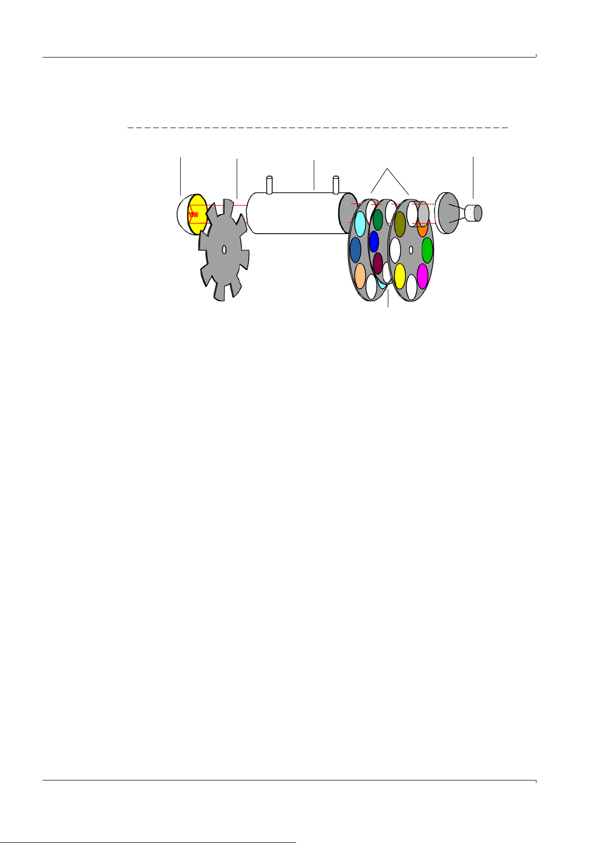
2.1 Functional principle
Source Chopper Cell Filter wheels with
measuring filters
Detector
Filter wheel with
adjustment standard
MCS300P is a non-dispersive process photometer.
Fig. 1 Beam path
Product Description
● Depending on the device type, the radiation source used is an IR or VIS radiator.
● The measuring beam goes through the sample cell and is specifically absorbed
depending on the sample gas composition.
● Interference and gas filters swiveled into the beam path on filter wheels select the
measurement wavelength.
● The detector receives the successive measurement and reference radiation.
– With the measuring filter swiveled in, the signal depends on the sample gas compo-
sition.
– With the reference filter swiveled in, a concentration-independent signal is gener-
ated.
By computation of both signals, the MCS300P determines the measured variable
"absorption” which is then, to a wide extent, independent from the changes of the optical characteristics of the photometer.
After correction of possible disturbance variables, the determined absorption is converted to the concentration value via the linearization function.
● As an option, a filter wheel with an internal adjustment standard is available which simulates a test with a test medium.
10 MCS300P · Technical Information · 8013265 V1-2 · © SICK AG
Subject to change w ithout notice
Page 11

Product Description
2.2 SOPAS ET (PC program)
SOPAS ET can be used to set the MCS300P parameters and provides access to the
MCS300P logbook.
SOPAS ET runs on an external PC connected via the Ethernet interface to the MCS300P
( MCS300P Operating Instructions).
2.2.1 Modbus-TCP
Modbus® is a communication standard for digital controls to connect a »Master« device
with several »Slave« devices. The Modbus protocol defines the communication commands
only but not their electronic transfer; therefore it can be used with different digital interfaces (for MCS300P: Ethernet).
Configuration: → p. 30, § 3.5.3.3
2.2.2 OPC (option)
OPC is a standardized software interface that allows to exchange data between different
applications.
The SICK OPC server (part of SOPAS ET) is required.
System bus: Ethernet.
Configuration: → p. 30, § 3.5.3.3
Subject to change w ithout notice
MCS300P · Technical Information · 8013265 V1-2 · © SICK AG 11
Page 12
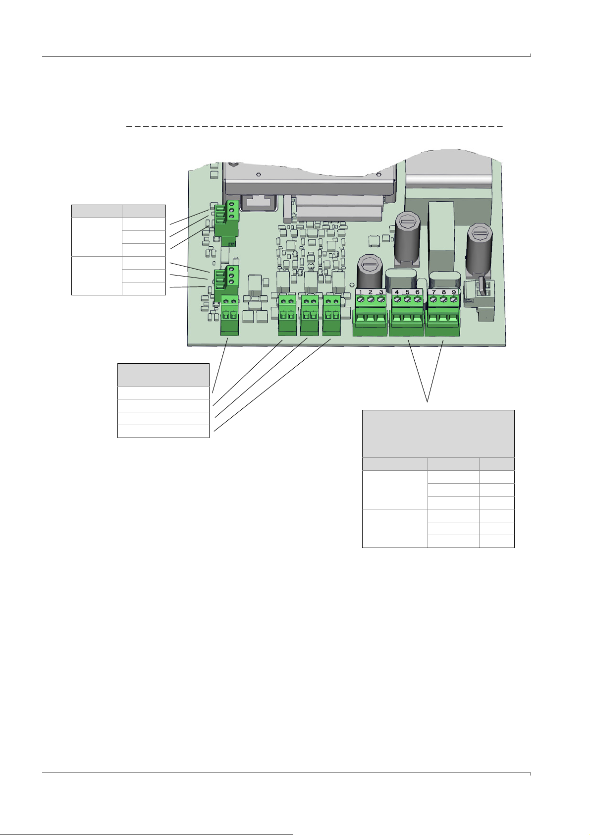
2.3 Circuit board
Pt100
Line: AWG26-15
Controller 2 limiter
Controller 1 limiter
Controller 2
Controller 1 (cell)
Heaters
Output voltage as mains voltage
Capacity: Max. 550 VA (per output)
Line: AWG24-12
Heater Line Pin
Heater 1
(cell)
L1 4
N5
PE 6
Heater 2 L1 7
N8
PE 9
CAN Line
CAN1
(internal)
ISOGND
LOW
HIGH
CAN2
External I/O
ISOGND
LOW
HIGH
Electrical connections on the circuit board in the sender unit
Fig. 2 Electrical connections in the sender unit
Product Description
12 MCS300P · Technical Information · 8013265 V1-2 · © SICK AG
Subject to change w ithout notice
Page 13

Operation
MCS300P
3 Operation
Configuration
Advanced operation
Adjustments
Subject to change w ithout notice
MCS300P · Technical Information · 8013265 V1-2 · © SICK AG 13
Page 14

3.1 SOPAS ET (Description)
SOPAS ET is on the CD-ROM enclosed with the MCS300P.
Operator menus and measured value displays are also available on an external PC via Ethernet for user comfort (with the engineering tool SOPAS ET).
The SICK Open Portal for Applications and Systems (SOPAS) is an engineering tool for communication with analyzers and sensors.
SOPAS is based on the following techniques:
● Device communication via Ethernet (TCP/IP).
● A common engineering tool for the various product lines.
● Universal device description file as the data source for all relevant device data and
parameters required for communication and display.
3.1.1 Changing the user level
In SOPAS ET
1 Click: Authorized Operator in the dialog window in SOPAS ET
2 Enter the password.
Operation
User level Password
Authorized operator HIDE
[1] Upper case mandatory
3.1.2 Grayed out fields - input not possible
[1]
Displays in grayed out fields cannot be changed.
3.1.3 Using menus with assignments and calculations
Example: Menu: MCS300P/Parameterization/I/O/Data/Digital outputs
Entry field Significance
Save Store current entries
Mark Create group
▸
Click "Mark" and then click the desired lines.
▸
To cancel "Mark":
Click "Mark" again and then click on an empty line.
Edit For editable menus: Call up the Settings menu for the line
▸
Click the desired line. Then click "Edit".
Show For non-editable menus: display settings for the line.
▸
Click the desired line. Then click "Show".
Copy Copy marked lines
Replace Insert copied lines before a marked line.
Next Call up the "Next function group".
(The bottom lines of the example depend on the menu)
Subject to change w ithout notice
14 MCS300P · Technical Information · 8013265 V1-2 · © SICK AG
Page 15

Operation
3.2 Menu tree (in SOPAS ET)
Menu Reference
Measuring screen → p. 17, §3.3
Measuring Screen xx
Diagnosis → p. 20, §3.4
Control values → p. 20, §3.4.1
Zero drift
Reference display
Intensity
Sensor values → p. 21, § 3.4.2
Temperatures
Hardware
Signals → p. 22, §3.4.3
Measuring signals
Digital signals
Analog signals
Real values
Integer and filtered values
Logbook → p. 23, §3.4.4
System status → p. 24, §3.4.5
System information → p. 24, §3.4.6
Parameterization → p. 25, §3.5
Measuring components → p. 25, §3.5.1
Global definitions
Definition measured value components
Measuring component xx
Measuring screen → p. 26, §3.5.2
Measured value xx
I/O → p. 29, §3.5.3
Hardware map
CAN Bus address 0..3 (N1 .. N2)
Data
OPC outputs (OPCOi)
Modbus outputs (MBOi)
Modbus inputs (MBIi)
Digital inputs (DIi)
Digital outputs (DOi)
Analog inputs (AIi)
Analog outputs (AOi)
Variables and Functions → p. 32, §3.5.4
Timer
Stop watches (SWi)
Cyclic trigger (CTi)
Limit values (LIi)
Real values (RVi)
Real constants (RCi)
Integer values (IVi)
Boolean values (BVi)
Filtered values (FVi)
Formulas → p. 35, §3.5.5
Temperature control → p. 35, §3.5.6
Logbook → p. 35, §3.5.7
Instrument display → p. 36, §3.5.8
System parameter → p. 36, §3.5.9
Subject to change w ithout notice
Modbus → p. 37, §3.5.10
Adjustment → p. 38, §3.6
Parameter → p. 38, §3.6.1
Concentration
Adjustment factors
MCS300P · Technical Information · 8013265 V1-2 · © SICK AG 15
Page 16

Menu Reference
Start times
Manual adjustment → p. 39, §3.6.2
Automatic adjustment → p. 39, §3.6.3
Maintenance → p. 40, §3.7
Tes ts → p. 40, §3.7.1
Digital inputs
Digital outputs
Analog inputs
Analog outputs
Operating states → p. 40, §3.7.2
Hardware Reset → p. 41, §3.7.3
Reset messages → p. 41, § 3.7.4
Service log → p. 41, §3.7.5
Operation
16 MCS300P · Technical Information · 8013265 V1-2 · © SICK AG
Subject to change w ithout notice
Page 17

Operation
Only the Measuring Screens are shown for which parameters have
been set.
▸
Double-click the desired Measuring Screen.
Component
Unit
Measured value
Component Measured value Unit
3.3 Measuring Screen
Menu: Measuring
Parameter settings of Measuring Screens: → p. 26, §3.5.2
Scaling of Measuring Screens: → p. 19, §3.3.1.1
3.3.1 Measuring Screen 1 .. x
Menu: Measuring/Measuring Screen 1 .. x
Depending on the parameters set, the Measuring Screen is shown as measuring box, bar
graph or line writer.
Measuring box
The measured values are shown numerically in the measuring box.
Bar graph
The measured values are shown as a graphic bar in the bar graph.
Subject to change w ithout notice
MCS300P · Technical Information · 8013265 V1-2 · © SICK AG 17
Page 18

Line writer and data storage
Measuring box
Line writer
The measured values that
have been activated are
shown (→ p. 19, § 3.3.1.1).
The line writer starts with the
representation only when the
display is called up for the
first time.
Changing the user level
deletes the history of the line
display.
The measured values are shown numerically as measuring box and as time diagram in the
line writer.
Operation
Data memory functions
▸
Start:
Start data storage.
The data for which parameters have been set are saved (independent from the graphic
representation) (→ p. 28, §3.5.2.3).
Max. 65536 entries per curve are saved in a file, afterwards a new file (with ascending
index) is automatically created.
▸
A dialog field to enter a target file (.txt) is displayed
The following is shown above the line diagram:
▸
Stop:
Stop recording.
▸
View:
View the recorded data.
A dialog field to select the file with the saved values is shown.
The following is then shown above the line diagram:
▸
Reset:
Delete all shown lines (no effect on data storage).
Subject to change w ithout notice
18 MCS300P · Technical Information · 8013265 V1-2 · © SICK AG
Page 19

Operation
▸
Font color (The colors of the line writer are predefined)
▸
Precision of Measuring Screen
Example:
-2: 123.45
-1: 1234.5
0
: 12345
1 : 123450
▸
Scale start value
▸
Scale end value
(line diagram: for y-axis)
▸
Display of lines active / not active
(for line writer)
3.3.1.1 Scaling the Measuring Screen
Touch the screen to display a scaling screen:
Subject to change w ithout notice
MCS300P · Technical Information · 8013265 V1-2 · © SICK AG 19
Page 20

3.4 Diagnosis
The zero drift since the last "Reset” of the zero
drift (e.g., during maintenance) is shown and
reset in this menu.
The zero drift is recalculated during each zero
adjustment and displayed in Absorption.
This value can be used for system diagnosis.
Typical cause: Decrease in lamp energy, contami-
nation of cell windows.
▸
Reset the zero drift
The current reference energy (in percent) is
shown and reset in this menu.
This value is monitored automatically. If the value
is below a limit value (default: 60%), the
MCS300P switches to the "Maintenance request”
classification.
Typical cause: Contamination of the cell windows.
▸
Reset the reference energy
3.4.1 Control value
3.4.1.1 Zero drift
Menu: Diagnosis/Control values/Zero drift
3.4.1.2 Reference energy
Menu: Diagnosis/Control values/Reference energy
Operation
3.4.1.3 Intensity
Menu: Diagnosis/Control values/Intensity
The intensities (energies) and amplification levels of the measured components are shown
in this menu.
Leave the evaluation of this information to SICK Customer Service.
20 MCS300P · Technical Information · 8013265 V1-2 · © SICK AG
Subject to change w ithout notice
Page 21

Operation
3.4.2 Sensor values
3.4.2.1 Temperatures
Menu: Diagnosis/Sensor values/Temperatures
Temperatures are shown in this menu.
3.4.2.2 Hardware
Menu: Diagnosis/Sensor values/Hardware
Operational parameters are shown in this menu.
Leave the evaluation of these parameters to SICK Customer Service.
Subject to change w ithout notice
MCS300P · Technical Information · 8013265 V1-2 · © SICK AG 21
Page 22

3.4.3 Signals
The current states of the digital signals (DIi,
DOi, limit values) are shown in this menu.
Digital values:
. = off (0)
I = on (1)
For limit values:
. = within the limit value
I = outside the limit value
The current values of the analog signals
(AIi, AOi) are shown in this menu
The current real values (RVi) are shown in
this menu.
The current integer values (IVi) and filtered
values (FVi) are shown in this menu.
3.4.3.1 Measuring signals
Menu: Diagnosis/Signals/Measuring signals
Measuring signals are shown in this menu.
Leave the evaluation of these signals to SICK Customer Service.
3.4.3.2 Digital signals
Parameter settings of the signals listed below: → p. 29, § 3.5.3 and the following
pages.
Menu: Diagnosis/Signals/Digital signals
Operation
3.4.3.3 Analog signals
Menu: Diagnosis/Signals/Analog signals
3.4.3.4 Real values
Menu: Diagnosis/Signals/Real values
3.4.3.5 Integer and filtered values
Menu: Diagnosis/Signals/Integer and filtered values
22 MCS300P · Technical Information · 8013265 V1-2 · © SICK AG
Subject to change w ithout notice
Page 23

Operation
3.4.4 Logbook
Menu: Diagnosis/Logbook
Max. number of entries: 6000.
(Representation: Uncompressed data storage)
Designation Remark
Fill level of logbook in %.
When the characters are red: The logbook is full.
Warning mode: Further entries are not accepted.
Circular buffer mode: Oldest entries are overwritten.
Data storage:
Symbol not crossed out: Compressed.
Symbol crossed out: Uncompressed.
Significance and default: → p. 35, §3.5.7
Circular buffer mode
Warning mode
Significance and default: → p. 35, §3.5.7
Entries Number of entries of selected filter.
Filter for messages Only the filtered messages are shown.
- Failure (active)
- Failure (all)
- Maintenance request (active)
- Maintenance request (all)
- Uncertain (active)
- Uncertain (all)
- Others (active)
- Others (all)
- All active messages
- All messages
Delete all entries. Caution: All logbook entries in the MCS300P are deleted.
Export All entries selected via the filter ( further back in this Table) are saved on the
PC in C:\My Documents as .log file.
Format: CSV (comma-separated list). Can be read in EXCEL, for example.
Refresh To refresh the display: Click.
Up Scroll to older entries
Down Scroll to newer entries
Consecutive message number.
Red LED: Message still pending.
Green LED: Message no longer pending.
Device Activating element: System, measured value identifier (sample gas component),
subassembly, Evaluation module
[1]
Entries
Subject to change w ithout notice
MCS300P · Technical Information · 8013265 V1-2 · © SICK AG 23
Text Logbook message (error messages Operating Instructions MCS300P).
Number of times errors have occurred.
Significance and default value: (→ p. 35, § 3.5.7)
Page 24

Designation Remark
LEDs according to operator panel
Current sampling point
For sampling point switching:
Time remaining until sampling
point switching
Time remaining of current
sequence program
Name of current sequence program
Classification F = Failure
Date Start Format: yy-mm-dd
Time Start Format: hh:mm:ss
Date stop Format: yy-mm-dd
Time stop Format: hh:mm:ss
[1]Only for compressed data storage
3.4.5 System status
Menu: Diagnosis/System status
Operation
M = Maintenance request
C = Check
U = Uncertain
X = Extended message
For "Uncompressed": Occurrence of message.
For "Compressed": Last occurrence of message.
For "Uncompressed": Occurrence of message.
For "Compressed": Last occurrence of message.
For "Uncompressed": Clearing of message.
For "Compressed": Last clearing of message.
For "Uncompressed": Clearing of message.
For "Compressed": Last clearing of message.
3.4.6 System information
Menu: Diagnosis/System information
System information (e.g.: Serial number, software version, cell length, window material) is
shown in this menu.
24 MCS300P · Technical Information · 8013265 V1-2 · © SICK AG
Subject to change w ithout notice
Page 25

Operation
Value above/below alarm Alarm value [in calibrated unit]
3.5 Parameterization
3.5.1 Measuring components
3.5.1.1 Global definitions
Menu: Parameterization/Measuring components/Global definitions
Global system information (e.g.: number of filter wheels, number of activated components)
is shown in this menu.
3.5.1.2 Definition measuring components
Menu: Parameterization/Measuring components/Definition measuring components
The setting of the individual measuring components is shown in this menu.
The following settings can be changed:
Subject to change w ithout notice
MCS300P · Technical Information · 8013265 V1-2 · © SICK AG 25
Page 26

3.5.2 Measuring screen
Selection of desired Measuring Screen
No display of measured values
1 measuring box
4 measuring boxes
16 measuring boxes (example → p. 27, §3.5.2.1)
2 large, 8 small measuring boxes
6 bargraphs (example → p. 27, §3.5.2.2)
3 bars + 2 measuring boxes
3 bars + 8 measuring boxes
(hidden)
Selected Measuring Screen
After changes: Click "Save”
Line writer (example → p. 28, §3.5.2.3)
Menu: Parameterization/Measuring screen
8 Measuring Screens can be parameterized and displayed:
Double-click a Measuring Screen to open the screen to set the parameters for the Measuring Screen.
Operation
26 MCS300P · Technical Information · 8013265 V1-2 · © SICK AG
Subject to change w ithout notice
Page 27

Operation
Example: Measuring Screen 1 with
Layout III (16 measuring boxes)
▸
Enter the desired identifiers (tags ).
Tags MCS300P: → p. 42, §3.8
Scaling of measuring box: → p. 19, § 3.3.1.1
The Measuring Screen then has the following
appearance:
The component names and units come, for
example, from the factory settings (e.g., RVi),
from a filter source (e.g., FVi) or from the analyzer.
Example: Measuring Screen 1 with bargraph I (6 bars)
▸
Enter the desired identifiers (tags ).
Scaling of measuring box: → p. 19, §3.3.1.1
The Measuring Screen then has the following
appearance:
3.5.2.1 Measuring box
3.5.2.2 Bargraph
Subject to change w ithout notice
MCS300P · Technical Information · 8013265 V1-2 · © SICK AG 27
Page 28

3.5.2.3 Line writer
▸
Enter the desired identifiers (tags).
Scaling of measuring box: → p. 19, § 3.3.1.1
▸
Scaling of time axis
[Sec, Min or Hour]
Scaling of y-axis: → p. 19, §3.3.1.1
The Measuring Screen then has the following
appearance:
Measuring box
Line writer
Operation
28 MCS300P · Technical Information · 8013265 V1-2 · © SICK AG
Subject to change w ithout notice
Page 29

Operation
CAN bus gateway 1
Node N1
CAN bus address 0