

Page 1

Title Page
MCS100E
IR Analyzer
Commissioning
Operation
Maintenance
OPERATING INSTRUCTIONS
Page 2

Document Information
Described Product
Product name: MCS100E
Document ID
Title: Operating Instructions MCS100E
Part No.: 8009504
Version: YWA7/V3-1
Release: 2018-01
Publisher
SICK AG
Erwin-Sick-Str. 1 · D-79183 Waldkirch · Germany
Tel.: +49 7641 469-0
Fax: +49 7641 469-1149
E-mail: info.pa@sick.de
Trademarks
MS-DOS is a Microsoft Corporation trademark.
Other product names used in this document may also be
trademarks and are only used for identification purposes.
Original Documents
The English version 8009504 of this document is an original
document from SICK AG.
SICK AG assumes no liability for the correctness of an
unauthorized translation.
Contacts
Guarantee Information
Specified product characteristics and technical data do not serve
as guarantee declarations.
© SICK AG. All rights reserved.
2 MCS100E Operating Instructions 8009504/VYWA7/V3-1/2018-01 © SICK AG
Page 3
Warning Symbols
Information Symbols
Hazard (general)
Hazard by voltage
Hazard in potentially explosive atmospheres
Hazard by explosive substances/mixtures
Hazard by corrosive substances
Hazard by poisonous substances
Hazard by unhealthy substances
Hazard by high temperature or hot surface
Important technical information for this device
Important information on electric or electronic
functions
Supplementary information
Link to information at another place
Hazard for the environment/nature/organic life
Warning Levels / Signal Words
DANGER
Risk or hazardous situation which will result in severe personal
injury or death.
WARNING
Risk or hazardous situation which could result in severe personal
injury or death.
CAUTION
Hazard or unsafe practice which could result in less severe or
minor injuries and/or property damage.
NOTICE
Hazard which could result in property damage.
MCS100E Operating Instructions 8009504/VYWA7/V3-1/2018-01 © SICK AG 3
Page 4

Contents
Contents
1 Important information . . . . . . . . . . . . . . . . . . . . . . . . . . . . . . . . . . . . . . . . . . . . . . 11
1.1 Main hazards . . . . . . . . . . . . . . . . . . . . . . . . . . . . . . . . . . . . . . . . . . . . . . . . . . . . . . . . . . . . . . . 12
1.2 Intended use . . . . . . . . . . . . . . . . . . . . . . . . . . . . . . . . . . . . . . . . . . . . . . . . . . . . . . . . . . . . . . . 12
1.2.1 Purpose of the device . . . . . . . . . . . . . . . . . . . . . . . . . . . . . . . . . . . . . . . . . . . . . . . . . . . . . 12
1.2.2 Installation site . . . . . . . . . . . . . . . . . . . . . . . . . . . . . . . . . . . . . . . . . . . . . . . . . . . . . . . . . . . 12
1.3 Responsibility of user. . . . . . . . . . . . . . . . . . . . . . . . . . . . . . . . . . . . . . . . . . . . . . . . . . . . . . . . 13
1.4 Additional documentation/information . . . . . . . . . . . . . . . . . . . . . . . . . . . . . . . . . . . . . . . . 13
2 Product description . . . . . . . . . . . . . . . . . . . . . . . . . . . . . . . . . . . . . . . . . . . . . . . . . . 15
2.1 Product identification. . . . . . . . . . . . . . . . . . . . . . . . . . . . . . . . . . . . . . . . . . . . . . . . . . . . . . . . 16
2.2 Description . . . . . . . . . . . . . . . . . . . . . . . . . . . . . . . . . . . . . . . . . . . . . . . . . . . . . . . . . . . . . . . . . 16
2.2.1 Design. . . . . . . . . . . . . . . . . . . . . . . . . . . . . . . . . . . . . . . . . . . . . . . . . . . . . . . . . . . . . . . . . . . 17
2.2.2 Measuring principle . . . . . . . . . . . . . . . . . . . . . . . . . . . . . . . . . . . . . . . . . . . . . . . . . . . . . . . 18
2.2.2.1 Correction of spectral interferences . . . . . . . . . . . . . . . . . . . . . . . . . . . . . . . . . . . . . 18
2.2.3 Thermostatic control . . . . . . . . . . . . . . . . . . . . . . . . . . . . . . . . . . . . . . . . . . . . . . . . . . . . . . 18
2.2.4 Cell. . . . . . . . . . . . . . . . . . . . . . . . . . . . . . . . . . . . . . . . . . . . . . . . . . . . . . . . . . . . . . . . . . . . . . 18
2.2.5 Flow meter . . . . . . . . . . . . . . . . . . . . . . . . . . . . . . . . . . . . . . . . . . . . . . . . . . . . . . . . . . . . . . . 18
2.2.6 O
2.2.7 Barometric pressure compensation (option) . . . . . . . . . . . . . . . . . . . . . . . . . . . . . . . . . 19
2.2.8 Interfaces . . . . . . . . . . . . . . . . . . . . . . . . . . . . . . . . . . . . . . . . . . . . . . . . . . . . . . . . . . . . . . . . 19
2.3 Data storage. . . . . . . . . . . . . . . . . . . . . . . . . . . . . . . . . . . . . . . . . . . . . . . . . . . . . . . . . . . . . . . . 20
2.4 Remote control . . . . . . . . . . . . . . . . . . . . . . . . . . . . . . . . . . . . . . . . . . . . . . . . . . . . . . . . . . . . . 20
2.5 Data transmission. . . . . . . . . . . . . . . . . . . . . . . . . . . . . . . . . . . . . . . . . . . . . . . . . . . . . . . . . . . 20
2.5.1 Data transmission with MCS100E program. . . . . . . . . . . . . . . . . . . . . . . . . . . . . . . . . . 20
2.5.2 File transfer with modem . . . . . . . . . . . . . . . . . . . . . . . . . . . . . . . . . . . . . . . . . . . . . . . . . . 20
2.6 Communication protocol . . . . . . . . . . . . . . . . . . . . . . . . . . . . . . . . . . . . . . . . . . . . . . . . . . . . . 20
2.7 QAL3 (DIN EN 14181) . . . . . . . . . . . . . . . . . . . . . . . . . . . . . . . . . . . . . . . . . . . . . . . . . . . . . . . 21
2.7.1 Evaluation of zero and reference point data . . . . . . . . . . . . . . . . . . . . . . . . . . . . . . . . . 21
2.7.2 Use of the calibration filter option . . . . . . . . . . . . . . . . . . . . . . . . . . . . . . . . . . . . . . . . . . 21
sensor (option) . . . . . . . . . . . . . . . . . . . . . . . . . . . . . . . . . . . . . . . . . . . . . . . . . . . . . . . . 19
2
4 MCS100E Operating Instructions 8009504/V YWA7/V3-1/2018-01 © SICK AG
Page 5

Contents
3 Installation . . . . . . . . . . . . . . . . . . . . . . . . . . . . . . . . . . . . . . . . . . . . . . . . . . . . . . . . . . . . . 23
3.1 Transport . . . . . . . . . . . . . . . . . . . . . . . . . . . . . . . . . . . . . . . . . . . . . . . . . . . . . . . . . . . . . . . . . . . 24
3.2 Installation and initial commissioning . . . . . . . . . . . . . . . . . . . . . . . . . . . . . . . . . . . . . . . . .24
3.2.1 Preparing the place of installation . . . . . . . . . . . . . . . . . . . . . . . . . . . . . . . . . . . . . . . . . . 24
3.2.2 Mechanical installation . . . . . . . . . . . . . . . . . . . . . . . . . . . . . . . . . . . . . . . . . . . . . . . . . . . . 24
3.2.2.1 Sample gas connections . . . . . . . . . . . . . . . . . . . . . . . . . . . . . . . . . . . . . . . . . . . . . . . .24
3.2.3 Interfaces . . . . . . . . . . . . . . . . . . . . . . . . . . . . . . . . . . . . . . . . . . . . . . . . . . . . . . . . . . . . . . . .26
3.2.3.1 Optical interfaces . . . . . . . . . . . . . . . . . . . . . . . . . . . . . . . . . . . . . . . . . . . . . . . . . . . . . . 26
3.2.3.2 Electric serial and parallel interface (option) . . . . . . . . . . . . . . . . . . . . . . . . . . . . . .28
3.2.3.3 Electric serial and Ethernet interface (option) . . . . . . . . . . . . . . . . . . . . . . . . . . . . .28
3.3 Remote control. . . . . . . . . . . . . . . . . . . . . . . . . . . . . . . . . . . . . . . . . . . . . . . . . . . . . . . . . . . . . . 29
3.3.1 Ethernet with TINY program . . . . . . . . . . . . . . . . . . . . . . . . . . . . . . . . . . . . . . . . . . . . . . . . 29
3.3.1.1 Connection on MCS100E side . . . . . . . . . . . . . . . . . . . . . . . . . . . . . . . . . . . . . . . . . . . 29
3.3.1.2 Connection on PC side. . . . . . . . . . . . . . . . . . . . . . . . . . . . . . . . . . . . . . . . . . . . . . . . . .29
3.3.1.3 Program start on MCS100E side. . . . . . . . . . . . . . . . . . . . . . . . . . . . . . . . . . . . . . . . . 29
3.3.1.4 Program start on PC side . . . . . . . . . . . . . . . . . . . . . . . . . . . . . . . . . . . . . . . . . . . . . . . 30
3.3.1.5 Special characters, e.g. on a German keyboard . . . . . . . . . . . . . . . . . . . . . . . . . . .30
3.3.2 Modem with the NetOP program . . . . . . . . . . . . . . . . . . . . . . . . . . . . . . . . . . . . . . . . . . . . 31
3.3.2.1 Connection on MCS100E side . . . . . . . . . . . . . . . . . . . . . . . . . . . . . . . . . . . . . . . . . . . 31
3.3.2.2 Connection on PC side. . . . . . . . . . . . . . . . . . . . . . . . . . . . . . . . . . . . . . . . . . . . . . . . . .31
3.3.2.3 Program start on MCS100E side. . . . . . . . . . . . . . . . . . . . . . . . . . . . . . . . . . . . . . . . . 31
3.3.2.4 Program start on PC side . . . . . . . . . . . . . . . . . . . . . . . . . . . . . . . . . . . . . . . . . . . . . . . 32
3.3.2.5 Terminating the transfer . . . . . . . . . . . . . . . . . . . . . . . . . . . . . . . . . . . . . . . . . . . . . . . . 32
3.4 Data transfer to/from external PC. . . . . . . . . . . . . . . . . . . . . . . . . . . . . . . . . . . . . . . . . . . . .33
3.4.1 Data transfer via fiber optical cable . . . . . . . . . . . . . . . . . . . . . . . . . . . . . . . . . . . . . . . . . 33
3.4.2 File transfer via modem . . . . . . . . . . . . . . . . . . . . . . . . . . . . . . . . . . . . . . . . . . . . . . . . . . . 33
3.5 Modbus communication protocol . . . . . . . . . . . . . . . . . . . . . . . . . . . . . . . . . . . . . . . . . . . . . 34
3.6 Hardware requirements for external PC . . . . . . . . . . . . . . . . . . . . . . . . . . . . . . . . . . . . . . . .34
3.7 Hardware requirements for printer . . . . . . . . . . . . . . . . . . . . . . . . . . . . . . . . . . . . . . . . . . . .34
3.8 Electrical installation. . . . . . . . . . . . . . . . . . . . . . . . . . . . . . . . . . . . . . . . . . . . . . . . . . . . . . . . . 35
3.8.1 Power voltage adjustment . . . . . . . . . . . . . . . . . . . . . . . . . . . . . . . . . . . . . . . . . . . . . . . . . 35
3.8.1.1 Adjusting the bridge for power voltage . . . . . . . . . . . . . . . . . . . . . . . . . . . . . . . . . . . 35
3.8.1.2 Power fuses . . . . . . . . . . . . . . . . . . . . . . . . . . . . . . . . . . . . . . . . . . . . . . . . . . . . . . . . . . . 36
4 Commissioning. . . . . . . . . . . . . . . . . . . . . . . . . . . . . . . . . . . . . . . . . . . . . . . . . . . . . . . . 37
4.1 Commissioning. . . . . . . . . . . . . . . . . . . . . . . . . . . . . . . . . . . . . . . . . . . . . . . . . . . . . . . . . . . . . . 38
4.2 External keyboard . . . . . . . . . . . . . . . . . . . . . . . . . . . . . . . . . . . . . . . . . . . . . . . . . . . . . . . . . . . 39
4.2.1 Country-specific assignment of keys . . . . . . . . . . . . . . . . . . . . . . . . . . . . . . . . . . . . . . . . 39
4.3 Language selection of the MCS program. . . . . . . . . . . . . . . . . . . . . . . . . . . . . . . . . . . . . . .39
4.4 Display setup . . . . . . . . . . . . . . . . . . . . . . . . . . . . . . . . . . . . . . . . . . . . . . . . . . . . . . . . . . . . . . . 39
MCS100E Operating Instructions 8009504/VYWA7/V3-1/2018-01 © SICK AG 5
Page 6

Contents
5Operation. . . . . . . . . . . . . . . . . . . . . . . . . . . . . . . . . . . . . . . . . . . . . . . . . . . . . . . . . . . . . . . 41
5.1 User interface . . . . . . . . . . . . . . . . . . . . . . . . . . . . . . . . . . . . . . . . . . . . . . . . . . . . . . . . . . . . . . 42
5.1.1 Significance of keys. . . . . . . . . . . . . . . . . . . . . . . . . . . . . . . . . . . . . . . . . . . . . . . . . . . . . . . 42
5.1.1.1 Entering alphanumerical characters . . . . . . . . . . . . . . . . . . . . . . . . . . . . . . . . . . . . . 43
5.2 Data and program storage . . . . . . . . . . . . . . . . . . . . . . . . . . . . . . . . . . . . . . . . . . . . . . . . . . . 44
5.2.1 Structure of directories . . . . . . . . . . . . . . . . . . . . . . . . . . . . . . . . . . . . . . . . . . . . . . . . . . . . 44
5.2.2 Data files . . . . . . . . . . . . . . . . . . . . . . . . . . . . . . . . . . . . . . . . . . . . . . . . . . . . . . . . . . . . . . . . 44
5.2.3 Program files . . . . . . . . . . . . . . . . . . . . . . . . . . . . . . . . . . . . . . . . . . . . . . . . . . . . . . . . . . . . . 44
5.3 Starting the measurement program . . . . . . . . . . . . . . . . . . . . . . . . . . . . . . . . . . . . . . . . . . . 45
5.3.1 Automatic start . . . . . . . . . . . . . . . . . . . . . . . . . . . . . . . . . . . . . . . . . . . . . . . . . . . . . . . . . . . 45
5.3.2 Starting from the DOS level . . . . . . . . . . . . . . . . . . . . . . . . . . . . . . . . . . . . . . . . . . . . . . . . 45
5.3.3 Aborting the start . . . . . . . . . . . . . . . . . . . . . . . . . . . . . . . . . . . . . . . . . . . . . . . . . . . . . . . . . 45
5.4 Stopping and starting measurement . . . . . . . . . . . . . . . . . . . . . . . . . . . . . . . . . . . . . . . . . . 46
5.4.1 STOP, START measurement. . . . . . . . . . . . . . . . . . . . . . . . . . . . . . . . . . . . . . . . . . . . . . . . 46
5.4.2 Quitting the measurement program . . . . . . . . . . . . . . . . . . . . . . . . . . . . . . . . . . . . . . . . 46
5.5 Status bars . . . . . . . . . . . . . . . . . . . . . . . . . . . . . . . . . . . . . . . . . . . . . . . . . . . . . . . . . . . . . . . . . 47
5.6 Using the menus . . . . . . . . . . . . . . . . . . . . . . . . . . . . . . . . . . . . . . . . . . . . . . . . . . . . . . . . . . . . 48
5.6.1 In Menu fields . . . . . . . . . . . . . . . . . . . . . . . . . . . . . . . . . . . . . . . . . . . . . . . . . . . . . . . . . . . . 48
5.6.2 In Entry menus . . . . . . . . . . . . . . . . . . . . . . . . . . . . . . . . . . . . . . . . . . . . . . . . . . . . . . . . . . . 48
5.6.3 In file selection lists. . . . . . . . . . . . . . . . . . . . . . . . . . . . . . . . . . . . . . . . . . . . . . . . . . . . . . . 48
5.6.4 Safety prompts . . . . . . . . . . . . . . . . . . . . . . . . . . . . . . . . . . . . . . . . . . . . . . . . . . . . . . . . . . . 49
6 MCS100E Operating Instructions 8009504/V YWA7/V3-1/2018-01 © SICK AG
Page 7

Contents
5.7 Menus. . . . . . . . . . . . . . . . . . . . . . . . . . . . . . . . . . . . . . . . . . . . . . . . . . . . . . . . . . . . . . . . . . . . . .50
5.7.1 Main menu . . . . . . . . . . . . . . . . . . . . . . . . . . . . . . . . . . . . . . . . . . . . . . . . . . . . . . . . . . . . . . . 50
5.7.2 Specialist: System edit . . . . . . . . . . . . . . . . . . . . . . . . . . . . . . . . . . . . . . . . . . . . . . . . . . . . 50
5.7.3 Specialist: Utilities . . . . . . . . . . . . . . . . . . . . . . . . . . . . . . . . . . . . . . . . . . . . . . . . . . . . . . . . 50
5.7.4 Specialist: Utilities: Service: Environment configuration . . . . . . . . . . . . . . . . . . . . . . . 51
5.7.5 Display graphic . . . . . . . . . . . . . . . . . . . . . . . . . . . . . . . . . . . . . . . . . . . . . . . . . . . . . . . . . . . 52
5.7.5.1 Graphic output: Time history . . . . . . . . . . . . . . . . . . . . . . . . . . . . . . . . . . . . . . . . . . . .52
5.7.5.2 Graphic output: Bar graph . . . . . . . . . . . . . . . . . . . . . . . . . . . . . . . . . . . . . . . . . . . . . .54
5.7.5.3 Archive Data. . . . . . . . . . . . . . . . . . . . . . . . . . . . . . . . . . . . . . . . . . . . . . . . . . . . . . . . . . . 54
5.7.6 Diagnosis . . . . . . . . . . . . . . . . . . . . . . . . . . . . . . . . . . . . . . . . . . . . . . . . . . . . . . . . . . . . . . . .55
5.7.7 Messages . . . . . . . . . . . . . . . . . . . . . . . . . . . . . . . . . . . . . . . . . . . . . . . . . . . . . . . . . . . . . . . .56
5.7.8 Print (On/Off) . . . . . . . . . . . . . . . . . . . . . . . . . . . . . . . . . . . . . . . . . . . . . . . . . . . . . . . . . . . . . 57
5.7.8.1 Print on-line (On/Off) . . . . . . . . . . . . . . . . . . . . . . . . . . . . . . . . . . . . . . . . . . . . . . . . . . . 57
5.7.8.2 Print Archive (Name) . . . . . . . . . . . . . . . . . . . . . . . . . . . . . . . . . . . . . . . . . . . . . . . . . . . 58
5.7.8.3 Start and end. . . . . . . . . . . . . . . . . . . . . . . . . . . . . . . . . . . . . . . . . . . . . . . . . . . . . . . . . . 58
5.7.8.4 Protocol Definition . . . . . . . . . . . . . . . . . . . . . . . . . . . . . . . . . . . . . . . . . . . . . . . . . . . . . 58
5.7.8.5 Protocol Start. . . . . . . . . . . . . . . . . . . . . . . . . . . . . . . . . . . . . . . . . . . . . . . . . . . . . . . . . . 59
5.7.8.6 Print diagnosis. . . . . . . . . . . . . . . . . . . . . . . . . . . . . . . . . . . . . . . . . . . . . . . . . . . . . . . . . 60
5.7.8.7 Print Messages . . . . . . . . . . . . . . . . . . . . . . . . . . . . . . . . . . . . . . . . . . . . . . . . . . . . . . . . 60
5.7.8.8 Print System data . . . . . . . . . . . . . . . . . . . . . . . . . . . . . . . . . . . . . . . . . . . . . . . . . . . . . . 60
5.7.9 Configuration . . . . . . . . . . . . . . . . . . . . . . . . . . . . . . . . . . . . . . . . . . . . . . . . . . . . . . . . . . . . . 61
5.7.9.1 Password for the configuration level . . . . . . . . . . . . . . . . . . . . . . . . . . . . . . . . . . . . . 61
5.7.9.2 Signal output . . . . . . . . . . . . . . . . . . . . . . . . . . . . . . . . . . . . . . . . . . . . . . . . . . . . . . . . . . 61
5.7.9.3 Graphic output. . . . . . . . . . . . . . . . . . . . . . . . . . . . . . . . . . . . . . . . . . . . . . . . . . . . . . . . . 62
5.7.9.4 Messages and corresp. relays . . . . . . . . . . . . . . . . . . . . . . . . . . . . . . . . . . . . . . . . . . . 62
5.7.9.5 Calibration gases . . . . . . . . . . . . . . . . . . . . . . . . . . . . . . . . . . . . . . . . . . . . . . . . . . . . . . 63
5.7.9.6 Zero/Calib/Purge programs . . . . . . . . . . . . . . . . . . . . . . . . . . . . . . . . . . . . . . . . . . . . . 65
5.7.9.7 Sample switching . . . . . . . . . . . . . . . . . . . . . . . . . . . . . . . . . . . . . . . . . . . . . . . . . . . . . . 66
5.7.10 Specialist menus. . . . . . . . . . . . . . . . . . . . . . . . . . . . . . . . . . . . . . . . . . . . . . . . . . . . . . . . . . 67
5.7.10.1 Password for the specialist level. . . . . . . . . . . . . . . . . . . . . . . . . . . . . . . . . . . . . . . . . 67
5.7.11 System edit (Name) . . . . . . . . . . . . . . . . . . . . . . . . . . . . . . . . . . . . . . . . . . . . . . . . . . . . . . . 68
5.7.11.1 Signal output . . . . . . . . . . . . . . . . . . . . . . . . . . . . . . . . . . . . . . . . . . . . . . . . . . . . . . . . . . 68
5.7.11.2 Graphic output
. . . . . . . . . . . . . . . . . . . . . . . . . . . . . . . . . . . . . . . . . . . . . . . . . . . . . . . . . 69
5.7.11.3 Messages and corresp. relays . . . . . . . . . . . . . . . . . . . . . . . . . . . . . . . . . . . . . . . . . . . 69
5.7.11.4 Calibration data. . . . . . . . . . . . . . . . . . . . . . . . . . . . . . . . . . . . . . . . . . . . . . . . . . . . . . . . 70
5.7.11.5 Zero/Calib/Purge programs/other programs. . . . . . . . . . . . . . . . . . . . . . . . . . . . . . 73
5.7.11.6 Sample switching . . . . . . . . . . . . . . . . . . . . . . . . . . . . . . . . . . . . . . . . . . . . . . . . . . . . . . 76
5.7.11.7 Results . . . . . . . . . . . . . . . . . . . . . . . . . . . . . . . . . . . . . . . . . . . . . . . . . . . . . . . . . . . . . . . 77
5.7.11.8 Definition of Components. . . . . . . . . . . . . . . . . . . . . . . . . . . . . . . . . . . . . . . . . . . . . . .79
5.7.11.9 Linearization tables . . . . . . . . . . . . . . . . . . . . . . . . . . . . . . . . . . . . . . . . . . . . . . . . . . . . 80
5.7.11.10 Interference table . . . . . . . . . . . . . . . . . . . . . . . . . . . . . . . . . . . . . . . . . . . . . . . . . . . . . . 81
5.7.11.11 Limit values . . . . . . . . . . . . . . . . . . . . . . . . . . . . . . . . . . . . . . . . . . . . . . . . . . . . . . . . . . . 82
5.7.11.12 Temperatures and Pressure . . . . . . . . . . . . . . . . . . . . . . . . . . . . . . . . . . . . . . . . . . . . .83
5.7.11.13 Protocol Definition . . . . . . . . . . . . . . . . . . . . . . . . . . . . . . . . . . . . . . . . . . . . . . . . . . . . . 85
5.7.11.14 Data storage and send to PC . . . . . . . . . . . . . . . . . . . . . . . . . . . . . . . . . . . . . . . . . . . . 86
5.7.11.15 Softkey menu definition . . . . . . . . . . . . . . . . . . . . . . . . . . . . . . . . . . . . . . . . . . . . . . . . 87
5.7.11.16 Mean square fit data . . . . . . . . . . . . . . . . . . . . . . . . . . . . . . . . . . . . . . . . . . . . . . . . . . . 88
5.7.11.17 Operator's Notebook . . . . . . . . . . . . . . . . . . . . . . . . . . . . . . . . . . . . . . . . . . . . . . . . . . . 88
5.7.12 System, select for editing . . . . . . . . . . . . . . . . . . . . . . . . . . . . . . . . . . . . . . . . . . . . . . . . . . 89
5.7.13 System, create for editing. . . . . . . . . . . . . . . . . . . . . . . . . . . . . . . . . . . . . . . . . . . . . . . . . . 89
5.7.14 System, activate for measurement. . . . . . . . . . . . . . . . . . . . . . . . . . . . . . . . . . . . . . . . . .89
5.7.15 Utilities . . . . . . . . . . . . . . . . . . . . . . . . . . . . . . . . . . . . . . . . . . . . . . . . . . . . . . . . . . . . . . . . . . 90
5.7.15.1 Show files . . . . . . . . . . . . . . . . . . . . . . . . . . . . . . . . . . . . . . . . . . . . . . . . . . . . . . . . . . . . . 90
MCS100E Operating Instructions 8009504/VYWA7/V3-1/2018-01 © SICK AG 7
Page 8

Contents
5.7.15.2 Copy files . . . . . . . . . . . . . . . . . . . . . . . . . . . . . . . . . . . . . . . . . . . . . . . . . . . . . . . . . . . . . 90
5.7.15.3 Erase files . . . . . . . . . . . . . . . . . . . . . . . . . . . . . . . . . . . . . . . . . . . . . . . . . . . . . . . . . . . . 90
5.7.15.4 Send files to an external PC . . . . . . . . . . . . . . . . . . . . . . . . . . . . . . . . . . . . . . . . . . . . 90
5.7.15.5 Receive files from PC . . . . . . . . . . . . . . . . . . . . . . . . . . . . . . . . . . . . . . . . . . . . . . . . . . 91
5.7.15.6 Files directory . . . . . . . . . . . . . . . . . . . . . . . . . . . . . . . . . . . . . . . . . . . . . . . . . . . . . . . . . 91
5.7.15.7 Service (TEST). . . . . . . . . . . . . . . . . . . . . . . . . . . . . . . . . . . . . . . . . . . . . . . . . . . . . . . . . 92
5.7.15.8 Display, digital status . . . . . . . . . . . . . . . . . . . . . . . . . . . . . . . . . . . . . . . . . . . . . . . . . . 97
6 Decommissioning . . . . . . . . . . . . . . . . . . . . . . . . . . . . . . . . . . . . . . . . . . . . . . . . . . . . 99
6.1 Switch off . . . . . . . . . . . . . . . . . . . . . . . . . . . . . . . . . . . . . . . . . . . . . . . . . . . . . . . . . . . . . . . . . 100
6.2 Disassembly . . . . . . . . . . . . . . . . . . . . . . . . . . . . . . . . . . . . . . . . . . . . . . . . . . . . . . . . . . . . . . . 100
6.3 Storage . . . . . . . . . . . . . . . . . . . . . . . . . . . . . . . . . . . . . . . . . . . . . . . . . . . . . . . . . . . . . . . . . . . 100
6.4 Disposal. . . . . . . . . . . . . . . . . . . . . . . . . . . . . . . . . . . . . . . . . . . . . . . . . . . . . . . . . . . . . . . . . . . 100
7 Maintenance . . . . . . . . . . . . . . . . . . . . . . . . . . . . . . . . . . . . . . . . . . . . . . . . . . . . . . . . . 101
7.1 Maintenance intervals . . . . . . . . . . . . . . . . . . . . . . . . . . . . . . . . . . . . . . . . . . . . . . . . . . . . . . 102
7.2 Visual check of the MCS100E . . . . . . . . . . . . . . . . . . . . . . . . . . . . . . . . . . . . . . . . . . . . . . . 103
7.3 Check sample gas flow . . . . . . . . . . . . . . . . . . . . . . . . . . . . . . . . . . . . . . . . . . . . . . . . . . . . . 103
7.4 Check/replace the filter pad in the fan of the analyzer . . . . . . . . . . . . . . . . . . . . . . . . . 103
7.5 Span gas feeding . . . . . . . . . . . . . . . . . . . . . . . . . . . . . . . . . . . . . . . . . . . . . . . . . . . . . . . . . . 104
7.6 Programming the Measurement Sequence (Overview) . . . . . . . . . . . . . . . . . . . . . . . . . 105
7.6.1 Concentration Determination . . . . . . . . . . . . . . . . . . . . . . . . . . . . . . . . . . . . . . . . . . . . . 106
7.6.2 Definition of Components and Calibrating a System . . . . . . . . . . . . . . . . . . . . . . . . . 107
7.6.3 Addresses and Assignment of the Input Variables. . . . . . . . . . . . . . . . . . . . . . . . . . . 108
7.7 Parameters at Program Start . . . . . . . . . . . . . . . . . . . . . . . . . . . . . . . . . . . . . . . . . . . . . . . . 109
7.8 Watchdogs . . . . . . . . . . . . . . . . . . . . . . . . . . . . . . . . . . . . . . . . . . . . . . . . . . . . . . . . . . . . . . . . 109
7.8.1 CPU watchdog . . . . . . . . . . . . . . . . . . . . . . . . . . . . . . . . . . . . . . . . . . . . . . . . . . . . . . . . . . . 109
7.8.2 Watchdog for Communication . . . . . . . . . . . . . . . . . . . . . . . . . . . . . . . . . . . . . . . . . . . . . 110
7.9 Load Program from external PC. . . . . . . . . . . . . . . . . . . . . . . . . . . . . . . . . . . . . . . . . . . . . . 111
8Troubleshooting . . . . . . . . . . . . . . . . . . . . . . . . . . . . . . . . . . . . . . . . . . . . . . . . . . . . . 113
8.1 Adjust the monitor . . . . . . . . . . . . . . . . . . . . . . . . . . . . . . . . . . . . . . . . . . . . . . . . . . . . . . . . . 114
8.2 Flow too low . . . . . . . . . . . . . . . . . . . . . . . . . . . . . . . . . . . . . . . . . . . . . . . . . . . . . . . . . . . . . . . 114
8.3 MCS100E becomes too hot (excess temperature) . . . . . . . . . . . . . . . . . . . . . . . . . . . . . 114
8.4 MCS100E does not start operation upon power-on . . . . . . . . . . . . . . . . . . . . . . . . . . . . 114
8.5 Excess temperature switch-off. . . . . . . . . . . . . . . . . . . . . . . . . . . . . . . . . . . . . . . . . . . . . . . 114
8.6 Cell and photometer are not heated properly . . . . . . . . . . . . . . . . . . . . . . . . . . . . . . . . . 114
8.7 No contact with printer/PC resp. I/O module boxes. . . . . . . . . . . . . . . . . . . . . . . . . . . . 115
8.8 Fuses, jumpers and LEDs . . . . . . . . . . . . . . . . . . . . . . . . . . . . . . . . . . . . . . . . . . . . . . . . . . . 115
8.8.1 Internal voltage control (LPM40) . . . . . . . . . . . . . . . . . . . . . . . . . . . . . . . . . . . . . . . . . . 116
8.8.2 Heating controller (LPM42) . . . . . . . . . . . . . . . . . . . . . . . . . . . . . . . . . . . . . . . . . . . . . . . 117
8.9 Error messages on the screen. . . . . . . . . . . . . . . . . . . . . . . . . . . . . . . . . . . . . . . . . . . . . . . 118
8.9.1 Message: CAUTION! MOD-IO boxes changed . . . . . . . . . . . . . . . . . . . . . . . . . . . . . . . . 118
8 MCS100E Operating Instructions 8009504/V YWA7/V3-1/2018-01 © SICK AG
Page 9

Contents
9 Utility programs and protocols . . . . . . . . . . . . . . . . . . . . . . . . . . . . . . . . . . .119
9.1 MCSCONF . . . . . . . . . . . . . . . . . . . . . . . . . . . . . . . . . . . . . . . . . . . . . . . . . . . . . . . . . . . . . . . . .120
9.1.1 Start of the configuration program . . . . . . . . . . . . . . . . . . . . . . . . . . . . . . . . . . . . . . . . .120
9.1.2 Terminating the configuration program . . . . . . . . . . . . . . . . . . . . . . . . . . . . . . . . . . . . .120
9.1.3 Menus . . . . . . . . . . . . . . . . . . . . . . . . . . . . . . . . . . . . . . . . . . . . . . . . . . . . . . . . . . . . . . . . . .121
9.1.3.1 Runtime Parameters . . . . . . . . . . . . . . . . . . . . . . . . . . . . . . . . . . . . . . . . . . . . . . . . . . 121
9.1.3.2 Text Mode . . . . . . . . . . . . . . . . . . . . . . . . . . . . . . . . . . . . . . . . . . . . . . . . . . . . . . . . . . . . 122
9.1.3.3 Graphics . . . . . . . . . . . . . . . . . . . . . . . . . . . . . . . . . . . . . . . . . . . . . . . . . . . . . . . . . . . . . 122
9.1.3.4 Directories and files . . . . . . . . . . . . . . . . . . . . . . . . . . . . . . . . . . . . . . . . . . . . . . . . . . . 123
9.2 ACQINIT . . . . . . . . . . . . . . . . . . . . . . . . . . . . . . . . . . . . . . . . . . . . . . . . . . . . . . . . . . . . . . . . . . .124
9.3 Modbus protocol . . . . . . . . . . . . . . . . . . . . . . . . . . . . . . . . . . . . . . . . . . . . . . . . . . . . . . . . . . . 126
10 Specifications . . . . . . . . . . . . . . . . . . . . . . . . . . . . . . . . . . . . . . . . . . . . . . . . . . . . . . . . 133
10.1 Conformity . . . . . . . . . . . . . . . . . . . . . . . . . . . . . . . . . . . . . . . . . . . . . . . . . . . . . . . . . . . . . . . . .134
10.1.1 Electrical protection . . . . . . . . . . . . . . . . . . . . . . . . . . . . . . . . . . . . . . . . . . . . . . . . . . . . . . 134
10.2 Technical Data . . . . . . . . . . . . . . . . . . . . . . . . . . . . . . . . . . . . . . . . . . . . . . . . . . . . . . . . . . . . .135
10.2.1 Dimension drawing. . . . . . . . . . . . . . . . . . . . . . . . . . . . . . . . . . . . . . . . . . . . . . . . . . . . . . . 135
10.2.2 Operating data. . . . . . . . . . . . . . . . . . . . . . . . . . . . . . . . . . . . . . . . . . . . . . . . . . . . . . . . . . .136
MCS100E Operating Instructions 8009504/VYWA7/V3-1/2018-01 © SICK AG 9
Page 10

Contents
10 MCS100E Operating Instructions 8009504/VYWA7/V3-1/2018-01 © SICK AG
Page 11

Important information
MCS100E
1 Important information
Main hazards
Main instructions for operation
Intended use
Own responsibility
Subject to change without notice
MCS100E Operating Instructions 8009504/VYWA7/V3-1/2018-01 © SICK AG 11
Page 12
1.1 Main hazards
Important safety information in abbreviated form.
Always observe the complete safety information (see cross-references).
WARNING: Noxious and irritating sample gas
When the sample gas contains noxious or irritating substances:
Channel sample gas off safely (→p. 24, §3.2.2.1)
WARNING: Danger to life/health risks caused by leaks in the gas path
If noxious gases are channeled into the MCS100E: A leak in the gas path can
create acute danger for persons.
Ensure suitable safety measures.
WARNING: Hazards by explosive or combustible gases
⊗ Do not use the MCS100E for measuring explosive or combustible gases
WARNING: Hazard in potentially explosive atmospheres
⊗ Do not use the MCS100E in potentially explosive atmospheres.
Important information
1.2 Intended use
1.2.1 Purpose of the device
The MCS100E measuring device is used for continuous and selective measurement of
emissions (e.g.: HCl, NH
3
The MCS100E is normally located in the SICK MCS100E system cabinets.
Application limitations
The MCS100E only measures the gas composition correctly for which it was calibrated
(
→ System Documentation). A change of the gas matrix can result in incorrect measured
values.
NOTICE: Risk of contamination of the gas path
If the sample gas does not have the composition for which the MCS100E was
designed (
1.2.2 Installation site
→ System Documentation):
Ensure that the MCS100E cannot draw in sample gas.
Flush the gas path of the MCS100E with inert gas.
The MCS100E gas analyzer is designed for operation in rooms or system cabinets.
, H2O, CO, SO2, NOx, O2) in the stack gases of incineration plants.
12 MCS100E Operating Instructions 8009504/VYWA7/V3-1/2018-01 © SICK AG
Subject to change without notice
Page 13

Important information
1.3 Responsibility of user
Designated users
The MCS100E may be operated by competent persons only who, based on their devicespecific training and knowledge of the device as well as knowledge of the relevant
regulations, can assess the tasks given and recognize the dangers involved.
The Specialist level of the MCS100E may be operated only by skilled technicians who,
based on their technical training and knowledge as well as knowledge of the relevant
regulations, can assess the tasks given and recognize the hazards involved.
Correct use
Use the MCS100E only as described in these Operating Instructions. The manufacturer
bears no responsibility for any other use.
Perform the specified maintenance work.
Do not remove, add or modify any components to or on the device unless described and
specified in the official manufacturer information. Otherwise
– the device could become dangerous
– the manufacturer’s warranty becomes void
Special local conditions
In addition to these Operating Instructions, follow all local laws, technical rules and
company-internal operating directives applicable at the respective installation site of
the equipment.
Retention of documents
These Operating Instructions and the System Documentation:
Must be available for reference.
Must be passed on to new owners.
1.4 Additional documentation/information
System documentation
Individualized versions of MCS100E with adapted internal or peripheral equipment exist.
For the relevant information, see the delivered separate documentation, for example:
• Operating Instructions of additional components
Pay attention to the supplied documents.
Subject to change without notice
MCS100E Operating Instructions 8009504/VYWA7/V3-1/2018-01 © SICK AG 13
Page 14

Important information
14 MCS100E Operating Instructions 8009504/VYWA7/V3-1/2018-01 © SICK AG
Subject to change without notice
Page 15

Product description
MCS100E
2 Product description
Product identification
Functional principle
Characteristics
Variants
Subject to change without notice
MCS100E Operating Instructions 8009504/VYWA7/V3-1/2018-01 © SICK AG 15
Page 16
2.1 Product identification
Product name: MCS100E
Manufacturer:
SICK AG · Rengoldshauser Str. 17A
88662 Überlingen · Germany
The type plate is located on the top of the right side of the housing.
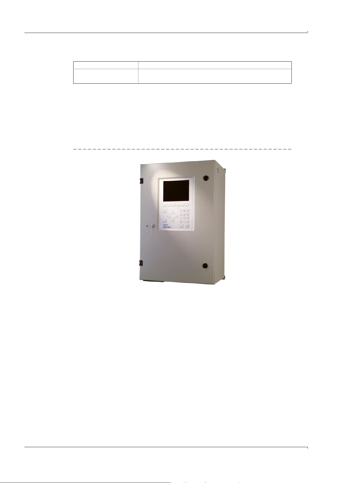
2.2 Description
The MCS100E measuring device is used for extractive continuous and selective
measurement of emissions (e.g.: HCl, NH
MCS100E can measure quasi-simultaneously up to 8 components (plus optionally O
max. 12 sample points.
Figure 1 MCS100E
, H2O, CO, SO2, NOx) of incineration plants.
3
Product description
) at
2
16 MCS100E Operating Instructions 8009504/VYWA7/V3-1/2018-01 © SICK AG
Subject to change without notice
Page 17
Product description
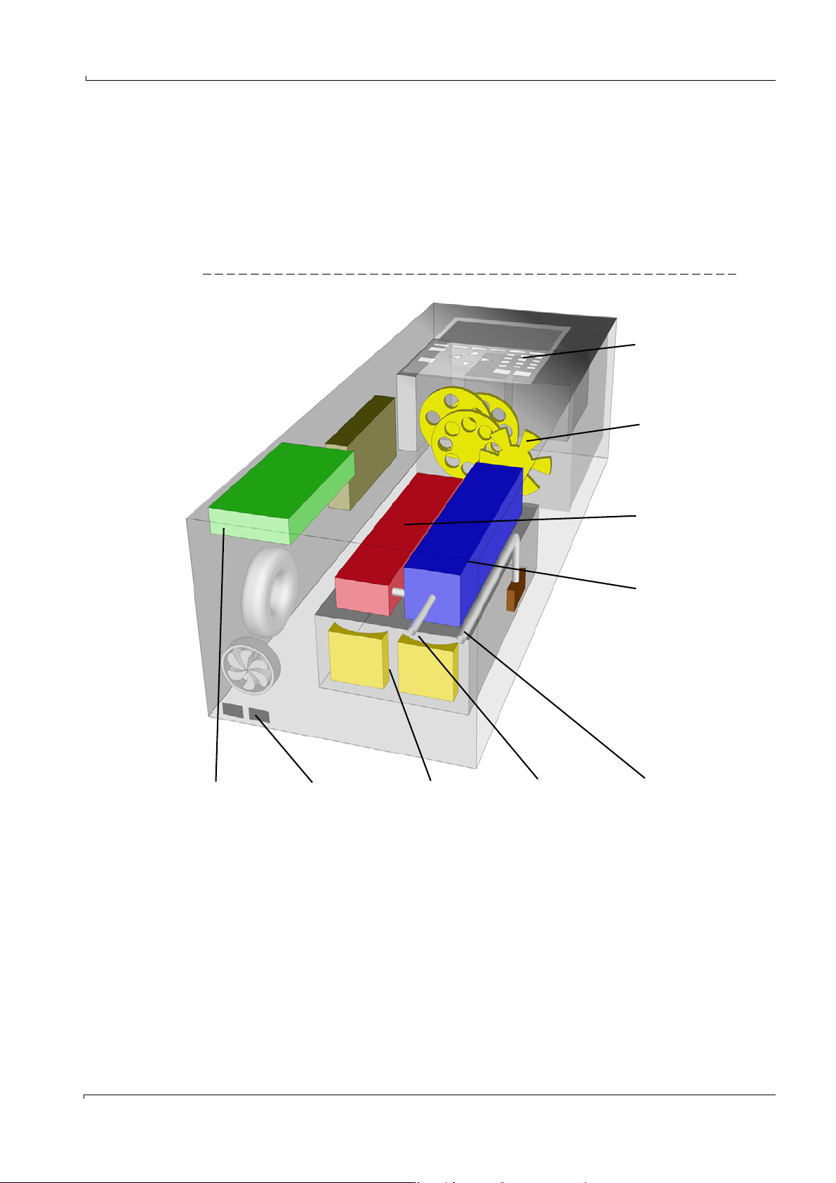
Computer
Flow meter
Photometer
User interface
Interfaces
Cell
Sample gas outlet
Sample gas inlet
O
2
sensor
(optional)
2.2.1 Design
MCS100E consists of the following main assemblies:
• Photometer with filter wheels (design dependent on application)
• Cell (optical path length dependent on application)
• Flow meter
•O
• Computer and electronics
Figure 2 MCS100E setup
sensor (optional)
2
Subject to change without notice
MCS100E Operating Instructions 8009504/VYWA7/V3-1/2018-01 © SICK AG 17
Page 18
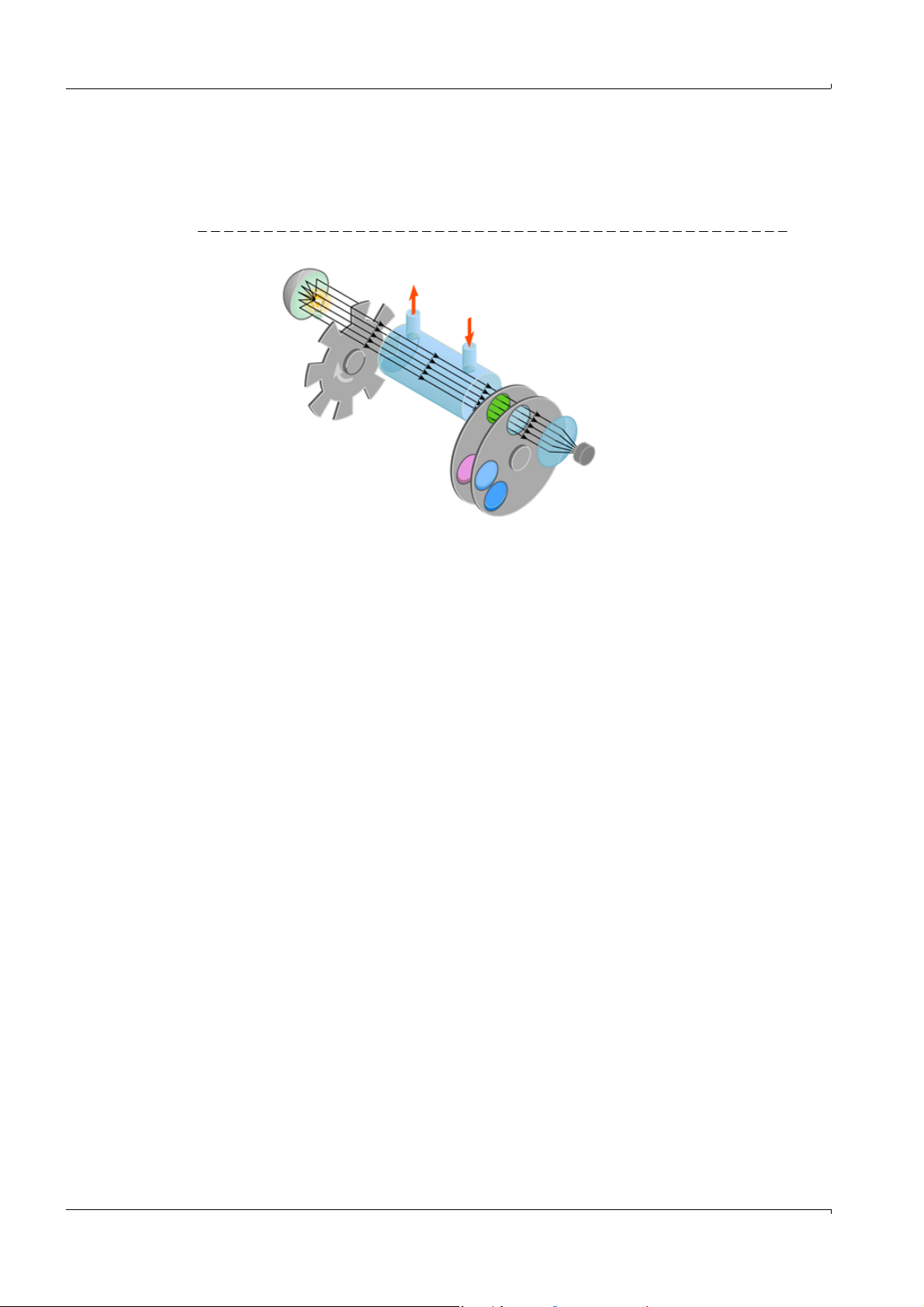
2.2.2 Measuring principle
Light source
Cell
Interference filter
Detector
MCS100E is a single-beam infrared photometer that works on the basis of the transmitted
light measuring technique applying the single-beam dual-wavelength method and the gas
filter correlation method.
Figure 3 Measuring principle
Product description
2.2.2.1
Correction of spectral interferences
In order to achieve greater measuring accuracy, interference sensitivities can be detected
and compensated (depending on application).
Additive (spectral superposition) and multiplicative (dilution effects) effects are considered.
Moreover, external digital and analog signals can be read in and processed (option).
2.2.3 Thermostatic control
MCS100E is equipped with a self-resetting thermal circuit breaker that protects the
instrument against thermal damage.
2.2.4 Cell
Sample gas filter
A sintered metal filter in the gas inlet of the cell serves as protective filter.
Beam path
The beam path corresponds to the principle of the White Cell with the beam being folded by
mirrors. The mirrors are mill-cut in the end plates. Thus the optical path length of the cell is
invariable (depending on the application).
Thermostatic control
The cell is thermostatic-controlled (temperature control
2.2.5 Flow meter
The flow meter functions on the resistance anemometer principle. It comprises two
temperature-dependent, heated resistors, one of which is positioned in the gas stream
begin measured while the other does not have gas flowing over it. The difference in the
resistances is a measure of the flow rate.
→
p. 83, §5.7.11.12).
Subject to change without notice
18 MCS100E Operating Instructions 8009504/VYWA7/V3-1/2018-01 © SICK AG
Page 19

Product description
2.2.6 O
sensor (option)
2
O2 measurement is carried out by means of a circonium dioxide sensor.
The sample gas flows past the O
sensor, the gas exchange inside the sensor takes place
2
by turbulence. Ambient air which reaches the cell by diffusion is used as reference gas.
2.2.7 Barometric pressure compensation (option)
Barometric pressure compensation for the MCS100E is available as an option.
2.2.8 Interfaces
Fiber optics interfaces
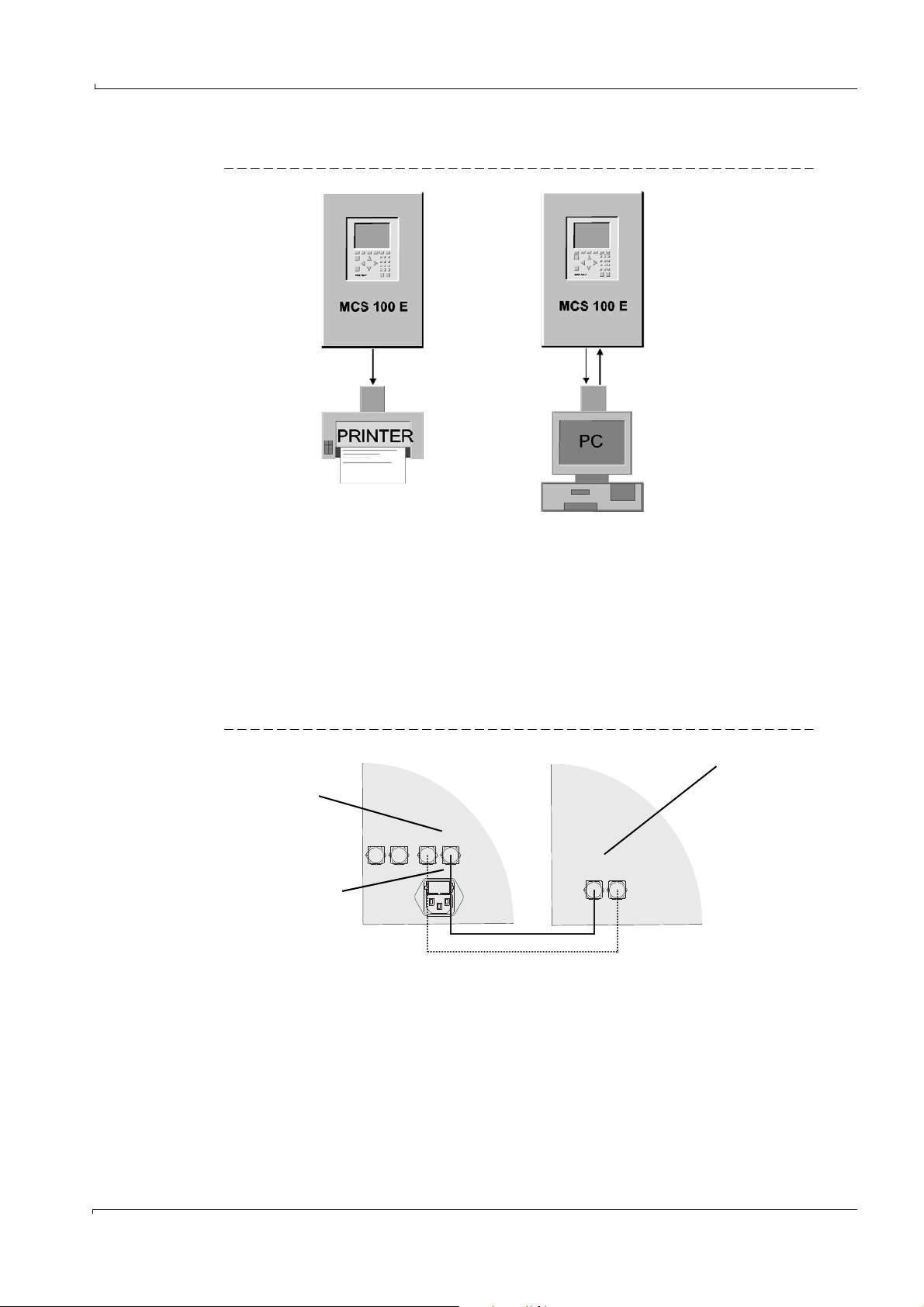
• 2 optical interfaces (fiber optics) for connection of:
– I/O module boxes (containing the digital and analog interfaces) or HC8X heating
controller (
–Printer or PC (
→
p. 26)
→
p. 27)
Electrical interfaces (option)
• 1 serial and 1 parallel interface for connection of:
–PC or MODEM and printer (
→
p. 28, §3.2.3.2)
OR
• 1 serial and 1 Ethernet interface for connection of
–PC and Ethernet (
→
p. 28, §3.2.3.3)
Subject to change without notice
MCS100E Operating Instructions 8009504/VYWA7/V3-1/2018-01 © SICK AG 19
Page 20

2.3 Data storage
• Storage of measured values (→p. 44, §5.2).
• Storage of status messages (
• Storage of results or signal outputs: (
2.4 Remote control
→
p. 44, §5.2).
→
p. 86, §5.7.11.14).
In remote control, MCS100E is operated via an external PC.
Screen contents and keyboard commands are transmitted.
• Ethernet (program TINY) (
•Modem (program NetOP) at serial interface (
2.5 Data transmission
2.5.1 Data transmission with MCS100E program
→
p. 29, §3.3.1).
→
The MCS100E program must be installed on the external PC.
File transfer is carried out via the MCS100E menus (
§5.7.15.5).
Connection of external PC:
• Optical (fiber optics) (
• Serial interface (
→
p. 27).
→
p. 28, §3.2.3.2).
p. 31, §3.3.2).
→
Product description
p. 90, §5.7.15.4 and →p. 91,
2.5.2 File transfer with modem
• At DOS level (program NetOP) at the serial interface (→p. 31, §3.3.2).
2.6 Communication protocol
• Communication protocol: Modbus RTU (→p. 126, §9.3).
• Interface: Serial interface (
→
p. 28, §3.2.3.2).
20 MCS100E Operating Instructions 8009504/VYWA7/V3-1/2018-01 © SICK AG
Subject to change without notice
Page 21
Product description
2.7 QAL3 (DIN EN 14181)
The procedure described in the following is TÜV-tested for MCS100E in the
MCS100E HW emission measuring system.
2.7.1 Evaluation of zero and reference point data
In regular intervals – at the latest within the maintenance intervals as specified in the
aptitude test - an internal readjustment of the measuring device is performed either
automatically or manually at certain
time intervals by either automatic or manual sampling of reference gases for zero point and
reference
point. As an option, the readjustment of the reference point can be performed by swiveling
in an optical calibration filter (
→
§2.7.2).
If the limit for readjustment is reached (usually a deviation > 6% off the
preceding calibration), an error is indicated.
Zero point
The value for the zero point is determined by sampling zero gas (usually dry instrument air)
and
reading the instrument display resp. determining the corresponding analog signal. In
practice, the
same zero gas that is used for internal readjustment can also be used for this procedure.
Reference point
The value for the reference point is determined by sampling a reference gas of known gas
concentration and reading the instrument display resp. determining the corresponding
analog signal. In practice, the
same reference gas that is used for internal readjustment can also be used for this
procedure.
2.7.2 Use of the calibration filter option
As an option, the MCS100E HW measuring device can be equipped with a third filter wheel
which allows to swivel-in so-called calibration filters (
This function can either be started program-controlled or manually using the MCS100E
standard software.
Zero point
As described above
Reference point, conventional method
As described above
Reference point, alternative method with calibration filter
The value for the reference point is determined by sampling zero gas and swiveling-in the
calibration
filters one after the other by selecting the corresponding menu functions. Then the value is
displayed
resp. the corresponding analog signal is given for each component.
The set reference value corresponds to the value of the calibration filter.
→
p. 17, Figure 2).
Subject to change without notice
During gas calibration, the last measured deviation of the calibration filter
values is overwritten and set
to zero until the next gas calibration is performed.
MCS100E Operating Instructions 8009504/VYWA7/V3-1/2018-01 © SICK AG 21
Page 22

Product description
22 MCS100E Operating Instructions 8009504/VYWA7/V3-1/2018-01 © SICK AG
Subject to change without notice
Page 23

Installation
MCS100E
3 Installation
Project planning
Transport
Setup
Installation
Initial commissioning
Subject to change without notice
MCS100E Operating Instructions 8009504/VYWA7/V3-1/2018-01 © SICK AG 23
Page 24
3.1 Transport
WARNING: Risk of injury by a heavy load
The MCS100E weighs approx. 70 kg.
Improper lifting can cause painful and sometimes permanent back injury.
Use proper lifting techniques or auxiliary equipment to lift or move the
MCS100E.
• Protect MCS100E from shock and vibrations.
3.2 Installation and initial commissioning
Only qualified personnel trained on the instrument may perform installation
and initial commissioning of the MCS100E.
Please contact SICK Customer Service as required.
3.2.1 Preparing the place of installation
Make sure that the bearing capacity of the mounting location is appropriate.
3.2.2 Mechanical installation
MCS100E:
Must be mounted in a vertical position.
Use the existing mounting holes.
Use appropriate mounting material only.
Ensure sufficient heat dissipation, take care that instrument space is minimum 5 cm.
Installation
3.2.2.1 Sample gas connections
• Sample gas lines:
– Sample gas inlet: 6 mm fitting with ferrule
– Sample gas outlet: 10 mm fitting with ferrule
WARNING: Hot surface - risk of burns
The surface of the cell insulation is hot.
Allow hot components to cool down.
WARNING: Noxious and irritating sample gas
Depending on the sample gas composition, it is possible that the sample gas
contains noxious or irritating components.
Discharge the gas outlets into the open or to an extractor.
Observe information from the plant operator.
NOTICE: Condensate is formed at the sample gas outlet
When the sample gas cools down, it is possible that condensate is formed at
the sample gas outlet.
Lay the sample gas outlet running downwards so that no condensate is
accumulated.
If necessary, provide for a suitable condensate collecting device and
adequate ventilation.
Protect the measuring gas outlet from frost.
Subject to change without notice
24 MCS100E Operating Instructions 8009504/VYWA7/V3-1/2018-01 © SICK AG
Page 25
Installation
Sample gas outlet
If:
- No O
2
sensor
- No external FID
Sample gas outlet
If:
- O2 sensor
AND/OR
- External FID
Branch current to external
FID
If external FID:
- Branch current to external
FID
Sample gas inlet
Procedure
1 Unscrew the cell cover screws.
2 Remove the cell cover.
3 Connect the sample gas lines.
Figure 4 Sample gas connections
NOTICE: Lay the pipes properly
Blocked pipes can falsify measured values and possibly damage the measuring
device.
⊗ The sample gas outlet may not increase the intended working pressure
(must be open to the ambient pressure).
⊗ Do not bend or crimp the pipes.
Use temperature-resistant pipes.
Subject to change without notice
MCS100E Operating Instructions 8009504/VYWA7/V3-1/2018-01 © SICK AG 25
4 Place cell cover in position and tighten screws.
5 Check sample gas lines for leaks.
Page 26

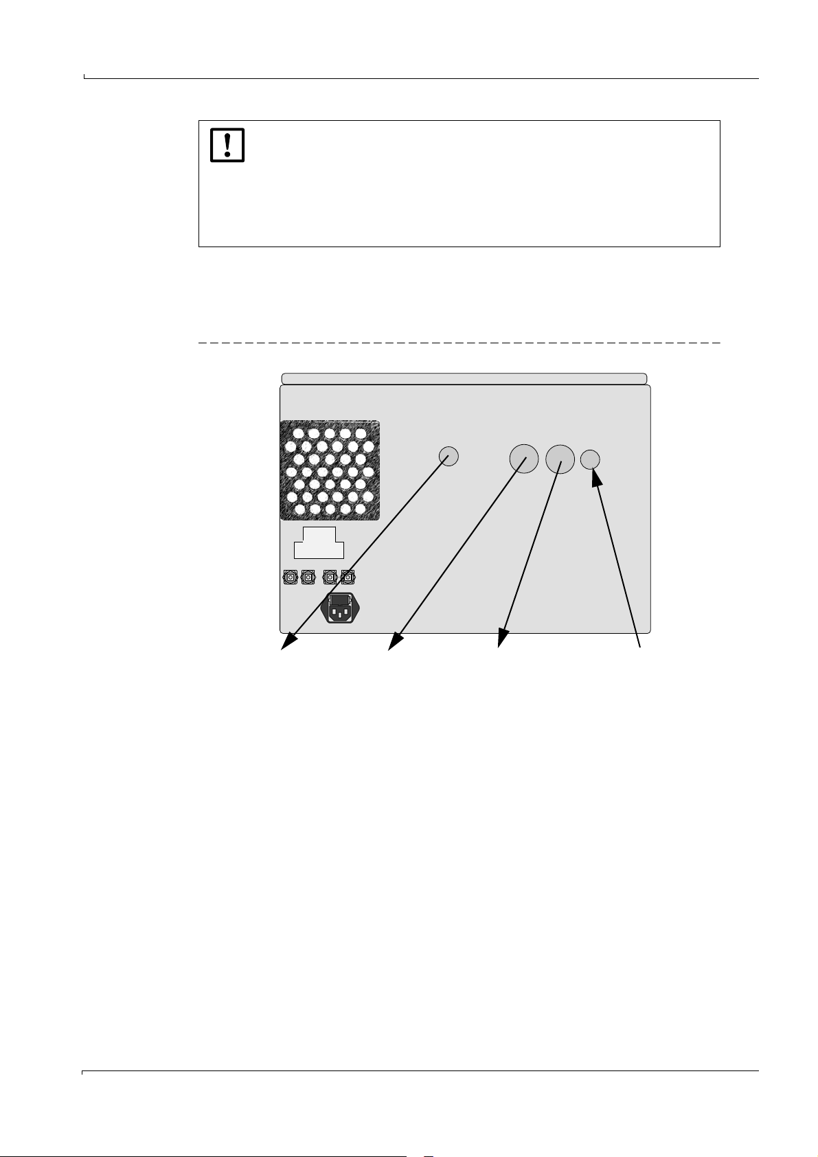
3.2.3 Interfaces
MA SL MA SL
E E S S
E S E S
I/O module box or HC8X
“MA” interfaces
MCS100E
“Module box” interfaces
3.2.3.1 Optical interfaces
The optical connections are located at the bottom of MCS100E.
Connecting the fiber optical cables:
⊗ Do not sharply bend the fiber optical cables.
• Minimum bending radius: 3 cm.
• The direction of the fiber optical cable can be as desired.
• The connectors can be plugged into the sockets in any 90° angle.
Press connector into socket until you hear that it is locked.
To remove the fiber optical cables, pull at the connector only (not at the cable).
Optical interface “module box“
I/O module boxes (digital and analog input/output units) or HC8X heating controllers are
connected to the interface to the “module box”.
• Max. length of recommended fiber optical cables: 50 m (for further information, refer to
Technical Data).
• Designation of the connections:
– At the MCS100E: Module box “E” or “S”
– At the module box:“MA E” or “MA S”
(MA = Master, E = Receiver, S = Sender)
Installation
Figure 5 Connection of “module box” interface
26 MCS100E Operating Instructions 8009504/VYWA7/V3-1/2018-01 © SICK AG
Subject to change without notice
Page 27
Installation
1 fiber optical
cable
2 fiber optical
cables
Converter to V24
Converter*
*Plug-in board or converter with inherent power supply
E S
E S E S
MCS100E
“PC/printer” interface
Only this 1 fiber optical cable
for the V24 converter for
printer
Converter
Interface
Optical interface “PC/printer“
Figure 6 Optical interface“PC/printer”
• The following equipment can be connected to the “Printer/PC” interface:
–Printer or PC
• Designation of the connections on the MCS100E:
“Printer/PC” “E” or “S” (E = receiver, S = sender)
• Maximum length of fiber optical cables: 50 m (unless required differently by the
receiver)
• An appropriate converter is used for connection of the fiber optical cables to the
electrical input of the terminal equipment.
Figure 7 Connection of “PC/Printer” interface
Subject to change without notice
MCS100E Operating Instructions 8009504/VYWA7/V3-1/2018-01 © SICK AG 27
Page 28
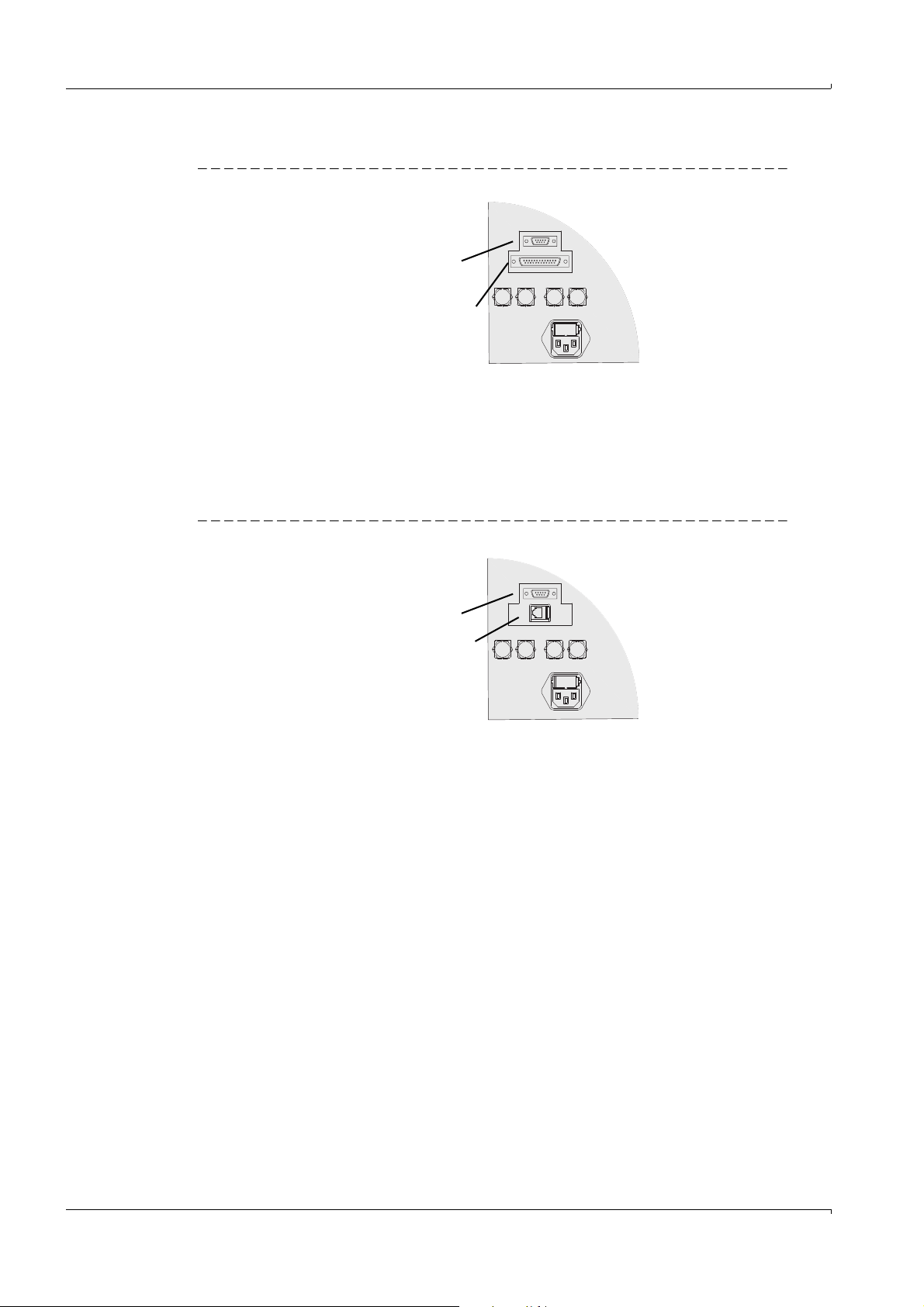
3.2.3.2 Electric serial and parallel interface (option)
RS232 interface
- PC
- Modem
Parallel interface
- Printer
Serial interface
- PC
Ethernet interface
- Ethernet
Figure 8 Connection to serial and parallel interface
• Serial line for PC or modem
• Parallel (“DOS-Interlink” cable 11-core) interface cable for printer.
• Use sufficiently screened cables.
• Max. cable length: Approx. 10 m
3.2.3.3 Electric serial and Ethernet interface (option)
Installation
Figure 9 Connection to serial and Ethernet interface
• Serial interface (→§3.2.3.2).
• Ethernet interface
–Type: Ethernet
–Protocol: UDP
– Connector: RJ 45
– Cable: Cross-over on PC, 1:1 on hub
– Data format: 10 MBit half-duplex
– Addresses (preset):
- IPADDRESS:192.168.0.x (see label on Ethernet interface)
- SUBNETMASK:255.255.255.0
28 MCS100E Operating Instructions 8009504/VYWA7/V3-1/2018-01 © SICK AG
Subject to change without notice
Page 29
Installation
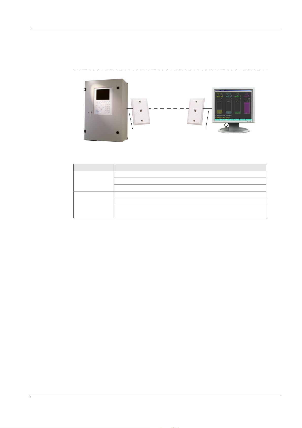
MCS100E
Ethernet
PC
Ethernet
line
Ethernet
line
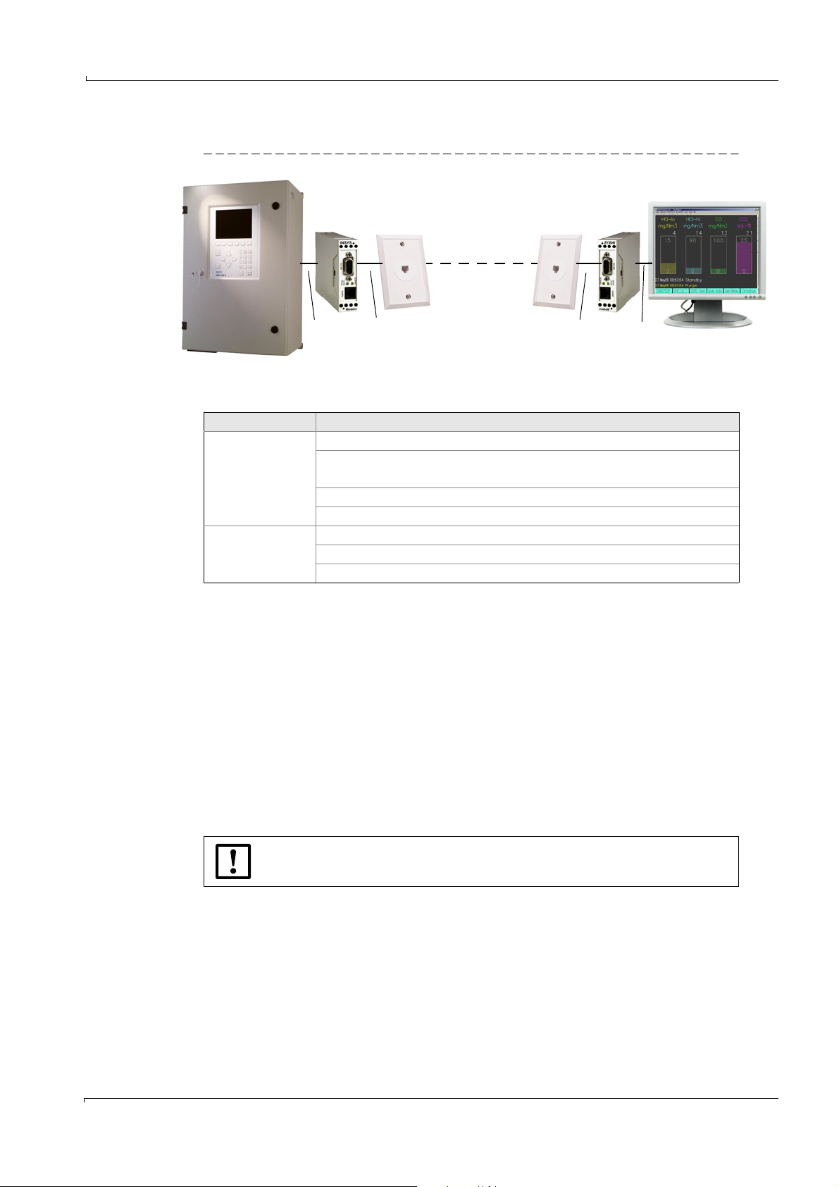
3.3 Remote control
3.3.1 Ethernet with TINY program
Figure 10 Remote control via Ethernet
Equipment
Control unit Equipment
MCS100E side
PC side
Ethernet interface RJ45 for MCS100E (Part No. 2043636)
Software package “TINY” (Part No. 2040228) (CD-ROM) (pre-installed)
Ethernet connection RJ45
Ethernet connection
Software package “TINY” (Part No. 2040228) (CD-ROM)
PC with Java (JDK or JRE) (Java JDK is included in the “TINY” software
package)
3.3.1.1 Connection on MCS100E side
Connect the MCS100E to the Ethernet.
3.3.1.2 Connection on PC side
Connect the PC to the Ethernet.
3.3.1.3 Program start on MCS100E side
First-time start:
1 The MCS100E starts.
2 Exit the MCS100E program (
→
p. 46, §5.4.2).
You are at DOS level.
3 Switch off the watchdogs (
→
p. 109, §7.8).
4 Call up: TSETUP <IP_ADDRESS> <IP_NETMASK> <IP_ROUTER>
The addresses depend on the customer network
Example:
- IP_ADDRESS : 192.168.0.x (x = 0 .. 9)
- IP_NETMASK: 255.255.255.0
- IP_ROUTER: 192.168.0.1
Call-up: TSETUP 192.168.0.1 255.255.255.0 192.168.0.1
Is it OK? [y,n] : <y> <ENTER> (saved in “C:\NOVELL\CLIENT32\NET.CFG”).
Subject to change without notice
5 Switch off the MCS100E.
Then automatic start when the MCS100E is switched on.
MCS100E Operating Instructions 8009504/VYWA7/V3-1/2018-01 © SICK AG 29
Page 30
3.3.1.4 Program start on PC side
First-time start:
1 Install Java JDK or Java JRE on the PC.
Installation file: In the “JAVAinst” directory on the CD.
2 Copy the “TINYclient” directory from the CD to the PC.
3 Using a text editor, enter the IP address of MCS100E in the “ts.bat” file.
Example:
- IP address of MCS100E: 192.168.0.1
java.exe -jar TinyClient.jar /Xde.kcf /D100 /K50 /R 192.168.0.1 password
4 If you want to call up the command line version of TINY:
- Connect with MCS100E.
- Call up “ts.bat”.
The DOS and the TINY windows are displayed on your PC.
OR
4 If you only want to view the TINY window:
- Start the Windows version of Java.
- Using a text editor, enter the IP address of MCS100E and display the path of the
“javaw” program to your Java installation in “Properties” of “Link”.
Example:
C:\Programms\Java\jdk1.5.0\bin\javaw.exe -jar TinyClient.jar /Xde.kcf /D100 /
K50 /R 192.168.0.1 password
Automatic start
1 - Call up “ts.bat”.
OR
1 If you only want to view the TINY window:
Double-click “Link” “ts”.
Installation
For further information, see the “xxxx_install.txt” file on your CD.
3.3.1.5 Special characters, e.g. on a German keyboard
Popup menu
Input of special characters in the MCS100E menus:
– Open a popup menu by clicking the window with the right mouse button.
– Click “Send Keystroke” “Custom Keys”.
If the required keys or characters are not shown in the popup menu: Define the keys in
a text file and call up the program with “/X<file name>” (
If the program is started in version “Call in DOS” (
codes are shown in a window.
For more information, see file “de.kcf” (open with a text editor) on your CD.
→
§3.3.1.4).
→
§3.3.1.4) with the “/C” option: The
Subject to change without notice
30 MCS100E Operating Instructions 8009504/VYWA7/V3-1/2018-01 © SICK AG
Page 31
Installation
MCS100E
RS232
RS232
Telephone line
Telephone line
PC
Modem ModemTelephone connection Telephone connection
3.3.2 Modem with the NetOP program
Figure 11 Remote control via modem
Equipment
Control unit Equipment
RS232 interface for MCS100E ((Part No. 2023049)
Modem (Part No. 6029430)
MCS100E side
Power supply unit 100 - 240 V, 24 V) (Part No. 6029654)
NetOP software (pre-installed)
Telephone connection (analog)
Telephone connection (analog)
PC side
Modem
NetOP software (Part No. 6029452).
3.3.2.1 Connection on MCS100E side
1 Connect the RS232C interface of MCS100E (
→
p. 28, Figure 8) to the modem.
The modem setting cannot be changed.
2 Connect the modem to the telephone network (analog).
3.3.2.2 Connection on PC side
1 Connect the modem to the telephone network (analog).
– If an external modem is used (this means: No modem PC card):
Connection of modem exclusively to a “real” COM port of the PC
- No USB ports
- No USB-to-COM ports
2 Set the modem corresponding to the PC.
3.3.2.3 Program start on MCS100E side
If NetOP has not been installed:
Leave the installation of NetOP to an expert.
1 Start MCS100E.
2 If NetOP has not been pre-installed:
– Copy directory \ndial to the root directory of MCS100E
– Check BIOS settings:
Subject to change without notice
- COM port: COM 4 or AUTO
- COM port may not be occupied already.
MCS100E Operating Instructions 8009504/VYWA7/V3-1/2018-01 © SICK AG 31
Page 32
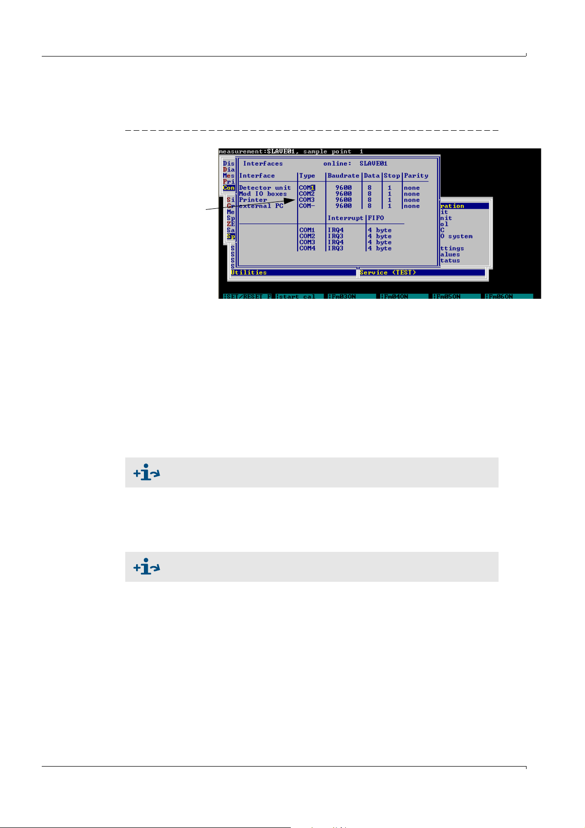
–In the Specialist menu: Utilities: Service: Environment Configuration: Interfaces
In this block
there may be no COM4
(
→
p. 93):
The “Interfaces” must not be assigned to any COM4. Example:
Figure 12 Settings
– Restart MCS100E.
3.3.2.4 Program start on PC side
1 Install NetOP on PC.
2 Start the NDGUEST.EXE program.
– At the first call-up: Set the parameters for NDGUEST according to the customer
network
Procedure:
→ documentation supplied with the delivery.
– “Quick DIAL”
Specify the telephone number of the MCS100E telephone connection (comma for
“Wait time”)
– The screen content of the MCS100E is shown.
Installation
File transfer via modem →p. 33, §3.4.2
3.3.2.5 Terminating the transfer
1 Switch to the NDGUEST user interface with <ALT-X>.
2 “Remote Control“- “Hang up”
3 “File” - “Exit”
For more information on NetOP → documentation supplied with the delivery.
Subject to change without notice
32 MCS100E Operating Instructions 8009504/VYWA7/V3-1/2018-01 © SICK AG
Page 33
Installation
3.4 Data transfer to/from external PC
3.4.1 Data transfer via fiber optical cable
1 Install the fiber optical cable connection (→p. 27, Figure 6).
2 The MCS100E measurement program must be installed and running on the PC (1.bat).
3 Start the desired data transfer on the MCS100E (for example
§5.7.15.4,
3.4.2 File transfer via modem
→
p. 91, §5.7.15.5).
For file transfer via modem, the running measuring operation must be
interrupted.
1 Install the modem connection (→p. 31, §3.3.2).
2 Exit the MCS program (
→
p. 46, §5.4.2).
3 Enter at DOS level:
a) wdog disable <ENTER>
b) cd\ndial <ENTER>
c) ndtrans <ENTER>
A transfer message is shown.
→
p. 86, § 5.7.11.14, →p. 90,
MCS100E is now at DOS level.
Use only the specified commands.
Otherwise, it is possible that the connection is interrupted; MCS100E
“hangs” at DOS level and can be restarted locally only.
d) Ctrl-Alt-x (call up NETOP).
e) Alt-T: Determine transfer direction and directories.
f) Start
Data transfer is running.
g) After the transfer, reply to the “Close file transfer window” prompt with “Yes”.
h) Change to the MCS100E screen with Alt-z.
i) Exit the transfer program with ESC.
j) Restart the MCS100E with “1”.
k) Change to NETOP again with Ctrl-Alt-x
4 Terminate the connection (
→
p. 31, §3.3.2)
Subject to change without notice
MCS100E Operating Instructions 8009504/VYWA7/V3-1/2018-01 © SICK AG 33
Page 34

3.5 Modbus communication protocol
Communication protocol: Modbus RTU →p. 126, §9.3
3.6 Hardware requirements for external PC
• If you want to install the operator menu on an external PC, the minimum requirements
are:
– IBM-compatible computer with 386 CPU
–1 MB DRAM
– 2 MB disk for internal programs
– 2 MB memory extension (required for data saving))
3.7 Hardware requirements for printer
•V24 interface
•IBM-compatible.
Installation
34 MCS100E Operating Instructions 8009504/VYWA7/V3-1/2018-01 © SICK AG
Subject to change without notice
Page 35
Installation
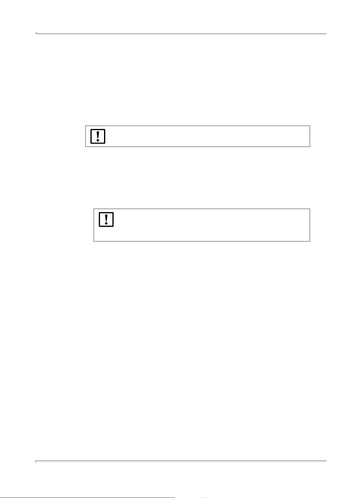
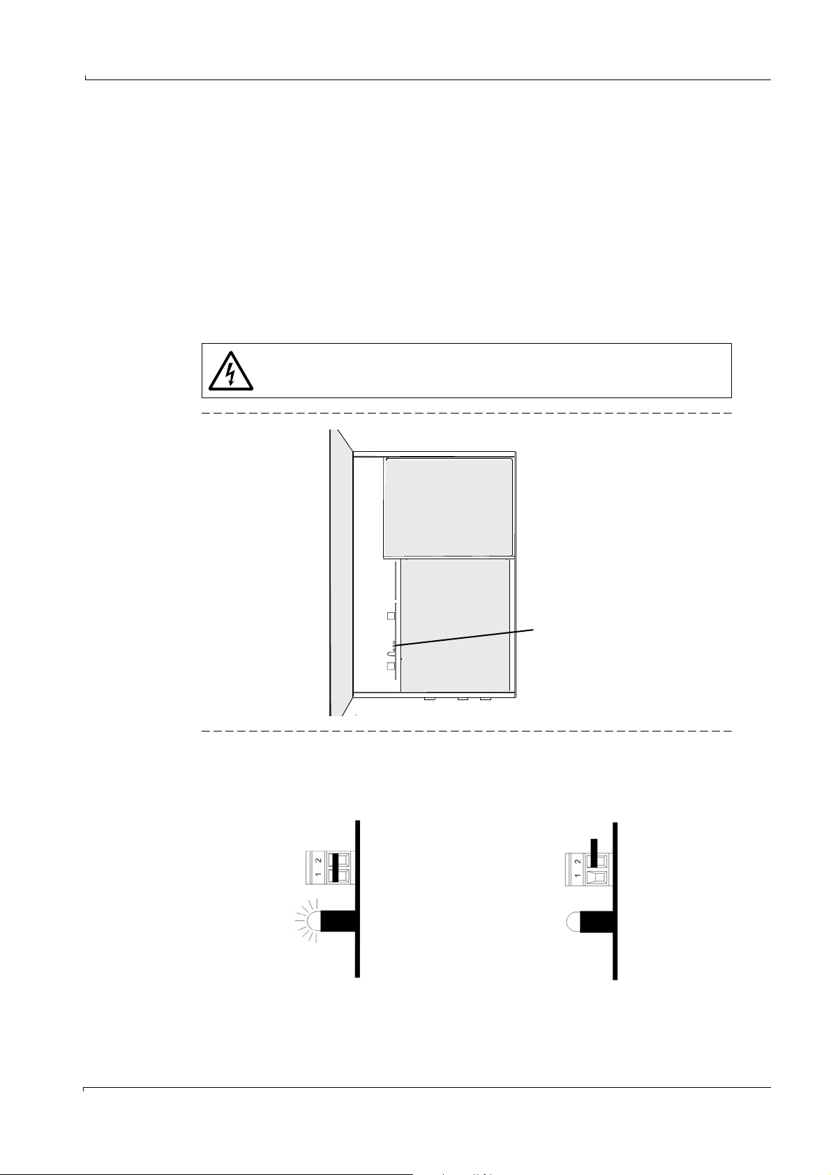
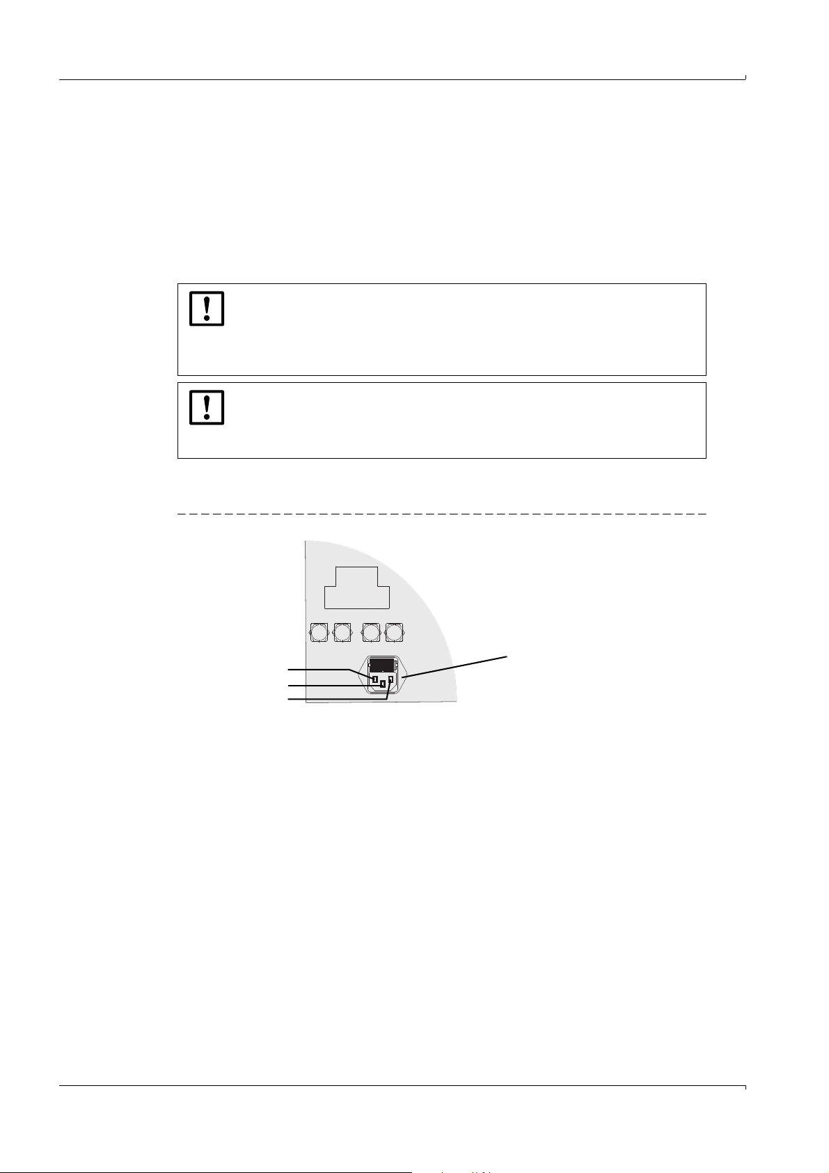
Bridge and LED
115 V
Bridge closed between pins 1 and 2.
The red LED is on if power is switched on.
230 V
Bridge open between pins 1 and 2.
The red LED is off if power is switched on.
3.8 Electrical installation
As soon as the power plug is connected to line power, MCS100E automatically starts
operation (
→
p. 38, § 4.1). Before connecting the power plug to the line power, ensure that all
necessary installation work has been done.
3.8.1 Power voltage adjustment
To adjust the power voltage:
Adjust bridge according to the requested power voltage (see below).
Use a backup with the current rating that corresponds to the power voltage (→p. 36,
§3.8.1.2).
3.8.1.1 Adjusting the bridge for power voltage
The current values of the power fuses are voltage-dependent.
Use different fuses if the power voltage changes (→§3.8.1.2).
Figure 13 Position of LED (red) and bridge for power voltage adjustment
Figure 14 Bridge and LED for adjustment of 115 V or 230 V
Subject to change without notice
MCS100E Operating Instructions 8009504/VYWA7/V3-1/2018-01 © SICK AG 35
Page 36

3.8.1.2 Power fuses
Fuse holder
1 Put MCS100E out of operation (
2 Remove power plug (otherwise the fuse holder cannot be opened)
• The fuse holder is inside the power plug housing.
Figure 15 Fuse holder
3 To remove the fuse holder, press the two notches at the sides and pull out.
→
p. 100, §6.1)
WARNING: Hazard caused by incorrect fuses.
The fuses are dependent on the power voltage.
Use only fuses with the required current rating and of the specified type for
replacement.
⊗ Do not use makeshift fuses.
⊗ Do not short-circuit the fuse holder.
Installation
•Fuse types
– 230 V: 5 AT (slo-blo) (2 each)
– 115 V: 10 AT (slo-blo) (2 each)
4 Put in fuses (2 fuses) of the correct rating.
5 Press fuse holder back into position.
6 Reconnect power plug.
Subject to change without notice
36 MCS100E Operating Instructions 8009504/VYWA7/V3-1/2018-01 © SICK AG
Page 37

Commissioning
MCS100E
4 Commissioning
Preparation
Power-on procedure
Function test
Subject to change without notice
MCS100E Operating Instructions 8009504/VYWA7/V3-1/2018-01 © SICK AG 37
Page 38
4.1 Commissioning
Power connection
L
N
PE
As soon as connected to line power (power plug connected), MCS100E automatically starts
operation.
In particular, check before power-on:
– Power voltage adjustment (
– Fuse ratings (depend on voltage) (
– Correct connection of the sample gas lines (
– Correct connection of the fiber optical cables (
NOTICE:
If a cold instrument is installed in a warm environment, there is a risk of
condensation inside the instrument.
Allow the instrument to stand for approx. 24 h to adopt ambient
temperature before switching on the supply voltage.
NOTICE:
The heating-up time of MCS100E is approx. 4 h.
Do not apply condensing gas to the instrument before the end of the
heating-up time.
For connection to line power, a grounded cord connector is used (the MCS100E does
not have a power switch).
→
p. 35, §3.8.1).
→
p. 36, §3.8.1.2).
→
p. 24, §3.2.2.1).
→
p. 26, §3.2.3.1).
Commissioning
Figure 16 Power connection at the bottom of MCS100E
The MCS100E is supplied with all parameters set.
It will start operating immediately after power-on.
Subject to change without notice
38 MCS100E Operating Instructions 8009504/VYWA7/V3-1/2018-01 © SICK AG
Page 39

Commissioning
4.2 External keyboard
To ease the entry of rather large volumes of data a standard type external keyboard can be
attached to the keyboard connector (DIN-connector with 5 poles) at the door.
4.2.1 Country-specific assignment of keys
Depending on the type of external keyboard attached, it may be necessary to adjust the
country-specific assignment of keys.
1 Switch MCS100E off and then on again.
2 Abort automatic start after query <Start Program Y/N> (
3 If you want to remain at DOS level for more than 4 minutes: Disable the watchdogs
(
→
p. 109, §7.8).
4 Start the “Norton Commander” at DOS level with: <c:\nc>
Note: Switch MCS100E off and on again before selecting the “Norton Commander”.
5 In the “Autoexec.bat” file (<F4>):
–Insert “rem(blank)” before the line with the previous language and
– delete “rem” before the line with the desired language.
Example: After switching from German (gr) to English (us):
– rem C:\dos\keyb gr,,c:\dos\keyboard.sys
– C:\dos\keyb\ us,,c:\dos\keyboard.sys
6 If required, enable watchdogs again (
7 Exit the “Norton Commander”.
8 Start the measurement program with 1.bat (
→
p. 109, §7.8).
→
→
p. 45, §5.3.2).
p. 45, §5.3.3)
To enable the display of country-specific characters on the screen, countryspecific code pages must be loaded. This task should only be carried out by a
specialist who is well-acquainted with MS-DOS.
4.3 Language selection of the MCS program
The language of the MCS program is set:
• In the MCSCONF configuration program “Directories and Files”
• In the measurement sequence program in menu option Specialist: Utilities: Service:
Environment Configuration: Text file.
4.4 Display setup
• Setting in the measurement program: (→p. 92, §5.7.15.7.1)
• Setting via external keyboard:
– CTRL ALT +
– CTRL ALT –
The settings are not saved.
Subject to change without notice
MCS100E Operating Instructions 8009504/VYWA7/V3-1/2018-01 © SICK AG 39
Page 40

Commissioning
40 MCS100E Operating Instructions 8009504/VYWA7/V3-1/2018-01 © SICK AG
Subject to change without notice
Page 41

Operation
MCS100E
5 Operation
Operation
Status messages
Subject to change without notice
MCS100E Operating Instructions 8009504/VYWA7/V3-1/2018-01 © SICK AG 41
Page 42
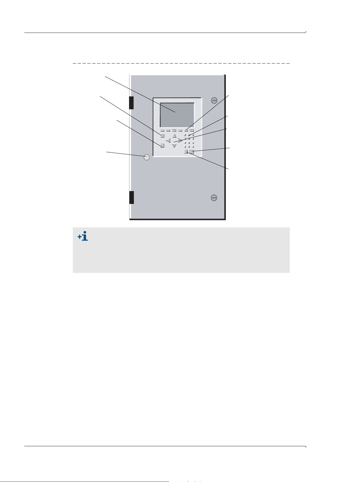
5.1 User interface
MCS 100 E
Key F1
Help
Monitor
Function keys
F3 ... F8
Numeric
keys
Cursor keys
Key
<ENTER>
Key
<ESC>
Key F2
Measured value
display
5-pole DIN
connector
for external
keyboard
Figure 17 Front of MCS100E with controls
Operation
Screen saver
The screen is automatically switched off after approx. 4 h if no key was pressed
during this period.
Press any key to switch the screen on again.
Normally, the “Digital Input 1” is designed for a corresponding external pin
switch (pre-set).
MCS100E is operated
• In measuring mode via the membrane keyboard.
• For setting parameters it is suitable to use an external keyboard (
5.1.1 Significance of keys
Arrow keys
Within the menus you can move up and down, resp. left and right using the arrow keys.
Numerical keys
Enter the appropriate characters into those lines where you are expected to enter figures
only. (Please use an external keyboard, if letters must be entered.)
<ESC> key
The <ESC> key is used to quit the menus, to terminate the program, to cancel a command,
etc. If modifications were entered you will be prompted whether to save or not.
<ENTER> key
The <ENTER> key is used to open a menu, to confirm entries, etc.
→
p. 39, §4.2).
Subject to change without notice
42 MCS100E Operating Instructions 8009504/VYWA7/V3-1/2018-01 © SICK AG
Page 43
Operation
F1 key (question mark)
The F1 key is used to go to a help menu. You will get help information on the actually used
menu. The help information is related to the highlighted line, resp. the field where the entry
mark is actually positioned. Use ESC to proceed within and/or quit the help menu.
From a menu field F1 displays:
• The revision number of the software
• The memory available on the flash disk
• The actually free main memory
• The assignment of the graphic buffers
• The addresses of the I/O module boxes connected
• General help
F2 key (measurement icon)
By means of the F2 key you quit the menu actually in use and return to the measured value
display. Any changes made beforehand in the menu will be ignored.
Function keys F3 ... F8 (softkeys)
Different actions can be initiated with the function keys F3 ... F8 (softkeys), depending on
the menu. The respective significance of the function key is shown at the bottom edge of
the screen above the respective key.
5.1.1.1 Entering alphanumerical characters
1 Highlight the line in question.
2 Keep pressing function key F8 until the required character is displayed in the function
key fields.
3 Press the function key which is positioned below the required character.
It is best to use an external keyboard for entering characters (→p. 39, §4.2).
Subject to change without notice
MCS100E Operating Instructions 8009504/VYWA7/V3-1/2018-01 © SICK AG 43
Page 44

5.2 Data and program storage
5.2.1 Structure of directories
The MCS100E software is located in a directory of its own,
containing:
• The configuration program
•The measurement program (1.bat) itself
• The text and help files (.txt and .hlp)
• Some other files associated with the program
The call-in .bat files (1.bat and mcsconf.bat) are in the directory C:\BAT\
Each “System” (
→
p. 68, §5.7.11) created in the measurement program automatically
creates an own subdirectory containing the system's default settings as well as the
measured values and the messages of the message lines. The name of this directory is
identical to the system's name.
Automatically and intermediately saved files are stored on drive d: (default setting).
The structure of the directories has to be entered in the configuration program (
§9.1.3.4) in Directories and Files.
5.2.2 Data files
The data files contain the measured values or status messages.
The name of the data files contains date and time of file creation, the last letter identifying
the type of file.
File name: MMtthhmm.jjx
→
p. 123,
Operation
MM: Month
tt: Day
hh: Hours
mm: Minutes
jj: Year
x: x = 1: Messages from status bar 1
x = 2: Messages from status bar 2
x = d: Measured values stored
Example: 01230856.09d: The file was created on January 23
contains measured values.
When 100 status messages are reached, a new file is automatically created (max. 5 files
per status bar, the oldest file is overwritten).
Memory required for measured values
Per component with a cycle time of 60 seconds => approx. 10 Kbyte memory required per
day.
The memory available is displayed in the main menu:
•Via function key F1
• In the graphics at the upper edge of the screen (when storage is “active”).
5.2.3 Program files
Files with names identical to their associated directory contain the measuring sequence
(=system).
rd
, 2009 at 08.56 and
Subject to change without notice
44 MCS100E Operating Instructions 8009504/VYWA7/V3-1/2018-01 © SICK AG
Page 45

Operation
5.3 Starting the measurement program
MCS100E starts the measurement program and thus measurement:
• Automatically when MCS100E (
• AT DOS level by means of the 1.bat program (
After the start of the measurements, the measured value display is shown.
To go to the main menu: Press <ESC>.
Which system (= measuring system) is started depends on the MCSCONF
(
→
p. 123, §9.1.3.4 Directories and Files).
If you wish another system to be started automatically, the entries in the
MCSCONF must be modified accordingly.
If you wish another system to be activated temporarily: Menu: Specialist:
System, activate for measurement.
5.3.1 Automatic start
Upon start, several prompts are displayed with which the automatic program start can be
aborted.
If there are no entries, the program starts automatically.
→
§5.3.1) is switched on.
→
§5.3.2).
5.3.2 Starting from the DOS level
Enter: 1 <ENTER>
Parameters for the 1.bat program
5.3.3 Aborting the start
To go to the DOS level: Answer within 2 seconds to <Start Program Y/N> with <N>.
If required, disable the watchdogs (→p. 109, §7.8).
→
p. 109, §7.7
Subject to change without notice
MCS100E Operating Instructions 8009504/VYWA7/V3-1/2018-01 © SICK AG 45
Page 46
5.4 Stopping and starting measurement
5.4.1 STOP, START measurement
Menu: Specialist: Utilities: Service: STOP, START measurement
• Upon measurement “STOP”, all interfaces (e.g. I/O module boxes) are inactivated.
• Upon measurement “START”, all interfaces are initialized anew and measurement is
started.
5.4.2 Quitting the measurement program
1 To quit the measurement program: Enter <ESC> repeatedly until a screen prompt for
exiting the measurement program is displayed.
2 A password must be entered.
The password input is not displayed on the screen.
Definition of password: →p. 121, §9.1.3.1
The password is identical with the password at “Specialist level”.
3 You are then at DOS level.
4 If required, disable the watchdogs (
→
p. 109, §7.8).
To be sure that - after having quit the program - MCS100E is in the basic
condition (important e.g. for configuration of the I/O module boxes):
Boot the MCS100E (<CTRL-ALT-DEL> or switch off/on).
Operation
46 MCS100E Operating Instructions 8009504/VYWA7/V3-1/2018-01 © SICK AG
Subject to change without notice
Page 47
Operation
Status bar 2
Status bar 1
Measurement sequence
(= system)
Sample point
5.5 Status bars
Figure 18 Status bars
Up to 3 status bars are displayed:
• At the top screen margin one information line with information on the current
measurement.
This line is not archived.
• Two status bars at the bottom screen margin:
– Upper line (status bar 2): Fix, contains the operational state.
– Lower line (status bar 1): Flashing, contains warnings and messages.
– If no status bar is displayed, there is no active status.
– Status bars 1 and 2 are saved in files (
→
p. 44, §5.2)
– Status bar 1 is output to the printer (if the on-line protocol Main Menu: Printer: Print
on-line: Protocol Start is active).
– If there are several active status messages, they are displayed successively (each
message for approx. 4 seconds).
– The texts associated to the status bars are programmed in the menu Specialist:
System edit: Message and corresp. relays.
Subject to change without notice
MCS100E Operating Instructions 8009504/VYWA7/V3-1/2018-01 © SICK AG 47
Page 48

5.6 Using the menus
5.6.1 In Menu fields
Selection of a sub-menu Arrow keys, then <ENTER>
Quit menus/graphics <ESC> (you are prompted whether or not to save
Selection from a list Arrow keys, then <ENTER>
Counting upwards in the numbering of lists <ENTER>
Counting downwards in the numbering of lists <–> (Minus key)
Entry of numbers Numerical keys
Entry of texts Alphanumerical keys
Switching from insertion to overwrite <INS (EINFG)>
Accept prompt <ENTER>
Reject prompt <ESC>
Interrupt printing <ESC>
5.6.2 In Entry menus
De-/Activate components ( )<ENTER>
Toggle (e.g. 0/4 .. 20 mA, decimals) <ENTER>
Activate an entry line <ENTER>
Entry of numbers (e.g. measurement ranges) Numerical keys
Entry of texts (e.g. messages) Alphanumerical keys
Copy text lines <Shift–F3>
Display list of names <Shift–F6>
Termination of entries:
Accept modifications performed
Reject modifications performed
Quit menus <ESC> (you are prompted whether or not to save
Operation
any modifications)
<ENTER>
<ESC>
any modifications)
You are not allowed to make entries in the fields that are automatically skipped. Entries in
these fields can only be made in the relevant menus (of the same name) in the specialist
level.
5.6.3 In file selection lists
Change sorting algorithms <–> or <+>
Go to top margin line <> (arrow key left)
Tag files <Space key>
Edit tagged files <ENTER>
Reject entries <ESC>
Subject to change without notice
48 MCS100E Operating Instructions 8009504/VYWA7/V3-1/2018-01 © SICK AG
Page 49

Operation
5.6.4 Safety prompts
Before saving changes in some menus you will be prompted whether or not the changes
should be accepted.
Yes The changes performed are accepted and saved.
No The changes performed are ignored.
In some menus you will be prompted additionally, whether or not the changes performed
should be accepted for the current measurement sequence.
Yes The changes performed are immediately applied to the current measurement sequence.
No The changes performed are saved and only applied after starting the next measurement
Function of keys
Accept safety prompt <J> (Y) or <ENTER> on Yes field
Reject safety prompt <N> on Yes field or <ENTER> on No/Cancel field
Ignore safety prompt <ESC>
1
Starting from the “Yes” field, the No/Cancel field will only be displayed when pressing “once the
arrow key, right”.
If the safety prompt is not answered within 120 seconds, then it will automatically be
answered “No”.
sequence.
1
Subject to change without notice
MCS100E Operating Instructions 8009504/VYWA7/V3-1/2018-01 © SICK AG 49
Page 50
5.7 Menus
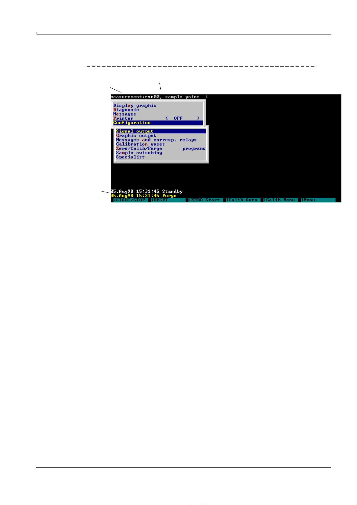
5.7.1 Main menu
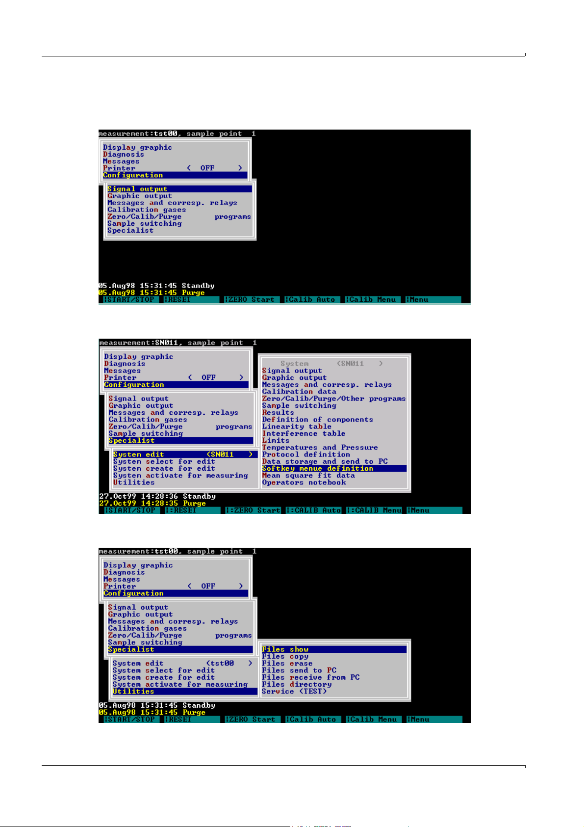
5.7.2 Specialist: System edit
Operation
5.7.3 Specialist: Utilities
50 MCS100E Operating Instructions 8009504/VYWA7/V3-1/2018-01 © SICK AG
Subject to change without notice
Page 51
Operation
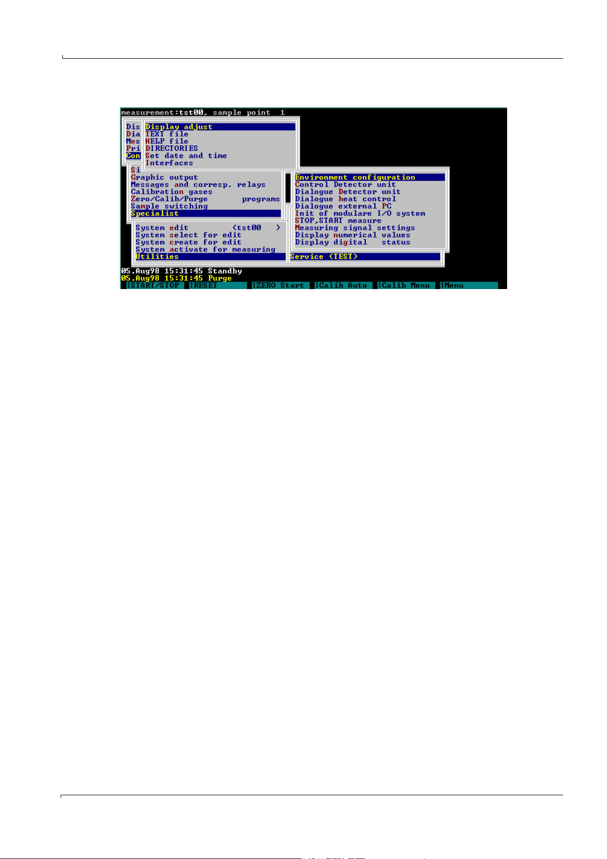
5.7.4 Specialist: Utilities: Service: Environment configuration
Subject to change without notice
MCS100E Operating Instructions 8009504/VYWA7/V3-1/2018-01 © SICK AG 51
Page 52
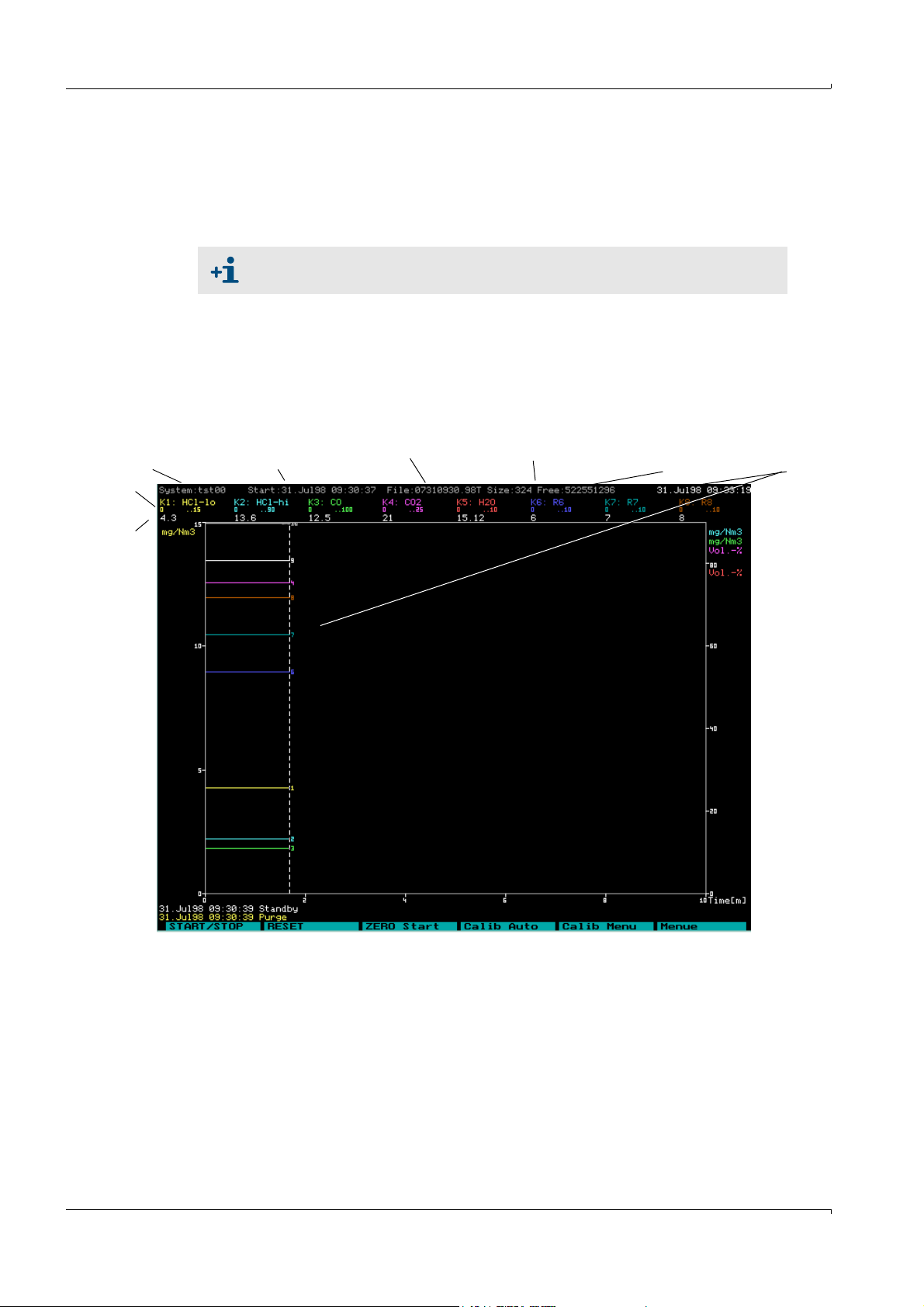
5.7.5 Display graphic
Measurement sequence
(= system)
Start time of
measurement
File File size Free
space on hard disk
Time at
cursor position
Measure-
ment range
Measured
value
Main Menu: Display graphic
In this menu option, you can select the graphic output of the measured values.
The graphic is displayed automatically after the start of the measurement program or if no
key has been pressed for 10 minutes (parameter KT upon program start).
If a menu is presented in the graphic, the graphic output will not be updated.
5.7.5.1 Graphic output: Time history
In this menu, the measured values are displayed over time, whereby totally 16 components
can be represented:
• Max. 8 components as lines with numerical values for measurement range and
measured value.
• Further 8 components as lines only.
Operation
52 MCS100E Operating Instructions 8009504/VYWA7/V3-1/2018-01 © SICK AG
Subject to change without notice
Page 53

Operation
Legend
Measurement
Name of measurement sequence.
sequence
Start If “Actual”: Start time of measurement sequence
If “Archive”: Start time of file
1
File Name (and thus time of creation of file)
.
File size Actual size of data file.
Free Memory still available on hard disk.
Time Time at cursor position.
If “Actual”: If no key was pressed for 10 seconds, the cursor jumps back on the
time axis to the end of the recording.
K1..K8 Represent the first 8 curves from Specialist: System edit: Graphic output with
- name of component
- measurement range
- measurement value at cursor time
Units, left Units of the first group of components which have an identical scale. The scale is
derived from Main menu: Configuration: Graphic output: Measurement ranges
and is automatically adapted to the current measurement range.
Units, right Units of the second group of components which have an identical scale.
All further units (of the up to 16 possible components) are displayed at the right
hand side and are scaled automatically according to their individual
measurement range (bottom 0%, top 100% of the measurement range,
independent of the scale displayed).
Time axis Time displayed
Status messages Upper (2
1
Displayed only if data storage is active.
2
If the status bar is empty: There is no current message
nd
) and lower (1st) status bar with current status messages2.
Key assignment
<- and ->: Move time axis
<5> Display of number of curve on/off
<F1> Help menu, there
0: If “Current“: Cursor to end of data recording.
If “Archive“: Non-stop data display
6: If “Current“: Cursor to end of data recording.
If “Archive“: Data display until end of screen
<F8> Menu with:
- Archive values
- Time axis
- Bar graph
<ESC>: Create new scale for graphic
<ESC> Quit graphic.
Subject to change without notice
MCS100E Operating Instructions 8009504/VYWA7/V3-1/2018-01 © SICK AG 53
Page 54

5.7.5.2 Graphic output: Bar graph
Component
Unit
Measured value
Measurement range
Bar
In this menu, the measured values are displayed as bar graph (assignment from Specialist:
System edit: Graphic output).
Max. 4 (of 16) bars can be presented at one time.
• The name of the measurement and the time are displayed in the first line (
§5.7.5.1).
• Underneath the names of the components the corresponding measurement ranges and
measured values are displayed (numerically and as bar graph).
→
Operation
p. 52,
Key assignment:
<- and -> Move bar and display next bar.
<F8> Switch over to graphic “Time axis”.
<ESC> Quit graphic and return to Main Menu
5.7.5.3 Archive Data
The measuring values stored in the archive are displayed.
You are prompted to enter the start time (see next chapter).
The graphic output of the values stored in archive corresponds to that of the actual values
in Main Menu: Display graphic Graphic output: Time History.
There is no influence on the current measurement sequence.
Key assignment
<- and ->: Move time axis
<F1> Help menu, there
<F8> Menu with:
<ESC> Quit graphic.
At the end of a data file the next file in chronological order is opened automatically and the
data continues to be displayed.
0: Non-stop data display (Stop: Press any key)
6: Display of data until end of screen or press any key
Display of current values
Scale time axis
Data reduction (indicated value x means: every xth measured value is to be displayed)
<ESC>: Create new scale for graphic
Subject to change without notice
54 MCS100E Operating Instructions 8009504/VYWA7/V3-1/2018-01 © SICK AG
Page 55

Operation
5.7.6 Diagnosis
The cause for a stop in recording of the last data file stored is displayed at the left bottom
corner of the screen. If the cause seems unknown: “Unknown Stop Condition” is displayed.
Start time
The start time of the files stored in archive is indicated here.
Format:
dd.mm.yy hh.mm.ss (day.month.year hour.minute.second)
Time axis
The time scale (x-axis) of the time history is set here.
It is only after quitting the entry field that the display on the screen is updated.
The scale for the unit axis (y-axis) is set in the menu Main Menu: Configuration:
Graphic output.
Main Menu: Diagnosis
This menu option presents the status of the measurement sequence.
A list is displayed from which messages, the active components, temperatures, etc. can be
selected for subsequent display.
While this menu option is active, the <F2> key (display of measured values) is disabled.
Settings:
Messages Display of current messages
Temperatures
1
No. Numbering
The following temperatures are default settings
1: O
sensor
2
2: Detector
3: Cell
4: Filter wheels
5: Heating controller 1, 1
6: Heating controller 1, 2
st
controller
nd
controller
7: Heating controller 2, 1st controller
8: Heating controller 2, 2
nd
controller
Name Name
Current Current value
Nominal Nominal value
Hysteresis The hysteresis (in °C) defines the switching thresholds of the
temperature controller
Limit Limit monitoring
ERROR 1: Current value > NOMINAL VALUE+limit high
1: Current value < NOMINAL VALUE-limit low
0: Limit not exceeded
ALARM 1: Current value > nominal value+limit high
remains set until RESET is carried out
1
Additional information and settings --> menu: Specialist: System edit: Temperatures and Pressure
Subject to change without notice
MCS100E Operating Instructions 8009504/VYWA7/V3-1/2018-01 © SICK AG 55
Page 56

Settings
Components Result number of the component
Name of component (selectable)
To the right of the
Component
Measurement range (measurement range 2 fullscale).
Operation
Amplification Amplification level of measuring resp. reference
signal
1 = lowest, 19 = highest level.
The subsequent number represents the gain factor
Max. energy is:
Level 1 100% => 232,000 counts
Reference Signal,
Measuring Signal
Counts: The counts increase with the gain factor.
Percent: Value independent of the gain factor.
Example:
Gain fct. 1 and 232,000 counts => 100%
Gain fct. 2 and 232,000 counts => 50%
etc.
Absorbance, no corr. Absorbance, no correction
Absorbance add. corr. Additively and multiplicatively corrected
absorbance
corr.Absorbance: Calculated concentration
Concentration Drift since the first zero setting
Drift total ZERO Related to concentration in % of the measurement
range (displayed at the top).
Drift last ZERO Drift since the last (current) zero setting
Related to concentration in % of the measurement
range (displayed at the top).
Drift total SPAN Drift since the first calibration in % of measurement
range (displayed at the top).
Drift last SPAN Drift since the last calibration in % of measurement
range (displayed at the top).
T90 Time: T90 time in seconds.
Measuring cycle Measurement frequency (for all of the components
together).
5.7.7 Messages
Main Menu: Messages
The messages stored in archive from status bar 1 (lower bar) are displayed.
Switching to the messages of status bar 2: <ESC>.
These messages are output automatically to the printer, if the printer is active (Main Menu:
Printer: Print on-line: Protocol Start).
The latest message is stated at the top.
Up to 192 messages are stored.
56 MCS100E Operating Instructions 8009504/VYWA7/V3-1/2018-01 © SICK AG
Subject to change without notice
Page 57

Operation
5.7.8 Print (On/Off)
Main Menu: Printer
Output is possible:
• With Print on-line: To a printer.
• With Print archive, output of stored values: To the printer, a file or the screen.
5.7.8.1 Print on-line (On/Off)
Main Menu: Printer: Print on-line
This menu option controls the output of the current measured values to the printer. For this
purpose, “protocols” (see next chapter) are defined.
The name of the current measurement sequence is displayed in parentheses.
Upon selection of the menu, a sub-menu is displayed from which you can select the
protocol definition or start and stop a printer.
If a printer protocol is active, a mark () and the text “ON” are displayed.
Protocol Definition
Main Menu: Printer: Print on-line: Protocol Definition
This menu option is used to perform the settings for the protocol of the current measured
values.
5 types of protocols can be created and given a name - to ease identification.
Settings
Protocol type (1..5) Selection of one of the 5 protocol types
Name These names are used to ease identification, e.g. at protocol start and stop.
Output to Only “Printer” possible
Filtering Yes:
Addition over the cycle time, divided by the number of measured values and
subsequent output of the value.
No:
Actually current value is output
Cycle [Min]: Output cycle time (in minutes) for printing.
0: Per measurement cycle one value is output.
Component selection Selection of the components that are to be printed.
(The list is derived from the menu Specialist: System edit: Results).
By <ENTER> a list containing the actual components is displayed. If a field is
selected within this list, then a list containing the possible components is
presented.
xxxxx.xx defines the format for display of the measured values, in this example 2
digits following the decimal point; changeable with <ENTER>.
Characters per line Number of characters per line dependent on the paper format.
Default setting: 80
Lines per page Number of lines per page dependent on the paper format. Default setting: 72
Decimal separator Decimal separator Comma or point
Format date Format of date, change with <ENTER>.
Separator of date Separator of date: . or /
Separator of time Separator of time: 14:55:00 or 14-55-00
Note: The separators of date and time should be different to enable an
evaluation program to find a distinguishing feature.
File extension for the protocol files is ”.txt”. Protocol files can be edited in the
usual table calculation programs.
Subject to change without notice
MCS100E Operating Instructions 8009504/VYWA7/V3-1/2018-01 © SICK AG 57
Protocol changes are executed immediately.
Page 58

Protocol Start
Main Menu: Printer: Print on-line: Protocol Start
Upon entering the protocol name in this menu option one of the 5 on-line protocols defined
is started. Then all messages of message line 1 as well as the zero and calibration
programs are automatically output to the printer. Only one protocol can be started.
Protocol Stop
Main Menu: Printer: Print on-line: Protocol Stop
The active printer protocol is stopped.
The active printer protocol is displayed and you are prompted whether or not it is to be
terminated.
5.7.8.2 Print Archive (Name)
Main Menu: Printer: Print Archive
This menu option controls the output of the archived measured values to the printer, to a
file or to the screen. For this purpose “protocols” (see next chapter) are defined and the
start and end times are entered, and then the protocol is started (whereby, if necessary,
you will be prompted for the file name).
The name (name) of the archived measurement sequence selected for printing is displayed
in parentheses. This name can be selected in the menu Specialist: System, select for
editing.
Operation
5.7.8.3 Start and end
Main Menu: Printer: Print Archive Start and end
Enter start and end time of the protocol to be output, here.
Upon start, the protocol will begin with the 1st time entry found and continue until the last,
respectively until time end. Missing times are printed as empty lines.
5.7.8.4 Protocol Definition
Main Menu: Printer: Print Archive Protocol Definition
This menu option is used to perform the settings for the protocol of the saved data
5 types of protocols can be created and given a name - to ease identification. The entries to
be made correspond to those for the on-line protocol, however, the protocol of archived
data can additionally be output to a file or to the screen.
58 MCS100E Operating Instructions 8009504/VYWA7/V3-1/2018-01 © SICK AG
Subject to change without notice
Page 59

Operation
Settings:
Protocol type (1..5) Selection of one of the 5 protocol types
Name These names are used to ease identification, e.g. at protocol start and stop.
Output to Printer
File
Monitor
Filtering Yes:
Addition over the cycle time, divided by the number of measured values and
subsequent output of the value.
No:
Actually current value is output
Cycle [Min]: Output cycle time (in minutes) for printing.
0: Per measurement cycle one value is output.
Component selection Selection of the components that are to be printed.
(The list is derived from the menu Specialist: System edit: Results).
By <ENTER> a list containing the actual components is displayed. If a field is
selected within this list, then a list containing the possible components is
presented.
xxxxx.xx defines the format for display of the measured values, in this example 2
digits following the decimal point; changeable with <ENTER>.
Characters per line Number of characters per line dependent on the paper format. Default setting:
80
Lines per page Number of lines per page dependent on the paper format. Default setting: 72
Decimal separator Decimal separator Comma or point
Format date Format of date, change with <ENTER>.
Separator of date Separator of date: . or /
Separator of time Separator of time: 14:55:00 or 14-55-00
Note: The separators of date and time should be different to enable an
evaluation program to find a distinguishing feature.
Separator, column 9: TAB stop
Separator for individual measured values.
The decimal value of the ASCII character is entered here as these are usually
non-printable characters.
Separator, line 13, 10: CARRIAGE RETURN, LINEFEED
The entry of 2 characters is mandatory.
The decimal value of the ASCII characters is entered here as these are usually
non-printable characters.
File extension for the protocol files is ”.txt”. Protocol files can be edited in the usual table
calculation programs.
The printer protocol settings Main Menu: Printer: Print Archive Protocol Definition and
Specialist: System edit: Protocol Definition are identical.
5.7.8.5 Protocol Start
Main Menu: Printer: Print Archive Protocol Start
Enter here which type of protocol for data stored in archive should be started. When
selecting a protocol with data output to a file, you will be prompted for the file name.
Before starting the output, make sure to terminate current on-line output, if
necessary.
Protocol output of stored data is started.
Subject to change without notice
MCS100E Operating Instructions 8009504/VYWA7/V3-1/2018-01 © SICK AG 59
Output can be interrupted with <ESC>.
Page 60
5.7.8.6 Print diagnosis
Main Menu: Printer: Print Diagnosis
A diagnosis is printed, i.e. all active messaged, temperatures and components.
Before starting the output, make sure to terminate current on-line output, if
necessary.
5.7.8.7 Print Messages
Main Menu: Printer: Print Messages
The status messages of status bars 1 and 2 are printed.
Before starting the output, make sure to terminate current on-line output, if
necessary.
5.7.8.8 Print System data
Main Menu: Printer: Print System data
A list is displayed for selection of the MCS100E data to be printed. Upon selection of the
system data you will be prompted whether or not to start printing. If you wish to print into a
file, then you have to indicate the file name when prompted.
While this menu option is active, the <F2> key (display of measured values) is disabled.
Operation
Before starting the output, make sure to terminate current on-line output, if
necessary.
60 MCS100E Operating Instructions 8009504/VYWA7/V3-1/2018-01 © SICK AG
Subject to change without notice
Page 61

Operation
5.7.9 Configuration
Main Menu: Configuration
5.7.9.1 Password for the configuration level
A password has to be entered to edit the menus “Signal output” and “Graphic output”.
The password input is not displayed on the screen.
Definition of password: →p. 121, §9.1.3.1
5.7.9.2 Signal output
Main Menu: Configuration: Signal output
This menu option is used to define the:
• analog signal outputs and the
• Measurement ranges
Settings
Channel Number of the analog output.
Mark () Analog output active ( )/not active.
Name Name of component derived from a list which is based on Specialist: System edit:
Results.
Display list by pressing <ENTER>
Unit Unit of component. Displayed automatically from Specialist: System edit: Results
Measurement
ranges
Switching of the measurement range is programmed here.
Measurement range 2 is the larger measurement range and relevant for the plausibil-
ity check for zero setting- and for calibration, with the drifts etc.
The measurement ranges are automatically switched over (this is also true for the
graphic output). Switching over can be interrogated in the menu Specialist: System
edit: Zero/Calib/Purge programs/other programs
Hysteresis is 5%.
If a component has been defined more than once, then the 1
for the plausibility check.
Relays Number: Number of the relay
The relay “Number” is activated (deactivated) when the measurement range 2 (1) is
active (the relay indicates that the analog output switched to another output range).
0: No relay to be assigned
- Number: Inverted setting
Current 0..20 mA
4..20 mA
(Variable RHi).
st
definition is relevant
Max. 32 outputs can be activated.
The menu option is identical to Specialist: System edit: Signal output
Subject to change without notice
MCS100E Operating Instructions 8009504/VYWA7/V3-1/2018-01 © SICK AG 61
Page 62
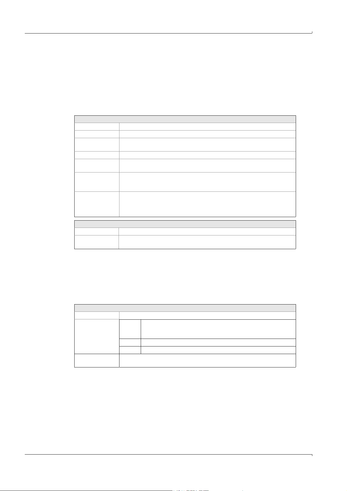
5.7.9.3 Graphic output
Main Menu: Configuration: Graphic output
This menu option is used to define the graphic.
32 channels can be defined.
In Time History, 16 lines can be represented simultaneously, the first 8 lines with
corresponding values.
With the bar graphs, 4 (four) bars (of max. 16) can be represented simultaneously,
whereby it is possible to scroll with the arrow keys right/left.
Settings
Channel Numbering (no further significance)
Mark () The channel is/is not displayed in the graphic
Name Name of component Derived from a list which is based on
Unit Unit of component. Displayed automatically.
Limit values When entering a mark (
Measurement
ranges
Decimal Defines the display of the measured values in the bar graph menu, e.g. xxxx.xxx = 3
Specialist: System edit:
Results
. Display of list by <ENTER>.
), the limits defined in Specialist: System edit: Limits are
displayed as lines in the graphics.
Scale of y-axis in time history.
2 scales are possible, which can be switched over automatically depending on the
measurement range.
digits following the decimal point. Adjustable by <ENTER>. In the time graphic, the
display of the numerical values shows always the complete sequence of digits
following the decimal point.
Operation
Key assignment:
F7 Copy line from signal output.
F8 Set standard (adopt measurement ranges from Specialist: System edit: Signal
output).
The menu option is identical to Specialist: System edit: Graphic output
5.7.9.4 Messages and corresp. relays
Main Menu: Configuration: Messages and corresp. relays
In this menu the relays that are marked with “x” in the upper line can be assigned to texts.
This means, the relay is set/reset corresponding to the text which is displayed on the
screen.
Settings
Relays 2 relays (left and right column) are possible.
Number Number Number of the relay
(Selection only
possible, if marked with x in a.m. list)
0 No relay to be assigned
-Number Inverted setting
System status The texts are displayed in the same order as defined in Specialist: System edit:
Message and corresp. relays.
The free relays and texts are defined in the menu Specialist: System edit: Messages and
corresp. relays
62 MCS100E Operating Instructions 8009504/VYWA7/V3-1/2018-01 © SICK AG
Subject to change without notice
Page 63

Operation
5.7.9.5 Calibration gases
Main Menu: Configuration: Calibration gases
In this menu, zero and calibration gas sampling is adjusted and controlled.
Settings
Component List of active components (based on Specialist: System edit: Results). As soon as you
Measurement
range
Calib gas conc. Span gas concentration of the span gas connected (enter).
Plausibility
limits in % of
meas. range for
Zero and Calib.
value
Drift (% meas.
range):
reach the field for the component O2, there is an automatic switch-over to the menu
containing the O2 data (see below).
Measurement range is entered automatically (from Specialist: System edit: Results).
The value to be entered (default setting: 6%) defines the tolerance (in % of full scale)
which must not be exceeded by Zero- resp. calib. gas sampling (since the last
monitoring).
If the value measured at Zero resp. calib. gas sampling is within the tolerance as
entered here: The measured value is accepted.
If the value measured at Zero resp. calib. gas sampling exceeds the tolerance as
entered here: The measured value is accepted, but a message is output to the printer
and a flag (Zero: ER17, Calib ER17: ER18) is set for interrogation in Specialist: System
edit: Zero/Calib/Purge programs/other programs.
0: No plausibility control, calibration is always performed.
The drift with the Zero resp. calib. gas sampling control is automatically entered here.
Last: Drift since last control
Total: Drift since first control, e.g. last service
These values are also displayed in the main menu option “Diagnosis”.
Subject to change without notice
MCS100E Operating Instructions 8009504/VYWA7/V3-1/2018-01 © SICK AG 63
Page 64

O2 menu field
This menu defines the calibration of the O
sensor.
2
Span gas sampling is performed either manually from this menu or automatically via the
calibration program Specialist: System edit: Zero/Calib/Purge/Other programs (Flag C16
for component 16).
Calibration can be interrupted by either <ESC> or resetting the flag or by interrupting the
calibration program.
During calibration, a message indicates for how long the O
actual O
values are displayed continuously.
2
signal still has to be stable. The
2
In case of a malfunction during calibration a corresponding error message is generated.
The O
calibration data are stored in an individual file (SNxxx.O2C).
2
Settings
Temperature high Nominal temperature, as set (from Specialist: System edit: Temperatures)
Analog In low..high [mV] Scales the 12 bit analog input:
Example: -250 mV .. +250 mV
Span gas 1 and 2 [%] Enter span gas concentration in %
Span gas 1: High concentration
Span gas 2: Low concentration
Example: 20.95 .. 2.1.
Span gas 1 and 2 [mV] Display span gas 1 and 2 in mV,
values and tolerance (e.g. ±0.25) can also be entered manually.
Example: 0.00 .. 47.00 (±0.25)
Line constant [mV] Line constant as calculated upon calibration. Value (-25 .. 10). Can also be
entered manually.
Example: 0
Steepness [mV] Steepness as calculated during calibration. Value (35 .. 55). Can also be
entered manually.
Example: 47
Actual [digit] [mV] [%] Actual value in digits, mV, %
Relay for span gas 1 The relays that are to be set resp. reset (-) upon sampling of span gas 1 can
be entered here.
Relay for span gas 2 The relays that are to be set resp. reset (-) upon sampling of span gas 2 can
be entered here.
Time Stability, Timeout Time stability: 120 (example)
The measured value must remain constant for minimum this time
(120 sec. in the example), otherwise the calibration will start from the
beginning.
Time timeout: 900 (example)
If no stable measured value is obtained within this time (900 sec. in the
example), then the calibration is terminated and an error message (ER18)
is displayed.
Start CALIB with 1 point <ENTER> starts calibration with 1 point.
If calibration was successful, a prompt is displayed “Accept?”. When the
answer is YES, then line constant and steepness are calculated.
If calibration was not successful, then the value will be accepted anyway
but an error message (ER18) is displayed.
In case of a timeout the value is not accepted and an error message (ER18)
is displayed.
Start CALIB with 2 points The same as for point 1, but the 2
nd
test gas follows after the 1st test gas.
Set default values “Yes”: Default values are set.
Operation
64 MCS100E Operating Instructions 8009504/VYWA7/V3-1/2018-01 © SICK AG
Subject to change without notice
Page 65

Operation
5.7.9.6 Zero/Calib/Purge programs
Main Menu: Configuration: Zero/Calib/Purge programs
The programs ZERO, Calibration and Backpurge (of sampling probe) can be adjusted here.
Each second the programs are interrogated cyclically. If the conditions are met, then the
actions are performed.
Active programs, digital conditions, flags etc. can be viewed in Specialist: Utilities: Service:
Display digital status.
As the programs ZERO, calibration and backpurge are factory-programmed, you only need
(and can) enter/modify the times here. The information displayed is based on the entries in
the menu Specialist: System edit: Zero/Calib/Purge programs/other programs.
If the program definitions for ZERO, calibration or backpurge do not exist, the menu cannot
be opened.
Settings
Program Number Number of program.
Program name Name of program.
Active Mark () = program becomes immediately active upon software start.
Cycle Cycle, indicating how often the program will run.
Start When starting the measuring sequence the start of this program is
Duration minutes Duration of time program, thereafter the program becomes inactive again and
Hold minutes As of the start of the program, the analog output is held for this period in
Average at minutes Average from this time until final time. (This makes it possible to wait for rise
Only for the backpurge program:
Interval Total interval containing the pulse time
Length of pulse Duration of the backpurge pulse
Relays The pulse triggers the relay defined here.
DD:HH:MM: day:hour:minute
synchronized to this time.
Flag|hh:mm: Flag number OR hour:minute
has to be started anew.
0: Program is continuously running.
minutes and then released.
0: Analog output is not held.
times.)
At the end of a backpurge program the relay is always set to the rest state. (No
entries possible in this menu.)
Subject to change without notice
MCS100E Operating Instructions 8009504/VYWA7/V3-1/2018-01 © SICK AG 65
Page 66

5.7.9.7 Sample switching
Main Menu: Configuration: Sample switching
With MCS100E sample (point) switching is possible.by switching cyclically from one sample
point to the next. The system is pre-purged for a selectable time with the new sample gas,
before the new measured value is accepted.
Settings
No. of Sample points Number (max. 16) of sample points (No entries possible in this menu.)
Start time When starting the MCS100E, the start of sample switching is
Sample point number: active Number of sample point to be edited
Values hold/zero Defines whether the values from the inactive (=not being measured)
Remote control Inclusion of sample point into sample point switching via digital input.
Internal control Inclusion of sample point into sample point switching via flag.
Sample selected minutes Specifies in minutes for how long the sample point will be active.
Sample selected relay THIS relay will be set/reset (-) as soon as the sample point is active.
Sample data valid minutes Defines the pre-purge period. The “last” minutes are “valid”.
Sample data valid relay THIS relay will be set/reset (-) as soon as pre-purge is terminated and
Operation
synchronized to this time.
Mark () = sample point is being measured
sample point should be held (“Hold”) or set to zero (“Zero Setting”).
Select number of digital input. (LOGICAL AND by “Internal control”)
Select number of flag. (LOGICAL AND by “Remote control”)
measurement is performed at the sample point.
The menu is based on the menu option Specialist: System edit: Sample switching
66 MCS100E Operating Instructions 8009504/VYWA7/V3-1/2018-01 © SICK AG
Subject to change without notice
Page 67
Operation
5.7.10 Specialist menus
The specialist level is used to program the measurement sequence (= the system) and to
perform software settings.
Wrong entries in the specialist menu can have a disruptive effect on the
measurement sequence, lead to incorrect measurement results and may
damage internal and external system components.
Entries in the specialist menu may only be made by aptly trained personnel.
In the specialist level some menu options from the freely accessible Main
Menu are repeated. This is to avoid the time-consuming “jumping” from one
level to the other.
5.7.10.1 Password for the specialist level
To edit the specialist level, a password has to be entered.
The password input is not displayed on the screen.
Definition of password: →p. 121, §9.1.3.1
Subject to change without notice
MCS100E Operating Instructions 8009504/VYWA7/V3-1/2018-01 © SICK AG 67
Page 68

5.7.11 System edit (Name)
Specialist: System edit
This menu option contains the configuration for the system (= the measurement sequence)
name. The system to be configured can be:
• The actually active system. In this case any modifications to the settings have an
immediate effect on the configuration.
•A system that is not active at the moment (Selected in: Specialist: System, select for
editing). In this case, there is no effect on the actually active system. The system edited
can subsequently be activated via Specialist: System, activate for measurement.
5.7.11.1 Signal output
Specialist: System edit: Signal output
The following are defined here:
• Analog signal outputs
• Measurement ranges
Settings
Channel Number of the analog output.
Mark () Analog output active ( )/not active.
Name Name of component derived from a list which is based on Specialist: System edit:
Results.
Display list by pressing <ENTER>
Unit Unit of component. Displayed automatically from Specialist: System edit: Results
Measurement
ranges
Switching of the measurement range is programmed here.
Measurement range 2 is the larger measurement range and relevant for the
plausibility check for zero setting- and for calibration, with the drifts etc.
The measurement ranges are automatically switched over (this is also true for the
graphic output). Switching over can be interrogated in the menu Specialist: System
edit: Zero/Calib/Purge programs/other programs
Hysteresis is 5%.
If one component has been defined more than once, then the 1st definition is
relevant for the plausibility check.
Relays Number: Number of the relay
The relay “Number” is activated (deactivated) when the measurement range 2 (1) is
active (the relay indicates that the analog output switched to another output range).
0: No relay to be assigned
- Number: Inverted setting
Current 0..20 mA
4..20 mA
Operation
(Variable RHi).
Max. 32 outputs can be activated.
The menu option is identical to Main Menu: Configuration: Signal output
68 MCS100E Operating Instructions 8009504/VYWA7/V3-1/2018-01 © SICK AG
Subject to change without notice
Page 69

Operation
5.7.11.2 Graphic output
Specialist: System edit: Graphic output
This menu option is used to define the graphic.
32 channels can be defined.
In Time History, 16 lines can be displayed simultaneously, whereby the first 8 lines are
depicted with their measured values at the top.
With the bar graphs, 4 (four) bars (of max. 16) can be represented simultaneously,
whereby it is possible to scroll with the arrow keys right/left.
Settings
Channel Numbering (no further significance)
Mark () The channel is/is not displayed in the graphic
Name Name of component Derived from a list which is based on
Unit Unit of component. Displayed automatically.
Limit values When entering a mark (
Measurement
ranges
Decimal Defines the display of the measured values in the bar graph menu, e.g. xxxx.xxx = 3
Specialist: System edit:
Results
. Display of list by <ENTER>.
), the limits defined in Specialist: System edit: Limits are
displayed as lines in the graphics.
Scale of y-axis in time history.
2 scales are possible, which can be switched over automatically depending on the
measurement range.
digits following the decimal point. Adjustable by <ENTER>. In the time graphic, the
display of the numerical values shows always the complete sequence of digits
following the decimal point.
Key assignment:
<F8> Set standard (adopt measurement ranges from Specialist: System edit: Signal
output).
The menu option is identical to Main Menu: Configuration: Graphic output
5.7.11.3 Messages and corresp. relays
Specialist: System edit: Messages and corresp. relays
In this menu, texts are defined and relays are assigned to these texts. The texts are started
(according to their numbers) in the programs Specialist: System edit: Zero/Calib/Purge
programs/other programs. When activating/deactivating the texts, these are displayed and
stored in the message lines 1 and 2 (
→
p. 44, §5.2); message line 1 is also output to the
printer (if on-line protocol is active.
Settings
Assignable relays: It is entered in this line whether a relay is free (x) or pre-assigned (no x). Texts can only
be assigned to free relays.
TX x: x = Number of text, in numerical order
Mark () = This text is active at present.
Relays 2 relays (left and right column) are possible.
Num-
Number of the relay
ber
(Selection only
possible, if marked with x in a.m. list)
0 No relay to be assigned
-
Inverted setting
Number
Subject to change without notice
Priority 1 Lower status bar, flashing: Warning or alarm
2 Upper status bar, not flashing: Operational state
Text Text, displayed in the status bar
The relays can also be assigned in the main menu Main Menu: Configuration: Message
and corresp. relays.
MCS100E Operating Instructions 8009504/VYWA7/V3-1/2018-01 © SICK AG 69
Page 70

5.7.11.4 Calibration data
Specialist: System edit: Calibration data
This table is used to control the calibration conditions for the individual components.
There are two types of calibration:
• With span gas
• With internal Standard
Calibration with span gas
The calculated span gas concentration is compared with the entered nominal value for
span gas.
Discrepancies generate a calibration factor for span gas.
During measurement operation the measurement results are then corrected by the
calibration factor for span gas.
When calibrating with span gas the calibration factor for the internal standard is set to 1
again.
Calibration with internal calibration standard
The entered nominal value for the internal standard is multiplied by the calibration factor
for span gas.
Discrepancies with the nominal value generate a corrected internal calibration factor for
the internal standard.
During measurement operation the measurement results are then corrected by the
calibration factor for span gas as well as by the calibration factor for the internal standard.
Operation
Procedure
The following list was created to define the values displayed in this menu and explain, how
the program performs the correction of the measured values:
• Record measuring signal and reference signal
• Calculate absorbance
• Perform Zero correction
• Add Extra Offset
• Perform additive interference sensitivity correction
• Perform multiplicative interference sensitivity correction
• Linearization (e.g.: Calculation of absorbance into concentration, digits into analog
values, flow meter)
•Multiply by CALIBRATION factor
•Multiply by EXTRA factor
Settings
Component i (= Ri) (i = 1..24) (not selectable)
The components corresponding to the results R1..R24 are selectable (at the
right) by <ENTER>. The components are automatically adopted from the list
out of Specialist: System edit: Results.
The measurement range is derived from Specialist: System edit: Signal output
As soon as you reach the field for the component O
switch-over to the menu containing the O
data (see below).
2
, there is an automatic
2
4 active IF Tables Enter number of interference table to be used for calculation. Max. 4 tables
can be specified.
0: Interference table is not used for calculation.
1 active LIN Table Enter number of linearization table to be used for calculation.
1: One table can be entered
0: No LIN table to be calculated
Span gas conc. Span gas concentration of the span gas connected (enter).
Internal standard: Nominal concentration of internal standard (enter)
Subject to change without notice
70 MCS100E Operating Instructions 8009504/VYWA7/V3-1/2018-01 © SICK AG
Page 71

Operation
Settings
Calibration factor This factor is used for multiplicative correction of the measured values.
It is calculated automatically upon calibration and can be corrected here, if
required. The calibration factor has an influence on the calculated
concentration.
Left column: Factor for span gas
Internal standard: Factor for internal standard
Extra Offset Extra offset is used for additive correction of systematic drifts in addition to
the offset of the zero measurement.
Extra offset is not taken into account with zero measurement or calibration.
Extra offset is added to the calculated absorbance.
Extra factor The extra factor is used for multiplicative correction of systematic derivations
from the calibration factor. The extra factor has an influence on the calculated
concentration.
The extra factor is not taken into account with zero measurement or
calibration.
Plausibility limits in % of
meas. range for Zero and
Calib. value
The value to be entered (default setting: 6%) defines the tolerance (in % of full
scale) which must not be exceeded by Zero resp. calib. gas sampling (since
the last monitoring).
If the value measured at Zero resp. calib. gas sampling is within the tolerance
as entered here:
The measured value is accepted.
If the value measured at Zero resp. calib. gas sampling exceeds the tolerance
as entered here:
The measured value is accepted, but a message is output to the printer and a
flag (Zero: ER17, Calib ER17: ER18) is set for interrogation in Specialist:
System edit: Zero/Calib/Purge programs/other programs.
0: No plausibility control,
calibration is always performed.
Oppress value If the measured value is less than this value, then display THIS value.
First calibration value Calibration value e.g. after service. Display in concentration.
Used to determine the drift.
Last calibration value Calibration value of last calibration. Display in concentration.
Used to determine the drift.
Actual calibration value Actual calibration value. Display in concentration.
First zero value Zero value e.g. after service. Display in concentration.
Used to determine the drift.
Last zero value Zero value of the last zero. Display in concentration.
Used to determine the drift.
Actual zero value Actual zero value. Display in concentration.
Actual zero value [ABS] Actual zero value. Display in absorbance.
Zero, CALIB all comp. If a zero or calibration program is started with the option “all components”,
then THIS component is set (Yes) or not set (No).
Multiplication by result Multiplication by the indicated result. This is used e.g. for printer correction.
0: No multiplication
Drift in [% measurement
Drift in % of full scale
range]
Drift total CALIB Drift (span gas) since last drift reset (e.g. after service)
Drift last CALIB Drift (span gas) since last drift correction
Factor Equivalent to calibration factor (see above in this Table)
internal Calibration factor for internal adjustment standard
Drift total ZERO Drift (zero gas) since last drift reset (e.g. after service)
Subject to change without notice
MCS100E Operating Instructions 8009504/VYWA7/V3-1/2018-01 © SICK AG 71
Drift last ZERO Drift (zero gas) since last drift correction
Page 72

Operation
O2 menu field
This menu defines the calibration of the O
sensor.
2
Span gas sampling is performed either manually from this menu or automatically via the
calibration program Specialist: System edit: Zero/Calib/Purge/Other programs 16 (Flag 16
for component 16).
Calibration can be interrupted by either <ESC> or resetting the flag or by interrupting the
calibration program.
During calibration, a message indicates for how long the O
actual O
values are displayed continuously.
2
signal still has to be stable. The
2
In case of a malfunction during calibration a corresponding error message is generated.
The O
calibration data are stored in an individual file (SNxxx.O2C).
2
The changes performed become active after the next calibration.
Due to the measurement principle and procedure it is not possible to calibrate the O
sensor to “0”. Therefore, instead of zero gas, a gas with known content of O2 (usually
instrument air with 20.95 percent by volume O
) is fed for calibration.
2
Settings
Temperature high Nominal temperature, as set (from Specialist: System edit: Temperatures)
Analog In low..high [mV] Scales the 12 bit analog input: Example: -250 mV .. +250 mV
Span gas 1 and 2 [%] Enter span gas concentration in %
Span gas 1: High concentration
Span gas 2: Low concentration
Example: 20.95 .. 2.1.
Span gas 1 and 2 [mV] Display span gas 1 and 2 in mV,
values and tolerance (e.g. ±0.25) can here be entered manually.
Example: 0.00 .. 47.00 (±0.25)
Line constant [mV] Line constant as calculated upon calibration. Value (-25 .. 10). Can also be
entered manually.
Example: 0
Steepness [mV] Steepness as calculated during calibration. Value (35 .. 55). Can also be
entered manually. Example: 47
Actual [digit] [mV] [%] Actual value in digits, mV, %
Relay for span gas 1 The relays that are to be set resp. reset (-) upon sampling of span gas 1 can
be entered here.
Relay for span gas 2 The relays that are to be set resp. reset (-) upon sampling of span gas 2 can
be entered here.
Time Stability, Timeout Time stability: 120 (example)
The measured value must remain constant for minimum this time
(120 sec. in the example), otherwise the calibration will start from the
beginning.
Time timeout: 900 (example)
If no stable measured value is obtained within this time (900 sec. in the
example), then the calibration is terminated and an error message (ER18)
is displayed.
Start CALIB with 1 point <ENTER> starts calibration with 1 point.
If calibration was successful, a prompt is displayed “Accept?”. When the
answer is YES, then line constant and steepness are calculated.
If calibration was not successful, then the value will be accepted anyway
but an error message (ER18) is displayed.
In case of a timeout the value is not accepted and an error message (ER18)
is displayed.
Start CALIB with 2 points The same as for point 1, but the 2
nd
test gas follows after the 1st test gas.
Set default values “Yes“: Default values are set.
From this menu, the specifications in the menu “Main Menu: Diagnosis and Main Menu:
Configuration: Span gases are derived.
2
Subject to change without notice
72 MCS100E Operating Instructions 8009504/VYWA7/V3-1/2018-01 © SICK AG
Page 73

Operation
5.7.11.5 Zero/Calib/Purge programs/other programs.
Specialist: System edit: Zero/Calib/Purge programs/other programs.
The programs are programmed in this menu option.
There are 5 types of program; 4 of these program types (ZERO, Calibration (with span gas
or internal standard) and backpurge) are pre-defined; and one program type is freely
programmable.
Each second the programs are interrogated cyclically. If the conditions are met, then the
actions are performed.
Active programs, digital conditions, flags etc. can be viewed in Specialist: Utilities: Service:
Display digital status.
The time settings of the programs ZERO, Calibration and backpurge can also be edited in
the menu option Main menu: Configuration: Zero/Calib/Purge program.
Settings
Program Number Number of program.
Program name Name of program.
Active Mark () = program becomes immediately active upon software start. (In the
further sequence, programs can be switched on/off by the parameter Pi.)
Name & message mode The program is given a name by which it can be identified in other menus.
31 characters can be entered.
For programs that are not running continuously (thus duration > 0) you can
select in the right column whether the name and the remaining running time
are to be displayed on the screen top or bottom or not at all.
Program type The programs ZERO, CALIB (internal standard), CALIB (span gas) and
BACKPURGE are pre-defined by these names and can also be edited in Main
Menu: Configuration: Zero/Calib/Purge programs/other programs.
The program type NORMAL is freely programmable.
Cycle Cycle, indicating how often the program will run.
DD:HH:MM: day:hour:minute
Of no significance with program type NORMAL.
Start When starting the measuring sequence the start of this program is
synchronized to this time.
Flag|hh:mm: Flag number OR hour:minute
Flag = 0 means: Flag is not interrogated (“always set”).
hh:mm of no significance with program type NORMAL.
Enable Flag Flag for disabling resp. enabling the program.
Indicate Flag number.
Positive or no sign:
1: Program enabled
0: Program disabled
Negative sign
0: Program enabled
1: Program disabled
Programs disabled by a start condition will not be executed later.
Duration minutes Duration of time program, thereafter the program becomes inactive again and
has to be started anew.
0: Program is continuously running.
Hold As of the start of the program, the analog output is held for this period in
minutes and then released.
0: Analog output is not held.
Average at minutes Average from this time until final time. (This makes it possible to wait for rise
times.)
Subject to change without notice
MCS100E Operating Instructions 8009504/VYWA7/V3-1/2018-01 © SICK AG 73
Page 74

Only for the backpurge program:
Interval Total interval containing the pulse time
Length of pulse Duration of the backpurge pulse
Relays The pulse triggers the relay defined here.
At the end of a backpurge program the relay is always set to the rest state. (No
entries possible in this menu.)
Commands
The commands serve as basis for the programs.
The control of measurement sequences is defined in the programs. This is achieved by
linking conditions and actions by means of logic operators.
Conditions resp. actions are again interconnections of variables with logic operators.
Variables for conditions are e.g. digital inputs (DI) or high and low warning limits (WH resp.
WL). These can either be active (set) or not. Variables for actions are e.g. digital outputs
(DO) or programmable texts (TX) each of which can be switched on, off or over.
When performing a measurement sequence the individual conditions of activated program
lines are interrogated cyclically every second. If the conditions are met, then the actions are
carried out, e.g.
Operation
NOT DI12: ON DO4
This program line defines that the digital output (DO 4) is switched on, if the digital input 12
(DI 12) is not active (set).
Programs can also be entered in a short form. The example stated above would then read:
!DI12:DO4
Key assignment::
<Shift–F3> Copy
<Shift–F4> Insert
<Shift–F5> Cross-reference (display where variables are used)
<Shift–F6> Display list of names
1
Syntax
Formula = Condition: [[ Switch]Variable ,[Switch]Variable Field limiter
Condition = Variable [Operator] [(] Condition [)]
1
The use of capital or small letters is free
Commands
Variables, for interrogation only:
Ti Timer (i=1..116), e.g.
Ti>t: Timer i greater than t (t in seconds)
Ti =t: Timer i equal to t
Ti <t: Timer i smaller than t
Timers 1..100 are set to zero during start of program.
Timers 101..116 resume operation after start of program as well as after
“Power On“
Subject to change without notice
74 MCS100E Operating Instructions 8009504/VYWA7/V3-1/2018-01 © SICK AG
Page 75

Operation
Commands
TIME, T Time, e.g.
ZT>t: Time greater than t (hh.mm.ss)
ZT=t: Time equal to t
ZT<t: Time smaller than t
Di digital inputs i
AHi high alarm of limit result i
ALi low alarm of limit result i
WHi high warning of limit result i
WLi low warning of limit result i
kFi Function key i (i = 3..8)
ERi internal error (i = 1..32)
ER1: ERROR: PROGRAM RUN
ER2: ERROR: MEASURE RUN
ER3: ERROR: CHOPPER MOTOR
ER4: ERROR: SYNCHRONISATION
ER5: ERROR: CALCULATION
ER6: ERROR: MEASURECOUNTER OVERFLOW
ER7: ERROR: AMPLIFIER STEP
ER8: ERROR: CONTROL UNIT
ER9: ERROR: Power failure
ER10: ERROR: no data from LPM40
ER15: ERROR: Gain Level REF<> MES
ER16: Receive gain level data
ER17: ZERO-value invalid
ER18: SPAN-value invalid
ER19: MOD-IO box error
ER32: RESET errors
Internal errors are stored in a file MMddhhmm.yy3 (MonthDayHour-
Minute.Year3), but not printed out directly.
Confirmation of errors: Via program (flag).Errorflags 1..8: Reset at Restart of
LPM40.
RHi Measurement range 2 of analog output channel of result i active
Variable
HRi Hold result i
HAi Hold signal output channel i
DOi digital output (relay) i
Fi Flag i (i=1..200)
Ni Zero setting of component i
Ci Calibration of component i with span gas
CCi Calibration of component i with internal standard
TXi Text i
Pi Program i (Start/Stop of programs,)
Commands, upon interrogation only
UND, AND, & Logical AND
NICHT, NOT, ! Logical NOT
ODER, OR, ¦ Logical OR
XODER, ^, # Logical XOR
ANSONSTEN, ELSE Always true (dummy)
(, ) Parenthesis (with interrogations)
<, >, = Smaller than, greater than, equal to (with interrogations)
: Go on only if condition is met
Subject to change without notice
; Go on only if condition is not met
/Fx Condition is “true”, if transition of flag is from “false” to “true“
\Fx Condition is “true”, if transition of flag is from “true” to “false“
Commands, upon setting only
MCS100E Operating Instructions 8009504/VYWA7/V3-1/2018-01 © SICK AG 75
Page 76

Commands
+, ON, EIN, SET Set (can also be omitted)
-, OFF, AUS, RES OFF, reset, For timers: Set to zero
~, INV, UM, NEG, TOG,
CMPL
?, IS, IST, EQU Set according to interrogation condition
* For timers: Stop operation
Other commands
% Separation of program parts (always continue)
$ Comment
5.7.11.6 Sample switching
Specialist: System edit: Sample switching
With MCS100E, sample (point) switching is possible by switching cyclically from one sample
point to the next. The system is pre-purged for a selectable time with the new sample gas,
before the new measured value is accepted.
Settings
No. of Sample points Number (max. 16) of sample points
Start time When starting the MCS100E, the start of sample switching is
Sample point number Number of sample point to be edited
Values hold/zero Defines whether the values from the inactive (=not being measured)
Remote control Inclusion of sample point into sample point switching via digital input.
Internal control Inclusion of sample point into sample point switching via flag.
Sample selected minutes Specifies in minutes for how long the sample point will be active.
Sample selected relay THIS relay will be set/reset (-) as soon as the sample point is active.
Sample data valid minutes Defines the pre-purge period. The “last” minutes are “valid”.
Sample data valid relay THIS relay will be set/reset (-) as soon as pre-purge is terminated and
Operation
For timers: Resume operation
Toggle
synchronized to this time.
sample point should be held (“Hold”) or set to zero (“Zero Setting”).
Select number of digital input. (LOGICAL AND by “Internal control”)
Select number of flag. (LOGICAL AND by “Remote control”)
measurement is performed at the sample point.
This menu is identical to the menu option Main Menu: Configuration: Sample switching.
76 MCS100E Operating Instructions 8009504/VYWA7/V3-1/2018-01 © SICK AG
Subject to change without notice
Page 77

Operation
5.7.11.7 Results
Specialist: System edit: Results
In this menu, option results are calculated, i.e. the raw data are processed according to the
formula entered to obtain e.g. values of concentration, absorption, flow rate, volumes etc.
The drift values for QAL3 (
→
p. 21, §2.7) can be processed and reset.
The “Results” menu is the basis for other menus which make use of the results (“R”)
calculated therein. In the latter menus, only a list containing the corresponding result
numbers is displayed from which you can make your selection.
Max. 64 results can be selected and activated.
The results are calculated every second.
As a default setting the results 1..24 correspond to the components 1..24. Linearization
and interference tables can be applied to these results.
Although the default setting can be modified, this option should only be used if the results
exceeding R24 do not suffice for the calculations.
If data are read-in via the serial interface (Specialist: System edit: Data storage and send to
PC), then the data are fed to the results (secondary variable S1i with MCS protocol, Ri with
ModBus protocol). For a detailed description of the protocols please refer to
→
p. 126, §9.3.
Key assignment:
Shift F3: Copy from other lines
Settings
Result Mark () = result is calculated.
The mark cannot be selected, if there is an error in the formula.
Name Name of component
Unit Unit of component.
Formula The calculations are entered in this column.
The length of the input buffer is 80 characters.
Arithmetic Operators
+ Addition
- Subtraction
* Multiplication
/ Division
^Exponentiation
(,) Parentheses, for bracketing terms
[,] Brackets, for bracketing indices
, Comma, to separate variables resp. indices
Primary variables
ST (Data storage cycle / Sample Time)
AT (Actual Time)
Secondary variables:
Ri Results (i = 1..64)
Default settings are:
R1..R14: Sample components 1..14
R15: Flow meter
R16: O
sensor
2
R17..R24: Analog inputs 1..8
R25..R32: Temperatures
1
Upon receipt via Modbus protocol:
Subject to change without notice
AIi: Analog input channel (i = 1..32)
() “Results” Ri = “Formula” Ri)
MCS100E Operating Instructions 8009504/VYWA7/V3-1/2018-01 © SICK AG 77
Page 78

Arithmetic Operators
TPAi, TPNi: Actual/Nominal temperature/pressure (i = 1..33)
Default settings are (x = A,N):
TPx01: O
sensor
2
TPx02: Detector
TPx03: Cell
TPx04: Filter wheels
TPx05: Heating controller 1 channel 1
TPx06: Heating controller 1 channel 2
TPx07: Heating controller 2 channel 1
TPx08: Heating controller 2 channel 2
etc.
P At the end of a secondary variable R, K, A, AI means: Previous value
S1i ith value from serial MCS protocol (i = 1..16)
Ti Timer (i = 1..116)
Fi Flag (i = 1..99)
Arithmetic functions:
SIN Sine
COS Cosine
ARCTAN Arcus Tangens
SQR Square
SQRT Square Root
EXP Exponential function
LN Natural logarithm
LG Decadic logarithm
INT Integer
SGN Sign change
ABSVAL Amount
PI Constant
Special functions
KONZ, CONC: Concentration, e.g. CONC [1,2]
(Concentration of sample point 1, component 2 )
EXT, ABS: Absorbance, e.g. ABS [1,2]
(Absorbance of sample point 1, component 2 )
MES: Measuring signal of a component, e.g. MES [1,2] measured value of sample point 1,
component 2
REF: Reference signal of a component, e.g. REF [1,2] reference value of sample point 1,
component 2
TPF1, LPF1: Low pass of 1
st
order, e.g. TPF1 (EXT [2.3],20), (filtering of absorption from sample point
2, component 3 with low pass of 1st order of 20 s.)
TPF2, LPF2: Low pass of second order
CAL: Mean square fit data, e.g. CAL (R3,1)
Calculation with result 3 as input signal for table 1.
1
R25..R32 are equivalent to TPA1..TPA8 (see secondary variable TPAi)
Operation
Note: Sample point index “0” means: Active sample points
78 MCS100E Operating Instructions 8009504/VYWA7/V3-1/2018-01 © SICK AG
Subject to change without notice
Page 79

Operation
5.7.11.8 Definition of Components
Specialist: System edit: Definition of Components
As a default setting the results 1..24 correspond to the components 1..24. Linearization
and interference tables can be applied to these results.
Result Default setting
01..14 Sample components 1..14
15 Flow meter
16 O
17..24 Analog inputs channel 1..8 (I/O module boxes)
Setting Meaning
Is there an aperture at
position 8 of filter wheel 1
If filter wheel 3 is used for
calibration
Wait time until start
of integration
Settings
No. Number i equals component i
active Mark = active () (valid for i = 1..16)
Name A list is displayed (based on Specialist: System edit: Results). The name of the
Unit Displayed automatically from “Specialist: System edit: Results“
Measurement per
cycle
Time [ms] wait Wait time until start of measurement for Reference signal (sample filter see below)
Time [ms] integ. Integration time in ms.
Reference signal Position of reference filters
Measuring signal Position of sample filters
F1, F2, F3 Filter wheel 1, 2, 3. Usually:
Gi i = amplifier level (i = 1..19)
T90 T90 time (0..1200 sec.). Floating mean value.
sensor
2
Yes: MCS100E avoids a filter wheel position where there are 2 subsequent
empty apertures (overload of detector) by first positioning filter wheel 2 on a
filter and then filter wheel 1 on an empty aperture.
Yes: Filter wheel 3 is moved to the corresponding filter during calibration of
one component.
Waiting time from swinging in the measurement filter until start of
measurement (valid for ALL components).
Standard value: 125 ms.
Analog inputs always automatically have a mark, as soon as an I/O module box with
analog inputs is connected.
The marks have to be set for the flow meter (K15) and O
sensor (K16).
2
component that is to be measured can be seen.
Default setting is: Result number = Component number.
Defines how often (1..9 times) the component is to be measured within one cycle.
Subsequently, the cycle time is calculated.
“0” means: This component will not be measured.
Note: The components are measured one after the other, no other components are
measured in between.
in ms. Default values are presented, scroll with <ENTER>.
Standard value: 125 ms.
Default values are presented, scroll with <ENTER>. Standard value: 500 ms.
F1: Interference filter
F2: Gas filter
F3: Span gas filter or internal standard
Enter amplifier level manually. For automatic setting go to: Specialist: Utilities:
Service: Control Detector unit Tst5 (Gain calculation).
Subject to change without notice
MCS100E Operating Instructions 8009504/VYWA7/V3-1/2018-01 © SICK AG 79
Page 80
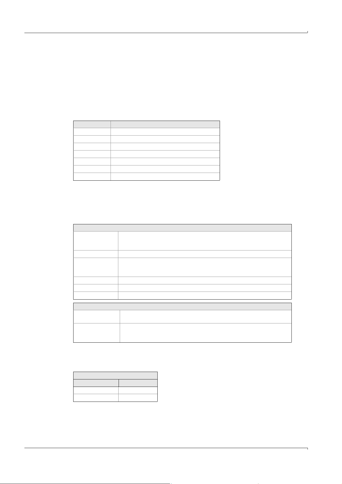
5.7.11.9 Linearization tables
Specialist: System edit: Linearization tables
Linearization tables are used to calculate absorbance into concentration, but also to
calculate digits into analog values or scaling of the flow meter, etc.
The linearization tables are assigned to the components in System edit: Calibration data
and subsequently calculated automatically.
The name of the component that was assigned to the table is stated at the top of the
linearization table.
• Default settings:
Component Linearization table
1Lin. table 1
2Lin. table 2
... Lin. table ...
13 Lin. table 13
14 1:1000 table (for service purposes)
15 Internal throughflow
16 O
2
Modifications to this assignment are free.
Up to 10 pairs of values can be recorded. These are entered in the table where absorbance
is assigned to concentration. The values entered can be set active (mark()) or inactive,
and will correspondingly be used or not used for calculation.
For the default settings for linearization please refer to your system documentation.
Operation
Settings
Lin-TAB Number of table.
The name is identical to the name of the component which this table is assigned to
(in “System edit: Calibration data”).
Fit point Fit point 1..10
Mark ()Mark () = calculate.
If no mark is set, then the pair of values is inserted at the end of the table and not
calculated.
Absorbance Enter measured absorbance
Concentration Enter nominal concentration.
Coefficients Are calculated automatically and entered here
Key assignment::
Shift F5 Display actual value (in Abs. or Conc.).
<ENTER>: Accept displayed value.
F8 Represent linearization curve graphically.
The numerical display corresponds to the pairs of values from the table.
Key 3: Change scales.
Example for a 4 .. 22 mA analog input:
0 .. 4095 Digits correspond to 0 .. 22 mA
Measured value required: 0 at 4 mA and MaxValue at 20 mA
Table entries
Absorbance Concentration
744 0
3724 MaxValue
Subject to change without notice
80 MCS100E Operating Instructions 8009504/VYWA7/V3-1/2018-01 © SICK AG
Page 81
Operation
5.7.11.10 Interference table
Specialist: System edit: Interference table
Interference tables (IF-Tables) are used to correct overlapping spectra.
• Additive interference tables (e.g. for overlapping spectra)
• Multiplicative interference tables (e.g. for dilution effects).
The interference tables are assigned to the components in “System edit: Calibration data”
and automatically calculated - if a mark is set.
4 interference tables per component can be calculated. Default assignment (the
assignment can be changed):
Component IF table
1 IF tables 1..4
2 IF tables 5..8
... IF tables ...
16 IF tables 61..64
The first 3 tables are used preferably for additive IF, the 4
IF.
Additive interference
The spectra of the components are overlapping. The interference can be calculated by
subtraction of the interfering component. For this purpose, the interfering component must
be measured at another place of the spectrum which is free from the influence of further
interferences. This influence is corrected by the additive IF-Table.
th
table is used for multiplicative
Multiplicative interference
The absorbance coefficient of the sample component is influenced by the interfering
component. The interference is compensated by a correction factor. For this purpose, the
interfering component must be measured at another place of the spectrum which is free
from the influence of further interferences. This influence is corrected by the multiplicative
IF-Table.
Settings
IF-Tab. Number of table.
The name is identical to the name of the component which this table is assigned
to (in “System edit: Calibration data”).
IF-Component Component number and name (from Specialist: System edit: Definition of
components) of interference component
IF-Type additive or multiplicative.
IF-Signal Absorbance or concentration, dependent upon what is to be entered.
Fit point Fit point 1..10
Mark ()Mark () = calculate.
If no mark is set, then the pair of values is inserted at the end of the table and not
calculated.
Absorbance Absorbance of sample component. Enter manually.
IF-Component Enter IF-Absorbance/Concentration, depending on what is indicated in
“IF-Signal” (see above)
Key assignment:
Shift F5 Display actual value (in Abs. or Conc., depending on IF Component).
<ENTER>: Accept displayed value.
F8 Represent linearization curve graphically.
Subject to change without notice
The numerical display corresponds to the pairs of values from the table.
Key 3: Change scales.
MCS100E Operating Instructions 8009504/VYWA7/V3-1/2018-01 © SICK AG 81
Page 82

5.7.11.11 Limit values
Alarm high (AH)
Warning high (WH)
Measured value
Warning low (WL)
Alarm low (AL)
Specialist: System edit: Limit values
In this menu the limits that can be interrogated by Specialist: System edit: Zero/Calib/
Purge programs/other programs are defined. The menu is based on “Specialist: System
edit: Results”.
The limits correspond to the units displayed.
There are two lower and two upper limits.
Figure 19 Limit values
Operation
Values falling below or exceeding the limit can be interrogated in Specialist: System edit:
Zero/Calib/Purge/other programs with the variables AH, AL, WH, WL.
There is no hysteresis.
The limits with a mark () are verified.
82 MCS100E Operating Instructions 8009504/VYWA7/V3-1/2018-01 © SICK AG
Subject to change without notice
Page 83
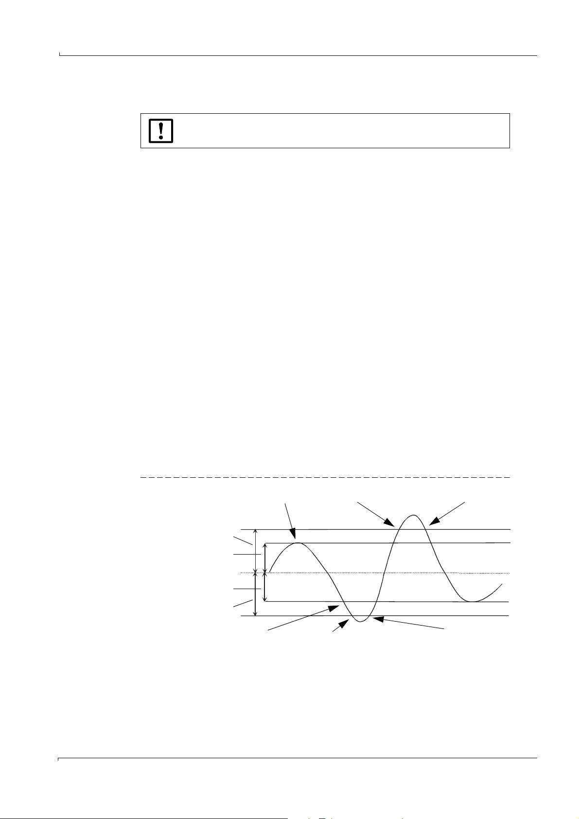
Operation
185 °C
197 °C
190 °C
180 °C
173 °C
Limit
Hysteresis
Nominal (=set value)
Hysteresis
Limit
Heating off
ERROR and ALARM set ERROR reset
Heating on ERROR set ERROR reset
Example: Nominal = 185 °C
Hysteresis = 5 °C
Limit = 12 °C
5.7.11.12 Temperatures and Pressure
Specialist: System edit: Temperatures and Pressure
Changing the temperature affects the measurement operation and can cause
instrument damage.
The temperatures and the pressure correction managed by the system control are defined
in this menu option.
The heating controllers provide 12 bits (0 .. 4095 digits).
For default settings please refer to the status print-out in your system documentation.
Control function of heating controllers
The control function of the heating controllers is as follows:
• Temperature exceeding Nominal+Hysteresis: Heating off
• Temperature lower than Nominal+Hysteresis: Heating on
• Temperature lower than Actual Limit low:
Relay “ERROR” is set.
• If the temperature again exceeds this value, then:
Relay “ERROR” is reset.
• Temperature exceeding Actual value+Limit high:
Relays “ERROR” and ALARM are set.
• If the temperature again falls below this value, then:
Relay “ERROR” is reset; the relay “ALARM”, however, remains set. It must be reset by a
RESET.
The relays ERROR and ALARM are edited in Specialist: System edit: Zero/Calib/Purge
programs/other programs.
For RESET of the alarms, the error message ER 32 (Specialist: System edit: Zero/Calib/
Purge programs/other programs is used.
Figure 20 Switching thresholds of the temperature controllers
Subject to change without notice
MCS100E Operating Instructions 8009504/VYWA7/V3-1/2018-01 © SICK AG 83
Page 84

Settings
No. 1: Temperature of O
2: Temperature of detector
3: Temperature of cell
4: Temperature of detector unit
5: Temperature of heating controller 1, 1st controller, e.g. sample gas pump
6: Temperature of heating controller 1, 2
sensor
2
1
nd
controller, e.g. heating hose
7: Temperature of heating controller 2, 1st controller
8: Temperature of heating controller 2, 2
...
32: Temperature of heating controller 13, 2
nd
controller
nd
controller
33: Printer
The temperatures and the pressure can be interrogated in Specialist: System
edit: Results (as of result 25) and in Specialist: System edit: Zero/Calib/Purge/
other programs (parameter TPA).
Name Name of unit to be controlled. A selection list based on Specialist: System edit:
Results
Actual Actual value in °C resp. mbar (display, only)
Nominal Nominal value in °C resp. mbar (can be entered)
Hyster. Valid for temperature only.
The hysteresis (in °C) defines the switching thresholds of the temperature
controller
Actual > Nominal+Hysteresis => Heating off
Actual < Nominal-Hysteresis => Heating on
Caution: The first 3 heating controllers for O
a hysteresis. Set “0”.
sensor, Detector, Cell, cannot switch
2
Limit low Temperature/pressure difference to lower limit in °C resp. mbar for error relay
Limit high Temperature/pressure difference to upper limit in °C resp. mbar for error and
alarm relays
Offset Temperature = ((Value of Controller) / Factor) + Offset
Value is fixed and cannot be changed.
Factor Scaling factor Temperature = ((Value of Controller) / Factor) + Offset
Value is fixed and cannot be changed.
Relay ERROR Relay number of error relay (inverted possible)
1: Actual > Nominal+Limit high
1: Actual < Nominal-Limit low
0: Limit not exceeded
The relay is interrogated in Specialist: System edit: Zero/Calib/Purge programs/
other programs.
Relay ALARM Relay number of alarm relay (inverted possible)
1: Actual value > nominal value+limit high
Independent of a temperature decrease (external heating controller 5..32), the
relay remains set until RESET is carried out.
The relay is interrogated in Specialist: System edit: Zero/Calib/Purge/other
programs. For RESET the error message ER 32
(Specialist: System edit: Zero/Calib/Purge programs/other programs is used.
1
Only measurement, inputs are not processed
Operation
84 MCS100E Operating Instructions 8009504/VYWA7/V3-1/2018-01 © SICK AG
Subject to change without notice
Page 85

Operation
5.7.11.13 Protocol Definition
Specialist: System edit: Protocol Definition
This menu option is used to make a print-out (protocol) of the stored data.
5 types of protocols can be created and given a name - to ease identification.
Settings
Protocol type (1..5) Selection of one of the 5 protocol types
Name These names are used to ease identification, e.g. at protocol start and stop.
Output to Only “Printer” possible
Filtering Yes:
Cycle [Min]: Output cycle time (in minutes) for printing.
Component selection Selection of the components that are to be printed.
Characters per line Number of characters per line dependent on the paper format. Default setting:
Lines per page Number of lines per page dependent on the paper format. Default setting: 72
Decimal separator Decimal separator Comma or point
Format date Format of date, change with <ENTER>.
Separator of date Separator of date: . or /
Separator of time Separator of time: 14:55:00 or 14-55-00
Separator, column 9: TAB stop
Separator, line 13, 10: CARRIAGE RETURN, LINEFEED
Addition over the cycle time, divided by the number of measured values and
subsequent output of the value.
No:
Actually current value is output
0: Per measurement cycle one value is output.
(The list is derived from the menu Specialist: System edit: Results).
By <ENTER> a list containing the actual components is displayed. If a field is
selected within this list, then a list containing the possible components is
presented.
xxxxx.xx defines the format for display of the measured values, in this example
2 digits following the decimal point; changeable with <ENTER>.
80
Note: The separators of date and time should be different to enable an
evaluation program to find a distinguishing feature.
Separator for individual measured values.
The decimal value of the ASCII character is entered here as these are usually
non-printable characters.
The entry of 2 characters is mandatory.
The decimal value of the ASCII characters is entered here as these are usually
non-printable characters.
File extension for the protocol files is ”.txt”. Protocol files can be edited in the usual table
calculation programs.
The printer protocol settings Main Menu: Printer: Print Archive Protocol Definition and
Specialist: System edit: Protocol Definition are identical.
Subject to change without notice
MCS100E Operating Instructions 8009504/VYWA7/V3-1/2018-01 © SICK AG 85
Page 86
5.7.11.14 Data storage and send to PC
Specialist: System edit: Data storage and send to PC
In this menu, the continuous sending of results and signal outputs and the receipt of the
data are defined.
• If stored to the internal hard disk (Flash disk) storage mode “active”), the program
automatically calculates the length of the files that will be created.
When pressing F1 while you are in one of the main menu fields, the free disk space
remaining is displayed.
• When selecting “PC protocol”, the data are output resp. read-in via the serial interface
(Specialist: Utilities: Service: Environment Configuration : Interfaces). Read-in data will
be shown in the results just like measured values (Parameter S1i at MCS protocol, Ri at
ModBus) (menu Specialist: System edit: Results).
Settings
Results A mark below the result shows when it is chosen.
When selecting Results, a mask appears.
Storage mode Active / not active: Data will be stored / not stored on the internal hard disk
according to the setting.
It can be chosen between “results” and “signal output”.
The “results” are stored according to the setting below: “Length of data file”. When
“signal outputs” is selected, signals are stored each 60 seconds. One file is
generated for each day and each channel. Max. number of days: 1 month, ring buffer
function. Name of the file:
C:\DATALOG\CHxx\xxdd.dat
| | |
| | dd= day
xx=channel number
Flag
“measure”,
“calibration”
Valid for Modbus protocol only.
These are the numbers of the flags indicating “measure” or “calibration” status. The
Modbus master recognizes by the set flag which operating mode is active at present.
Length of data file Valid for “Storage mode “active“” with “results”, only.
Period of time until terminating a measured value file. At the end of the period
defined, the file is closed and a new file is opened. From the length of the file and the
number of results to be stored, the program calculates the size of the file to be
created.
Caution: Upon failure of the computer (e.g. power failure) all data from a
measurement file that is not yet completed will be lost.
Period (Cycle) Cycle time of data storage and transmission to serial interface.
Device address Device address (0..200) for identification for external data acquisition systems.
PC Protocol Modbus RTU (Slave): MCS100E functions like a ModBus Slave.
Modbus RTU (Master): MCS100E functions like a ModBus Master.
MCS only on request: MCS100E sends data to the serial interface on request, only.
MCS100E is continuously ready for receiving data.
MCS on request and in cycles: MCS100E sends data on request and in cycles to the
serial interface. MCS100E is continuously ready for receiving data.
Modbus Definition: The menu that is presented is used for setting the ModBus
parameters. This requires detailed knowledge of the ModBus structure.
During data transmission the address offset is always added to the start register,
resp. only subtracted when data are received, if the start register > address offset.
Modbus Test (Data exchange): This menu is designed for service purposes, only, to
test the ModBus communication. The data sent and received are presented as
hexadecimals.
Operation
When making changes in the selection of the results or in the length of the data
file: Move the cursor once over the field “length of data file” to trigger a new
calculation.
Status bars 1 and 2 are always stored to archive, independent of active/
inactive data storage (
86 MCS100E Operating Instructions 8009504/VYWA7/V3-1/2018-01 © SICK AG
→
p. 44, §5.2).
Subject to change without notice
Page 87

Operation
5.7.11.15 Softkey menu definition
Specialist: System edit: Softkey menu definition
8 softkey menus can be created and totally 64 menu windows can be assigned
correspondingly. When calling-up the menu option, the menu windows are displayed at first.
Switch over to the softkey menus by <ESC>.
Assignment of the Figures to the menus is done in the soft key menus. (
Menu windows
Entries for the 32 menu windows
Menu number Numbering
NAME ON Text, displayed if an action is switched on.
NAME OFF Text, displayed if a switched-on action is going to be switched-off again.
Confirmation Yes: The prompt: “Save changes Y/N?” is displayed.
TOGGLE ON/OFF Yes: It is possible to toggle NAME ON/ NAME OFF (see above).
Enable Flag Flag number for disabling/releasing the menu (Flag set = released)
Activate flag Flag number to display/not display the menu (flag set = menu is displayed)
Set flag Flags that are set (- = reset) if the menu is active.
Sub-menus Sub-menus displayed, if the menu defined here is active.
Position x Vertical position of the sub-menu,
Position y Horizontal position of the sub-menu
Direction Vertical or horizontal size of the sub-menu window
Simulated key Program-internal key assignment
The action activated by the function keys is dependent from the user. Therefore
it is not handled in this manual. For the functions of the function keys please
refer to your system manual.
→
p. 87)
x = line number
y = column
(e.g. key
<F8> simulates key 8)
An existing menu can be copied to a new one by the means of the keys <F5> or
<Shift-F3>.
The question: “Copy from....” appears.
Softkey menus
8 softkey menus are possible:
Pre-assigned menus
0 Main menu
1 Bargraph display
2 Graphical display
3Linearization
4 Graphic outputs
5 - 7 free
Settings
Number Number of the softkey menu (0..7). Open the menu with <ESC>.
Name Name of the softkey menu
Key Key <F3>..<F8> opening the menu window, pre-defined.
Subject to change without notice
No. Number of the menu window, displayed automatically
Name When pressing <ENTER>, a list containing the 32 possible menu windows is
presented. Select requested window with <ENTER>.
Note: If a sub-menu window is open in the graphic, then the graphics display is not updated.
MCS100E Operating Instructions 8009504/VYWA7/V3-1/2018-01 © SICK AG 87
Page 88

5.7.11.16 Mean square fit data
Specialist: System edit: Mean square fit data
Mean square fit data are used to calculate arithmetic functions, e.g. to scale or linearize
analog inputs. The mean square fit data are read-in by CAL in Specialist: System edit:
Results.
Totally, 10 tables can be calculated.
The columns “value X” and “value CAL” can be edited resp. modified alternatively. After
pressing <ENTER>, the fit point (pair of values X and CAL) is sorted into the table according
to the value of the X value.
“Remark” contains explanatory text.
The arithmetic function according to which the fit points are to be calculated, is entered
into the line “Formula”. “Formula” is identical to the formula that can be entered in
Specialist: System edit: Results. Instead of the formula, also the identification of a
calculation from the tables of Specialist: System edit: Results or Specialist: System edit:
Signal output or Specialist: System edit: Graphic output can be entered.
Key assignment:
<F8> Display curves graphically
<Shift–F5> In field X or f(X): Display the calculated formula value.
<ENTER>: Accept displayed value.
Operation
5.7.11.17 Operator's Notebook
Specialist: System edit: Operator's Notebook
The names listed in the operator’s notebook are only used as a memory aid when entering
programs or when printing etc.
88 MCS100E Operating Instructions 8009504/VYWA7/V3-1/2018-01 © SICK AG
Subject to change without notice
Page 89

Operation
5.7.12 System, select for editing
Specialist: System, select for editing
Here, you can select a system (= measurement sequence) for display/editing.
A list of the directories containing the measurement sequences (corresponding to the
existing measurement sequences) is presented. The names of the directories are identical
to the names of the measurement sequences (systems).
The current measurement sequence is not affected and remains active; i.e. you are free to
edit/modify the selected measurement sequence according to your requirements without
interfering with the current measurement.
If, subsequently, you want to activate the modified measurement sequence, then select the
menu “Specialist: System, activate for measurement”.
Entries that are only possible during on-line operation (e.g. zero setting,
calibration, etc.) can, of course, not be made when editing an inactive system
(measurement sequence).
5.7.13 System, create for editing
Specialist: System, create for editing
In this menu option, the active measurement sequence can be copied to a new one with a
new name.
This has no effect on the active measurement sequence and the new measurement
sequence can be edited in Specialist: System, edit (name) and activated by Specialist:
System, activate for measurement, if required.
An entry field is presented for creating a new measurement sequence. You can enter the
new name (max. 8 letters), here. The program will then automatically create a subdirectory
with exactly this name containing the new measurement sequence. Subsequently, all
program files will be contained in this sub-directory.
5.7.14 System, activate for measurement.
Specialist: System, activate for measurement.
This menu is used to activate (= start) another system (= another measurement
sequence). A list of the directories containing the measurement sequences (corresponding
to the existing measurement sequences) is presented. The names of the directories are
identical to the names of the measurement sequences (systems).
Upon selection, a safety prompt is displayed. If your answer to the prompt is positive, then
the new system (the new measurement sequence) becomes active, and the old system is
deactivated automatically.
The system (=measurement sequence) started when calling in the MCS100E
program is derived from the configuration file MCSCONF, menu: Directories
and Files (
→
p. 123, §9.1.3.4).
If you wish another measurement sequence to be activated upon program
start, then you must enter this in the MCSCONF, menu: Directories and Files.
Subject to change without notice
MCS100E Operating Instructions 8009504/VYWA7/V3-1/2018-01 © SICK AG 89
Page 90

5.7.15 Utilities
Specialist: Utilities
5.7.15.1 Show files
Specialist: Utilities: Files, show
The directories and files of the MCS100E are displayed in this menu.
5.7.15.2 Copy files
Specialist: Utilities: Files, copy
This menu is used to copy files on the hard disk of the MCS100E.
After having marked the files (using the space key) and subsequent confirmation with
<ENTER>, you are prompted to enter the “destination path“
for the copy procedure.
Please refer to: Specialist: Utilities: Files, send to PC if you want to copy files to an external
PC
Note: Directories cannot be copied.
Caution: Make sure not to overwrite program files, unintentionally (File name = Directory
name).
5.7.15.3 Erase files
Specialist: Utilities: Files, erase
This menu is used to erase files.
After having marked the files (using the space key) and subsequent confirmation with
<ENTER>, a safety prompt is displayed “Erase all tagged files? (Y/N)”.
Caution: Make sure not to overwrite program files unintentionally (File name = Directory
name).
Operation
5.7.15.4 Send files to an external PC
Specialist: Utilities: Files, send to PC
This menu option is used to send files to an external PC.
In Specialist: Utilities: Service: Environment Configuration : Interfaces, the PC interface
must be configured. The MCS100E measurement program must also be in operation on
the external PC.
The following can be sent:
•System data
•Special data
A menu for selection of the desired data is displayed.
After having marked the files (using the space key) and subsequent confirmation with
<ENTER>, you are prompted to enter the “destination path”
Enter the destination path of the external PC here.
Directories cannot be copied.
Subject to change without notice
90 MCS100E Operating Instructions 8009504/VYWA7/V3-1/2018-01 © SICK AG
Page 91

Operation
5.7.15.5 Receive files from PC
Specialist: Utilities: Files, receive from PC
This menu is used to copy files from an external PC.
In Specialist: Utilities: Service: Environment Configuration: Interfaces, the PC interface
must be configured. The MCS100E measurement program must also be in operation on
the external PC.
After having marked the files (using the space key) and subsequent confirmation with
<ENTER>, you are prompted to enter the “destination path“
Enter the destination path of the external PC here.
Note: Directories cannot be copied.
Caution: Make sure not to overwrite program files unintentionally (File name = Directory
name).
5.7.15.6 Files directory
Specialist: Utilities: Files, directory
Presents the directories and files
This menu cannot be selected (displayed in light grey) when the ModBus
protocol is active.
Subject to change without notice
MCS100E Operating Instructions 8009504/VYWA7/V3-1/2018-01 © SICK AG 91
Page 92
5.7.15.7 Service (TEST)
Specialist: Utilities: Service (TEST)
This program section is only intended for service and test purposes.
5.7.15.7.1 Environment configuration
Specialist: Utilities: Service: Environment configuration
Display Setup
Specialist: Utilities: Service: Environment Configuration : Display Setup
This menu is used to set the display parameters.
Note: The settings are not saved.
Key assignment:
ARROW RIGHT, ARROW LEFT Scroll up/down
ARROW UP, ARROW DOWN Change settings
TEXT file
Specialist: Utilities: Service: Environment Configuration : TEXT file
This menu is used to select the language of the menu texts. The corresponding files are
identified as:
M1Exxx.TXT whereby xxx e.g. DEU (German), ENG (English).
After selecting the language, go to the main menu to activate the language.
Operation
If you select any other than a .TXT file, then texts can no longer be displayed,
and the measurement program ceases to operate.
Then, perform a RESET and restart the software (1.bat).
If the file was not entered correctly in the MCSCONF:
Correct in Directories and Files (→p. 123, §9.1.3.4) and subsequently start
measurement program anew (1.bat)
The language used when calling in the MCS100E program is derived from the
configuration file MCSCONF, menu: Directories and Files (
→
p. 123, §9.1.3.4). If
you wish another language to be activated upon program start, then you must
enter this there.
HELP file
Specialist: Utilities: Service: Environment Configuration : HELP file
This menu is used to select the language of the help texts. The corresponding files are
identified as:
M1Exxx.HLP whereby xxx e.g. DEU (German), ENG (English).
The language used when calling in the MCS100E program is derived from the
configuration file MCSCONF, menu: Directories and Files (
→
p. 123, §9.1.3.4).
If you wish another language to be activated upon program start, then you
must enter this there.
92 MCS100E Operating Instructions 8009504/VYWA7/V3-1/2018-01 © SICK AG
Subject to change without notice
Page 93

Operation
Directories
Specialist: Utilities: Service: Environment Configuration : Directories
The structure of the directories of the program can be modified in this menu. The
directories for
•Program
•Graphic
• Temporary files are interrogated one after the other.
The structure of the directories used when calling in the MCS100E program is
derived from the configuration file MCSCONF, menu: Directories and Files
(
→
p. 123, § 9.1.3.4). If you wish another directory structure to be activated upon
program start, then you must enter this there.
Set Date and Time
Specialist: Utilities: Service: Environment Configuration : Set Date and Time
Date and time can be set in this menu.
When switching over from summer to winter time (time set back by 1 h), the
(saving) times of the data files may become overlapping.
To avoid that duplicate entries affect the evaluation of stored files, stop
data recording (Specialist: System edit: Data storage and send to PC) and
erase those files that were created in the preceding hour.
Interfaces
Specialist: Utilities: Service: Environment Configuration : Interfaces
The hardware default settings of the interfaces are:
COM1 Detector
COM2 I/O module box (opto-interface)
COM3 Pressure/PC/Modem interface (opto-interface)
LPT1 Internal parallel printer interface
• If data are to be sent to an external PC (send data to PC), you must set
- the printer to COM- or LPT1
- the PC to COM3
• If a printer is connected (e.g. for on-line protocol), you must set:
- the printer to COM3 and
- the PC to COM-
• If a modem is connected, you must set :
- the printer to COM or LPT1
- the PC to COM-
Usually pre-assigned:
Data bits 8
Stop bits 1
Parity No
Subject to change without notice
MCS100E Operating Instructions 8009504/VYWA7/V3-1/2018-01 © SICK AG 93
Page 94

Default setting (example) for data to printer:
Detector COM1 9600 Baud
I/O module boxes COM2 9600 Baud (opto-interface)
Printer COM3 4800 Baud (opto-interface)
PC COM–
1
– means: Interface is not assigned
1
9600 Baud
Interrupts
Interrupt assignment is a default setting (dependent on the hardware configuration) and
has to be modified in certain individual cases.
Default setting:
COM IRQ
17
25
1
12
34
43
1
Can also be assigned to LPT 1/2.
If used by COMi: LPTi disable
2
Reserved for I/O module box
Operation
94 MCS100E Operating Instructions 8009504/VYWA7/V3-1/2018-01 © SICK AG
Subject to change without notice
Page 95

Operation
5.7.15.7.2 Control Detector unit
Specialist: Utilities: Service: Control Detector unit
This menu option contains the display and calibration of the components activated in
“Specialist: System edit: Definition of components” as well as a variety of tests.
Settings
REF
Meas
ABS raw Display of absorbance, not corrected.
ABS add Display of additively corrected absorbance.
ABSORB. Display of completely corrected absorbance.
CONCENT Calculated concentration
CALIBRATION Predefined calibration value
Calibration fac-
tor
ZERO SET Actual value is set to “Zero“
Tst 0 Terminate all switched-on tests.
Tst 1 LPM40 send disable
Tst 2 LPM40 send enable
Tst 3 LPM40 restart
Tst 4 Test signal on. Instead of the detector signal a testsignal is enabled for the pre-
Tst 5 Test signal off.
Tst 6 Determine amplification
Tst 7 Send data to LPM40
Tst 8 No synchronization
Tst 9 .. Tst 15 Not used
Status Detector
0OK
8 Power failure on LPM40
Energy of the reference resp. measurement signal in counts, dependent of the gain
factor (i.e. counts increase with the gain factor).
Upon <ENTER>, the calibration factor is calculated is such a way that the CONCENT.
equals the value pre-defined in CALIBRATION.
amplifier.
Disables the test signal enabled in test 4.
At the bottom, left, the measurement cycle time and the component that is being
measured, are displayed.
5.7.15.7.3 Dialogue Detector unit
Specialist: Utilities: Service: Dialogue Detector unit
Dialogue with detector unit: Only for service purposes
ASCII - Hex - switch-over: ALT H
Echo ON/OFF: ALT E
Menu exit: F2 or ALT X
5.7.15.7.4 Dialogue heat control
Specialist: Utilities: Service: Dialogue heat control
Dialogue with heat control: Only for service purposes
ASCII - Hex - switch-over: ALT H
Echo ON/OFF: ALT E
Menu exit: F2 or ALT X
Subject to change without notice
MCS100E Operating Instructions 8009504/VYWA7/V3-1/2018-01 © SICK AG 95
Page 96

5.7.15.7.5 Dialogue external PC
Specialist: Utilities: Service: Dialogue external PC
Dialogue with external PC: Only for service purposes
ASCII - Hex - switch-over: ALT H
Echo ON/OFF: ALT E
Menu exit: F2 or ALT X
5.7.15.7.6 Initialisation of I/O modules
Specialist: Utilities: Service: Initialisation of I/O modules
Settings
Progr. existing I/O
modules
All addresses of existing and active boards of the I/O module boxes are
displayed and can be changed.
Progr. new I/O modules All addresses of existing and active boards of the I/O module boxes are
displayed and – for new boards – addresses can be added.
For analog input, analog output, and heating controller:
While choosing an address, the read values are displayed (ACTUAL
parameters) as well as recommended default values (NOMINAL parameters).
The nominal parameters can be altered and programmed (programming will
be prompted while leaving the menu).
Function DO
Gain -32768...32767 Default = 0 (K = 1.0)
Offset -4096...4095 Default = -102
Gain/Offset Correction ON/OFF Default = ON
HC mode H1, T1, B1
Write protection ON/OFF
Search existing
All I/O module boxes are searched and the addresses found are displayed.
I/O modules
1
Only for function HC
Possible entry Meaning
Digital output
DI
AO
AI
HC
1
1
Digital input
Analog output
Analog input
Heating controller
Default = H1
Default = ON
Operation
You can assign an address to one board at a time, only. All other boards must
be switched to the “not active” condition. There is a corresponding message in
the menu.
For assigning addresses to the boards→ “I/O Module Box, User's Manual“
5.7.15.7.7 STOP, START measure
Specialist: Utilities: Service: STOP, START measure
Only for service purposes
Upon measurement “STOP”, all interfaces (e.g. internal LPM40, I/O module boxes) are
deactivated.
Upon measurement “START”, all interfaces are re-initialized and the measurement
sequence is started.
96 MCS100E Operating Instructions 8009504/VYWA7/V3-1/2018-01 © SICK AG
Subject to change without notice
Page 97

Operation
5.7.15.7.8 Measuring signal settings
Specialist: Utilities: Service: Measuring signal settings
In this menu the ZERO and calibration data are set to “first” value (the subsequent drift
calculations of zero settings resp. calibrations will be based on these values).
ZERO: Set ACTUAL to FIRST (of all components)
CALIBRATION: Set ACTUAL to FIRST (of all components)
Set pre-amplifier level: Automatic adaptation of amplifier
The actions are started by <ENTER> in the corresponding line. A safety prompt will be
displayed.
These actions are recommended to be performed after a service.
5.7.15.7.9 Display numerical values
Specialist: Utilities: Service: Display numerical values
This menu shows the calculated results, analog outputs and curves in numerical values.
Settings
Channel
Name Name of component
Value Value calculated
Unit Unit of component
R = Result
A = Analog outputs
K = Curves
5.7.15.8 Display, digital status
Specialist: Utilities: Service: Display, digital status
This menu shows the digital status (digital inputs/outputs, relays, flags, timer) of
MCS100E.
Settings
0 Status “not set”
1 Status “set”
Subject to change without notice
MCS100E Operating Instructions 8009504/VYWA7/V3-1/2018-01 © SICK AG 97
Page 98

Operation
98 MCS100E Operating Instructions 8009504/VYWA7/V3-1/2018-01 © SICK AG
Subject to change without notice
Page 99

Decommissioning
MCS100E
6 Decommissioning
Switch off
Disassembly
Storage
Disposal
Subject to change without notice
MCS100E Operating Instructions 8009504/VYWA7/V3-1/2018-01 © SICK AG 99
Page 100
6.1 Switch off
WARNING: Hazard resulting from substances remaining in the cell
When switching off the gas supply and depending on the sample gas
composition, it is possible that toxic or corrosive gases remain in the cell and
the connected pipes. If necessary:
Purge the cell and the connected pipes for at least 1 h with inert gas (e.g.:
N
Take suitable protective measures (e.g. working under a vent, wearing
suitable protective clothes).
Decontaminate the cell.
1 Purge the MCS100E with inert gas for min. 1 h.
2 Exit the measurement program (
3 If necessary, unplug voltage plug resp. disconnect MCS100E from power supply at all
poles.
6.2 Disassembly
Unscrew the sample gas lines.
WARNING: Hazard by splashing acids
When hose lines are removed there is a hazard of splashing by acids which
could still be in the line.
If hose lines are blocked, the acids can be under pressure.
Take suitable safety measures.
Decommissioning
).
2
→
p. 46, §5.4.2).
To remove the fiber optics pull at the connector, only.
Unscrew the MCS100E and transport with care
Protect the MCS100E from shock and vibrations.
6.3 Storage
Storage conditions
•Indoors.
• Ambient temperature: -10 - +60 °C.
Relative humidity: Max. 80% (without condensation)
6.4 Disposal
The following subassemblies could contain substances that have to be disposed of
separately:
• Electronics: Capacitors, rechargeable batteries, batteries.
• Display: Liquid of LC display
• Sample gas filter: Sample gas filters could be contaminated by pollutants.
Observe the relevant local conditions for the disposal of industrial waste.
Subject to change without notice
100 MCS100E Operating Instructions 8009504/VYWA7/V3-1/2018-01 © SICK AG
 Loading...