

Page 1

O P E R A T I N G I N S T R U C T I O N S
MAX
Linear encoder
Page 2

Product described
MAX linear encoder
Manufacturer
SICK AG
Erwin-Sick-Str. 1
79183 Waldkirch
Germany
Legal information
This work is protected by copyright. Any rights derived from the copyright shall be
reserved for SICK AG. Reproduction of this document or parts of this document is only
permissible within the limits of the legal determination of Copyright Law. Any modifica‐
tion, abridgment or translation of this document is prohibited without the express writ‐
ten permission of SICK AG.
The trademarks stated in this document are the property of their respective owner.
© SICK AG. All rights reserved.
Original document
This document is an original document of SICK AG.
2
O PE R AT I NG IN S TR U CT I ON S | MA X 8022793/ZXZ4/2018-07-24 | SICK
Subject to change without notice
Page 3

Contents
1 About this document........................................................................ 6
1.1 Purpose of this document........................................................................ 6
1.2 Target audience........................................................................................ 6
1.3 Further information................................................................................... 6
1.4 Symbols and document conventions...................................................... 6
1.4.1 Warning levels and signal words............................................. 6
1.4.2 Information symbols................................................................ 6
2 Safety information............................................................................ 7
2.1 General notes............................................................................................ 7
2.2 Intended use............................................................................................. 7
2.2.1 Purpose of the device.............................................................. 7
2.3 Responsibility of user............................................................................... 7
3 Product description........................................................................... 9
3.1 Device variants......................................................................................... 9
3.2 Product identification............................................................................... 9
3.3 Construction and function........................................................................ 10
4 Mounting............................................................................................. 12
4.1 Preparation before installing the encoder.............................................. 12
4.1.1 Installation cavity for the linear encoder................................ 12
4.1.2 Installation cavity for the piston and piston rod.................... 13
4.1.3 Insertion chamfer.................................................................... 14
4.1.4 Bore hole for the retaining screw............................................ 14
4.1.5 Bore hole for the electrical connection.................................. 15
4.1.6 Installation cavity for the position magnet............................. 17
4.2 Installing the position magnet................................................................. 17
4.3 Installing the encoder............................................................................... 18
4.3.1 Positioning the O-ring and support ring................................. 18
4.3.2 Insertion in the cylinder........................................................... 19
4.3.3 Installation with an M12 connector system........................... 20
4.3.4 Installation with a cable connector and cable gland............. 21
4.4 Install the retaining screw........................................................................ 22
4.5 Cylinder handling after encoder installation........................................... 22
4.5.1 Washing and drying the cylinder............................................. 22
4.5.2 Electrostatic painting of the cylinder...................................... 23
4.5.3 Mounting the cylinder on mobile hydraulic machines.......... 23
4.5.4 Electrical and electrostatic interference................................ 23
5 Electrical installation........................................................................ 25
5.1 Electrical connection................................................................................ 25
5.1.1 Connection diagram, pin assignment for 4-pin M12 male
connector................................................................................. 25
CONTENTS
8022793/ZXZ4/2018-07-24 | SICK O PE R AT I NG IN S TR U CT I ON S | MA X
3
Subject to change without notice
Page 4

5.1.2 Cable connection diagram...................................................... 25
5.1.3 Connection diagram, pin assignment for 5-pin M12 male
connector................................................................................. 25
5.1.4 Connection sequence.............................................................. 26
5.2 Connection diagram for vehicle electronics............................................ 26
6 Commissioning.................................................................................. 27
6.1 Putting the encoder into operation.......................................................... 27
6.2 Select a suitable fuse............................................................................... 27
6.3 Set up the filter wiring - analog................................................................ 27
6.4 Power-up and output signal in the event of a fault................................. 27
6.5 Bus termination - digital........................................................................... 28
6.6 Tolerance considerations for the set point............................................. 28
6.7 CAN bus protocols.................................................................................... 29
6.8 Communication objects........................................................................... 30
6.8.1 CANopen................................................................................... 30
6.8.2 SAE J1939................................................................................ 31
6.9 Configuration and system startup........................................................... 31
6.9.1 Configuring CANopen.............................................................. 31
6.9.2 Configuring SAE J1939........................................................... 33
6.9.3 System startup for CANopen................................................... 34
6.9.4 System startup for SAE J1939................................................ 34
6.9.5 Setting CANopen operating parameters................................ 34
6.9.6 Setting SAE J1939 operating parameters............................. 36
6.9.7 CANopen encoder data during operation............................... 36
6.9.8 SAE J1939 encoder data during operation............................ 36
6.9.9 CANopen error messages....................................................... 36
6.9.10 SAE J1939 error messages.................................................... 37
7 Maintenance...................................................................................... 38
7.1 Error table................................................................................................. 38
7.2 Checking the functioning of the encoder................................................ 38
7.3 Repairs...................................................................................................... 39
7.4 Testing and programming........................................................................ 40
8 Transport and storage....................................................................... 41
8.1 Transport and storage conditions............................................................ 41
9 Decommissioning............................................................................. 42
9.1 Dismantling............................................................................................... 42
9.2 Disposal..................................................................................................... 42
10 Technical data.................................................................................... 43
10.1 MAX Analog/PWM..................................................................................... 43
10.2 MAX Digital CANopen / SAE J1939......................................................... 46
10.3 Encoder dimensions................................................................................. 48
10.4 Position magnet dimensions.................................................................... 49
CONTENTS
4
O PE R AT I NG IN S TR U CT I ON S | MA X 8022793/ZXZ4/2018-07-24 | SICK
Subject to change without notice
Page 5

10.5 M12 flange dimensions........................................................................... 50
11 Annex.................................................................................................. 51
11.1 Accessories............................................................................................... 51
11.2 Spare parts............................................................................................... 53
11.3 CE Declaration of Conformity................................................................... 55
CONTENTS
8022793/ZXZ4/2018-07-24 | SICK O PE R AT I NG IN S TR U CT I ON S | MA X
5
Subject to change without notice
Page 6

1 About this document
1.1 Purpose of this document
In the following instructions, the MAX linear encoder is referred to simply as “encoder”
or “device”.
These operating instructions describe:
•
Device components
•
Mechanical preparation of the device
•
Electrical preparation of the device
•
Necessary maintenance work for safe operation
1.2 Target audience
This document is intended for technicians (persons with technical expertise) tasked
with installing and maintaining the device.
These technicians must be trained on the device.
Only trained electricians are permitted to carry out work on the electrical system or
electrical assemblies.
1.3 Further information
•
MAX quickstart
•
Technical information - interface description
MAX product pages
•
www.sick.com/MAX48
•
www.sick.com/MAX30
1.4 Symbols and document conventions
1.4.1 Warning levels and signal words
Important
Hazard which could result in property damage.
Note
Tips
1.4.2 Information symbols
Table 1: Information symbols
Icon Meaning
Important technical information for this product
Important information about electrical or electronic functions
1 ABOUT THIS DOCUMENT
6
O PE R AT I NG IN S TR U CT I ON S | MA X 8022793/ZXZ4/2018-07-24 | SICK
Subject to change without notice
Page 7

2 Safety information
2.1 General notes
Should persons be placed at risk, or operating equipment potentially be damaged in
the event of a malfunction or failure of the device, this must be prevented by means of
suitable protective devices, e. g., emergency shutdown systems.
If the device is not functioning correctly, it must be taken out of operation and secured
against unauthorized operation.
To guarantee proper operation of the device, please observe the following:
•
Protect the device against mechanical stress during installation
•
Do not open the device
•
Connect the device with the correct polarity, supply voltage, and control pulses
•
Observe the permissible operating and ambient conditions for the device
•
Regularly check the device for correct operation and document the results
2.2 Intended use
2.2.1 Purpose of the device
The MAX linear encoder is designed for position measurements in mobile hydraulic
applications and therefore can be used to control the hydraulic components of con‐
struction machinery; e.g., in hydraulic cylinders. The rugged housing offers optimum
protection against dust, climatic influences, vibrations, surrounding media, as well as
electrical and magnetic fields.
The device is an accessory and must be connected to a suitable electronic control unit.
2.3 Responsibility of user
Designated users
see "Target audience", page 6.
Correct project planning
•
This document assumes that appropriate project planning has been carried out
before delivery of the device (e.g., based on the SICK application questionnaire),
and the device is in the required delivery state based on that planning (see sup‐
plied system documentation).
w
If you are not certain whether the device corresponds to the state defined
during project planning or in the supplied system documentation, please con‐
tact SICK Customer Service.
Special local conditions
In addition to the instructions in this Technical Information, follow all local laws, techni‐
cal rules and company-internal operating directives applicable at the respective device
installation location.
Read the operating instructions
b
Read and follow the operating instructions in this document
b
Follow all safety notes
b
If there is anything you do not understand, please contact SICK Customer Service
SAFETY INFORMATION 2
8022793/ZXZ4/2018-07-24 | SICK O PE R AT I NG IN S TR U CT I ON S | MA X
7
Subject to change without notice
Page 8

Retention of documents
These operating instructions:
b
Must be made available for reference.
b
Must be conveyed to new owners.
2 SAFETY INFORMATION
8
O PE R AT I NG IN S TR U CT I ON S | MA X 8022793/ZXZ4/2018-07-24 | SICK
Subject to change without notice
Page 9

3 Product description
3.1 Device variants
The device is available in the following variants:
•
M12 male connector (4-pin or 5-pin) or 3-wire PUR cable
Output signals
•
Analog (current, voltage)
•
PWM
•
Digital (CANopen, SAE J1939)
3.2 Product identification
Type code
Table 2: Type code (example)
1 2 3 4 5 6 7 8 9 10 11 12 13 14 15 16 17 18
M T X 4 8 N - 1 1 R 1 0 T T
Table 3: Type code Explanation
Position Meaning Description
1 Series M = Mobile
2 Technology A = Magnetostrictive
3 Installation type X = Integrated (hydraulic cylinder)
4 Size 48 = MAX48 diameter
30 = MAX30 diameter
5
6 Version N = Non-Safety
7 Place holder -
8 Diameter
Pressure pipe
1 = 10 mm / 30 mm damping
2 = 10 mm / 36 mm damping
3 = 10 mm / 63 mm damping
7 = 7 mm / 30 mm damping
8 = 7 mm / 36 mm damping
9 = 7 mm / 63 mm damping
9 Voltage supply 1 = 12 VDC
2 = 24 VDC
10 Electrical
Interface
V = Voltage
A = Current
C = Digital CANopen (250 kbit)
J = Digital SAE J1939 (250 kbit)
P = pulse-width modulation, 5 V signal
11 Signal output 10 = current (4 ... 20 mA)
10 = voltage (0.50 ... 4.50 V)
21 = voltage (4.75 ... 0.25 V)
7F = CANopen (node ID 7F Hex)
JD = SAE J1939 (source address JD Hex)
B = pulse width (10 ... 90%)
D = frequency (250 Hz)
12
PRODUCT DESCRIPTION 3
8022793/ZXZ4/2018-07-24 | SICK O PE R AT I NG IN S TR U CT I ON S | MA X
9
Subject to change without notice
Page 10
Position Meaning Description
13 Connection type A = M12 4-pin analog / PWM
(1 = VDC; 2 = n.c.; 3 = GND; 4 = SIG)
B = M12 4-pin analog / PWM
(1 = VDC; 2 = SIG; 3 = GND; 4 = n.c.)
M= M12 4-pin analog
(1 = n.c.; 2 = VDC; 3 = GND; 4 = SIG)
K = analog cable connection / PWM 3-wire cable
C = M12 5-pin digital
(1 = n.c.; 2 = VDC; 3 = GND; 4 = CAN_HI; 5 = CAN_LO)
D = M12 5-pin digital
(1 = VDC; 2 = n.c.; 3 = GND; 4 = CAN_HI; 5 = CAN_LO)
14 Connector length A = 60 mm M12
E = 100 mm M12
15 Measuring range
Position measurement
in 1 mm steps
e.g., 0300 = 50 ... 300 mm
16
17
18
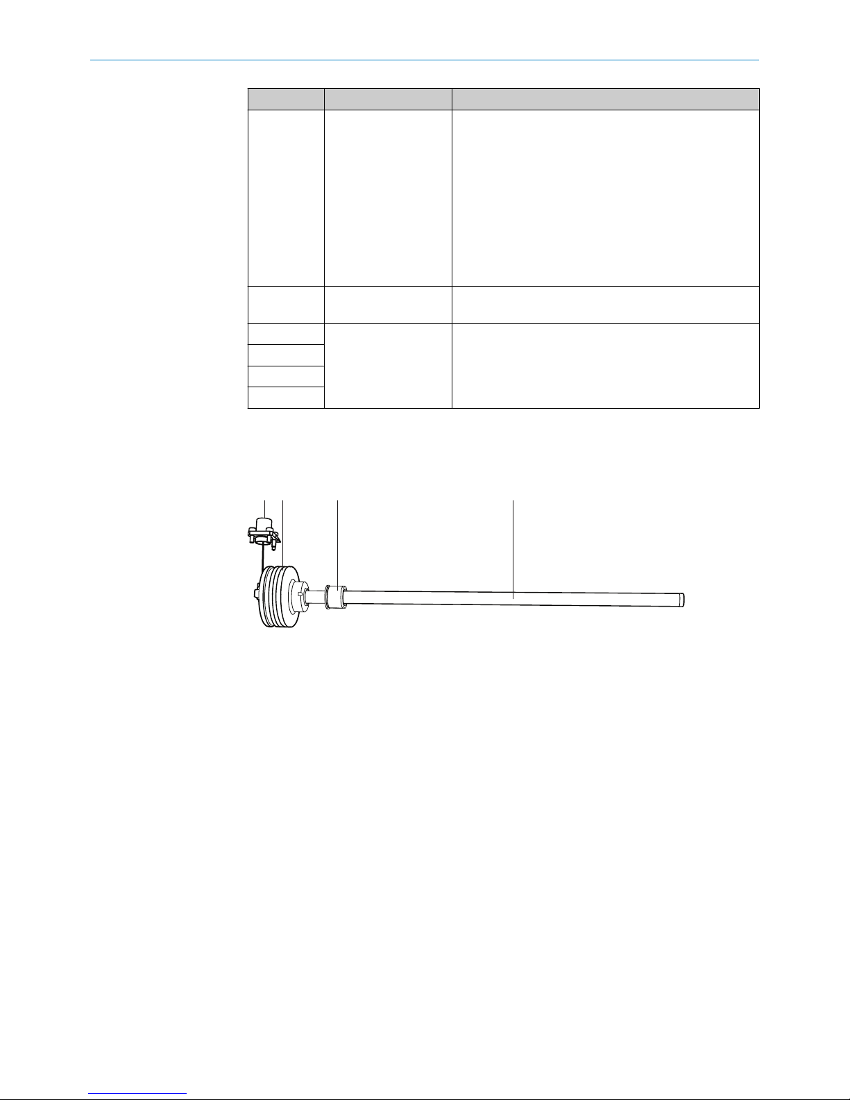
3.3 Construction and function
Construction of the device
1
2 3 4
Figure 1: MAX design
1
M12 connector system
2
Protective housing (electronics)
3
Position magnet
4
Pressure pipe
Connector system:
The M12 connector system requires very little time to attach. It is suitable for applica‐
tions in harsh environments up to IP69K (when using a suitable mating connector).
Protective housing (electronics):
The housing is designed to be installed in a hydraulic cylinder and protects the electron‐
ics against external influences.
Position magnet:
The position magnet is the only moving component in the measuring device when
installed in the piston. The position magnet is located inside the piston and moves over
the pressure pipe without contacting it. The magnet field that is produced during this
process defines the current position of the piston.
Pressure pipe:
The pressure pipe is a pressure-resistant structure that is immersed into the cylinder
piston rod. It contains the hermetically protected magnetostrictive sensing element.
3
PRODUCT DESCRIPTION
10
O PE R AT I NG IN S TR U CT I ON S | MA X 8022793/ZXZ4/2018-07-24 | SICK
Subject to change without notice
Page 11
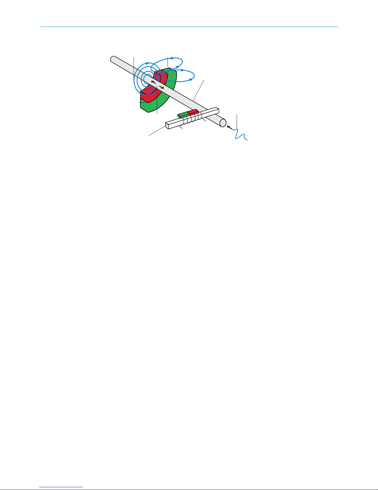
Principle of operation
21
3
4
5
6
7
Figure 2: Schematic of the magnetostrictive measurement principle
1
Magnet field of the current pulse
2
Magnet field of the position magnet
3
Magnetostrictive sensor component
4
Current pulse
5
Sound wave converter
6
Structure-borne sound wave
7
Position magnet
The device operates on the magnetostrictive measurement principle that records the
actual path of a position magnet:
The radial magnet field (1) generated by the current pulse (4) interacts with the magnet
field (2) of the position magnet (7).
As a result of the interaction of the two magnet fields, a wave (ultrasonic) (6) is pro‐
duced in the magnetostrictive device component (3). This travels to the converter (5),
and the electronics produce an electrical output signal.
The time interval between the current pulse and the detection of the structure-borne
sound wave is measured, thereby enabling the precise position of the magnet – which
changes as the cylinder moves – to be determined. As this measurement principle does
not require a reference point, no recalibration is necessary for this type of device.
The device is also maintenance-free as a result of the non-contact measurement.
PRODUCT DESCRIPTION
3
8022793/ZXZ4/2018-07-24 | SICK O PE R AT I NG IN S TR U CT I ON S | MA X
11
Subject to change without notice
Page 12
4 Mounting
4.1 Preparation before installing the encoder
4.1.1 Installation cavity for the linear encoder
The method of installation depends on the cylinder design. Generally, the sensor is
installed from the piston rod side. It is also possible to install the sensor from the head
side of the cylinder.
The encoder dimensions are listed in the technical specifications: see "Encoder dimen‐
sions", page 48.
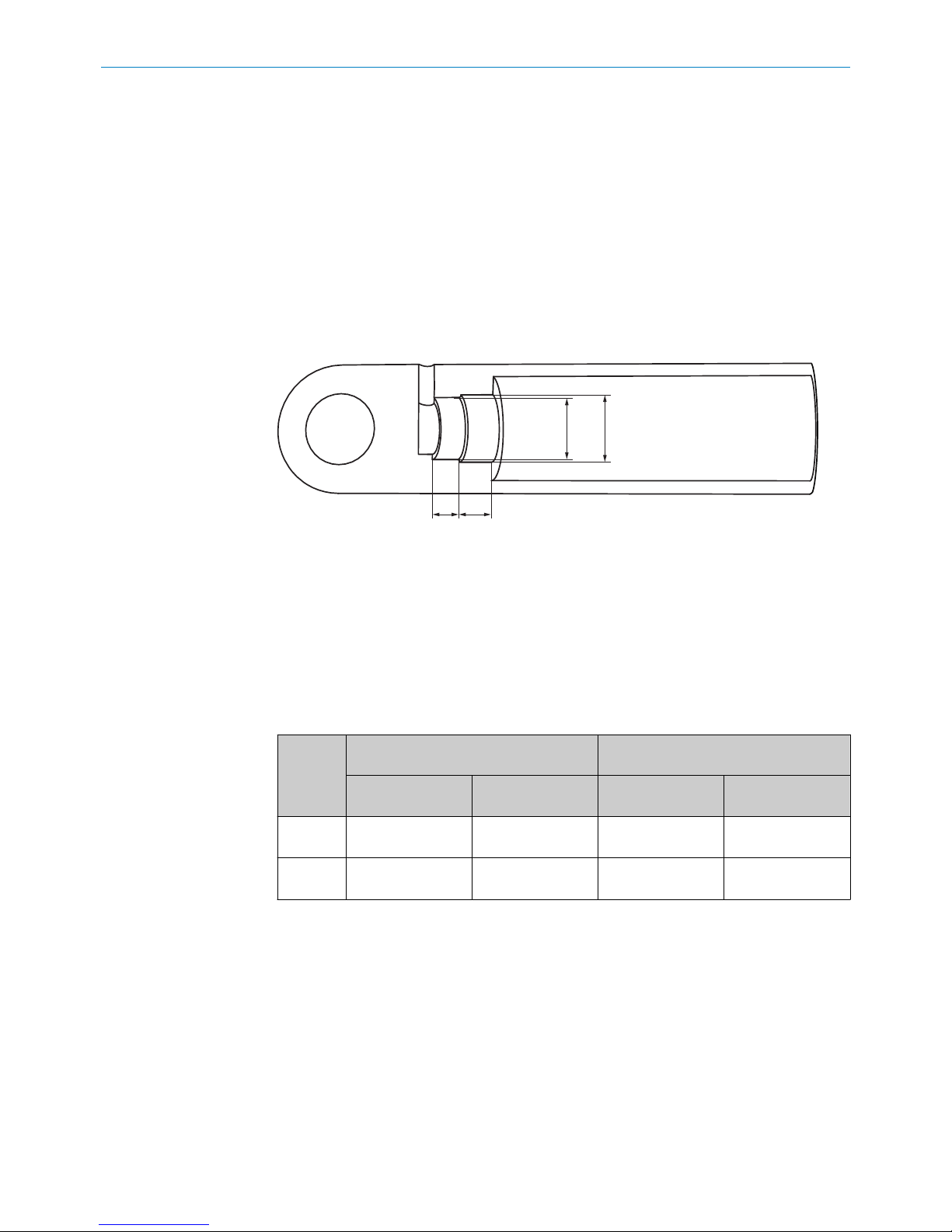
Fit dimensions and tolerances
4 2
3 1
Figure 3: Encoder installation cavity dimensions
1
Diameter for housing bore hole
2
Depth for housing bore hole
3
Installation cavity diameter for electrical connection
4
Installation cavity depth for electrical connection
b
Prepare an installation cavity for the encoder according to the following dimen‐
sions.
Table 4: Installation cavity for the housing and electrical connection
Type Installation cavity for housing Installation cavity for electrical connec‐
tion
1
Ø
2
Depth [D]
3
Ø min. ... Ø max.4Depth [d]
MAX48 48H8 21.2 mm + 0.2 d > 32.5 mm
d < 40 mm
≥ 10 mm
MAX30 31H8 22.7 mm +0.2 d > 26 mm
d < 28 mm
≥ 10 mm
Mean roughness value of the surface: Ra < 0.8 mm.
4
MOUNTING
12
O PE R AT I NG IN S TR U CT I ON S | MA X 8022793/ZXZ4/2018-07-24 | SICK
Subject to change without notice
Page 13
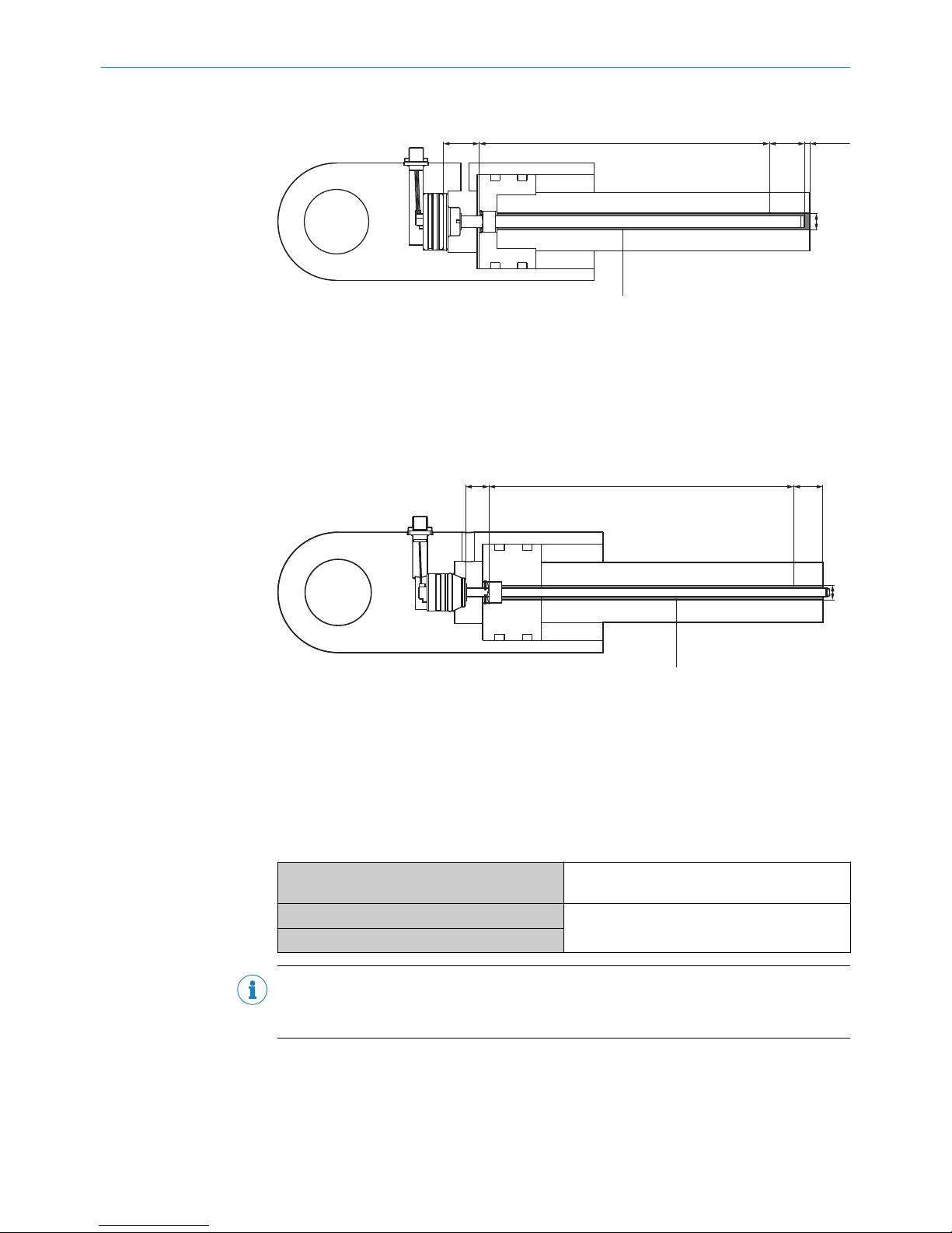
4.1.2 Installation cavity for the piston and piston rod
4
1
2
3
5
>3 mm
(0.12)
Figure 4: Encoder installed in the hydraulic cylinder – MAX48
1
Null zone
2
Measuring range
3
Damping
4
Diameter of the pressure pipe
5
Diameter of the piston rod bore hole
1 2 3
4
5
Figure 5: Encoder installed in the hydraulic cylinder – MAX30
1
Null zone
2
Measuring range
3
Damping
4
Diameter of the pressure pipe
5
Diameter of the piston rod bore hole
Table 5: Bore hole depth for the piston rod
1 = Null zone
MAX48: 30 mm
MAX30: 19.5 mm
2 = Measuring range
as per the applicable data sheet and selected
device variant
3 = Damping
NOTE
The total bore hole depth comprises the measuring range (2), the damping (3), and an
addition distance of 3 mm to the pressure pipe.
b
Prepare an installation cavity for the piston rod in accordance with the following
dimensions.
MOUNTING
4
8022793/ZXZ4/2018-07-24 | SICK O PE R AT I NG IN S TR U CT I ON S | MA X
13
Subject to change without notice
Page 14
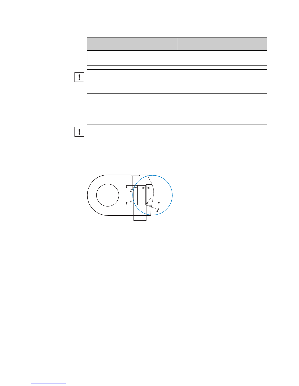
Table 6: Bore hole diameter for the piston rod
4
Ø Pressure pipe
5
Ø Bore hole in the piston rod
Ø 7 mm Ø 10 mm
Ø 10 mm Ø 12 mm / 13 mm
NOTICE
Ensure a consistent bore hole diameter of at least 12 mm.
Take into consideration the design and loading of the piston rod.
4.1.3 Insertion chamfer
To ensure proper and secure installation of the device in the cylinder, a insertion cham‐
fer must be provided.
NOTICE
Risk of damage to the device during installation
The device can be damaged by any sharp edges present at the transition from the cylin‐
der bore hole to the insertion chamfer on the O-ring.
b
Prepare an insertion chamfer with a radius of 0.6 mm at the end of the cylinder
bore hole.
d
21.2 +0.2
(0.83 +0.01)
min. 10
(0.39)
1.5 (0.06)
20°
R 0.6
(0.06)
Ø MAX
Figure 6: Insertion chamfer
4.1.4 Bore hole for the retaining screw
b
Prepare a bore hole for the retaining screw in accordance with the following dimen‐
sions.
4 MOUNTING
14
O PE R AT I NG IN S TR U CT I ON S | MA X 8022793/ZXZ4/2018-07-24 | SICK
Subject to change without notice
Page 15
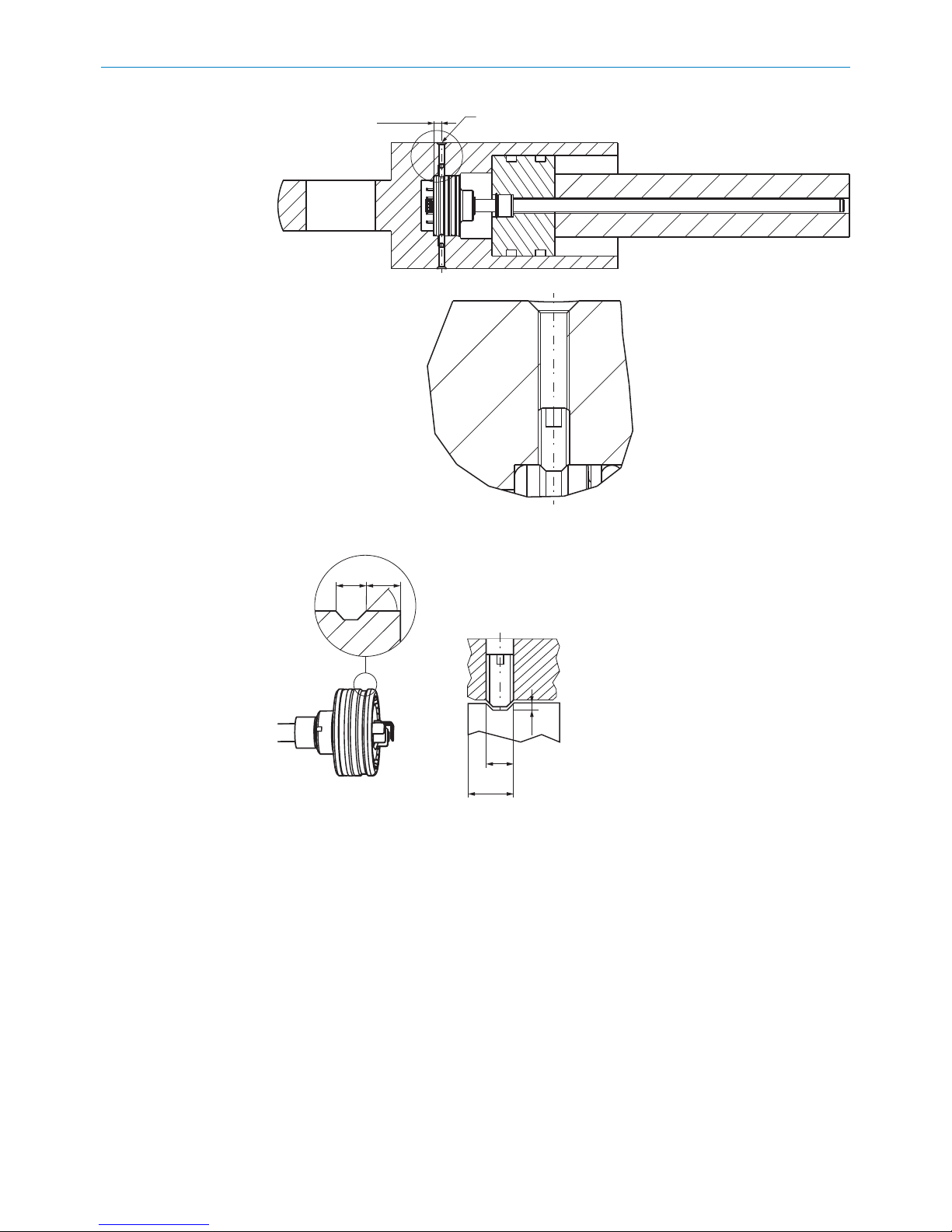
6.25 ±0.1
(0.25)
M5 x 8
Figure 7: Installation cavity for the retaining screw
45°
4
(0.16)
4.5
(0.18)
8.5
(0.33)
1
(0.04)
4.5
(0.18)
Figure 8: Retaining screw on the encoder housing
Permissible tightening torque for fastening screw: 0.5 Nm ... 1.0 Nm (taking into
account the maximum force on the housing surface).
4.1.5 Bore hole for the electrical connection
M12 flange
b
Prepare an installation cavity for the connector system and flange plate in accor‐
dance with the following dimensions.
MOUNTING 4
8022793/ZXZ4/2018-07-24 | SICK O PE R AT I NG IN S TR U CT I ON S | MA X
15
Subject to change without notice
Page 16
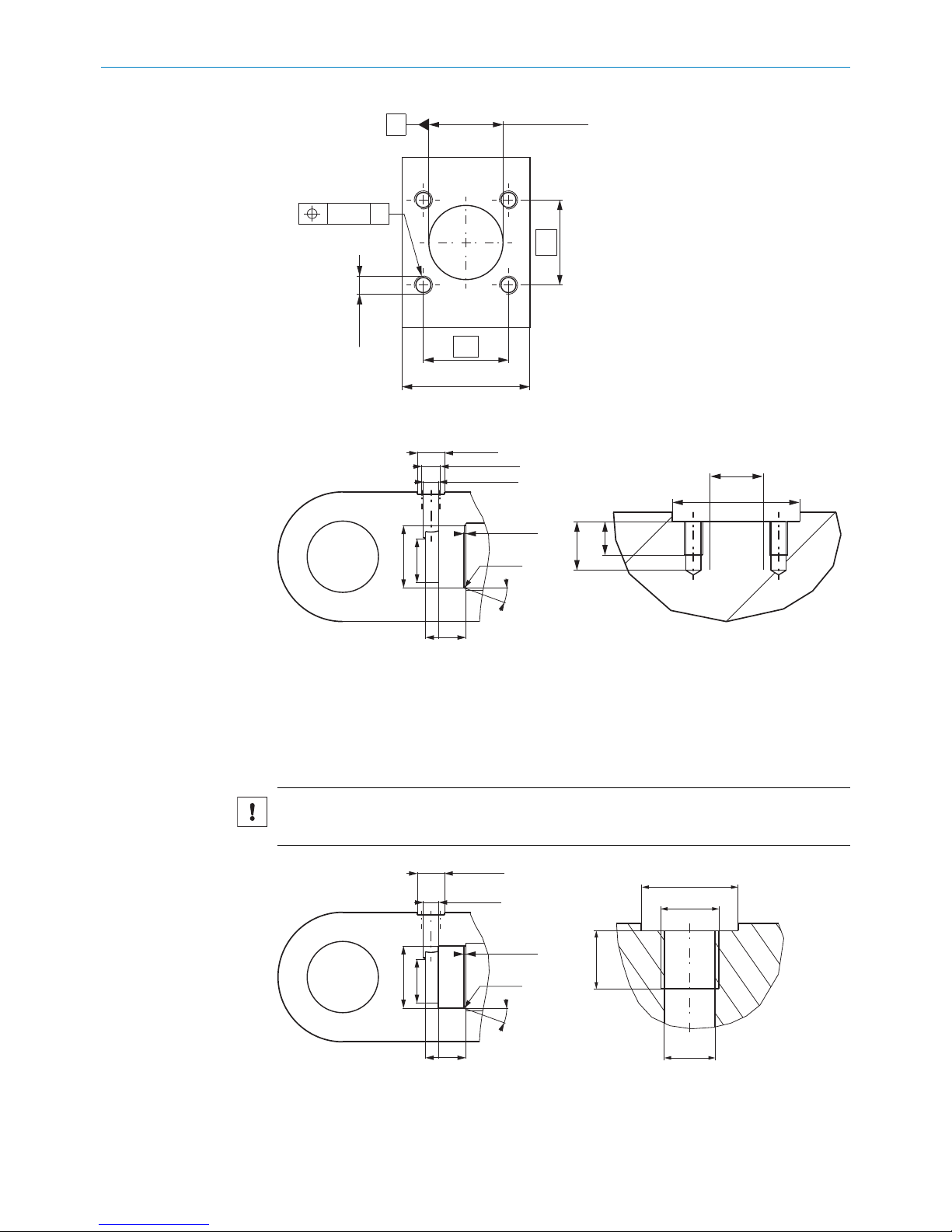
14
14
21 ±0.2
(0.38 ±0.01)
Ø 12.2 ±0.1
(0.48)
A
AØ 0.1
4x
4 x M3
Figure 9: Dimensions of the flange plate bore holes
21 (0.83)
14 (0.55)
M12 x 1.5
(0.06)
d
min. 10
(0.39)
1.5 (0.06)
20°
R 0.6
(0.06)
8
(0.31)
5.5
(0.22)
21
(0.83)
Ø 12.2
(0.48)
Ø MAX
T
Figure 10: Dimensions of the connector system bore hole
Cable gland
b
Prepare an installation cavity for the cable gland according to the following dimen‐
sions.
NOTICE
b
Prepare a counterbore to suit the cable gland, see figure 40, page 52.
Ø 21 (0.83)
M 12 x 1.5
Ø 10.5
(0.41)
12
(0.47)
Ø 21 (0.83)
M 12 x 1.5
d
min. 10
(0.39)
1.5 (0.06)
20°
R 0.6
(0.06)
Ø MAX
T
Figure 11: Dimensions of the cable gland bore hole
4 MOUNTING
16
O PE R AT I NG IN S TR U CT I ON S | MA X 8022793/ZXZ4/2018-07-24 | SICK
Subject to change without notice
Page 17
4.1.6 Installation cavity for the position magnet
b
Prepare an installation cavity for the position magnet in accordance with the fol‐
lowing dimensions.
1.5
(0.06)
1.1 H13
(0.04)
13.2 +0.1
(0.52)
Ø 17.5 +0.1
(0.69)
Ø 19 H11
(0.75)
Ø 12
(0.45)
Figure 12: Dimensions of the position magnet installation cavity
4.2 Installing the position magnet
Table 7: Position magnet installation dimensions
1 Corrugated spring washer
see figure 37, page 51
2 Position magnet
17.4 x 12.0 x 10.6 mm
3 Circlip
DIN 472 - 18x1, alternatively see figure 39,
page 52
Diameter of the position magnet bore hole 17.5 + 0.1 mm
Depth of the position magnet bore hole 13.2 + 0.1 mm
Sequence of work steps:
NOTICE
b
Ensure that the retaining ring and the wave spring are made from non-magnetic
material (non-ferritic steel).
b
Ensure that the position magnet and the retaining ring do not rub against the pres‐
sure pipe.
°
Smalley retaining ring (see figure 39, page 52): does not contain any inter‐
nal edges or eyes for the pressure pipe.
b
Observe the operating pressures: see "Technical data", page 43.
MOUNTING 4
8022793/ZXZ4/2018-07-24 | SICK O PE R AT I NG IN S TR U CT I ON S | MA X
17
Subject to change without notice
Page 18

3 2 1 4
Figure 13: Installation of the position magnet
1
Corrugated spring washer
2
Position magnet
3
Circlip
4
Piston
1. Prepare the piston for installation of the magnet: see "Installation cavity for the
position magnet", page 17.
2. Mount the corrugated spring washer.
3. Mount the position magnet.
4. Mount the retaining ring.
4.3
Installing the encoder
4.3.1 Positioning the O-ring and support ring
1
2
Figure 14: O-ring and support ring
1
Support ring
2
O-ring
The O-ring and support ring are pre-installed as shown in the figure and prevent oil from
penetrating into the connector area.
4 MOUNTING
18
O PE R AT I NG IN S TR U CT I ON S | MA X 8022793/ZXZ4/2018-07-24 | SICK
Subject to change without notice
Page 19

4.3.2 Insertion in the cylinder
Figure 15: Encoder lubrication points
1. Lubricate the O-ring, support ring and pressure pipe.
Figure 16: Tensile load at edges
NOTICE
Risk of damage to the connecting cables during installation.
Tensile loads and sharp edges can damage the stranded wires and connecting
cables of the connector system.
b
Avoid tensile loads and look out for sharp edges when installing the connec‐
tor system.
2. Carefully insert the encoder into the cylinder.
3. Guide the connecting cable carefully through the cylinder wall (bore hole).
4. Depending on the device variant, following the relevant steps below:
°
M12 male connector system: see "Installation with an M12 connector sys‐
tem", page 20.
°
Cable connector/cable gland: see "Installation with a cable connector and
cable gland", page 21.
5. Use a specially prepared sleeve (e.g., made from polyamide) to locate the device in
its final position.
6. Carefully tap in the sleeve using a mallet.
Figure 17: Profile side – MAX48 Figure 18: Profile side – MAX30
MOUNTING 4
8022793/ZXZ4/2018-07-24 | SICK O PE R AT I NG IN S TR U CT I ON S | MA X
19
Subject to change without notice
Page 20

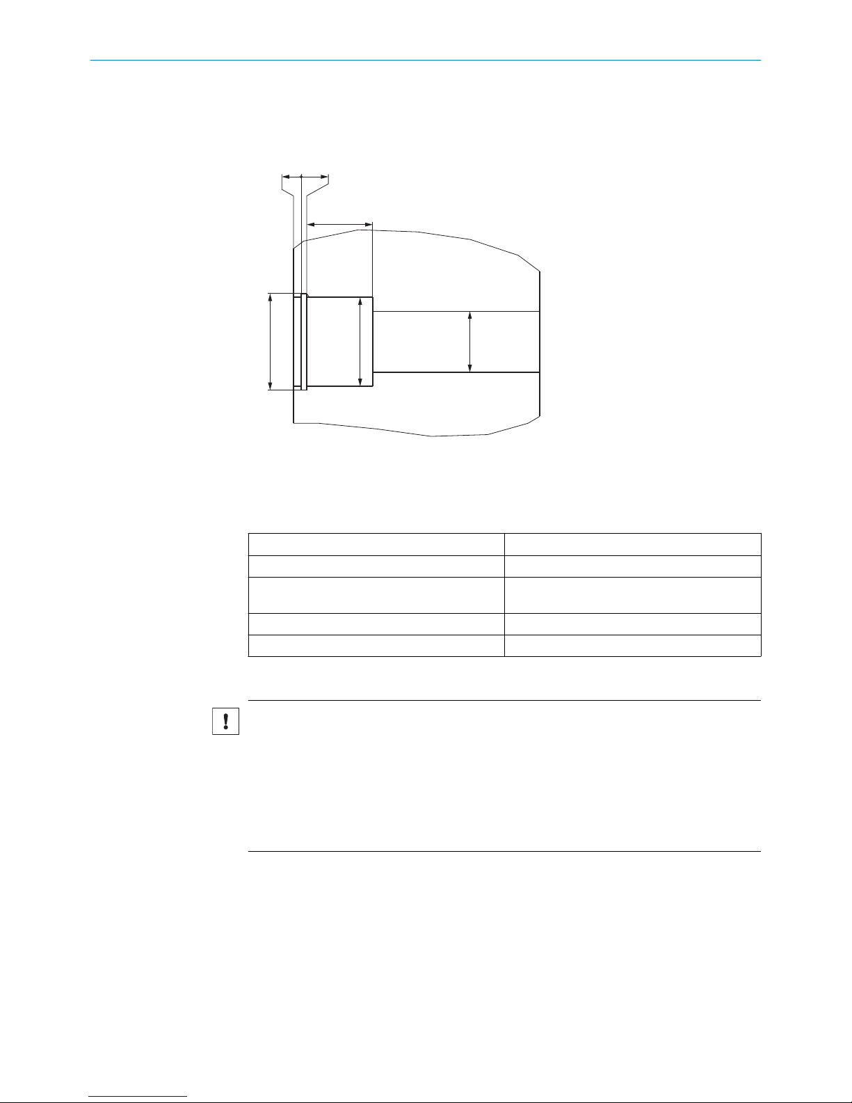
1
Ø 24
(0.94)
Ø 46
(1.81)
Figure 19: Face side – MAX48
1
Mounting surface
1
Ø 14
(0.55)
Ø 22
(0.87)
Figure 20: Face side – MAX30
NOTICE
Risk of damage to the device during installation.
Forces acting on the load-bearing features of the housing can damage the device.
b
Do not apply any load on the pressure pipe or behind the head of the device
when mounting the sensor.
1
222
Figure 21: Areas requiring lubrication
1
Oil inlet
2
Areas requiring lubrication
7. Lubricate the indicated areas via the oil inlet.
4.3.3 Installation with an M12 connector system
The M12 connector system has an enclosure rating of IP69K and is pre-assembled
ready for installation.
NOTE
When selecting the mating connector, ensure that it also has an enclosure rating of
IP69K.
4 MOUNTING
20
O PE R AT I NG IN S TR U CT I ON S | MA X 8022793/ZXZ4/2018-07-24 | SICK
Subject to change without notice
Page 21

Figure 22: M12 connector system
1. Mount and engage the contact carrier in the flange plate.
NOTICE
b
When mounting the contact carrier in the flange, ensure the lug of the con‐
tact carrier is aligned correctly.
2. Press the flange plate into the bore in the cylinder wall.
3. Fasten the flange plate using suitable screws or rivets.
4. Proceed to the next step, see step 5, page 19.
Recommended screws for mounting the M12 flange
The screws should be selected so that no collision with the coupling nuts of the con‐
nected mating connectors can occur, e.g.,:
•
M3 socket head cap screw with flat head
•
DIN 912 hexagon socket head cap screw
•
ISO 14580 Torx screw
•
DIN 84 slotted-head screw
•
Comparable Phillips head screws or self-tapping screws
A soluble screw locking adhesive should be used when installing the screws.
Alternatively, the flange plate can be fastened using DIN 6660 button-head rivets.
4.3.4 Installation with a cable connector and cable gland
Figure 23: Encoder installed in the hydraulic cylinder with cable connector and cable gland
1. Guide the cable through the cable gland.
2. Mount the cable gland in the threaded bore.
3. Secure the tapered seal and coupling nut.
4. Proceed to the next step, see step 5, page 19.
MOUNTING 4
8022793/ZXZ4/2018-07-24 | SICK O PE R AT I NG IN S TR U CT I ON S | MA X
21
Subject to change without notice
Page 22

Recommendations regarding the cable gland
For devices with a cable connection, a protection class rated (preferably IP68) metallic
cable gland should be used for sealing and strain relief. The cable glands should also
be protected against damage by surrounding them with metal profiles (e.g. U-steel). A
suitable cable gland is available as an accessory, see figure 40, page 52.
Recommendations regarding connectors for devices with a cable connector
When installing connector plugs on devices with a cable connector, please consider the
following:
•
Enclosure rating: (preferably IP68)
•
Connector housing:
Metal or impact-resistant plastic (check media resistance)
•
Protect against external influences: enclose the cable sheath and male connector
•
Prevent fluid ingress: the cable sheath should ideally be coated with sealing com‐
pound at offset locations
•
Polarity: ensure correct polarity
•
Male connector with screw terminals:
Apply ferrules and clamp all strands in the ferrule
•
Soldered connections: no projecting strands or “cold joints”
•
Crimp contacts: use a suitable tool to produce a gas tight crimp
•
ESD protection: protect workplaces and persons from electrostatic discharge
•
Prevent fluid ingress:
Use suitable caps to seal the male connector after installation
•
Screwed cable glands: protect by enclosing within steel profiles
4.4 Install the retaining screw
The retaining screw prevents the housing from moving in the axial direction. A DIN 913
M5x10 threaded pin with tapered head should be used for this purpose. Use a soluble
screw locking adhesive when installing the threaded pin.
NOTICE
Risk of damage to the device during installation.
The screw must only rest in the slot and not be tightened too hard.
b
Tighten the screws with a torque of 0.5 Nm ... 1.0 Nm.
4.5 Cylinder handling after encoder installation
4.5.1 Washing and drying the cylinder
To protect the connecting cable and male device connector from ingress of cleaning
agents, please observe the following:
Encoder with M12 connector system
•
Drying temperature: max. 90 °C
•
Pressure of the cleaning fluid: ≤ 5 bar
•
Protective cap: use the supplied plastic protective cap
•
In case of higher pressures: use a metallic protector
•
Protection class: IP69K
4 MOUNTING
22
O PE R AT I NG IN S TR U CT I ON S | MA X 8022793/ZXZ4/2018-07-24 | SICK
Subject to change without notice
Page 23

Preventing ingress of cleaning agents into the electronics when washing cylinders with
an already installed M12 male connector.
To protect cylinders with an installed linear encoder against water ingress during wash‐
ing, a brass cap can be screwed onto the M12 male connector. Contact SICK for the
relevant information.
Encoder with cable connector / installed male device connector
•
Cable connectors/male device connector: protect against ingress of cleaning
agents using suitable sheathing
•
Screwed cable glands: protect against ingress of moisture
4.5.2 Electrostatic painting of the cylinder
The electrostatic painting process uses very high voltages (up to 100 kV) which can
damage the electronics of the encoder integrated into the cylinder. To avoid damage,
observe the following when painting the cylinder:
•
To avoid electrical isolation of the piston rod and the cylinder/sensor housing, do
not the suspend the cylinder by the piston rod
•
Clean off all lacquer and other residues from the hanging devices in the paint
shop, all connectors used to short-circuit the connecting wires, and all connec‐
tions to the paint shop earth
Painting of cylinders with an installed encoder and M12 connector system or male
device connector
To protect the sensor electronics, use metal protective caps that meet the following
requirements:
•
The cap must not be made from aluminum
•
The cap must be made from a permanently electrically-conductive material
•
The cap must have an M12x1 thread
•
The cap must be screwed on until it contacts the flange plate on the connector
as desired
•
Always use a torque of ≥ 5 Nm when tightening the cap
•
Make sure no paint particles get onto the thread or
pin contacts
Any paint particles on the outside of the cap will not impair the sensor.
A suitable cap can be purchased from the manufacturer as an accessory.
Painting of cylinders with an installed encoder and cable connector or third-party con‐
nector
Cylinders with an installed encoder and cable connector cannot be electrostatically
painted because the cable connector is not protected against over voltages. Reliable
electrostatic painting is only possible when using a combination of M12 connector sys‐
tem and protective cap.
4.5.3 Mounting the cylinder on mobile hydraulic machines
When mounting the cylinder on mobile hydraulic machines, ensure no male connectors,
cables or cable ends can be damaged in the process.
4.5.4 Electrical and electrostatic interference
Insulation tests
When performing insulation tests on mobile hydraulic machines, disconnect all encoder
connection cables to avoid damage from high voltages.
MOUNTING 4
8022793/ZXZ4/2018-07-24 | SICK O PE R AT I NG IN S TR U CT I ON S | MA X
23
Subject to change without notice
Page 24

Welding
Welding currents may be produced when carrying out welding work on nearby compo‐
nents. Welding currents can damage the pressure pipe or the electronics.
The following must also be observed when welding:
•
Disconnect all electrical connections during welding
•
Never fasten the grounding point to the piston rod or cylinder pipe
•
Never perform welding work directly on the cylinder
•
Never perform welding work near a cylinder with an encoder installed in it
•
Welding currents and similar effects can also arise at any bearing location on the
machine
4 MOUNTING
24
O PE R AT I NG IN S TR U CT I ON S | MA X 8022793/ZXZ4/2018-07-24 | SICK
Subject to change without notice
Page 25

5 Electrical installation
5.1 Electrical connection
The encoder is equipped with an M12 connector system.
A variant with a cable connection is also available. Male device connectors must be
used in this case.
Enclosure ratings
To guarantee an IP69K enclosure rating (M12 connector system), a suitable mating
connector must be used.
5.1.1 Connection diagram, pin assignment for 4-pin M12 male connector
4
3
1
2
Figure 24: Pin assignment for 4-pin M12 connector
Pin assignment as per position 13 of the type code.
Table 8: Pin assignment for 4-pin M12 connector
Type code A B M
12/24 VDC 1 1 2
GND (0 V) 3 3 3
Signal 4 2 4
n.c. 2 4 1
5.1.2 Cable connection diagram
Connection scheme as per position 13 (= “K”) of the type code.
Table 9: Allocation of wire colors (voltage)
12/24 VDC BR (brown)
GND (0 V) BL (blue)
Voltage signal BK (black)
Table 10: Allocation of wire colors (current)
12/24 VDC BR (brown)
GND (0 V) BL (blue)
Current signal WH (white)
5.1.3 Connection diagram, pin assignment for 5-pin M12 male connector
4
3
1
2
5
Figure 25: Pin assignment for 5-pin M12 connector
Pin assignment as per position 13 of the type code.
ELECTRICAL INSTALLATION 5
8022793/ZXZ4/2018-07-24 | SICK O PE R AT I NG IN S TR U CT I ON S | MA X
25
Subject to change without notice
Page 26

Table 11: Pin assignment for 5-pin M12 connector
Type code C D
12/24 VDC 2 1
GND (0 V) 3 3
CAN_HI 4 4
CAN_LO 5 5
n.c. 1 2
5.1.4 Connection sequence
Connect the wires in the following sequence:
1. Connect the 12/24 VDC voltage supply.
2. Connect the GND (0 V).
3. Connect the signal.
5.2 Connection diagram for vehicle electronics
SIG
GND
+VDC
ECU
BAT
+
–
GEN
M
2
1
Figure 26: Connection diagram
1
Chassis GND
2
Cable shielding (optional)
To guarantee fault-free operation of the device, the cylinder must be connected to
machine ground (Chassis GND).
The physical contact with another machine component equalizes the potential of the
cylinder. If the cylinder is mounted in an insulated manner, a separate grounding must
be provided, e.g., by connecting a ground strap directly to the cylinder.
Cable shielding
The encoder is adequately shielded by the cylinder when installed, and therefore has
not been provided with its own shielding. If a shielded cable is used, it is necessary to
check, depending on the application, whether one side or both sides of the shield
should be connected to machine ground. Any high voltage or high frequency fields in
the vicinity can influence the shielding and the signal in the cable.
5 ELECTRICAL INSTALLATION
26
O PE R AT I NG IN S TR U CT I ON S | MA X 8022793/ZXZ4/2018-07-24 | SICK
Subject to change without notice
Page 27

6 Commissioning
6.1 Putting the encoder into operation
1. Check that the connectors have been connected correctly: see "Connection dia‐
gram, pin assignment for 4-pin M12 male connector", page 25.
2. Select a suitable fuse: see "Select a suitable fuse", page 27.
3. Set up the filter wiring: see "Set up the filter wiring - analog", page 27.
4. Put the device into operation.
5. Check the functioning of the encoder: see "Checking the functioning of the
encoder", page 38.
6.2 Select a suitable fuse
When selecting a suitable fuse, the transient peak current when switching on the
device for the time must be taken into consideration:
Table 12: Inrush current when switching the device on
Inrush current for an supply voltage of 12 VDC 2.5 A / 50 μsec typical
Inrush current for an supply voltage of 24 VDC 5.0 A / 50 μsec typical
6.3 Set up the filter wiring - analog
Thermal noise, for example from resistors, becomes evident when the signal output is
amplified sufficiently. The supply voltage ripple (see "Technical data", page 43) and
other sources of interference, e.g., electromagnetic interference, can also affect the
quality of the analog output signal. To reduce the noise when acquiring analog mea‐
surement data, it is essential to use a filter.
A suitable filter, for example, is a combination of R1 = 50 Ω and C1 = 100 nF to 1 µF.
This will keep the signal delay time within the cycle time (internal measurement fre‐
quency) while not changing the dynamic behavior significantly.
VDC
+
GND GND GND
GND
R1
C1
1µF
ECU
Input
A/D converter
e.g., 12 bit →
4,096 steps
SIG
Figure 27: Filter wiring
NOTICE
The A/D converter at the input of the installed electrical controller will determine the
resolution of the encoder, e.g.,:
•
8 bit = 256 steps
•
10 bit = 1,024 steps
•
12 bit = 4,096 steps
6.4 Power-up and output signal in the event of a fault
When switching on the device, the signal output is ≥ F.S.O = Full Scale Output. After that
the device is ready for use.
COMMISSIONING 6
8022793/ZXZ4/2018-07-24 | SICK O PE R AT I NG IN S TR U CT I ON S | MA X
27
Subject to change without notice
Page 28

Table 13: Operational statuses and output signal
Output signal
F.S.O during power-up in the event of a fault
4.00 ... 20.00 mA
Unusable signal
> 21.0 mA
0.50 ... 4.50 V > 5.1 V
0.25 ... 4.50 V > 5.1 V
0.50 ... 9.50 V > 10.0 V
PWM (duty cycle) ≥ 99%
Digital: CANopen / SAE J1939 Boot message Error message “FFFF”
Fault:
a) Position magnet missing
b) Position magnet in null or cushion zone
c) Malfunction or failure of the magnetostrictive element
During power-up (see "Technical data", page 43), the output signal is defined as an
unusable signal. The machine controller must take this into consideration in its pro‐
cessing. After power-up, the linear encoder is ready for operation. The output signal
behaves as described in the event of a fault.
6.5 Bus termination - digital
VDC
+
GND
ECU
CAN_LO
120 Ω
CAN_HI
Figure 28: Bus termination
Data transmission in the CAN bus is serial (2-wire bus system). The voltage difference
between the CAN_HI and CAN_LO data lines is one bit of information. To prevent signal
reflections, the data lines must be terminated with a 120 Ω terminator on the open bus
end. The terminator must be inserted between CAN_HI and CAN_LO.
6.6 Tolerance considerations for the set point
The set points (zero/end point) of the device are adjusted by the manufacturer to a tol‐
erance of ± 1 mm.
NOTICE
Further tolerances must be observed when installing the cylinder.
During teach-in, the piston rod moves to the zero point and to the end point in order to
eliminate all tolerances in the cylinder/encoder combination. The measured signals are
programmed in the controller accordingly. When operating the device without teach-in,
please note the following tolerance-related information:
Table 14: Tolerances when operating the device without teach-in
Example for a measuring range of 400 mm
Analog VDC Analog mA PWM (duty
cycle)
CANopen
SAE J1939
6 COMMISSIONING
28
O PE R AT I NG IN S TR U CT I ON S | MA X 8022793/ZXZ4/2018-07-24 | SICK
Subject to change without notice
Page 29

Example for a measuring range of 400 mm
Signal 0.5 ... 4.5 V 4 ... 20 mA 10 … 90% PDO
Range 4000 mV 16 mA 80% 4,000 digits
Zero/end point ± 1.0 mm ± 10 mV ± 0.04 mA ± 0.2% ± 10 digits
Position magnet ± 1.0 mm ± 10 mV ± 0.04 mA ± 0.2% ± 10 digits
Mechanical assembly ± 0.5 mm ± 5 mV ± 0.02 mA ± 0.1% ± 5 digits
Total of all tolerances ± 2.5 mm ± 25 mV ± 0.10 mA ± 0.5% ± 25 digits
Table 15: Zero end point
Example for a measuring range of 400 mm
Output Analog VDC Analog mA PWM (duty
cycle)
CANopen
SAE J1939
Signal 0.5 ... 4.50 V 4 ... 20 mA 10 … 90% PDO value
Zero point ± 25 mV ± 0.10 mA ± 0.5% ± 25 digits
min. zero point 0.475 V 3.90 mA 9.5% 275 digits
max. zero point 0.525 V 4.10 mA 10.5% 325 digits
End point (F.S.) ± 25 mV ± 0.10 mA ± 0.5% ± 25 digits
min. end point 4.475 V 19.90 mA 89.5% 3,975 digits
max. end point 4.525 V 20.10 mA 90.5% 4,025 digits
After installation of the encoder in the cylinder, deviations from the target values will
arise due to these permissible tolerances. These deviations must be taken into consid‐
eration when setting limit values in the controller:
Table 16: Deviation from the limit values
Typical values
Cylinder stroke (mm)
200 mm 400 mm 800 mm
Output signal Tolerances
Analog VDC ± 25 mV ± 25 mV ± 15 mV
Analog mA ± 0.20 mA ± 0.10 mA ± 0.05 mA
PWM (10 … 90% duty cycle) ± 1.0% ± 0.5% ± 0.25%
CANopen / SAE J1939 ± 25 digits ± 25 digits ± 25 digits
6.7 CAN bus protocols
CAN bus is a machine level, open field bus for serial data transmission between a cen‐
tral controller (master) and decentralized field devices (slaves). Various protocols can
be used for the data transmission depending on the application. The device can be
ordered with either CANopen or SAE J1939 protocol support. Each protocol is config‐
ured differently, which affects how the device is integrated into the network, and the
operating characteristics of the device.
CANopen
The CANopen version of the device is suitable for operation as a slave in CAN bus net‐
works using the CiA Standard DS 301 V3.0 data protocol. This protocol corresponds to
the DS 406 V3.1 encoder profile. The device is connected directly to the bus as a node
of the bus system. The device distinguishes between four different operating modes ini‐
tiated by the controller. These modes are defined in the CANopen standard:
COMMISSIONING 6
8022793/ZXZ4/2018-07-24 | SICK O PE R AT I NG IN S TR U CT I ON S | MA X
29
Subject to change without notice
Page 30

•
Initialization: The device performs a hardware initialization and loads the most
recently saved standard configuration.
•
Pre-operational: The device can be configured via the CAN bus.
•
Operational: The device sends its measurement data via the CAN bus.
•
Stopped: The device stops transmitting data and waits for further commands.
SAE J1939
SAE J1939 is a multi-master protocol developed especially for applications in the
mobile field, i.e. for commercial and conveyor vehicles, as well as for construction, agri‐
cultural and forestry machines. An SAE J1939 network consists of various ECUs (Elec‐
tronic Control Units). An ECU can address messages to multiple CAs (Controller Applica‐
tions). After commissioning, the bus subscribers are automatically assigned addresses.
The CAN bus subscribers are now fully operable.
6.8 Communication objects
6.8.1 CANopen
When the device is in operational mode, the evaluation electronics integrated into the
device convert the measurement data into CAN messages, and transmit these mes‐
sages on the CAN bus. Where they can be received and processed by the controller. The
CAN bus uses the following communication objects for data transmission:
•
SDO (Service Data Object):
SDOs are used to set or query parameters relating to the encoder configuration.
These are accessed from the internal object directory of the device. To process
SDOs, the device must be in either the pre-operational or operational mode.
•
PDO (Process Data Object):
PDOs transmit process data, such as position and speed, to the controller. PDOs
are only generated in operational mode.
•
NMT (Network Management):
NMTs control the status of the network and individual components. They can also
be used for monitoring purposes using the following objects:
°
SYNC object:
The SYNC object synchronizes the bus communication, i.e. synchronous PDOs
are sent to the controller after a SYNC object is received.
°
Emergency object:
The emergency object sends error messages. As they generally have a higher
priority than PDOs, these emergency objects will be transmitted first.
°
Nodeguard object:
The CANopen linear encoder uses the node guarding protocol to perform the
error control services of the CANopen network.
The bus master uses a remote frame to send a nodeguard message to the
CANopen slave, and in response the slave reports its current NMT status
using a standard nodeguard message. The nodeguard frame format, and the
NMT state value definitions are shown in the following tables. The nodeguard
protocol is activated as default.
According to the CANopen protocol, each message has the following structure:
Table 17: Message in CANopen
SOF Arbitration Control Data Field CRC ACK EOF Interframe Space
1 11 1 6 0..8 bytes 15 1 1 1 7 ≥ 3
6 COMMISSIONING
30
O PE R AT I NG IN S TR U CT I ON S | MA X 8022793/ZXZ4/2018-07-24 | SICK
Subject to change without notice
Page 31

6.8.2 SAE J1939
SAE J1939 features an extended message arbitration and a 29-bit extended message
identifier. This extension features a different message prioritization and assignment of
bus subscribers. For large quantities of data, it is possible to utilize a separate trans‐
port protocol. The communication objects for SAE J1939 are:
•
PDU (Protocol Data Unit):
There are two types of PDUs. PDU1 is used for peer-to-peer data transmission,
PDU2 is addressed to all bus subscribers.
•
PG (Parameter Groups):
PG refers to the grouping of process data and parameters for transmission in a
message. This parameter group data structure ensures efficient bus loading.
•
PGN (Parameter Group Number):
The PGN is a unique and standardized identifier of the parameter group.
•
SPN (Suspect Parameter Number):
The SPN uniquely identifies a parameter signal and is prescribed by the protocol.
This ensures that every SAE J1939 compatible device knows the parameter struc‐
ture.
•
TP (Transport Protocol):
TP is used for separate data transmission above 8 bytes.
According to the SAE J1939 protocol, each message has the following structure:
Table 18: CAN bus data protocol with J1939 identifier
PDU
SOF Arbitration Identifier Control Data
Field
CRC ACK EOF
1 Priority 3 2 PDU
Format 8
PDU
Specific 8
Source 8 6 0..8 bytes15 1 1 1 7
6.9 Configuration and system startup
After electrical connection to the network, the device is ready for commissioning and
configuration. Before actual system startup, the communication parameters for opera‐
tion need to be set in the CAN bus. Only the basic procedure is described in these oper‐
ating instructions. Please refer to the accompanying programming instructions for
details of all the available commands for configuring the device.
6.9.1 Configuring CANopen
Setting the node parameters
To be able to operate the device in a CAN bus network, it is necessary to first configure
the network characteristics. The basic settings for integrating a bus subscriber are
made using LSS (Layer Setting Services). Every device (node) in the CAN network is
uniquely identified by its LSS address. This address is composed as follows:
Table 19: LSS address
CANopen
Vendor-ID 0x1000056
Product code as per product key
Revision number as per product key
Serial Number actual serial number of the CANopen encoder
COMMISSIONING 6
8022793/ZXZ4/2018-07-24 | SICK O PE R AT I NG IN S TR U CT I ON S | MA X
31
Subject to change without notice
Page 32

Parameters specific to the CAN bus, such as baud rate and node ID, are also configured
and saved via the LSS service. Both the baud rate and node ID of the encoder must be
configured for operation in the specific CAN bus implementation.
Setting the node ID
NOTE
When programming the node ID, only one device or node must be connected.
Every device or node must be assigned a number (node ID). This number is used to
identify the node within the CANopen network. Each node ID must be unique. The
CANopen node ID must be in the range of 1 - 127, and can be preset when ordering. To
ensure error-free operation of the network, the ID of every node in the CAN bus must be
unique.
The node ID of the device can be set using the following command sequence:
Table 20: Setting the node ID
Data source COB-ID Data Destination
Controller 0x7e5 04; 01; 00; 00; 00; 00; 00; 00 Sensor
Controller 0x7e5 11; 7d*; 00; 00; 00; 00; 00; 00 Sensor
Sensor 0x7e4 11; 00; 00; 00; 00; 00; 00; 00 Controller
*
Node address values can be between 1 and 127 (for example 125).
A change in node address is effective immediately.
To permanently save the node address, the following command must be sent:
Table 21: Saving the node ID
Data source COB-ID Data Destination
Controller 0x7e5 17 Sensor
Sensor 0x7e4 17; 00; 00; 00; 00; 00; 00; 00 Controller
Setting the baud rate
The baud rate indicates the speed of operation of the device and also the entire CAN
bus. The device and entire network must be set to the same baud rate.
The maximum baud rate is limited by the cable length used for the CAN network as a
whole. The device is delivered with a preset, order-dependent baud rate. If this baud
rate needs to be changed, it can be configured via the LSS.
Table 22: Baud rate as a function of cable length
Cable length Baud rate (kBit/s) Table index
< 25 m 1000 00
< 50 m 800 01
< 100 m 500 02
< 250 m 250 03
< 500 m 125 04
< 1000 m 50 06
< 2500 m 20 07
< 5000 m 10 08
The baud rate can be set using the following commands:
6 COMMISSIONING
32
O PE R AT I NG IN S TR U CT I ON S | MA X 8022793/ZXZ4/2018-07-24 | SICK
Subject to change without notice
Page 33

Table 23: Setting the baud rate
Data source COB-ID Data Destination
Controller 0x7e5 04; 01; 00; 00; 00; 00; 00; 00 Sensor
Controller 0x7e5 13; 00; 02*; 00; 00; 00; 00; 00 Sensor
Sensor 0x7e4 13; 00; 00; 00; 00; 00; 00; 00 Controller
*
Table index
The baud rate becomes active after saving the changes, and the next time the encoder
is switched on. To save the baud rate, the following command must be sent:
Table 24: Saving the baud rate
Data source COB-ID Data Destination
Controller 0x7e5 17; 00; 00; 00; 00; 00; 00; 00 Sensor
Sensor 0x7e4 17; 00; 00; 00; 00; 00; 00; 00 Controller
6.9.2 Configuring SAE J1939
In the SAE J1939 specification, the maximum length of the network is limited to
40 meters, and the baud rate is fixed at 250 kBit/sec. It is therefore not necessary to
configure these parameters when integrating the device. Furthermore, the number of
nodes is limited to 30 ECUs (Electronic Control Units). Each ECU can, however, control
multiple CAs (Controller Applications). Up to 253 CAs in total can be implemented in the
network.
NMT (Network Management)
SAE J1939 supports extended network management. This requires subscribers to first
register themselves in the network with a unique address prior to system startup
(address claiming). Normal bus operation is only started after all subscribers have suc‐
cessfully logged in. Correct address assignment is checked continuously during opera‐
tion. A new source address can be assigned during operation. In addition to the source
address, every bus subscriber is provided with a unique name to identify it within the
network and to prioritize the allocation of addresses. The naming conventions are
defined in SAE J1939 and are structured as follows:
Table 25: Naming structure for subscribers according to J1939
Byte 0 Byte 1 Byte 2 Byte 3 Byte 4 Byte 5
Identify
Number
Manufacturer Code ECU Instance Function
Table 26: Naming structure for subscribers according to J1939
Byte 6 Byte 7
Reserved Vehicle System Vehicle System
Instance
Industry Group Arbitrary Address
Capable
Table 27: Setting the source address
Data source COB-ID Data Destination
Controller 0x10ff54d4 01; nSA*; 23; 01; 20; 07; 00; 00 Transducer
Transducer No response Controller
*
nSA: new source address
COMMISSIONING 6
8022793/ZXZ4/2018-07-24 | SICK O PE R AT I NG IN S TR U CT I ON S | MA X
33
Subject to change without notice
Page 34

6.9.3 System startup for CANopen
After configuring the node parameters, the device can be integrated into the network.
When switched on or reset, the encoder performs a hardware initialization to bring all
components into a defined initial state. Next the device- and communication-specific
parameters are loaded from an EEPROM and the configuration adopted.
Once the initialization has been completed, the device reports its node ID and pre-opera‐
tional mode to the network master by means of a boot-up message. While in this mode,
the device can be configured via service data objects (SDOs).
The SDO identifiers are generated automatically based on the node ID. The communi‐
cation via SDOs to configure the device takes the form of a peer-to-peer connection
between the network master and the device. The identifiers for the other objects are
also allocated according to the CANopen standard. They can, however, be changed at
any time in the CANopen network via a DBT master. If necessary, the changed parame‐
ters can be saved in the EEPROM and loaded automatically the next time the device is
switched on and configured.
Once the configuration process is finished, the encoder is switched from pre-operational
to operational mode using a Start_Remote_Node command. While in this mode, user
data can be transmitted (via PDOs). The transmission of the PDOs can occur in one of
two ways:
Either the encoder sends its data cyclically, or data transmission is triggered by the
receipt of a SYNC object.
To initiate the sending of position messages by the encoder, it is necessary to first send
a node start message:
Table 28: Node start message
Data source COB-ID Data Destination
Controller 0x000 01; 00*; 00; 00; 00; 00; 00; 00 Sensor
*
00: Starts all CAN nodes
To stop the sending of position data, it is necessary to send a pre-operational message:
Table 29: Pre-operational message
Data source COB-ID Data Destination
Controller 0x000 80; 00*; 00; 00; 00; 00; 00; 00 Sensor
*
00: Sets all nodes to pre-operational mode
6.9.4 System startup for SAE J1939
After the device is connected to the network and switched on, it attempts to register
itself with the network master using a source address. This address claiming is per‐
formed automatically by the network. After assignment of a unique network address,
the device starts sending position data and is also ready to receive configuration data.
6.9.5 Setting CANopen operating parameters
At system startup (power on, reset), the device loads the operating parameters stored
in the EEPROM. These are either the factor-set values, or previously changed and saved
values.
Changes are made, for example, via SDOs while in pre-operational mode. The identifiers
are automatically set to suitable default values and saved when programming the node
ID. They can subsequently be changed.
6 COMMISSIONING
34
O PE R AT I NG IN S TR U CT I ON S | MA X 8022793/ZXZ4/2018-07-24 | SICK
Subject to change without notice
Page 35

These operating parameters are stored in the object directory of the device, which pro‐
vides the means for implementing the internal characteristics and functions of the
device, as well as external communication. For this purpose, the object directory is
divided into two parts: a Communication Profile, and a Device Profile.
•
Communication Profile:
The Communication Profile contains the parameters relevant to communication,
e.g., identifier settings and PDO configuration settings. The device is equipped
with the encoder communication protocol (Device Profile for Encoder – DS406
Vers. 3.1). This enables devices from different manufacturers to be easily linked to
one another and replaced.
•
PDO transmission type:
By default, the PDO transmission type is set to asynchronous, i.e. the encoder
transmits its process data independently according to the configured cycle time.
The PDO transmission type can also be set in such a way that process data is only
sent after a SYNC message is received.
•
PDO object mapping:
The device does not support dynamic mapping or changing of the mapping para‐
meters. PDO1 transmits the position and speed.
•
Error messages:
The device automatically sends an emergency object when an error arises.
•
Device profile:
The parameters important to the operation of the encoder, such as position reso‐
lution, speed resolution, and cycle time, are stored in the Device Profile. Two
important operating parameters are:
°
Resolution:
The factory-default resolution of the device is 100 μm. The resolution for
motion speed is set to 1 mm/s by default. For more information, see the pro‐
gramming instructions.
°
Cycle time:
This setting is the cycle time for transmission of PDOs. The value can be in
the range of 1 ... 65535 ms. Programming the cycle time (object 6200) only
affects the PDO1 event timer (see DS406 V3.0).
The cycle time setting must match the setting configured for the CAN bus net‐
work. If the cycle time is too short, and the baud rate is low and there are
many subscribers, the bus can become overloaded due to the increased vol‐
ume of data.
The cycle time can be set using the following commands (e.g., 10, node ID =
127*):
Table 30: Setting the cycle time
Data source COB-ID Data Destination
Controller 0x67f* 22; 00; 62; 00; 0A; 00; 00; 00 Sensor
Sensor 0x5ff* 60; 00; 62; 00; 00; 00; 00; 00 Controller
To permanently save the cycle time, the Save parameters command must be executed:
Table 31: Saving the cycle time
Data source
COB-ID Data Destination
Controller 0x67f* 22; 10; 10; 01; 73; 61; 76; 65 Sensor
Sensor 0x7ff* 60; 10; 10; 01; 00; 00; 00; 00 Controller
NOTE
The encoder may take up to 600 ms to respond.
COMMISSIONING 6
8022793/ZXZ4/2018-07-24 | SICK O PE R AT I NG IN S TR U CT I ON S | MA X
35
Subject to change without notice
Page 36

6.9.6 Setting SAE J1939 operating parameters
The operating parameters of the SAE J1939 device variant can be set analogously to
the CANopen variant. The device can receive configuration messages during operation,
and will adopt the settings immediately after receiving the message.
The cycle time can be set using the following commands (e.g., 100*):
Table 32: Setting the cycle time
Data source COB-ID Data Destination
Controller 0x18B2SAMA 4D; 54; 53; 00; 64*; 00*; 00; 00 Sensor
SA
MAX CAN J1939 standard sensor source address
MA
Master source address
*
e.g., 64; 00: Bytes to configure transmission repetition rates
6.9.7 CANopen encoder data during operation
Data is outputted by means of a Process Data Object (PDO). The PDO contains the posi‐
tion and speed data.
Data format
The resolution of the position data is fixed at 100 μm, and the resolution of the speed
data is 1 mm/s. The currently set values can be read under index 6005 of the object
directory. All position data are stored as 32-bit integer values, and speed data as 16-bit
integer values.
Table 33: PDO allocation when using the default settings
Identifier DLC D0 D1 D2 D3 D4 D5
180h + nodeID6 Position magnet 1 Speed magnet 1
The position and speed are calculated as follows:
Position [μm] = position value [counts] * 100μm
Speed [mm/s] = speed value [counts] * 1 mm/s
6.9.8 SAE J1939 encoder data during operation
Data is outputted by means of a Data Record Message.
Table 34: Data Record Message
Identifier DLC D0 D1 D2 D3 D4 D5 D6 D7
0 x 18
PFPSSA
8 Position Speed Status Error Code Limit Sta‐
tus
0xFF
PF
PDU format is fixed to 255 (0xFF)
PS
PDU Specific can be 0-255 (0x00 - 0xFF)
SA
MAX CAN J1939 standard sensor source address
6.9.9 CANopen error messages
An emergency object is sent whenever there is a change to the internal error status reg‐
ister (even if the error has since been rectified). The object comprises 8 data bytes and
is structured as follows:
Table 35: Emergency object
Identifier DLC D0 D1 D2 D3 D4 D5 D6 D7
0x80 + nodeID8 Error Code Error register Manufacturer-specific
The following errors are reported in the emergency object:
6 COMMISSIONING
36
O PE R AT I NG IN S TR U CT I ON S | MA X 8022793/ZXZ4/2018-07-24 | SICK
Subject to change without notice
Page 37

Table 36: Error codes
Error code Relevance
0x0000 Device is operating without errors
0x5000 Device hardware error
0X6300 Data set error
6.9.10 SAE J1939 error messages
SAE J1939 does not provide separate error objects. The device status is reported with
every PDU that is sent.
COMMISSIONING 6
8022793/ZXZ4/2018-07-24 | SICK O PE R AT I NG IN S TR U CT I ON S | MA X
37
Subject to change without notice
Page 38

7 Maintenance
7.1 Error table
Table 37: Errors during installation
Error cause Possible consequences
Incorrect pin assignment No signals
Ambient temperature too high Damage to the device components
Cylinder bore hole too small Damage to the device components when
installing the device
Not noticing pointy or sharp edges Damage to male connectors, wires, cables
Careless handling of the device Damage to the device components
Welding work after installation Damage to the sensor housing or
electronics due to welding currents
Damage to the cable Short-circuiting or failure of the electronics
Male connector not sealed Short-circuiting or corrosion of
electronic components due to liquids
Ground or shielding connected incorrectly Signal interference, possible damage to the
electronics
Table 38: Errors during commissioning/operation
Output signal
F.S.O Output signal in the event of a fault
4.00 ... 20.00 mA > 21.0 mA
0.50 ... 4.50 V > 5.1 V
0.25 ... 4.50 V > 5.1 V
0.50 ... 9.50 V > 10.0 V
PWM (duty cycle) > 99%
Digital: CANopen / SAE J1939 Error message “FFFF”
Fault:
a) Position magnet missing
b) Position magnet in null or cushion zone
c) Malfunction or failure of the magnetostrictive element
7.2 Checking the functioning of the encoder
Encoder with analog interface
To verify the proper operation of the device, perform the following checks:
•
Connections and pin assignments
•
Supply voltage
•
Check the device by disconnecting it and testing it using an external supply
•
Check the device using a multimeter as described below
Measure the VDC output signal
Measure the following output signals:
•
0.25 ... 4.75 VDC
•
0.5 ... 4.5 VDC
•
0.5 ... 9.5 VDC
7 MAINTENANCE
38
O PE R AT I NG IN S TR U CT I ON S | MA X 8022793/ZXZ4/2018-07-24 | SICK
Subject to change without notice
Page 39

+
_
VDC
Figure 29: Measuring the output signal in VDC
1. Switch the measuring range of the multimeter to VDC.
2. Connect the multimeter to the signal lead and 0 V lead.
3. Connect the voltage supply (+12/24 V).
4. Connect 0 V (-0 V).
Measuring the 4 ... 20 mA output signal
+
_
mA
Figure 30: Measuring the output signal in mA
1. Switch the measuring range of the multimeter to mA.
2. Connect the multimeter to the signal lead and 0 V lead.
3. Connect the voltage supply (+12/24 V).
4. Connect 0 V (-0 V).
Alternative measuring method: using a resistor (e. g., 100 W):
+
_
VDC
R
Figure 31: Measuring the output signal using a resistor
1. Connect the resistor to the signal lead and 0 V lead.
2. Switch the measuring range of the multimeter to VDC.
3. Connect the multimeter in parallel to the resistor.
When using a resistor of, for example, 100 W, the following values are displayed:
Table 39: Example measurement values
Supply at 4 mA (null zone) at 20 mA (end position)
12 V, 24 V 0.4 V 2 V
7.3 Repairs
All repair work on the device must be carried out by SICK Service.
MAINTENANCE 7
8022793/ZXZ4/2018-07-24 | SICK O PE R AT I NG IN S TR U CT I ON S | MA X
39
Subject to change without notice
Page 40

7.4 Testing and programming
A test device is available for checking the device functionality.
To minimize error sources during functional testing, the test device must be connected
directly to the encoder. A PC can be used to test the functioning of the device, and to
configure the basic settings.
7 MAINTENANCE
40
O PE R AT I NG IN S TR U CT I ON S | MA X 8022793/ZXZ4/2018-07-24 | SICK
Subject to change without notice
Page 41

8 Transport and storage
8.1 Transport and storage conditions
When transporting the fully assembled cylinders, ensure the cable and male connector
of the electrical connection are not subjected to tensile loads.
Store the cylinders in a dry place. When storing the cylinders on top of one another,
ensure no male connectors or cables are crushed.
Cover the connectors and any free cable ends with an anti-static bag. The original pack‐
aging, for example, is suitable for this purpose. Also reuse the dust protection caps of
the connector system when storing the device.
For the part numbers of the original packaging and the dust protection caps, see: see
"Accessories", page 51.
TRANSPORT AND STORAGE 8
8022793/ZXZ4/2018-07-24 | SICK O PE R AT I NG IN S TR U CT I ON S | MA X
41
Subject to change without notice
Page 42

9 Decommissioning
9.1 Dismantling
When dismantling the cylinder and when removing the encoder, ensure no male con‐
nectors, cables or cable ends can be damaged in the process.
9.2 Disposal
Any device which can no longer be used must be disposed of in an environmentally
friendly manner in accordance with the applicable country-specific waste disposal regu‐
lations. As the device is categorized as electronic waste, it must never be disposed of
with household waste.
9 DECOMMISSIONING
42
O PE R AT I NG IN S TR U CT I ON S | MA X 8022793/ZXZ4/2018-07-24 | SICK
Subject to change without notice
Page 43

10 Technical data
10.1 MAX Analog/PWM
Table 40: Technical data – MAX48 Analog / PWM
Performance
Measurand Position
Measuring range MAX48: 0050 … 2,500 mm (in 1 mm steps)
MAX30: 0050 ... 1,500 mm (in 1 mm steps)
Unusable measuring range:
Null zone (zero point) MAX48: 30.0 mm
MAX30: 19.5 mm
Damping (end point) 30.0 mm/ 36.0 mm/ 63.0 mm (depending on type)
Power-up delay < 250 ms
Measuring frequency (internal) 2 ms
Setpoint tolerance
Zero and end point of the usable piston stroke
≤ 1.0 mm
Resolution 0.1 mm typical (noise-free)
Hysteresis ± 0.1 mm
Linearity:
Measuring ranges 50 ... 500 mm F.S. typically ± 0.25 mm
Measuring ranges 501 ... 2,500 mm F.S. typically ± 0.04%
Temperature drift (warm-up phase) max. ± 0.25 mm
Analog interface
Electrical interface Analog
Voltage signal 0.25 … 4.75 VDC
0.50 … 4.50 VDC
0.50 … 9.50 VDC
1.00 … 9.00 VDC
Current signal 4 … 20 mA
PWM interface
Pulse width 05 … 95%
10 … 90%
15 … 85%
20 … 80%
25 … 75%
Pulse rate 250 Hz
300 Hz
400 Hz
500 Hz
Electrical connection
M12 male connector 4-pin, wire length
060 … 240 mm (depending on type)
3-wire cable 3 x 0.32 mm² (AWG22),
stripped 300 … 10,000 mm (depending on type)
Electrical data
Supply voltage 12 VDC (8 ... 16 VDC)
24 VDC (8 ... 30 VDC)
TECHNICAL DATA 10
8022793/ZXZ4/2018-07-24 | SICK O PE R AT I NG IN S TR U CT I ON S | MA X
43
Subject to change without notice
Page 44

Electrical data
Supply voltage ripple < 1% p-p
Power consumption:
12 VDC voltage signal ≤ 0.5 W
24 VDC voltage signal ≤ 0.5 W
24 VDC current signal / PWM ≤ 1.0 W
Current consumption:
12 VDC voltage signal ≤ 30 mA
24 VDC voltage signal ≤ 20 mA
24 VDC current signal / PWM ≤ 40 mA
Load resistance:
Voltage signal RL ≥ 10 kΩ
Current signal 100 Ω < RL < 500 Ω
Switch-on current:
12 VDC supply voltage 2.5 A / 50 µsec typical
24 VDC supply voltage 5.0 A / 50 μsec typical
Over voltage protection ISO 16750-2: ≤ + 36 VDC on all poles
Reverse polarity protection ISO 16750-2: on all poles
Insulation resistance ISO 16750-2: Riso ≥ 10 MΩ, 60 sec
Dielectric strength ISO 16750-2: 500 VDC (0 VDC to housing)
Dimensions
Size MAX48: 48f7 mm (for installation in a 48H8 clearance)
MAX30: 31f7 mm (for installation in a 31H8 clearance)
Unusable range:
Null zone (zero point) MAX48: 30.0 mm
MAX30: 19.5 mm
Damping (end point) 30.0 mm/ 36.0 mm/ 63.0 mm (depending on type)
Pressure pipe Ø 7 mm or 10 mm (depending on type)
O-ring MAX48: Ø 40.87 x 3.53 mm
MAX30: Ø 24.99 x 3.53 mm
Support ring MAX48: Ø 42.6 x 48 x 1.4 mm
MAX30: Ø 31 x 25.8 x 1.4 mm
M12 flange EN 61076-2-101 DM 20 x 20 mm - 14 mm hole pattern
3-wire cable Ø 5.2 mm, 3 x 0.32 mm² (AWG22),
stripped 300 … 10,000 mm (depending on type)
Material
Pressure pipe Stainless steel 1.4306, AISI 304L
Electronics housing Stainless steel 1.4305, AISI 303
O-ring NBR 70
Support ring PTFE
M12 male connector insert Glass fiber reinforced polyamide, nickel-/gold-plated brass contacts
M12 flange Stainless steel with O-ring (NBR70)
Cable PUR cable sheath / PVC strand
10 TECHNICAL DATA
44
O PE R AT I NG IN S TR U CT I ON S | MA X 8022793/ZXZ4/2018-07-24 | SICK
Subject to change without notice
Page 45

Ambient data
EMC EU Directive 2014/30/EU CE marking
EU Directive 2009/64/EU Agricultural machinery
Generic standards
Immunity as per EN 61000-6-2 EN 61000-4-3 High-frequency electromagnetic fields
EN 61000-4-4 Conducted fast transients (burst)
EN 61000-4-5 Conducted emission voltage (surge) Class2
EN 61000-4-6 Conducted high-frequency signals
EN 61000-4-8 Magnet fields
Radiated emissions as per EN 61000-6-3 CISPR25 High-frequency radiated interference
Immunity to interference
Agricultural and forestry machines (ISO 14982)
Construction machines EN 13309 / ISO13766
ISO 11452-2 High-frequency electromagnetic fields
ISO 11452-4 Bulk Current Injection
ISO 11452-5 Strip Line Method
Emitted interference
Agricultural and forestry machines (ISO 14982)
Construction machines EN 13309 / ISO13766
CISPR25 High-frequency radiated interference
Transient pulses ISO 7637-2 test pulse 1/ 2a/2b /3a/3b /4 /5a/5b
ESD (air and contact discharge) EN 61000-4-2
ISO/TR 10605
Enclosure rating
Housing without electrical connection ISO 16750-4: EN 60529
IP67 30 min - 1 m
Housing with cable connector ISO 16750-4: EN 60529
IP67 30 min - 1 m
M12 male connector ISO 16750-4: ISO 20653
IP69K with coupling on;
Spraying: 30 sec. / 100 bar / 80 °C
Temperature ranges
Operating temperature (operating condition)
Allowing for fluid temperature and intrinsic heat‐
ing of the electronics
-40 °C … +105 °C
Ambient temperature (fluid) -30 °C … +95 °C
Permissible relative humidity EN60068-2-30: 90% r.H. (Condensation not permitted)
Storage -20 °C … +85 °C (r.H. 55%)
Resistance to shocks
Drop test ISO 16750-3: IEC 60068-2-31
Single shock ISO 16750-3: IEC 60068-2-27: 100 g, 11 ms
Continuous shocks, 1,000 shocks per spatial
axis
ISO 16750-3: IEC 60068-2-27: 50 g, 11 ms
Resistance to vibrations
Pressure pipe, Ø 10 mm Pressure pipe, Ø 7 mm
Sine
ISO 16750-3: IEC 60068-2-6
10 ... 55 Hz (3.5 mm pp)
55 ... 2,000 Hz 20 g
(24 h/axis)
55 ... 2,000 Hz 15 g
(24 h/axis)
Sine-on-random
ISO 16750-3: IEC 60068-2-80
100 ... 440 Hz 11.3 g (r.m.s.)
10 ... 2,000 Hz 18.1 g (r.m.s.)
(36 h/axis)
10 ... 2,000 Hz 13 g (r.m.s.)
(36 h/axis)
Random
ISO 16750-3: IEC 60068-2-64
10 Hz … 2,000 Hz 20 g (r.m.s.)
(48 h/axis) resonance peaks removed
10 Hz … 2,000 Hz 15 g (r.m.s.)
(48 h/axis) resonance peaks removed
TECHNICAL DATA 10
8022793/ZXZ4/2018-07-24 | SICK O PE R AT I NG IN S TR U CT I ON S | MA X
45
Subject to change without notice
Page 46

Hydraulic pressure
Pressure pipe, Ø 10 mm Pressure pipe, Ø 7 mm
Operating pressure P
N
400 bar 320 bar
Max. overload pressure during operation
(PNx1.2)
480 bar 380 bar
Max. test pressure in cylinder (PNx1.5) 600 bar 480 bar
10.2 MAX Digital CANopen / SAE J1939
Table 41: Technical data – MAX48 Digital CANopen / SAE J1939
Performance
Measurand Position and speed
Measuring range MAX48: 0050 ... 2,500 mm (in 1 mm steps)
MAX30: 0050 ... 1,500 mm (in 1 mm steps)
Speed: 0 … 1,000 mm/sec
Unusable measuring range:
Null zone (zero point) MAX48: 30.0 mm
MAX30: 19.5 mm
Damping (end point) 30.0 mm/ 36.0 mm/ 63.0 mm (depending on type)
Power-up delay < 250 msec
Measuring frequency (internal) Cycle time: CANopen 1 ms
SAE J1939 20 ms
Setpoint tolerance
Zero and end point of the usable piston stroke
≤ 1.0 mm
Solution 0.1 mm typical (noise-free)
Hysteresis ± 0.1 mm
Linearity:
Measuring ranges 50 ... 500 mm F.S. typically ± 0.25
Measuring ranges 501 ... 2,500 mm F.S. typically ± 0.04%
Temperature drift (warm-up phase) max. ± 0.25 mm
Digital interface
Electrical interface Digital
Bus protocols CANopen as per CiA DS-301 V4.1 and SAE J1939
Device profile DS-406 V3.1
Electrical connection
M12 male connector 5-pin, wire length
060 … 240 mm (depending on type)
Electrical data
Supply voltage 24 VDC (8 ... 30 VDC)
Supply voltage ripple < 1% p-p
Power consumption ≤ 1.0 W (24 VDC)
Current consumption ≤ 40 mA (24 VDC)
Bus termination 120 Ω
Switch-on current: typically 5.0 A / 50 µsec (24 VDC supply voltage)
Over voltage protection ISO 16750-2: ≤ +36 VDC on all poles
Reverse polarity protection ISO 16750-2: on all poles
10 TECHNICAL DATA
46
O PE R AT I NG IN S TR U CT I ON S | MA X 8022793/ZXZ4/2018-07-24 | SICK
Subject to change without notice
Page 47

Electrical data
Insulation resistance ISO 16750-2: Riso ≥ 10 MΩ, 60 sec
Dielectric strength ISO 16750-2: 500 VDC (0 VDC to housing)
Dimensions
Size MAX48: 48f7 mm (for installation in a 48H8 clearance)
MAX30: 31f7 mm (for installation in a 31H8 clearance)
Unusable range:
Null zone (zero point) MAX48: 30.0 mm
MAX30: 19.5 mm
Damping (end point) 30.0 mm/ 36.0 mm/ 63.0 mm (depending on type)
Pressure pipe Ø 7 mm or 10 mm (depending on type)
O-ring MAX48: Ø 40.87 x 3.53 mm
MAX30: Ø 24.99 x 3.53 mm
Support ring MAX48: Ø 42.6 x 48 x 1.4 mm
MAX30: Ø 31 x 25.8 x 1.4 mm
M12 flange EN 61076-2-101 DM 20 x 20 mm - 14 mm hole pattern
Material
Pressure pipe Stainless steel 1.4306, AISI 304L
Electronics housing Stainless steel 1.4305, AISI 303
O-ring NBR 70
Support ring PTFE
M12 male connector insert Glass fiber reinforced polyamide, nickel-/gold-plated brass contacts
M12 flange Stainless steel with O-ring (NBR70)
Cable PUR cable sheath / PVC strand
Ambient data
EMC EU Directive 2014/30/EU CE marking
EU Directive 2009/64/EU Agricultural machinery
Generic standards
Immunity as per EN 61000-6-2 EN 61000-4-3 High-frequency electromagnetic fields
EN 61000-4-4 Conducted fast transients (burst)
EN 61000-4-5 Conducted emission voltage (surge) Class2
EN 61000-4-6 Conducted high-frequency signals
EN 61000-4-8 Magnet fields
Radiated emissions as per EN 61000-6-3 CISPR25 High-frequency radiated interference
Immunity to interference
Agricultural and forestry machines (ISO 14982)
Construction machines EN 13309 / ISO13766
ISO 11452-2 High-frequency electromagnetic fields
ISO 11452-4 Bulk Current Injection
ISO 11452-5 Strip Line Method
Emitted interference
Agricultural and forestry machines (ISO 14982)
Construction machines EN 13309 / ISO13766
CISPR25 High-frequency radiated interference
Transient pulses ISO 7637-2 test pulse 1/ 2a/2b /3a/3b /4 /5a/5b
ESD (air and contact discharge) EN 61000-4-2
ISO/TR 10605
Enclosure rating
Housing without electrical connection ISO 16750-4: EN 60529
IP67 30 min - 1 m
TECHNICAL DATA 10
8022793/ZXZ4/2018-07-24 | SICK O PE R AT I NG IN S TR U CT I ON S | MA X
47
Subject to change without notice
Page 48

Enclosure rating
M12 male connector ISO 16750-4: ISO 20653
IP69K with coupling on;
Spraying: 30 sec. / 100 bar / 80 °C
Temperature ranges
Operating temperature (operating condition)
Allowing for fluid temperature and intrinsic heat‐
ing of the electronics
-40 °C … +105 °C
Ambient temperature (fluid) -30 °C … +95 °C
Permissible relative humidity EN60068-2-30: 90% r.H. (Condensation not permitted)
Storage -20 °C … +85 °C (r.H. 55%)
Resistance to shocks
Drop test ISO 16750-3: IEC 60068-2-31
Single shock ISO 16750-3: IEC 60068-2-27: 100 g, 11 ms
Continuous shocks, 1,000 shocks per spatial
axis
ISO 16750-3: IEC 60068-2-27: 50 g, 11 ms
Resistance to vibrations
Pressure pipe, Ø 10 mm Pressure pipe, Ø 7 mm
Sine
ISO 16750-3: IEC 60068-2-6
10 ... 55 Hz (3.5 mm pp)
55 ... 2,000 Hz 20 g
(24 h/axis)
55 ... 2,000 Hz 15 g
(24 h/axis)
Sine-on-random
ISO 16750-3: IEC 60068-2-80
100 ... 440 Hz 11.3 g (r.m.s.)
10 ... 2,000 Hz 18.1 g (r.m.s.)
(36 h/axis)
10 ... 2,000 Hz 13 g (r.m.s.)
(36 h/axis)
Random
ISO 16750-3: IEC 60068-2-64
10 Hz … 2,000 Hz 20 g (r.m.s.)
(48 h/axis) resonance peaks removed
10 Hz … 2,000 Hz 15 g (r.m.s.)
(48 h/axis) resonance peaks removed
Hydraulic pressure
Pressure pipe, Ø 10 mm Pressure pipe, Ø 7 mm
Operating pressure P
N
400 bar 320 bar
Max. overload pressure during operation
(PNx1.2)
480 bar 380 bar
Max. test pressure in cylinder (PNx1.5) 600 bar 480 bar
10.3 Encoder dimensions
MAX48
2
3
1
45 5
L ±0.5 (0.02)
27.2
(1.07)
21.2 –0.2
(0.83 –0.01)
Ø 48 H8
(1.89)
Ø 24
(0.94)
11.5
(0.45)
Figure 32: MAX48 dimensional drawing
1
Null zone
2
Measuring range
10 TECHNICAL DATA
48
O PE R AT I NG IN S TR U CT I ON S | MA X 8022793/ZXZ4/2018-07-24 | SICK
Subject to change without notice
Page 49

3
Damping
4
Diameter of the pressure pipe
5
Position magnet
MAX30
2
3
1
45 5
L ±0.5 (0.02)
28.2
(1.11)
21.2 -0.2
(0.83 -0.01)
11.5
(0.45)
Ø 31 f7
(1.22)
Ø 24
(0.94)
Figure 33: MAX30 dimensional drawing
1
Null zone
2
Measuring range
3
Damping
4
Diameter of the pressure pipe
5
Position magnet
10.4 Position magnet dimensions
1
2
3
Figure 34: Dimensional drawing for position magnet
1
Outer diameter
2
Inner diameter
3
Height
Table 42: Dimensions of position magnet
Outer diameter 17.4 mm ± 0.1
Inner diameter 12.0 mm ± 0.1
Height 10.6 mm ± 0.1
Max. surface pressure or mechanical load, e.g., by spring washers: 40 N/mm2 in the
axial direction.
TECHNICAL DATA 10
8022793/ZXZ4/2018-07-24 | SICK O PE R AT I NG IN S TR U CT I ON S | MA X
49
Subject to change without notice
Page 50

10.5 M12 flange dimensions
M 12 x 1
12
(0.47)
15
(0.59)
19.2
(0.76)
Ø 12
(0.47)
Ø 1.5
(0.02)
Ø 3.3
(0.13)
20
(0.79)
14
(0.55)
1.8 x 45°
(
0.07)
Figure 35: M12 flange dimensional drawing
10
TECHNICAL DATA
50
O PE R AT I NG IN S TR U CT I ON S | MA X 8022793/ZXZ4/2018-07-24 | SICK
Subject to change without notice
Page 51

11 Annex
11.1 Accessories
For installing the position magnet
NOTE
These components are required to install the linear encoder.
3 2 1
Figure 36: Installation sequence for the position magnet and required securing elements
1
Corrugated spring washer
2
Position magnet
3
Circlip
Position magnet
Not included with delivery. Available as accessory.
Figure 37: Position magnet
Corrugated spring washer
Not included with delivery. Available as accessory. (Manufacturer: Smalley)
ID
OD
H
Figure 38: Corrugated spring washer
•
Material: Stainless steel
•
Dimensions: OD x ID x H 0.75 x 0.50 x 0.160 (inch)
ANNEX
11
8022793/ZXZ4/2018-07-24 | SICK O PE R AT I NG IN S TR U CT I ON S | MA X
51
Subject to change without notice
Page 52

Circlip
Not included with delivery. Available as accessory. (Manufacturer: Smalley)
ID
OD
H
GAP
Figure 39: Circlip
•
Material: Stainless steel
•
Dimensions: OD x ID x H 19.18 x 18.0 x 0.94 (mm)
For installing the cable connection
Cable gland
Not included with delivery. Available as accessory.
1
2
3
4
SW x E
Figure 40: Cable gland
1
Ø 8 ... 2 mm
2
21 mm
3
5 mm
4
M12 x 1.5
•
Material: nickel-plated brass housing
•
Dimensions: SW x E (17 x 18.9 mm)
11
ANNEX
52
O PE R AT I NG IN S TR U CT I ON S | MA X 8022793/ZXZ4/2018-07-24 | SICK
Subject to change without notice
Page 53

11.2 Spare parts
O-ring
Included with delivery (installed). Not available as accessory. (Manufacturer: Parker)
Ø 40.87
(1.61)
Ø 3.53
(0.14)
Figure 41: O ring – MAX48
Ø 3.53
(0.14)
Ø 24.99
(0.98)
Figure 42: O ring – MAX30
•
Material: NBR 70
•
Dimensions (MAX48): 40.87 x 3.53
•
Dimensions (MAX30): 24.99 x 3.53
Support ring
Included with delivery (installed). Available as accessory.
Ø 48
(1.89)
Ø 42.6
(1.68)
1.4
(0.06)
Figure 43: Support ring – MAX48
1.4
(0.06)
Ø 31
(1.22)
Ø 25.8
(1.02)
Figure 44: Support ring – MAX30
•
Material: PTFE
•
Dimensions (MAX48): 42.6 x 48.0 x 1.4
•
Dimensions (MAX30): 25.8 x 32.0 x 1.4
M12 flange
Included with delivery (installed). Available as accessory.
•
Material: nickel-plated brass housing, NBR 70 O-ring
•
Dimensions: M12 x 1.20 x 20 mm - 14 mm hole pattern
•
Mounting: 4 x M3x6 screws (not included with delivery)
ANNEX 11
8022793/ZXZ4/2018-07-24 | SICK O PE R AT I NG IN S TR U CT I ON S | MA X
53
Subject to change without notice
Page 54

1 2
Figure 45: Accessories for M12 connector system
1
M12 flange
2
O-ring
M12 connecting cable
Included with delivery (installed). Available as accessory.
Ø 48 f7
(1.89)
1
27.6 -0.2
(1.09 -0.01)
Figure 46: M12 connecting cable – MAX48
1
Wire/cable length
1
Ø 31 f7
(1.22)
28.2 ± 0.2
(1.11 ± 0.01)
Figure 47: M12 connecting cable – MAX30
•
Material: Glass fiber reinforced polyamide M12 male connector, nickel-/gold-plated brass contacts
•
Dimensions: 060 ... 240 mm cable lengths
Cable connector
Included with delivery (installed). Available as accessory.
11 ANNEX
54
O PE R AT I NG IN S TR U CT I ON S | MA X 8022793/ZXZ4/2018-07-24 | SICK
Subject to change without notice
Page 55

27.6 ±0.2
(1.09 ±0.01)
Ø 48 f7
(1.89)
1
Figure 48: MAX48 cable connection
1
Length of wire/cable
1
Ø 31 f7
(1.22)
28.2 ± 0.2
(1.11 ± 0.01)
Figure 49: MAX30 cable connection
•
Material: PUR sheath
•
Dimensions: Ø 5.0 mm, 3 x 0.32 mm² (AWG 22), stripped
Cable lengths 300 ... 10,000 mm
11.3
CE Declaration of Conformity
The CE Declaration of Conformity and other certificates can be downloaded from the
Internet at:
•
www.sick.com/MAX48
•
www.sick.com/MAX30
ANNEX 11
8022793/ZXZ4/2018-07-24 | SICK O PE R AT I NG IN S TR U CT I ON S | MA X
55
Subject to change without notice
Page 56

Further locations at www.sick.com
Australia
Phone +61 (3) 9457 0600
1800 33 48 02 – tollfree
E-Mail sales@sick.com.au
Austria
Phone +43 (0) 2236 62288-0
E-Mail office@sick.at
Belgium/Luxembourg
Phone +32 (0) 2 466 55 66
E-Mail info@sick.be
Brazil
Phone +55 11 3215-4900
E-Mail comercial@sick.com.br
Canada
Phone +1 905.771.1444
E-Mail cs.canada@sick.com
Czech Republic
Phone +420 2 57 91 18 50
E-Mail sick@sick.cz
Chile
Phone +56 (2) 2274 7430
E-Mail chile@sick.com
China
Phone +86 20 2882 3600
E-Mail info.china@sick.net.cn
Denmark
Phone +45 45 82 64 00
E-Mail sick@sick.dk
Finland
Phone +358-9-25 15 800
E-Mail sick@sick.fi
France
Phone +33 1 64 62 35 00
E-Mail info@sick.fr
Germany
Phone +49 (0) 2 11 53 01
E-Mail info@sick.de
Hong Kong
Phone +852 2153 6300
E-Mail ghk@sick.com.hk
Hungary
Phone +36 1 371 2680
E-Mail ertekesites@sick.hu
India
Phone +91-22-6119 8900
E-Mail info@sick-india.com
Israel
Phone +972-4-6881000
E-Mail info@sick-sensors.com
Italy
Phone +39 02 27 43 41
E-Mail info@sick.it
Japan
Phone +81 3 5309 2112
E-Mail support@sick.jp
Malaysia
Phone +603-8080 7425
E-Mail enquiry.my@sick.com
Mexico
Phone +52 (472) 748 9451
E-Mail mario.garcia@sick.com
Netherlands
Phone +31 (0) 30 229 25 44
E-Mail info@sick.nl
New Zealand
Phone +64 9 415 0459
0800 222 278 – tollfree
E-Mail sales@sick.co.nz
Norway
Phone +47 67 81 50 00
E-Mail sick@sick.no
Poland
Phone +48 22 539 41 00
E-Mail info@sick.pl
Romania
Phone +40 356-17 11 20
E-Mail office@sick.ro
Russia
Phone +7 495 283 09 90
E-Mail info@sick.ru
Singapore
Phone +65 6744 3732
E-Mail sales.gsg@sick.com
Slovakia
Phone +421 482 901 201
E-Mail mail@sick-sk.sk
Slovenia
Phone +386 591 78849
E-Mail office@sick.si
South Africa
Phone +27 (0)11 472 3733
E-Mail info@sickautomation.co.za
South Korea
Phone +82 2 786 6321
E-Mail info@sickkorea.net
Spain
Phone +34 93 480 31 00
E-Mail info@sick.es
Sweden
Phone +46 10 110 10 00
E-Mail info@sick.se
Switzerland
Phone +41 41 619 29 39
E-Mail contact@sick.ch
Taiwan
Phone +886-2-2375-6288
E-Mail sales@sick.com.tw
Thailand
Phone +66 2 645 0009
E-Mail marcom.th@sick.com
Turkey
Phone +90 (216) 528 50 00
E-Mail info@sick.com.tr
United Arab Emirates
Phone +971 (0) 4 88 65 878
E-Mail info@sick.ae
United Kingdom
Phone +44 (0)17278 31121
E-Mail info@sick.co.uk
USA
Phone +1 800.325.7425
E-Mail info@sick.com
Vietnam
Phone +65 6744 3732
E-Mail sales.gsg@sick.com
SICK AG | Waldkirch | Germany | www.sick.com
8022793/ZXZ4/2018-07-24/en
 Loading...