

Page 1
MASTER DATA ANALYZER
Track and trace systems
OPERATING INSTRUCTIONS
Page 2

8020065-ZSP4/2017-08-10|SICK
OPERATING INSTRUCTIONS | Master Data Analyzer
Subject to change without notice
2
Product described
Product name: Master Data Analyzer
Document identification
Title: Operating instructions for Master Data Analyzer
Status: 2017-08-10
Manufacturer
SICK AG
Erwin-Sick-Str. 1 · 79183 Waldkirch · Germany
Trademarks
IBM is a trademark of the International Business Machine Corporation.
only used here for identification purposes.
Original documents
The German issue 8020064-ZSP4 of this document is an original SICK AG
In case of doubt, contact SICK AG or your local dealer.
Legal notes
Subject to change without notice
© SICK AG. All rights reserved
Part number: 8020065-ZSP4
MS-DOS is a trademark of the Microsoft Corporation.
Windows is a trademark of the Microsoft Corporation.
Other product names in this document may also be trademarks and are
document.
SICK AG does not assume liability for the correctness of a non-authorized
translation.
Page 3

3
8020065-ZLP4/2017-08-10|SICK
Subject to change without notice
OPERATING INSTRUCTIONS | Master Data Analyzer
Contents
CONTENTS
1 About these operating instructions ..............................................................................7
1.1 Purpose of this document .................................................................................... 7
1.2 Information depth ................................................................................................ 7
1.3 Abbreviations used ............................................................................................... 7
1.4 Symbols used ....................................................................................................... 8
2 Safety ..............................................................................................................................9
2.1 Qualified safety personnel ................................................................................... 9
2.2 Applications of the system ................................................................................... 9
2.3 Intended use ...................................................................................................... 10
2.4 General safety notes and protective measures .............................................. 11
2.4.1 Safety notes and symbols ................................................................. 11
2.4.2 General safety notes .......................................................................... 12
2.4.3 Additional operating instructions ...................................................... 12
2.4.4 Dangers connected with handling of the device .............................. 13
2.4.4.1 Danger due to electrical current ...................................... 13
2.4.4.2 Risks during transport and installation ............................ 14
2.4.4.3 Risks during operation ...................................................... 15
2.4.5 Protective devices .............................................................................. 17
2.4.6 Work station ....................................................................................... 18
2.4.7 Protective equipment ......................................................................... 18
2.4.8 The operating entity’s responsibilities .............................................. 18
2.5 Protecting the environment .............................................................................. 19
2.5.1 Power consumption ........................................................................... 19
2.5.2 Disposal after final decommissioning ............................................... 19
3 System description ..................................................................................................... 20
3.1 Scope of delivery ............................................................................................... 20
3.2 System components ......................................................................................... 21
3.3 The system’s operating principle...................................................................... 26
3.4 Project planning ................................................................................................ 31
3.5 Status indicators ............................................................................................... 32
3.5.1 Status indicators – Light grids .......................................................... 32
3.5.2 Status indicators – Hand-held scanner (only in operating
mode with bar code scanning) .......................................................... 33
3.5.3 Status indicators – IP camera ........................................................... 34
3.5.4 Status indicators – Display ................................................................ 34
3.5.5 Status indicators – Electronic scales ................................................ 35
3.5.6 Status indicators – WLAN module .................................................... 35
3.6 Interfaces ........................................................................................................... 36
4 Transport, assembly, and mounting .......................................................................... 37
4.1 Accepting the delivery ....................................................................................... 37
4.1.1 Packaging ........................................................................................... 37
4.1.2 Checking delivery for visible transport damage ............................... 37
4.2 Transporting the MDA to its location of use .................................................... 38
4.3 Unpacking and setting up the device ............................................................... 39
4.3.1 Unpacking the MDA ........................................................................... 39
4.3.2 Checking delivery for hidden transport damage .............................. 40
4.3.3 Setting up the MDA ............................................................................ 41
4.4 Removing the transport locks ........................................................................... 43
Page 4

CONTENTS
8020065-ZSP4/2017-08-10|SICK
OPERATING INSTRUCTIONS | Master Data Analyzer
Subject to change without notice
4
4.5 Mounting ............................................................................................................44
4.5.1 Ready to go .........................................................................................44
4.5.2 Mounting the WLAN module ..............................................................44
5 Electrical installation .................................................................................................. 45
5.1 Connections on the MDA ...................................................................................46
5.1.1 Components connected as standard ................................................46
5.1.2 Connections on the controller housing ..............................................46
5.2 Connecting the MDA to the supply voltage ......................................................47
5.3 Connecting the MDA to the target network ......................................................48
5.4 Connecting the sliding table with rechargeable battery ..................................48
5.5 Connecting the WLAN adapter ..........................................................................49
6 Commissioning ............................................................................................................ 50
6.1 Starting the MDA ................................................................................................50
6.1.1 Starting up the MDA ...........................................................................50
6.1.2 Checking operational readiness ........................................................50
6.2 Preparing the configuration PC .........................................................................52
6.2.1 Establishing a connection with the configuration PC .......................52
6.2.2 Service and data interface .................................................................52
6.2.3 Installing SOPAS .................................................................................53
6.2.4 Launching SOPAS ...............................................................................54
6.3 Adding the MDA to the SOPAS project ..............................................................55
6.3.1 Starting the device search .................................................................55
6.3.2 Transferring the controller to a SOPAS project .................................57
6.3.3 Loading device drivers into the SOPAS project .................................57
6.3.4 Setting the controller to online...........................................................59
6.4 Configuring the MDA in SOPAS .........................................................................60
6.4.1 Incorporating the MDA controller into the customer’s network .......61
6.4.1.1 Issuing the Data interface IP address ..............................61
6.4.1.2 Testing the server connection ...........................................62
6.4.2 Storing connection data for the customer server .............................63
6.5 Saving data permanently ...................................................................................64
6.6 Performing a test run .........................................................................................65
6.7 Setting up the IP camera ...................................................................................66
6.8 Configuring the WLAN module ..........................................................................67
7 Operation ...................................................................................................................... 68
7.1 Safety information .............................................................................................68
7.2 Steps for preparing for your first measurement ...............................................70
7.2.1 Adjusting the display and operating position ....................................70
7.2.2 Starting up the MDA ...........................................................................71
7.2.3 Structure of the measurement window .............................................72
7.2.4 Moving the measurement gantry to a start position ........................74
7.2.5 Positioning a measuring object ..........................................................75
7.3 Performing measurements ................................................................................76
7.3.1 Starting the measurement process ...................................................76
7.3.1.1 Scanning the bar code (only for the operating mode
with bar code scanning) ....................................................76
7.3.1.2 Weighing the object (only for the operating mode
without bar code scanning) ...............................................78
7.3.2 Measuring the volume ........................................................................79
Page 5

CONTENTS
5
8020065-ZLP4/2017-08-10|SICK
Subject to change without notice
OPERATING INSTRUCTIONS | Master Data Analyzer
7.3.3 Checking the measurement results .................................................. 80
7.3.3.1 Reading measurement data ............................................. 80
7.3.3.2 Checking measurements with the 2D display ................. 81
7.3.3.3 Displaying the measuring object in a live view ................ 81
7.4 Transmitting measurement results .................................................................. 82
7.4.1.1 Direct data output if the device is connected
to a server .......................................................................... 82
7.4.1.2 Saving measurement data internally (only for
operating mode with bar code scanning) ........................ 82
7.4.1.3 Displaying the transmission status (only for
operating mode without bar code scanning) .................. 84
7.4.1.4 Restoring a server connection manually ......................... 85
7.5 Performing new measurements ....................................................................... 86
7.6 Repeating incorrect measurements ................................................................. 88
7.6.1 Object was positioned incorrectly ..................................................... 88
7.6.2 Volume measurement without bar code (only for operating
mode with bar code scanning) .......................................................... 89
7.6.3 Volume measurement without a stable weight (only for
operating mode without bar code scanning) .................................... 90
7.7 Performing mobile measurements ................................................................... 91
7.8 Using the sliding table with rechargeable battery ........................................... 91
7.9 Configuration ..................................................................................................... 92
7.9.1 Logging into the configuration area .................................................. 92
7.9.2 General settings ................................................................................. 93
7.9.2.1 Selecting a language ......................................................... 93
7.9.2.2 Correcting the zero point .................................................. 93
7.9.2.3 Performing teach-in ........................................................... 93
7.9.3 Display settings .................................................................................. 95
8 Maintenance and repairs ........................................................................................... 96
8.1 Maintenance and repairs.................................................................................. 97
8.1.1 Visual inspection for mechanical and electrical damage ................ 98
8.1.2 Cleaning the light grids ...................................................................... 99
8.1.3 Cleaning the display ......................................................................... 100
8.1.4 Cleaning the glass panel ................................................................. 101
8.1.5 Cleaning the internal housing area ................................................. 101
8.1.6 Cleaning the IP camera’s dust shield housing ............................... 103
8.2 Replacing components ................................................................................... 104
8.2.1 Replacing the hand-held scanner (only in operating mode
with bar code scanning) ................................................................... 105
8.2.2 Replacing the display ....................................................................... 105
8.2.3 Replacing the glass panel ............................................................... 106
8.2.4 Replacing the IP camera .................................................................. 108
8.2.5 Replacing the WLAN module ........................................................... 109
9 Fault diagnosis .......................................................................................................... 110
9.1 Response to faults .......................................................................................... 110
9.2 Fault indicators ................................................................................................ 110
9.2.1 Status indicator on the display ........................................................ 110
9.2.1.1 Dealing with status messages ........................................ 110
9.2.1.2 Overview of status messages ......................................... 111
9.2.2 Status indicators for components ................................................... 114
9.3 SICK support .................................................................................................... 115
Page 6

CONTENTS
8020065-ZSP4/2017-08-10|SICK
OPERATING INSTRUCTIONS | Master Data Analyzer
Subject to change without notice
6
10 Technical specifications .......................................................................................... 116
10.1 Data sheets ..................................................................................................... 116
10.1.1 System data sheet ........................................................................... 116
10.1.2 Data sheet for the IDM26x hand-held scanner (wired) ................. 116
10.1.3 IP camera Axis M3005-V ................................................................. 117
10.1.4 WLAN Ethernet port adapter FL WLAN EPA.................................... 117
10.2 Dimensional drawings .................................................................................... 118
10.3 Spare parts list ................................................................................................ 118
10.4 Data interface ................................................................................................. 119
11 Appendix .................................................................................................................... 120
11.1 List of tables .................................................................................................... 120
11.2 List of figures ................................................................................................... 121
11.3 Keywords index ............................................................................................... 123
Page 7
ABOUT THESE OPERATING INSTRUCTIONS 1
7
8020065-ZLP4/2017-08-10|SICK
Subject to change without notice
OPERATING INSTRUCTIONS | Master Data Analyzer
Tasks
Target group
Mounting, electrical installation,
components
Qualified personnel, such as service technicians or
Commissioning
Qualified personnel, such as service technicians or
industrial electricians
Operation
Qualified personnel
1 About these operating instructions
Please read through this chapter carefully before you use the documentation and work
with the Master Data Analyzer (also abbreviated to MDA in these operating instructions).
1.1 Purpose of this document
These operating instructions are intended for people who install, connect, commission,
operate, and maintain the Master Data Analyzer.
maintenance, and replacement of
Tab. 1: Target group
1.2 Information depth
Note
These operating instructions contain information on the Master Data Analyzer relating to
the following topics:
• Safety
• System description
• Transport, assembly, and mounting
• Electrical installation
• Commissioning
• Operation
• Maintenance and repairs
• Fault diagnosis and troubleshooting
• Technical data and dimensional drawings
industrial electricians
1.3 Abbreviations used
FTP
LED
MDA
MLG
MSC
File Transfer Protocol
Light emitting diode
Master Data Analyzer
Modular light grid
Modular system controller (MSC800)
Page 8

1 ABOUT THESE OPERATING INSTRUCTIONS
8020065-ZSP4/2017-08-10|SICK
OPERATING INSTRUCTIONS | Master Data Analyzer
Subject to change without notice
8
1.4 Symbols used
Recommendation
Note
1. / 2. ...
,
Recommendations are designed to assist you in the decision-making process with respect
to the use of a certain function or technical measure.
Notes provide information about the features of a device, application tips, or other useful
information.
Instructions that must be carried out in the described order are referred to as step-by-step
instructions and are indicated by numbered lists. Carefully read and follow the
instructions for action.
Instructions for taking action are indicated by an arrow. Carefully read and follow the
instructions for action.
LED symbols describe the status of a diagnostics LED. Examples:
The LED is illuminated continuously.
The LED is flashing.
The LED is off.
Page 9

9
8020065-ZLP4/2017-08-10|SICK
Subject to change without notice
OPERATING INSTRUCTIONS | Master Data Analyzer
2 Safety
Tasks
Qualification
Mounting and maintenance
Practical technical training
Knowledge of the current safety regulations in the workplace
Electrical installation and
device replacement
Practical electrical training
Knowledge of current electrical safety regulations
Commissioning, operation,
Basic knowledge of data transmission
Basic knowledge of the Windows operating system used
This chapter concerns your own safety and the safety of the system operator.
Please read this chapter carefully before you begin working with the Master Data
▸
Analyzer.
2.1 Qualified safety personnel
The Master Data Analyzer must only be set up, commissioned, operated, and maintained
by adequately qualified personnel.
The following qualifications are necessary for the various tasks:
and configuration
SAFETY 2
Basic knowledge of the design and setup (addressing)
of Ethernet connections when connecting the system to
the Ethernet
Basic knowledge of how to use an HTML browser
(e.g., Internet Explorer) to access the online help
Basic knowledge of 1D/2D code technology
Tab. 2: Qualified safety personnel
2.2 Applications of the system
The Master Data Analyzer is a stationary DWS system (Dimensioning-Weighing-Scanning).
It enables master data for products to be logged in a standardized manner for goods entry
or shipping. The products are measured, weighed, identified, and visualized in a single
operation. Data are processed in real time, regardless of their shape, surface, and
material properties.
Operating modes
The Master Data Analyzer is set up at the factory to support two operating modes:
• Operating mode with bar code scanning: The object is identified using its bar code
and is then measured. In this case, the Master Data Analyzer supplies the complete set
of master data with bar code, weight, and dimensions.
• Operating mode without bar code scanning. This variant assumes that the bar code
for the object is already available, meaning that only the weights and dimensions have
to be logged. The measurement results are assigned to an existing bar code in the
customer’s system.
Page 10

2 SAFETY
8020065-ZSP4/2017-08-10|SICK
OPERATING INSTRUCTIONS | Master Data Analyzer
Subject to change without notice
10
WARNING
Note
Brief description
• The object is placed on a rugged glass plate. The object does not need to be aligned.
• In the operating mode with bar code scanning, the object is identified using a wired bar
code scanner. Electronic scales measure the weight of the object.
In the operating mode without bar code scanning, the measuring process starts with
the system detecting a stable weight value. There is no hand-held scanner.
• To measure the dimensions, a gantry with two pairs of light grids is moved manually
over the object using two linear guides. Measurements can be taken in both directions.
The object’s dimensions and volume are measured.
• The data are sent to the warehouse management system in a stationary solution via
Ethernet. An external PC or screen is not required. In the mobile variant of the Master
Data Analyzer, the data are sent via a WLAN access point.
• All system components are pre-assembled in a rugged industrial design and are ready
for operation immediately after commissioning.
The majority of the images and screenshots in these operating instructions visualize the
Master Data Analyzer in the operating mode with bar code scanning.
2.3 Intended use
The Master Data Analyzer may only be used as described in 2.2 Applications of the
system. It may only be used by qualified personnel in the environment in which it was
mounted and initially commissioned by qualified safety personnel in accordance with
these operating instructions.
The equipment may only be operated in an industrial environment. Operation of the
system is not allowed outdoors or in an explosion-protected environment.
If used in any other way or if alterations are made to the system or the devices are
opened – including in the context of mounting and installation – this will void any warranty
claims directed to SICK AG.
Examples of non-intended use:
• Measurement of products not defined in the contract or in these operating instructions.
• Non-observance of the permitted parameters for measuring objects.
• Failure to observe the operating instructions.
• Use of parts other than original spare parts.
Danger due to improper use
Non-intended use of the device can lead to danger to the life and limb of persons and
damage to the plant.
The device must only be used for the intended use.
Page 11
11
8020065-ZLP4/2017-08-10|SICK
Subject to change without notice
OPERATING INSTRUCTIONS | Master Data Analyzer
2.4 General safety notes and protective measures
HAZARD
WARNING
CAUTION
NOTE
2.4.1 Safety notes and symbols
The following safety and hazard symbols are used for your own safety, for the safety of
third parties, and for the safety of the system. You must therefore observe these symbols
at all times.
Denotes an immediate hazard that may result in severe to fatal injuries.
The symbol shown on the left-hand side of the note refers to the type of hazard in
question (the example here shows a risk of injury resulting from electrical current).
Denotes a potentially dangerous situation that may result in severe to fatal injuries.
The symbol shown on the left-hand side of the note refers to the type of hazard in
question (the example here shows a risk of injury resulting from suspended loads).
SAFETY 2
Denotes a potentially dangerous situation that may result in minor personal injury or
possible material damage.
The symbol shown on the left-hand side of the note refers to the type of hazard in
question (the example here shows a risk of damage to the eye by laser beams).
Denotes a potential risk of damage or functional impairment of the device or the devices
connected to it.
This symbol refers to supplementary technical documentation.
Page 12

2 SAFETY
8020065-ZSP4/2017-08-10|SICK
OPERATING INSTRUCTIONS | Master Data Analyzer
Subject to change without notice
12
WARNING
2.4.2 General safety notes
General, recognized safety-related rules and regulations were taken into account in the
design and manufacture of the Master Data Analyzer. However, risks for the user resulting
from the MDA cannot be completely ruled out. The safety notes below must therefore be
observed.
Safety notes
Observe the following to ensure the safe use of the system as intended.
• The notes in these operating instructions (e.g., regarding use, mounting, installation,
or integration into the machine controller) must be observed.
• All official and statutory regulations governing the operation of the system must be
complied with.
• The national and international legal specifications apply to the installation and use of
the system, to its commissioning, and to recurring technical inspections, in particular:
– The accident prevention regulations and work safety regulations
– Any other relevant safety regulations
• The manufacturer and user of the system are responsible for coordinating and
complying with all applicable safety specifications and regulations in cooperation with
the relevant authorities.
• The checks must be carried out by qualified safety personnel or specially qualified and
authorized personnel and must be recorded and documented to ensure that the tests
can be reconstructed and retraced at any time.
• These operating instructions must be made available to the operator of the system.
The system operator must be instructed by qualified safety personnel and must read
the operating instructions.
• Maintenance and repair work may only be performed by trained and authorized
SICK AG service technicians or qualified safety personnel of the customer.
2.4.3 Additional operating instructions
Other operating instructions of the individual components are enclosed along with these
operating instructions.
When working on or with these components, please observe the notes in the operating
instructions of the relevant manufacturer.
Page 13
13
8020065-ZLP4/2017-08-10|SICK
Subject to change without notice
OPERATING INSTRUCTIONS | Master Data Analyzer
2.4.4 Dangers connected with handling of the device
HAZARD
The Master Data Analyzer has been designed and built in a way that allows for safe
operation. Protective devices reduce potential risks to the maximum possible extent.
Furthermore, the system has been subjected to an internal safety check.
However, certain residual risks apply in the event of misconduct or misuse.
Awareness of potential sources of danger in the Master Data Analyzer will help you to
work in a safer manner and thus prevent accidents.
That is why all persons involved with the transport and storage, mounting, commissioning
and decommissioning, operation, maintenance, and repair must carefully read and
observe the following safety notes.
In order to avoid danger, also follow the special warning information in the individual
chapters as well as the current national accident prevention regulations and any company
work, operation, and safety regulations.
2.4.4.1 Danger due to electrical current
SAFETY 2
Risk of injury due to electrical current
The Master Data Analyzer is connected to the power supply (AC 100 to 264 V/50 to 60 Hz).
Only a qualified electrician or trained person working under the guidance and supervision
of a qualified electrician is permitted to work on electrical systems or equipment, and they
must comply with the electrical regulations.
Improper handling of live devices may lead to severe personal injury or death by electric
shock.
Measures
Electrical installation and maintenance work must only be performed by electrically
▸
qualified personnel.
Standard safety requirements must be met when carrying out any work on electrical
▸
systems or equipment.
Do not touch any live parts.
▸
In the event of danger, immediately disconnect the device from the grid.
▸
Electrical connections may only be made or disconnected when there is no power in the
▸
system.
Only switch on the supply voltage when the connection tasks have been completed and
▸
the wiring has been thoroughly checked.
Only carry out maintenance and repair work when the power is off.
▸
Always use original fuses with the specified current rating.
▸
Page 14

2 SAFETY
8020065-ZSP4/2017-08-10|SICK
OPERATING INSTRUCTIONS | Master Data Analyzer
Subject to change without notice
14
WARNING
WARNING
WARNING
WARNING
2.4.4.2 Risks during transport and installation
Risk of injury from suspended load
The Master Data Analyzer is delivered in a transport crate on a pallet. Use a suitable
lifting device to unload and transport the device.
During transport, tipping or falling loads pose a risk of severe injury or damage to
property.
Measures
Only use lifting equipment which is suitable for the weight and dimensions of the
▸
freight.
Make sure that the center of gravity is in the center between the forks of the lifting
▸
device and the forks are completely entrenched under the transport pallet.
Do not stop underneath the suspended load.
▸
Wear safety shoes in addition to your personal protective equipment.
▸
Risk of injury due to components falling over
The side panels and lid of the transport crate are heavy and difficult to handle.
Falling objects pose a risk of crushing during dismantling.
Measures
Always use 2 people to mount the side panels and lid.
▸
Wear protective shoes in addition to your personal protective equipment.
▸
Risk of injury when lifting heavy objects
There is a risk of injury when lifting heavy objects.
Depending on the system variant, the MDA weighs around 65 kg to 80 kg.
Measures
Use 4 people to lift the MDA.
▸
In order to do this, use the four handles on the two long sides of the MDA.
▸
Lift and carry the MDA according to ergonomic principles.
▸
Wear protective shoes in addition to your personal protective equipment.
▸
Impermissible handling of the device
There is a risk of damage to the device when lifting the MDA using the measurement
gantry.
Measures
Do not lift the MDA using the measurement gantry under any circumstances!
▸
Page 15
SAFETY 2
15
8020065-ZLP4/2017-08-10|SICK
Subject to change without notice
OPERATING INSTRUCTIONS | Master Data Analyzer
WARNING
WARNING
WARNING
WARNING
Risk of crushing when settings down the MDA
The adjustable feet are designed so that the safety distance between the bottom of the
device and the tabletop can be observed.
There is a risk of crushing when installing the MDA on the tabletop.
Measures
Do not put your hands under the base of the housing when installing the MDA.
▸
Risk of crushing due to the device tipping over
There is a risk of the MDA tipping over during installation. An unsuitable surface may also
lead to the device tipping over.
The device tipping over can lead to the severe crushing or even loss of limbs.
There is also the risk of inflicting damage to the device.
Measures
Place the MDA on a sufficiently stable and steady table.
▸
Secure the table against rolling away.
▸
Make sure that all four adjustable feet are completely on the tabletop.
▸
2.4.4.3 Risks during operation
Risk of injury and/or damage caused by faulty operation.
Risk of injury and/or property damage from absence of qualification and/or incorrect and
non-intended use.
Measures
Follow the instructions on proper operation.
▸
Only use the device in perfect working order and for its intended purpose, keeping
▸
safety and potential dangers in mind, and in compliance with the operating
instructions.
Never exceed the permitted technical limit values.
▸
Do not do work on the device
▸
• If you do not have the required qualification
• If you have not received full instructions from the operating entity
• If you have not completely read or understood these operating instructions.
Risk of injury when lifting heavy objects.
There is a risk of injury when placing down and removing the objects to be measured.
Objects weighing up to 30 kg can be measured.
Measures
Consider ergonomic aspects when placing down and removing the objects.
▸
Page 16
2 SAFETY
8020065-ZSP4/2017-08-10|SICK
OPERATING INSTRUCTIONS | Master Data Analyzer
Subject to change without notice
16
WARNING
WARNING
WARNING
WARNING
Risk of injury when moving the measurement gantry
There is a risk of crushing when moving the measurement gantry.
Hands may be crushed between the measurement frame and the side recesses in the
housing.
The device has been designed with sufficient safety distances to prevent fingers from
being crushed.
Measures
Always use the handles to move the measurement gantry.
▸
Do not grip onto the side recesses in the housing.
▸
Risk of tripping due to cables. Risk of damage to cables
Exposed cables on the floor in areas used by people can pose a risk.
Measures
Lay the connecting cables for the hand-held scanner and the voltage supply so that
▸
there is no risk of people tripping over them and the cables are protected against
damage.
Risk of injury when transporting the MDA to the place of use
The measurement gantry may accidentally be damaged when the MDA is transported on
a sliding table. Hands may be crushed between the measurement frame and the side
recesses in the housing.
Measures
Use cable ties to secure the handles of the measurement gantry so that it does not
▸
move accidentally during transport.
Danger due to malfunction!
Cease operation if the cause of the malfunction has not been clearly identified.
Measures
Immediately stop system operation if you cannot clearly identify the fault and if you
▸
cannot safely remedy the problem.
Page 17
SAFETY 2
17
8020065-ZLP4/2017-08-10|SICK
Subject to change without notice
OPERATING INSTRUCTIONS | Master Data Analyzer
WARNING
NOTE
Risk of injury caused by accidental movement of the measurement gantry
Whenever work is performed on the housing interior, there is a risk of crushing if the
measurement gantry moves accidentally.
There is also a risk of damage to the wire draw encoder.
Measures
Use cable ties to secure the handles of the measurement gantry so that it does not
▸
move accidentally during maintenance and repair work.
Claims under the warranty rendered void
If the device is opened, any warranty claims against SICK AG will be void.
Measure
Do not open the device housing.
▸
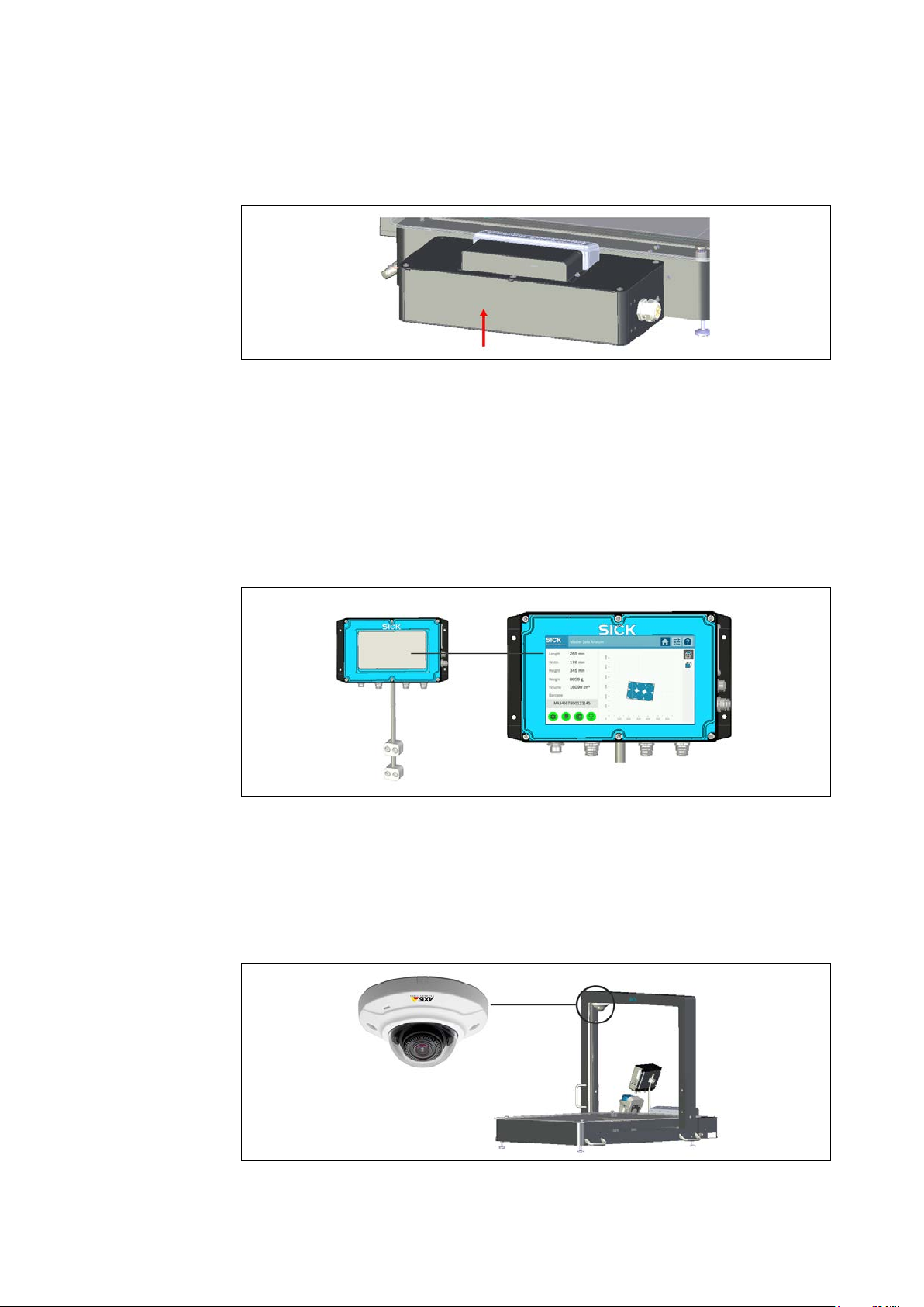
2.4.5 Protective devices
The Master Data Analyzer has been built in a way that allows for safe operation.
Protective devices reduce potential risks to people and the device to the maximum
possible extent.
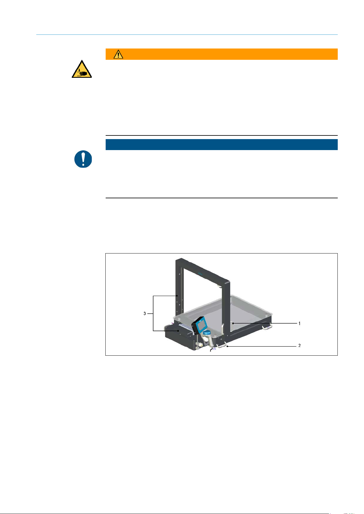
Fig. 1: Protective devices
• Four handles (1) make it easier to unpack and lift the MDA in line with ergonomic
principles.
• Handles (2) allow the measurement gantry to be moved safely over the object to be
measured.
• Cover plates (3) protect cables and electronic components.
Page 18
2 SAFETY
8020065-ZSP4/2017-08-10|SICK
OPERATING INSTRUCTIONS | Master Data Analyzer
Subject to change without notice
18
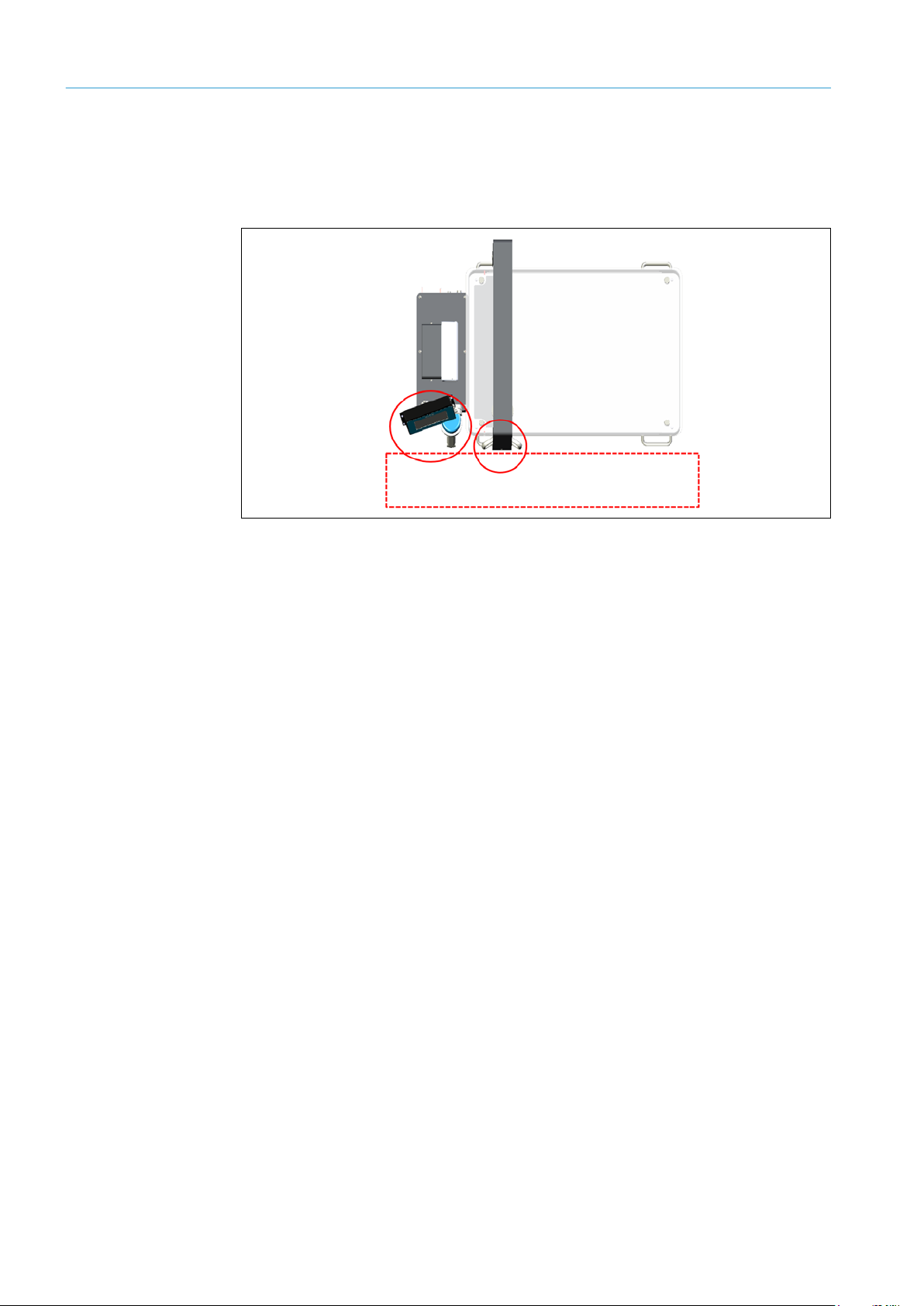
2.4.6 Work station
The work station for measuring objects is located on the side of the display and the handheld scanner. The handles for moving the measurement gantry are also located on this
side.
Fig. 2: Work station
We recommend placing the Master Data Analyzer on a sufficiently stable and steady table
so that the measuring objects can be loaded and unloaded in line with ergonomic
principles. The table must be secured against rolling away.
A sliding table is available as an accessory.
2.4.7 Protective equipment
The operating entity must wear personal protective equipment (PPE) in accordance with
the locally applicable safety regulations.
Personal protective equipment for transport and installation
Wear safety shoes in addition to your basic safety equipment during transport and
▸
installation.
2.4.8 The operating entity’s responsibilities
The operating entity must execute the electrical installation in compliance with the
respective provisions of the local electricity supply company as well as applicable
standards.
The following directive applies to the Master Data Analyzer:
• EMC Directive: 2014/30/EU
Page 19

19
8020065-ZLP4/2017-08-10|SICK
Subject to change without notice
OPERATING INSTRUCTIONS | Master Data Analyzer
2.5 Protecting the environment
The Master Data Analyzer is designed to minimize its impact on the environment. Apart
from the housing, the system contains no materials using silicon.
Always act in an environmentally responsible manner at work. For this reason, please note
the following information regarding disposal.
2.5.1 Power consumption
All components in the Master Data Analyzer are supplied centrally with voltage via a
power cable.
The MDA’s typical power consumption in running operation is around 36 watts.
2.5.2 Disposal after final decommissioning
SICK does not currently take back devices that are unusable or irreparable.
Always dispose of unusable or irreparable devices in an environmentally safe manner in
accordance with the relevant national waste disposal regulations.
Always dispose of unusable or irreparable devices in an environmentally safe manner
▸
in accordance with the relevant national waste disposal regulations.
Dispose of all electronic assemblies as hazardous waste. The electronic assemblies are
▸
easy to dismantle.
Dispose of the controller’s battery separately as per the ROHS directives (Europe).
▸
SAFETY 2
Page 20
3 SYSTEM DESCRIPTION
8020065-ZSP4/2017-08-10|SICK
OPERATING INSTRUCTIONS | Master Data Analyzer
Subject to change without notice
20
Part no.
Description
1079161
Master Data Analyzer MDA650 with a monitoring length of 650 mm
1079162
Master Data Analyzer MDA800 with a monitoring length of 800 mm
1079163
Master Data Analyzer MDA650 Image with a monitoring length of 650 mm
and a fixed IP camera
1079164
Master Data Analyzer MDA800 Image with a monitoring length of 800 mm
and a fixed IP camera
Part no.
Description
2087193
WLAN module with mounting kit for mobile applications
2087216
Sliding table
2087217
Sliding table with built-in rechargeable battery
6062161
Power supply unit
3 System description
This chapter provides information on the special properties of the DWS system. It describes
the design and operating principle of the system solution.
3.1 Scope of delivery
The Master Data Analyzer is available in two different monitoring lengths, each of which is
available with and without an IP camera.
System variants
Tab. 3: System variants
Optional accessories
Note
Tab. 4: Optional accessories
On request, the Master Data Analyzer is available with scales that can be verified.
Verification takes place at the factory.
Operating the scales in LFT mode (Legal for Trade mode) is useful if the logged data are
used for invoicing purposes or if certified accuracy must be ensured.
Page 21
21
8020065-ZLP4/2017-08-10|SICK
Subject to change without notice
OPERATING INSTRUCTIONS | Master Data Analyzer
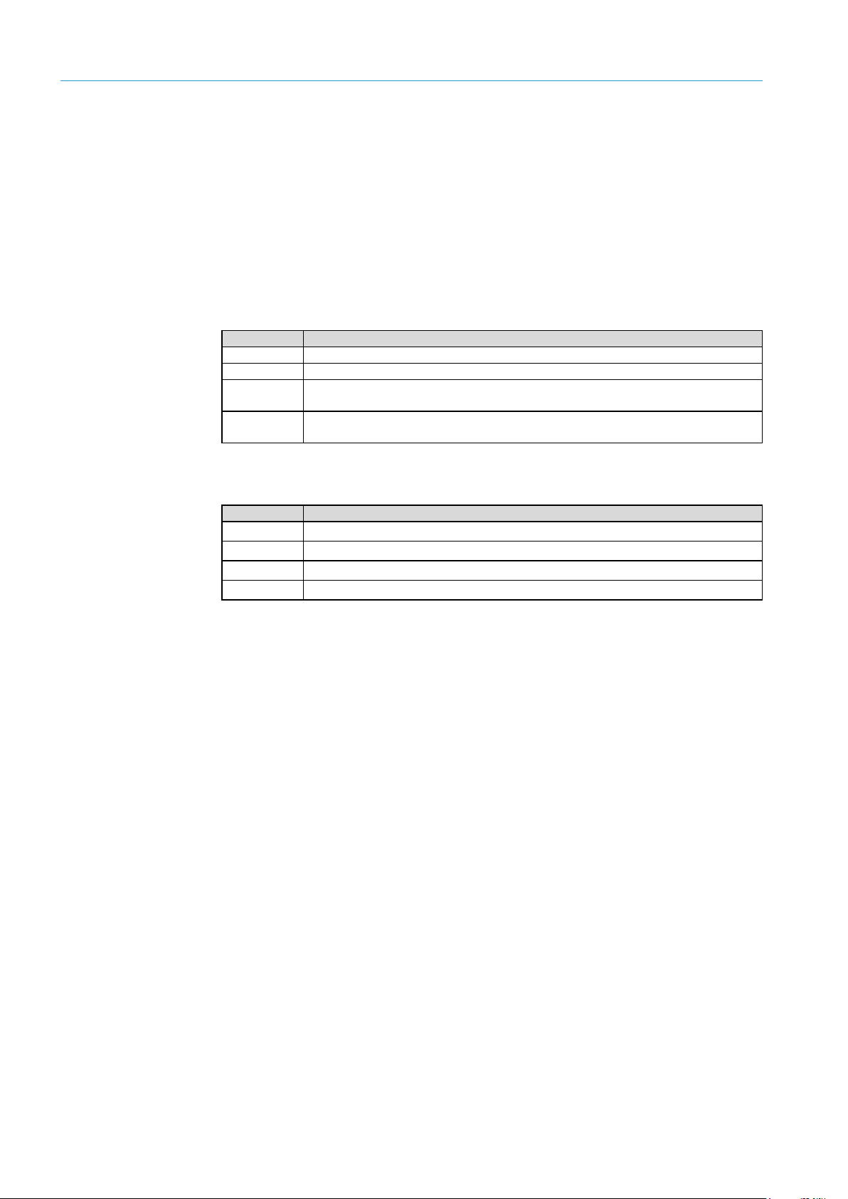
3.2 System components
The Master Data Analyzer consists of:
1. One hand-held scanner for scanning bar code information (only in the operating mode
with bar code scanning).
2. One set of rugged electronic scales with a glass panel for supporting the measuring
object.
3. One moving measurement gantry with two pairs of light grids for recording the
object’s dimensions and a wire draw encoder for calculating the length.
4. One controller for recording the measurement data and emitting the measurement
results to the customer’s system.
5. One display for visualizing the measurement results.
6. One IP camera (only for MDA650 Image/MDA800 Image).
7. One stable mechanism for holding the components
8. One WLAN module available as an accessory for mobile applications of the MDA.
SYSTEM DESCRIPTION 3
Fig. 3: System components
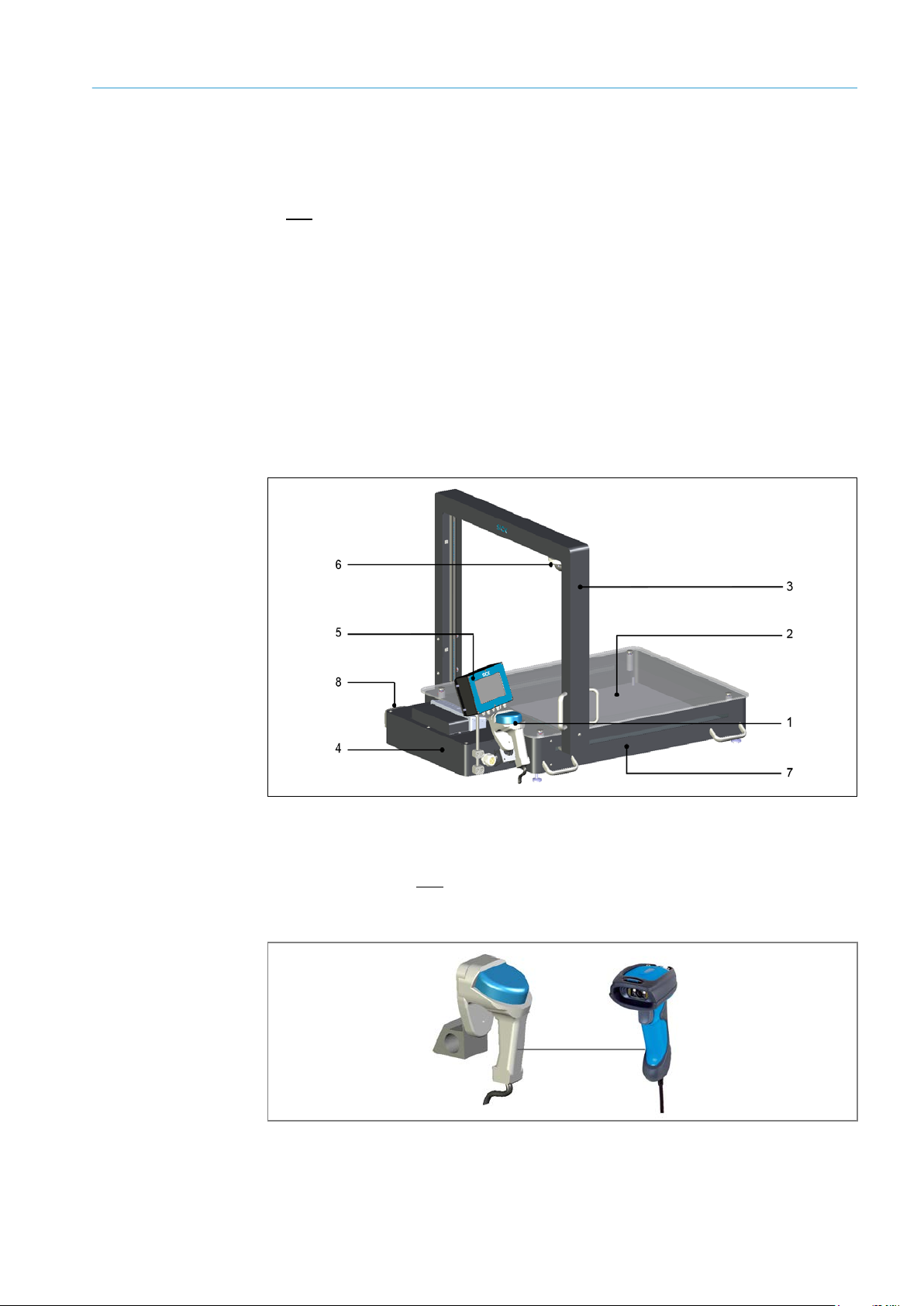
1 – Hand-held scanner
In the operating mode with bar code scanning, the number used to identify the object is
detected using a wired hand-held scanner. The IDM26x hand-held scanner recognizes 1D
and 2D bar codes and all common stacked codes.
Fig. 4: Hand-held scanner
The hand-held scanner is connected to the MDA’s controller by a cable. This cable is used
to both supply the hand-held scanner with voltage and transmit data.
Page 22
3 SYSTEM DESCRIPTION
8020065-ZSP4/2017-08-10|SICK
OPERATING INSTRUCTIONS | Master Data Analyzer
Subject to change without notice
22
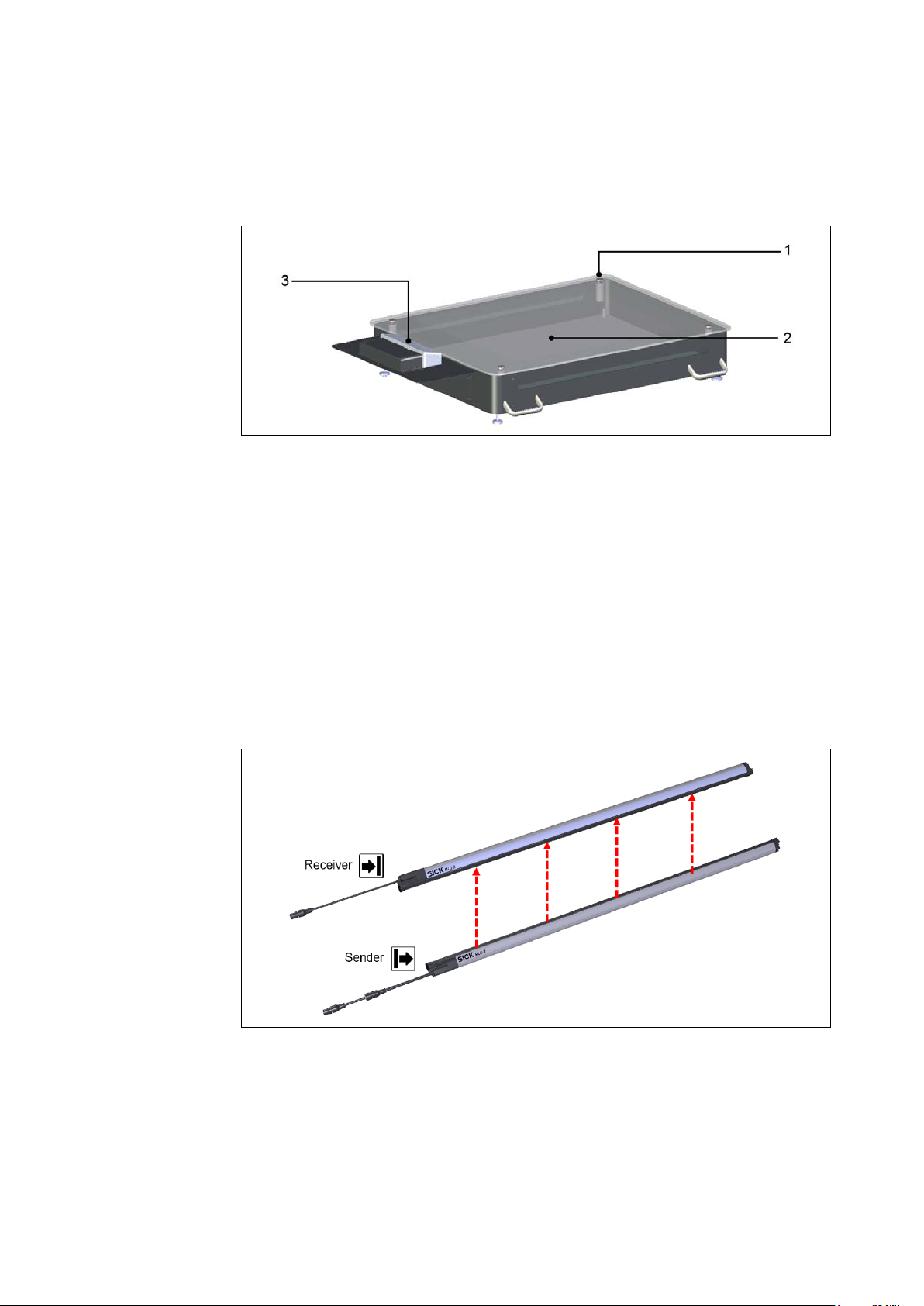
2 – Electronic scales
The electro-mechanical scales consist of a glass panel as the weighing surface (1),
four weighing cells at the corners (2), one electronic evaluating system, and a separate
display (3).
Fig. 5: Electronic scales
Four positioning points are used for measurement. These points transfer the force to the
weighing cells installed on the corners. The glass panel made of safety glass makes sure
the force is distributed evenly on all four corners.
The scales’ display only visualizes the recorded object weight.
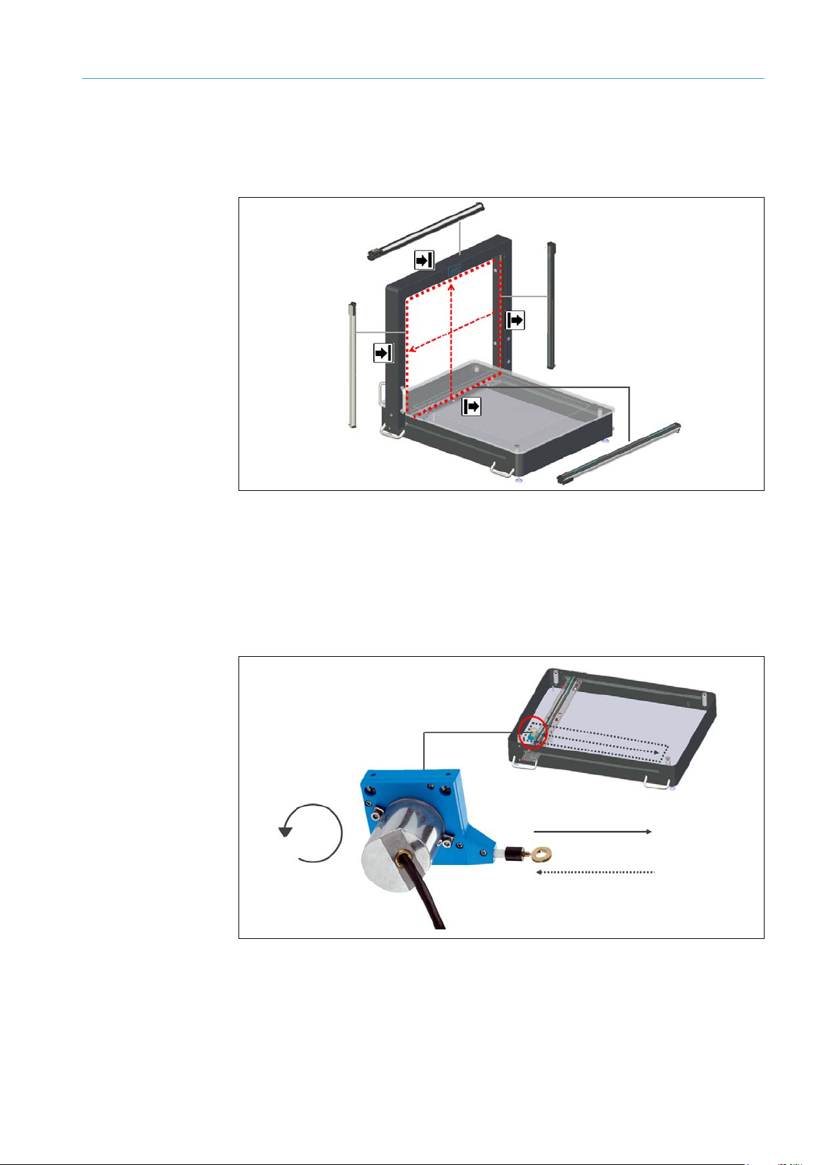
3 – Measurement gantry with MLG-2 light grids and wire draw encoder
The measurement gantry consists of a horizontal and vertical pair of light grids, which are
arranged at right angles. Both pairs of light grids determine the object’s contour based on
the principles of shadows.
Each pair of light grids consists of a sender unit with emitting diodes and a receiver unit
with receiving diodes.
Fig. 6: MLG-2 light grids
Page 23
SYSTEM DESCRIPTION 3
23
8020065-ZLP4/2017-08-10|SICK
Subject to change without notice
OPERATING INSTRUCTIONS | Master Data Analyzer
The horizontal light grid’s is mounted on the frame underneath the glass plate with the
receiver above it. This minimizes any interference caused by ambient light or dirt. The
beam from the lower light grid passes through the glass plate to the upper light grid. The
vertical light grid’s sender is secured to the frame with two handles.
Wire draw encoder
Fig. 7: Measurement gantry with light grids
A wire draw encoder mounted in the housing interior supplies the positional data of the
light grids above the object which is required for measuring lengths. The encoder
transfers the linear movement obtained from the path of the measurement gantry into a
rotational movement. The drum rotation, which is proportional to the length, is output to
the controller via corresponding incremental signals regarding the exact positioning of the
light grids.
Fig. 8: Wire draw encoder
Page 24
3 SYSTEM DESCRIPTION
8020065-ZSP4/2017-08-10|SICK
OPERATING INSTRUCTIONS | Master Data Analyzer
Subject to change without notice
24
4 – Controller MSC800
The controller housing contains the MSC800 system controller and the power supply unit
for the central voltage supply.
Fig. 9: Controller MSC800
The MSC800 is the system’s central control unit. It controls the coordination of the
individual components and processes all incoming signals. The measurement results are
transmitted via the Ethernet interface to the higher-level customer system.
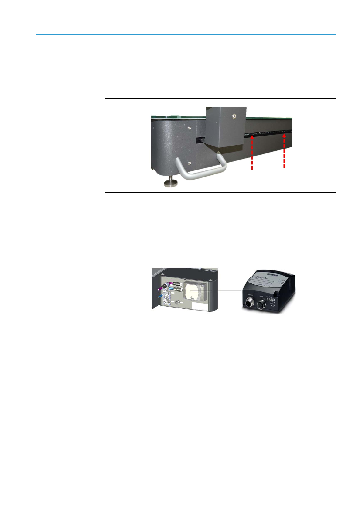
5 – Display
The display is the system’s central visualization unit. It displays the measured values from
the various components during operation and allows for the convenient handling of error
messages.
Fig. 10: Display
6 – IP camera (MDA650 Image/MDA800 Image only)
An IP camera mounted on the measurement gantry generates a photo-realistic image of
the object during the measurement process. The photo is transmitted to the higher-level
customer system together with the measurement data.
The IP camera is supplied with power via PoE (power over Ethernet).
Fig. 11: IP camera (MDA650 Image/MDA800 Image only)
Page 25
SYSTEM DESCRIPTION 3
25
8020065-ZLP4/2017-08-10|SICK
Subject to change without notice
OPERATING INSTRUCTIONS | Master Data Analyzer
7– Housing
All of the Master Power Analyzer’s components are integrated into a stable mechanical
system.
The recesses on the long sides of the housing are required for the measurement gantry to
travel along the linear guides. The recesses are sealed on both sides with brushes.
Fig. 12: Housing
8 – WLAN module
The WLAN Ethernet Port Adapter, which is available as an accessory for the controller
housing, enables the Ethernet interface to be connected wirelessly to a WLAN access
point. This enables measurement results to be transmitted to the customer system when
using the MDA in a mobile setup, regardless of the measurement location.
Fig. 13: WLAN module
The WLAN Ethernet Port Adapter has a circular, polarized 5 dB directional antenna that
also enables it to be used in surroundings with a high number of reflections from metals.
Sliding table
On request, the Master Data Analyzer is available with a sliding table, with or without a
rechargeable battery.
Page 26
3 SYSTEM DESCRIPTION
8020065-ZSP4/2017-08-10|SICK
OPERATING INSTRUCTIONS | Master Data Analyzer
Subject to change without notice
26
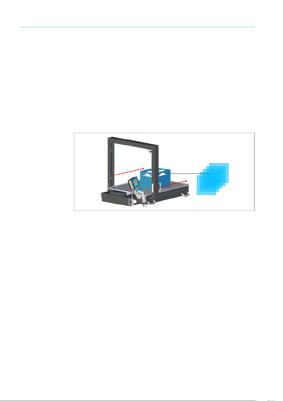
3.3 The system’s operating principle
The Master Data Analyzer is designed for stationary and mobile use, depending on the
system variant.
In the stationary variant, the Master Data Analyzer is placed at a fixed location and
connected (e.g., at the receiving work station). With the mobile variant, data can be
recorded at any chosen location (e.g., right on the high-bay racking). A WLAN adapter
must be connected in this case.
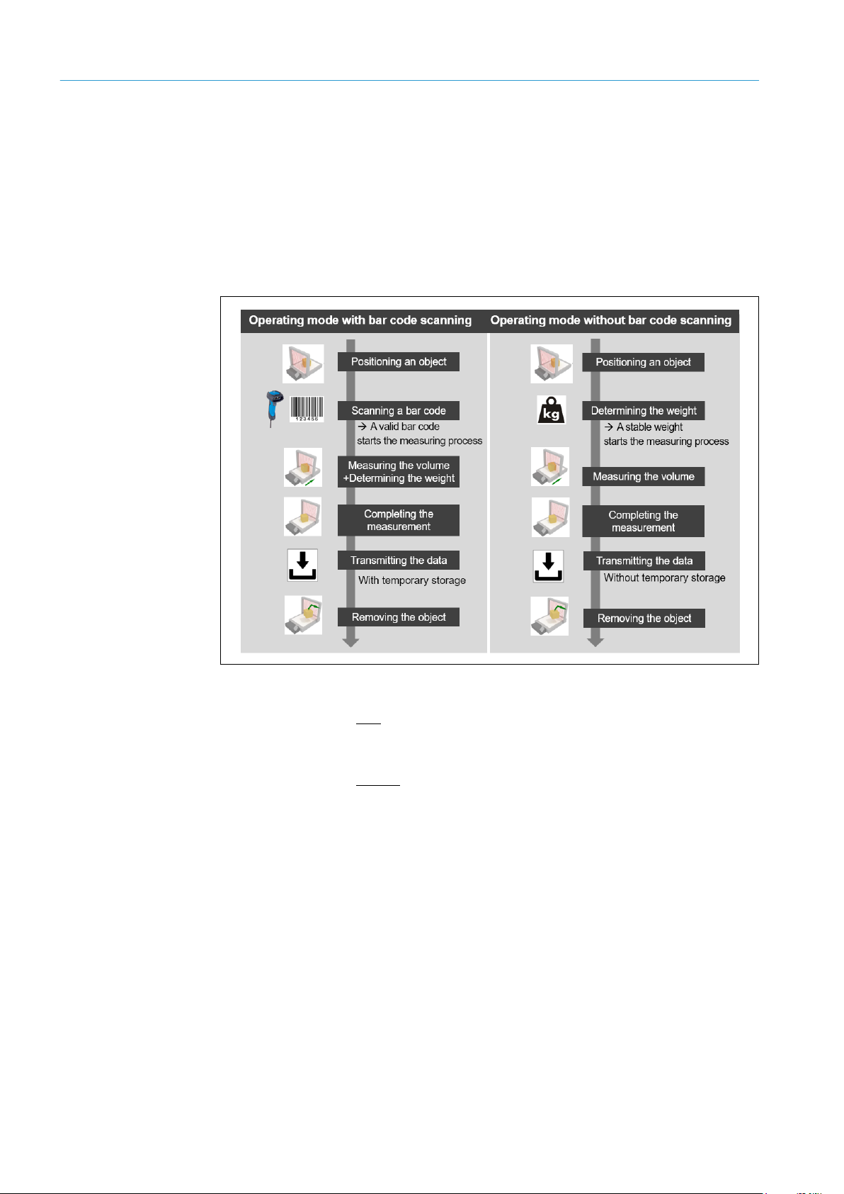
The measurement process depends on the operating mode in question.
Fig. 14: Measurement process for each operating mode
In the operating mode with bar code scanning, the measuring process starts once the
object has been placed on the measurement field and the bar code has been scanned.
The volume and weight are then measured in one procedure.
In the operating mode without bar code scanning, the measuring process starts with the
weight measurement. The volume cannot be measured until a stable weight value is
present.
Page 27
SYSTEM DESCRIPTION 3
27
8020065-ZLP4/2017-08-10|SICK
Subject to change without notice
OPERATING INSTRUCTIONS | Master Data Analyzer
Placing an object in the measurement field
The measurement object is placed in the clear-glass area of the glass plate. This area
marks the measurement field, i.e., the area in which the object can be captured by the
light grids. If the object, or any part of it, is outside of the measurement field (in the opal
glass area) an error message will be issued.
Fig. 15: Marked measurement field on the glass panel
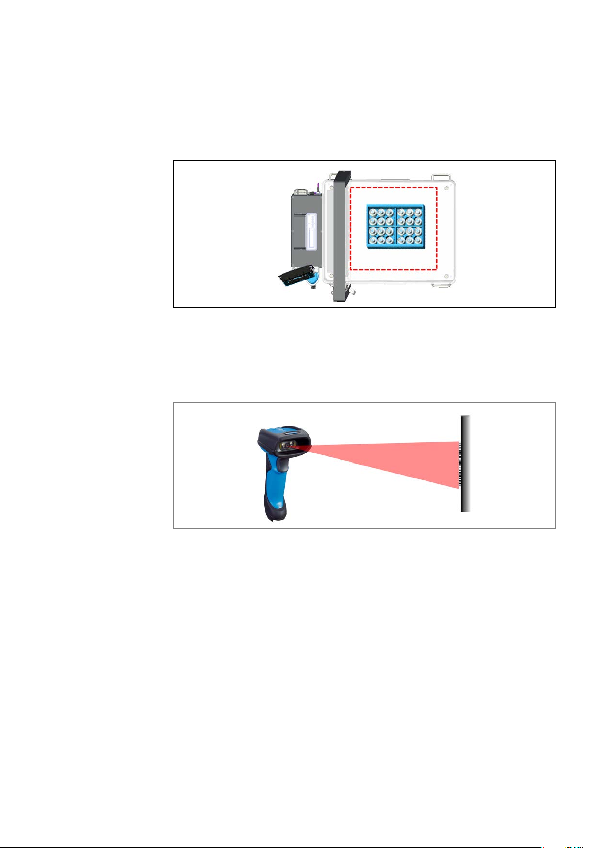
Bar code reading (only for operating mode with bar code scanning)
The wired hand-held scanner identifies the object and transmits the shipping number to
the controller. The scanner creates a scan line on the object to read the bar code using a
red light. The bar code that is read is then shown on the display.
Fig. 16: Operating principle – bar code reading
Note
The bar code can also be entered manually using the display.
Weight measurement (only for operating mode with bar code scanning)
In the operating mode without bar code scanning, the measuring process starts with the
system detecting a stable weight value. Bar codes cannot be scanned or processed.
Page 28
3 SYSTEM DESCRIPTION
8020065-ZSP4/2017-08-10|SICK
OPERATING INSTRUCTIONS | Master Data Analyzer
Subject to change without notice
28
Measuring the volume
The volume measurement is carried out if a valid bar code or stable weight value is
available.
To do so, the light grids mounted on the measurement gantry are manually moved over
the measurement object using the two linear guides. Measurements can be taken in both
directions, stopped whilst doing so, and then recommenced.
If the monitoring field is interrupted by an object, the shadowing and the resulting number
of interrupted light beams on the receiver lines can be used to detect the profile of the
object.
The change in the number of beams on the receiver lines as a result of the shadowing is
transmitted via the light grids’ interfaces to the MSC800 as a digital signal.
Two-dimensional cross sections are created by moving the light grids across the object.
The controller then combines the individual 2D cross sections of the object.
Fig. 17: Operating principle – volume measurement
By taking into consideration the speed with which the measurement gantry is moved
across the object and the respective position of the light grids above the object, a spatial
image is produced which is used to calculate the smallest possible cuboid which could
surround the object as well as its volume.
Page 29
SYSTEM DESCRIPTION 3
29
8020065-ZLP4/2017-08-10|SICK
Subject to change without notice
OPERATING INSTRUCTIONS | Master Data Analyzer
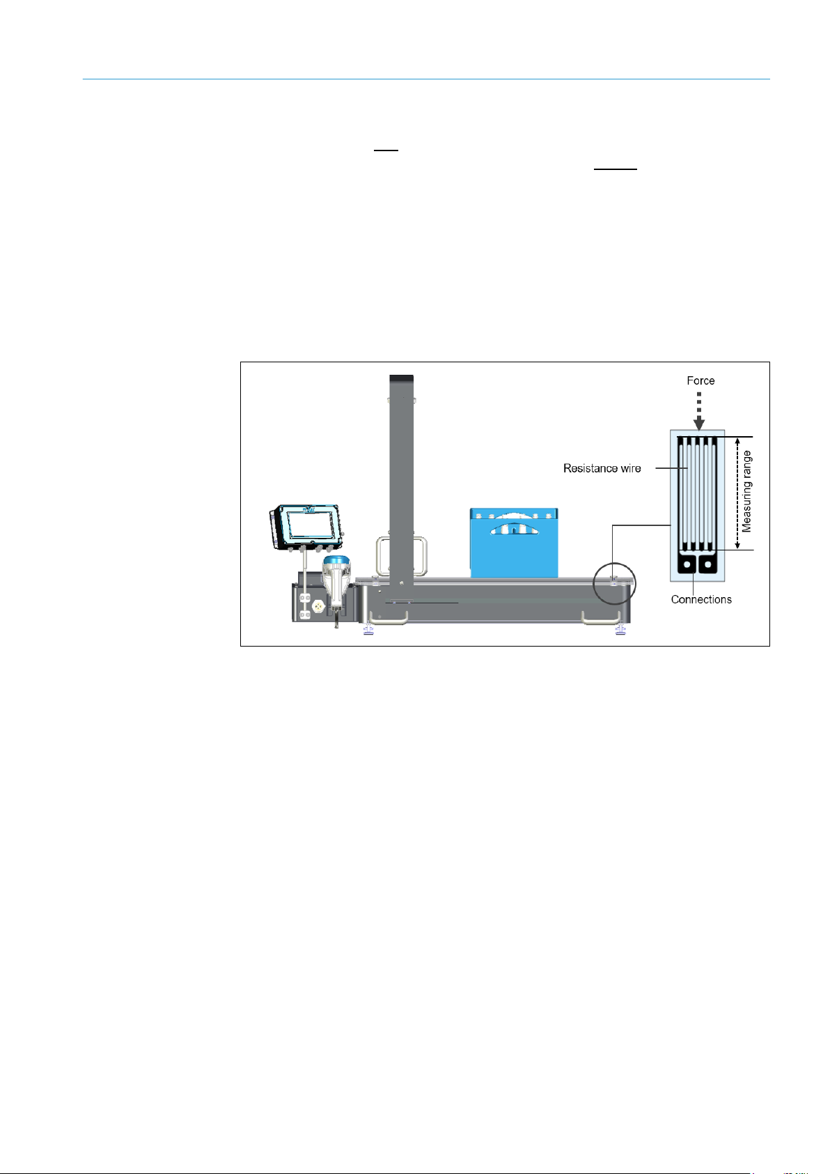
Weighing process
In the operating mode with bar code scanning, the weighing process takes place in
parallel to the volume measurement; in the operating mode without bar code scanning,
the weight is calculated once the object has been positioned, i.e., before the volume
measurement.
The weighing cells determine the weight of the object by using the four recording points at
the corners of the glass panel whilst the object is situated on the glass panel.
The electronic scales use weighing cells with strain gauges to bear the weight to be
measured. Strain gauges are metallic conductors which convert mechanical actions of
force into an electronic signal. Strain gauge weighing cells use the physical principle that
an electrical conductor changes its electrical resistance as a result of mechanical
changes.
Fig. 18: Operating principle – Weighing process
If a load is placed on the glass panel, this causes the strain gauges to deform. As a result
of this deformation causing the resistance in the strain gauges to change, the weight of
the load can be determined by using the electronic scales. The greater the deformation,
the greater the resistance due to the strain and, as a result, the heavier the weight of the
measured object.
In order to achieve maximum measurement accuracy, the electronic signal resulting from
the change in resistance is converted to a digital signal by an integrated A/D converter
(analog-digital transducer).
The weight recorded is then shown on the display. It is added to the bar code already
displayed.
If the weight value of an object is outside of the pre-configured absolute limit values, this
is output as an error in the measurement report.
Page 30

3 SYSTEM DESCRIPTION
8020065-ZSP4/2017-08-10|SICK
OPERATING INSTRUCTIONS | Master Data Analyzer
Subject to change without notice
30
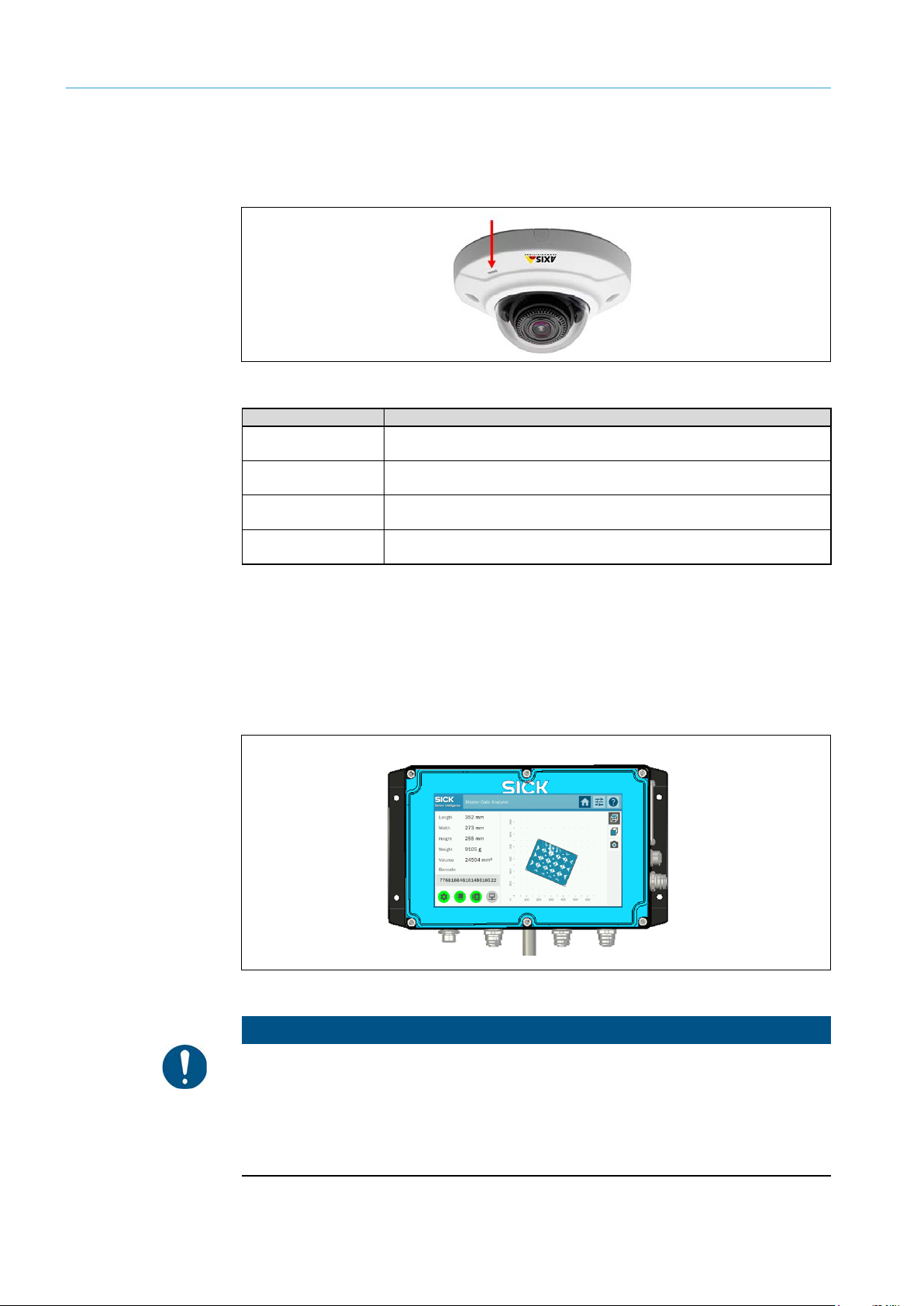
Visualization of measurement results
All of the measurement data recorded by the MDA is constantly shown on the display. The
measurement is additionally displayed in the form of a 2D visualization.
If the MDA650 Image / MDA 800 Image system variant is in use, the symbol for the live
display appears on the right, next to the measurement field.
Fig. 19: Operating principle – Visualization of measurement results
Output of measured values
All information converges in the MSC800 central control unit. The MSC800 processes the
encoder signals and assigns the measurement results from the individual systems to the
respective object.
Depending on the system variant, the output of measured values are sent to the higherlevel customer system via Ethernet (LAN) or via a WLAN access point.
When using the MDA650 Image/MDA800 Image), a photo-realistic image of the
measuring object can be emitted with the measurement results.
Note
• In the operating mode with bar code scanning, the measurement results are stored
temporarily during the output of measured values if the device is not connected to
the customer server. This allows multiple measurements to be carried out in sequence,
even without a connection. Data are transmitted automatically as soon as the
connection is available again.
• In the operating mode without bar code scanning, the data must be transferred directly
after the measurement otherwise the data cannot be allocated to the bar code in
the customer system. The temporary storage of measurement results is not supported.
Page 31

31
8020065-ZLP4/2017-08-10|SICK
Subject to change without notice
OPERATING INSTRUCTIONS | Master Data Analyzer
3.4 Project planning
Dimension
Explanation
Minimum object size (L x W x H)
10 mm x 10 mm x 5 mm
Maximum object size (L x W x H)
MDA800 / MDA800 Image
800 mm x 600 mm x 600 mm
Object rotation
Omni
Minimum object weight
20 g
Maximum object weight
30,000 g
Singulation
Yes
System requirements
The following conditions must be met to operate the Master Data Analyzer:
• Supply voltage: AC 100 to 264 V/50 to 60 Hz
• Ethernet connection of WLAN access point for forwarding the measurement results
to the customer’s system
Requirements for the operation site
• Closed room
• Flat and firm surface
• Low-vibration environment
• Protected from wind and free of drafts
• Well-lit
• Clean and dry
• Room temperature below 40 °C
Regardless of the space requirements of the MDA, there must be enough space at the
operation site for the following activities:
• Operating the system
• Cleaning, repair, and service
Ethernet connection requirements
In the operating mode without bar code scanning, a permanent Ethernet connection
must be in place otherwise the measurement results will not be able to be assigned to the
bar code in the customer’s system.
Object requirements
SYSTEM DESCRIPTION 3
Notes
MDA650 / MDA650 Image
Tab. 5: Conveying system and object requirements
650 mm x 600 mm x 600 mm
If the object moves suddenly or vibrates on the MDA during the measurement process,
the accuracy may be reduced and less data may be recorded by the system.
Page 32

3 SYSTEM DESCRIPTION
8020065-ZSP4/2017-08-10|SICK
OPERATING INSTRUCTIONS | Master Data Analyzer
Subject to change without notice
32
No.
LED indicator
Description
1
Green
Green LED permanently on
Supply voltage on
1
Red
Red LED permanently on
Hardware fault
No.
LED indicator
Description
1
Green
Green LED permanently on
Supply voltage on
Green
Green LED off
Supply voltage off or too low
2
Yellow
Yellow LED permanently on
Light path interrupted (at least one beam is interrupted)
Yellow
Yellow LED off
Light path is unobstructed
Yellow 3 Hz
Yellow LED flashing rapidly
The alignment mode is not permanently deactivated until after teach-in
Yellow 1 Hz
Yellow LED flashing slowly
Teach-in active
Red
Red LED permanently on
combination of the yellow and the green LEDs.
Red 10 Hz
Red LED flashing rapidly
An error has occurred during teach-in.
3.5 Status indicators
The Master Data Analyzer’s accessible status indicators can be found on the following
devices:
3.5.1 Status indicators – Light grids
The receivers on the light grids have three LEDs on the connection side. These provide a
visual indication of the operational status and any occurring faults.
Fig. 20: Status indicators – Light grids
LEDs on the MLG-2 sender
Tab. 6: Status indicators – Light grids (senders)
LEDs on the MLG-2 receiver
Contamination warning or alignment mode is active (the signal from
the receiver is too weak)
A fault has occurred. The type of fault will be indicated by a
Tab. 7: Status indicators – Light grids (receivers)
Page 33

SYSTEM DESCRIPTION 3
33
8020065-ZLP4/2017-08-10|SICK
Subject to change without notice
OPERATING INSTRUCTIONS | Master Data Analyzer
LED indicator
Description
Blue
LED is permanently blue: Supply voltage on
Green
LED flashes green once: The bar code has been scanned successfully
Indicator
Description
Beeper
1 beep following successful scan.
Vibration
Vibration following successful scan.
3.5.2 Status indicators – Hand-held scanner (only in operating mode with bar code scanning)
Optical indicators
The wired hand-held scanner has an LED to display the operational and reading status.
Fig. 21: Status indicators – Hand-held scanner
Tab. 8: Status indicators – Hand-held scanner
Further indicators
Page 34
3 SYSTEM DESCRIPTION
8020065-ZSP4/2017-08-10|SICK
OPERATING INSTRUCTIONS | Master Data Analyzer
Subject to change without notice
34
LED indicator
Description
LED is off
Connection and normal operation
Green
Permanently green for 10 seconds for normal operation following system
start
Yellow
Permanently on during start-up.
Flashes during firmware update.
Yellow/red
Flashes yellow/red if the network connection is not available or has been
lost.
NOTE
3.5.3 Status indicators – IP camera
The IP camera mounted to the measurement gantry for the MDS650/800 is equipped
with a status LED.
Fig. 22: Status indicators – IP camera
Tab. 9: Status indicators – IP camera
3.5.4 Status indicators – Display
The display is used to visualize the measurement results as well as for interacting with the
system to troubleshoot error messages.
The screen is controlled by gently touching the respective touch pads. The touch pads on
the touch screen vary according to the operational context.
Fig. 23: Status indicators – Display
Notes on the correct use of the touch screen
You are only permitted to touch the touch screen with your fingers. Gently press the touch
pads to operate them; do not apply force.
Do not operate the touch screen with pointed or sharp objects; otherwise, the surface of
the touch screen will become damaged.
Page 35

35
8020065-ZLP4/2017-08-10|SICK
Subject to change without notice
OPERATING INSTRUCTIONS | Master Data Analyzer
3.5.5 Status indicators – Electronic scales
Designation
Color
Status
Description
PWR
Green
On
Supply voltage is on
Flashing
Supply voltage is too low
Off
Supply voltage is not on
>>>
Blue/purple/red
Blue light
A WLAN connection has been established
Purple
The device is attempting to connect to
another WLAN device
Flashing blue
Data transmission
Red
Fault
Off LAN
Yellow
On
Ethernet link available
Flashing
Ethernet communication is active
Off
No Ethernet connection
Designation
Color
Status
Description
Link quality
Green
On
A: Weak connection quality
A, B, C, D: Excellent connection quality
The scales display affixed to the controller housing only shows the measurement results
from the electronic scales.
The additional display is required if the MDA’s electric scales are to be operated in the
verified mode.
3.5.6 Status indicators – WLAN module
The WLAN module which can be added as an optional accessory has the following status
and diagnostics displays.
SYSTEM DESCRIPTION 3
Fig. 24: Status indicators – WLAN module
Tab. 10: Status indicators – WLAN module
Quality
Four LEDs are located on the underside of the device which display different information
depending on the operating mode.
A and B: Sufficient connection quality
A, B, and C: Good connection quality
Tab. 11: Status indicators – WLAN module (quality)
Page 36

3 SYSTEM DESCRIPTION
8020065-ZSP4/2017-08-10|SICK
OPERATING INSTRUCTIONS | Master Data Analyzer
Subject to change without notice
36
Name
Description
The measurement results are transmitted to the customer’s higher-level system
configured for this interface.
The separate Service configuration interface is available for configuring the
system.
3.6 Interfaces
The Master Data Analyzer has two Ethernet interfaces.
Data
Service
Tab. 12: MSC800 Ethernet interfaces
using the Data Ethernet data interface. The TCP/IP and FTP protocols can be
Page 37

TRANSPORT, ASSEMBLY, AND MOUNTING 4
37
8020065-ZLP4/2017-08-10|SICK
Subject to change without notice
OPERATING INSTRUCTIONS | Master Data Analyzer
Icon
Meaning
Transport the crate with this side facing up!
The contents of this transport crate are fragile!
Keep dry!
Do not place anything on top of this box!
4 Transport, assembly, and mounting
All system components are delivered assembled and cabled to each other.
The system must be transported by the customer to the place of utilization.
It can then be removed from the box, put into position, and operated.
4.1 Accepting the delivery
4.1.1 Packaging
The Master Data Analyzer is delivered in a strong wooden crate on a transport pallet.
This protects the system against the impacts of transportation such as sudden jolts and
knocks, dirt and dust or moisture such as rain, snow or condensed water throughout
the entire transportation process, during loading and unloading, and whilst in storage.
Signs with notes ensuring secure transportation
The packaging bears signs with notes to ensure the system is securely transported and
appropriately stored. These symbols must be observed.
Tab. 13: Signs with notes ensuring secure transportation
4.1.2 Checking delivery for visible transport damage
The package should be checked immediately after unloading to ensure all items have
been delivered by using the delivery note as well as checking for any external damage.
If visible external transport damage is discovered on receipt of the package, we
recommend you take the following action:
Visible damage
Immediately record the discovered transport damage in the freight documents and
▸
ask the delivery carrier to countersign this.
In the event of serious damage, the manufacturer and insurance company should be
▸
notified immediately.
Do not attempt to make any changes to the damage from when it is discovered and
▸
keep the packaging material until the transport company or transport insurance
company have come to a decision whether to visit your location.
If possible, take photos of the damage to packaging and packaged goods.
▸
Page 38

4 TRANSPORT, ASSEMBLY, AND MOUNTING
8020065-ZSP4/2017-08-10|SICK
OPERATING INSTRUCTIONS | Master Data Analyzer
Subject to change without notice
38
WARNING
4.2 Transporting the MDA to its location of use
It is best to transport the package in its packaging until you reach the location where the
device is to be used.
The transport crate must always be kept upright and in a horizontal position when being
transported.
Under no circumstances, and not even for a short time, should it be turned over or stored
on its side.
Risk of injury from suspended load
The Master Data Analyzer is delivered in a transport crate on a pallet. Use a suitable lifting
device to unload and transport the device.
During transport, tipping or falling loads pose a risk of severe injury or damage to
property.
Measures
Only use lifting equipment which is suitable for the weight and dimensions of the
▸
freight.
Make sure that the center of gravity is in the center between the forks of the lifting
▸
device and the forks are completely entrenched under the transport pallet.
Do not stop underneath the suspended load.
▸
Wear safety shoes in addition to your personal protective equipment.
▸
Note
Transport with manned forklift truck/lifting truck
Use a manned forklift truck or a suitable lifting truck to transport the crate.
1. Pick up the pallet with the forks.
Make sure that the center of gravity is in the center between the forks and the forks
▸
are completely entrenched under the transport pallet.
Fig. 25: Transporting with a lifting device
2. Transport the load to the place of use.
3. Carefully set down the pallet at the operation site.
Page 39

TRANSPORT, ASSEMBLY, AND MOUNTING 4
39
8020065-ZLP4/2017-08-10|SICK
Subject to change without notice
OPERATING INSTRUCTIONS | Master Data Analyzer
NOTE
WARNING
WARNING
WARNING
4.3 Unpacking and setting up the device
4.3.1 Unpacking the MDA
Instructions for unpacking can be found on the outside of the transportation crate which
is used to deliver the device.
While unpacking, follow all stages in the unpacking instructions.
▸
All work relating to the installation of the device must only be done in consideration of the
relevant safety regulations.
Risk of injury due to components falling over
The side panels and lid of the transport crate are heavy and difficult to handle.
Falling objects pose a risk of crushing during dismantling.
Measures
Always use 2 people to mount the side panels and lid.
▸
Wear protective shoes in addition to your personal protective equipment.
▸
Risk of injury when lifting heavy objects.
There is a risk of injury when lifting heavy objects.
Depending on the system variant, the MDA weighs around 65 kg to 80 kg.
Measures
Use 4 people to lift the MDA.
▸
In order to do this, use the four handles on the two long sides of the MDA.
▸
Lift and carry the MDA according to ergonomic principles.
▸
Wear protective shoes in addition to your personal protective equipment.
▸
Impermissible handling of the device
There is a risk of damage to the device when lifting the MDA using the measurement
gantry.
Measures
Do not lift the MDA using the measurement gantry under any circumstances!
▸
Disassembling the transport crate
The lid and side panels are secured with screws.
1. Unscrew and remove the screws from the lid and lift the lid from the transportation crate.
2. Unscrew and remove the screws in order from the four side panels and then remove
them.
3. The Master Data Analyzer can now be accessed from all sides.
Page 40

4 TRANSPORT, ASSEMBLY, AND MOUNTING
8020065-ZSP4/2017-08-10|SICK
OPERATING INSTRUCTIONS | Master Data Analyzer
Subject to change without notice
40
NOTE
NOTE
Removing the device from the pallet
1. Remove all of the secondary packaging.
2. Use 4 people to each hold the MDA by one of the handles on the long side of the
housing.
Fig. 26: Lifting the MDA from the transport pallet
3. Lift the device straight from the pallet taking ergonomic aspects into account.
Storing packaging
The packaging should be kept for the period of the warranty.
The steps should be repeated in reverse order if the package is to be sent back.
Disposing of the packaging
The packaging used for the Master Data Analyzer is made from wood and plastic.
The customer is responsible for proper disposal of the packaging.
The national regulations at the operation site must be observed.
4.3.2 Checking delivery for hidden transport damage
We recommend that the MDA is thoroughly checked for all types of (hidden) transport
damage once it is unpacked. Any damage should then be reported.
All components should be examined for mechanical damage.
▸
Inspect all cableways to the connected components.
▸
Check that all cable connections are securely attached.
▸
Note
Always document the damage by taking photographs.
▸
Page 41

41
8020065-ZLP4/2017-08-10|SICK
Subject to change without notice
OPERATING INSTRUCTIONS | Master Data Analyzer
4.3.3 Setting up the MDA
WARNING
WARNING
The Master Data Analyzer is set up on a table.
Risk of injury due to the device tipping over
There is a risk of the MDA tipping over during installation. An unsuitable surface may also
lead to the device tipping over.
The device tipping over can lead to the severe crushing or even loss of limbs.
There is also the risk of inflicting damage to the device.
Measures
Place the device on a sufficiently stable and steady table.
▸
Secure the table to prevent rolling away.
▸
All four of the adjustable feet must be completely on the table.
▸
TRANSPORT, ASSEMBLY, AND MOUNTING 4
Risk of crushing when settings down the MDA
The adjustable feet are designed so that the safety distance between the bottom of the
device and the tabletop can be observed.
There is a risk of crushing when installing the MDA on the tabletop.
Measures
Do not put your hands under the base of the housing when installing the MDA.
▸
Fig. 27: Risk of crushing when settings down the MDA
Page 42

4 TRANSPORT, ASSEMBLY, AND MOUNTING
8020065-ZSP4/2017-08-10|SICK
OPERATING INSTRUCTIONS | Master Data Analyzer
Subject to change without notice
42
Placing the MDA on a table
1. Put the MDA with the four adjustable feet on a table. The table must be stable, of a
sufficient size and secured against rolling away.
A non-slip base is recommended.
Note
Note
Make sure that all four adjustable feet are completely on the tabletop.
2. Align the Master Data Analyzer. You can use a spirit level or the spirit level visible on
the interior housing to do this.
A sliding table is available as an accessory with or without a rechargeable battery (see
also chapter 3.1 Scope of delivery).
The sliding table is equipped with an anti-slip surface as standard.
Page 43

43
8020065-ZLP4/2017-08-10|SICK
Subject to change without notice
OPERATING INSTRUCTIONS | Master Data Analyzer
4.4 Removing the transport locks
CAUTION
The scales, measurement gantry, and hand-held scanner are protected against damage
whilst being transported.
The transport locks must be removed before commissioning the MDA.
Removing the transport lock on the electronic scales
The glass panel is locked to the housing in order to protect the weighing cells.
1. Unscrew the screws in the transport locks. The non-removable screws cannot be
completely unscrewed.
2. Swivel the transport locks downwards and tighten the screws once again. The transport
locks remain on the housing and can be returned to their initial position in case the
device is transported again.
TRANSPORT, ASSEMBLY, AND MOUNTING 4
Fig. 28: Removing the transport locks on the electronic scales
Removing the transport lock on the measurement gantry
The measurement gantry is secured to the handle with a cable tie on the operator’s side.
Use a suitable tool to cut the cable tie (e.g., wire cutters).
▸
Removing the transport lock on the hand-held scanner
The hand-held scanner is secured in its holder with a cable tie.
Use a suitable tool to cut the cable tie (e.g., wire cutters).
▸
Risk of damage to the connecting cables
The connecting cable is attached together with the hand-held scanner.
When cutting the cable tie, please take care not to damage the connecting cable for
▸
the hand-held scanner.
Page 44

4 TRANSPORT, ASSEMBLY, AND MOUNTING
8020065-ZSP4/2017-08-10|SICK
OPERATING INSTRUCTIONS | Master Data Analyzer
Subject to change without notice
44
4.5 Mounting
4.5.1 Ready to go
All components of the Master Data Analyzer are attached to the housing with mounting
kits and are cabled together. The light grids are mounted in the gantry and aligned with
each other. The hand-held scanner is ready for operation in its holder.
If you are using the MDA650 Image/MDA800 Image, the IP camera is pre-installed on
the upper frame of the measurement gantry.
No further mounting work is required.
4.5.2 Mounting the WLAN module
A WLAN module is available as an accessory for mobile use of the Master Data Analyzer.
The WLAN module is mounted directly onto the housing of the MDA.
The MDA housing wall has two drill holes with the required spacing on the connection side
to accommodate the WLAN module. Two fixing screws are included with delivery for this
purpose.
Fig. 29: Mounting the WLAN module
Mounting
1. Place the WLAN adapter with the two drill holes over the drill holes on the MDA housing.
2. Fasten the device with the two fixing screws.
Page 45

45
8020065-ZLP4/2017-08-10|SICK
Subject to change without notice
OPERATING INSTRUCTIONS | Master Data Analyzer
5 Electrical installation
HAZARD
All components of the Master Data Analyzer are connected with each other at the factory.
The system only needs to be connected to the voltage supply.
Risk of injury due to electrical current
The Master Data Analyzer is connected to the power supply (AC
100 to 264 V/50 to 60 Hz).
Only a qualified electrician or trained person working under the guidance and supervision
of a qualified electrician is permitted to work on electrical systems or equipment, and they
must comply with the electrical regulations.
Improper handling of live devices may lead to severe personal injury or death by electric
shock.
Measures
Electrical installation and maintenance work must only be performed by electrically
▸
qualified personnel.
Standard safety requirements must be met when carrying out any work on electrical
▸
systems or equipment.
Do not touch any live parts.
▸
In the event of danger, immediately disconnect the device from the grid.
▸
Electrical connections may only be made or disconnected when there is no power in the
▸
system.
Only switch on the supply voltage when the connection tasks have been completed and
▸
the wiring has been thoroughly checked.
Only carry out maintenance and repair work when the power is off.
▸
Always use original fuses with the specified current rating.
▸
ELECTRICAL INSTALLATION 5
Page 46

5 ELECTRICAL INSTALLATION
8020065-ZSP4/2017-08-10|SICK
OPERATING INSTRUCTIONS | Master Data Analyzer
Subject to change without notice
46
No.
Connection
Description
1
+24 V DC
MDA voltage supply
2
Service
Ethernet connection for the configuration PC
3
Data
Ethernet connection for transmitting the measurement
results to the higher-level customer system
4
WLAN power
Voltage supply to the WLAN module (optional)
5.1 Connections on the MDA
5.1.1 Components connected as standard
If the Master Data Analyzer is operated in the mode with bar code scanning, the handheld scanner and display are already connected to the controller upon delivery. The
components’ connecting cables are fed into the controller’s housing interior with the
M cable gland.
The hand-held scanner is connected via a cable. The display is connected to the controller
via two separate cables (voltage supply and Ethernet).
Fig. 30: Hand-held scanner connected as standard
MDA650 Image/
MDA800 Image
The IP camera is also already connected for the MDA650 Image/MDA800 Image
devices. The connecting cable is fed into the controller housing by the drag chain in the
housing interior.
5.1.2 Connections on the controller housing
The connection to the voltage supply and the company network must be established
manually.
Fig. 31: Connections on the controller housing
The following plug connections are available on the MDA.
Tab. 14: Connections on the controller housing
Page 47

47
8020065-ZLP4/2017-08-10|SICK
Subject to change without notice
OPERATING INSTRUCTIONS | Master Data Analyzer
5.2 Connecting the MDA to the supply voltage
No.
Description
1
Power supply unit
2
Cable with M12 plug connector for connection to the MDA.
3
Cable with male connector for connection to the power network.
The delivery includes adapters for all types of male connectors used around the world.
HAZARD
The Master Data Analyzer is voltage and frequency dependent and must therefore be
supplied with the correct mains connection for the device. This connection supplies
voltage to the controller and all of the components connected to it.
The connecting cables included in the delivery consist of a power supply unit and two
connecting cables. The power supply unit and cables are packaged separately and
delivered loose in the package.
Tab. 15: Power supply unit with connecting cables
Check voltage information before connection
Before connecting the device to the energy grid, check whether the required voltage
information as per the technical data match the mains voltage at the installation site.
If this is not the case, you must not establish the connection!
Only connect the device using the supplied power cable and to a grounded power
▸
socket with protective contact.
ELECTRICAL INSTALLATION 5
Creating connections
Fig. 32: Connecting the MDA to the voltage supply
1. Connect the M12 female connector for the cable feeding out of the power supply unit
to the 24 V DC male connector on the MDA.
2. Tightly screw in the plug connector.
3. Use the cable with the male connector to establish a connection to the local power
network.
Page 48

5 ELECTRICAL INSTALLATION
8020065-ZSP4/2017-08-10|SICK
OPERATING INSTRUCTIONS | Master Data Analyzer
Subject to change without notice
48
5.3 Connecting the MDA to the target network
Data is transmitted to the target network using the Data Ethernet interface as standard.
The Ethernet cable is not included with the delivery.
Creating connections
Fig. 33: Connecting the MDA to the Ethernet
1. Plug the Ethernet cable’s RJ45 male connector into the Data female connector on the
MDA.
2. Route the cable to a free Ethernet female connector for the target network.
3. Establish the Ethernet connection to the target network.
5.4 Connecting the sliding table with rechargeable battery
If you would like to operate the Master Data Analyzer on the sliding table with an integrated
rechargeable battery, the MDA should be connected to the battery rather than the mains
voltage supply.
An unconnected cable end has been fed out of the rechargeable battery for the connection.
The cable end has an M12 plug connector.
1. Connect the M12 female connector for the cable feeding out of the rechargeable
battery to the 24 V DC male connector on the MDA.
2. Screw in the plug connector.
3. Make sure the connection is secure.
Page 49

49
8020065-ZLP4/2017-08-10|SICK
Subject to change without notice
OPERATING INSTRUCTIONS | Master Data Analyzer
5.5 Connecting the WLAN adapter
The WLAN module that is available as an accessory is connected to the supply voltage
and MDA’s data interface.
Both connections are established using the connecting cables included with the delivery.
Fig. 34: Connecting the WLAN adapter
Connecting the supply voltage
The connecting cable for the supply voltage has an M12 plug connector on both sides.
1. Connect the M12 female connector on the WLAN adapter to the Power male
connector.
2. Connect the other end of the cable to the WLAN Power M12 female connector on the
MDA.
3. Connect the two plug connectors and make sure the connection is secure.
Connecting the Ethernet interface
The cable has an M12 male plug connector on one side for the connection to the WLAN
module and an RJ45 male connector on the other side for the connection to the MDA.
1. Connect the M12 male connector on the WLAN adapter to the LAN male connector.
2. Connect the plug connector and make sure the connection is secure.
3. Plug the RJ45 male connector into the Data female connector on the MDA.
ELECTRICAL INSTALLATION 5
Page 50

6 COMMISSIONING
8020065-ZSP4/2017-08-10|SICK
OPERATING INSTRUCTIONS | Master Data Analyzer
Subject to change without notice
50
WARNING
Components
Displaying operational readiness
Hand-held scanner
The status indicator LED lights up blue permanently.
Light grid
The green LED lights up on the sender and the receiver.
Display
The display shows the measurement screen once it has started up.
IP camera
MDA 800 Image)
The status LED lights up green.
WLAN module
(optional)
The PWR LED lights up green.
6 Commissioning
In principle, the Master Data Analyzer is ready for operation when it is connected to
the voltage supply. However, a small number of settings have to be adjusted first.
The IP address and exchange protocol must be set up in order to transmit the
measurement results via the data interface. The MDA’s display is not used to do this.
Instead, a configuration PC connected to the MDA via Ethernet is used. The SOPAS
configuration software must be installed on the configuration PC.
Do not commission without testing by qualified safety personnel
Before you commission the Master Data Analyzer for the first time, you must have it
checked and approved by qualified safety personnel.
Measures
Observe the notes provided in chapter 2 Safety.
▸
6.1 Starting the MDA
6.1.1 Starting up the MDA
Connect the voltage supply.
Insert the male connector on the connecting cable into the socket.
▸
All system components of the MDA system are started up and checked for operational
readiness in a self-test.
• The start-up process lasts approx. 30 s.
• The IP camera (only MDA650 Image/MDA 800 Image) is ready for operation after
approx. 120 seconds.
Note
6.1.2 Checking operational readiness
During the start-up phase, a window with a progress display appears on the touchscreen.
This visualizes the progress of the start-up phase.
Check that the device is working properly.
(only MDA650/
Tab. 16: Checking operational readiness
Page 51

COMMISSIONING 6
51
8020065-ZLP4/2017-08-10|SICK
Subject to change without notice
OPERATING INSTRUCTIONS | Master Data Analyzer
Checking signal strength
The signal strength of the light grids is already set up at the factory.
If the signal strength is sufficient, the yellow LED on both receiving units will be off.
If the yellow LED flashes, the signal that is being received is too weak. A teach-in process
must be carried out (see chapter 7.9.2.3 Performing teach-in).
Checking whether objects are detected
Move an object or your hand into the monitoring field of the light grids. The yellow LED
▸
must light up on the receiver of each of the light grid pairs.
The yellow LED lights up if at least one beam of light is interrupted. Once the object is
removed, the yellow LED should go out.
Fig. 35: Checking whether objects are detected
Page 52

6 COMMISSIONING
8020065-ZSP4/2017-08-10|SICK
OPERATING INSTRUCTIONS | Master Data Analyzer
Subject to change without notice
52
6.2 Preparing the configuration PC
6.2.1 Establishing a connection with the configuration PC
The MDA is configured via a configuration PC.
Fig. 36: Connection with the configuration PC
Connecting the configuration PC
Use an Ethernet cable to connect the MDA’s Service socket to the configuration PC.
▸
6.2.2 Service and data interface
The Master Data Analyzer is addressed via the service interface and the factory default
IP address of 192.168.0.32. In order for the MDA to be automatically located by the
configuration software, the configuration PC must also be in the same address range.
The IP address of the data interface must be different to the IP address of the service
interface. The IP address of the data interface determines how the MDA is contacted
within the higher-level customer network.
Note
Fig. 37: Service and data interface
If the number range of the MDA and configuration PC do not correspond with each other,
the IP address of the configuration PC must first be changed to the 192.168.0 MDA
network.
In this case, a static IP address from the Master Data Analyzer’s number range should
▸
be assigned to the configuration PC.
Page 53

53
8020065-ZLP4/2017-08-10|SICK
Subject to change without notice
OPERATING INSTRUCTIONS | Master Data Analyzer
6.2.3 Installing SOPAS
Install the latest version of the configuration software from the SICK homepage on the
configuration PC.
1. Open the www.sick.de website in the browser.
2. Enter SOPAS into the search field and start the search.
3. Download the latest version of the SOPAS Engineering Tool software and save this in
4. Start the installation by double-clicking the setup.exe file.
COMMISSIONING 6
a temporary directory on the configuration PC.
5. Select the Installation installation type. The installation is prepared.
6. Select the user language of the wizard.
7. Click OK to confirm. The Setup Wizard opens.
8. Follow the Setup Wizard and perform the installation. Depending on the configuration,
a program group is created and an icon is placed on the desktop.
Page 54

6 COMMISSIONING
8020065-ZSP4/2017-08-10|SICK
OPERATING INSTRUCTIONS | Master Data Analyzer
Subject to change without notice
54
6.2.4 Launching SOPAS
You have already connected the configuration PC to the Ethernet switch.
Launch SOPAS. The corresponding icon is located in the Windows start menu and on
▸
the desktop by default.
The initial screen is displayed. A new project is automatically created in SOPAS.
One or more devices are combined and edited in a single project.
Page 55

55
8020065-ZLP4/2017-08-10|SICK
Subject to change without notice
OPERATING INSTRUCTIONS | Master Data Analyzer
6.3 Adding the MDA to the SOPAS project
6.3.1 Starting the device search
Use the device search to add the MDA controller to the project.
Configuring the device search
1. Click the Search settings button. The Connection Wizard starts. This helps you to
establish a link with a connected device.
2. Select the Device family oriented search (recommended) option and click Next to
confirm.
COMMISSIONING 6
3. Select the device family from the list. This restricts the search for connected devices to
devices from that family. Press Next to confirm.
Page 56

6 COMMISSIONING
8020065-ZSP4/2017-08-10|SICK
OPERATING INSTRUCTIONS | Master Data Analyzer
Subject to change without notice
56
4. Specify which interface is to be used for the configuration work. If, as shown in the
5. Confirm the following pages of the wizard by pressing Next each time and click
If the number ranges for the configuration PC and the MDA controller match, then the
controller is detected and displayed in the device list on the right-hand side.
example, the configuration is to take place using an Ethernet cable, the check box
labeled Ethernet communication (TCP/IP) is automatically activated.
Complete to finish configuring the search settings.
Note
The MSC800 (MASTER_ANALYZER) controller uses two ports (like all SICK devices).
Ports are part of the network address and can be used to establish various connections
between the devices. Port 2112 is freely configurable but port 2111 is a fixed port for
outputting data. It is used for device configuration.
Page 57

57
8020065-ZLP4/2017-08-10|SICK
Subject to change without notice
OPERATING INSTRUCTIONS | Master Data Analyzer
6.3.2 Transferring the controller to a SOPAS project
Add the detected controller to the SOPAS project.
1. In the list, select the controller with the port 2111.
2. Click the Add icon to transfer the controller into the project.
Alternatively, you can transfer by double-clicking on the list entry or dragging and
dropping.
The transferred controller is displayed in the left-hand window as a tile.
COMMISSIONING 6
Note
A notification will appear if the device drivers for the controller are not yet known in the
SOPAS project.
6.3.3 Loading device drivers into the SOPAS project
Install the device driver for the controller. The device drivers can be transferred directly
from the device to SOPAS.
Fig. 38: Loading device drivers into the SOPAS project
Getting started
1. Press OK to confirm you have seen the notification.
2. Click Install device driver in the tile.
Page 58

6 COMMISSIONING
8020065-ZSP4/2017-08-10|SICK
OPERATING INSTRUCTIONS | Master Data Analyzer
Subject to change without notice
58
3. You will be asked where you want to get the device drivers from. Load the device
4. Click OK to confirm. The device drivers are downloaded and installed in the SOPAS
It can be inferred from the tile of the controller that the controller is now recognized by
the configuration PC but is not yet connected to the system, meaning that it is still offline.
drivers from the device and select the Device upload option.
project.
Page 59

59
8020065-ZLP4/2017-08-10|SICK
Subject to change without notice
OPERATING INSTRUCTIONS | Master Data Analyzer
6.3.4 Setting the controller to online
Establish a connection between the SOPAS project and the controller. This connection will
make it possible to subsequently read controller parameters and configuration data in the
SOPAS project or write these to the controller from SOPAS.
During the initial commissioning, the standard parameters saved on the controller at the
factory are transferred to the SOPAS project and then adapted to the requirements of the
relevant application there.
Fig. 39: Loading standard parameters into the SOPAS project
1. Click the Offline button in the tile.
2. You are prompted to synchronize the controller’s device data with the device data of
the SOPAS project.
COMMISSIONING 6
3. As the standard parameters are currently only available in the controller and are not
yet in the SOPAS project, click the Read parameters option.
The connection between the controller and the configuration PC is now established.
The standard parameters are transferred from the controller into the SOPAS project.
Online appears in the tile. The LED lights up green.
Page 60

6 COMMISSIONING
8020065-ZSP4/2017-08-10|SICK
OPERATING INSTRUCTIONS | Master Data Analyzer
Subject to change without notice
60
WARNING
6.4 Configuring the MDA in SOPAS
Now open the configuration interface in SOPAS.
To do so, double-click the tile in the project tree.
▸
All configurable parameters of the controller are compiled together in a corresponding
device description for the SOPAS configuration software. The project tree of the device
description is used as an aid for configuration.
Configuring the parameters
You can open the individual functional areas of the configuration via the project tree
structure.
1. Click the plus symbol to expand the tree.
2. Select a functional area in the project tree.
Only ever adjust the parameters described in the following sections.
All other parameters must remain unchanged.
Page 61

61
8020065-ZLP4/2017-08-10|SICK
Subject to change without notice
OPERATING INSTRUCTIONS | Master Data Analyzer
6.4.1 Incorporating the MDA controller into the customer’s network
6.4.1.1 Issuing the Data interface IP address
Start by integrating the MDA controller into the customer’s network. To do this, change the
IP address for the data interface that is used to connect the MDA to the customer server.
Note
If the customer server is already connected to the MDA via the data interface, you can
test the connection directly after changing the IP address.
1. In the project’s tree structure, select the function Parameter
Network/Interfaces/IOs
Ethernet.
COMMISSIONING 6
Note
2. Please issue a static IP address. Please therefore leave the default input Static
unchanged under the Addressing Mode.
3. Define the IP address and sub-network under which the MDA’s controller should be
reached in the customer’s network. In the IP address field, assign a free IP address
from the address range of the customer network.
4. Press Apply to confirm.
Add the gateway’s IP address if you wish to establish a network outside of the target
network.
Enter the DNS server’s IP address if the data is going to be transmitted to a domain. The
DNS server (DNS = Dynamic Name Service) is responsible for assigning the domain name
to the IP address.
Page 62

6 COMMISSIONING
8020065-ZSP4/2017-08-10|SICK
OPERATING INSTRUCTIONS | Master Data Analyzer
Subject to change without notice
62
6.4.1.2 Testing the server connection
Make sure that the Master Data Analyzer is addressed correctly via the data interface in
the target network.
You can test the connection between the controller and the customer server in SOPAS.
1. Close the configuration interface in SOPAS. The software takes you back to the project
window.
Following the change to the IP address for the data interface, the device tile has the
status Offline.
2. Connect the SOPAS project by double-clicking the device tile with the MDA’s controller
again.
3. In the configuration interface’s tree structure, select the function Parameter
Network/Interfaces/IOs
Ethernet.
4. To the right of the Ping Target button, enter the customer server’s IP address.
5. Now click the Ping Target button.
6. If the connection between the controller and the customer server can be successfully
established, this is visualized by a green circle symbol for the indicator Target
reachable indicator underneath the button.
Page 63

63
8020065-ZLP4/2017-08-10|SICK
Subject to change without notice
OPERATING INSTRUCTIONS | Master Data Analyzer
6.4.2 Storing connection data for the customer server
Parameter
Meaning
Data host FTP server
address
Enter the IP address for the server to which the measurement results
should be transferred.
Data host FTP port
Add the port that should be used to connect to the server.
Data host FTP
password
Enter the FTP username and password which are used to access the
Data host FTP
Enter the directories that should be used to store the measurement
data and images are stored directly in the FTP server’s root directory.
In the second step, store the FTP connection data for the customer server to which the
measurement results should be transmitted. The measurement results with image data
are stored on the FTP server in freely definable directories. Access to the FTP server is
normally protected with a username and password.
In the configuration interface’s tree structure, select the function Parameter
▸
Application parameter.
The FTP protocol relevant for data transmission is pre-selected as standard under the
Data Host Output field.
Note
This setting must not be changed.
COMMISSIONING 6
The following parameters must be adjusted to the customer’s requirements.
username
Data host FTP
upload path files
Data host FTP
upload path images
Note
All other parameters must be accepted with their default value.
FTP server.
results with the corresponding image files (only when using the IP
camera) on the FTP server. Measurement data and image files can be
stored in different directories.
As the default setting, the directories SICKTransfer/dimensions and
SICKTransfer/itemPictures are suggested under the FTP root directory.
▸ Change these suggestions accordingly.
Notes
Make sure that the directories you enter here actually exist on the
FTP server and that the specified FTP user has write access for these
directories.
If you do not enter any information under these fields, measurement
Page 64

6 COMMISSIONING
8020065-ZSP4/2017-08-10|SICK
OPERATING INSTRUCTIONS | Master Data Analyzer
Subject to change without notice
64
6.5 Saving data permanently
All parameters which you enter in SOPAS are transferred to and executed on the
connected controller with the Immediate Download option. However, the data is only
saved temporarily in the controller.
Saving the configuration permanently
To retain the changes after the Master Data Analyzer is restarted, the configuration must
be permanently saved in the controller.
1. To do this, click on the Permanently Save icon in the SOPAS toolbar. The configuration
is transferred to the MDA’s controller and saved there permanently.
2. The configuration that is saved permanently in the device is loaded whenever the
Master Data Analyzer is restarted.
Saving the configuration on the PC
You can also save the configured and displayed settings in a configuration file on your PC
in the format *.spr. The settings within this file can be loaded subsequently (if required)
and transferred to the controller.
1. Go to the project window toolbar and click the Save Project button.
2. Select a directory and file name and then confirm your choice.
Page 65

65
8020065-ZLP4/2017-08-10|SICK
Subject to change without notice
OPERATING INSTRUCTIONS | Master Data Analyzer
6.6 Performing a test run
Finish commissioning the system by performing a test run. The test run must make sure
that all components of the Master Data Analyzer are working correctly and that they are
delivering plausible measured values.
Performing a test run
Test the measurement accuracy of the Master Data Analyzer using a test object.
Place the test object on the inside the measurement field on the glass panel.
▸
Move the measurement gantry over the test object.
▸
Rotate the test object in different directions and perform a measurement in each
▸
position.
Displaying measurement results
All measurement results are listed on the display.
Compare the recorded measured values with the defined measured values.
▸
If a valid bar code is read with the hand-held scanner this will also be displayed in the
▸
list of measured values.
What to do if no dimensions are displayed
Ensure that nothing is permanently in the way of the beam path of the light grids.
▸
Check for a force shunt in the system. No parts are permitted between the glass panel
▸
and housing.
Checking data output
Check to see whether the measurement results have been correctly transmitted to the
customer system with the configured connection settings.
COMMISSIONING 6
Page 66

6 COMMISSIONING
8020065-ZSP4/2017-08-10|SICK
OPERATING INSTRUCTIONS | Master Data Analyzer
Subject to change without notice
66
NOTE
6.7 Setting up the IP camera
Upon delivery of the MDA650 Image / MDA 800 Image system variant, the IP camera
is integrated into the MDA’s internal sensor network and connected to the MSC800
controller. The IP camera is not integrated into the customer’s network.
The controller triggers the IP camera to take a photo upon commencement of the volume
measurement.
Like the data with the measurement data, the image files are transmitted to the customer’s
interface via the Ethernet interface where they are addressed accordingly. The directories
are defined in the SOPAS configuration software (see chapter 6.4.2 Storing connection
data for the customer server).
Fig. 40: Integration of the IP camera
The file designation uses the following time stamp:
Do not change any configurations for the IP camera yourself
The IP camera interacts directly with the MSC800 controller.
Do not perform any manual alterations on the IP camera.
▸
Do not alter the IP camera’s predefined IP address. If it is altered, the MSC80 will no
▸
longer be able to recognize the IP camera.
Page 67

67
8020065-ZLP4/2017-08-10|SICK
Subject to change without notice
OPERATING INSTRUCTIONS | Master Data Analyzer
6.8 Configuring the WLAN module
Commission the WLAN module according to the operating instructions included with the
delivery from the manufacturer of the device.
To configure the WLAN module, a graphical user interface is available which is accessible
via a web browser.
Connecting the configuration PC to the WLAN module
Establish a direct connection between the WLAN module and the configuration PC.
Fig. 41: Connecting the configuration PC to the WLAN module
1. To do this, unplug the RJ45 male connector on the WLAN module from the Data
connection.
2. Plug the male connector into the configuration PC’s network socket.
3. Follow the instructions given in the operating instructions supplied by the device
manufacturer.
Testing the configuration
Reconnect the WLAN module to the Master Data Analyzer following device
▸
configuration.
COMMISSIONING 6
Page 68

7 OPERATION
8020065-ZSP4/2017-08-10|SICK
OPERATING INSTRUCTIONS | Master Data Analyzer
Subject to change without notice
68
WARNING
WARNING
WARNING
WARNING
7 Operation
7.1 Safety information
You are responsible!
Follow the notes in chapter 2 Safety.
▸
Personnel requirements
All activities may only be carried out by trained and authorized personnel.
Risk of injury and/or damage caused by faulty operation.
Risk of injury and/or property damage from absence of qualification and/or incorrect and
non-intended use.
Measures
Follow the instructions on proper operation.
▸
Only use the system in perfect working order and for its intended purpose, keeping
▸
safety and potential dangers in mind, and in compliance with the operating
instructions.
Never exceed the permitted technical limit values.
▸
Do not do work on the system if:
▸
• You do not have the required qualification
• You have not received full instructions from the operating entity
• If you have not completely read or understood these operating instructions.
Risk of injury when lifting heavy objects.
There is a risk of injury when placing down and removing the objects to be measured.
Objects weighing up to 30 kg can be measured.
Measures
Consider ergonomic aspects when placing down and removing the objects.
▸
Page 69

OPERATION 7
69
8020065-ZLP4/2017-08-10|SICK
Subject to change without notice
OPERATING INSTRUCTIONS | Master Data Analyzer
WARNING
WARNING
WARNING
WARNING
Risk of injury when moving the measurement gantry
There is a risk of crushing when moving the measurement gantry. Hands may be crushed
between the measurement frame and the side recesses in the housing.
The device has been designed with sufficient safety distances to prevent fingers from
being crushed.
Measures
Always use the handles to move the measurement gantry.
▸
Do not grip onto the side recesses in the housing.
▸
Risk of tripping due to cables. Risk of damage to cables
Exposed cables on the floor in areas used by people can pose a risk.
Measures
Lay the connecting cables for the hand-held scanner and the voltage supply so that
▸
there is no risk of people tripping over them and the cables are protected against
damage.
Risk of injury when transporting the MDA to the place of use
The measurement gantry may accidentally be damaged when the MDA is transported on
a sliding table. Hands may be crushed between the measurement frame and the side
recesses in the housing.
Measures
Use cable ties to secure the handles of the measurement gantry so that it does not
▸
move accidentally during transport.
Danger due to malfunction!
Cease operation if the cause of the malfunction has not been clearly identified.
Measures
Immediately stop system operation if you cannot clearly identify the fault and if you
▸
cannot safely remedy the problem.
Page 70

7 OPERATION
8020065-ZSP4/2017-08-10|SICK
OPERATING INSTRUCTIONS | Master Data Analyzer
Subject to change without notice
70
NOTE
7.2 Steps for preparing for your first measurement
7.2.1 Adjusting the display and operating position
Before you begin working with the Master Data Analyzer, it is recommend that the display
is positioned in an optimum display and operating position.
Getting started
The display is mounted to a pole. The pole is fixed to the controller housing with two
brackets.
Unscrew the fixing screws for the brackets.
▸
Fig. 42: Adjusting the display and operating position of the monitor
Changing the position
1. Turn the display to the required position.
2. Move the pole up or down.
Securing the display
Tighten the fixing screws for the brackets.
▸
The display can tilt if the screws on the upper bracket are unscrewed.
Do not unscrew the fixing screws on the upper bracket!
▸
The display and operating position should only be altered by following the instructions
▸
for the lower brackets.
Page 71

71
8020065-ZLP4/2017-08-10|SICK
Subject to change without notice
OPERATING INSTRUCTIONS | Master Data Analyzer
7.2.2 Starting up the MDA
All components of the Master Data Analyzer are started up together as soon as the
voltage supply is connected.
Connection via mains cable
Insert the male connector on the connecting cable into the socket.
▸
If you are using the sliding table with rechargeable battery, please read chapter 7.8 Using
the sliding table with rechargeable battery.
Component self-test
All system components of the Master Data Analyzer are started up and checked for their
operational readiness by way of a self-test.
You can follow the process on the display by checking the progress bar.
▸
The main screen
The start-up process lasts approx. 30 seconds. The IP camera is ready for operation after
approx. 40 seconds.
During the start-up phase, a window with a progress display appears on the touchscreen.
This visualizes the progress of the start-up phase.
OPERATION 7
Page 72

7 OPERATION
8020065-ZSP4/2017-08-10|SICK
OPERATING INSTRUCTIONS | Master Data Analyzer
Subject to change without notice
72
Icon
Meaning
Visualizes the system status.
Visualizes the measurement status.
measurement process.
7.2.3 Structure of the measurement window
The measurement screen appears on the display at the end of the start-up process.
Display of the measurement results and the measured object
The measurement results and the bar code are displayed in the top left corner of the
measurement screen (only for the operating mode with bar code scanning). All values
are set to zero when the system is started up.
If a measurement has already been carried out, the measurement data from the last
measurement are shown on the display. The display will be overwritten by the new
measurement.
The graphic display on the right-hand side shows a 2D view of the measured object.
The symbols to the right of the measurement window enable you to switch between a
2D display from above and one from the side.
A measurement scale helps you to quickly verify the object’s measured values.
Icons to indicate readiness for measurement and operation
The bottom left corner of the screen uses colored circles to visualize the system’s
measurement and operating status. If all of the circles are green following the system
start-up, you can start with the first measurement.
A green circle indicates that the Master Data Analyzer is ready for operation.
Depending on the sequence of operations, a green circle indicates that a
measurement has been successfully completed or that you can start the next
Page 73

73
8020065-ZLP4/2017-08-10|SICK
Subject to change without notice
OPERATING INSTRUCTIONS | Master Data Analyzer
Icon
Meaning
Visualizes the storage status (operating mode with bar code scanning)
Visualizes the connection status.
been established.
Icon
Meaning
Opens the measurement screen to display the measured values.
Enables settings for the user interface and user navigation to be adjusted.
Note
OPERATION 7
A green symbol indicates that there is sufficient memory available to temporarily store
the measurement data if the device is not connected to the server.
Pressing on one of the symbols opens a window with more in-depth status information.
The window contains the status name, brief information about the status, an in-depth
description of the status, and the status code (see chapter 9.2.1 Status indicator on the
display).
Toolbar in the header row
The toolbar is visible in the header row of the screen in all areas.
Visualizes the status of data transmission (operating mode without bar code
scanning)
The internal memory bank is not available in the operating mode without bar code
scanning. In this case, the symbol visualizes the data transmission status.
A green symbol with the upload arrow indicates that the measurement results could
be successfully transmitted to the customer’s server when the device is connected to
the network.
Directly after the system start-up, the green symbol shows that the data can be
transmitted if the device is connected to the customer server.
A green symbol means that a connection to the customer server has been established
and that data can be emitted to the customer system over the defined interface.
The connection status is checked and updated every 30 seconds.
When the system has started up, the symbol lights up yellow until the connection has
The measurement screen automatically appears when the system starts up.
Provides various functions for adjusting the measurement system
(teach-in and zero-point correction).
Shows a helpful description for the current page.
Page 74

7 OPERATION
8020065-ZSP4/2017-08-10|SICK
OPERATING INSTRUCTIONS | Master Data Analyzer
Subject to change without notice
74
7.2.4 Moving the measurement gantry to a start position
The measurement gantry must be located in the start position before the first
measurement.
If you haven’t already done so, move the measurement gantry to the start position
▸
using the handles.
Fig. 43: Measurement gantry in start/end position
Page 75

75
8020065-ZLP4/2017-08-10|SICK
Subject to change without notice
OPERATING INSTRUCTIONS | Master Data Analyzer
7.2.5 Positioning a measuring object
WARNING
The system begins preparing for a measurement when an object is placed on the device.
Position the object to be measured on the glass panel.
▸
Fig. 44: Measuring object on the glass panel
Please observe the following rules:
• Never place more than one object on the glass panel’s measurement field at a time.
The object may be made up of several parts. However, these parts must all be
recognized as one object.
• The entire object has to be within the measurement field (clear-glass area).
OPERATION 7
Fig. 45: Placing the entire measuring object on the measurement field
• The object must not be placed underneath the measurement gantry.
• When performing measurements with bar code scanning, the object must be
positioned so that the bar code points towards the operator, i.e., so that it is easily
accessible from the workstation.
Risk of damaging the display
If the measurement gantry is at the end position, there is a risk that the display could
become damaged when placing the object.
Please place the object carefully in the measuring range.
▸
Page 76

7 OPERATION
8020065-ZSP4/2017-08-10|SICK
OPERATING INSTRUCTIONS | Master Data Analyzer
Subject to change without notice
76
7.3 Performing measurements
7.3.1 Starting the measurement process
The start of the measurement process will vary depending on whether you are using the
measurement system with or without bar code scanning.
7.3.1.1 Scanning the bar code (only for the operating mode with bar code scanning)
If you are using the operating mode with bar code scanning, the measurement process
starts as soon as a valid bar code is detected. The bar code can be scanned with the
hand-held scanner or entered manually.
The bar code is the starting signal for a new measurement process. When the bar code is
scanned, the system generates a new measurement data set. The bar code and the
measured values recorded in the subsequent measurement are assigned to this data set.
Scanning bar code
1. Position the object to be measured in the measurement field, as described above.
2. Remove the hand-held scanner from its holder.
3. Position the hand-held scanner towards the object.
4. Hold down the trigger on the scanner’s handle to activate the light source for the
scanner.
Fig. 46: Scanning the bar code with the hand-held scanner
5. Move the hand-held scanner over the bar code printed on the object. A beep will
indicate that the bar code has been successfully read.
6. Place the scanner back in the holder.
Page 77

OPERATION 7
77
8020065-ZLP4/2017-08-10|SICK
Subject to change without notice
OPERATING INSTRUCTIONS | Master Data Analyzer
Entering a bar code manually
If the hand-held scanner is unable to read the bar code, the bar code can also be entered
manually.
1. On the touchscreen’s user interface, touch the Barcode field or the symbol with your
finger.
A keyboard will then appear on the touchscreen.
Note
2. Enter the bar code using the displayed keyboard.
Where appropriate, you can modify the keyboard to only show the numeric keyboard by
using the arrow key on the right. This option must be activated in the configuration
window (see chapter 7.9.3 Display settings).
3. Press the Enter pushbutton to confirm the bar code you have entered. The keyboard
disappears.
Page 78

7 OPERATION
8020065-ZSP4/2017-08-10|SICK
OPERATING INSTRUCTIONS | Master Data Analyzer
Subject to change without notice
78
Measurement window display
The scanned or manually recorded bar code will be displayed in the measurement
window with a green background. The weight of the current object will also be determined
and indicated at the same time. The circle symbol for the measurement status indicator
lights up yellow. The system’s status is Measurement.
The scanning process will generate a measurement data set for the object in the MSC800
controller. Further measured values will be added to this dataset during the volume
measurement process.
7.3.1.2 Weighing the object (only for the operating mode without bar code scanning)
In the operating mode without bar code scanning, the measuring process starts as soon
as the system detects a stable weight.
1. Position the object to be measured in the measurement field, as described above. Each
change to the weight appears immediately on the SIU’s display.
2. Wait until a stable weight value appears on the scales.
Measurement window display
The circle symbol for the measurement status indicator lights up yellow. The system’s
status is Measurement.
The scanning process will generate a measurement data set for the object in the MSC800
controller. Further measured values will be added to this dataset during the volume
measurement process.
Page 79

79
8020065-ZLP4/2017-08-10|SICK
Subject to change without notice
OPERATING INSTRUCTIONS | Master Data Analyzer
7.3.2 Measuring the volume
The volume measurement can be carried out as soon as a valid bar code or stable weight
value is available.
Note
If the system is unable to detect a valid bar code (operating mode with bar code scanning)
or a stable weight (operating mode without bar code scanning), the volume measurement
is terminated and a corresponding error message appears.
You will receive a message saying that you require a valid bar code or stable weight
before you can proceed.
Recording the object dimensions
1. Hold the measurement gantry using the handles and slowly move it over the object.
The object’s contours will be recorded by both light grids.
OPERATION 7
Fig. 47: Moving the measurement gantry over the object
2. The circle symbol for the measurement status indicator still lights up yellow.
In the measurement window, a 2D display of the measured object appears on the right-
hand side during the measuring process.
3. You can stop and continue moving the measurement gantry, and thus the measurement
process, at any time. The recording of measurements will remain active as long as
some of the diodes are shadowed by the object.
Page 80

7 OPERATION
8020065-ZSP4/2017-08-10|SICK
OPERATING INSTRUCTIONS | Master Data Analyzer
Subject to change without notice
80
NOTE
Ensuring a smooth measurement process
• Do not reach into the light curtain of the light grids during the measurement process.
• Ensure that the object does not move during the measurement process.
7.3.3 Checking the measurement results
The measurement is complete when all of the diodes are no longer being shadowed by
the object, meaning that no more measured values are being recorded.
Completing the measurement
Stop moving the measurement gantry or move it all the way to the end position.
▸
Indication of incorrect measurements
You will receive an error message if the measurement could not be successfully
completed. For example, this may be the case if:
• The entire object is not placed on the measurement field
• The object to be measured is too large or too small
In these cases, the measurement must be repeated. For more information on how to deal
with messages, see chapter 9.2.1 Status indicator on the display.
7.3.3.1 Reading measurement data
Recommendation
All measurement data is immediately visualized on the display. In addition to the recorded
bar code and object weight, the display now shows the length, width, height, and box
volume.
If the measurement was successful, the circle symbol for the measurement status
indicator now lights up green. The system’s status is therefore Measurement complete.
Use the scale in the measurement field to check whether the measured values are
▸
plausible.
Page 81

81
8020065-ZLP4/2017-08-10|SICK
Subject to change without notice
OPERATING INSTRUCTIONS | Master Data Analyzer
7.3.3.2 Checking measurements with the 2D display
Depending on the current settings, the object is shown in a 2D display from above (top
view) or from the side (side view).
You can switch between the two 2D displays. To do so, press the symbols to the right of
▸
the measurement field.
OPERATION 7
Note
The top view also visualizes the smallest enveloping cuboid (the box volume).
7.3.3.3 Displaying the measuring object in a live view
If the MDA650 Image / MDA 800 Image system variant is in use, the symbol for the live
display appears on the right, next to the graphic display.
Press the symbol.
▸
The graphic display shows an image of the current measuring situation.
Note
The image is updated with each new measurement.
Page 82

7 OPERATION
8020065-ZSP4/2017-08-10|SICK
OPERATING INSTRUCTIONS | Master Data Analyzer
Subject to change without notice
82
7.4 Transmitting measurement results
7.4.1.1 Direct data output if the device is connected to a server
If the circle symbol for the connection status lights up green, the device is connected to
the customer server. After the measurement is taken, the measurement results are
automatically transmitted to the customer system by the MSC800 controller via the
defined interface.
The transmitted measured values remain on the display.
7.4.1.2 Saving measurement data internally (only for operating mode with bar code scanning)
If the device is not currently connected to the server, the circle symbol for the connection
status is grayed out. The measurement results cannot be transmitted.
In this case, the measurement results are stored internally on the MSC800. Up to 1000
measurement data sets can be stored.
As soon as the connection is restored, the measurement data are automatically
transferred to the customer server. The transmitted measured values are then deleted
from the temporary memory bank.
Page 83

OPERATION 7
83
8020065-ZLP4/2017-08-10|SICK
Subject to change without notice
OPERATING INSTRUCTIONS | Master Data Analyzer
Icon
Meaning
Green symbol – The internal memory is empty or contains a non-critical number of
Yellow symbol – There is very little memory space available.
transmitted.
Red symbol – The measurement data memory is full.
Note
The temporary memory bank is switched off in the operating mode without bar code
scanning. The measurement results must be transmitted to the customer system so that
they can be assigned correctly before a new measurement process can be started.
Instead of the storage status, the symbol for the transmission status appears (see the
next chapter 7.4.1.3 Displaying the transmission status (only for operating mode without
bar code scanning)).
Checking the internal data memory
If the device is not connected to the server over long periods, you must make sure that
your system still has sufficient memory space available. Please check the circle symbol for
the storage status for this purpose.
measurement data sets.
▸ Press the symbol to see the exact number of saved measurement data sets in
the message window.
Over 950 measurement data sets have already been stored. You are only able to
store up to 1000 measurement data sets.
Connect the device to the server so that the stored measurement results can be
No more measured values can be stored.
You will not be able to start a new measuring process until the data in the internal
measurement data memory has been transmitted to the customer system.
Connect the device to the server to achieve this.
Page 84

7 OPERATION
8020065-ZSP4/2017-08-10|SICK
OPERATING INSTRUCTIONS | Master Data Analyzer
Subject to change without notice
84
7.4.1.3 Displaying the transmission status (only for operating mode without bar code scanning)
If measurement data cannot be transmitted straight to the customer system following
measurement in the operating mode without bar code scanning, you will receive an error
message.
Note
The message may also appear if the device is connected to the customer server
(connection status symbol is green) but, for example, the user does not have write access
to the FTP directories to store the measurement data.
How to proceed
1. Press OK to confirm you have seen the notification.
2. The symbol for the transmission status is red. No measurement data can be
transmitted.
3. Check the connection settings, the login data for the FTP server, or (if you are taking
mobile measurements) the configuration of the WLAN module.
In the example, the device is not connected to the network. The symbol for the connection
status is gray.
How to proceed
The controller checks whether the device is connected to the customer server at
30-second intervals. If the device is not connected, it automatically attempts to establish
a connection.
Page 85

85
8020065-ZLP4/2017-08-10|SICK
Subject to change without notice
OPERATING INSTRUCTIONS | Master Data Analyzer
You can also try to restore the broken connection manually (see the next chapter 7.4.1.4
Restoring a server connection manually). Once you have restored the connection, you will
have to measure the object again in the operating mode without bar code scanning.
Note
In the operating mode with bar code scanning, measurement data is automatically
transferred as soon as the interrupted connection is restored.
7.4.1.4 Restoring a server connection manually
Manually attempting to restore a connection to the customer server is particularly
important in the operating mode without bar code scanning as the measurement data
must always be transmitted before the next measurement can begin.
1. In the measurement window, click on the gray circle symbol for the connection status.
A window opens containing further information about the status.
OPERATION 7
Note
2. Click Reconnect. The window is closed.
The system attempts to restore the connection. The symbol for the connection status is
yellow while the system attempts to connect to the server.
3. The symbol lights up green as soon as the connection is established.
Measure the object again in the operating mode without bar code scanning.
Page 86

7 OPERATION
8020065-ZSP4/2017-08-10|SICK
OPERATING INSTRUCTIONS | Master Data Analyzer
Subject to change without notice
86
NOTE
7.5 Performing new measurements
You can start the next measurement as soon as you have removed the object.
Note
Note
• As the operating mode without bar code scanning does not support the temporary
memory bank, you must make sure that the measurement results have been
transmitted before starting the next measurement.
• In the operating mode with bar code scanning, the data also can be stored temporary
if you wish to continue with the next measurement. The data can also be transmitted at
a later point once the device has been reconnected to the server.
Moving the measurement gantry to the end position
1. Move the measurement gantry to a position that enables you to remove the object
easily without obstruction (e.g., to the end position).
Do not move the measurement gantry back over the object otherwise the system will
start a new measurement.
2. Remove the object from the glass panel.
Fig. 48: Moving the measurement gantry to the end position
Ensuring a smooth conclusion of the measurement process
Provided that the measurement gantry is not located over the object, remove the
▸
object. The measurement is not yet complete.
There is a risk that the light grids may be damaged when removing the object.
▸
Page 87

OPERATION 7
87
8020065-ZLP4/2017-08-10|SICK
Subject to change without notice
OPERATING INSTRUCTIONS | Master Data Analyzer
Positioning a new object
Position the next object on the glass panel as described earlier in the document. The
▸
measurement results for the last measurement are still visible on the display.
Starting a new measurement
1. Depending on the operating mode, start the new measuring process by scanning the
bar code or detecting a stable weight (see chapter 7.3.1 Starting the measurement
process).
The graphic display of the measured values is reset.
In the operating mode with bar code scanning, the measurement window now contains
the scanned bar code and the weight of the new object. The new bar code has a green
background.
The display only contains the weight in the operating mode without bar code scanning.
In both cases, the MSC800 controller creates a new data set. The circle symbol for the
measurement status indicator changes from green to yellow. The system’s status is
now Measurement.
2. Move the measurement gantry over the object.
The measurement process is complete when all measured values are correctly
displayed in the measurement window.
Page 88

7 OPERATION
8020065-ZSP4/2017-08-10|SICK
OPERATING INSTRUCTIONS | Master Data Analyzer
Subject to change without notice
88
7.6 Repeating incorrect measurements
If a measurement has not been completed successfully, a message will appear on the
SIU display, describing the error and providing information on the troubleshooting process.
In this case, you must rectify the problem and perform the measurement again. The
following examples show the points to note when repeating measurements.
7.6.1 Object was positioned incorrectly
If the entire object was not placed in the measurement field, you will receive the following
error message upon completion of the volume measurement.
Note
Press OK to confirm you have seen the error message. The window containing the
▸
message closes.
If you accidentally close the window without having read the error message, you can
display the notes again. To do this, click on the red symbol for measurement status in
the list of status indicators.
Repeat measurement in the operating mode with bar code scanning
In the operating mode with bar code scanning, the bar code must be scanned again
before the measurement can be repeated. This creates a new measurement data set.
1. Position the entire object in the measurement field.
2. Record the bar code with hand-held scanner or enter it manually.
3. Move the measurement gantry over the object.
Once the volume has been measured, all measured values appear on the display and
are transmitted by the MSC800 controller to the customer system via the defined
interface.
Page 89

OPERATION 7
89
8020065-ZLP4/2017-08-10|SICK
Subject to change without notice
OPERATING INSTRUCTIONS | Master Data Analyzer
Repeat measurement in the operating mode without bar code scanning
Before repeating a measurement without bar code scanning, the object has to be
removed from the glass panel and repositioned again. This creates a new measurement
data set.
1. Remove the object from the glass panel.
2. Place the object correctly in the measurement field on the glass panel.
3. Wait until a stable weight is displayed.
4. Move the measurement gantry over the object.
Once the volume has been measured, all measured values appear on the display and
are transmitted by the MSC800 controller to the customer system via the defined
interface.
You will receive a message if you have failed to remove the object from the glass panel
before the repeat measurement.
Note
You will also receive this message if you have accidentally measured the same object
twice.
7.6.2 Volume measurement without bar code (only for operating mode with bar code scanning)
In the operating mode with bar code scanning, you may accidentally measure the volume
before scanning the bar code. In this case, the following error message appears:
Page 90

7 OPERATION
8020065-ZSP4/2017-08-10|SICK
OPERATING INSTRUCTIONS | Master Data Analyzer
Subject to change without notice
90
Repeating measurements
The bar code must be scanned again before the measurement can be repeated. This
creates a new measurement data set.
1. Confirm the error message with OK and scan the bar code with the hand-held scanner
or enter it manually.
Note
7.6.3 Volume measurement without a stable weight (only for operating mode without bar code scanning)
You can also record the bar code directly. The window containing the error message
closes automatically.
2. Move the measurement gantry over the object.
Once the volume has been measured, all measured values appear on the display and
are transmitted by the MSC800 controller to the customer system via the defined
interface.
In the operating mode without bar code scanning, the following error message appears
if you have placed an object on the measurement field and performed the volume
measurement too early. Too early means before the system has been able to detect a
stable weight.
Repeating measurements
The error message disappears automatically as soon as a stable weight has been
detected.
Before the repeat measurement, the object does not need to be removed from the glass
panel and repositioned. You can start with the repeat measurement straight away. A new
measurement data set does not need to be created.
1. If the measurement gantry is already located over the object, move it back to the start
or end position.
2. Perform the volume measurement.
Once the volume has been measured, all measured values appear on the display and
are transmitted by the MSC800 controller to the customer system via the defined
interface.
Page 91

91
8020065-ZLP4/2017-08-10|SICK
Subject to change without notice
OPERATING INSTRUCTIONS | Master Data Analyzer
7.7 Performing mobile measurements
WARNING
Using the WLAN module, which is available as an accessory, enables you to take
measurements regardless of the measurement location.
The only requirement: The WLAN module must be able to reach the WLAN access point
from the measurement location.
Measurements are performed as described in chapter 7.3 Performing measurements.
Risk of injury when transporting the MDA to the place of use
The measurement gantry may accidentally be damaged when the MDA is transported on
a sliding table. Hands may be crushed between the measurement frame and the side
recesses in the housing.
Measures
Use cable ties to secure the handles of the measurement gantry so that it does not
▸
move accidentally during transport.
OPERATION 7
Note
As the operating mode without bar code scanning does not temporarily store
measurement results, you must make sure that the data have been transmitted before
starting the next measurement.
7.8 Using the sliding table with rechargeable battery
If you are using the sliding table with the rechargeable battery which is available as an
accessory, you do not need an external voltage supply.
The built-in rechargeable battery has an operating life of around 10 hours.
The battery then has to be recharged. The Master Data Analyzer can be used during the
charging process.
Page 92

7 OPERATION
8020065-ZSP4/2017-08-10|SICK
OPERATING INSTRUCTIONS | Master Data Analyzer
Subject to change without notice
92
Tab
Setup
User level
Password
GENERAL
Program interface language
Teach-in for the light grids
Operator
No password
VIEW
Display/hide box volume in top
bar code entry
Maintenance
servicelevel
7.9 Configuration
7.9.1 Logging into the configuration area
A number of settings for the user interface and user navigation can be altered in the SIU’s
configuration area.
The configuration area is broken down into individual tabs, some of which can only be
accessed by logging in with a username and password.
As the end customer, you will be able to access the GENERAL and VIEW tabs with the
following user levels:
Zero-point correction for the
electronic scales
view
Restrict the keyboard for manual
Tab. 17: User levels and standard passwords for the configuration area
1. Click the Configuration icon on the toolbar.
The login window opens.
2. Select the user level, Operator in the example.
3. Press Login. The configuration area opens with the GENERAL tab.
Page 93

93
8020065-ZLP4/2017-08-10|SICK
Subject to change without notice
OPERATING INSTRUCTIONS | Master Data Analyzer
7.9.2 General settings
7.9.2.1 Selecting a language
The user language of the program interface is available in the languages German and
English. The user language is the language in which the user interface is displayed.
English is selected as the default setting for the user interface.
1. In the GENERAL tab, use the Language field to select the required user language.
You will receive a notice to restart the display.
2. Acknowledge the message.
The user interface will now be displayed in the selected language.
7.9.2.2 Correcting the zero point
Using the Tare button enables you to manually correct the zero point of the electronic
scales.
The zero-point correction process is intended to prevent dirt or other deposits on the
measurement platform from distorting the measurement result. It also helps to eliminate
smaller measuring tolerances when weighing.
Tap the Tare button in the configuration window.
▸
The weight displayed on the weighing scales display should now be exactly zero.
Note
7.9.2.3 Performing teach-in
For the zero-point correction, only the display on the weighing scales is of significance.
The current weight values shown on the display are not affected by the zero-point
correction. The weight on the display is always zeroed when the bar code is scanned.
OPERATION 7
A teach-in must be performed following any maintenance or repairs, such as changing a
light grid. During the teach-in process, the switching thresholds for all beams are
individually adjusted for the sensing range and the ambient conditions. This enables
teach-in of the optimum sensitivity of the light grids.
Prerequisites
Before launching teach-in, ensure that the following requirements have been met.
Beforehand, clean the front screen of the light grids.
▸
Remove all objects from the light grids’ monitored area. No objects should be located
▸
in the light path during the teach-in.
Page 94

7 OPERATION
8020065-ZSP4/2017-08-10|SICK
OPERATING INSTRUCTIONS | Master Data Analyzer
Subject to change without notice
94
Starting teach-in
There are two rectangles under the Teach button. Before the sensitivity is optimized,
these buttons are gray.
1. Touch the Teach button.
All LEDs on the MLG-2 receivers will briefly illuminate one after the other. The yellow
LED flashes slowly during the teach-in process.
2. If the teach-in process has been successful, the yellow LED on the receiver will go out.
The Z and Y rectangles on the display will now be green.
Teach-in failed
If the teach-in process for one pair of light grids has been unsuccessful, the red LED on
the corresponding receiver will flash rapidly. This is reflected by a red rectangle on the
display.
In this case, please contact your SICK subsidiary.
▸
Page 95
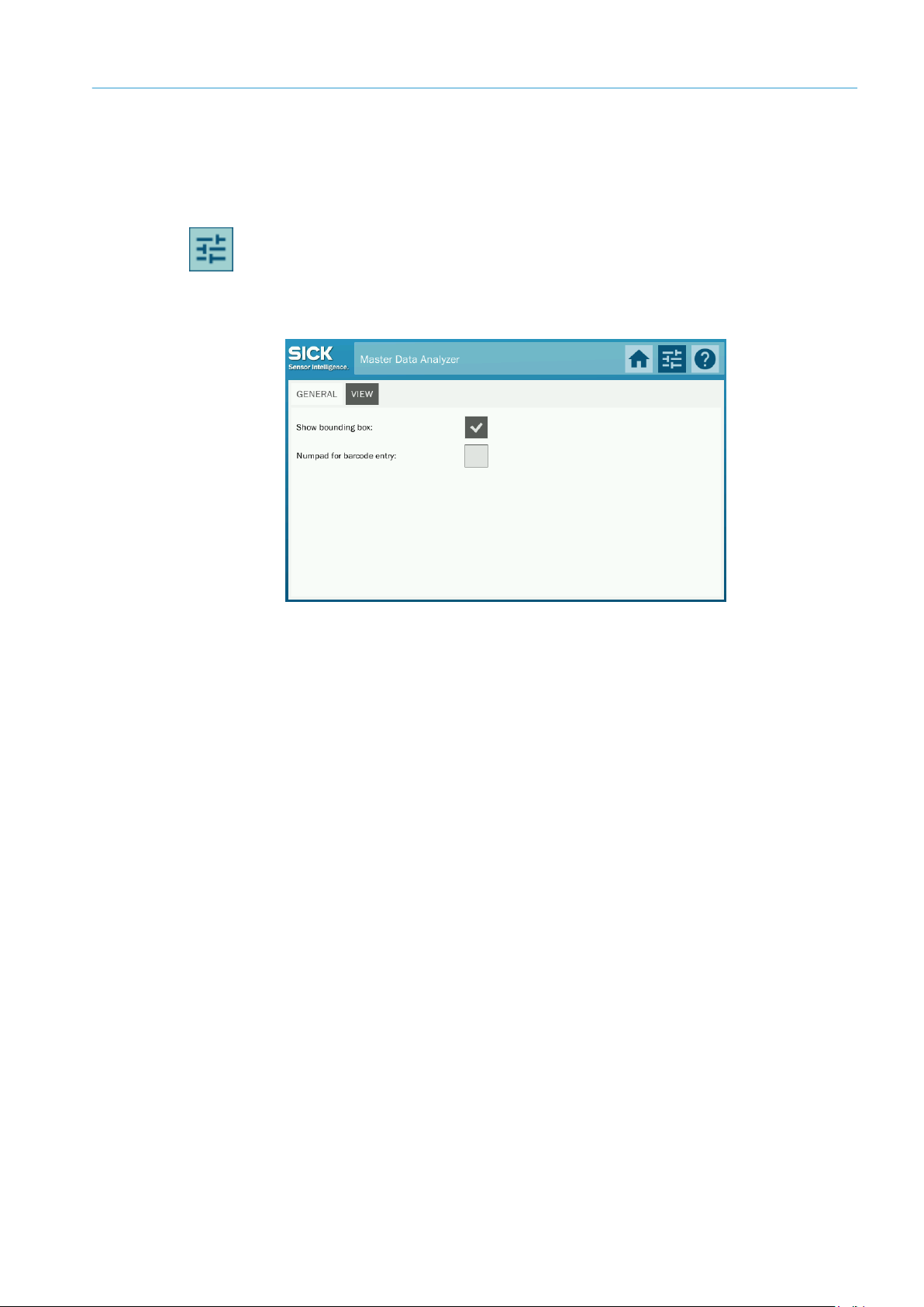
95
8020065-ZLP4/2017-08-10|SICK
Subject to change without notice
OPERATING INSTRUCTIONS | Master Data Analyzer
7.9.3 Display settings
The VIEW tab requires you to log into the Maintenance user level.
Registration
1. Click the Configuration icon on the toolbar.
2. Log into the Maintenance user level by entering the relevant password servicelevel.
The configuration area opens with the two GENERAL and VIEW tabs.
3. Switch to the VIEW tab.
OPERATION 7
Adjusting settings
The top view visualizes the smallest enveloping cuboid (the box volume) as standard. If
▸
you do not want to use this display, you will have to deactivate the Show bounding box
checkbox.
Tick the Use numberpad for barcode entry checkbox to restrict the keyboard for
▸
manually entering the bar code to the numeric keyboard (see chapter 7.3.1.1 Scanning
the bar code).
Page 96

8 MAINTENANCE AND REPAIRS
8020065-ZSP4/2017-08-10|SICK
OPERATING INSTRUCTIONS | Master Data Analyzer
Subject to change without notice
96
Device
Maintenance task
Interval*
Performed by
personnel
Optical monitoring of the glass panel for foreign
Cleaning the glass panel
4X/year
contaminated)
Trained
personnel
4X/year
contaminated)
Visual inspection of the electrical cabling and wiring for
damage
Trained
personnel
* The intervals depend on the ambient conditions and degree of contamination. In addition, the intervals must be defined
according to how significant they are for the customer process.
8 Maintenance and repairs
The following maintenance work must be carried out at the specified time intervals:
Light grid
Glass panel
Display
Housing
IP camera
Cabling
Tab. 18: Maintenance intervals
Cleaning the light grids 1x/month
bodies/damage
Visual inspection for contamination
Removal of residue from labels
Cleaning the display
Cleaning housing internal space As needed
Cleaning the duct shield housing
Daily
(or earlier if it
becomes
(or earlier if it
becomes
1x/year
Trained
Trained
personnel
Trained
personnel
Trained
personnel
Page 97

97
8020065-ZLP4/2017-08-10|SICK
Subject to change without notice
OPERATING INSTRUCTIONS | Master Data Analyzer
8.1 Maintenance and repairs
NOTE
HAZARD
HAZARD
Repair work on the individual components may only be performed by qualified and
authorized service personnel from SICK AG.
Disconnect the power to the system
Make sure the voltage supply for the Master Data Analyzer is disconnected while you
▸
are carrying out maintenance and repairs.
Remove the plug from the power outlet to disconnect the voltage supply.
▸
Risk of injury due to electrical current
The Master Data Analyzer is connected to the power supply (AC 100 to 264 V/50 to 60 Hz).
Only a qualified electrician or trained person working under the guidance and supervision
of a qualified electrician is permitted to work on electrical systems or equipment, and they
must comply with the electrical regulations.
Improper handling of live devices may lead to severe personal injury or death by electric
shock.
MAINTENANCE AND REPAIRS 8
Measures
Electrical installation and maintenance work must only be performed by electrically
▸
qualified personnel.
Standard safety requirements must be met when carrying out any work on electrical
▸
systems or equipment.
Do not touch any live parts.
▸
In the event of danger, immediately disconnect the device from the grid.
▸
Electrical connections may only be made or disconnected when there is no power in the
▸
system.
Only switch on the supply voltage when the connection tasks have been completed and
▸
the wiring has been thoroughly checked.
Only carry out maintenance and repair work when the power is off.
▸
When using extension cables with open ends, ensure that bare wire ends do not come
▸
into contact with each other (risk of short-circuit when supply voltage is switched on!).
Wires must be appropriately insulated from each other.
Page 98

8 MAINTENANCE AND REPAIRS
8020065-ZSP4/2017-08-10|SICK
OPERATING INSTRUCTIONS | Master Data Analyzer
Subject to change without notice
98
HAZARD
WARNING
WARNING
NOTE
8.1.1 Visual inspection for mechanical and electrical damage
Inspect the measurement system for mechanical and electrical damage.
Visual inspection of the cables
Check that all cable connections are securely attached.
▸
Hazards caused by damaged cable insulation
There is a risk of electrocution if the insulation on the connecting cables for the voltage
supply is damaged.
Measures
Report any damaged cables to the maintenance team without delay.
▸
Hazards due to loose connections or scorched cables
Defects such as loose connections or scorched cables must be rectified immediately.
Measures
Report any loose or damaged cables to the maintenance team without delay.
▸
Inspecting the linear guides
As opposed to a sliding guide, linear guides are hardly subject to any notable wear and
tear.
Nevertheless, it should still be ensured at regular intervals that the measurement
▸
gantry travels smoothly along the linear guides and with an equal level of resistance.
Ensure that the movement is not hindered by contamination or objects.
▸
Risk of damage due to manual lubrication
The linear guides are self-lubricating.
Measures
Do not oil or lubricate the linear guides.
▸
Risk of damage if measurement gantry is in slanted position
If the measurement gantry does not run smoothly even after removing any possible
objects disrupting its path this may denote that the measurement gantry is in a slightly
slanted position.
Measures
Please contact the manufacturer directly in this case.
▸
Page 99

99
8020065-ZLP4/2017-08-10|SICK
Subject to change without notice
OPERATING INSTRUCTIONS | Master Data Analyzer
8.1.2 Cleaning the light grids
CAUTION
NOTE
The MLG-2 modular light grids are maintenance-free. Depending on the ambient
conditions, regular cleaning is required.
Fig. 49: Cleaning – Light grids
To achieve the full optical output of the light grids, the front screens should be regularly
checked for contamination. This is especially true in harsh operating environments (dust,
abrasion, humidity, fingerprints).
Static charges can cause dust particles to adhere to the front screen.
Contamination message
3 Hz yellow
Recommendation
The MLG-2 light grid has a contamination warning which is indicated via a flashing yellow
light emitting diode on the receiver.
The yellow LED also displays the same flashing behavior during the teach-in process.
The contamination warning is shown on the display (see also chapter 9.2.1 Status
indicator on the display).
How to clean the front screen
Use a clean, soft brush to remove dust from the front screen.
▸
Then wipe the front screen with a clean, damp cloth.
▸
For cleaning, use SICK anti-static plastic cleaner (part number 5600006) and SICK lens
▸
cloth (part number 4003353).
MAINTENANCE AND REPAIRS 8
Damage to the front screen
The front screen is made of plastic. The optical output is weakened by scratches and
streaks on the front screen.
Measures
Do not use aggressive cleaning agents.
▸
Do not use abrasive cleaning agents.
▸
Avoid scratching and chafing motion on the front screen.
▸
Do not move the light grids from their position
Ensure that the light grids are not moved from their position whilst cleaning them.
▸
Page 100
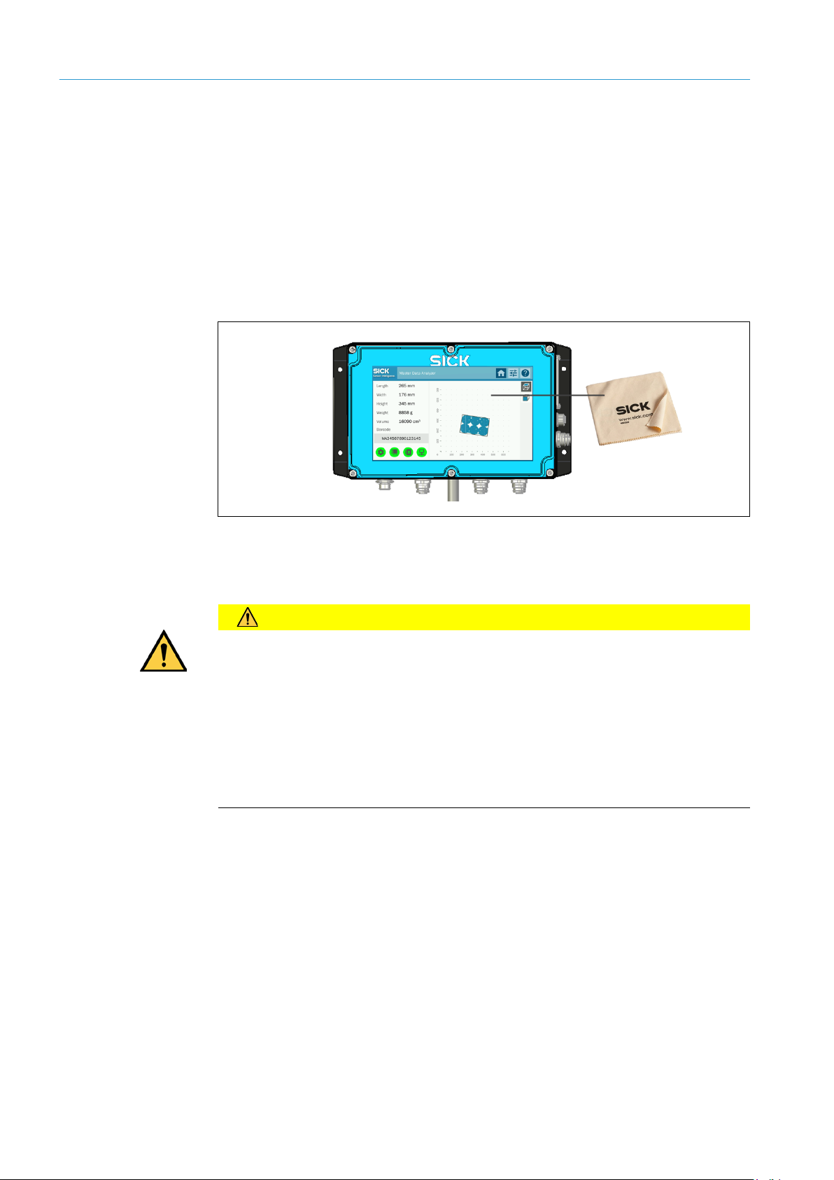
8 MAINTENANCE AND REPAIRS
8020065-ZSP4/2017-08-10|SICK
OPERATING INSTRUCTIONS | Master Data Analyzer
Subject to change without notice
100
CAUTION
8.1.3 Cleaning the display
To guarantee a long service life and full functionality, all greasy fingerprints and smear
marks should be cleaned from the touch screen.
1. The Master Data Analyzer should be switched off before any cleaning is commenced.
Note
Recommendation
If the display is on whilst cleaning, this may unintentionally trigger functions and
malfunctions.
2. Carefully wipe the areas that require cleaning with a clean, dry microfiber cloth. Use
small circular movements when doing so.
Fig. 50: Cleaning – Touchscreen display
Use the SICK lens cloth (part no. 4003353).
Damage caused by incorrect cleaning
The touchscreen is made of plastic. Scratches and streaks on the screen will impair the
device’s functionality.
Measures
Only use a soft, dry, lint-free cloth to clean the screen.
▸
Do not use any solvents during cleaning. These may damage the touchscreen.
▸
Do not exert too much pressure on the screen when cleaning.
▸
 Loading...